finite element simulation of buckling of extended beam … et al...extended shear tab connections...
TRANSCRIPT

Proceedings of the
Annual Stability Conference
Structural Stability Research Council
Orlando, Florida, April 12-15, 2016
Finite element simulation of buckling of extended beam-to-girder shear tab
connections under gravity induced shear force
Mohammad Motallebi1, Dimitrios G. Lignos2, Colin A. Rogers3
Abstract
Extended shear tab connections (either in full-depth or partial-depth configurations) have been
widely used to connect simply supported beams to the web of supporting girders. Full-scale
laboratory tests of extended beam-to-girder shear tab connections demonstrated the differences
between their observed strength and expected design strength calculated according to the AISC
design procedure. This difference is attributed to the fact that the AISC design procedure neglects
the girder web mechanism and its interaction with shear plate buckling of the tab, which are the
main governing failure modes for partial and full depth configuration of extended beam-to-girder
shear tabs, respectively. This paper aims to address the effect of flexibility of the girder web on
the buckling strength of beam-to-girder shear tab connections. The findings from a finite element
(FE) simulation of two beam-to-girder shear tab connections, tested at McGill University, are
discussed. Finite element models were developed and calibrated based on the available data from
these tests. Furthermore, symmetric boundary conditions were then implemented along the girder
axis to represent the situation where the girder supports a beam on each side. This connection
configuration will restrict the out-of-plane deformation of the girder web. Results from the FE
models demonstrate the effect of the girder web deformation and shear tab configuration on the
buckling failure mode and the ultimate strength of extended beam-to-girder connections.
1. Introduction
Extended shear tab connections consist of a steel plate, which is shop welded to the supporting
girder or column and bolted to the supported beam in the field. The increased length of the
extended shear tab allows the beam to be connected to the web of a column or the girder web (Fig.
1) without coping the beam flanges, which can be an expensive and time-consuming procedure.
Due to ease of fabrication and erection of extended shear tab connections, it has been widely used
to connect beams to girders. The shear plate can be welded solely to the web of the girder (Fig.
1a), or be connected to either the top flange (Fig. 1b) or both top and bottom flanges (Fig. 1c). The
AISC Manual of Steel Construction (2011) considers the combined flexural and shear yielding of
the shear plate, bolt bearing, flexural buckling of the shear plate, shear rupture of the shear plate,
1 Graduate Research Assistant, McGill University, < [email protected] > 2 Associate Professor, Swiss Federal Institute of Technology (EPFL), < [email protected] > 3 Associate Professor, McGill University, < [email protected] >

2
block shear rupture of the shear plate, weld tearing, and bolt shear as failure modes of extended
shear tab connection. To obtain a ductile response of the shear tab connection, the plate thickness
and the weld throat are proportioned to develop yielding of shear plate prior to bolt shear and weld
tearing, respectively. Regarding the flexural buckling of the shear plate, the AISC design method
implements equations corresponding to the flexural buckling resistance of a doubly coped beam
(Cheng et al. 1984).
a)
b)
c)
Figure 1- Extended beam-to-girder shear tab connections: a) Partial depth-unstiffened, b) Partial depth-stiffened, c)
Full depth-stiffened
It should be noted that the AISC design method (2011) was originally developed for extended
beam-to-column shear tabs; thus, a lack of guidance exists specifically for the design of beam-to-
girder shear tabs. The AISC Manual of Steel Construction (2011) considers the beam end’s shear
force (R) and its eccentric moment (Re) as the design shear force and flexural moment for the bolt
group. Furthermore, the vertical weld line which connects the shear plate to the girder web is
designed to resist shear force alone (R). The horizontal weld lines, that connect the shear plate to
the girder flanges, are not considered as load carrying welds; as such, they are detailed to have the
minimum size of weld. For a girder, which supports a beam on each side, each connection is
designed for its corresponding shear force (Rr & Rl) and a portion of the net flexural moment (Rrer-
Rlel) determined based on the designer’s engineer judgement (AISC 2011).
On the other hand, a limited number of research studies have been conducted on extended beam-
to-girder shear tabs. Sherman and Ghorbanpoor (2002) determined experimentally that yielding
and twisting of the shear plate were the governing failure modes for partial depth shear tabs in
beam-to-girder connections. In addition, plate buckling was observed as the failure mode of full
depth beam-to-girder shear tab connections. Furthermore, Goodrich (2005) tested full depth beam-
to-girder shear tabs and observed plate buckling as the governing failure mode.
Given the lack of knowledge regarding the behaviour of extended shear tabs, a research program
was carried out at McGill University to evaluate and improve the current design practice for such
connections. To study the behaviour of extended shear tabs, full-scale laboratory tests were
conducted. These tests provided a baseline to understand the complex and nonlinear behaviour of
these connections. The testing program was complemented with additional finite element
simulations. These numerical analyses, calibrated on the basis of the full-scale connection tests,
allow for a better comprehension of their behaviour and the influence of various parameters for a
wider range of loading and connection configurations. This paper presents the findings from the
finite element models of extended beam-to-girder shear tabs with full depth shear plates. The
methodology to develop these models is also presented.

3
2. Full-Scale Laboratory Testing
Several full-scale laboratory tests were conducted at McGill University (Marosi 2011, Hertz 2014,
Goldstein Apt 2015, Hertz et al. 2015) to understand the behaviour of extended shear tab
connections. The connection configurations were designed in collaboration with practicing
structural engineers to be representative of the current design practice in North America. Among
these tests, two specimens of full depth extended beam-to-girder shear tabs (Fig. 2b) were selected
to create finite element models; BG1 (Hertz 2014) & BG2 (Goldstein Apt 2015). These specimens
were nominally identical except for the thickness of shear plate, which was increased in the BG2
specimen to satisfy the AISC’s criterion for compactness of the stiffener. The girder and beam
were ASTM A992 Grade 50 (Fy=345 MPa) steel. ASTM A572 Grade 50 shear plates were snug
tightened to the beam using ASTM A325 bolts. To weld the shear tab to the supporting girder, an
E71T (Fu=490 MPa) electrode was used through the flux-cored arc welding process with additional
shielding gas (CO2).
a)
b)
Figure 2- Laboratory tests of beam-to-girder shear tabs: a) Test setup for, b) Detail of specimens
The test setup (Fig. 2a) consisted of a 12MN and a 445KN hydraulic actuator, a lateral bracing
system for the steel beam, and supporting elements for the girder. The 12MN actuator located near
the shear tab connection developed the main shear force in the connection. A half round steel
cylinder, a roller and two steel plates were placed between the top flange of beam and the head of
the actuator to allow for movement of the beam. The 445KN actuator, placed near the far end of
the beam, was used to control the vertical displacement of the beam tip as well as the rotation of
the connection. The lateral bracing system was installed to restrict lateral displacement of the
beam, without affecting its vertical displacement.
On the basis of the AISC design procedure (2011), the connection strengths corresponding to the
probable failure modes were determined (Table 1). The measured material properties of the steel
and the nominal properties of the bolts and welds were used to conduct the calculations.
4
Table 1-Predicted strength of shear tab test specimens
Predicted Strength (kN)
Failure mode BG1 BG2
Buckling of shear plate --- ---
Flexural and shear yielding of shear plate 245 326
Rupture at net section of shear plate 482 643
Bolt shear 270 270
Weld tearing 991 1072
3. Finite Element Simulation of Extended Beam-to-Girder Shear Tab Connections
Finite element simulation was adopted to obtain a deeper understanding of the behaviour of
extended beam-to-girder shear tab connections. To develop reliable FE models of the tested
specimens, all features of the FE models including geometry, boundary conditions, material
properties, element size and element type, contacts and interactions, and the loading protocol were
chosen to be representative of the real situation of the laboratory tests The details of the finite
element model are shown in Fig. 3.
Figure 3-Details of finite elements model
3.1 Geometries
The 3D finite element models of the extended beam-to-girder shear tab connections include the
beam, column, shear tab, bolts, welds and load cubes. Because the main focus of the FE analysis
was to investigate the behaviour of the shear tab connections, the stub columns and lateral braces
of the beam were replaced by appropriate boundary conditions. The accuracy of the FE models
was not affected by this replacement as measured deformations of the stub columns and lateral
braces of beams were negligible during testing. It is noteworthy to state that the bolts are placed at
the center of the bolt holes which are 2mm larger than the bolt shanks.

5
3.2 Boundary Conditions and Loading Protocol
As mentioned in Section 3.1, the stub columns were replaced by fixed boundary conditions to
create a computationally efficient FE model. To simulate the lateral braces of the beams, the lateral
displacement of the beam flanges at the locations of the braces was restricted. The loading protocol
was simulated by applying the displacements of the two actuators, recorded during the tests, to
load cubes as boundary conditions.
3.3 Material Properties
The constitutive material model in the ABAQUS software must be defined based on the true stress
– strain relationship. These values were obtained from engineering stress-strain curves of the
material by the implementation of appropriate equations. The engineering strain-stress curves of
the shear plates, beams and girders were obtained from tensile tests of coupons, extracted from the
test specimens. Regarding the bolt and weld material, the material properties were defined based
on their typical stress-strain curves, but their ultimate and yield strength were scaled to meet the
minimum specified values.
3.4 Mesh of FE Models
The FE models of shear tabs were meshed by 3D solid elements. First-order, full-integrated cubic
elements (C3D8) were used for all parts of the model, except the K-areas of the beam and girder
where the mesh consisted of first-order, full-integrated triangular prism (C3D6) elements. To
develop a computationally accurate and efficient FE model, mesh refinement analysis was
conducted to determine the appropriate size of elements. The shear plate and connecting welds
were modeled using typical element size of 3mm with three elements through the thickness of
plate. The typical element size of 10mm was used to mesh most regions of the girder except the
region in the vicinity of the shear plate, represented using typical element size of 3mm. The part
of the beam adjacent to the shear plate was meshed using typical element size of 20mm while a
lower resolution mesh (e.g. the typical element size of 40mm) was chosen for parts of the beam
away from the shear plate. The bolts were represented using elements with typical size of 1.5mm.
3.5 Contact and Interactions
Contact simulation was defined in the FE model to allow transmission of force between all
components in contact. These interactions include the surface-to-surface contact pairs between the
bolts’ shank and shear plate, bolts’ shank and beam web, shear plate and bolts’ nut, beam web and
bolts’ head, beam web and shear plate, and load cubes and beam flanges. In addition, the contact
pair between the bottom flange of the beam and the shear plate is defined to detect binding, which
could possibly happen due to large rotation of the connection. The normal behaviour of contact,
allowing separation after closure, was defined using hard contact formulation with a penalty
constraint enforcement method. Regarding the stiffness of the contact, the default value of
ABAQUS software was scaled by 0.003 (Daneshvar 2013). This value was kept constant
throughout the analysis. Regarding the tangential behaviour, the friction was defined using a
penalty formulation with a friction coefficient of 0.3 for all contact pairs, except those between the
load cubes and the flanges of beam where frictionless interaction was defined.
3.6 Geometric Nonlinearity
Geometric nonlinearities were included in the numerical models based on the large displacement
formulation. Furthermore, to trigger possible local instabilities of the shear tab connection, local

6
imperfections were introduced in the shear plate and girder in which local buckling may occur. In
order to define the local imperfections, the nodal coordinates of the shear plate and girder were
modified by scaling appropriate buckling mode shapes, obtained from eigenvalue buckling
analysis. The local imperfections for the shear plate and the girder web as well as the flanges of
the girder were proportioned to the limits of manufacturing tolerances for the web and flange of
W section (CISC 2010), respectively.
3.7 Comparison of computational and experimental results
In order to evaluate the accuracy of the numerical models, their predictions were compared with
the measured connection behaviour from laboratory tests. Among others, the developed shear force
of the connection and the out-of-plane deformation of the girder web were chosen as the critical
criteria for verification. The predictions of the numerical models are presented along with the
experimental measurements in Fig. 4.
The comparison between the deformation of the girder web of the numerical models and the two
tests demonstrate that the FE models predict reasonably well the out-of-plane deformations of the
girder web. Regarding the shear force, the calculation of the numerical model deviated from the
test measurements in the initial increments of loading. This discrepancy arises from the different
contact situation between the bolt shanks and the bolt holes in the model and in the laboratory. The
shear tab connections were snug-tightened in which bearing between the bolt shanks and bolt holes
transfers the shear force between the beam and the shear plate. Therefore, the initial response of a
snug-tightened connection depends greatly on the contact between bolts shank and bolt holes.
Since the contact situation in the tests could not be accurately measured, as mentioned in Section
3.1, the bolts were placed at the center of bolt holes, resulting in a 1mm gap around the entire
perimeter. To prevent rigid body motion of the beam, and consequently to overcome convergence
difficulties with the numerical model, a small amount of pretension (i.e. 50 MPa) was applied to
bolts. It has been shown that this level of pretension does not affect the global behaviour of
numerical connection models (Daneshvar 2013).
4. Parametric Study for Single-Sided Extended Beam-to-Girder Shear Tabs
As mentioned in section 2, the AISC manual (AISC 2011) provides design equations for each
failure mode that may possibly occur in a shear tab connection. On the other hand, it is impossible
to evaluate the accuracy of the design equation for each failure mode by conducting laboratory
tests on shear tabs due to the interaction of different failure modes. Therefore, it is necessary to
study each failure mode separately to evaluate the accuracy of current design equations and to
comprehend effects of each failure mode on the response of the tested shear tab connections. To
study the behaviour of the extended beam-to-girder shear tabs, a parametric study was conducted
in which the strength of the connection’s components including beam, shear plate, bolts, and girder
were determined. The elastic material properties were initially included in model FE-E to
determine the elastic stiffness of the shear tab connection. The inelastic material properties for
each component were then included in the FE models. The results of these FE models demonstrated
the onset of yielding and the strength of each component as compared with the results of the elastic
model FE-E. Features and findings of each model were presented in Table 2.
4.1 Results for Specimen BG1
The results of the parametric study for Specimen BG1 are illustrated in Fig. 5. The shear force is
presented versus the connection rotation and the beam rotation in Figs. 5a & 5b, respectively.

7
Displacements of LVDT 2 and LVDT 6 (Fig. 3e,f) are presented versus the connection rotation in
Figs. 5c & 5d, respectively.
a b
c d
e f Figure 4-Response of numerical model: a) shear force vs. connection rotation of Specimen BG1, b) shear force vs.
connection rotation of Specimen BG2, c) shear force versus beam rotation of Specimen BG1, d) Shear force versus
beam rotation of Specimen BG2, e) out-of-plane deformation of girder web vs connection rotation of Specimen
BG1, f) out-of-plane deformation of girder web vs connection rotation of Specimen BG2
0 0.01 0.02 0.03 0.04 0.050
100
200
300
400
500
600
Connection Rotation [rad]
Con
nec
tion
Sh
ear
Forc
e [k
N]
EXP
FE
0 0.01 0.02 0.03 0.04 0.050
100
200
300
400
500
600
Connection Rotation [rad]
Con
nec
tion
Sh
ear
Forc
e [k
N]
EXP
FE
0 0.02 0.04 0.06 0.080
100
200
300
400
500
600
Beam Rotation [rad]
Co
nn
ecti
on
Sh
ear
Fo
rce
[kN
]
EXP
FE
0 0.02 0.04 0.06 0.08 0.1 0.12 0.140
100
200
300
400
500
600
Beam Rotation [rad]
Co
nn
ecti
on
Sh
ear
Fo
rce
[kN
]
EXP
FE
8
The response of the FE model with elastic properties (i.e. F.E-E) can be considered as a bilinear
curve by ignoring its initial portion. Its stiffness decreased significantly at 670 KN shear force
corresponding to 3.75% of connection rotation. Since only elastic material properties were
considered in this model, the change in slope of the curve arose from the geometric nonlinearity
that occurred during loading, which resulted from the out-of-plane deformations of either the
girder web or the shear plate. As shown in Fig. 5c the slope of the out-of-plane deformation of the
shear plate (LVDT2) increased at a shear force equal to 570 KN and 670 KN corresponding to
3.25% and 3.75% connection rotation. The last slope change resulted in a stiffness degradation of
the shear tab connection; it therefore can be identified as the bifurcation point of elastic buckling.
Figure 4d shows a significant increase in the slope of the out-of-plane deformation of the girder
web (LVDT6) at a connection rotation equal to 3.75%, which corresponds to a 670 KN shear force.
Prior to the buckling of the shear plate, its stiffened section, which is confined between the flanges
and the web of the girder, performed as a beam with flexible supports. As such, the transverse
force, mobilized due to the existing eccentricity of the shear force, was distributed between the
girder flanges and web based on their in-plane and out-of-plane stiffness, respectively. A large
component of the transverse force transferred to the girder flanges due to their higher in-plane
stiffness as compared to the out-of-plane stiffness of the girder web. Once the shear plate had
buckled, its flexural stiffness degraded, therefore the major portion of the transverse force
transferred to the girder web. Therefore, the stiffness of the connection decreased when the shear
plate buckled and this change in force transfer occurred. The out-of-plane deformation of shear
plate is presented in Fig. 6.
Table 2-Features and capabilities of F.E models
Model Features Findings
F.E-E All components were elastic. Elastic stiffness and elastic buckling
strength were determined.
F.E-E-G All components were elastic except the
girder.
Out-of-plane bending capacity of
girder web was determined.
F.E-E-SH All components were elastic except the
shear plate. Strength of shear plate was determined
F.E-E-Pl Elastic and inelastic material properties
were assigned to all components.
In addition to strength of connection,
the interactions between failure modes
were determined.
F.E-E-Pl-Imp
Elastic and inelastic material properties
were assigned to all components. In
addition, initial imperfections were assigned
to trigger possible buckling of shear tab.
Effects of initial imperfection on the
behaviour of shear tabs were
determined.
Comparison between the elastic model (F.E-E) and the model with yieldable girder (F.E-G),
demonstrated the effect of yielding of the girder. Prior to the buckling of the shear plates (675 KN
shear force, 3.75% rotation), their response was approximately identical as a large amount of
transverse force was carried by the in-plane action of the girder flanges. After the buckling of the
shear plate, the transverse force could not transfer to the girder flanges, hence the web of the girder
resisted the transverse force through out-of-plane bending. At this point the onset of the yielding
of the girder web was observed in the model F.E-G. As the yielding propagated in the girder web,
the stiffness of the connection continued to decrease up to 715 KN shear force (4.3% rotation), at
which point the connection reached its capping strength. This plateau of strength of the FE model
with a yieldable girder was the result of yielding of a large part of the girder web and the formation

9
of the girder mechanism. The comparison between models F.E-E and F.E-G demonstrated the
effect of girder web yielding and the resulting increase of the out-of-plane deformation of shear
plate. Furthermore, regarding the out-of-plane deformation of the girder web, the elastic model
and the model with a yieldable girder show identical predictions up to the onset of the girder web
yielding, which is largely influenced by the buckling of the shear plate. The propagation of yielding
in the girder web of model E.F-G is depicted in Fig. 7.
a b
c d Figure 5-Predictions of numerical models: a) shear force versus connection rotation, b) shear force versus beam
rotation, c) out-of-plane deformation of shear plate versus connection rotation, d) out-of-plane deformation of girder
web versus connection rotation.
For the numerical model that incorporated a yieldable shear plate, the onset of yielding was
observed at 110KN (1.15%) on the neck of the shear tab where its depth increased to extend to the
bottom flange of the girder. The out-of-plane deformation of the shear plate was negligible at this
point. As the yielding propagated to the stiffened part of the shear plate, the out-of-plane
deformations of the shear plate and the girder web increased. The stiffness of the connection
decreased at a shear force of 235 KN (1.5% rotation) when the slope of the curve illustrating the
out-of-plane deformation of the girder web (LVDT6) increased significantly. This decrease of
connection stiffness was attributed to the local yielding of the shear plate and consequently its
inability to transfer transverse force to the girder flanges. It should be noted that the slope of the
out-of-plane deformation of the shear plate (LVDT2) increased significantly at 2.35% rotation
(285KN shear force).
0 0.01 0.02 0.03 0.04 0.050
100
200
300
400
500
600
700
800
900
Connection Rotation [Rad]
Con
nec
tion
Sh
ear
Forc
e [k
N]
F.E-E
F.E-E-G
F.E-E-Bo
F.E-E-Be
F.E-E-SH
F.E-Pl
F.E-Pl-Imp
0 0.02 0.04 0.06 0.080
100
200
300
400
500
600
700
800
900
Beam Rotation [Rad]C
on
nec
tion
Sh
ear
Forc
e [k
N]
F.E-E
F.E-E-G
F.E-E-Bo
F.E-E-Be
F.E-E-SH
F.E-Pl
F.E-Pl-Imp
0 0.01 0.02 0.03 0.04 0.050
5
10
15
20
Connection Rotation [Rad]
LV
DT
2 D
isp
lace
men
t [m
m]
F.E-E
F.E-E-G
F.E-E-Bo
F.E-E-Be
F.E-E-SH
F.E-Pl
F.E-Pl-Imp
0 0.01 0.02 0.03 0.04 0.050
5
10
15
20
Connection Rotation [Rad]
LV
DT
6 D
isp
lace
men
t [m
m]
F.E-E
F.E-E-G
F.E-E-Bo
F.E-E-Be
F.E-E-SH
F.E-Pl
F.E-Pl-Imp

10
a b Figure 6-Out-of-plane deformation of shear plate of model F.E-E at: a) θ=3.75%, b) end of analysis
a b c Figure 7-Yielding of web of girder in the model E.F-E-G at: a) θ=3.75%, b) θ=4.30%, c) end of analysis. (The gray
colour represents yielded regions)
Regarding the model with a yieldable beam (F.E-E-Be); yielding in the beam web began due to
bearing around the vertical bolt holes, farthest from the girder, at 265kN shear force (1.75%
rotation). Yielding then propagated over the beam web all along this vertical row of bolts at 420KN
(3% rotation). Almost all sections of the beam web between the bolt holes and at the location of
load application yielded at 475KN (3.8% rotation). At this point the stiffness of the connection
decreases significantly and yielding propagated to other regions of beam web and beam flanges.
The propagation of yielding of the beam is shown in Fig. 9.
As shown in Fig. 5, the predictions of the numerical model comprised of components that could
experience yielding (F.E-Pl) were similar to the model with a yieldable shear plate (F.E-E-SH).
The onset of yielding occurred at the neck of the shear plate at shear force of 110KN (rotation of
1.15%). A decrease of stiffness of the connection occurred at 235KN (1.5% rotation) when the
slope of the curve presenting the out-of-plane deformation of the girder web (LVDT6) increased
significantly. The yielding of the girder web began at 250KN (1.75% rotation). Finally, the slope
of the out-of-plane deformation of the shear plate (LVDT2) increased significantly at 2.35%
11
rotation (285KN shear force). The yielding of the girder web of model F.E-Pl is presented in Fig.
10.
a b c d
e f g h Figure 8-Prediction of model FE-E-SH for: a) stress of shear plate at θ=1.15%, b) out-of-plane deformation of girder
web at θ=1.15%, c) stress of shear plate at θ=1.5%, d) out-of-plane deformation of girder web at θ=1.50, e) stress of
shear plate at θ=2.35%, f) out-of-plane deformation of girder web at θ=2.35%; g) stress of shear plate at end of
analysis, h) out-of-plane deformation of girder web at end of analysis (The gray colour represents yielded regions)
To trigger possible buckling of the shear plate, imperfections were added to the model F.E-Pl to
create model F.E-Pl-Imp. Yielding began at the neck of the shear plate at a shear of 100KN
(rotation of 1.1%). Due to the imperfections, the slope of the representative curves for out-of-plane
girder web and shear plate deformation increased significantly at 180KN shear force (1.35%
rotation). The stiffness of the connection decreased at 225KN (1.5% rotation). The web of the
girder began to yield at 240KN (1.7% rotation). The slope of the LVDT2 deformation increases
significantly at 2.45% rotation (260KN).
4.2 Results of Specimen BG2
The results of the parametric study for Specimen BG2 are presented in Fig. 11. From this figure,
the out-of-plane deformation of the shear plate of model FE-E began to increase significantly at
975KN (Fig. 11c, 4.65% rotation). The out-of-plane deformation of the girder web started to
increase at 1275KN (5.60% rotation), while the stiffness of the connection decreased. The
prediction of the model with a yieldable girder F.E-E-G deviated from the predictions of the elastic
12
model F.E-E when the shear force reached higher than 975KN (4.65% rotation) due to yielding of
the girder web. The web of the girder began to yield at a shear force of 715KN (3.70% rotation).
The F.E-E-G model reached its maximum strength at 1300 KN (5.60 %rotation). For model F.E-
E-SH, the onset of yielding was observed at 160KN (1.65%) at the neck of the shear tab. The slope
of the curve corresponding to the out-of-plane deformation of the girder web increased
significantly at a shear force of 290KN (2.1% rotation), and the stiffness of the connection began
to decrease slightly. The stiffness of the connection decreased significantly at 475KN shear force
(2.9% rotation), while the slope of the curve presenting the out-of-plane deformation of shear plate
(LVDT2) increased significantly. As shown in Fig. 11, the prediction of model F.E-Pl slightly
deviated from the prediction of model F.E-E-SH when the shear force reached higher than 290KN
(2.25% rotation) due to yielding of the girder web. Yielding was observed to occur at the neck of
the shear plate at a shear of 160KN (rotation of 1.65%). The slope of the curves presenting the out-
of-plane deformation of the girder web increased significantly at a shear force of 290KN (2.25%
rotation), while the stiffness of the connection began to decrease. The web of the girder began to
yield at a shear force of 350KN (2.5% rotation). The stiffness of the connection decreased
significantly at 460 KN shear force (3.1% rotation). On the other hand, the slope of the curve for
out-of-plane deformation of the shear plate (LVDT2) increased significantly.
a b
c d Figure 9- Prediction of model FE-E-Be for yielding of beam at: a) θ=1.75%, b) θ=3%, c) θ=3.8%, d) end of analysis
(The gray colour represents yielded regions)

13
a b
c
d e
Figure 10- Prediction of model F.E-Pl for stress of girder web at: a) θ=1.15%, b) θ=1. 50%, c) θ=1.75%, d)
θ=2.35%, e) end of analysis (The gray colour represents yielded regions)
a b
c d Figure 11- Predictions of numerical models: a) shear force versus connection rotation, b) shear force versus beam
rotation, c) out-of-plane deformation of shear plate versus connection rotation, d) out-of-plane deformation of girder
web versus connection rotation.
0 0.02 0.04 0.06 0.080
500
1000
1500
2000
Connection Rotation [Rad]
Con
nec
tion
Sh
ear
Forc
e [k
N]
F.E-E
F.E-E-G
F.E-E-Bo
F.E-E-Be
F.E-E-SH
F.E-Pl
F.E-Pl-Imp
0 0.05 0.1 0.150
500
1000
1500
2000
Beam Rotation [Rad]
Con
nec
tion
Sh
ear
Forc
e [k
N]
F.E-E
F.E-E-G
F.E-E-Bo
F.E-E-Be
F.E-E-SH
F.E-Pl
F.E-Pl-Imp
0 0.02 0.04 0.06 0.080
5
10
15
20
Connection Rotation [Rad]
LV
DT
2 D
isp
lace
men
t [m
m]
F.E-E
F.E-E-G
F.E-E-Bo
F.E-E-Be
F.E-SH
F.E-Plastic
F.E-Imp
0 0.02 0.04 0.06 0.080
5
10
15
20
Connection Rotation [Rad]
LV
DT
6 D
isp
lace
men
t [m
m]
F.E-E
F.E-E-G
F.E-E-Bo
F.E-E-Be
F.E-E-SH
F.E-Pl
F.E-Pl-Imp
14
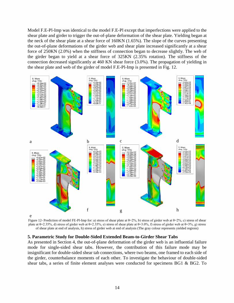
Model F.E-Pl-Imp was identical to the model F.E-Pl except that imperfections were applied to the
shear plate and girder to trigger the out-of-plane deformation of the shear plate. Yielding began at
the neck of the shear plate at a shear force of 160KN (1.65%). The slope of the curves presenting
the out-of-plane deformations of the girder web and shear plate increased significantly at a shear
force of 250KN (2.0%) when the stiffness of connection began to decrease slightly. The web of
the girder began to yield at a shear force of 325KN (2.35% rotation). The stiffness of the
connection decreased significantly at 460 KN shear force (3.0%). The propagation of yielding in
the shear plate and web of the girder of model F.E-Pl-Imp is presented in Fig. 12.
a b c d
e
f g h
Figure 12- Prediction of model FE-Pl-Imp for: a) stress of shear plate at θ=2%, b) stress of girder web at θ=2%, c) stress of shear
plate at θ=2.35%, d) stress of girder web at θ=2.35%, e) stress of shear plate at θ=3.0%, f) stress of girder web at θ=3%, g) stress
of shear plate at end of analysis, h) stress of girder web at end of analysis (The gray colour represents yielded regions)
5. Parametric Study for Double-Sided Extended Beam-to-Girder Shear Tabs
As presented in Section 4, the out-of-plane deformation of the girder web is an influential failure
mode for single-sided shear tabs. However, the contribution of this failure mode may be
insignificant for double-sided shear tab connections, where two beams, one framed to each side of
the girder, counterbalance moments of each other. To investigate the behaviour of double-sided
shear tabs, a series of finite element analyses were conducted for specimens BG1 & BG2. To
15
decrease computational costs, symmetric boundary conditions were implemented along the girder
axis and a beam and half of girder section were included in these F.E models.
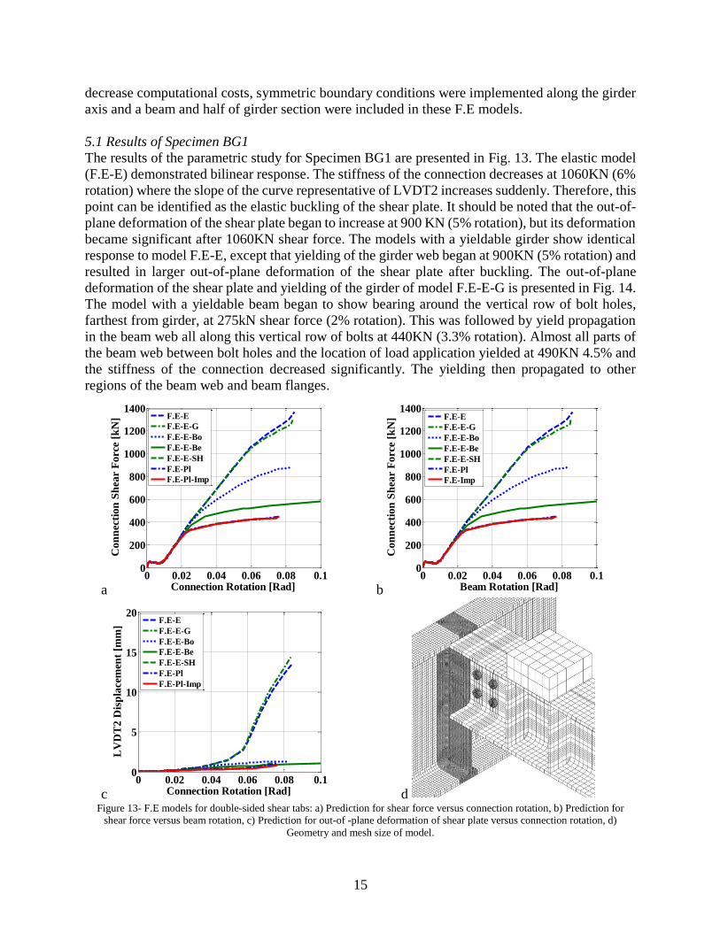
5.1 Results of Specimen BG1
The results of the parametric study for Specimen BG1 are presented in Fig. 13. The elastic model
(F.E-E) demonstrated bilinear response. The stiffness of the connection decreases at 1060KN (6%
rotation) where the slope of the curve representative of LVDT2 increases suddenly. Therefore, this
point can be identified as the elastic buckling of the shear plate. It should be noted that the out-of-
plane deformation of the shear plate began to increase at 900 KN (5% rotation), but its deformation
became significant after 1060KN shear force. The models with a yieldable girder show identical
response to model F.E-E, except that yielding of the girder web began at 900KN (5% rotation) and
resulted in larger out-of-plane deformation of the shear plate after buckling. The out-of-plane
deformation of the shear plate and yielding of the girder of model F.E-E-G is presented in Fig. 14.
The model with a yieldable beam began to show bearing around the vertical row of bolt holes,
farthest from girder, at 275kN shear force (2% rotation). This was followed by yield propagation
in the beam web all along this vertical row of bolts at 440KN (3.3% rotation). Almost all parts of
the beam web between bolt holes and the location of load application yielded at 490KN 4.5% and
the stiffness of the connection decreased significantly. The yielding then propagated to other
regions of the beam web and beam flanges.
a b
c d Figure 13- F.E models for double-sided shear tabs: a) Prediction for shear force versus connection rotation, b) Prediction for
shear force versus beam rotation, c) Prediction for out-of -plane deformation of shear plate versus connection rotation, d)
Geometry and mesh size of model.
0 0.02 0.04 0.06 0.08 0.10
200
400
600
800
1000
1200
1400
Connection Rotation [Rad]
Con
nec
tion
Sh
ear
Forc
e [k
N]
F.E-E
F.E-E-G
F.E-E-Bo
F.E-E-Be
F.E-E-SH
F.E-Pl
F.E-Pl-Imp
0 0.02 0.04 0.06 0.08 0.10
200
400
600
800
1000
1200
1400
Beam Rotation [Rad]
Con
nec
tion
Sh
ear
Forc
e [k
N]
F.E-E
F.E-E-G
F.E-E-Bo
F.E-E-Be
F.E-E-SH
F.E-Pl
F.E-Imp
0 0.02 0.04 0.06 0.08 0.10
5
10
15
20
Connection Rotation [Rad]
LV
DT
2 D
isp
lace
men
t [m
m]
F.E-E
F.E-E-G
F.E-E-Bo
F.E-E-Be
F.E-E-SH
F.E-Pl
F.E-Pl-Imp

16
For the numerical model with a yieldable shear plate, the onset of yielding occurred at the neck of
the shear plate at 210KN (1.7%), but its out-of-plane deformation was negligible. Unlike the
single-sided connections, the yielding propagated along the bolt line instead of the stiffened part
of the shear plate. The total height of shear plate along the bolt line yielded at 2.5% rotation (330
KN). The stiffness of the connection decreased significantly at this point. The slope of the curve
representative of LVDT2 deformation increased significantly at 6.2% rotation (430KN). It should
be noted that the predictions of models F.E-Pl and F.E-Pl-Imp were close to those of the model
with a yieldable shear plate. This is due to the fact that the corresponding shear force demand is
not sufficient to develop yielding in the girder web. The out-of-plane deformation and stress of the
shear plate are shown in Fig. 15.
a b c
d e f
Figure 14-Predictions of model F.E-G for: a) out-of-plane deformation at θ=5%, b) out-of-plane deformation at
θ=6%, c) out-of-plane deformation at end of analysis, d) stress on the web girder at θ=5%, e) stress on the web
girder at θ=6%, f) stress on the web girder at end of analysis (The gray colour represents yielded regions)
5.2 Results of Specimen BG2
As shown in Fig. 16, the slope of the graph representing LVDT2 deformation of model F.E-E
started to increase at 1810KN (8.2% rotation), then it increased again at 2440KN (10% rotation).
Although the shear plate experienced large out-of-plane deformation, the stiffness of the
connection remain constant. In the F.E model with a yieldable girder, the mid-depth of girder web
yielded at 1740KN shear force (7.85% rotation), and the stiffness of connection decreased slightly.

17
The connection reached its ultimate strength at 1800KN (8.25% rotation) when the entire depth of
the girder web yielded. The slope of the graph representing the out-of-plane deformation of the
shear plate started to increase at 1800KN (8.25% rotation) and significantly changed at 10%
rotation (1875KN). This out-of-plane deformation of the girder web can be attributed to the
yielding of girder web, which performed as the boundary condition of the shear plate and restricted
the rotation of the edge of the shear plate. The propagation of yielding on the girder web of model
F.E-E-G is presented in Fig. 17.
a
b
c
d
e
f
g
h
Figure 15-Prediction of model F.E-G for stress of: a) shear plate at θ=1.7%, b) girder web at θ=1.7%, c) shear plate
at θ=2.5%, d) girder web at θ=2.5%, e) shear plate at θ=6.2%, f) girder web at θ=6.2%, g) shear plate at end of
analysis, h) girder web at end of analysis (The gray colour represents yielded regions)
For the model with a yieldable shear plate, yielding initiated at the neck of shear plate at 240KN
shear force (2.1% rotation) and propagated along the vertical row of bolts, closest to the girder, at
380KN shear force (3% rotation) and resulted in a significant decrease of the connection stiffness.
The connection reached to its plateau for strength at 630KN (7.8% rotation). The results of the
model FE.Pl deviated from the results of the model F.E-E-SH in level of shear force higher than
440 KN (rotation 3.7%) in which web of beam yielded a long the net section of vertical row of
bolt, farthest from girder. Due to yielding of the beam, it experienced a large rotation; the
connection reached its plateau of strength at 608KN shear force (12.3% rotation). It should be

18
noted that the results of model F.E-Pl-Imp were identical to those of model F.E-Pl, as the yielding
of beam web governed the behaviour of the connection. To prevent the effect of beam yielding
from dominating the results of the numerical model, all components of the connection in model
F.E-Pl-Be were defined to experience yielding, except for the beam which was assigned elastic
material properties. The results of this model, F.E-Pl-Imp-Be, were identical to the model with a
yieldable shear tab because the level of shear force was not sufficient to initiate yielding of the
girder web.
a b
c Figure 16- Predictions of numerical model: a) Shear force versus connection rotation, b) Shear force versus beam
rotation, c) Out-of-plane deformation of shear plate versus connection rotation.
6. Discussion
A comparison of the results of the lab tests and numerical models for single-sided shear tabs with
results of F.E models of double-sided shear tabs demonstrated their different failure modes. Local
yielding of the shear plates in single-sided shear tabs resulted in the application of transverse force
to the girder web which was resisted by out-of-plane bending. Due to the limited out-of-plane
bending capacity of the girder web yielding occurred, which resulted in the formation of a girder
web mechanism. Furthermore, the observed strength of single-sided specimen BG2 (520KN) was
much larger than the design strength, which was based on the shear failure of the bolt group
calculated using the ICR method with the eccentricity equal to the distance between the bolt line
and the weld line (270KN). This large difference demonstrated that the effective eccentricity of
the bolt group was smaller than assumed. Comparison between results of the single-sided
0 0.02 0.04 0.06 0.08 0.1 0.12 0.140
500
1000
1500
2000
2500
3000
3500
Connection Rotation [Rad]
Con
nec
tion
Sh
ear
Forc
e [k
N]
F.E-E
F.E-E-G
F.E-E-Bo
F.E-E-Be
F.E-E-SH
F.E-Pl
F.E-Pl-Be
F.E-Pl-Imp
F.E-Pl-Be-Imp
0 0.02 0.04 0.06 0.08 0.1 0.12 0.14 0.160
500
1000
1500
2000
2500
3000
3500
Beam Rotation [Rad]
Con
nec
tion
Sh
ear
Forc
e [k
N]
F.E-E
F.E-E-G
F.E-E-Bo
F.E-E-Be
F.E-E-SH
FE-Pl
F.E-Pl-Be
F.E-Pl-Imp
FE-Pl-Be-Imp
0 0.02 0.04 0.06 0.08 0.1 0.12 0.140
5
10
15
20
Connection Rotation [Rad]
LV
DT
2 D
isp
lace
men
t [m
m]
F.E-E
F.E-E-G
F.E-E-Bo
F.E-E-Be
F.E-E-SH
F.E-Pl
F.E-Pl-Be
F.E-Pl-Imp
F.E-Pl-Be-Imp

19
connections illustrated the stable behaviour of the shear tab when the compactness ratio for
stiffeners was met. On the other hand, shear plate yielding along the net section of the vertical row
of bolts, closest to the girder, was observed as the governing failure mode for double-sided shear
tabs. The observed strength of double-sided shear tabs for specimens BG1 & BG2 (430KN and
630KN, respectively) were close to the predictions for the rupture of their shear plate at the net
section (482KN & 643KN for BG1 & BG2, respectively).
a b
c d Figure 17- Prediction of model F.E-G for stress of girder web at: a) θ=7.85%, b) θ=8.25%, c) θ=9%, d) end of
analysis
7. Conclusions
This paper presents a summary of results from finite element models that were developed to study
the behaviour of extended beam-to-girder shear tab connections with full depth shear plates. A
comparison of the numerical predictions and the experimental data from representative tests of
such connections demonstrated the ability of the numerical models to detect out-of-plane bending
of the girder web, as well as yielding of the shear plate and girder. The main findings of the finite
element study are summarized as follows:
Single-sided extended beam-to-girder shear tabs with full depth shear plates fail due to
local yielding of the shear plate, and consequently the out-of-plane bending of the girder
web. Therefore, the out-of-plane deformation of the girder web should be considered as a
potential failure mode in the design procedure of single-sided extended beam-to-girder
shear tab connections.
Single-sided extended beam-to-girder shear tabs with full depth shear plates experience
shear forces much higher than those anticipated based on design values representative of
shear failure of the bolt group. This demonstrates that the effective eccentricity of the bolt
group is significantly smaller than the assumed value, the distance between weld line and
the center of the bolt group.
The use of shear plates that satisfy the AISC compactness ratio for stiffeners results in a
more stable behaviour of single-sided shear tabs as compared to slender stiffeners. They

20
can reach higher shear force after the local yielding of the shear plate in comparison to
slender stiffeners.
The behaviour of double sided extended beam-to-girder shear tabs with full depth shear
plates is completely different than single-sided ones. These connections fail due to yielding
and rupture of the shear plate at the net section of vertical row of bolts, closest to the girder.
Acknowledgments
The authors would like to thank the ADF Group Inc. and DPHV Structural Consultants for their
generous technical and financial support, as well as the Natural Sciences and Engineering Research
Council of Canada. The finite element computations were conducted at the McGill University
supercomputer Guillimin, which is managed by Calcul Québec and Compute Canada. The
supercomputer operation is funded by the Canada Foundation for Innovation (CFI), NanoQuébec,
RMGA and the Fonds de recherche du Québec - Nature et technologies (FRQ-NT).
References
AISC (2011). "Steel Construction Manual, 14th edition". American Institute of steel Construction,
Chicago, IL.
Cheng, J.-J., Yura, J., Johnson C. (1984). "Design and behavior of coped beams", University of
Texas at Austin, Austin, TX.
CISC (2010). "Handbook of Steel Construction". Canadian Institite of Steel Construction,
Markham, ON.
Daneshvar, H. (2013). "One-sided Steel Shear Connections in Column Removal Scenario". P.h.D,
University of Alberta, Edmonton, AL.
Goldstein Apt, N. (2015). "Testing of extended shear tab and coped beam-to-girder connections
subject to shear loading". M.Sc. Thesis, McGill University, Montreal, QC.
Goodrich, W. (2005). "Behavior of extended shear tabs in stiffened beam-to-column web
connections". M.Sc. Thesis, Vanderbilt University, Nashville, TN.
Hertz, J. (2014). "Testing of extended shear tab connections subjected to shear". M.Sc. Thesis,
McGill University, Montreal, QC.
Hertz, J., Lignos, D.G., Rogers, C.A. (2015). "Full scale testing of extended beam-to-column
and beam to-girder shear tab connections subjected to shear", 8th International Conference on
Behavior of Steel Structures in Seismic Areas, Shanghai, China.
Marosi, M. (2011). "Behaviour of single and double row bolted shear tab connections and weld
retrofits". M.Sc. Thesis, McGill University, Montreal, QC.
Sherman, D. R., Ghorbanpoor, A. (2002). "Design of extended shear tabs", University of
Wisconsin-Milwaukee, Milwaukee, WI.