finite element analysis of an aluminium alloy sheet in a v ... · finite element analysis of an...
TRANSCRIPT
International Journal of Theoretical and Applied Mechanics
ISSN 0973-6085 Volume 12 Number 2 (2017) pp 331-342
copy Research India Publications
httpwwwripublicationcom
Finite Element Analysis of an Aluminium Alloy Sheet
in a V-Die Punch Mechanism Considering Spring-
Back Effect
Shirish Ghimire1a Yogesh Emeerith2b Rohit Ghosh3c Sushovan Ghosh4d
1 2 3 4 BTech Students Department of Mechanical Engineering National Institute of Technology Durgapur 713209 WB India
Dr Rabindra Nath Barman5e
5 Assistant Professor Department of Mechanical Engineering National Institute of Technology Durgapur 713209 WB India
Abstract
Sheet metal parts are used to manufacture a wide range of products Bending
and cutting the sheets into appropriate shapes by means of the physical process
of shearing is the very first step in forming such a part The current work is an
attempt to provide the readers with an appropriate understanding regarding the
deformation behavior of an aluminium alloy sheet by performing the finite
element analysis (FEM) for two distinct die angles The metal sheet is
analyzed before fatigue failure and with the help of a software based analysis
the paper explores the phenomena of spring-back associated with the metal
sheet during its deformation while subjected to the set of V-die punch
designed with suitable dimensions The V-die punch as well as the alloy sheet
is modeled in Solidworks 130 and their dimensions have been taken from
practical standards Finite element analysis for the same is carried out in
ANSYS Workbench 160
Keywords Solidworks 130 ANSYS Workbench 160 V-die punch Finite
element analysis
332 Shirish Ghimire et al
1 Introduction
Blanking and punching are one of the oldest manufacturing operations Their
applications range from components of very light to heavy appliances and
machineries [1] Punching is a metal forming process that uses a punch press to force
a tool called a punch through the work piece to create a hole via shearing When a
specially shaped punch is used to create multiple usable parts from a sheet of material
the process is known as blanking [2]During blanking the part is subjected to
complex solicitations such as deformation hardening and crack initiation and
propagation The theoretical modeling of such processes is very difficult due to the
complexity in describing the different stages of the whole shearing process starting
with the elastic stage and ending with the total separation of the sheet metal [3] Small
punch test (SPT) Ball punch Test Disk Bend test as well as Shear Punch Test [4-9]
are the techniques developing to characterize the mechanical behavior of small
specimens The concept of the small V-die punching is based on placing a thin metal
sheet specimen on the die and then the v shaped punch is applied to get the desired
shape In this process the feed is applied to the metal sheet horizontally and the
punching is done vertically In order to get the stable punching and the good punching
edge quality of the al alloy and stainless steel alloy sheets [10] it is necessary to
choose a narrow punch-die clearance and the heat sheet before punching Reducing
the clearance my increase the bright zone and also reduce the fracture zone as well as
the fracture angle but if the clearance is reduced the punching force and the tooling
wear increases [11] An experimental investigation had been carried out to study the
effect of die angle on the quality of extruded product ie surface finish and hardness
of cold extruded aluminum The die angles used were 30 45 and 60 ordms [12] Similarly
deformation in copper was observed using ECAE technique under variable die angles
The die angles used were 90 ordm and 120 ordm for this research [13] J W PILARCZYK
and J MARKOWSKI studied the effect of die angle on strain and stress state in
process of drawing of steel for pre-stressed concrete keeping 8 12 and 18 ordm dies for
the process [14] Similarly five different die angles (15 30 45 60 and 90) were used
to investigate the extrusion behavior of wrought aluminum alloys [15] Spring-back is
a geometric change that a sheet metal experiences after it gets rid of the tool forces in
a punching process Spring-back effect results in slight displacement of the sheet
metal in the direction of the return stroke of the punch Spring-back has a very
significant role in sheet metal bending process It leads to some geometric changes in
the product A research work was carried out for reflecting the different parameters on
spring-back in U-die bending of different materials with different sheet thickness and
tip radius [16]If not correctly predicted and compensated for spring-back will cause
the final part shape to deviate from design specifications and to create assembly
problems [17] H Laurent conducted the Spring-back study of aluminum alloy in
warm forming conditions A split-ring test was used to analyze the influence of
temperature during forming over Spring-back The obtained experimental results were
compared to the numerical simulations [18] A research was done earlier which
studied the spring-back effect in both V-die and U-die punching mechanism Spring-
Finite Element Analysis of an Aluminium Alloy Sheet in a V-Die Punchhellip 333
back can only be controlled and minimized but quite difficult to be eliminated [19]
However a new technique was proposed to eliminate the spring-back of high-strength
steel (HSS) sheets in the U-bending process In this technique spring-back is
eliminated using counter-punch [20] The reason die angle change is to compensate
for spring-back [21] Friction plays a major role in metal forming processes because
of its direct interaction with die and work-piece Friction creates obstacles in the free
movement and significantly affects the deformation of the work-piece The co-
efficient of friction should be specified at the die-work interface [22] It was also seen
that the punch load increases significantly with the increase in co-efficient of friction
[23] PANKAJ TOMAR also investigated the effect of friction at the die-billet
interface for a commercially pure aluminum However this study was done for
hydrostatic extrusion of aluminum [24] In this analysis we are considering that metal
sheets are homogeneous and neglecting the surface roughness
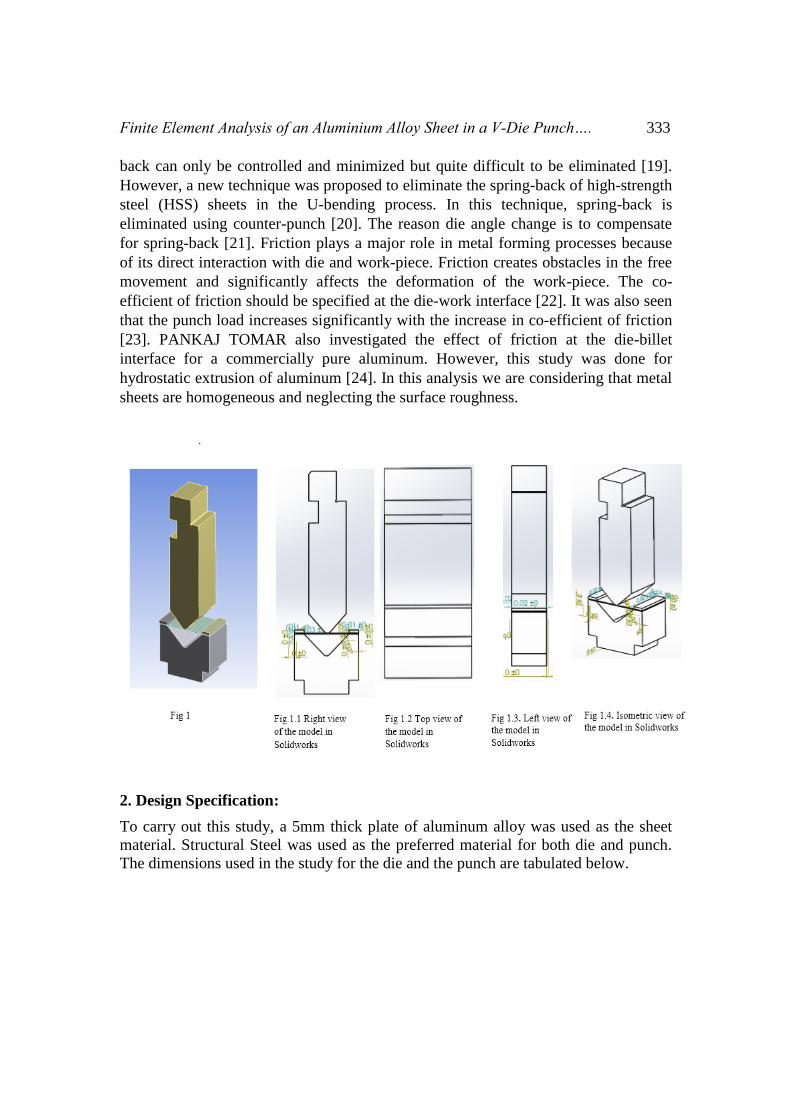
2 Design Specification
To carry out this study a 5mm thick plate of aluminum alloy was used as the sheet
material Structural Steel was used as the preferred material for both die and punch
The dimensions used in the study for the die and the punch are tabulated below
334 Shirish Ghimire et al
ITEMS VALUES
Length 2950 mm
Width 3303 mm
Depth 1970 mm
Fillet 2 mm
Die opening 23 mm
Table 21 dimensions for a 90ordm punch Table 22 dimensions for a 90ordm die
ITEMS VALUES
Length 2950 mm
Width 3303 mm
Depth 1970 mm
Fillet 2 mm
Die opening 23 mm
Table 23 dimensions for a 120ordm punch Table 24 dimensions for a 120ordm die
3 Objectives
The objective of this study is to compare the deformations in the aluminum steel sheet
obtained for two different die angles incorporating the spring-back effect with a
software based analysis and to have an idea regarding the effective die-angle for the
v-die punching process The spring-back effect reduces with increase in die-angle and
the objective of this study is to validate this fact and choose a suitable die for the v-die
punching mechanism out of the two die angles used (90ordm and 120ordm) The study is
carried out with the help of finite element method in the ANSYS Workbench 160
software
4 Computational Investigation of V-die punching
41 Model geometry
The following assumptions are made for the purpose of the present study
ITEMS VALUES
Length 7970 mm
Width 1921 mm
Depth 1970 mm
Nose Fillet 2 mm
ITEMS VALUES
Length 7572 mm
Width 1921 mm
Depth 1970 mm
Nose
Fillet
2 mm
Finite Element Analysis of an Aluminium Alloy Sheet in a V-Die Punchhellip 335
To simplify the process we have taken the steady loading condition under plain
strain condition since in the usual blanking operation the punch-die clearance is
very small
It is a quasi-static process and hence the effect of plain strain rate is neglected
The sheet metal is considered as the nonlinear plastic material while the die and
punch is the rigid bodies
In this case we have compared the mechanical properties of the aluminium and
stainless steel so our focus is only the simulation of the sheet metal So we
neglect the properties of punch amp die
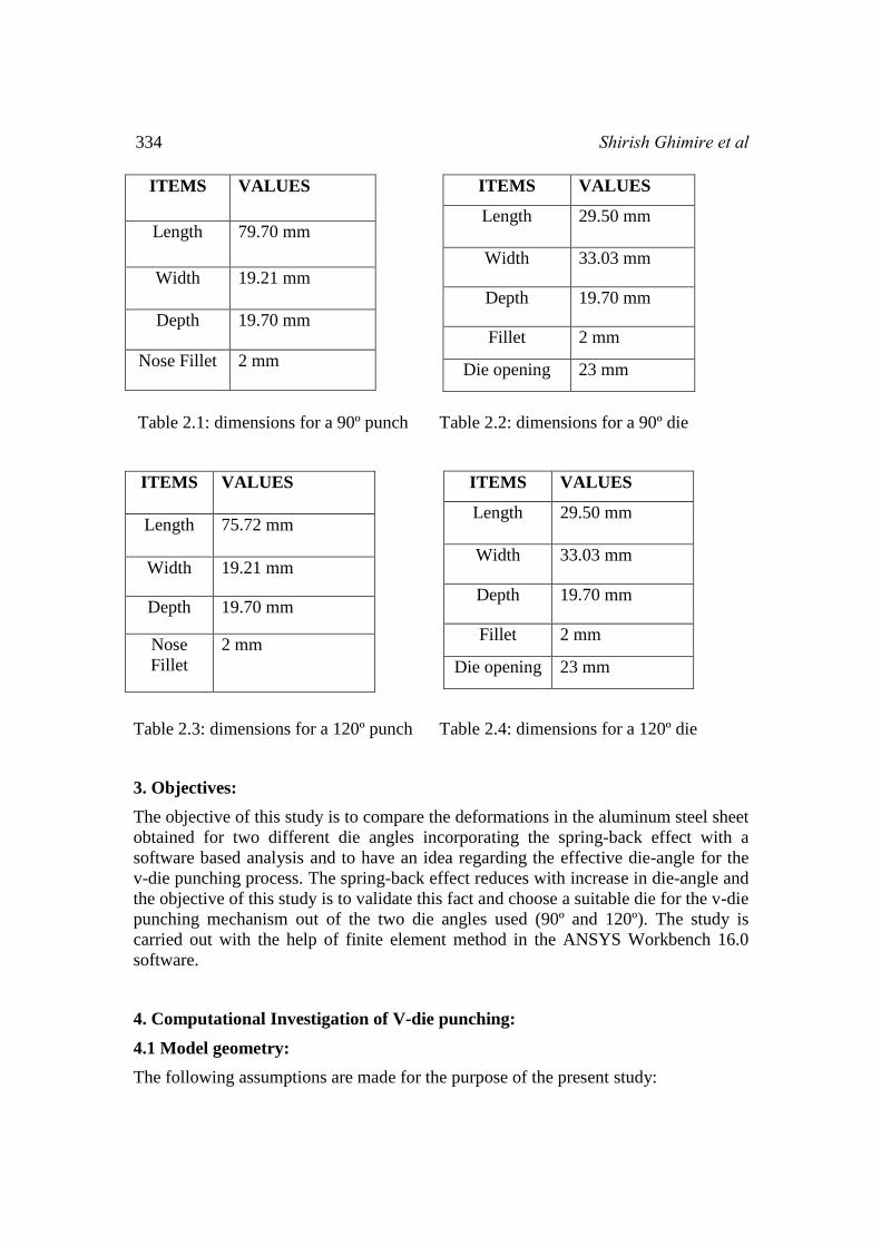
In this study the Cartesian co-ordinate system is placed at the midpoint of the sheet
metal We have done our study based on this co-ordinate system The positive and
negative sign only indicates the position of the element with respect to this coordinate
system
Fig 41 V-die punch model in Ansys 160
42 FEM (Finite Element Method)
Numerical methods provide a general tool to analyze arbitrary geometries and loading
conditions Among this numerical analysis FEM (Finite Element Analysis) is used
most extensively [25] This kind of analysis requires the generation of the large
amount of data to obtain the more accurate results and consumes huge investment of
the computer resources and engineering time [26] FEM is the good choice to analyze
the sheet metal punching processes since it helps to eliminate the need for the time
and cost consuming experiments to optimize the parameters [27] The finite element
method gives an appropriate solution with an accuracy that mainly depends on the
type of element chosen and the number of elements We used the FEM to simulate the
punching process in ANSYS 150 which is capable of solving the nonlinear behavior
of the materials deformations and stress-strain accurately
336 Shirish Ghimire et al
43 Meshing
To perform the finite element method correctly we have to divide the metal sheet into
very small elements ie mesh elements and then the simulation is done respectively
There are different types of method to perform the meshing process like Tetrahedron
Hex dominant Sweep Multizone etc We in this study choose the Tetrahedron
method In this study 16804 elements and 31142 nodes are considered The details of
the meshing process are shown the figure below To get the accurate result we divide
the sheet metal into mesh element of sizing 1mm
Table 43 Meshing
ELEMENTS VALUES
Meshing method Tetrahedron
Elements 16804
Nodes 31142
Mesh element sizing 1 mm
Minimum edge
length
05 mm
Fig 43 Meshed model V-die punch model
Finite Element Analysis of an Aluminium Alloy Sheet in a V-Die Punchhellip 337
44 Simulation
441 Result and discussion for 90 ordm die
The Total deformation and the directional deformations along x y and z axes are
shown in the following fig The analysis is performed by considering two nonlinear
metal sheets of 5mm thickness when subjected to a load of 550 MPa at STP
Fig 4411 total deformation for a 90ordm die
Fig 4412 directional deformation for 90 ordm die
Time is plotted along x axis and the variation of the total deformation is plotted along
the y- axis From this graphs it is observed that the total deformation for both the
metals increases almost uniformly and itrsquos parabolic in nature
Table 441 total and directional deformation for a 90 ordm die
Die-angle ITEMS VALUES
90 ordm
1 Total deformation 10048 mm (max) 038139 mm
(min)
2 Directional deformation 10046 mm (max) 038129 mm
(min)
Fig 4411 total deformation for 90
ordm die
338 Shirish Ghimire et al
442 Result and discussion for 120 ordm die
In a similar way the deformation and the directional deformations for 120 ordm die along
x y and z axes are shown in the following fig The analysis is performed by
considering two nonlinear metal sheets of 5mm thickness when subjected to a load of
550 MPa at STP
Fig 4421 Total deformation for 120ordm die
Fig 4422 Directional deformation for 120 ordm die
Time is plotted along x axis and the variation of the total deformation is plotted along
the y- axis From this graph it is observed that the total deformation for both the
metals increases almost uniformly and itrsquos parabolic in nature
Table 442 total and directional deformation for a 120 ordm die
Die-angle ITEMS VALUES
120 ordm
1 Total deformation 61095 mm (max) 018962 mm
(min)
2 Directional deformation 61094 mm (max) 018959 mm
(min)
Finite Element Analysis of an Aluminium Alloy Sheet in a V-Die Punchhellip 339
44 Conclusion
From this analysis we can see that the total deformation on the sheet metal for 90 ordm
die is greater than that in case of 120 ordm die Total deformation on the sheet metal for a
90 ordm die is 10048 mm (max) and that when die angle equals to 120 ordm is 61095 mm
(max) Similarly the directional deformation on the sheet metal for a 90 ordm die is
10046 mm (max) in the vertical direction and that when using a 120 ordm die is 61094
mm (max) Hence we see that the deformation in the 90 ordm die is much greater than
that in the 120 ordm die After removal of the tool the final directional deformation on the
metal sheet for a 90 ordm die is 80578 mm and that when using a 120 ordm die is 51489 mm
For the 90 ordm die a reduction of 19882 mm for directional deformation from the
initials and a reduction of 09605mm for the 120 ordm die is obtained Hence we
understand that the phenomena of spring back produces different effects for different
die anglesWith the increase in die-angle the spring-back effect is reduced In the
present study it is found that the spring-back effect for 120 ordm die is lesser than that for
the 90 ordm die which validates the concept of spring back phenomena in the context of
variable die angles In addition to that the spring-back effect being an unwanted
effect deformation in the 120 ordm die is the desired deformation and hence 120 ordm die
would be the preferred one
Table 44 Conclusion Table
ITEM NAME
For 90 ordm die For 120 ordm die
Maximum Total Deformation 10048 mm 61095 mm
Maximum Directional Deformation along y-axis
(initial)
10046 mm 61094 mm
Directional Deformation with Spring-back effect 80578 mm 51489 mm
Reduction in Directional Deformation 19882 mm 09605 mm
45 FUTURE SCOPE OF WORK
Further investigation is needed to explore more parameters and operating conditions
to develop a general model for more material types by using the combination of
various techniques A combination of techniques can be used in order to achieve a
higher level of verification and to reduce the cost of the necessary experimental effort
It is recommended to experimentally perform the punching process that combines the
optimal set of parameters and monitor its output quality
340 Shirish Ghimire et al
REFERENCES
[1] FW Timmerbil Werkstatt Maschin 46 (1956) 58ndash66
[2] httpsenwikipediaorgwikiPunching
[3] F Faura J Loacute pez C Luacute is MA Sebastiaacuten and Blanking of stainless
steel tool life equation model in T Altan (Ed) Advanced Technology of
Plasticity vol II Columbus OH 1996 pp 655ndash663
[4] Russell biagi hilary bart smithldquoimperfection sensetivity of pyramidal core
sandwich structurerdquo international journal of solids and structures 44 (2007)
4690ndash4706
[5] Sisheng yang xiang ling yangyan zheng rongbiao ma ldquocreep life analysis by
an energy model of small punch
creeptestrdquojournalhomepagewwwelseviercomlocatematdes
[6] Wen chun jiang b yang bywang h chen jm gong ldquoexperimental and
numerical study on the residual stress in a lattic truss sandwich atructure
effect of geometrical dimension of punching dierdquojournal homepage
wwwelseviercomlocatematdes
[7] Pusit mitsomwang shigeru nagasawardquoeffect of mechanical conditions on
cutting characteristics of polycarbonate sheet subjected to straight punchdie
shearingrdquo (ICTP) 2014 19-24 October 2014 Nagoya Congress Center
Nagoya Japan Procedia Engineering 81 ( 2014 ) 1145 ndash 1150
[8] Soumya subramoniana taylan altanan bogdan ciocirlanb craig campbellb
ldquooptimum selection of variable punch-die clearance to improve tool life in
blanking non-symmetric shapesrdquo (IJMTM) journal homepage
wwwelseviercomlocateijmactool
[9] E falconnet jchambert h makich g monteil ldquoprediction of abrasive punch
wear in copper alloy thin
sheetblankingrdquojournalhomepagewwwelseviercomlocatewear
[10] L komgrit h hamasaki r hino fyoshida ldquoelimination of springback of high
strength steel sheet by using additional bending with counter punchrdquo
(JMPT)journalhomepagewwwelseviercomlocatejmatprotec
[11] Debayan das saurav rajgadia anush karki ankit basnet pawan jaiswal rakesh
jaiswal anupam raj jha rabindra nath barman ldquodesign and finite element
analysis of connecting rod using solidworks and ansys workbenchrdquo (ijreat)
Volume 3 Issue 4 Aug-Sept 2015 ISSN 2320 ndash 8791
[12] International Journal of Emerging Technology and Advanced Engineering
wwwijetaecom (ISSN 2250-2459 Volume 2 Issue 7 July 2012)
Experimental Evaluation of Effect of Die Angle on Hardness and Surface
Finish of Cold Forward Extrusion of Aluminum G A ChaudhariSR
Andhale NG Patil
Finite Element Analysis of an Aluminium Alloy Sheet in a V-Die Punchhellip 341
[13] Effect of die angle on the deformation texture of copper processed by equal
channel angular extrusion WH Huang a L Chang b PW Kao a CP
Chang wwwelseviercomlocatemsea Materials Science and Engineering
A307 (2001) 113ndash118
[14] J W Pilarczyk J Markowski FEM Analysis Of Effect Of Die Angle On
Strain And Stress State In Process Of Drawing Of Steel For Prestressed
Concrete
[15] Extrusion Characteristics Dependence of Wrought Aluminium Alloy on
Extrusion Variables S O Adeosun Akpan E I Gbenebor O P American
Journal of Materials Science 2013 3(4) 77-83 DOI
105923jmaterials2013030403
[16] Investigating Springback effect in U-Die Bending Process by varying different
Parameters Jaydeep R Shah12 S K Sharma1 B C Patel$1 Associate
professor Mechanical Department $Assistant Professor Mechanical
Department Research Scholar Mechanical Department
[17] Creep and anelasticity in the springback of aluminum JF Wang a RH
Wagoner a WD Carden b DK Matlock c F Barlat Elsevier
International journal of plasticity
[18] Mechanical Behavior and Springback Study of an Aluminum Alloy inWarm
Forming Conditions H Laurent1 2 J Coumler1 2 R Gr`eze1 P Y Manach1
A Andrade-Campos3 M C Oliveira2 and L FMenezes2 International
Scholarly Research Network ISRN Mechanical Engineering Volume 2011
Article ID 381615
[19] A Comprehensive Review of Experimental Approaches Used in the
Measurement of Springback 1AB Abdullah 2SM Sapuan 1Z Samad and
2NA Aziz
[20] Elimination of springback of high-strength steel sheet by usingadditional
bending with counter punchL Komgritablowast H Hamasakic R Hinoc F
Yoshidac Journal of Materials Processing Technology 229 (2016) 199ndash206
elsevier
[21] httpwwwthefabricatorcomarticlebendingbending-basics-why-do-die-
angles-changer
[22] Prediction of coefficient of friction for Aluminum Billet Ajay Kumar Kaviti
Om Prakash and P Vishwanath Kumar Scholars Research Library Archives
of Applied Science Research 2011 3 (4)328-335
[23] The effect of friction coefficient on punch load and thickness reduction in
deep drawing process Sadık Olguner A Tolga Bozdana INTERNATIONAL
JOURNAL OF MATERIALS Volume 3 2016
342 Shirish Ghimire et al
[24] Theoretical Investigation of Friction at DieBillet Interface in Hydrostatic
Extrusion of Commercially Pure Aluminum PANKAJ TOMAR SCIENCE
DIRECT
[25] An Application of Finite Element Method and Design of Experiments in the
Optimization of Sheet Metal Blanking Process Emad Al-Momani Ibrahim
Rawabdeh
[26] Haydn ng wadley norman a fleck anthony g evans ldquofabrication and
atructural performance of periodic cellular metal sandwich structuresrdquo
Composite scienceand technology 63 (2003) 2331-2343
[27] S Maiti A Ambekar U Singh P Date and K Narasimhan ldquoAssessment of
influence of some process parameters on sheet metal blankingrdquo Journal of
Materials Processing Technology Vol 102 2000 249-256

332 Shirish Ghimire et al
1 Introduction
Blanking and punching are one of the oldest manufacturing operations Their
applications range from components of very light to heavy appliances and
machineries [1] Punching is a metal forming process that uses a punch press to force
a tool called a punch through the work piece to create a hole via shearing When a
specially shaped punch is used to create multiple usable parts from a sheet of material
the process is known as blanking [2]During blanking the part is subjected to
complex solicitations such as deformation hardening and crack initiation and
propagation The theoretical modeling of such processes is very difficult due to the
complexity in describing the different stages of the whole shearing process starting
with the elastic stage and ending with the total separation of the sheet metal [3] Small
punch test (SPT) Ball punch Test Disk Bend test as well as Shear Punch Test [4-9]
are the techniques developing to characterize the mechanical behavior of small
specimens The concept of the small V-die punching is based on placing a thin metal
sheet specimen on the die and then the v shaped punch is applied to get the desired
shape In this process the feed is applied to the metal sheet horizontally and the
punching is done vertically In order to get the stable punching and the good punching
edge quality of the al alloy and stainless steel alloy sheets [10] it is necessary to
choose a narrow punch-die clearance and the heat sheet before punching Reducing
the clearance my increase the bright zone and also reduce the fracture zone as well as
the fracture angle but if the clearance is reduced the punching force and the tooling
wear increases [11] An experimental investigation had been carried out to study the
effect of die angle on the quality of extruded product ie surface finish and hardness
of cold extruded aluminum The die angles used were 30 45 and 60 ordms [12] Similarly
deformation in copper was observed using ECAE technique under variable die angles
The die angles used were 90 ordm and 120 ordm for this research [13] J W PILARCZYK
and J MARKOWSKI studied the effect of die angle on strain and stress state in
process of drawing of steel for pre-stressed concrete keeping 8 12 and 18 ordm dies for
the process [14] Similarly five different die angles (15 30 45 60 and 90) were used
to investigate the extrusion behavior of wrought aluminum alloys [15] Spring-back is
a geometric change that a sheet metal experiences after it gets rid of the tool forces in
a punching process Spring-back effect results in slight displacement of the sheet
metal in the direction of the return stroke of the punch Spring-back has a very
significant role in sheet metal bending process It leads to some geometric changes in
the product A research work was carried out for reflecting the different parameters on
spring-back in U-die bending of different materials with different sheet thickness and
tip radius [16]If not correctly predicted and compensated for spring-back will cause
the final part shape to deviate from design specifications and to create assembly
problems [17] H Laurent conducted the Spring-back study of aluminum alloy in
warm forming conditions A split-ring test was used to analyze the influence of
temperature during forming over Spring-back The obtained experimental results were
compared to the numerical simulations [18] A research was done earlier which
studied the spring-back effect in both V-die and U-die punching mechanism Spring-
Finite Element Analysis of an Aluminium Alloy Sheet in a V-Die Punchhellip 333
back can only be controlled and minimized but quite difficult to be eliminated [19]
However a new technique was proposed to eliminate the spring-back of high-strength
steel (HSS) sheets in the U-bending process In this technique spring-back is
eliminated using counter-punch [20] The reason die angle change is to compensate
for spring-back [21] Friction plays a major role in metal forming processes because
of its direct interaction with die and work-piece Friction creates obstacles in the free
movement and significantly affects the deformation of the work-piece The co-
efficient of friction should be specified at the die-work interface [22] It was also seen
that the punch load increases significantly with the increase in co-efficient of friction
[23] PANKAJ TOMAR also investigated the effect of friction at the die-billet
interface for a commercially pure aluminum However this study was done for
hydrostatic extrusion of aluminum [24] In this analysis we are considering that metal
sheets are homogeneous and neglecting the surface roughness
2 Design Specification
To carry out this study a 5mm thick plate of aluminum alloy was used as the sheet
material Structural Steel was used as the preferred material for both die and punch
The dimensions used in the study for the die and the punch are tabulated below
334 Shirish Ghimire et al
ITEMS VALUES
Length 2950 mm
Width 3303 mm
Depth 1970 mm
Fillet 2 mm
Die opening 23 mm
Table 21 dimensions for a 90ordm punch Table 22 dimensions for a 90ordm die
ITEMS VALUES
Length 2950 mm
Width 3303 mm
Depth 1970 mm
Fillet 2 mm
Die opening 23 mm
Table 23 dimensions for a 120ordm punch Table 24 dimensions for a 120ordm die
3 Objectives
The objective of this study is to compare the deformations in the aluminum steel sheet
obtained for two different die angles incorporating the spring-back effect with a
software based analysis and to have an idea regarding the effective die-angle for the
v-die punching process The spring-back effect reduces with increase in die-angle and
the objective of this study is to validate this fact and choose a suitable die for the v-die
punching mechanism out of the two die angles used (90ordm and 120ordm) The study is
carried out with the help of finite element method in the ANSYS Workbench 160
software
4 Computational Investigation of V-die punching
41 Model geometry
The following assumptions are made for the purpose of the present study
ITEMS VALUES
Length 7970 mm
Width 1921 mm
Depth 1970 mm
Nose Fillet 2 mm
ITEMS VALUES
Length 7572 mm
Width 1921 mm
Depth 1970 mm
Nose
Fillet
2 mm
Finite Element Analysis of an Aluminium Alloy Sheet in a V-Die Punchhellip 335
To simplify the process we have taken the steady loading condition under plain
strain condition since in the usual blanking operation the punch-die clearance is
very small
It is a quasi-static process and hence the effect of plain strain rate is neglected
The sheet metal is considered as the nonlinear plastic material while the die and
punch is the rigid bodies
In this case we have compared the mechanical properties of the aluminium and
stainless steel so our focus is only the simulation of the sheet metal So we
neglect the properties of punch amp die
In this study the Cartesian co-ordinate system is placed at the midpoint of the sheet
metal We have done our study based on this co-ordinate system The positive and
negative sign only indicates the position of the element with respect to this coordinate
system
Fig 41 V-die punch model in Ansys 160
42 FEM (Finite Element Method)
Numerical methods provide a general tool to analyze arbitrary geometries and loading
conditions Among this numerical analysis FEM (Finite Element Analysis) is used
most extensively [25] This kind of analysis requires the generation of the large
amount of data to obtain the more accurate results and consumes huge investment of
the computer resources and engineering time [26] FEM is the good choice to analyze
the sheet metal punching processes since it helps to eliminate the need for the time
and cost consuming experiments to optimize the parameters [27] The finite element
method gives an appropriate solution with an accuracy that mainly depends on the
type of element chosen and the number of elements We used the FEM to simulate the
punching process in ANSYS 150 which is capable of solving the nonlinear behavior
of the materials deformations and stress-strain accurately
336 Shirish Ghimire et al
43 Meshing
To perform the finite element method correctly we have to divide the metal sheet into
very small elements ie mesh elements and then the simulation is done respectively
There are different types of method to perform the meshing process like Tetrahedron
Hex dominant Sweep Multizone etc We in this study choose the Tetrahedron
method In this study 16804 elements and 31142 nodes are considered The details of
the meshing process are shown the figure below To get the accurate result we divide
the sheet metal into mesh element of sizing 1mm
Table 43 Meshing
ELEMENTS VALUES
Meshing method Tetrahedron
Elements 16804
Nodes 31142
Mesh element sizing 1 mm
Minimum edge
length
05 mm
Fig 43 Meshed model V-die punch model
Finite Element Analysis of an Aluminium Alloy Sheet in a V-Die Punchhellip 337
44 Simulation
441 Result and discussion for 90 ordm die
The Total deformation and the directional deformations along x y and z axes are
shown in the following fig The analysis is performed by considering two nonlinear
metal sheets of 5mm thickness when subjected to a load of 550 MPa at STP
Fig 4411 total deformation for a 90ordm die
Fig 4412 directional deformation for 90 ordm die
Time is plotted along x axis and the variation of the total deformation is plotted along
the y- axis From this graphs it is observed that the total deformation for both the
metals increases almost uniformly and itrsquos parabolic in nature
Table 441 total and directional deformation for a 90 ordm die
Die-angle ITEMS VALUES
90 ordm
1 Total deformation 10048 mm (max) 038139 mm
(min)
2 Directional deformation 10046 mm (max) 038129 mm
(min)
Fig 4411 total deformation for 90
ordm die
338 Shirish Ghimire et al
442 Result and discussion for 120 ordm die
In a similar way the deformation and the directional deformations for 120 ordm die along
x y and z axes are shown in the following fig The analysis is performed by
considering two nonlinear metal sheets of 5mm thickness when subjected to a load of
550 MPa at STP
Fig 4421 Total deformation for 120ordm die
Fig 4422 Directional deformation for 120 ordm die
Time is plotted along x axis and the variation of the total deformation is plotted along
the y- axis From this graph it is observed that the total deformation for both the
metals increases almost uniformly and itrsquos parabolic in nature
Table 442 total and directional deformation for a 120 ordm die
Die-angle ITEMS VALUES
120 ordm
1 Total deformation 61095 mm (max) 018962 mm
(min)
2 Directional deformation 61094 mm (max) 018959 mm
(min)
Finite Element Analysis of an Aluminium Alloy Sheet in a V-Die Punchhellip 339
44 Conclusion
From this analysis we can see that the total deformation on the sheet metal for 90 ordm
die is greater than that in case of 120 ordm die Total deformation on the sheet metal for a
90 ordm die is 10048 mm (max) and that when die angle equals to 120 ordm is 61095 mm
(max) Similarly the directional deformation on the sheet metal for a 90 ordm die is
10046 mm (max) in the vertical direction and that when using a 120 ordm die is 61094
mm (max) Hence we see that the deformation in the 90 ordm die is much greater than
that in the 120 ordm die After removal of the tool the final directional deformation on the
metal sheet for a 90 ordm die is 80578 mm and that when using a 120 ordm die is 51489 mm
For the 90 ordm die a reduction of 19882 mm for directional deformation from the
initials and a reduction of 09605mm for the 120 ordm die is obtained Hence we
understand that the phenomena of spring back produces different effects for different
die anglesWith the increase in die-angle the spring-back effect is reduced In the
present study it is found that the spring-back effect for 120 ordm die is lesser than that for
the 90 ordm die which validates the concept of spring back phenomena in the context of
variable die angles In addition to that the spring-back effect being an unwanted
effect deformation in the 120 ordm die is the desired deformation and hence 120 ordm die
would be the preferred one
Table 44 Conclusion Table
ITEM NAME
For 90 ordm die For 120 ordm die
Maximum Total Deformation 10048 mm 61095 mm
Maximum Directional Deformation along y-axis
(initial)
10046 mm 61094 mm
Directional Deformation with Spring-back effect 80578 mm 51489 mm
Reduction in Directional Deformation 19882 mm 09605 mm
45 FUTURE SCOPE OF WORK
Further investigation is needed to explore more parameters and operating conditions
to develop a general model for more material types by using the combination of
various techniques A combination of techniques can be used in order to achieve a
higher level of verification and to reduce the cost of the necessary experimental effort
It is recommended to experimentally perform the punching process that combines the
optimal set of parameters and monitor its output quality
340 Shirish Ghimire et al
REFERENCES
[1] FW Timmerbil Werkstatt Maschin 46 (1956) 58ndash66
[2] httpsenwikipediaorgwikiPunching
[3] F Faura J Loacute pez C Luacute is MA Sebastiaacuten and Blanking of stainless
steel tool life equation model in T Altan (Ed) Advanced Technology of
Plasticity vol II Columbus OH 1996 pp 655ndash663
[4] Russell biagi hilary bart smithldquoimperfection sensetivity of pyramidal core
sandwich structurerdquo international journal of solids and structures 44 (2007)
4690ndash4706
[5] Sisheng yang xiang ling yangyan zheng rongbiao ma ldquocreep life analysis by
an energy model of small punch
creeptestrdquojournalhomepagewwwelseviercomlocatematdes
[6] Wen chun jiang b yang bywang h chen jm gong ldquoexperimental and
numerical study on the residual stress in a lattic truss sandwich atructure
effect of geometrical dimension of punching dierdquojournal homepage
wwwelseviercomlocatematdes
[7] Pusit mitsomwang shigeru nagasawardquoeffect of mechanical conditions on
cutting characteristics of polycarbonate sheet subjected to straight punchdie
shearingrdquo (ICTP) 2014 19-24 October 2014 Nagoya Congress Center
Nagoya Japan Procedia Engineering 81 ( 2014 ) 1145 ndash 1150
[8] Soumya subramoniana taylan altanan bogdan ciocirlanb craig campbellb
ldquooptimum selection of variable punch-die clearance to improve tool life in
blanking non-symmetric shapesrdquo (IJMTM) journal homepage
wwwelseviercomlocateijmactool
[9] E falconnet jchambert h makich g monteil ldquoprediction of abrasive punch
wear in copper alloy thin
sheetblankingrdquojournalhomepagewwwelseviercomlocatewear
[10] L komgrit h hamasaki r hino fyoshida ldquoelimination of springback of high
strength steel sheet by using additional bending with counter punchrdquo
(JMPT)journalhomepagewwwelseviercomlocatejmatprotec
[11] Debayan das saurav rajgadia anush karki ankit basnet pawan jaiswal rakesh
jaiswal anupam raj jha rabindra nath barman ldquodesign and finite element
analysis of connecting rod using solidworks and ansys workbenchrdquo (ijreat)
Volume 3 Issue 4 Aug-Sept 2015 ISSN 2320 ndash 8791
[12] International Journal of Emerging Technology and Advanced Engineering
wwwijetaecom (ISSN 2250-2459 Volume 2 Issue 7 July 2012)
Experimental Evaluation of Effect of Die Angle on Hardness and Surface
Finish of Cold Forward Extrusion of Aluminum G A ChaudhariSR
Andhale NG Patil
Finite Element Analysis of an Aluminium Alloy Sheet in a V-Die Punchhellip 341
[13] Effect of die angle on the deformation texture of copper processed by equal
channel angular extrusion WH Huang a L Chang b PW Kao a CP
Chang wwwelseviercomlocatemsea Materials Science and Engineering
A307 (2001) 113ndash118
[14] J W Pilarczyk J Markowski FEM Analysis Of Effect Of Die Angle On
Strain And Stress State In Process Of Drawing Of Steel For Prestressed
Concrete
[15] Extrusion Characteristics Dependence of Wrought Aluminium Alloy on
Extrusion Variables S O Adeosun Akpan E I Gbenebor O P American
Journal of Materials Science 2013 3(4) 77-83 DOI
105923jmaterials2013030403
[16] Investigating Springback effect in U-Die Bending Process by varying different
Parameters Jaydeep R Shah12 S K Sharma1 B C Patel$1 Associate
professor Mechanical Department $Assistant Professor Mechanical
Department Research Scholar Mechanical Department
[17] Creep and anelasticity in the springback of aluminum JF Wang a RH
Wagoner a WD Carden b DK Matlock c F Barlat Elsevier
International journal of plasticity
[18] Mechanical Behavior and Springback Study of an Aluminum Alloy inWarm
Forming Conditions H Laurent1 2 J Coumler1 2 R Gr`eze1 P Y Manach1
A Andrade-Campos3 M C Oliveira2 and L FMenezes2 International
Scholarly Research Network ISRN Mechanical Engineering Volume 2011
Article ID 381615
[19] A Comprehensive Review of Experimental Approaches Used in the
Measurement of Springback 1AB Abdullah 2SM Sapuan 1Z Samad and
2NA Aziz
[20] Elimination of springback of high-strength steel sheet by usingadditional
bending with counter punchL Komgritablowast H Hamasakic R Hinoc F
Yoshidac Journal of Materials Processing Technology 229 (2016) 199ndash206
elsevier
[21] httpwwwthefabricatorcomarticlebendingbending-basics-why-do-die-
angles-changer
[22] Prediction of coefficient of friction for Aluminum Billet Ajay Kumar Kaviti
Om Prakash and P Vishwanath Kumar Scholars Research Library Archives
of Applied Science Research 2011 3 (4)328-335
[23] The effect of friction coefficient on punch load and thickness reduction in
deep drawing process Sadık Olguner A Tolga Bozdana INTERNATIONAL
JOURNAL OF MATERIALS Volume 3 2016
342 Shirish Ghimire et al
[24] Theoretical Investigation of Friction at DieBillet Interface in Hydrostatic
Extrusion of Commercially Pure Aluminum PANKAJ TOMAR SCIENCE
DIRECT
[25] An Application of Finite Element Method and Design of Experiments in the
Optimization of Sheet Metal Blanking Process Emad Al-Momani Ibrahim
Rawabdeh
[26] Haydn ng wadley norman a fleck anthony g evans ldquofabrication and
atructural performance of periodic cellular metal sandwich structuresrdquo
Composite scienceand technology 63 (2003) 2331-2343
[27] S Maiti A Ambekar U Singh P Date and K Narasimhan ldquoAssessment of
influence of some process parameters on sheet metal blankingrdquo Journal of
Materials Processing Technology Vol 102 2000 249-256
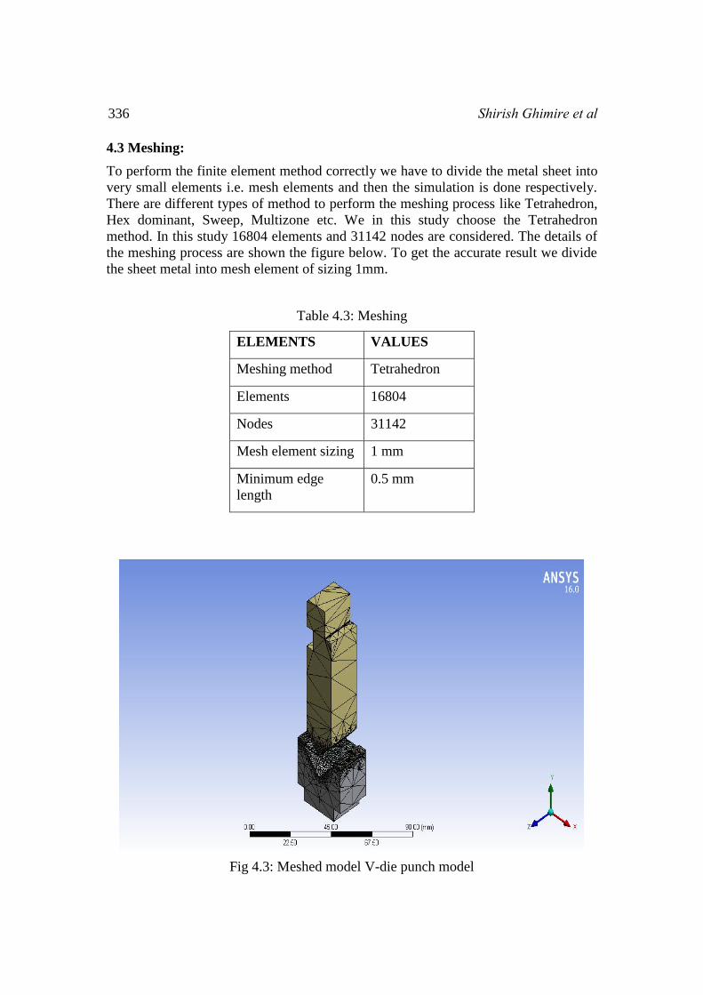
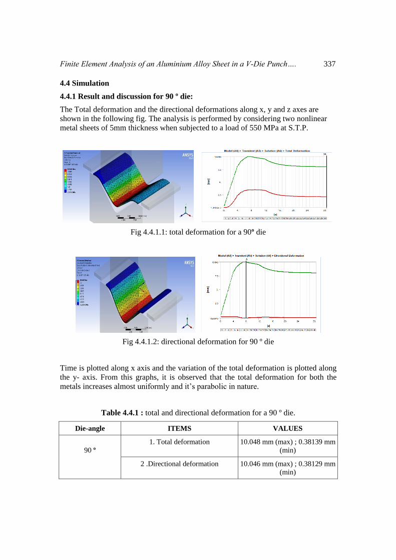
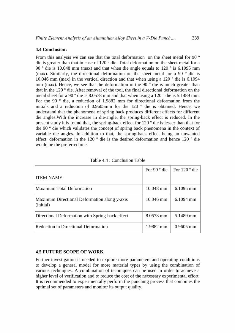