finite element analysis based thermal-mechanical stress ... aging and...
TRANSCRIPT

ANL/LWRS-16/01
Finite Element Analysis Based Thermal-Mechanical Stress Analysis of PWR Pressure Vessel with/without Pre-existing Crack to Study the Effect of Cyclic Hardening Material Properties Under Grid Load Following Mode: An Interim Report
Nuclear Engineering Division

About Argonne National Laboratory Argonne is a U.S. Department of Energy laboratory managed by UChicago Argonne, LLC
under contract DE-AC02-06CH11357. The Laboratory’s main facility is outside Chicago,
at 9700 South Cass Avenue, Argonne, Illinois 60439. For information about Argonne
and its pioneering science and technology programs, see www.anl.gov.
DOCUMENT AVAILABILITY
Online Access: U.S. Department of Energy (DOE) reports produced after 1991 and a
growing number of pre-1991 documents are available free via DOE’s SciTech Connect
(http://www.osti.gov/scitech/)
Reports not in digital format may be purchased by the public from the National Technical Information Service (NTIS): U.S. Department of Commerce
National Technical Information Service
5301 Shawnee Rd
Alexandria, VA 22312
www.ntis.gov Phone: (800) 553-NTIS (6847) or (703) 605-6000
Fax: (703) 605-6900
Email: [email protected]
Reports not in digital format are available to DOE and DOE contractors from the Office of Scientific and Technical Information (OSTI): U.S. Department of Energy
Office of Scientific and Technical Information
P.O. Box 62
Oak Ridge, TN 37831-0062
www.osti.gov Phone: (865) 576-8401
Fax: (865) 576-5728
Email: [email protected]
Disclaimer This report was prepared as an account of work sponsored by an agency of the United States Government. Neither the United States
Government nor any agency thereof, nor UChicago Argonne, LLC, nor any of their employees or officers, makes any warranty, express
or implied, or assumes any legal liability or responsibility for the accuracy, completeness, or usefulness of any information, apparatus,
product, or process disclosed, or represents that its use would not infringe privately owned rights. Reference herein to any specific
commercial product, process, or service by trade name, trademark, manufacturer, or otherwise, does not necessarily constitute or imply
its endorsement, recommendation, or favoring by the United States Government or any agency thereof. The views and opinions of
document authors expressed herein do not necessarily state or reflect those of the United States Government or any agency thereof,
Argonne National Laboratory, or UChicago Argonne, LLC.

ANL/LWRS-16/01
Finite Element Analysis Based Thermal-Mechanical Stress Analysis of PWR Pressure Vessel with/without Pre-existing Crack to Study the Effect of Cyclic Hardening Material Properties under Grid Load Following Mode: An Interim Report
Subhasish Mohanty, William Soppet, Saurin Majumdar, and Ken Natesan
Nuclear Engineering Division, Argonne National Laboratory March 2016

This page intentionally left blank

Finite Element Analysis Based Thermal-Mechanical Stress Analysis of PWR Pressure Vessel with/without Pre-existing Crack to Study the Effect of Cyclic Hardening Material Properties under Grid Load Following Mode: An Interim Report March 2016
ANL/LWRS-16/01
i
ABSTRACT
This report provides an update on an assessment of environmentally assisted fatigue for light water reactor components under extended service conditions. This report is a deliverable in March 2016 under the work package for environmentally assisted fatigue under DOE’s Light Water Reactor Sustainability program. In a September 2015 report we presented tensile and fatigue test data and related hardening material properties for 508 low-alloys steel (LAS) base metal, and other reactor metals. In the this report, we present thermal-mechanical stress analysis of RPV and its hot leg and cold leg nozzles based on some of those estimated material properties. We also present thermal and thermal-mechanical stress analysis models under reactor heat-up, cool-down and grid load following conditions. We present analysis results of RPV with and without presence of preexisting crack (with axial or circumferential crack). In addition, we provide validation stress analysis models based on ANL conducted tensile and fatigue experiments.

Finite Element Analysis Based Thermal-Mechanical Stress Analysis of PWR Pressure Vessel with/without Pre-existing Crack to Study the Effect of Cyclic Hardening Material Properties under Grid Load Following Mode: An Interim Report March 2016
ANL/LWRS-16/01 ii
This page intentionally left blank

Finite Element Analysis Based Thermal-Mechanical Stress Analysis of PWR Pressure Vessel with/without Pre-existing Crack to Study the Effect of Cyclic Hardening Material Properties under Grid Load Following Mode: An Interim Report March 2016
ANL/LWRS-16/01
iii
TABLE OF CONTENTS Finite Element Analysis Based Thermal-Mechanical Stress Analysis of PWR Pressure Vessel with/without Pre-existing Crack to Study the Effect of Cyclic Hardening Material Properties under Grid Load Following Mode: An Interim Report i
ABSTRACT i
Table of Contents iii
List of Figures iv
List of TABLES vii
Abbreviations viii
Acknowledgments ix
1 Introduction 1
2 Finite Element Model of Reactor Pressure Vessel and Nozzles 2
3 Temperature-Pressure Boundary Conditions under Heat-Up, Cool-Down and Grid Load Following 6
3.1 Reactor Heat up & Cool Down ....................................................................................... 6 3.2 Reactor Power Operation under Load Following ........................................................... 8
4 Heat Transfer Analysis of RPV and Nozzles 13
4.1 Thermal Material Properties ......................................................................................... 13 4.2 Thermal Analysis Results ............................................................................................. 14
4.2.1 OD surface ambient condition and with ID surface maximum film coefficient of 616.76 W/m2-K 14 4.2.2 OD surface ambient condition with ID surface maximum film coefficient 18502.8 W/m2-K 16 4.2.3 OD surface insulated condition with ID surface maximum film coefficient 18502.8 W/m2-K 19
5 Material Property for Structural Analysis 22
6 Stress Analysis of Laboratory Specimen under Isothermal Fatigue Loading 28
6.1 FE Model of T08 Tensile Test ...................................................................................... 28 6.2 FE Model of EN-F20 Fatigue Test ............................................................................... 29
7 Thermal-Mechanical Stress Analysis of RPV and Nozzles without Preexisting Crack 32
8 XFEM Modeling and Thermal-Mechanical Stress Analysis of RPV and Nozzles with Preexisting Crack 40
9 Summary and Future Study 46

Finite Element Analysis Based Thermal-Mechanical Stress Analysis of PWR Pressure Vessel with/without Pre-existing Crack to Study the Effect of Cyclic Hardening Material Properties under Grid Load Following Mode: An Interim Report March 2016
ANL/LWRS-16/01 iv
LIST OF FIGURES
Figure 2. 1 RPV and its nozzle solid model................................................................................ 2 Figure 2. 2 RPV and its nozzle FE mesh. ................................................................................... 3 Figure 2. 3 Solid model and FE mesh near the nozzle area. ....................................................... 4 Figure 2. 4 Example showing upper and lower internals of Zion reactor vessel [25] ................ 5 Figure 3. 1 Temperature profile during reactor heat-up and cool-down [28]. ........................... 7 Figure 3. 2 Pressure profile during reactor heat-up and cool-down [28]. ................................... 8 Figure 3. 3 Typical power history during a cycle in an Electricite de France (EDF) reactor
[2, 3]. ............................................................................................................................ 9 Figure 3. 4 Simplified percentage power time-history considered for present FE model. ....... 10 Figure 3. 5 Temperature relations with respect to percentage power in EDF reactor [3]. ........ 10 Figure 3. 6 Approximate estimated temperature histories in HL, CL and their average
during normal power operation under grid following mode. ..................................... 11 Figure 3. 7 Estimated temperature for HL and CL over entire reactor loading cycle. ............. 11 Figure 3. 8 Estimated combined pressure history during complete reactor loading cycle. ..... 12 Figure 4. 1 Temperature across CL nozzle thickness considering OD surface ambient
condition and with ID surface maximum film coefficient of 616.76 W/m2-K. ......... 14 Figure 4. 2 Temperature across HL nozzle thickness considering OD surface ambient
condition and with ID surface maximum film coefficient of 616.76 W/m2-K. ......... 15 Figure 4. 3 Temperature across RPV thickness considering OD surface ambient condition
and with ID surface maximum film coefficient of 616.76 W/m2-K. ......................... 15 Figure 4. 4 The OD and ID temperature spatial distribution at approximately 391.09 days
obtained through FE model considering OD surface ambient condition and with ID surface maximum film coefficient of 616.76 W/m2-K. ............................................. 16
Figure 4. 5 Temperature across CL nozzle thickness considering OD surface ambient condition and with ID surface maximum film coefficient of 18502.8 W/m2-K ........ 17
Figure 4. 6 Temperature across HL nozzle thickness considering OD surface ambient condition and with ID surface maximum film coefficient of 18502.8 W/m2-K ........ 17
Figure 4. 7 Temperature across RPV thickness considering OD surface ambient condition and with ID surface maximum film coefficient of 18502.8 W/m2-K ........................ 18
Figure 4. 8 The OD and ID temperature spatial distribution at approximately 391.09 days obtained through FE model considering OD surface ambient condition and with ID surface maximum film coefficient of 18502.8 W/m2-K ............................................ 18
Figure 4. 9 Temperature across CL nozzle thickness considering OD surface insulated condition and with ID surface maximum film coefficient of 18502.8 W/m2-K. ....... 19
Figure 4. 10 Temperature across HL nozzle thickness considering OD surface insulated condition and with ID surface maximum film coefficient of 18502.8 W/m2-K. ....... 20

Finite Element Analysis Based Thermal-Mechanical Stress Analysis of PWR Pressure Vessel with/without Pre-existing Crack to Study the Effect of Cyclic Hardening Material Properties under Grid Load Following Mode: An Interim Report March 2016
ANL/LWRS-16/01
v
Figure 4. 11 Temperature across RPV thickness considering OD surface insulated condition and with ID surface maximum film coefficient of 18502.8 W/m2-K ........................ 20
Figure 4. 12 The OD and ID temperature spatial distribution at approximately 391.09 days obtained through FE model considering OD surface insulated condition and with ID surface maximum film coefficient of 18502.8 W/m2-K. ...................................... 21
Figure 4. 13 Thickness variation of temperature for case discussed in a) section 4.2.2 and b) section 4.2.3. .............................................................................................................. 21
Figure 5. 1 Elastic modulus for 508 LAS base metal specimens fatigue tested under
different conditions [18]. ........................................................................................... 23 Figure 5. 2 Offset-strain (0.05%) yield limit stress for 508 LAS base metal specimens
fatigue tested under different conditions [18]. ........................................................... 24 Figure 5. 3 Nonlinear kinematic hardening parameter C1 (0.05% offset strain stress used as
yield stress) for 508 LAS base metal specimens fatigue tested under different conditions [18]. .......................................................................................................... 24
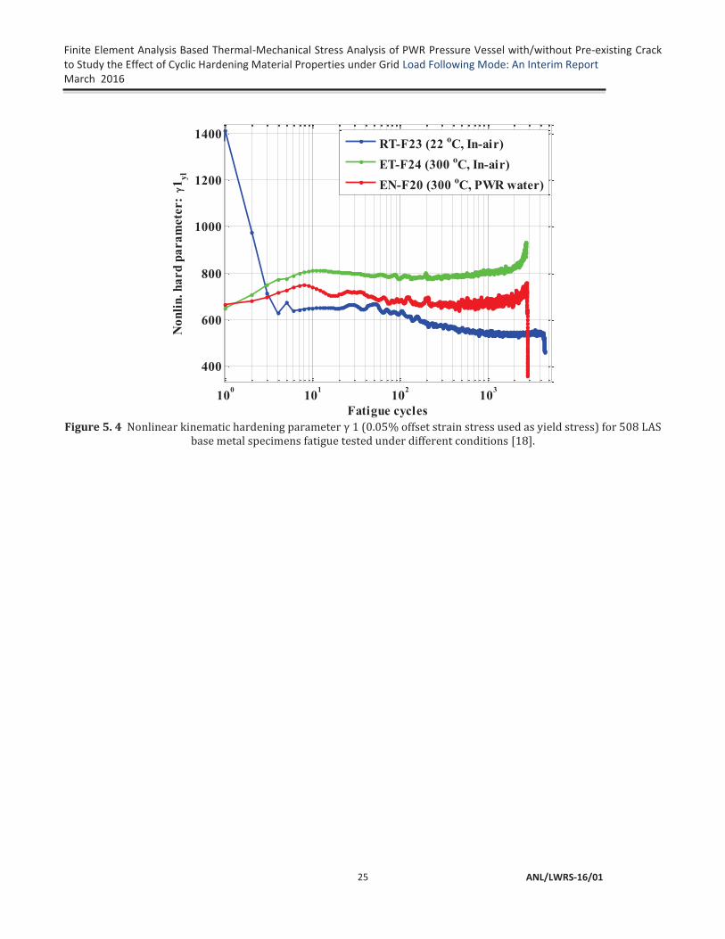
Figure 5. 4 Nonlinear kinematic hardening parameter γ 1 (0.05% offset strain stress used as yield stress) for 508 LAS base metal specimens fatigue tested under different conditions [18]. .......................................................................................................... 25
Figure 5. 5 Fracture toughness data (for 533 LAS) taken from [35]. ...................................... 26 Figure 5. 6 Estimated critical fracture energy for 533 LAS and used in the XFEM based
simulation. .................................................................................................................. 27 Table 6. 1 Experiment vs FE stress strain curve for T08 tensile test. ...................................... 28 Table 6. 2 Expt. Vs FE input for EN-F20 fatigue specimen. The FE simulation was
conducted over multiple steps (with peak amplitudes: S1, S2…S8). ........................ 29 Table 6. 3 FE simulated accumulated plastic strain profile at peak stroke amplitudes S1,
S2…S8 (shown in Figure 6.2). .................................................................................. 30 Table 6. 4 Expt. Vs FE simulated gage area strain. ................................................................. 30 Table 6. 5 Expt. Vs FE simulated gage area stress. ................................................................. 31 Figure 7. 1 In-air versus PWR-water condition thermal strain time-histories estimated at a
typical stress hotspot of CL nozzle. ........................................................................... 33 Figure 7. 2 In-air versus PWR-water condition thermal strain time-histories estimated at a
typical stress hotspot of HL nozzle. ........................................................................... 33 Figure 7. 3 In-air versus PWR-water condition thermal strain time-histories estimated at a
typical stress hotspot of RPV shell. ........................................................................... 34 Figure 7. 4 Temperature measured at gage center thermocouple of a typical 508 LAS
specimen tensile test (conducted at ANL, refer [18]). ............................................... 34

Finite Element Analysis Based Thermal-Mechanical Stress Analysis of PWR Pressure Vessel with/without Pre-existing Crack to Study the Effect of Cyclic Hardening Material Properties under Grid Load Following Mode: An Interim Report March 2016
ANL/LWRS-16/01 vi
Figure 7. 5 Thermal strain measured at gage center (during only heat up and temperature stabilization) of a typical 508 LAS specimen tensile test (conducted at ANL, refer [18])............................................................................................................................ 35
Figure 7. 6 In-air versus PWR-water condition total strain time-histories estimated at a typical stress hotspot of CL nozzle. ........................................................................... 35
Figure 7. 7 In-air versus PWR-water condition total strain time-histories estimated at a typical stress hotspot of HL nozzle. ........................................................................... 36
Figure 7. 8 In-air versus PWR-water condition total strain time-histories estimated at a typical stress hotspot of RPV shell. ........................................................................... 36
Figure 7. 9 In-air versus PWR-water condition Von-Mises time-histories estimated at a typical stress hotspot of CL nozzle. ........................................................................... 37
Figure 7. 10 In-air versus PWR-water condition Von-Mises time-histories estimated at a typical stress hotspot of HL nozzle. ........................................................................... 37
Figure 7. 11 In-air versus PWR-water condition Von-Mises time-histories estimated at a typical stress hotspot of RPV shell. ........................................................................... 38
Figure 7. 12 Example temperature versus Von-Mises stress profile near the nozzle area (at different instances during heat up and full power) obtained through FE simulation case-1 (material property: in-air condition). .............................................................. 39
Figure 8. 1 Shape and location of axial crack in left HL nozzle of RPV. ................................ 41 Figure 8. 2 Shape and location of circumferential crack in left HL nozzle of RPV. ............... 41 Figure 8. 3 Case-1 (axial crack) condition comparisons of Von-Mises stress time-histories
at maximum stressed element in left HL and the corresponding maximum stressed element in right HL. ................................................................................................... 42
Figure 8. 4 Case-1 (axial crack) condition comparisons of total strain time-histories at maximum stressed element in left HL and the corresponding maximum stressed element in right HL. ................................................................................................... 42
Figure 8. 5 Case-1 (axial crack) condition Von-Mises stress contour at a typical full power condition (at time = 1.39 days). ................................................................................. 43
Figure 8. 6 Case-1 (axial crack) condition level set function (Φ) contour at a typical full power condition (at time = 1.39 days). ...................................................................... 43
Figure 8. 7 Case-2 (circumferential crack) condition comparisons of Von-Mises stress time-histories at maximum stressed element in left HL and the corresponding maximum stressed element in right HL. ..................................................................................... 44
Figure 8. 8 Case-2 (circumferential crack) condition comparisons of total strain time-histories at maximum stressed element in left HL and the corresponding maximum stressed element in right HL. ..................................................................................... 44
Figure 8. 9 Case-2 (circumferential crack) condition Von. Mises stress contour at a typical full power condition (at time = 1.39 days). ................................................................ 45
Figure 8. 10 Case-2 (circumferential crack) condition level set function (Φ) contour at a typical full power condition (at time = 1.39 days). .................................................... 45

Finite Element Analysis Based Thermal-Mechanical Stress Analysis of PWR Pressure Vessel with/without Pre-existing Crack to Study the Effect of Cyclic Hardening Material Properties under Grid Load Following Mode: An Interim Report March 2016
ANL/LWRS-16/01
vii
LIST OF TABLES
Table 2. 1 Number of finite elements in RPV and its nozzle model. ......................................... 4 Table 5. 1 Material model parameters (0.05% offset strain stress used as yield limit stress)
for 508 LAS base metal specimens, at selected fatigue cycles and for tensile tests [18]. ............................................................................................................................ 26

Finite Element Analysis Based Thermal-Mechanical Stress Analysis of PWR Pressure Vessel with/without Pre-existing Crack to Study the Effect of Cyclic Hardening Material Properties under Grid Load Following Mode: An Interim Report March 2016
ANL/LWRS-16/01 viii
ABBREVIATIONS
ANL Argonne National Laboratory ASME American Society of Mechanical Engineers CL Cold Leg DOE Department of Energy FE Finite Element FEA Finite Element Analysis HL Hot Leg LAS Low Alloy Steel LWR Light Water Reactor LWRS Light Water Reactor Sustainability PWR Pressurized Water Reactor RCS Reactor Coolant System RPV Reactor Pressure Vessel SS Stainless Steel

Finite Element Analysis Based Thermal-Mechanical Stress Analysis of PWR Pressure Vessel with/without Pre-existing Crack to Study the Effect of Cyclic Hardening Material Properties under Grid Load Following Mode: An Interim Report March 2016
ANL/LWRS-16/01
ix
ACKNOWLEDGMENTS
This research was supported through the U.S. Department of Energy’s Light Water Reactor Sustainability program under the work package of environmental fatigue study, program manager Dr. Keith Leonard.

Finite Element Analysis Based Thermal-Mechanical Stress Analysis of PWR Pressure Vessel with/without Pre-existing Crack to Study the Effect of Cyclic Hardening Material Properties under Grid Load Following Mode: An Interim Report March 2016
ANL/LWRS-16/01 x
This page intentionally left blank

Finite Element Analysis Based Thermal-Mechanical Stress Analysis of PWR Pressure Vessel with/without Pre-existing Crack to Study the Effect of Cyclic Hardening Material Properties under Grid Load Following Mode: An Interim Report March 2016
ANL/LWRS-16/01
1
1 Introduction
Renewable energy such as from solar and wind have been increasingly becoming the necessity for climate change goal. Clean, affordable and reliable energy will be a cornerstone of the world's increasing prosperity and economic growth [1]. However, renewable energy sources such as solar and wind are intermittent source of energy and may not reliably use for base load demand. In many countries such as US, France, South Korea, Japan, etc., nuclear energy are extensively being used as base load source of electricity. However, when more and more renewable energy sources such as solar and wind are connected to grid, the question arises can the nuclear power plants (NPP) has the ability to follow load from the interconnected grid, including daily and seasonal variations of the power demand [2-10]. Under load following mode the pressure boundary components of NPP may subjected to additional thermal-mechanical cycles particularly when the fluctuation of gap between grid demand and renewable energy supply is severe (in terms of both frequency and amplitude). Although most of the modern nuclear plants are designed to follow grid demands in certain extent through consideration of large safety factor, there is no specific effort (at least not available in the open literature) made to study the stress-strain state of reactor components under grid load following. Most of the previous works including ours [11-12], on NPP component safety assessment are based on stress analysis of components using simplified design transients. For accurate structural integrity assessment of NPP components it may be necessary to perform structural fatigue evaluation under more realistic loads [13-15]. In this context, thermal-mechanical stress analysis of NPP components under grid load following mode might be necessary for accurate fatigue evaluation of NPP components. In addition, since there are plans for increasing the life of current NPP from their original design life of 40 years to the extended life of 80 years, under extended service condition the ageing related material issues [16, 17] can play important role in the structural integrity of NPP components. Argonne National Laboratory under the sponsorship of Department of Energy’s Light Water Reactor Sustainability (LWRS) program has been involved with extensive material testing [18, 19] and mechanistic modeling [11,12] activities for structural integrity assessment of NPP component under design and extended service condition. In the present report we present detailed thermal mechanical stress analysis of Reactor Pressure Vessel (RPV) and its nozzle (both with and without preexisting axial/circumferential crack) under typical reactor heat-up, cool-down and load following mode. This work is one of the continuation work under LWRS program sponsored environmental fatigue program. This report is organized into following sections:
1. Introduction 2. Finite Element Model of Reactor Pressure Vessel and Nozzles 3. Temperature-Pressure Boundary Conditions under Heat-Up, Cool-Down and Grid Load
Following 4. Heat Transfer Analysis of RPV and Nozzles 5. Material Property for Structural Analysis 6. Stress Analysis of Laboratory Specimen under Isothermal Fatigue Loading 7. Thermal-Mechanical Stress Analysis of RPV and Nozzles without Preexisting Crack 8. XFEM Modeling and Thermal-Mechanical Stress Analysis of RPV and Nozzles with Preexisting
Crack 9. Summary and Future Work

Finite Element Analysis Based Thermal-Mechanical Stress Analysis of PWR Pressure Vessel with/without Pre-existing Crack to Study the Effect of Cyclic Hardening Material Properties under Grid Load Following Mode: An Interim Report
March 2016
ANL/LWRS-16/01 2
2 Finite Element Model of Reactor Pressure Vessel and Nozzles
We developed Finite Element (FE) models for both heat transfer analysis and for subsequent thermal-mechanical stress analysis. In our earlier work [11, 12] we presented a preliminary/skeletal FE model of overall reactor comprising of reactor pressure vessel, hot leg, cold leg, steam generator. In this work we present a detail FE model of only reactor pressure vessel and its nozzle. In this work the major aim was to perform thermal-mechanical stress analysis under realistic thermal-mechanical loading condition and to study the stress-strain state of RPV and its nozzles with/without presence of crack. The details of the FE model are discussed below.
The models were developed by using commercially available ABAQUS FE software [20]. The FE models were based on approximate geometry determined from publicly available literatures [16, 21-24]. The RPV model developed considering a typical 2-loop pressurized water reactor with two hot leg (HL) nozzles and 4 cold leg (CL) nozzles. Figure 2.1 shows the outer/inner diameter (OD/ID) surface of RPV and its HL and CL nozzles. For the requirement of modeling crack (discussed in section 8) 3D models were developed and meshed using eight nodded 3D brick elements. In our previous work [11, 12] we found 8-node linear elements (DC3D8) were sufficient to model heat transfer compared to its computationally expensive counterpart of 20-node brick elements (DC3D10). For stress analysis the corresponding C3D8, 8-node linear elements were used. Note that compared to our earlier work [11, 12] for which we considered other components such as HL, CL and steam generator; in the present work
Figure 2. 1 RPV and its nozzle solid model.

Finite Element Analysis Based Thermal-Mechanical Stress Analysis of PWR Pressure Vessel with/without Pre-existing Crack to Study the Effect of Cyclic Hardening Material Properties under Grid Load Following Mode: An Interim Report March 2016
ANL/LWRS-16/01
3
we have not considered those components to reduce the size of computational burden by limiting the number of finite elements. Rather in the discussed work we included HL/CL nozzles and increased the number of elements along thickness direction to allow modeling preexisting cracks. Figure 2.2 shows the OD and ID surface of RPV and it nozzle FE mesh. A finer mesh were selected near nozzle area for modeling possible stress hot spots arising due to presence of opening such as nozzles and preexisting cracks. Figure 2.3 shows the magnified geometry model and FE mesh near the RPV nozzle locations. The RPV and nozzle assembly has a total of 72,977 DC3D8 elements for heat transfer models or C3D8 elements for structural analysis models. Table 2.1 shows the number element associated with individual components. Low alloy steel, 508 grade (508 LAS) material properties are used for FE model of all the section of RPV and its nozzles.
Figure 2. 2 RPV and its nozzle FE mesh.

Finite Element Analysis Based Thermal-Mechanical Stress Analysis of PWR Pressure Vessel with/without Pre-existing Crack to Study the Effect of Cyclic Hardening Material Properties under Grid Load Following Mode: An Interim Report
March 2016
ANL/LWRS-16/01 4
Figure 2. 3 Solid model and FE mesh near the nozzle area.
Table 2. 1 Number of finite elements in RPV and its nozzle model.
Component Name Number of components
Material Type Number of finite elements
Pressure vessel 1 508 LAS 51,021
Hot leg nozzle 2 508 LAS 2x5012 = 10,024
Cold leg pipe 4 508 LAS 4x2800=11,200
RPV base plate 1 508 LAS 320
HL nozzle support duct 2 Fictitious large stiffness material 2x78=156
CL nozzle support duct 2 Fictitious large stiffness material 4x64=256
Total number of elements in assembly 72,977

Finite Element Analysis Based Thermal-Mechanical Stress Analysis of PWR Pressure Vessel with/without Pre-existing Crack to Study the Effect of Cyclic Hardening Material Properties under Grid Load Following Mode: An Interim Report March 2016
ANL/LWRS-16/01
5
The bottom section of the reactor pressure vessel (RPV) was tied to a thick base plate, which was attached to the ground and constrained in all directions. In contrast, HL/CL nozzles were supported through circular supports which mimic the duct in RPV cavity or containment structure. In FE model contact boundary conditions were selected between the ID surface of these circular supports and OD surface of nozzles. This condition was designed to mimic the real reactor conditions, allowing free thermal expansion of nozzle in all the three directions. However, note that the above boundary conditions are simplified assumptions and do not necessarily represent the exact boundary conditions in a real reactor. In addition, in the present assembly-level model, we did not consider the plane of symmetries because of modeling crack in one of the HL nozzles. In addition to modeling reactor temperature and pressure cycle the dead load associated with reactor coolant water, self-weight of RPV and its nozzles were considered for stress analysis models. A typical RPV also subjected to substantial gravity load associated with the reactor internals. Figure 2. 4 shows the example of upper and lower internals in Zion reactor vessel [25]. The approximate loads due to these internals are also included in the FE model as additional gravity load. Based on the data given in reference [25], in the discussed model the upper and lower internal weights were respectively, considered as 50,000 kg and 120,000 kg. From the FE model the volume of the RPV and nozzle was estimated as 37.6 m3. Assuming 50% of this volume is occupied with reactor coolant water, the weight of the coolant water was estimated to be 18,800 kg. Using ABAQUS a frequency/modal analysis were performed to estimate the self-weight of RPV and its nozzles. This was estimated as 325,663 kg. The total dead weight (including self-weight of RPV, internals and weight due to coolant) was estimated to be 514,463 Kg. This total weight was modeled as distributed gravity load and with an artificial gravity constant ( estimated through following relation:
=
Figure 2. 4 Example showing upper and lower internals of Zion reactor vessel [25]

Finite Element Analysis Based Thermal-Mechanical Stress Analysis of PWR Pressure Vessel with/without Pre-existing Crack to Study the Effect of Cyclic Hardening Material Properties under Grid Load Following Mode: An Interim Report
March 2016
ANL/LWRS-16/01 6
3 Temperature-Pressure Boundary Conditions under Heat-Up, Cool-Down and Grid Load Following
The heat transfer and structural analysis procedure require appropriate temperature and pressure (T-P) boundary condition as input to FE model. These inputs can be obtained through performing system level thermal-hydraulic and computational fluid dynamic (CFD) analysis. Performing system level thermal-hydraulic and CFD analysis are highly complex, computationally intensive and not the major focus of our work. Hence we used approximate T-P boundary condition estimated based on literature data. In the present work we considered one reactor operation cycle comprising of heat-up, normal operation under grid load following and cool-down conditions. The estimation of associated T-P boundary conditions are briefly described below.
3.1 Reactor Heat up & Cool Down
According to Westinghouse NPP manual [26] the heat-up and cool-down operations of reactor conducted in a series of steps for safe operation of reactor. According this manual, for a typical NPP some of the important steps followed during heat up are:
A) Cold shutdown initial condition
Ideally Reactor Coolant System (RCS) temperature maintained between 150 oF (65.5 oC) to 160 oF (71.1 oC). Temperature could be lower depending on the decay heat load from reactor core. At this condition RCS pressure maintained at 100 pisg (0.689 MPa).
B) Heat-up condition from cold shutdown to hot shutdown
Begin heating up the pressurizer to increase RCS pressure. The heat up rate cannot exceed 100 oF (37.8 oC) per hour for both RCS and pressurizer heat up.
RCS temperature to be maintained below 160 oF (71.1 oC) by regulating the flow through Residual Heat Removal (RHR) system.
Main steam line isolation valve to be opened.
Pressurizer heating up to be continued to 430 oF (221.1 oC). At this point the RCS pressure would be approximately 325 pisg (2.24 MPa)
The RTH to be stopped.
RCS temperature allowed to increase to 200 oF (93.3 oC)
C) Heat-up from hot shutdown to hot standby condition
Allow increasing the RCS pressure.
Before RCS pressure reaches 1000 pisg (6.895 MPa) isolation valve of each of the cold leg accumulator to be opened.
RCS pressure increased up to 2235 pisg (15.41 MPa) and then RCS pressure control mode set as automatic to maintain at that pressure.

Finite Element Analysis Based Thermal-Mechanical Stress Analysis of PWR Pressure Vessel with/without Pre-existing Crack to Study the Effect of Cyclic Hardening Material Properties under Grid Load Following Mode: An Interim Report March 2016
ANL/LWRS-16/01
7
Then the hot standby condition of RCS is maintained at a temperature between 540 oF (282.2 oC) to 547 oF (286.1 oC).
Once the hot standby condition reached, the reactor has to undergo power operation mode by withdrawing control rods. For refueling and maintenance, the reactor has to be brought from the full power mode to cold shutdown condition by following similar reverse strategy as heat up procedures. For realistic stress analysis it is essential to use prototypical temperature and pressure boundary condition as discussed above. In the present work the heat up and cool down condition T-P profile given in the EPRI literature [27] is used. The respective temperature and pressure profiles based on EPRI literature are shown in Figures 3.1 and 3.2. The EPRI heat-up and cool-down procedures are along the similar line as the above discussed Westinghouse procedures. Similar T-P profile are also used for EDF reactor up and cool down and can be found from literature [28].
Figure 3. 1 Temperature profile during reactor heat-up and cool-down [28].

Finite Element Analysis Based Thermal-Mechanical Stress Analysis of PWR Pressure Vessel with/without Pre-existing Crack to Study the Effect of Cyclic Hardening Material Properties under Grid Load Following Mode: An Interim Report
March 2016
ANL/LWRS-16/01 8
Figure 3. 2 Pressure profile during reactor heat-up and cool-down [28].
3.2 Reactor Power Operation under Load Following
After the hot standby the reactor powered up following series of procedure to reach its rated or maximum operating power. Although the absolute value of rated or maximum operating power varies from reactor to reactor it is not expected that the reactor would operate under perfect steady state condition. Under realistic scenario the reactor power would fluctuate depending on the grid demand. Hence it is essential to incorporate these power fluctuations and associated temperature-pressure variation in FE model of a reactor component for accurate evaluation of its stress-strain state. In the present work the power following condition of an Electricite de France (EDF) pressurized water reactor considered. The EDF reactor power following time-history for a typical reactor operation cycle is shown in Figure 3.3 [2, 3]. The given time-history has hundreds of peaks (both small and large peaks). Modeling all these peaks in FE model is time consuming and unnecessary. Hence only few hundred (approximately 300 peaks) representative peaks were considered from the original EDF time-history. Figure 3.4 shows the simplified percentage power time-history considered for present FE model. The literatures [2, 3] also gives approximate temperature variation in HL and CL in EDF reactor with respect to percentage power. Figure 3.5 shows the mentioned temperature relation with respect to percentage power. Using the percentage power time-history shown in Figure 3.4 and power versus temperature relation shown in Figure 3.5 we estimated the approximate temperature time-history in HL and CL during power operation. Figure 3.6 shows the estimated temperature histories. In addition to temperature history during power operation, for FE models we also need the temperature boundary condition during heat-up and cool-down conditions. For the purpose the heat-up and cool-down time history shown in Figure 3.1 was combined with temperature history shown in Figure 3.6 to estimate the HL and CL temperature history under a single loading cycle comprising of heat-up, power operation and cool-down

Finite Element Analysis Based Thermal-Mechanical Stress Analysis of PWR Pressure Vessel with/without Pre-existing Crack to Study the Effect of Cyclic Hardening Material Properties under Grid Load Following Mode: An Interim Report March 2016
ANL/LWRS-16/01
9
sequence. Note that during heat up and cool down procedure it is assumed that the CL and HL follows same temperature time history. Figure 3.7 shows the estimated temperature for HL and CL over entire reactor loading cycle. This temperature time histories was used in the discussed FE model as temperature boundary condition. The HL temperature history was used to model the inner-diameter (ID) surface temperature of the HL nozzles, whereas the CL temperature history was used to model the ID surface temperature of CL nozzles. The RPV ID surface was assumed to be similar as ID temperature of CL and modeled using CL temperature history. Similar as full cycle temperature time history a full cycle pressure time history was estimated to model the ID surface pressure boundary condition of RPV, HL and CL. Unlike temperature time history during power operation the pressure was assumed fixed and assumed equal to the hot standby condition. Figure 3.8 shows the estimated combined pressure history during complete reactor loading cycle. This pressure time history was used to model the ID surface pressure boundary condition of HL, CL and RPV.
Figure 3. 3 Typical power history during a cycle in an Electricite de France (EDF) reactor [2, 3].

Finite Element Analysis Based Thermal-Mechanical Stress Analysis of PWR Pressure Vessel with/without Pre-existing Crack to Study the Effect of Cyclic Hardening Material Properties under Grid Load Following Mode: An Interim Report
March 2016
ANL/LWRS-16/01 10
Figure 3. 4 Simplified percentage power time-history considered for present FE model.
Figure 3. 5 Temperature relations with respect to percentage power in EDF reactor [3].

Finite Element Analysis Based Thermal-Mechanical Stress Analysis of PWR Pressure Vessel with/without Pre-existing Crack to Study the Effect of Cyclic Hardening Material Properties under Grid Load Following Mode: An Interim Report March 2016
ANL/LWRS-16/01
11
Figure 3. 6 Approximate estimated temperature histories in HL, CL and their average during normal power
operation under grid following mode.
Figure 3. 7 Estimated temperature for HL and CL over entire reactor loading cycle.
0 100 200 300 400
50
100
150
200
250
300
350
X: 395.6Y: 324
Time (Days)
Tem
pera
ture
(o C)
Based on EPRI-Westinghouse-NEA-EDF data
Hot legCold legAverage

Finite Element Analysis Based Thermal-Mechanical Stress Analysis of PWR Pressure Vessel with/without Pre-existing Crack to Study the Effect of Cyclic Hardening Material Properties under Grid Load Following Mode: An Interim Report
March 2016
ANL/LWRS-16/01 12
Figure 3. 8 Estimated combined pressure history during complete reactor loading cycle.
0 50 100 150 200 250 300 350 400 4500
2
4
6
8
10
12
14
16
X: 395.6Y: 15.53
Time (Days)
Pres
sure
(MPa
)
Based on EPRI-Westinghouse-NEA-EDF data
Average

Finite Element Analysis Based Thermal-Mechanical Stress Analysis of PWR Pressure Vessel with/without Pre-existing Crack to Study the Effect of Cyclic Hardening Material Properties under Grid Load Following Mode: An Interim Report March 2016
ANL/LWRS-16/01
13
4 Heat Transfer Analysis of RPV and Nozzles Using the FE model discussed in section 2, heat transfer analysis were performed for RPV. The
analysis was performed to estimate nodal temperature data across RPV and HL/CL nozzle thickness which can then be used for thermal-structural stress analysis. The related thermal material properties and analysis results are summarized below.
4.1 Thermal Material Properties
To model heat transfer from reactor coolant water to reactor metal, first we estimated an approximate heat transfer coefficient ( ) using the following relation:
(4.1)
Where, is the hydraulic diameter (assumed equal to the diameter of the hot leg, i.e. 0.7874 m in the present FE model), is the thermal conductivity of water (0.6096 W/m-K at 300 oC, [29]) is the Nusselt number. The Nusselt number is estimated from the Dittus-Boelter correlation for turbulent heat transfer:
(4.2)
Where, is the Reynolds’s number (assumed 500,000 based on Ref. [30]), and is the Prandtl number (0.8601 at 300 oC and 15 MPa [29]). Also, the coefficient in Eq. 4.2 is set equal to 0.3 assuming the fluid is being cooled. With these values, the first approximation of the heat transfer coefficient was calculated to be 616.76 W/m2-K. Based on this first approximation, multiple heat transfer coefficient were selected and associated heat transfer analysis were performed to find the approximate coefficient for which the FE simulated temperature at the ID surface was reaching the desired boundary value at the highest test temperature. From this iterative procedure we estimated the desired approximate heat transfer coefficient to be 18502.8 W/m2-K which is 30 times the first approximation. This heat transfer coefficient was used corresponding to maximum ID temperature boundary condition of HL nozzle. Based on this coefficient and the ID temperature profile of HL and CL nozzles and RPV the corresponding temperature dependent film coefficients were estimated and used in the FE analysis. The OD surface of HL and CL nozzles and RPV were assumed ambient or perfectly insulated. In actual reactor the OD surface are insulated. However, in the present work in addition to the insulated OD surface we also performed heat transfer analysis under ambient OD surface to check how ambient condition affect the thermal profile across the HL and CL nozzles and RPV. For the ambient condition the temperature was assumed approximately 41.5 oC. This is approximately similar as the containment inside temperature. For example according to Westinghouse technology system manual [31] the containment air cooler system is designed to maintain containment air temperature approximately at or below 120 oF (or 48.9 oC). The convective film coefficient for the ambient convective film condition was assumed to be 100 W/m2-K [32]. Time dependent heat transfer analysis also requires additional thermal material properties such as mean coefficient of thermal expansion, thermal conductivity, diffusivity, and specific heat capacity. For the discussed FE model SA-

Finite Element Analysis Based Thermal-Mechanical Stress Analysis of PWR Pressure Vessel with/without Pre-existing Crack to Study the Effect of Cyclic Hardening Material Properties under Grid Load Following Mode: An Interim Report
March 2016
ANL/LWRS-16/01 14
508 carbon steel (or 508 low alloy steel) thermal properties were used and the corresponding SI unit based properties can be found from our earlier work [11, 12].
4.2 Thermal Analysis Results
Thermal analysis for RPV with HL and CL nozzles were performed using ID temperature boundary condition shown in Figure 3.7 and with OD surface either subjected to ambient or insulated boundary conditions. We performed multiple FE simulations using different convective heat transfer or film conditions. The FE simulations were performed using multiple finite element steps (total 298) and using automated time increments under each step definition. The multi-step model with automated time increment, ensured estimation of temperature profile at peak temperature boundary condition and at the same time without consuming much computational time as it would require for a single step based model with smaller fixed time increments. Below shows the heat transfer analysis results performed under three different film conditions:
4.2.1 OD surface ambient condition and with ID surface maximum film coefficient of 616.76 W/m2-K
Under the above condition the estimated temperature time-histories across the CL, HL and RPV thickness are respectively shown in Figures 4.1, 4.2 and 4.3. The OD and ID temperature spatial distribution at a typical time (approximately at 391.09 days) are shown in Figure 4.4. From Figure 4.2 it can be seen that the maximum temperature in the ID surface of HL is approximately 290 oC, which is well below the required maximum boundary condition temperature of approximately 324 oC (refer Figure 3.7).
Figure 4. 1 Temperature across CL nozzle thickness considering OD surface ambient condition and with ID
surface maximum film coefficient of 616.76 W/m2-K.
0 50 100 150 200 250 300 350 400 450
50
100
150
200
250
300
350
Time (Days)
Tem
pera
ture
(o C) a
cros
s CL
nozz
le th
ickn
ess

Finite Element Analysis Based Thermal-Mechanical Stress Analysis of PWR Pressure Vessel with/without Pre-existing Crack to Study the Effect of Cyclic Hardening Material Properties under Grid Load Following Mode: An Interim Report March 2016
ANL/LWRS-16/01
15
Figure 4. 2 Temperature across HL nozzle thickness considering OD surface ambient condition and with ID
surface maximum film coefficient of 616.76 W/m2-K.
Figure 4. 3 Temperature across RPV thickness considering OD surface ambient condition and with ID surface
maximum film coefficient of 616.76 W/m2-K.
0 50 100 150 200 250 300 350 400 450
50
100
150
200
250
300
350
Time (Days)
Tem
pera
ture
(o C) a
cros
s HL
nozz
le th
ickn
ess
X: 395.8Y: 290.2
0 50 100 150 200 250 300 350 400 450
50
100
150
200
250
300
350
Time (Days)
Tem
pera
ture
(o C) a
cros
s RPV
thic
knes
s

Finite Element Analysis Based Thermal-Mechanical Stress Analysis of PWR Pressure Vessel with/without Pre-existing Crack to Study the Effect of Cyclic Hardening Material Properties under Grid Load Following Mode: An Interim Report
March 2016
ANL/LWRS-16/01 16
Figure 4. 4 The OD and ID temperature spatial distribution at approximately 391.09 days obtained through FE model considering OD surface ambient condition and with ID surface maximum film coefficient of 616.76
W/m2-K.
4.2.2 OD surface ambient condition with ID surface maximum film coefficient 18502.8 W/m2-K
To alleviate the shortcomings in using film coefficient of 616.76 W/m2-K, we performed multiple heat transfer analysis using different film coefficients. From the iterative approach we found a film coefficient value of 18502.8 W/m2-K produces reasonably accurate ID boundary condition temperature. Under the above condition the estimated temperature time-histories across the CL, HL and RPV thickness are respectively shown in Figures 4.5, 4.6 and 4.7. The OD and ID temperature spatial distribution at a typical time (approximately at 391.09 days) are shown in Figure 4.8. From Figure 4.6 it can be seen that the maximum temperature in the ID surface of HL is approximately 322.4 oC, which is well comparable to the required maximum boundary condition (HL ID surface) temperature of approximately 324 oC (refer Figure 3.7).

Finite Element Analysis Based Thermal-Mechanical Stress Analysis of PWR Pressure Vessel with/without Pre-existing Crack to Study the Effect of Cyclic Hardening Material Properties under Grid Load Following Mode: An Interim Report March 2016
ANL/LWRS-16/01
17
Figure 4. 5 Temperature across CL nozzle thickness considering OD surface ambient condition and with ID
surface maximum film coefficient of 18502.8 W/m2-K
Figure 4. 6 Temperature across HL nozzle thickness considering OD surface ambient condition and with ID
surface maximum film coefficient of 18502.8 W/m2-K
0 50 100 150 200 250 300 350 400 450
50
100
150
200
250
300
350
Time (Days)
Tem
pera
ture
(o C) a
cros
s CL
nozz
le th
ickn
ess
0 50 100 150 200 250 300 350 400 450
50
100
150
200
250
300
350
Time (Days)
Tem
pera
ture
(o C) a
cros
s HL
nozz
le th
ickn
ess
X: 395.8Y: 322.4

Finite Element Analysis Based Thermal-Mechanical Stress Analysis of PWR Pressure Vessel with/without Pre-existing Crack to Study the Effect of Cyclic Hardening Material Properties under Grid Load Following Mode: An Interim Report
March 2016
ANL/LWRS-16/01 18
Figure 4. 7 Temperature across RPV thickness considering OD surface ambient condition and with ID surface
maximum film coefficient of 18502.8 W/m2-K
Figure 4. 8 The OD and ID temperature spatial distribution at approximately 391.09 days obtained through
FE model considering OD surface ambient condition and with ID surface maximum film coefficient of 18502.8 W/m2-K
0 50 100 150 200 250 300 350 400 450
50
100
150
200
250
300
350
Time (Days)
Tem
pera
ture
(o C) a
cros
s RPV
thic
knes
s

Finite Element Analysis Based Thermal-Mechanical Stress Analysis of PWR Pressure Vessel with/without Pre-existing Crack to Study the Effect of Cyclic Hardening Material Properties under Grid Load Following Mode: An Interim Report March 2016
ANL/LWRS-16/01
19
4.2.3 OD surface insulated condition with ID surface maximum film coefficient 18502.8 W/m2-K
In addition to above discussed ambient OD surface temperature boundary condition, we also performed heat transfer analysis assuming all the OD surfaces of RPV and nozzles are perfectly insulated. For this condition we assumed the coolant water film coefficient same as the previous case i.e. with a value of 18502.8 W/m2-K. Under the above condition the estimated temperature time-histories across the CL, HL and RPV thickness are respectively shown in Figures 4.9, 4.10 and 4.11. The OD and ID temperature spatial distribution at a typical time (approximately at 391.09 days) are shown in Figure 4.12. From Figure 4.2 it can be seen that the maximum temperature in the ID surface of HL is approximately 323.8 oC, which is approximately same as the required maximum boundary condition temperature of approximately 324 oC (refer Figure 3.7). However, compared to the previous two cases the thickness variation of temperature for insulated condition is not significant. That means at a given time the thickness of the RPV and HL/CL nozzle component mostly stay under isothermal condition. The difference in thickness variation of temperature for case discussed in section 4.2.2 and in this case can clearly be seen from Figure 4.13. Note that large temperature variation across thickness may create larger thermal-mechanical stress. For more accurate simulation of reactor thermal profile it is essential to model the reactor insulation and the gap between insulation and OD surfaces. However for further FE analysis such as thermal-mechanical stress analysis discussed in the later sections, for simplicity we used the nodal temperature distributions obtained under ideal/perfectly insulated condition.
Figure 4. 9 Temperature across CL nozzle thickness considering OD surface insulated condition and with ID
surface maximum film coefficient of 18502.8 W/m2-K.
0 50 100 150 200 250 300 350 400 450
50
100
150
200
250
300
350
Time (Days)
Tem
pera
ture
(o C) a
cros
s CL
nozz
le th
ickn
ess

Finite Element Analysis Based Thermal-Mechanical Stress Analysis of PWR Pressure Vessel with/without Pre-existing Crack to Study the Effect of Cyclic Hardening Material Properties under Grid Load Following Mode: An Interim Report
March 2016
ANL/LWRS-16/01 20
Figure 4. 10 Temperature across HL nozzle thickness considering OD surface insulated condition and with ID
surface maximum film coefficient of 18502.8 W/m2-K.
Figure 4. 11 Temperature across RPV thickness considering OD surface insulated condition and with ID
surface maximum film coefficient of 18502.8 W/m2-K
0 50 100 150 200 250 300 350 400 450
50
100
150
200
250
300
350 X: 395.8Y: 323.8
Time (Days)
Tem
pera
ture
(o C) a
cros
s HL
nozz
le th
ickn
ess
0 50 100 150 200 250 300 350 400 450
50
100
150
200
250
300
350
Time (Days)
Tem
pera
ture
(o C) a
cros
s RPV
thic
knes
s

Finite Element Analysis Based Thermal-Mechanical Stress Analysis of PWR Pressure Vessel with/without Pre-existing Crack to Study the Effect of Cyclic Hardening Material Properties under Grid Load Following Mode: An Interim Report March 2016
ANL/LWRS-16/01
21
Figure 4. 12 The OD and ID temperature spatial distribution at approximately 391.09 days obtained through
FE model considering OD surface insulated condition and with ID surface maximum film coefficient of 18502.8 W/m2-K.
Figure 4. 13 Thickness variation of temperature for case discussed in a) section 4.2.2 and b) section 4.2.3.

Finite Element Analysis Based Thermal-Mechanical Stress Analysis of PWR Pressure Vessel with/without Pre-existing Crack to Study the Effect of Cyclic Hardening Material Properties under Grid Load Following Mode: An Interim Report
March 2016
ANL/LWRS-16/01 22
5 Material Property for Structural Analysis In our earlier work [18] we estimated the elastic-plastic material property of 508 LAS specimen both
under tensile loading condition and fatigue loading (both under in-air and under PWR water) conditions. Some of those material properties are used in this work. In the discussed stress analysis work we used either tensile test (test no. ET-T08, 300 oC, in-air condition) or fatigue test (test no. RT-F08, 22 oC, in-air condition), (test no. ET-F24, 300 oC, in-air condition), and (test no. EN-F20, 300 oC, PWR condition) based material parameters. For easier reference some of the important material properties are reproduced below. The details of the material testing and property estimation procedures can be found from [18]. Figure 5.1 shows the cycle dependent elastic modulus estimated under different conditions. Similarly Figures 5.2, 5.3 and 5.4 show respectively the cycle/time dependent 0.05% offset yield stress, kinematic hardening parameter C1 and γ1. In the discussed work we used 0.05% offset yield stress based material properties. To note that, from fatigue test based data we only used the material properties associated with half-life of corresponding fatigue test. Table 5.1 shows the summary of material property used for elastic-plastic stress analysis. In general, for elastic-plastic stress analysis commercially available software such as such as ABAQUS requires to provide Elastic modulus ( , poison’s ratio, yield stress ( , and kinematic hardening parameters ( and ) as input parameters. These parameters with respect to temperature of 22 oC and 300 oC (as given in Table 5.1) were used in ABAQUS. For other temperature within 22 oC and 300 oC and beyond 300 oC (note the maximum temperature in the discussed work is 324 oC) the material properties were linearly interpolated/ extrapolated. For all temperature, the poison’s ratio was assumed constant and equal to 0.3. In addition to the required material properties for elastic-plastic stress analysis we also need to provide additional material properties for performing extended finite element method (XFEM) based crack initiation/propagation analysis. We performed stress analysis of RPV with/without preexisting crack. To perform stress analysis of component with crack initiation/propagation modeling, ABAQUS requires to provide damage initiation and propagation criteria depending on the chosen failure theory. In the discussed work we used max principal stress based criteria for crack initiation from a notch (in the present case preexisting crack). The crack ignition criteria is given through the following equation:
initiatenotwillcrackfinitiatewillcrackf
ftol
tolpcr
p
11max (5.1)
where pmax is the solution-dependent maximum principal stress, and p
cr is the critical principal stress that has to be provided as an input material property. In Eq. (5.1), the symbol represents
Macaulay brackets with 0maxp if 0max
p , i.e., when the maximum principal stress is purely compressive. In our work we chosen the critical principal stress as
(5.2)
where and are respectively the yield stress and ultimate stress corresponding to any particular temperature. For estimating for the discussed stress analysis cases we choose corresponding tensile tests (T06 and T08 ) based parameters. The selection of critical principal stress (refer Eq. 5.2) is based on our earlier work [33] for which the FE estimated data matched with corresponding experimental data. Similar and dependent value of was also used by other researcher [34] who also had verified their XFEM based results with corresponding experiment data.

Finite Element Analysis Based Thermal-Mechanical Stress Analysis of PWR Pressure Vessel with/without Pre-existing Crack to Study the Effect of Cyclic Hardening Material Properties under Grid Load Following Mode: An Interim Report March 2016
ANL/LWRS-16/01
23
In addition to the critical principal stress ABAQUS requires to provide damage propagation criteria for damage evolution within an element. We used a linear energy based criteria for which ABAQUS requires to provide critical fracture energy. We estimated the critical fracture energy using the fracture toughness data (for 533 grade low alloy steel) given in [35] and using the linearly interpolated ANL tensile test based elastic modulus data given in Table 5.1. The critical fracture energy can be estimated using the following relation.
(5.3)
where is the fracture toughness. The temperature dependent fracture toughness data (for 533 grade low alloy steel) is shown in Figure 5.5. The corresponding estimated critical fracture energy data is shown in Figure 5.6.
Figure 5. 1 Elastic modulus for 508 LAS base metal specimens fatigue tested under different conditions [18].
100 101 102 103
180
185
190
195
200
205
210
215
Fatigue cycles
Elas
tic m
odul
us (G
Pa)
RT-F23 (22 oC, In-air)ET-F24 (300 oC, In-air)EN-F20 (300 oC, PWR water)

Finite Element Analysis Based Thermal-Mechanical Stress Analysis of PWR Pressure Vessel with/without Pre-existing Crack to Study the Effect of Cyclic Hardening Material Properties under Grid Load Following Mode: An Interim Report
March 2016
ANL/LWRS-16/01 24
Figure 5. 2 Offset-strain (0.05%) yield limit stress for 508 LAS base metal specimens fatigue tested under different
conditions [18].
Figure 5. 3 Nonlinear kinematic hardening parameter C1 (0.05% offset strain stress used as yield stress) for 508 LAS
base metal specimens fatigue tested under different conditions [18].
100 101 102 103300
320
340
360
380
400
420
440
Fatigue cycles
Off
set (
yl=
0.05
%) y
ield
stre
ss (M
Pa)
RT-F23 (22 oC, In-air)ET-F24 (300 oC, In-air)EN-F20 (300 oC, PWR water)
100 101 102 103
5
5.5
6
6.5
7
7.5
8
8.5
9
9.5
x 104
Fatigue cycles
Non
lin. h
ard
para
met
er:
C1 yl
(MPa
)
RT-F23 (22 oC, In-air)ET-F24 (300 oC, In-air)EN-F20 (300 oC, PWR water)
Finite Element Analysis Based Thermal-Mechanical Stress Analysis of PWR Pressure Vessel with/without Pre-existing Crack to Study the Effect of Cyclic Hardening Material Properties under Grid Load Following Mode: An Interim Report March 2016
ANL/LWRS-16/01
25
Figure 5. 4 Nonlinear kinematic hardening parameter γ 1 (0.05% offset strain stress used as yield stress) for 508 LAS
base metal specimens fatigue tested under different conditions [18].
100 101 102 103
400
600
800
1000
1200
1400
Fatigue cycles
Non
lin. h
ard
para
met
er:
1 yl
RT-F23 (22 oC, In-air)ET-F24 (300 oC, In-air)EN-F20 (300 oC, PWR water)

Finite Element Analysis Based Thermal-Mechanical Stress Analysis of PWR Pressure Vessel with/without Pre-existing Crack to Study the Effect of Cyclic Hardening Material Properties under Grid Load Following Mode: An Interim Report
March 2016
ANL/LWRS-16/01 26
Table 5. 1 Material model parameters (0.05% offset strain stress used as yield limit stress) for 508 LAS base metal
specimens, at selected fatigue cycles and for tensile tests [18]. Tensile test or fatigue test
cycle no. Env
. type
E (GPa)
(MPa)
(MPa) (MPa)
Nonlin. Model
(MPa)
Nonlin. Model
(MPa) Tensile tests (T06, and T08
data) RT 209.19 427.31 563.18 495.25 2150.4 -13.087 ET 197.57 415.15 610.28 512.71 10699 49.624
Selected fatigue
cycles (RT-F23, ET-F24, and EN-F20)
Cy=1 EN 184.51 391.55 - - 61236 666.75
Cy=N/2 for RT-F23= 2247, ET-F24= 1375, and F20= 1438
RT 196.25 338.37 - - 59082 537.76 ET 201.61 416.82 - - 71618 809.75
EN 190.18 432.1
- - 72998 675.49
* RT, ET, and EN symbolize room temperature, elevated temperature, and PWR environment, respectively.
Figure 5. 5 Fracture toughness data (for 533 LAS) taken from [35].
0 50 100 150 200 250 300 350130
140
150
160
170
180
190
200
210
Temperature (o C)
Frac
ture
toug
hnes
s, K
IC (M
Pa.sq
rt(m
))

Finite Element Analysis Based Thermal-Mechanical Stress Analysis of PWR Pressure Vessel with/without Pre-existing Crack to Study the Effect of Cyclic Hardening Material Properties under Grid Load Following Mode: An Interim Report March 2016
ANL/LWRS-16/01
27
Figure 5. 6 Estimated critical fracture energy for 533 LAS and used in the XFEM based simulation.
0 50 100 150 200 250 300 35080
100
120
140
160
180
200
220
Temperature (o C)
Frac
ture
ene
rgy,
GIC
(kJ/
m2 )

Finite Element Analysis Based Thermal-Mechanical Stress Analysis of PWR Pressure Vessel with/without Pre-existing Crack to Study the Effect of Cyclic Hardening Material Properties under Grid Load Following Mode: An Interim Report
March 2016
ANL/LWRS-16/01 28
6 Stress Analysis of Laboratory Specimen under Isothermal Fatigue Loading As mentioned in previous section we used the elastic-plastic material properties estimated through
our earlier work [18] for structural analysis of RPV. However, before performing structural analysis of RPV we modeled some of the laboratory specimens which data were used for estimating the mentioned elastic-plastic material properties. This is to check whether or not the FE models, based on estimated material properties are able to mimic the experimental results. For the purpose we developed FE model of two test specimens: one tensile and one fatigue test specimen. The related results are discussed below:
6.1 FE Model of T08 Tensile Test
The T08 tensile test was conducted using a 508 LAS specimen and at a temperature of 300 oC and under in-air condition. The test was conducted by controlling the strain and with a strain rate of 0.1%/S. For simplicity we developed an equivalent load controlled 3-D FE model to estimate the corresponding stress-strain states at specimen gage area. For material properties we used the T08 material properties given in Table 5.2. The resulting stress-strain curves (both based on axial stress –S22 and Von-Mises equivalent stress) is shown in Figure 6.1. This Figure also shows the corresponding experimental stress-strain curve. From the figure it can be seen that there is a good correlation between experimentally observed stress-strain curve and FE estimated stress-strain curves.
Table 6. 1 Experiment vs FE stress strain curve for T08 tensile test.

Finite Element Analysis Based Thermal-Mechanical Stress Analysis of PWR Pressure Vessel with/without Pre-existing Crack to Study the Effect of Cyclic Hardening Material Properties under Grid Load Following Mode: An Interim Report March 2016
ANL/LWRS-16/01
29
6.2 FE Model of EN-F20 Fatigue Test
In addition to the above tensile test FE model, for verification of cyclic or time-dependent material properties we also created a FE model. This model was created to simulate EN-F20 fatigue specimen. The EN-F20 specimen was made from 508 LAS metal and was tested under PWR primary water condition and at a temperature of 300 oC. The test was conducted by controlling the frame crosshead displacement or stroke. The detail of the test process can be found from our earlier work [18, 19]. To simulate the test condition for first few fatigue cycles, we created a stroke control FE model using the EN-F20 material properties given in Table 5.1. Since we intended to simulate stress-strain states of first few fatigue cycles, we used the material properties associated with first fatigue cycle (that is the material properties estimated using the first cycle stress-strain curve of EN-F20 test). The FE simulation was conducted using multiple steps and using automatic time increment selection option to avoid large simulation time and data file and also at the same time not losing peak data points through single step simulation model. Figure 6.2 shows experiment versus FE model stroke input for first few cycles. This figure shows that there were total 8 FE steps with different time period and peak amplitudes: S1, S2…S8. This multi-step FE procedure forced the ABAQUS software to capture the stress-strain state at least at the peak or at the end increment of individual steps. However, ABAQUS was allowed to choose time increments within a step depending on the convergence requirement (to satisfy the yield criteria or yield function). Figure 6.3 shows the FE simulated accumulated plastic strain profile at peak stroke inputs: S1, S2…S8 (refer Figure 6.2). Figures 6.4 and 6.5 respectively, show the Expt. Vs FE simulated gage area strain and stress time-histories. From the Figure 6.4 and 6.5 it can be seen that the FE model based on estimated material properties well captures the experimental stress-strain state. With this confidence we further used the estimated material properties for thermal-mechanical stress analysis of RPV. The related model and results are discussed in next sections.
Table 6. 2 Expt. Vs FE input for EN-F20 fatigue specimen. The FE simulation was conducted over multiple
steps (with peak amplitudes: S1, S2…S8).

Finite Element Analysis Based Thermal-Mechanical Stress Analysis of PWR Pressure Vessel with/without Pre-existing Crack to Study the Effect of Cyclic Hardening Material Properties under Grid Load Following Mode: An Interim Report
March 2016
ANL/LWRS-16/01 30
Table 6. 3 FE simulated accumulated plastic strain profile at peak stroke amplitudes S1, S2…S8 (shown in
Figure 6.2).
Table 6. 4 Expt. Vs FE simulated gage area strain.

Finite Element Analysis Based Thermal-Mechanical Stress Analysis of PWR Pressure Vessel with/without Pre-existing Crack to Study the Effect of Cyclic Hardening Material Properties under Grid Load Following Mode: An Interim Report March 2016
ANL/LWRS-16/01
31
Table 6. 5 Expt. Vs FE simulated gage area stress.

Finite Element Analysis Based Thermal-Mechanical Stress Analysis of PWR Pressure Vessel with/without Pre-existing Crack to Study the Effect of Cyclic Hardening Material Properties under Grid Load Following Mode: An Interim Report
March 2016
ANL/LWRS-16/01 32
7 Thermal-Mechanical Stress Analysis of RPV and Nozzles without Preexisting Crack
We performed thermal-mechanical stress analysis using RPV FE model discussed in section 2. Nodal temperatures from the results of heat transfer analysis discussed earlier were used as input. We used nodal temperature data from heat transfer results estimated assuming insulated OD surface of RPV (refer section 4.2.3). In addition to the nodal temperature input, we modeled internal coolant water pressure. Time-dependent pressure history shown in Figure 3.8 was used as the ID surface pressure boundary for RPV, HL and CL nozzles. For the entire component we assumed there is no preexisting crack and subjected to same pressure boundary conditions. Sequentially coupled thermal-mechanical stress analyses were performed using predetermined temperature data from thermal analysis. Two simulations were performed using different set of material properties to study the effect of in-air versus PWR condition material properties. Both the simulations were conducted using the half-life (Cycle = N/2, N is the total fatigue life) material properties given in Table 5.1. The two simulations conditions are:
Case-1 (material property: in-air condition): Elastic-plastic material properties were interpolated/extrapolated using the elastic-plastic material properties estimated from half-life (Cycle=N/2) stress-strain data of RT-F23 (in-air, 22oC) and ET-F24 (in-air, 300 oC) tests.
Case-2 (material property: PWR water condition): Elastic-plastic material properties were interpolated/extrapolated using the elastic-plastic material properties estimated from half-life (Cycle=N/2) stress-strain data of RT-F23 (in-air, 22oC) and EN-F20 (PWR water, 300 oC) tests. We assumed at room temperature there is no environmental effect on material properties.
Figures 7.1, 7.2, 7.3 show the corresponding comparison (between case-1 and case-2) of thermal strain at maximum stress locations (refer Figure 7.12) for CL nozzle, HL nozzle and RPV shell, respectively. Figure 7.4 and 7.5 show the gage area temperature and thermal strain observed during the heat-up procedure (approximately first 5.5 hours) of a typical 508 LAS specimen tensile test (conducted at ANL, reference [18]). Note that, before conducting an isothermal tensile/fatigue test we heat up the specimen in series of steps similar as in actual reactor. During heat up procedure we maintain a load controlled condition with approximately zero load as set point and allow the specimen to thermally expand. This creates nearly zero stress condition thermal strain in specimen. For the mentioned example we heated up the 508 LAS specimen from room temperature to 300 oC over approximately 5.5 hours. During heat up we measured the gage area thermal strain. Comparing Figures 7.1 (CL nozzle thermal strain) and 7.3 (RPV shell thermal strain) with Figure 7.5 we can see the FE estimated thermal strain time histories during initial heat up procedure well correlate with experimentally observed thermal strain. Note that the RPV and CL nozzle ID surface were subjected to a temperature boundary condition with maximum temperature of approximately 290 oC. In addition to thermal strain we also estimated the time-histories of total strain and Von-Mises stress at the above mentioned maximum stress locations. Figures 7.6, 7.7, 7.8 respectively show the total strain time-histories for CL nozzle, HL nozzle and RPV shell, showing comparison of strain obtained from case-1 and case-2 FE models. Whereas, Figures 7.9, 7.10, 7.11 show the corresponding comparison of Von-Mises stress for CL nozzle, HL nozzle and RPV shell, respectively. Furthermore, Figure 7.12 shows the example temperature versus Von-Mises stress profile

Finite Element Analysis Based Thermal-Mechanical Stress Analysis of PWR Pressure Vessel with/without Pre-existing Crack to Study the Effect of Cyclic Hardening Material Properties under Grid Load Following Mode: An Interim Report March 2016
ANL/LWRS-16/01
33
near the nozzle area (at different instances during heat up and full power) obtained through FE simulation case-1 (material property: in-air condition).
Figure 7. 1 In-air versus PWR-water condition thermal strain time-histories estimated at a typical stress
hotspot of CL nozzle.
Figure 7. 2 In-air versus PWR-water condition thermal strain time-histories estimated at a typical stress
hotspot of HL nozzle.
0 50 100 150 200 250 300 350 400 4500
0.1
0.2
0.3
0.4
0.5
Time (Days)
Ther
mal
stra
in (%
)
In-air propertyPWR water property
0 50 100 150 200 250 300 350 400 4500
0.1
0.2
0.3
0.4
0.5
Time (Days)
Ther
mal
stra
in (%
)
In-air propertyPWR water property

Finite Element Analysis Based Thermal-Mechanical Stress Analysis of PWR Pressure Vessel with/without Pre-existing Crack to Study the Effect of Cyclic Hardening Material Properties under Grid Load Following Mode: An Interim Report
March 2016
ANL/LWRS-16/01 34
Figure 7. 3 In-air versus PWR-water condition thermal strain time-histories estimated at a typical stress
hotspot of RPV shell.
Figure 7. 4 Temperature measured at gage center thermocouple of a typical 508 LAS specimen tensile
test (conducted at ANL, refer [18]).
0 50 100 150 200 250 300 350 400 4500
0.1
0.2
0.3
0.4
0.5
Time (Days)
Ther
mal
stra
in (%
)
In-air propertyPWR water property
0 1 2 3 4 5 6 70
50
100
150
200
250
300
350
Time (Hour)
Gag
e ce
nter
TC
tem
pera
ture
(o C)
Heat up and cool down

Finite Element Analysis Based Thermal-Mechanical Stress Analysis of PWR Pressure Vessel with/without Pre-existing Crack to Study the Effect of Cyclic Hardening Material Properties under Grid Load Following Mode: An Interim Report March 2016
ANL/LWRS-16/01
35
Figure 7. 5 Thermal strain measured at gage center (during only heat up and temperature stabilization) of
a typical 508 LAS specimen tensile test (conducted at ANL, refer [18]).
Figure 7. 6 In-air versus PWR-water condition total strain time-histories estimated at a typical stress
hotspot of CL nozzle.
0 1 2 3 4 50
0.1
0.2
0.3
0.4
0.5X: 5.221Y: 0.4259
Time (Hour)
Stra
in (%
)
Heat up
0 50 100 150 200 250 300 350 400 4500
0.1
0.2
0.3
0.4
0.5
Time (Days)
Tota
l str
ain
(%)
In-air propertyPWR water property

Finite Element Analysis Based Thermal-Mechanical Stress Analysis of PWR Pressure Vessel with/without Pre-existing Crack to Study the Effect of Cyclic Hardening Material Properties under Grid Load Following Mode: An Interim Report
March 2016
ANL/LWRS-16/01 36
Figure 7. 7 In-air versus PWR-water condition total strain time-histories estimated at a typical stress
hotspot of HL nozzle.
Figure 7. 8 In-air versus PWR-water condition total strain time-histories estimated at a typical stress
hotspot of RPV shell.
0 50 100 150 200 250 300 350 400 4500
0.1
0.2
0.3
0.4
0.5
Time (Days)
Tota
l str
ain
(%)
In-air propertyPWR water property
0 50 100 150 200 250 300 350 400 4500
0.1
0.2
0.3
0.4
0.5
Time (Days)
Tota
l str
ain
(%)
In-air propertyPWR water property

Finite Element Analysis Based Thermal-Mechanical Stress Analysis of PWR Pressure Vessel with/without Pre-existing Crack to Study the Effect of Cyclic Hardening Material Properties under Grid Load Following Mode: An Interim Report March 2016
ANL/LWRS-16/01
37
Figure 7. 9 In-air versus PWR-water condition Von-Mises time-histories estimated at a typical stress
hotspot of CL nozzle.
Figure 7. 10 In-air versus PWR-water condition Von-Mises time-histories estimated at a typical stress
hotspot of HL nozzle.
0 50 100 150 200 250 300 350 400 4500
100
200
300
400
500
Time (Days)
Von
. Mis
es st
ress
(MPa
)
In-air propertyPWR water property
0 50 100 150 200 250 300 350 400 4500
100
200
300
400
500
Time (Days)
Von
. Mis
es st
ress
(MPa
)
In-air propertyPWR water property

Finite Element Analysis Based Thermal-Mechanical Stress Analysis of PWR Pressure Vessel with/without Pre-existing Crack to Study the Effect of Cyclic Hardening Material Properties under Grid Load Following Mode: An Interim Report
March 2016
ANL/LWRS-16/01 38
Figure 7. 11 In-air versus PWR-water condition Von-Mises time-histories estimated at a typical stress
hotspot of RPV shell.
0 50 100 150 200 250 300 350 400 4500
100
200
300
400
500
Time (Days)
Von
. Mis
es st
ress
(MPa
)
In-air propertyPWR water property

Finite Element Analysis Based Thermal-Mechanical Stress Analysis of PWR Pressure Vessel with/without Pre-existing Crack to Study the Effect of Cyclic Hardening Material Properties under Grid Load Following Mode: An Interim Report March 2016
ANL/LWRS-16/01
39
Figure 7. 12 Example temperature versus Von-Mises stress profile near the nozzle area (at different
instances during heat up and full power) obtained through FE simulation case-1 (material property: in-air condition).

Finite Element Analysis Based Thermal-Mechanical Stress Analysis of PWR Pressure Vessel with/without Pre-existing Crack to Study the Effect of Cyclic Hardening Material Properties under Grid Load Following Mode: An Interim Report
March 2016
ANL/LWRS-16/01 40
8 XFEM Modeling and Thermal-Mechanical Stress Analysis of RPV and Nozzles with Preexisting Crack A crack could develop in reactor components due to stress corrosion cracking or due to other
environmental factors. For example on October, 2000, during containment inspection after entering a refueling outage at V.C. Summer NPP, an axial through-wall crack along with a small circumferential crack were found in the first weld between the reactor vessel nozzle and the coolant system (RCS) hot leg piping [36]. The crack found was approximately 3 feet from the reactor vessel. Based on the UT data, it was found that the axial crack initiated from the ID surface and became complete through-wall. Primary water stress corrosion cracking (PWSCC) mechanism was suspected to be the main mechanism behind this type of crack formation. In this section we discuss stress analysis results of RPV with simulated preexisting cracks. Thermal-mechanical stress analyses under grid load following condition were performed to predict the stress-strain state of RPV at stress hotspots. The stress analyses were performed for two different crack shape and locations:
Case-1 (axial crack): An axial crack approximately 50% through wall was modeled in HL nozzle (refer Figure 8.1).
Case-2 (circumferential crack): An 180o circumferential crack was modeled in HL nozzle (refer Figure 8.2).
Both the FE simulations were performed using elastic-plastic material properties interpolated/extrapolated using the elastic-plastic material properties estimated from half-life (Cycle = N/2) stress-strain data of RT-F23 (in-air, 22oC) and EN-F20 (PWR water, 300 oC) tests. Similar as discussed in previous section stress analysis models, for the FE model discussed in this section we used nodal temperature data from earlier heat transfer results. The temperature data considered from the heat transfer model that used insulated boundary condition for RPV OD surfaces (refer section 4.2.3). In addition to the nodal temperature as input, we modeled internal coolant water pressure using the time-dependent pressure boundary condition shown in Figure 3.8. The corresponding thermal-mechanical stress analysis results are presented here. For example, Figure 8.3 shows the case-1 (axial crack) condition comparison of Von-Mises stress time-histories at maximum stressed element in left HL nozzle and the corresponding maximum stressed element in right HL nozzle. Figure 8.4 shows the corresponding comparison of total strain time-histories. Figure 8.5 shows the example stress profile (for case 1) near the nozzle area at a typical full power condition (at time = 1.39 days). Figure 8.6 (magnified by 100 times) shows the corresponding distribution of level set function Φ profile at that time. Note Φ is the signed distance of the node from the crack face at a given time and Φ=0 defines the crack face. This Figure shows that the crack has not opened up. This is because: the stress was not enough to open and grow the crack further. However, from Figure 8.3 it is found that presence of crack could create larger stress compared to the condition with no crack as in case of right HL nozzle. Higher stress could accelerate PWSCC.
In addition to the above axial crack case we also performed thermal-mechanical stress analysis for case-2: circumferential crack. Figure 8.7 shows the case-2 condition comparison of Von-Mises stress time-histories at maximum stressed element in left HL and the corresponding maximum stressed element in right HL. Figure 8.8 shows the corresponding comparison of total strain. Figure 8.9 and 8.10 respectively show the stress and level set function Φ contours at the above mentioned full power condition (at time = 1.39 days). Comparing Figure 8.7 (case-2: circumferential crack) stress history with Figure 8.3 (case-1: axial crack) stress history we can found that circumferential crack doesn’t create

Finite Element Analysis Based Thermal-Mechanical Stress Analysis of PWR Pressure Vessel with/without Pre-existing Crack to Study the Effect of Cyclic Hardening Material Properties under Grid Load Following Mode: An Interim Report March 2016
ANL/LWRS-16/01
41
much stress compared to axial crack. This could be the reason why a larger axial crack formed in V.C. Summer NPP mentioned above.
Figure 8. 1 Shape and location of axial crack in left HL nozzle of RPV.
Figure 8. 2 Shape and location of circumferential crack in left HL nozzle of RPV.

Finite Element Analysis Based Thermal-Mechanical Stress Analysis of PWR Pressure Vessel with/without Pre-existing Crack to Study the Effect of Cyclic Hardening Material Properties under Grid Load Following Mode: An Interim Report
March 2016
ANL/LWRS-16/01 42
Figure 8. 3 Case-1 (axial crack) condition comparisons of Von-Mises stress time-histories at maximum stressed element in left HL and the corresponding maximum stressed element in right HL.
Figure 8. 4 Case-1 (axial crack) condition comparisons of total strain time-histories at maximum stressed
element in left HL and the corresponding maximum stressed element in right HL.

Finite Element Analysis Based Thermal-Mechanical Stress Analysis of PWR Pressure Vessel with/without Pre-existing Crack to Study the Effect of Cyclic Hardening Material Properties under Grid Load Following Mode: An Interim Report March 2016
ANL/LWRS-16/01
43
Figure 8. 5 Case-1 (axial crack) condition Von-Mises stress contour at a typical full power condition (at time =
1.39 days).
Figure 8. 6 Case-1 (axial crack) condition level set function (Φ) contour at a typical full power condition (at time = 1.39 days).

Finite Element Analysis Based Thermal-Mechanical Stress Analysis of PWR Pressure Vessel with/without Pre-existing Crack to Study the Effect of Cyclic Hardening Material Properties under Grid Load Following Mode: An Interim Report
March 2016
ANL/LWRS-16/01 44
Figure 8. 7 Case-2 (circumferential crack) condition comparisons of Von-Mises stress time-histories at
maximum stressed element in left HL and the corresponding maximum stressed element in right HL.
Figure 8. 8 Case-2 (circumferential crack) condition comparisons of total strain time-histories at maximum
stressed element in left HL and the corresponding maximum stressed element in right HL.

Finite Element Analysis Based Thermal-Mechanical Stress Analysis of PWR Pressure Vessel with/without Pre-existing Crack to Study the Effect of Cyclic Hardening Material Properties under Grid Load Following Mode: An Interim Report March 2016
ANL/LWRS-16/01
45
Figure 8. 9 Case-2 (circumferential crack) condition Von. Mises stress contour at a typical full power
condition (at time = 1.39 days).
Figure 8. 10 Case-2 (circumferential crack) condition level set function (Φ) contour at a typical full power
condition (at time = 1.39 days).

Finite Element Analysis Based Thermal-Mechanical Stress Analysis of PWR Pressure Vessel with/without Pre-existing Crack to Study the Effect of Cyclic Hardening Material Properties under Grid Load Following Mode: An Interim Report
March 2016
ANL/LWRS-16/01 46
9 Summary and Future Study
This report presents the following results:
1. Heat transfer analysis results of reactor pressure vessel under heat-up, cool-down and grid load following power operation conditions.
2. Thermal-mechanical stress analysis results of reactor pressure vessel with/without preexisting crack under heat-up, cool-down and grid load following power operation conditions.
3. Stress analysis validation model results for ANL tested tensile and fatigue specimens.
Suggested areas for the improvement of the discussed approach/models include the following:
1. Inclusion of RPV insulation and its gap between RPV outer surface in heat transfer analysis model for more accurate estimation of across thickness temperature profile.
2. Perform thermal-mechanical stress analysis with other crack size and shapes.
3. Perform fatigue tests (both under in-air and PWR water conditions) using the grid following mode random stress history and then compare the corresponding experimental observed strains with FE estimated strains and vice versa.
4. Include more reactor loading conditions (e.g. pressure test, pressurized thermal shock conditions, etc.) in stress analysis.
5. Weld modeling and inclusion of similar and dissimilar metal welds to RPV nozzle safe ends.

Finite Element Analysis Based Thermal-Mechanical Stress Analysis of PWR Pressure Vessel with/without Pre-existing Crack to Study the Effect of Cyclic Hardening Material Properties under Grid Load Following Mode: An Interim Report March 2016
ANL/LWRS-16/01
47
References
1) Chu, Steven, and Arun Majumdar. "Opportunities and challenges for a sustainable energy future." nature 488, no. 7411 (2012): 294-303.
2) Lokhov, Alexey. "Load-following with nuclear power plants." NEA News 29, no. 2 (2011): 18 (https://www.oecd-nea.org/nea-news/2011/29-2/nea-news-29-2-load-following-e.pdf).
3) Lokhov, A. "Technical and Economic Aspects of Load Following with Nuclear Power Plants. Nuclear Development Division.", OECD Nuclear Energy Agency, (2011).
4) Bruynooghe C, Eriksson A, Fulli G., “Load-following Operating Mode at Nuclear Power Plants (NPPs) and Incidence on Operation and Maintenance (O&M) Costs: Compatibility with Wind Power Variability. Publications Office”, EUR 24583 EN – Joint Research Centre – Institute for Energy , (2010).
5) Load Following EDF Experience Feedback, IAEA Technical Meeting -Load Following, Sept 4-6 2013, Paris (https://www.iaea.org/NuclearPower/Downloadable/Meetings/2013/2013-09-04-09-06-TM-NPE/8.feutry_france.pdf)
6) Savolainen, Aleksi. "The role of nuclear and other conventional power plants in the flexible energy system." (2015).
7) Ablay, Günyaz. "A modeling and control approach to advanced nuclear power plants with gas turbines." Energy Conversion and Management 76 (2013): 899-909.
8) Foley, A. M., BP Ó. Gallachóir, J. Hur, R. Baldick, and E. J. McKeogh. "A strategic review of electricity systems models." Energy 35, no. 12 (2010): 4522-4530.
9) N. Jaleeli, L. S. VanSlyck, D. N. Ewart, L. H. Fink, and A. G. Hoffmann, “Financial Analysis of Hydro- power Load Following and Improvement of System Operational Flexibility through Wind Farm Participation in AG” (https://www.bpa.gov/Doing%20Business/TechnologyInnovation/ConferencesReservoirSystemModeling/7_1_Antonishen.pdf)
10) D. T. Ingersoll, C. Colbert, Z. Houghton, R. Snuggerud, J. W. G a s t o n and M. Empey, "Can Nuclear Power and Renewables be Friends?", Proceedings of ICAPP 2015, May 03-06, 2015 – Nice (France), Paper 15555 (http://www.nuscalepower.com/images/our_technology/NuScale-Integration-with-Renewables_ICAPP15.pdf)
11) Mohanty, Subhasish, William Soppet, Saurin Majumdar, and Ken Natesan. 2015. “System-Level Heat Transfer Analysis, Thermal- Mechanical Cyclic Stress Analysis, and Environmental Fatigue Modeling of a Two-Loop Pressurized Water Reactor. A Preliminary Study”. United States. doi:10.2172/1179020. http://www.osti.gov/scitech/servlets/purl/1179020.
12) Mohanty, Subhasish, William K. Soppet, Saurindranath Majumdar, and Krishnamurti Natesan. "Full-scale 3-D finite element modeling of a two-loop pressurized water reactor for heat transfer, thermal–mechanical cyclic stress analysis, and environmental fatigue life estimation." Nuclear Engineering and Design 295 (2015): 374-387.
13) Wilhelm, Paul, Juergen Rudolph, and Paul Steinmann. "Study on Fatigue Analysis for Operational Load Histories." (2013).
14) Bergholz, Steffen, Juergen Rudolph, Florian Bruckmueller, Benedikt Heinz, and Benoit Jouan. "Automatic fatigue monitoring based on real loads. Live demonstration." (http://www.iaea.org/inis/collection/NCLCollectionStore/_Public/46/001/46001472.pdf)

Finite Element Analysis Based Thermal-Mechanical Stress Analysis of PWR Pressure Vessel with/without Pre-existing Crack to Study the Effect of Cyclic Hardening Material Properties under Grid Load Following Mode: An Interim Report
March 2016
ANL/LWRS-16/01 48
15) Jurgen Rudolph and Steffen Bergholz, “The AREVA Integrated and Sustainable Concept of Fatigue Design, Monitoring and Re-Assessment” Paper No. PVP2008-61897, Proceddings of ASME 2008 Pressure Vessels and Piping Conference.
16) Shah, V. N., & MacDonald, P. E. (1993). Aging and Life Extension of Major Light Water Reactor Components. Elsevier Science.
17) Chopra, O., and Stevens, G. (2014). Effect of LWR Coolant Environments on the Fatigue Life of Reactor Materials. U.S. Nuclear Regulatory Commission Report No. NUREG/CR-6909, Revision 1.
18) Mohanty, Subhasish, William Soppet, Saurin Majumdar, and Ken Natesan. 2015. “Tensile and Fatigue Testing and Material Hardening Model Development for 508 LAS Base Metal and 316 SS Similar Metal Weld under In-Air and PWR Primary Loop Water Conditions”. United States. doi:10.2172/1224989. http://www.osti.gov/scitech/servlets/purl/1224989.
19) Mohanty, S., W. Soppet, S. Majumdar, and K. Natesan. 2014. “Environmental Effect on Evolutionary Cyclic Plasticity Material Parameters of 316 Stainless Steel: An Experimental & Material Modeling Approach”. United States. doi:10.2172/1168233. http://www.osti.gov/scitech/servlets/purl/1168233.
20) Dassault Systèmes (2014). ABAQUS Unified FEA: Complete Solutions for Realistic Simulation. http://www.3ds.com/products-services/simulia/products/abaqus.
21) Schulz, T. L. (2006). Westinghouse AP1000 advanced passive plant. Nuclear Engineering and Design, 236(14), 1547-1557.
22) Cummins, W. E., Corletti, M. M., & Schulz, T. L. (2003). Westinghouse AP1000 advanced passive plant. In Proceedings of ICAPP, Vol. 3, pp. 4-7.
23) Westinghouse Electric (2000). Westinghouse AP600 Design Control Document. US-NRC Publication, ML003691016 (http://pbadupws.nrc.gov/docs/ML0036/ML003691016.html).
24) Westinghouse Electric (2011). Westinghouse AP1000 Design Control Document. US-NRC Publication, ML11171A500 (http://pbadupws.nrc.gov/docs/ML1117/ML11171A500.html).
25) Conrad Cooke, Holger Spann, " Reactor Vessel and Reactor Vessel In ternals Segmentation at Zion Nuclear Power Station–13230", Proceedings of WM2013 Conference, February 24 -28, 2013, Phoenix, Arizona, USA (http://www.wmsym.org/archives/2013/papers/13230.pdf)
26) Westinghouse Technology Manual, Chapter 17 (http://pbadupws.nrc.gov/docs/ML0230/ML023040268.pdf)
27) Ron Gamble,"Evaluation of Pressure-TemperatureL imits for Normal RPV Startup and Shutdown",EPRI-NRC Public Meeting, Rockville MD, August 28, 2012 ((http://pbadupws.nrc.gov/docs/ML1224/ML12243A266.pdf).
28) Betova, Iva, Martin Bojinov, and Timo Saario. "Start-up and Shut-down Water Chemistries in Pressurized Water Reactors." VTT Report, No VTT-R-00699-12, 2012 (http://www.vtt.fi/inf/julkaisut/muut/2012/VTT-R-00699-12.pdf)
29) Sengers, J. V., Watson, J. T. R., Basu, R. S., Kamgar Parsi, B., & Hendricks, R. C. (1984). Representative equations for the thermal conductivity of water substance. Journal of Physical and Chemical Reference Data, 13(3), 893-933.
30) Shan, J., Zhang, B., Gou, J., & Cao, L. (2014). Subchannel Analysis, CFD Modeling and Verifications, CHF Experiments and Benchmarking. Science and Technology of Nuclear Installations, Volume 2014, Hindawi Publishing Corporation.
31) Westinghouse Technology Manual, Section 5.4: Containment Temperature, Pressure, and Combustible Gas Control Systems, (http://pbadupws.nrc.gov/docs/ML1122/ML11223A222.pdf)

Finite Element Analysis Based Thermal-Mechanical Stress Analysis of PWR Pressure Vessel with/without Pre-existing Crack to Study the Effect of Cyclic Hardening Material Properties under Grid Load Following Mode: An Interim Report March 2016
ANL/LWRS-16/01
49
32) International Atomic Energy Agency (2005). Natural Circulation in Water Cooled Nuclear Power Plants Phenomena, Models and Methodology for System Reliability Assessments. International Atomic Energy Agency Report ISEA-TECHDOC-1474.
33) Mohanty, Subhasish, William Soppet, Saurin Majumd. 2013, “Report on Assessment of Environmentally Assisted Fatigue for LWR Extended Service Conditions”, ANL/LWRS/13/01, (http://www.ipd.anl.gov/anlpubs/2013/04/76411.pdf)
34) Lyonel Reinhardt, J.A. Cordes, David Geissler, "Using Co-Simulation to Extend the Usage of XFEM", Procedings of 2011 SIMULIA Customer Conference.
35) Han, Dae-June, and Sun-Pil Park. "Evaluation of Fracture Toughness of Pressure Vessel Steel Using Charpy Impact Test Specimens." Nuclear Engineering and Technology 19, no. 1 (1987): 1-9.
36) U.S. NRC Crack in Weld Area of Reactor Coolant System Hot Leg Piping at V. C. Summer (Information Notice 2000-017, 2000; Supplement 1, 2000; Supplement 2, 2001). Washington, DC: U.S. Nuclear Regulatory Commission (http://pbadupws.nrc.gov/docs/ML0105/ML010570353.pdf).

Finite Element Analysis Based Thermal-Mechanical Stress Analysis of PWR Pressure Vessel with/without Pre-existing Crack to Study the Effect of Cyclic Hardening Material Properties under Grid Load Following Mode: An Interim Report
March 2016
ANL/LWRS-16/01 50
This page intentionally left blank

Argonne National Laboratory is a U.S. Department of Energy laboratory managed by UChicago Argonne, LLC
Nuclear Engineering Division Argonne National Laboratory 9700 South Cass Avenue, Bldg. 208 Argonne, IL 60439 www.anl.gov