finite element analysis and measurement for residual ... · thermal and structural analyses were...
TRANSCRIPT

Journal of Mechanical Science and Technology 23 (2009) 2948~2955 www.springerlink.com/content/1738-494x
DOI 10.1007/s12206-009-0809-2
Journal of Mechanical Science and Technology
Finite element analysis and measurement for residual stress of dissimilar
metal weld in pressurizer safety nozzle mockup† Kyoung-soo Lee1,*, W. Kim1, Jeong-geun Lee1, Chi-yong Park1, Jun-seok Yang1,
Tae-ryong Kim1 and Jai-hak Park2 1Nuclear Power Generation Laboratory, Korea Electric Power Research Institute, Daejeon, 305-380, Korea
2Safety Engineering Department, Chungbuk University, Cheongju, 361-763, Korea
(Manuscript received May 22, 2009; Revised July 6, 2009; Accepted July 13, 2009)
--------------------------------------------------------------------------------------------------------------------------------------------------------------------------------------------------------------------------------------------------------
Abstract Finite element (FE) analysis and experiment for weld residual stress (WRS) in the pressurizer safety nozzle mockup
is described in various processes and results. Foremost of which is the dissimilar simulation metal welding (DMW) between carbon steel and austenitic stainless steel. Thermal and structural analyses were compared with actual residual stress, and actual measurements of. Magnitude and distribution of WRS in the nozzle mockup were assessed. Two measurement methods were used: hole-drilling method (HDM) with strain gauge for residual stress on the surface of the mockup, and block removal and splitting layer (BRSL) method for through-thickness. FE analysis and measure-ment data showed good agreement. In conclusion, the characteristics of weld residual stress of DMW could be well understood and the simplified FE analysis was verified as acceptable for estimating WRS.
Keywords: Block removal and splitting layer method (BRSL); Dissimilar metal weld (DMW); Finite element analysis
(FEA); Hole drilling method (HDM); Weld residual stress (WRS) --------------------------------------------------------------------------------------------------------------------------------------------------------------------------------------------------------------------------------------------------------
1. Introduction
A pressurizer used to regulate pressure and water level of the reactor coolant system in a nuclear power plant has nozzles to connect with the reactor coolant system piping. Between the nozzle and the piping, a safe-end is usually inserted by welding in order to protect the nozzle and obtain good weld performance. Since nozzles and safe ends are made of different ma-terials, the weld between them is called a dissimilar metal weld (DMW). Fig. 1 illustrates a typical weld configuration and the materials used in pressurizer nozzles.
Many cases of primary water stress corrosion crack-ing (PWSCC) have been found in the DMW of pres-surizer nozzles of foreign nuclear power plants, and
weld residual stress (WRS) was considered as one of the critical contributing factors [1-3]. It is essential to understand the magnitude and distribution of WRS in order to estimate the possibility of PWSCC initiation and growth.
Fig. 1. Typical pressurizer safety nozzle.
†This paper was recommended for publication in revised form byAssociate Editor Youngseog Lee
*Corresponding author. Tel.: +82 42 865 5523, Fax.: +82 42 865 5412 E-mail address: [email protected] © KSME & Springer 2009

K.-S. Lee et al. / Journal of Mechanical Science and Technology 23 (2009) 2948~2955 2949
However, accurate analysis for WRS is very diffi-cult due to its complicated multi-physical characteris-tics. Weld typically accompanies material-specific thermo-mechanical and metallurgical phenomena, welding process physics, and structural interactions among the components being welded. Numerous stud-ies have been conducted to analyze WRS, and the objects of studies have varied significantly-from de-tailed process physics to cost-effective procedures for capturing some important features in a final residual stress distribution [4-10].
Research for WRS of DMW in Korea have been conducted for about 10 years, including finite element analyses (FEA), experiments of material property, and studies to develop some measurement techniques [11-23]. Many FEA studies have been done, but verifica-tion of results was not sufficient due to the lack of measurement data.
To validate FEA results, a measurement was de-veloped for the purpose of this study. Using a mock pressurizer safety nozzle, thermal and structural FEA and measurement experiment were performed, and results were mutually compared and verified. Meas-urement was performed in two ways, hole-drilling method (HDM) and block removal and splitting layer (BRSL) method.
2. Fabrication of pressurizer safety nozzle
mock-up
According to the design data used in a nuclear power plant in Korea, a mock pressurizer safety noz-zle consisting of three parts and two welds - nozzle (including buttering), safe-end, pipe parts, weld A, weld B - was built (Fig. 2).
The nozzle was made of carbon steel (SA508), while the safe end and pipe parts were stainless (F316L and SA376) (Table 1). Thus weld A was dis-similar metal weld (DMW), and weld B was similar metal weld (SMW). As weld filler metal for DMW, Alloy 82/182 was used.
Before performing Weld A, a forged nozzle with a width of about 5 mm was buttered using alloy 182. Although the original manufacturing process includes the post weld heat treatment (PWHT) after buttering, PWHT was not applied here. For the first through third pass of DMW, gas tungsten arc weld (GTAW) with alloy 82 was used while shielded metal arc weld (SMAW) with alloy 182 was used for the remaining passes. Purified argon gas was used as shield gas during GTAW. Fig. 3 shows the welding passes.
Table 1. Materials of mock-up.
Nozzle Weld A Safe-end Weld B Pipe
MaterialSA508
Class 1a Alloy 82/182
SA182 Gr. F316L
ER308L SA376 G304
Fig. 2. Configuration of mock-up used.
Fig. 3. Welding passes during fabrication.
Fig. 4. Welding and temperature measuring.
All welding processes were manually conducted in an up-hill position. The inter-pass temperature was se-verely restricted below 175℃. During the welding of each pass, temperatures were measured at eight points; 0˚, 90˚, 180˚, 270˚ positions, at 15mm from the weld line of each side of safety nozzle and at the safe-end. Welding time for each pass was also meas-ured to calculate the heat input. Fig. 4 shows the tem-perature measurement during welding.
3. Weld residual stress analysis
3.1 FE model
ABAQUS, a prominent commercial software, was used for FE modeling and analysis. Axisymmetric FE

2950 K.-S. Lee et al. / Journal of Mechanical Science and Technology 23 (2009) 2948~2955
Fig. 5. FE model and dimensions of the safety nozzle.
Fig. 6. FE models of DMW and SMW.
model was adopted to simplify the nozzle model and to reduce computational expenses. The FE model and its dimensions are depicted in Fig. 5, while the FE model of weld beads and welding sequence is repre-sented in Fig. 6.
Coupled thermo-mechanical FE analysis method is sequentially applied to simulate the entire welding process. Approximately 2500 2D linear axisymmetric elements are used in the model to perform thermo-elastoplastic analysis with consideration of geometri-cal nonlinearity.
3.2 Conditions for analysis
Heat radiation and convection normally account for heat loss during a welding process. Heat loss from radiation is negligible in the thermal analysis because its effect on weld induced residual stresses is consid-ered insignificant. Heat convection surfaces were repeatedly defined at every welding pass (Fig. 7).
Natural heat convection was assumed with a heat convection coefficient h=10W/m2K. Amount of heat input per bead is calculated using Eq. (1) where η is the welding efficiency, Vol is the volume each bead occupies, and V and A are the welding voltage and the current, respectively. Duration of heat input is the inverse of welding speed v, as indicated in Eq. (2). Welding parameters used in the DMW thermal analy-sis are summarized in Table 2.
Table 2. Weld parameters for DMW.
Fig. 7. Heat convection surface.
(1)
(2) Boundary conditions for thermal and mechanical
analyses are defined as follows. A nozzle was as-sumed to be clamped to the outermost point of the nozzle side, and the safe-end and pipe side were left free to expand in both axial and radial directions (Fig. 8). In the fabrication, the nozzle side was actually tack-welded to a working table and all other portions of the nozzle were allowed to expand without con-straints. Therefore boundary conditions imposed on the nozzle in analysis were considered reasonable.
3.3 Analysis results
Calculated axial and circumferential residual stress
WELDING CONDITION PASS Current
(A) Voltage
(V) Time (min)
PROCESS
1 120 12 8′17″
2 140 12 7′10″
3 140 12 5′56″
GTAW (η=0.5)
4 13′23″
5 17′57″
6 7′46″
7 9′36″
8 10′30″
9 11′07″
10 11′38″
11 11′25″
12 11′43″
13 10′53″
14 11′53″
15 18′09″
16
135
25
13′31″
SMAW (η=0.8)

K.-S. Lee et al. / Journal of Mechanical Science and Technology 23 (2009) 2948~2955 2951
Fig. 8. Boundary condition.
Fig. 9. Paths for data extraction.
(a) Axial stress
(b) Circumferential stress
Fig. 10. Weld residual stress distribution.
contour plots are presented in Fig. 10. For both cases, higher tensile stresses were observed in or in the proximity of the buttering and the DMW region; the highest stresses were observed at the outer surface; and compressive stresses were observed in the inner surface. Stress magnitudes were found higher in DMW than in SMW.
Differences in level and distribution of stresses were mainly attributed to the total amount of heat input to the material and welding direction. Higher tensile stress distribution was commonly expected where the last pass of welding was completed in a
multi-pass welding process, explaining the compara-tively higher tensile stress distribution toward the outer surface of each weld. The DMW process joins the buttered nozzle and the safe-end. Continuously added beads during the DMW process act as supple-mentary heat inputs to the neighboring buttered re-gion and the heat-affected-zone (HAZ). When the beads are cooled, the contraction causes tensile stress in the buttered region and the HAZ.
Calculated residual stresses were particularly ex-tracted at measuring points (path A and B) (Fig. 9).
4. Weld residual stress measurement
4.1 Surface residual stress measurement
For validation of FEA, weld residual stress was measured using two methods: hole-drilling with strain gauge for surface residual stress [24], and BRSL for through-wall residual stress [25].
Rosette-type strain gauges were used in surface measurement. A total of 10 positions were selected for residual stress measurement (Fig. 11); seven on the outer surface (1-7) and three on the inner surface (8-10).
Three steps were taken for surface stress measure-ment: steps 1 and 2 for outer surface, and step 3 for the inner surface. Step 1 involved measurements in close proximity to Weld A (5mm from the toe) on the outside of the nozzle, and evenly around the circum-ference (1-3). Step 2 considered measurements in various locations along the axis of the nozzle. As shown in Fig. 11, three measurements (5-7) were placed on the same circumferential position as meas-urement #2 (120˚ from Datum 1), a choice based on the observation that the largest maximum principal residual stress was found here. Measurement #4 was 129˚ from Datum 1 to avoid interactions between different drilled holes. In step 3, three measurements (8-10) were performed at the same axial position as that (1-3) on the outer surface.
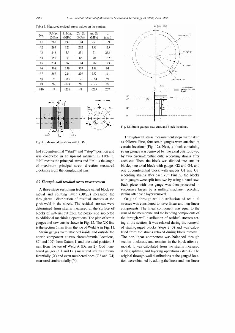
Table 3 summarizes measurement results: residual stresses on the outer surface (1-7) were tensile; axial stresses on the inner surface were compressive; and circumferential stresses were partly compressive and partly tensile. Maximum circumferential stress was found at #6, and the DMW region and maximum axial stress at #7, between the SA508 nozzle and the Alloy 182 buttered layer. Gauges #1-3 and #8-10 showed different values although they are located at the same axial positions (5 mm from Datum 2). Weld
2952 K.-S. Lee et al. / Journal of Mechanical Science and Technology 23 (2009) 2948~2955
Table 3. Measured residual stress values on the surface.
No. P.Max. (MPa)
P. Min.(MPa)
Cir. St (MPa)
Ax. St.(MPa)
α (deg.)
#1 260 192 194 258 189
#2 294 121 262 153 115
#3 248 55 231 71 253
#4 150 5 86 70 132
#5 234 36 174 96 123
#6 308 159 307 159 94
#7 367 224 239 352 161
#8 9 -186 7 -184 95
#9 97 -129 92 -125 98
#10 -7 -236 -8 -235 267
Fig. 11. Measured locations with HDM.
had circumferential ‘“start”’ and ‘“stop’” position and was conducted in an upward manner. In Table 3, ‘“P’” means the principal stress and ‘“α”’ is the angle of maximum principal stress direction measured clockwise from the longitudinal axis.
4.2 Through-wall residual stress measurement
A three-stage sectioning technique called block re-moval and splitting layer (BRSL) measured the through-wall distribution of residual stresses at the girth weld in the nozzle. The residual stresses were determined from strains measured at the surface of blocks of material cut from the nozzle and subjected to additional machining operations. The plan of strain gauges and saw cuts is shown in Fig. 12. The XX line is the section 5 mm from the toe of Weld A in Fig. 11.
Strain gauges were attached inside and outside the nozzle component at two circumferential locations, 82˚ and 107˚ from Datum 1, and one axial position, 5 mm from the toe of Weld A (Datum 2). Odd num-bered gauges (G1 and G3) measured strains circum-ferentially (X) and even numbered ones (G2 and G4) measured strains axially (Y) .
Fig. 12. Strain gauges, saw cuts, and block locations.
Through-wall stress measurement steps were taken
as follows. First, four strain gauges were attached at certain locations (Fig. 12). Next, a block containing strain gauges was removed by two axial cuts followed by two circumferential cuts, recording strains after each cut. Then, the block was divided into smaller blocks, one axial block with gauges G2 and G4, and one circumferential block with gauges G1 and G3, recording strains after each cut. Finally, the blocks with gauges were split into two by using a band saw. Each piece with one gauge was then processed in successive layers by a milling machine, recording strains after each layer removal.
Original through-wall distribution of residual stresses was considered to have linear and non-linear components. The linear component was equal to the sum of the membrane and the bending components of the through-wall distribution of residual stresses act-ing at the section. It was relaxed during the removal of strain-gauged blocks (steps 2, 3) and was calcu-lated from the strains relaxed during block removal. The non-linear component was balanced through section thickness, and remains in the block after re-moval. It was calculated from the strains measured during splitting and layering operations (step 4). The original through-wall distributions at the gauged loca-tion were obtained by adding the linear and non-linear
K.-S. Lee et al. / Journal of Mechanical Science and Technology 23 (2009) 2948~2955 2953
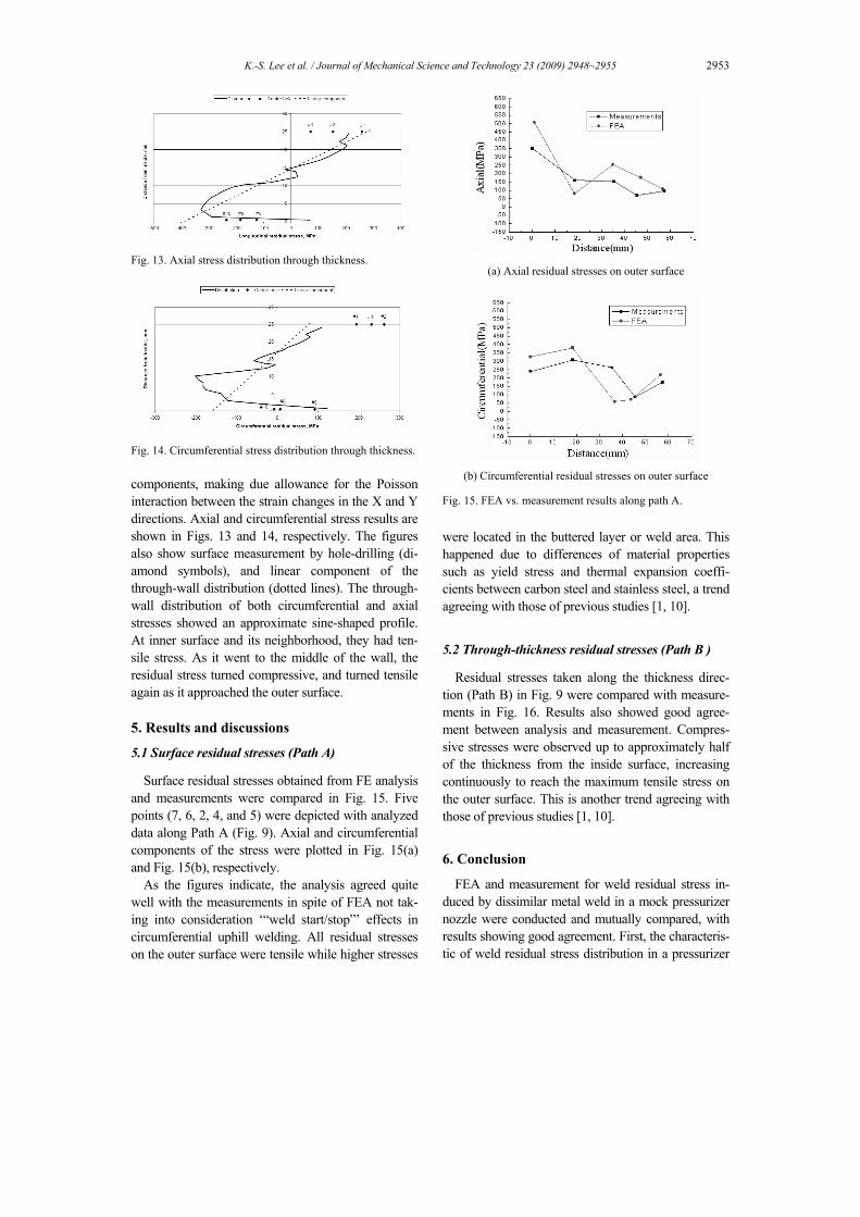
Fig. 13. Axial stress distribution through thickness.
Fig. 14. Circumferential stress distribution through thickness.
components, making due allowance for the Poisson interaction between the strain changes in the X and Y directions. Axial and circumferential stress results are shown in Figs. 13 and 14, respectively. The figures also show surface measurement by hole-drilling (di-amond symbols), and linear component of the through-wall distribution (dotted lines). The through-wall distribution of both circumferential and axial stresses showed an approximate sine-shaped profile. At inner surface and its neighborhood, they had ten-sile stress. As it went to the middle of the wall, the residual stress turned compressive, and turned tensile again as it approached the outer surface.
5. Results and discussions
5.1 Surface residual stresses (Path A)
Surface residual stresses obtained from FE analysis and measurements were compared in Fig. 15. Five points (7, 6, 2, 4, and 5) were depicted with analyzed data along Path A (Fig. 9). Axial and circumferential components of the stress were plotted in Fig. 15(a) and Fig. 15(b), respectively.
As the figures indicate, the analysis agreed quite well with the measurements in spite of FEA not tak-ing into consideration ‘“weld start/stop”’ effects in circumferential uphill welding. All residual stresses on the outer surface were tensile while higher stresses
(a) Axial residual stresses on outer surface
(b) Circumferential residual stresses on outer surface
Fig. 15. FEA vs. measurement results along path A.
were located in the buttered layer or weld area. This happened due to differences of material properties such as yield stress and thermal expansion coeffi-cients between carbon steel and stainless steel, a trend agreeing with those of previous studies [1, 10].
5.2 Through-thickness residual stresses (Path B )
Residual stresses taken along the thickness direc-tion (Path B) in Fig. 9 were compared with measure-ments in Fig. 16. Results also showed good agree-ment between analysis and measurement. Compres-sive stresses were observed up to approximately half of the thickness from the inside surface, increasing continuously to reach the maximum tensile stress on the outer surface. This is another trend agreeing with those of previous studies [1, 10].
6. Conclusion
FEA and measurement for weld residual stress in-duced by dissimilar metal weld in a mock pressurizer nozzle were conducted and mutually compared, with results showing good agreement. First, the characteris-tic of weld residual stress distribution in a pressurizer

2954 K.-S. Lee et al. / Journal of Mechanical Science and Technology 23 (2009) 2948~2955
(a) through-thickness axial stresses
(b) through-thickness circumferential stresses
Fig. 16. FEA vs. measurement results along path B.
nozzle became clear: higher tensile stresses occurred within or in the proximity of the buttering and the DMW region toward the outer surfaces, while com-pressive stress distribution showed the opposite. Stress magnitudes were found higher in DMW than in SMW. FEA methodology can be applied to assess the susceptibility of pressurizer nozzle to PWSCC. Sec-ond, simplified 2-D thermal and structural analysis can be applied to analyze the WRS of dissimilar metal butt weld in the nozzle. Third, hole-drilling and BRSL methods were quite useful in measuring the residual stress induced by welding on surface and through thickness, respectively.
Acknowledgment
This work was supported by the Research Program of the Department of Education and Technology (Mid/ Long-term Nuclear Power Research and Development Program), Republic of Korea. The project title was ‘“Development of Analysis Technology for Crack Management of Dissimilar Metal Weld”’, with serial number M207AE030001-08A0503-00110.
References
[1] T. K. Song, H. Y. Bae, Y. J. Kim., K. S. Lee, C. Y. Park, J. S. Yang, N. S. Huh, J. U. Kim, J. S. Park, M. S Song, S. K. Lee, J. S. Kim, S. C. Yu and Y. S. Chang, Assessment of round robin analyses results on welding residual stress prediction in a nuclear power plant nozzle, Transactions of the KSME A 33 (1) (2009) 72-81.
[2] C. Harrington, Advanced FEA evaluation of growth of postulated circumferential PWSCC flaws in pres-surizer nozzle dissimilar metal weld (MRP-216), EPRI, August 2007.
[3] K. Ahluwalia and C. King, Review of stress corro-sion cracking of alloy 182 and 82 in PWR primary water service (MRP-220), EPRI, October 2007.
[4] P. Dong and F. W. Brust, Welding residual stresses and effects on fracture in pressure vessel and piping components : A millennium review and beyond, ASME transactions : Journal of Pressure Vessel Technology, 122 (3) (2000) 329-338.
[5] E. F. Rybicki and R. B Stonesifer, Computation of Residual Stresses due to Multipass Welds in Piping Systems, Journal of Pressure Vessel Technology. (1979).
[6] F. I. Wamatsu, N. Yanagida and K. Miyazaki, Ef-fect of Weld Overlay Repair on Residual Stress and Crack Propagation in a Welding Pipe, PVP2007-26516.
[7] J. Zhang, P. Dong and F. W. Brust, A 3-D compos-ite shell element model for residual stress analysis of multi-pass welds, SMiRT 14 (1997).
[8] Y. Dong, J. K. Hong, C. L. Tsai and P. Dong, Finite Element Modeling of Residual Stresses in Austenitic Stainless Steel Pipe Girth Welds, Weld-ing Research Supplement (1997).
[9] R. Bradford, Through-thickness distribution of welding residual stresses in austenitic steel cylindri-cal butt welds, proceedings of United Kingdom, (2000) 1373-1381.
[10] P. O’Regan, Welding residual and operating stresses in PWR alloy 182 butt weld (MRP-106), ERPI, (2004).
[11] K. S. Lee, T. R. Kim., J. H. Park, M. W. Kim and S. Y. Cho, 3-D Characteristics of the Residual Stress in the Plate Butt Weld between SA 508 and F316L SS, KSME A 33 (4) (2009) 401-409.
[12] K. S. Lee, C. Y. Park, H. D. Kim, J. S. Kim and J. H. Park, Preliminary Evaluation of Primary Water Stress Corrosion Cracking Initiation Potential on
K.-S. Lee et al. / Journal of Mechanical Science and Technology 23 (2009) 2948~2955 2955
Small Penetration Nozzle Welds by Residual Stress Analysis, Journal of KPVP(3) (2007) 101-108.
[13] T. K. Song, H. Y. Bae, Y. J. Kim, K. S. Lee and C. Y. Park, Sensitivity Analysis of Finite Element Me-thod for Estimating Residual Stress of Dissimilar Metal Multi-Pass Weldment in Nuclear Power Plant, Transactions of the KSME A 32 (9) (2008) 770-781.
[14] T. K. Song, H. Y. Bae, Y. B. Chun, C. Y. Oh, Y. J. Kim, K. S Lee and C. Y. Park, Effect of Preemptive Weld Overlay on Residual Stress Mitigation for Dissimilar Metal Weld of Nuclear Power Plant Pressurizer, Transactions of the KSME A 32 (10) (2008) 873-881.
[15] T. K. Song, H. Y. Bae, Y. B Chun, C. Y. Oh, Y. J. Kim, K. S. Lee and C. Y. Park, Estimation of Re-sidual Stress Distribution for Pressurizer Nozzle of Kori Nuclear Power Plant Considering Safe End, Transactions of the KSME A 32 (8) (2008) 668-677.
[16] H. Y. Lee, J. B. Kim, J. H. Lee and K. M. Nikbin, Comprehensive Residual Stress Distributions in a Range of Plate and Pipe Components, Journal of Mechanical Science and Technology 20 (3) (2006) 335-344.
[17] J. U. Park and H. W. Lee, Effects of Initial Condi-tion of Steel Plate on Welding Deformation and Re-sidual Stress due to Welding, Journal of Mechanical Science and Technology 21 (3) (2007) 426-435.
[18] C. H. Jang, J. S. Kim and T. E. Jin, Mechanical Properties Evaluation in Inconel 82/182 Dissimilar Metal Welds, The Proceedings of SMiRT 19 (2007).
[19] C. H. Jang, J. S. Kim and T. E. Jin, Spatial Varia-tion of Mechanical Properties in Alloy 82/182 Dis-similar Metal Welds, The Proceedings of 6th Int. Workshop on Integrity of Nuclear Components (2006).
[20] J. S. Park and H. C. Song, K. S. Yoon and T. S. Choi, The Analysis of Dissimilar Metal Weld Joint for Fracture Mechanics Evaluations, SMiRT 18 (2005).
[21] J. S. Kim and T. E. Jin, Development of Engineer-ing Formula for Welding Residual Stress Distribu-tions of Dissimilar Welds on Nozzle in Nuclear Component, PVP2007-26729.
[22] T. K. Song, Y. J. Kim, K. S. Lee, C. Y. Park, J. S. Kim and J. W. Kim, Effect of Constraint and Inter-nal Medium on Residual Stress under Overlay Welding for Dissimilar Metal Welding, Proceed-ings of the KSME Fall Annual Meeting (2007).
[23] T. K. Song, H. Y. Bae, Y. J. Kim, K. S. Lee and C. Y. Park, A Study on the Residual Stress Relieving for Dissimilar Metal Weld under Weld, Proceedings of the KWJS Fall Annual Meeting (2007).
[24] Standard test method for determining residual stresses by the hole-drilling strain gage method, ASTM E837-01 (2001).
[25] R. H. Leggatt and S. J. Hurworth, BRSL-PC User Guide V 1.0. TWI (1991).
Kyoung-soo Lee received his B.S. degree in Mechanical Engin-eering from Bukyeong University, Korea, in 1989. He then received his M.S. degree in Mechanical Engineering from Hanyang Uni-versity, Korea, in 1999. Mr. Lee is currently a principal researcher at
the Korea Electric Power Research Institute in Daejeon, Korea. His research interests include analysis and meas-urement of residual stress, structural integrity of piping and vessel, and life assessment of nuclear power plant.