finishing of sls-parts for rapid … · finishing of sls-parts for rapid ... several suitable...
TRANSCRIPT

FINISHING OF SLS-PARTS FOR RAPID MANUFACTURING (RM) – A COMPREHENSIVE APPROACH –
M. Schmid*, C. Simon* and G.N. Levy*
*INSPIRE, irpd – Institute for Rapid Product Development, Lerchenfeldstr. 5,
CH-9000 St. Gallen, Switzerland
Abstract
Plastic parts are often coated to fulfill the desired functional requirements during product life. This may be for decorative purposes only, but also for functions such as improved tribology, wear and humidity resistance, UV- and light stability, hygienic and biofilm resistance. Moving SLS towards Rapid Manufacturing (RM) and making those parts competitive with parts produced by other techniques (e.g. injection molding) implies the adoption of a new quality of part finishing and coating strategy for SLS. This paper provides a survey of current finishing methods used for RM-SLS parts in our institute and highlights the manually-driven process steps. The need for, and first trials with, a more automated finishing process (e.g. vibratory grinding) are discussed, as is the need for innovative supporting software tools.
Introduction
Over the last two decades more than 30 different layer manufacturing (LM) technologies or “additive processing technologies” based on different technological principles have been developed. The most promising technologies have been engineered to a higher level and are now used for the production of prototypes, parts or models in a great number of applications [1-3]. LM technologies are divided into rapid prototyping (RP) and rapid manufacturing (RM) technologies, depending on the end use. RP involves the production of prototypes, visual design aids and test parts, while RM involves the production of actual production parts (end products).
At present, the market for RM applications is experiencing rapid growth [4], but suffers from certain drawbacks that hinder greater acceptance in the industry. Apart from the lack of several suitable polymeric materials for layer wise production [5], In general, the surface quality of SLS parts is relatively poor for various reasons [6]. Especially when SLS parts are compared with plastic parts produced with “classical” injection molding (IM) technology, there is an obvious difference in surface quality, as IM uses pressure and polished tools. Since, in our modern world, most plastic parts are coated for various reasons, RM has to take account of this market reality and develop strategies in order to remain competitive. Otherwise, the great advantage of SLS of increased complexity is obsolete due to inferior surface quality. This means that RM has to develop some basic methods for improving surface roughness in particular. This cannot be a manually-driven process as in RP (e.g. priming and polishing with abrasive papers), as a lot of parts must achieve the same quality that has to be guaranteed to the customer in advance. Previously described laser-based finishing approaches [8, 9] are also unusable due to the higher part numbers. One promising method that may satisfy this requirement for reproducible surface refining is vibratory grinding. Furthermore, functional coatings for SLS parts must be systematically evaluated in future, and their effectiveness for certain applications must also be demonstrated to customers in advance in order to fulfill the required specifications defined for
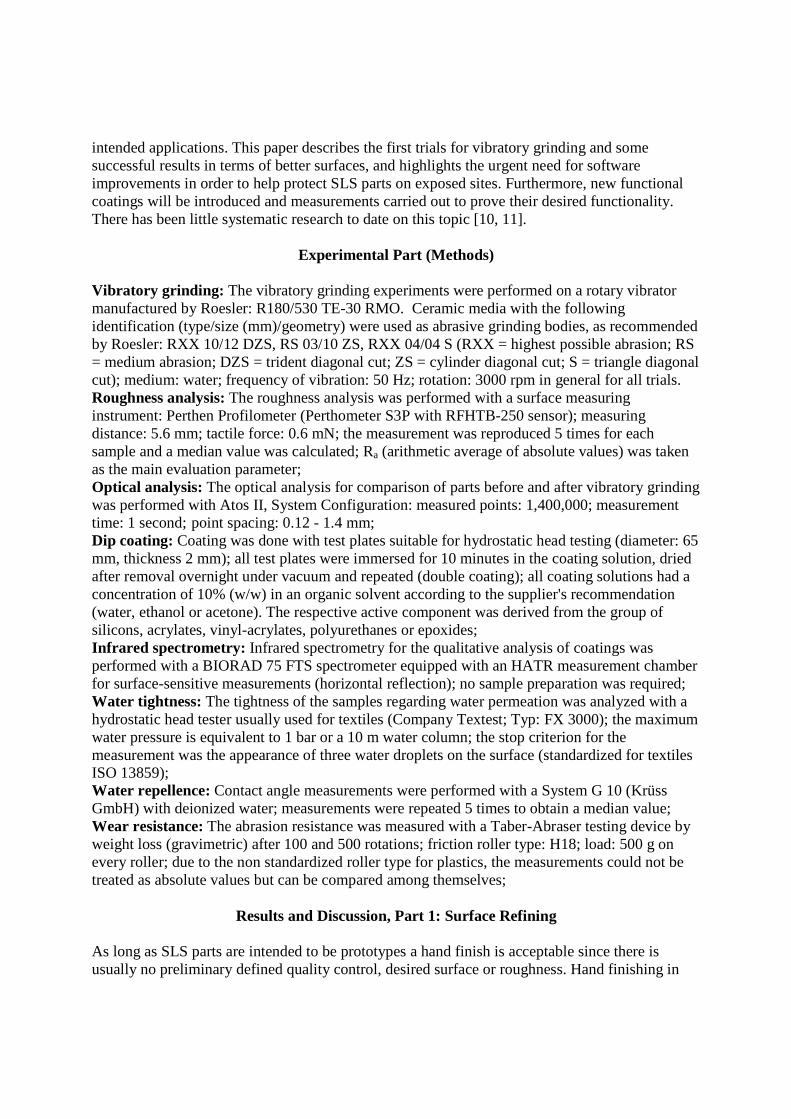
intended applications. This paper describes the first trials for vibratory grinding and some successful results in terms of better surfaces, and highlights the urgent need for software improvements in order to help protect SLS parts on exposed sites. Furthermore, new functional coatings will be introduced and measurements carried out to prove their desired functionality. There has been little systematic research to date on this topic [10, 11].
Experimental Part (Methods)
Vibratory grinding: The vibratory grinding experiments were performed on a rotary vibrator manufactured by Roesler: R180/530 TE-30 RMO. Ceramic media with the following identification (type/size (mm)/geometry) were used as abrasive grinding bodies, as recommended by Roesler: RXX 10/12 DZS, RS 03/10 ZS, RXX 04/04 S (RXX = highest possible abrasion; RS = medium abrasion; DZS = trident diagonal cut; ZS = cylinder diagonal cut; S = triangle diagonal cut); medium: water; frequency of vibration: 50 Hz; rotation: 3000 rpm in general for all trials. Roughness analysis: The roughness analysis was performed with a surface measuring instrument: Perthen Profilometer (Perthometer S3P with RFHTB-250 sensor); measuring distance: 5.6 mm; tactile force: 0.6 mN; the measurement was reproduced 5 times for each sample and a median value was calculated; Ra (arithmetic average of absolute values) was taken as the main evaluation parameter; Optical analysis: The optical analysis for comparison of parts before and after vibratory grinding was performed with Atos II, System Configuration: measured points: 1,400,000; measurement time: 1 second; point spacing: 0.12 - 1.4 mm; Dip coating: Coating was done with test plates suitable for hydrostatic head testing (diameter: 65 mm, thickness 2 mm); all test plates were immersed for 10 minutes in the coating solution, dried after removal overnight under vacuum and repeated (double coating); all coating solutions had a concentration of 10% (w/w) in an organic solvent according to the supplier's recommendation (water, ethanol or acetone). The respective active component was derived from the group of silicons, acrylates, vinyl-acrylates, polyurethanes or epoxides; Infrared spectrometry: Infrared spectrometry for the qualitative analysis of coatings was performed with a BIORAD 75 FTS spectrometer equipped with an HATR measurement chamber for surface-sensitive measurements (horizontal reflection); no sample preparation was required; Water tightness: The tightness of the samples regarding water permeation was analyzed with a hydrostatic head tester usually used for textiles (Company Textest; Typ: FX 3000); the maximum water pressure is equivalent to 1 bar or a 10 m water column; the stop criterion for the measurement was the appearance of three water droplets on the surface (standardized for textiles ISO 13859); Water repellence: Contact angle measurements were performed with a System G 10 (Krüss GmbH) with deionized water; measurements were repeated 5 times to obtain a median value; Wear resistance: The abrasion resistance was measured with a Taber-Abraser testing device by weight loss (gravimetric) after 100 and 500 rotations; friction roller type: H18; load: 500 g on every roller; due to the non standardized roller type for plastics, the measurements could not be treated as absolute values but can be compared among themselves;
Results and Discussion, Part 1: Surface Refining
As long as SLS parts are intended to be prototypes a hand finish is acceptable since there is usually no preliminary defined quality control, desired surface or roughness. Hand finishing in

this case involves a process used in many other connections (e.g. car repair) and consists mainly of three steps: application of a primer, polishing of surfaces and cosmetic spraying. Figure 1 shows the steps required, taking the example of a part (industry cover) produced in our factory. It is obvious that this process is - especially for the polishing step (red circle) - labour-intensive and requires specialized staff with certain skills (e.g. car body painter). Furthermore, the process is time-consuming and expensive. Figure 1: Composition of the process steps of surface refining with manual polishing; To overcome the drawbacks of the manual process we investigated, in collaboration with the company Roesler, the possibility of vibratory grinding for SLS parts and the corresponding effects. Please note that vibratory grinding is an entirely empirical process and can be validated only by experiment. Several test parts with a variety of selected geometries (planar surfaces, parts with edges and curving geometries) were chosen in order to obtain comprehensive information on achievable surface quality. The main factors influencing the results would be expected to be the ceramic media (abrasion body), the rotation speed and the time of exposure. Figure 2 gives an overview of the selected abrasion bodies. As regards the nomenclature of Roesler, RXX media are those with the highest abrasion performance available. RS media produce medium abrasion. The geometrical size of the media was selected to match the size of the SLS parts. Figure 2: Assembly of the ceramic media employed for the vibratory grinding tests
Primer Polish Spray
polishing by abrasivespriming traditional look
varnishable
Primer Polish Spray
polishing by abrasivespriming traditional look
varnishable
RXX 10/12 DZS RS 03/10 ZS RXX 04/04 SRXX 10/12 DZS RS 03/10 ZS RXX 04/04 S
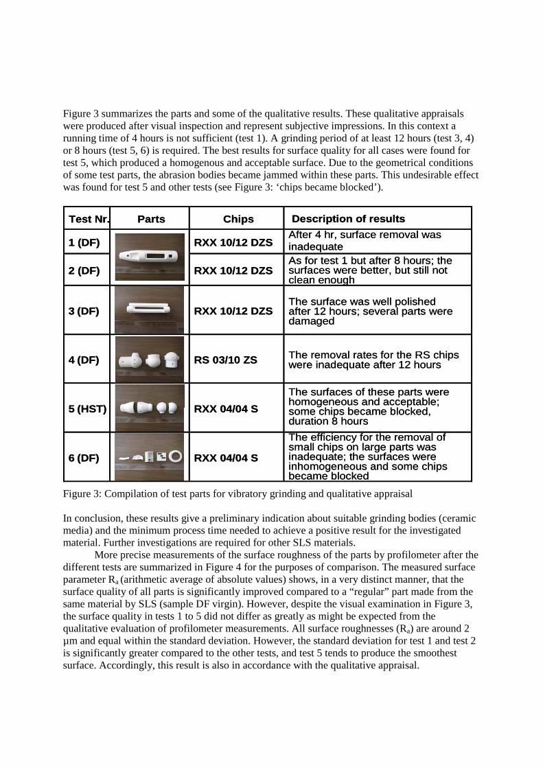
Figure 3 summarizes the parts and some of the qualitative results. These qualitative appraisals were produced after visual inspection and represent subjective impressions. In this context a running time of 4 hours is not sufficient (test 1). A grinding period of at least 12 hours (test 3, 4) or 8 hours (test 5, 6) is required. The best results for surface quality for all cases were found for test 5, which produced a homogenous and acceptable surface. Due to the geometrical conditions of some test parts, the abrasion bodies became jammed within these parts. This undesirable effect was found for test 5 and other tests (see Figure 3: ‘chips became blocked’). Figure 3: Compilation of test parts for vibratory grinding and qualitative appraisal In conclusion, these results give a preliminary indication about suitable grinding bodies (ceramic media) and the minimum process time needed to achieve a positive result for the investigated material. Further investigations are required for other SLS materials.
More precise measurements of the surface roughness of the parts by profilometer after the different tests are summarized in Figure 4 for the purposes of comparison. The measured surface parameter Ra (arithmetic average of absolute values) shows, in a very distinct manner, that the surface quality of all parts is significantly improved compared to a “regular” part made from the same material by SLS (sample DF virgin). However, despite the visual examination in Figure 3, the surface quality in tests 1 to 5 did not differ as greatly as might be expected from the qualitative evaluation of profilometer measurements. All surface roughnesses (Ra) are around 2 µm and equal within the standard deviation. However, the standard deviation for test 1 and test 2 is significantly greater compared to the other tests, and test 5 tends to produce the smoothest surface. Accordingly, this result is also in accordance with the qualitative appraisal.
Test Nr. Parts Chips Description of results
1 (DF) RXX 10/12 DZS
2 (DF) RXX 10/12 DZS
3 (DF) RXX 10/12 DZS
4 (DF) RS 03/10 ZS
5 (HST) RXX 04/04 S
6 (DF) RXX 04/04 S
After 4 hr, surface removal was inadequateAs for test 1 but after 8 hours; thesurfaces were better, but still notclean enough
The surface was well polishedafter 12 hours; several parts weredamaged
The removal rates for the RS chipswere inadequate after 12 hours
The surfaces of these parts werehomogeneous and acceptable;some chips became blocked,duration 8 hours
The efficiency for the removal ofsmall chips on large parts wasinadequate; the surfaces wereinhomogeneous and some chipsbecame blocked

Figure 4: Surface roughness (Ra) before and after vibratory grinding (DF virgin = untreated part) In addition to this qualitative and profilometer analysis, a space-resolved optical analysis (white light scanner with grid projection) was performed after vibratory grinding to obtain information about the material layer thickness abrasion. The result is a variance comparison between the SLS sintered part and the same part after vibratory processing. Figure 5 shows two parts that were analyzed by this technique. The colors represent the abrasion rate at different points. Blue represents no, or minimal, abrasion, while red indicates maximum abrasion loss of up to 250 µm. We can estimate a typical abrasion profile < 0.1 mm, but the maximum may even exceed 0.3 mm (indicating part damage). Figure 5: Optical analysis of parts after vibratory grinding and typical profile
Part 1
Part 2
Part 1
Part 2
0.0
2.0
4.0
6.0
8.0
10.0
12.0
14.0
DF virgin test 1 test 2 test 3 test 4 test 5
Ra

It is readily apparent that the results are as expected. Flat surfaces (Part 1) exhibit a very homogenous appearance with the desired optimized surface. As the edges are curved no dramatic weight loss is detected here either. A different result can be seen for Part 2 in Figure 5. The edges are severely damaged (red regions = abrasion loss of more than 250 µm).
This means that further basic research is required here. The main targeted research approach at the moment therefore focuses on the development of new software capable of detecting problematic regions in part geometry semi-automatically, so that these can then be covered with protecting aids. These auxiliary constructions must be arranged in such a way that they can easily be removed after processing. Further work should focus on a family-dependent media definition (abrasion media), optimized process parameters and suitable quality control after vibratory grinding.
Results and Discussion, Part 2: Functional Coating
In addition to the surface optimization (reduction of surface roughness (see Part1)), further enhancement is also needed for the application of functional coatings for RM in order to improve the parts for desired applications. This can be e.g. improved water tightness, humidity resistance, wear advancement, UV- and light stability, biofilm resistance, etc. Furthermore, a functional coating can sometimes help to compensate for the lack of feasible material grades for SLS. For this reason a dip coating (DC) process was established in order to facilitate the application of different coatings. Figure 6 illustrates the dip coating procedure. Basically, a DC solution is provided by dispersing an active chemical component with the desired functionality in an organic solvent or water. The part is then simply immersed in and removed from this solution. The great advantage of DC is the acceptance of any complexity of part geometry and the cheap and simple approach. Furthermore, the thickness of the layer can be controlled to a certain extent by modifying the concentration of active component in the solution, dwell time or removal action. Disadvantages of DC include the large amount of solution required for the complete immersion of larger parts and, in some cases, limited stability of the coating chemicals dissolved in the DC solution. Figure 6: Functional layers applied by the dip coating (DC) process
Immersion Dwell time Withdrawal
dip coating process
Immersion Dwell time Withdrawal
dip coating process

Various chemicals recommended by distributors for this purpose were utilized for the test that was basically designed to improve the water tightness of SLS parts. These chemicals belong to the group of silicones, acrylates, vinyl-acrylates, polyurethanes, etc. and were applied by DC to a disk specimen with a diameter of 60 mm and a thickness of 2 mm. The presence of a coating layer on the specimen was checked qualitatively by surface sensitive infrared spectrometry (HATR-IR). A hydrostatic water column tester (Textest FX 3000) was used for measuring water tightness. This measuring equipment is usually used for measuring the effectiveness of water-tight textiles, but was also found to be suitable for the assessment of coatings on SLS parts. For the test the coated SLS disks were sealed over the water bath of the FX 3000, and the pressure in the water was then increased linearly. As defined in textile standards (e.g. DIN 53886) the test is concluded when 3 droplets of water are visible on the dry side of the specimen. Figure 7 summarizes the results of the water tightness test for all applied coatings after a first and a second DC procedure. The water pressure [mbar] measured when three droplets are visible is noted. Figure 7: Results of water tightness measurements of different coatings on the SLS disk specimen in comparison with uncoated PA12 (Duraform) The following conclusions can be drawn from this figure. Certain coating chemicals improve the water tightness of PA12 (uncoated Duraform) as desired, whereas others even reduced water tightness. Polyurethane (PU) seems to be an unsuitable coating for water tightness purposes, although PU is very often used in practice. Silicones and vinyl-acrylates showed the desired positive effect of improving water head pressure to PA12. Whereas silicones need just one DC step and are not significantly improved by a second cycle, acrylic polymer seals need two or,
0
50
100
PA12 1 2 11 16 23 24 3 27 28 32 33 5 7 21 29 25 10 22 12 13 6 15 31 4 18 19 26 30
(material code numbers)
wate
r pre
ssure
[mba
r]
one time DCtwo times DC
Silicone Polyurethane Vinyl-AcrylpolymersDivers
> 1000 > 1000w
ate
r adso
rbed im
media
tely
wate
r adso
rbed im
media
tely

most likely, even more DC runs. Two coatings, in particular, are outstanding at both ends of the scale. Numbers 11 (silicon) and 15 (vinyl-acrylate) shows phenomenal water tightness in both cases for the second coating, until the maximum measuring range of the equipment is reached. The other end of the scale is represented by coatings 25 and 26. In these cases, the water droplets appeared on the surface immediately after the specimen was sealed. This behavior could even be beneficial if a high water absorbing material is desired for a certain application.
Another interesting aspect in this connection is the change in surface energy or hydrophobicity of a specimen with the different coatings. This effect is analyzed by contact angle measurements. The results of these measurements are summarized in Figure 8. If the contact angle is below 90° the surface is classified as hydrophilic, which is the case for almost all polyurethane and acryl polymer coatings. Silicones have a low affinity (surface energy) for water droplets and thus produce predominantly hydrophobic surfaces. A super-hydrophobic surface was achieved for coating number 16 (lotus effect). . Figure 8: Contact angle measurements on the different surfaces after coating Although it did not form the focus of this investigation of water tightness improvement, we also analyzed the friction behavior of some of the coatings with the Taber abrasion tester. Figure 9 clearly shows that some selected coatings also improve the wear behavior of PA 12 (Duraform = DF). Especially coating 16, which exhibited the highest hydrophobicity, also shows significantly reduced abrasion. Further research regarding this topic will be necessary and is already anticipated in our group.
0
90
180
PA12 1 2 11 16 23 24 3 27 28 32 33 5 7 21 29 25 10 22 12 13 6 15 31 4 18 19 26 30
(material code numbers)
one time DC
two times DC
Silicone Polyurethane Vinyl-Acrylpolymers Divers
hydrophilic
hydrophopic
superhydrophopic
wat
er s
prea
ded
imm
edia
tely
wat
er s
prea
ded
imm
edia
tely

Figure 9: Abrasion behavior of different coatings compared to virgin PA 12;
Conclusion and Outlook
This paper shows that vibratory grinding is a promising approach for refining SLS parts from the standpoint of surfaces. In progressing from RP to RM this is an essential step in guaranteeing the surface qualities and process reliability required by customers. Suitable ceramic bodies were investigated and process times were determined. In the optical variance analysis we demonstrated that parts without complex structures are readily amenable to vibratory grinding (removal < 0.1 mm). Further research is necessary to improve the protection of the more critical parts for the process in its sensitive regions, and process parameters for vibratory grinding also need to be refined. The application of functional layers to SLS parts by dip coating was shown to be a simple and fairly powerful tool in this work. Chemical coatings that improve the water tightness of PA12 parts were successfully investigated. Furthermore, the change in surface energy and abrasion resistance due to the surface coatings was also demonstrated. Moreover, the method is also to be used in future for investigations on UV-protecting coatings and flame retardancy. Additionally, functional coatings may sometimes help to compensate for the lack of material grades that are suitable for SLS.
Acknowledgements
I am grateful to the whole laboratory staff of our Institute who supported this work, especially Martin Eichenberger who applied all the coatings and carried out almost all the analytical work.
17
.4
8.7 11
.9
14
.9
12
.7
13
.0
17
.3
13
.7
7.7
8.7
3.1
14
.2
0.0
5.0
10.0
15.0
20.0
25.0
30.0
35.0
40.0
45.0
DF 11 13 15 16 33sample codes
wei
gh
t lo
ss [m
g]
100-500 ro tations
0-100 ro tations

Literature
1 Kruth J.-P., Levy G. et al., Consolidation phenomena in laser and powder-bed based layered manufacturing CIRP Annals - Manufacturing Technology, 56(2), 2007, 730-759
2 Levy G., Schindel R. et al., Rapid Manufacturing and Rapid Tooling with Layer Manufacturing (LM) Technologies, State of the Art and Future Perspectives, CIRP Annals - Manufacturing Technology, 52(2), 2003, 589-609
3 Wendel B., Rietzel D. et al. Additive Processing of polymers, Macromol Mater. Eng. 293, 2008, 799-809,
4 Wohlers Report 2009, Chapter 2: Industry growth, Wohlers Associates Inc, Fort Collins, Colorado 80525 USA
5 Wendel B., Rietzel D., Kühnlein F., et al., Additive Processing of Polymers, Macromal. Mater. Eng. 2008, 293,
6 Kruth J.-P., Levy G., Schindel R., et al., Consolidation of Polymer Powders by Selective Laser Sintering, PMI 2008, International Conference, 17 - 19 September 2008, Ghent, Belgium
8 Shi, D; Gibson, I; Improving surface quality of selective laser sintered rapid prototype parts using robotic finishing, The Institution of Mechanical Engin. Part B-J. Engin. Manufacture, 2000, 214(3), 197-203
9 Lamikiz, A; Sanchez, JA; de Lacalle, LNL, et al. Laser polishing of parts built up by selective laser sintering Int. J. Machine Tools & Manufacture 2007, 47, 2040-2050
10 Bacchewar P.B.; Singhal S.K., et al., Statistical modelling and optimization of surface roughness in the selective laser sintering process, The Institution of Mechanical Engin. Part B, J. Engin. Manufacture, 2007, 221(1), 35-52
11 Takacs, J., Toth L., Franek F., et al. Friction and wear measurements of laser-sintered and coated parts Conference Information: 14th International Conference on Wear of Materials, 2003 Washington D.C., Source: Wear, 2004, 256(11-12), 1228-1231