finisher, sorter, deliverytray finisher-v1 · pdf fileintroduction the following rules apply...
TRANSCRIPT

Aug 24 2007
Service Manual
Finisher, Sorter, DeliveryTrayFinisher-V1


ApplicationThis manual has been issued by Canon Inc. for qualified persons to learn technical theory, installation, maintenance, and repair
of products. This manual covers all localities where the products are sold. For this reason, there may be information in this
manual that does not apply to your locality.
CorrectionsThis manual may contain technical inaccuracies or typographical errors due to improvements or changes in products. When
changes occur in applicable products or in the contents of this manual, Canon will release technical information as the need
arises. In the event of major changes in the contents of this manual over a long or short period, Canon will issue a new edition
of this manual.
The following paragraph does not apply to any countries where such provisions are inconsistent with local law.
TrademarksThe product names and company names used in this manual are the registered trademarks of the individual companies.
CopyrightThis manual is copyrighted with all rights reserved. Under the copyright laws, this manual may not be copied, reproduced or
translated into another language, in whole or in part, without the written consent of Canon Inc.
COPYRIGHT © 2001 CANON INC.Printed in Japan
CautionUse of this manual should be strictly supervised to avoid disclosure of confidential information.

Introduction
Symbols UsedThis documentation uses the following symbols to indicate special information:
Symbol Description
Indicates an item of a non-specific nature, possibly classified as Note, Caution, or Warning.
Indicates an item requiring care to avoid electric shocks.
Indicates an item requiring care to avoid combustion (fire).
Indicates an item prohibiting disassembly to avoid electric shocks or problems.
Indicates an item requiring disconnection of the power plug from the electric outlet.
Indicates an item intended to provide notes assisting the understanding of the topic in question.
Indicates an item of reference assisting the understanding of the topic in question.
Provides a description of a service mode.
Provides a description of the nature of an error indication.
Memo
REF.

Introduction
The following rules apply throughout this Service Manual:1. Each chapter contains sections explaining the purpose of specific functions and the relationship between electrical and mechanical systems with refer-
ence to the timing of operation.In the diagrams, represents the path of mechanical drive; where a signal name accompanies the symbol , the arrow indicates thedirection of the electric signal.The expression "turn on the power" means flipping on the power switch, closing the front door, and closing the delivery unit door, which results insupplying the machine with power.
2. In the digital circuits, '1'is used to indicate that the voltage level of a given signal is "High", while '0' is used to indicate "Low".(The voltage value, how-ever, differs from circuit to circuit.) In addition, the asterisk (*) as in "DRMD*" indicates that the DRMD signal goes on when '0'.In practically all cases, the internal mechanisms of a microprocessor cannot be checked in the field. Therefore, the operations of the microprocessorsused in the machines are not discussed: they are explained in terms of from sensors to the input of the DC controller PCB and from the output of theDC controller PCB to the loads.
The descriptions in this Service Manual are subject to change without notice for product improvement or other purposes, and major changes will be com-municated in the form of Service Information bulletins.All service persons are expected to have a good understanding of the contents of this Service Manual and all relevant Service Information bulletins and beable to identify and isolate faults in the machine."


Contents
Contents
Chapter 1 Specifications
1.1 Product Specifications ................................................................................................................................1- 11.1.1 Specifications (finisher) ...........................................................................................................................................1- 1
1.2 Names of Parts ...........................................................................................................................................1- 41.2.1 External View...........................................................................................................................................................1- 41.2.2 Cross Section ..........................................................................................................................................................1- 5
Chapter 2 Installation
2.1 Making Pre-Checks ....................................................................................................................................2- 12.1.1 Checking the Contents ............................................................................................................................................2- 12.1.2 Order of Installing Accessories................................................................................................................................2- 22.1.3 Installation Space ....................................................................................................................................................2- 3
2.2 Unpacking and Checking the Components ................................................................................................2- 32.2.1 Unpacking................................................................................................................................................................2- 3
2.3 Installation Procedure.................................................................................................................................2- 62.3.1 Preparing the Finisher .............................................................................................................................................2- 62.3.2 Preparing the Host Machine ....................................................................................................................................2- 62.3.3 Connecting to the Host Machine .............................................................................................................................2- 72.3.4 Connecting to the High-Capacity Stacker................................................................................................................2- 82.3.5 Connecting to the Perfect Binder.............................................................................................................................2- 92.3.6 Connecting to the Professional Puncher ...............................................................................................................2- 112.3.7 After the Work........................................................................................................................................................2- 14
2.4 Making Adjustments .................................................................................................................................2- 152.4.1 Adjusting the Height .............................................................................................................................................. 2- 152.4.2 Adjusting the Tilt ....................................................................................................................................................2- 17
2.5 Attaching the Labels etc. ..........................................................................................................................2- 182.5.1 Attaching the Various Labels.................................................................................................................................2- 18
Chapter 3 Functions
3.1 Basic Construction......................................................................................................................................3- 13.1.1 Overview..................................................................................................................................................................3- 1
3.2 Electrical Control Unit .................................................................................................................................3- 13.2.1 Overview..................................................................................................................................................................3- 13.2.2 Finisher Controller PCB...........................................................................................................................................3- 1
3.3 Stacking Unit ..............................................................................................................................................3- 23.3.1 Overview..................................................................................................................................................................3- 23.3.2 Tray Ascent/Descent Control...................................................................................................................................3- 33.3.3 Auxiliary Tray Lift Control ........................................................................................................................................3- 43.3.4 Tray Paper Surface Detection .................................................................................................................................3- 4
3.4 Feeding Unit ...............................................................................................................................................3- 53.4.1 Overview..................................................................................................................................................................3- 53.4.2 Basic Sequence of Operations ................................................................................................................................3- 83.4.3 Horizontal Registration Detection ............................................................................................................................3- 83.4.4 Horizontal Registration Correction/Alignment Operation....................................................................................... 3- 103.4.5 Buffer Operation ....................................................................................................................................................3- 123.4.6 Switching Over the Paper Path .............................................................................................................................3- 13
3.5 Intermediate Process Tray Assembly .......................................................................................................3- 143.5.1 Overview................................................................................................................................................................3- 14

Contents
3.5.2 Basic Sequence of Operations ..............................................................................................................................3- 163.5.3 Stacking Operation ................................................................................................................................................3- 173.5.4 Alignment ...............................................................................................................................................................3- 193.5.5 Stapling Operation .................................................................................................................................................3- 203.5.6 Delivery Operation .................................................................................................................................................3- 21
3.6 Detecting Jams......................................................................................................................................... 3- 223.6.1 Jam Detection in the Finisher Assembly................................................................................................................3- 22
3.7 Power Supply ........................................................................................................................................... 3- 233.7.1 Overview................................................................................................................................................................3- 233.7.2 Protective Mechanism............................................................................................................................................3- 24
Chapter 4 Parts Replacement Procedure
4.1 Removing from the Host Machine .............................................................................................................. 4- 14.1.1 Finisher Assembly....................................................................................................................................................4- 1
4.1.1.1 Disconnecting from the Host Machine ..................................................................................................................................... 4- 14.2 External Covers .......................................................................................................................................... 4- 1
4.2.1 Rear Lower Cover....................................................................................................................................................4- 14.2.1.1 Removing the Low Rear Cover................................................................................................................................................ 4- 1
4.2.2 Rear Upper Cover....................................................................................................................................................4- 24.2.2.1 Removing the Upper Rear Cover (right) .................................................................................................................................. 4- 24.2.2.2 Before Removing the Upper Rear Cover (left)......................................................................................................................... 4- 24.2.2.3 Removing the Upper Rear Cover (left) .................................................................................................................................... 4- 2
4.2.3 Upper Cover Unit .....................................................................................................................................................4- 24.2.3.1 Before Removing the Upper Cover Unit .................................................................................................................................. 4- 24.2.3.2 Removing the Upper Cover Unit .............................................................................................................................................. 4- 2
4.2.4 Delivery Tray............................................................................................................................................................4- 34.2.4.1 Position of the Tray B at Power-On ......................................................................................................................................... 4- 3
4.2.5 Stack Wall (Upper)...................................................................................................................................................4- 34.2.5.1 Removing the Stacking Wall (upper) ....................................................................................................................................... 4- 3
4.2.6 Stack Wall (Lower)...................................................................................................................................................4- 34.2.6.1 Before Removing the Stacking Wall (lower) ............................................................................................................................ 4- 34.2.6.2 Removing the Stacking Wall (lower) ........................................................................................................................................ 4- 34.2.6.3 Mounting the Stacking Wall (lower) ......................................................................................................................................... 4- 4
4.2.7 Rear Middle Cover ...................................................................................................................................................4- 44.2.7.1 Removing the Middle Rear Cover............................................................................................................................................ 4- 4
4.2.8 Inside Cover (Upper)................................................................................................................................................4- 44.2.8.1 Before Removing the Inside Cover (upper) ............................................................................................................................. 4- 44.2.8.2 Removing the Inside Cover (upper) ......................................................................................................................................... 4- 4
4.2.9 Inside Cover (Lower)................................................................................................................................................4- 44.2.9.1 Removing the Inside Cover (lower).......................................................................................................................................... 4- 4
4.3 Drive System .............................................................................................................................................. 4- 54.3.1 Staple Unit ...............................................................................................................................................................4- 5
4.3.1.1 Before Removing the Stapler................................................................................................................................................... 4- 54.3.1.2 Removing the Stapler .............................................................................................................................................................. 4- 5
4.3.2 Front Alignment Motor .............................................................................................................................................4- 54.3.2.1 Before Removing the Alignment Motor (frontÅj ....................................................................................................................... 4- 54.3.2.2 Removing the Alignment Motor (front) ..................................................................................................................................... 4- 5
4.3.3 Rear Alignment Motor ..............................................................................................................................................4- 64.3.3.1 Before Removing the Alignment Motor (rear) ......................................................................................................................... 4- 64.3.3.2 Removing the Alignment Motor (rear)...................................................................................................................................... 4- 6
4.3.4 Tray Shift Motor .......................................................................................................................................................4- 74.3.4.1 Removing the Tray A/B Lift Motor............................................................................................................................................ 4- 7
4.3.5 Shift Motor................................................................................................................................................................4- 74.3.5.1 Before Removing the Shift Motor............................................................................................................................................. 4- 74.3.5.2 Removing the Shift Motor ........................................................................................................................................................ 4- 8
4.3.6 Belt Controller Unit.................................................................................................................................................4- 104.3.6.1 Before Removing the Belt Controller Unit .............................................................................................................................. 4- 10

Contents
4.3.6.2 Removing the Belt Controller Unit.......................................................................................................................................... 4- 104.4 Document Feeding System ......................................................................................................................4- 11
4.4.1 Stack Delivery Roller .............................................................................................................................................4- 114.4.1.1 Before Removing the Stack Delivery Upper Roller ................................................................................................................ 4- 114.4.1.2 Removing the Stack Delivery Upper Roller............................................................................................................................ 4- 11
4.4.2 Process Tray Assembly.........................................................................................................................................4- 124.4.2.1 Before Removing the Handling Tray Unit .............................................................................................................................. 4- 124.4.2.2 Removing the Handling Tray Unit .......................................................................................................................................... 4- 12
4.4.3 Process Tray .........................................................................................................................................................4- 134.4.3.1 Before Removing the Handling Tray (front/rear).................................................................................................................... 4- 134.4.3.2 Removing the Handling Tray (front)....................................................................................................................................... 4- 134.4.3.3 Removing the Handling Tray (rear)........................................................................................................................................ 4- 14
4.4.4 Feed Belt ............................................................................................................................................................... 4- 144.4.4.1 Before Removing the Transport Belt...................................................................................................................................... 4- 144.4.4.2 Removing the Transport Belt ................................................................................................................................................. 4- 14
4.4.5 Paddle Unit ............................................................................................................................................................4- 154.4.5.1 Before Removing the Paddle Unit.......................................................................................................................................... 4- 154.4.5.2 Removing the Paddle Unit ..................................................................................................................................................... 4- 15
4.4.6 Paddle ...................................................................................................................................................................4- 154.4.6.1 Before Removing the Paddle ................................................................................................................................................. 4- 154.4.6.2 Removing the Paddle............................................................................................................................................................. 4- 15
4.4.7 Tray Unit ................................................................................................................................................................4- 154.4.7.1 Before Removing the Tray A/B Unit....................................................................................................................................... 4- 154.4.7.2 Removing the Tray A/B Unit .................................................................................................................................................. 4- 154.4.7.3 Points to Note About the Tray A/B Cable............................................................................................................................... 4- 174.4.7.4 Points to Note When Handling the Stacking Wall Rail ........................................................................................................... 4- 17
4.5 Electrical System ......................................................................................................................................4- 174.5.1 Finisher Controller PCB.........................................................................................................................................4- 17
4.5.1.1 Finisher Controller PCB ......................................................................................................................................................... 4- 174.5.2 Static Charge Eliminator........................................................................................................................................4- 17
4.5.2.1 Removing the Stack Edging Roller Static Eliminator ............................................................................................................. 4- 174.5.2.2 Before Removing the Static Eliminator (upper delivery slot).................................................................................................. 4- 184.5.2.3 Removing the Stack Eliminator (upper delivery slot) ............................................................................................................. 4- 184.5.2.4 Before Removing the Stack Eliminator (inside delivery guide/inside delivery roller) ............................................................. 4- 184.5.2.5 Removing the Stack Eliminator (inside delivery guide).......................................................................................................... 4- 184.5.2.6 Removing the Static Eliminator (inside delivery roller)........................................................................................................... 4- 18
4.5.3 Horizontal Registration Sensor Unit ......................................................................................................................4- 184.5.3.1 Before Removing the Horizontal Registration Sensor Unit .................................................................................................... 4- 184.5.3.2 Removing the Horizontal Registration Sensor Unit................................................................................................................ 4- 18
Chapter 5 Maintenance
5.1 User Maintenance ......................................................................................................................................5- 15.1.1 User Maintenance Items (finisher)...........................................................................................................................5- 1
5.2 Maintenance and Inspection.......................................................................................................................5- 15.2.1 Periodically Replaced Parts.....................................................................................................................................5- 1
5.2.1.1 Periodically Replaced Parts in the Finisher ............................................................................................................................. 5- 15.2.1.2 Periodically Replaced Parts in the Saddle Finisher ................................................................................................................. 5- 1
5.2.2 Durables ..................................................................................................................................................................5- 25.2.2.1 Durables in the Finisher ........................................................................................................................................................... 5- 25.2.2.2 Durables in the Saddle Stitcher ............................................................................................................................................... 5- 2
5.2.3 Periodical Servicing .................................................................................................................................................5- 25.2.3.1 Scheduled Servicing for the Finisher ....................................................................................................................................... 5- 25.2.3.2 Scheduled Servicing for the Saddle Stitcher............................................................................................................................ 5- 2
5.3 Adjustment..................................................................................................................................................5- 35.3.1 Basic Adjustment.....................................................................................................................................................5- 3
5.3.1.1 Adjusting the Height................................................................................................................................................................. 5- 35.3.1.2 Adjusting the Tilt ...................................................................................................................................................................... 5- 45.3.1.3 Adjusting the Horizontal Registration/Angle............................................................................................................................. 5- 5

Contents
5.3.1.4 Adjusting the Horizontal Registration/Angle (if a paper folding unit has been installed).......................................................... 5- 75.3.1.5 Adjusting the Sensor Intensity ................................................................................................................................................. 5- 8
5.3.2 Adjustment at Time of Parts Replacement ............................................................................................................5- 105.3.2.1 Adjusting the Tray A/B Position ............................................................................................................................................. 5- 105.3.2.2 Adjusting the Angle of the Aligning Plate (orthogonal)........................................................................................................... 5- 105.3.2.3 Adjusting the Stapler Position ................................................................................................................................................ 5- 105.3.2.4 Adjusting the Speed of the Swing Guide ............................................................................................................................... 5- 115.3.2.5 Adjusting the Aligning Plate Width ......................................................................................................................................... 5- 115.3.2.6 Adjusting the Transport Belt Position..................................................................................................................................... 5- 135.3.2.7 Adjusting the Stapling Position (rear 1-point)......................................................................................................................... 5- 145.3.2.8 Adjusting the Stapling Position (front 1-point)........................................................................................................................ 5- 165.3.2.9 usting the Stapling Position (2-point) ..................................................................................................................................... 5- 175.3.2.10 Adjusting the Delivery of Stapled Stacks (lower delivery) .................................................................................................... 5- 195.3.2.11 Adjustment of EEPROM (IC107) on the Finisher Controller PCB After Replacement ......................................................... 5- 20
5.3.3 Other ......................................................................................................................................................................5- 225.3.3.1 Service Mode (by DIP switch)<Incerter> ............................................................................................................................... 5- 22
5.4 Troubleshooting........................................................................................................................................ 5- 235.4.1 Malfunction.............................................................................................................................................................5- 23
5.4.1.1 Malfunction/Faulty Detection.................................................................................................................................................. 5- 235.5 Outline of Electrical Components ............................................................................................................. 5- 26
5.5.1 Sensors (Finisher Unit) ..........................................................................................................................................5- 265.5.2 Microswitches (Finisher Unit).................................................................................................................................5- 295.5.3 Solenoids (Finisher Unit)........................................................................................................................................5- 305.5.4 Motors (Finisher Unit) ............................................................................................................................................5- 325.5.5 Fans (Finisher Unit) ...............................................................................................................................................5- 34
5.6 Variable Resistors (VR), Light-Emitting Diodes (LED), and Check Pins by PCB..................................... 5- 345.6.1 Overview................................................................................................................................................................5- 345.6.2 Finisher Controller PCB .........................................................................................................................................5- 35
5.7 Service Tools............................................................................................................................................ 5- 355.7.1 Solvents and Oils ...................................................................................................................................................5- 35
Chapter 6 Error Code
6.1 Overview .................................................................................................................................................... 6- 16.1.1 Overview..................................................................................................................................................................6- 1
6.2 Service Error Code..................................................................................................................................... 6- 16.2.1 Service Error Code for the Finisher .........................................................................................................................6- 1

Chapter 1 Specifications


Contents
Contents
1.1 Product Specifications....................................................................................................................................................1-11.1.1 Specifications (finisher) ............................................................................................................................................................... 1-1
1.2 Names of Parts ...............................................................................................................................................................1-41.2.1 External View .............................................................................................................................................................................. 1-41.2.2 Cross Section ............................................................................................................................................................................... 1-5


Chapter 1
1-1
1.1 Product Specifications
1.1.1 Specifications (finisher)0011-2153
T-1-1
1: The number of sheets refers to the result of conversion based on paper of 80g/m2
2: A sheet of paper may be grouped into the following:-large-size; A3,B4,279.4mmx432.8mm(11x17),LGL-small-size; A4,A5,B5,EXE,LTR,STMT,postcard,A4R,B5R,LTRR
T-1-2
Item Description Remarks
Stacking mechanism tray A/B by tray lift
Stacking orientation tray A face-down/face-up
tray B face-down
Stack size tray A A3,A4,A4R,A5R,B4,B5,B5R,Jpn postcard R,279.4mmx432.8mm(11x17),LGL,LTR,EXE,LTRR,STMTR,EXER
in feed direction, 148 to 432.8 mm; in cross-feed direction,100 to 297 mm
tray B A3,A4,A4R,B4,B5,B5R,279.4mmx432.8mm(11x17),LGL,LTR,EXE,LTRR,EXER in feed direction, 182 to 432.8 mm; in cross-feed direction, 182 to 297mm
Types of Paper Plain paper (64g/m2 to 90g/m2), Heavy paper (91 g/m2 to 200 g/m2), Recycled paper, Colored paper, Postcard, Label, Index paper, Tracing paper, 3-hole paper.
Number of trays 2
Mode type non-staple, staple
Number of sheets (Note 1) non-staple sort tray A: if small-/large-size, equivalent of 1000 sheets(147 mm in height) in multiple mode, the number of sheets are as follows:if small-size, equivalent of 3000 sheets (423 mm in height); if large-size, 1500 sheets (216 mm in height)
tray B: if small-size, equivalent of 2000 sheets (285mm in height),if large-size, equivalent of 1000 sheets(147 mm in height)
staple sort tray A: if small-/large-size, equivalent of 1000 sheets (147 mm in height), or 100 sets
tray B: if small-size, equivalent of 2000 sheets (285 mm in height), or 100 sets; if large-size, equivalent of 1000 sheets (147 mm in height), or 100 sets
Staple/non-staple mix (Note 1)
if small-size, equivalent of 200 sets (285 m in height), or 100 sets; if large-size, equivalent of 100 sheets(9147 mm in height), or 100 sets
applicable to tray B only
Folded sheet mix (Note 1) tray A: 10 folded sheets max. per set/20 folded sheets max. per job
tray B: 10 folded sheets max. per set/30 folded sheets max. per job
Stapling method stapling by rotating cam
Stapled stack if small-size, 100 sheets as converted with reference to paper of 80g/m2
if large-size, 50 sheets
Item Description Remarks
Staple accommodation in special staple cartridge (5000 staples)
Detection of staples yes an alert condition identified at 0 to 40 staples
Manual stapling no

Chapter 1
1-2
Stack size front 1-point
A3,A4,A4R,B4,B5,279.4mmx432.8mm(11x17),EXE,LGL,LTR,LTRR
rear 1-point
A3,A4,A4R,B4,B5,279.4mmx432.8mm(11x17),EXE,LGL,LTR,LTRR
2-point
A3,A4,A4R,B4,B5,279.4mmx432.8mm(11x17),EXE,LGL,LTR,LTRR
Paper detection yes
Control panel no
Display no
Dimensions W:800xD:786xH:1180mm
Weight 126 kg (approx.)
Power supply 100V,200-240V
Maximum power consumption 360 W or less
Item Description Remarks
Chapter 1
1-3
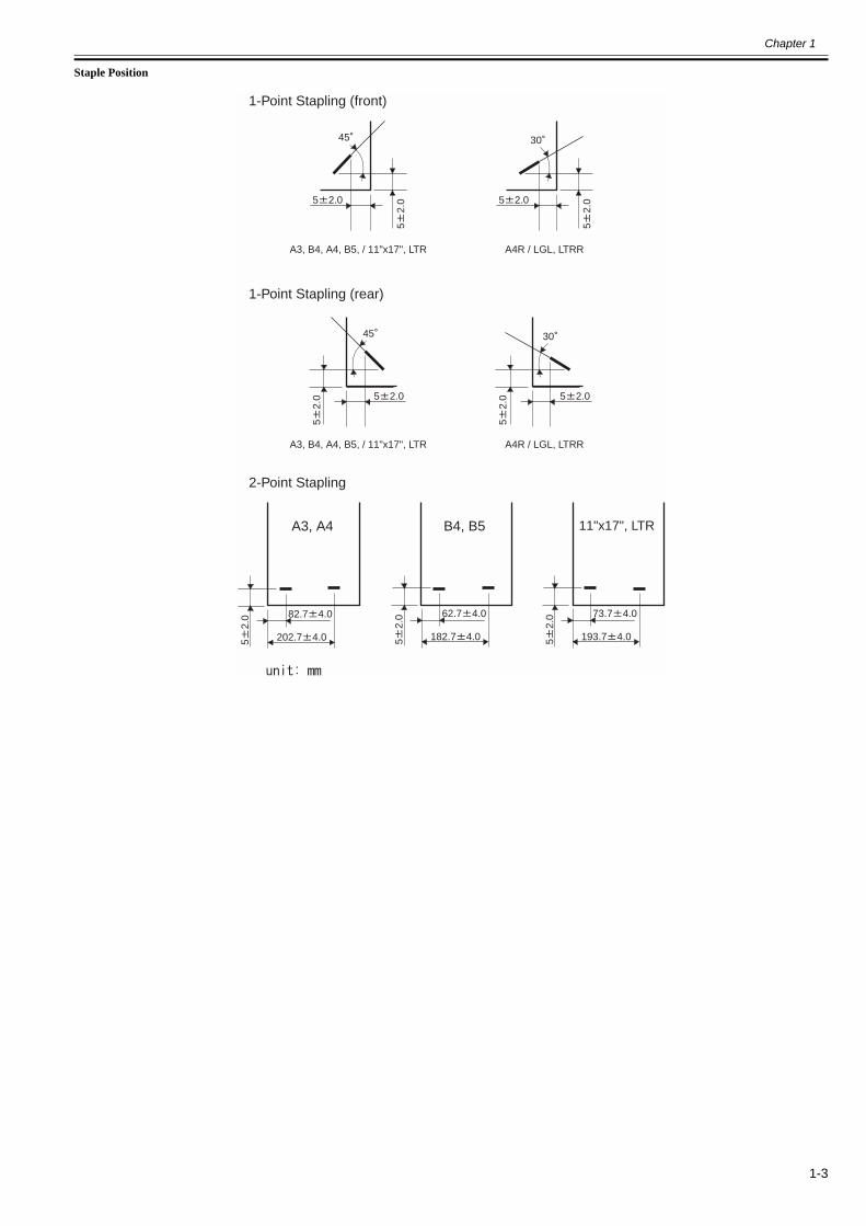
Staple Position
1-Point Stapling (front)
1-Point Stapling (rear)
2-Point Stapling
A3, A4 B4, B5
52.
0 73.7 4.0
193.7 4.052.
0 62.7 4.0
182.7 4.052.
0 82.7 4.0
202.7 4.0
52.
0
45
5 2.0
52.
0
30
5 2.05
2.0
45
A3, B4, A4, B5, / 11"x17", LTR
5 2.0
52.
0
30
A4R / LGL, LTRR
A3, B4, A4, B5, / 11"x17", LTR A4R / LGL, LTRR
5 2.0
11"x17", LTR

Chapter 1
1-4
1.2 Names of Parts
1.2.1 External View0011-1142
F-1-1
[1]Tray B [5]Upper cover
[2]Tray A [6]Inlet transport unit
[3]Top delivery outlet [7]Front cover
[4]Bottom delivery outlet
[1]
[2] [3]
[4]
[5]
[6]
[7]

Chapter 1
1-5
1.2.2 Cross Section0011-1170
F-1-2
[1]Transport belt [14]Assist roller 2
[2]Stack delivery roller [15]Shift roller 2
[3]Swing guide [16]Shift roller 1
[4]Paddle [17]Assist roller 1
[5]Tray B [18]Inlet transport roller
[6]Stack transport roller [19]Stapler
[7]Tray A
[8]Delivery roller
[9]Buffer roller 2
[10]Assist roller 3
[11]Buffer roller 3
[12]Transport roller
[13]Buffer roller 1
[1]
[2]
[3]
[4]
[5]
[7] [8] [9]
[6]
[10] [11] [12]
[13]
[14]
[15]
[16]
[17]
[18]
[19]


Chapter 2 Installation


Contents
Contents
2.1 Making Pre-Checks........................................................................................................................................................2-12.1.1 Checking the Contents ................................................................................................................................................................. 2-12.1.2 Order of Installing Accessories.................................................................................................................................................... 2-22.1.3 Installation Space ......................................................................................................................................................................... 2-3
2.2 Unpacking and Checking the Components ....................................................................................................................2-32.2.1 Unpacking .................................................................................................................................................................................... 2-3
2.3 Installation Procedure ....................................................................................................................................................2-62.3.1 Preparing the Finisher .................................................................................................................................................................. 2-62.3.2 Preparing the Host Machine......................................................................................................................................................... 2-62.3.3 Connecting to the Host Machine.................................................................................................................................................. 2-72.3.4 Connecting to the High-Capacity Stacker.................................................................................................................................... 2-82.3.5 Connecting to the Perfect Binder ................................................................................................................................................. 2-92.3.6 Connecting to the Professional Puncher .................................................................................................................................... 2-112.3.7 After the Work ........................................................................................................................................................................... 2-14
2.4 Making Adjustments ....................................................................................................................................................2-152.4.1 Adjusting the Height .................................................................................................................................................................. 2-152.4.2 Adjusting the Tilt ....................................................................................................................................................................... 2-17
2.5 Attaching the Labels etc...............................................................................................................................................2-182.5.1 Attaching the Various Labels..................................................................................................................................................... 2-18


Chapter 2
2-1
2.1 Making Pre-Checks
2.1.1 Checking the Contents0011-0982
F-2-1
[1]*1 Finisher 1 pc. [10]*3 Screw (binding; M4X8) 1 pc.
[2] Latch plate (for front) 1 pc. [11] Guide map label 1 pc.
[3] Latch plate (for rear) 1 pc. [12] Staple label 1 pc.
[4] Positioning pin 1 pc. [13]*2 LED lamp label(for China, Korea, Taiwan)
1 pc.
[5] Signal cable 1 pc. [14] Shift Guide warning label 1 pc.
[6] T-shaped connector 1 pc. [15]*3 Plug cover 1 pc.
[7] Shunt cable 1 pc. [16] Staple cartridge 3 pc.
[8] Wire saddle 1 pc. [17]*4 Saddle staple cartridge 2 pc.
[9] Screw (RS tightening; M4X10) 10 pc.
*1; The illustration showing the entire finisher is of the Finisher-V2.
*2; Shipped with the Saddle Finisher-V2
*3; Shipped with the Finisher-V1/Saddle Finisher-V2.
*4; Shipped with the Saddle Finisher-V2.
FU5-8941
M_ _ ________ ___ _________ ___________ __ _____ ____________.P_ _ ______ ___ __________ _____ ____________ ___ _____________.J_ ____ ____________ ___ ________ _____ ___ _______ _____________ _________.P____ ___ ________ __ __ _________ _____ ___ ___________ ___ __________.P_______ _______ ____ _____ _ ________ ____ ______________.P___ ___ ________ __ _____ ___________ ___ _____ __ _____________.
_______________________________._______________________________._____________________________________.___________________________________________.
[9]
[4]
[3]
[5] [7][6] [10]
[9]
[9]
[9]
[8]
[2]
[1]
[12] [13]
[16] [17]
[14][11]
[15]

Chapter 2
2-2
2.1.2 Order of Installing Accessories0011-0983
If you are planning to install other accessories also, go through the following in the order indicated:
1. side paper deck [1] (See the Side Paper Deck Installation Procedure.)2. high-capacity stacker [2] (See the High-Capacity Stacker Installation Procedure.)3. finisher [3]/saddle finisher [4] (See the "Preparing the Finisher" in Finisher/Saddle Finisher Installation Procedure.)4. finisher accessories power supply unit [5] (See the Finisher Accessories Power Supply Unit Installation Procedure.)5. punch unit [6]* (See the Punch Unit Installation Procedure.)6. paper folding unit [7] (See the Paper Folding Unit Installation Procedure.)7. perfect binder [8]* (See the Perfect Binder Installation Procedure.)8. professional puncher [9]* (See the Professional Puncher Installation Procedure.)9. inserter [10] (See the Inserter Installation Procedure.)10. trimmer [11] (See the Trimmer Installation Procedure.)
* The punch unit [6] and the professional puncher unit [9] cannot be installed as part of the same system. The perfect binder [8] and the professional puncher unit [9] cannot be installed as part of the same system.
F-2-2
[1]
[2]
[4]
[3]
[7]
[10]
[6]
[9]
[8]
[11]
[5]

Chapter 2
2-3
2.1.3 Installation Space0011-6543
Diagram of the Work SpaceThere must be enough space around the machine. The following diagram shows the minimum dimensions; whenever possible, be sure there will be more space thanindicated:
F-2-3[1] Trimmer[2] Finisher/Saddle Finisher[3] Paper Folding Unit[4] Professional Puncher[5] High Capacity Stacker[6] Host Machine[7] Side Paper Decik
F-2-4[1] Trimmer[2] Finisher/Saddle Finisher[3] Paper Folding Unit[4] Perfect Binder[5] High Capacity Stacker[6] Host Machine[7] Side Paper Decik
2.2 Unpacking and Checking the Components
2.2.1 Unpacking0011-1135
MEMO:
MEMO:The spatial requirements differ between when installing a full system and when installing in a configuration consisting of a Professional Puncher [A] and a Perfect Binder [B].
12" (305 mm)
[A]
63 1
/2"
(161
4 m
m)
39 3
/8"
(100
0 m
m)
39 3
/8"
(100
0 m
m)
or m
ore
23 3/8" (593 mm)
39 3/8"(1000 mm)
39 3/8" (1000 mm)33 7/8" (860 mm)
18 1/2" (470 mm)55 3/8" (1406 mm)
7 1/8" (179 mm)
52" (1320 mm)31 1/2" (800 mm)179 1/8" (4550mm)
[1] [2] [5] [7][6][4][3]
63 1
/2"
(161
4 m
m)
39 3
/8"
(100
0 m
m)
39 3
/8"
(1
000
mm
)or
mor
e
39 3/8" (1000 mm)
39 3/8" (1000 mm)18 1/2"(470 mm)55 3/8" (1406 mm)
7 1/8" (179 mm)
31 1/2" (800 mm)203 3/8" (5165mm)
[1] [2]
23 3/8"(593 mm)
33 7/8"(860 mm)
36 1/4"(920 mm)
52" (1320 mm)
[5] [6] [7][3] [4]
[B]

Chapter 2
2-4
The finisher is packed using tape and cushioning material to protect against vibration and impact occurring during transport. Be sure to remove them as indicatedbefore starting the installation work. It is a good idea to store away the removed tape and cushioning material for possible future transport (as for relocation orrepairs).
1) Remove the shipping box and cushioning material, and open the plastic bag.
1. Take care not to hold the finisher in ways not indicated while unpacking it. To avoid deformation or damage, do not hold it by the middle rear cover (lowerleft) [1], tray A/B [2], or functional assembly [3].
F-2-52. When detaching the pad in steps 2) and 3), be sure to hold the finisher by the top [A] of the finisher.<Front View>
F-2-6<Rear View>
F-2-7
2) Hold the top [1] of the finisher, and the front side to detach the pad [2].At this time, move the plastic bag [3] toward the remaining pad.
[2]
[1] [3]
[A]
[A]

Chapter 2
2-5
F-2-83) Hold the top [1] of the finisher, and lift the rear; then, detach the remaining pad [2] and the plastic bag [3] at the same time.
F-2-94) Detach the 2 slope plates and the 2 fixing pins from the plate.5) Fix the slope plate [2] to the plate [1] using a fixing screw [3].
F-2-106) Move the finisher [1] off the pallet [3] along the slope plates [2].
When moving the finisher of the slope plates, be sure to hold it by the areas identified as [A] in the figure.
[2]
[1]
[3]
[1]
[2][3]
[1]
[2]
[3]

Chapter 2
2-6
<Left View>
F-2-11<Right View>
F-2-12
F-2-137) Remove the fixing tape.
2.3 Installation Procedure
2.3.1 Preparing the Finisher0011-4122
1) Open the front cover.2) Remove the screw [2] of the latch base (front) [1].
F-2-143) Remove the rear small cover [1].
- 4 screws [2]
F-2-154) Remove the screw [1] from the latch base (rear), and shift the hinge [2]
toward the front.
F-2-16
2.3.2 Preparing the Host Machine0011-1161
1) Fit the latch plate [1] (for front) and [2] (for rear) to the host machine's leftcover.- 4 screws (RS tightening; M4X10)
Check to be sure that the marking on the latch plate, and mount it correctly.For front [1]: FFor rear [2]: R
[A]
[A]
[3]
[1]
[2]
[2]
[1]
[2]
[2]
[1]
[1][2]

Chapter 2
2-7
F-2-172) Fit the positioning pin [1].
- 2 screws (RS tightening; M4X10)
F-2-183) Fit the included delivery guide [1] to the host machine.
F-2-19
2.3.3 Connecting to the Host Machine0011-3997
Check to be sure that the host machine is off and its power plug is not con-nected to the power outlet.
1) While lifting the latch base (front) [1], connect the finisher to its host ma-chine by matching the position pin [2] of the host machine against thehole [3] in the positioning plate of the finisher.
<Front>
F-2-20<Rear>
F-2-21
When making a connection, take care not to trap the reader communicationscable [1] of the host machine.
F-2-22
2) Fix the latch base (front) [1] in place.- 1 screw [2] (from step 2) of "Preparing the Finisher")
R
F
[3] [1]
[1][2]
[3]
[2]
[2] [1]
[1]
[1]
[2] [3]
[1]

Chapter 2
2-8
F-2-233) Close the front cover of the finisher.4) Lift the latch base (rear) [1] to fix it in place over the pin.
- 1 screw [2] (from step 4) under "Preparing the Finisher")
F-2-245) Mount the rear small cover.
2.3.4 Connecting to the High-Capacity Stacker0011-5646
Check to be sure that the host machine is off and that the power plug is dis-connected from the power outlet.
1) Fit the latch plate [1] (for front) and [2] (for rear) to the left side of thehigh-capacity stacker.- 4 screws (RS tightening; M4X10) [3]
Check to be sure that the marking on the latch plate, and mount it correctly.For front [1]: FFor rear [2]: R
F-2-252) Fit the positioning pin [1] of the high-capacity stacker in place at [A].
- 2 screws [2] (previously removed (M3))
F-2-263) While lifting the latch base (front) [1], join the positioning pin [2] of the
high-capacity stacker and the hole [3] of the positioning plate of the fin-isher.
F-2-27
[2]
[1]
[2][1]
[3] [1]
[3]
[2]
[1][2]
R
F
[2]
[1]
[A]
[1]

Chapter 2
2-9
F-2-284) Fix the latch base (front) [1] in place.
- 1 screw [2] (removed in step 2) of "Preparing the Finisher")
F-2-295) Close the finisher's front cover.6) Lift the latch base (rear) [1], and fit it in place on the pin.
- 1 screw [2] (removed in step 4) of "Preparing the Finisher")
F-2-307) Mount the rear small cover.8) Remove the screw [1] of the large-capacity stacker rear cover and the
screw [2] of the finisher's lower rear cover.
F-2-31
9) Connect the shunt cable [1].- 2 screws (removed in step 8))
F-2-3210) By referring to the instructions in "After the Work", connect the signal
cable to the finisher and the high-capacity stacker.
For connection to the host machine, see "High-Capacity Stacker InstallationProcedure".
2.3.5 Connecting to the Perfect Binder0012-7327
Check to be sure that the host machine is off and that the power plug is dis-connected from the power outlet.
1) Fit the latch plate [1] (for front) and [2] (for rear) to the position [A] onthe left side of the perfect binder.- 4 screws (RS tightening; M4X10) [3]
Check to be sure that the marking on the latch plate, and mount it correctly.For front [1]: FFor rear [2]: R
[2][3]
[2]
[1]
[2][1]
[2][1]
[2]
[1]

Chapter 2
2-10
F-2-332) Fit the positioning pin [1].
- 2 screws (RS tightening; M4X10)
F-2-343) Fit the included delivery guide [1] to the host machine.
F-2-354) While lifting the latch base (front) [1], join the positioning pin [2] of the
perfect binder and the hole [3] of the positioning plate of the finisher.
F-2-36
F-2-375) Fix the latch base (front) [1] in place.
- 1 screw [2] (removed in step 2) of "Preparing the Finisher")
[1][2]
R
F
[3] [1]
[3]
[2][A]
[A]
[2] [1]
[1]
[1]
[2]
[3]

Chapter 2
2-11
F-2-386) Close the finisher's front cover.7) Lift the latch base (rear) [1], and fit it in place on the pin.
- 1 screw [2] (removed in step 4) of "Preparing the Finisher")
F-2-398) Mount the rear small cover.9) Remove the rear cover [1].
- 6 screws [2]
F-2-4010) Remove the screw [1] from the lower rear cover of the finisher.
F-2-4111) Connect the shunt cable [1].
- 1 screw (RS tightening; M4X10) [2] 1 (supplied with the finisher)
F-2-4212) Mount the rear cover to the perfect binder.13) By referring to the instructions in "After the Work", connect the signal
cable to the finisher and the perfect binder.
For connection to the host machine, see "Perfect Binder Installation Proce-dure".
2.3.6 Connecting to the Professional Puncher0011-6030
If you are connecting a professional puncher, be sure to install a finisher ac-cessories power supply unit (optional) in advance.
1) Fit the latch plate [1] (for front) and [2] (for rear) to the left side of the pro-fessional puncher.- 4 screws (RS tightening; M4X10) [3]
Check to be sure that the marking on the latch plate, and mount it correctly.For front [1]: FFor rear [2]: R
[2]
[1]
[2][1]
[2]
[1]
[1]
[1][2][3]

Chapter 2
2-12
F-2-432) Fit the positioning pin [1].
- 2 screws (RS tightening; M4X10) [2]
F-2-443) While lifting the latch base (front) [1], connect the professional puncher
by fitting the positioning pin [2] of the professional puncher in the hole[3] of the positioning plate of the finisher.
F-2-45
F-2-464) Fix the latch base (front) [1] in place.
- 1 screw [2] (removed in step 2) of "Preparing the Finisher")
F-2-475) Close the finisher's front cover.6) Lift the latch plate (rear) [1] to fix it in place over the pin.
- 1 screw [2] (removed in step 4) of "Preparing the Finisher")
F-2-487) Mount the rear small cover.8) Remove the middle rear cover [1].
- 4 screws [2]
[3]
[1]
[3]
[2]
[1][2]
R
F
[2][1]
[1]
[2] [3]
[2]
[1]
[2][1]

Chapter 2
2-13
F-2-499) Remove the lower rear cover [1].
- 8 screws [2]
F-2-5010) Remove the face plate [1] from the side of the finisher controller. (The
plate will no longer be used.)- 2 screws
F-2-5111) Fit the communication cable [2] included with the professional puncher
to the finisher controller [1].- 1 connector [3]- 2 screws [4] (removed in step 10))
F-2-5212) Mount the lower rear cover and the middle rear cover.13) Connect the connector [1] of the communication cable to the profession-
al puncher.
F-2-5314) Connect the power cable [1] included with the professional puncher to
the finisher and the professional puncher.
F-2-5415) Fit the included Plug cover [1] to the professional puncher.
- 1 screws (binding; M4) [2] (included with the professional puncher)
[2][2]
[1]
[2]
[1]
[2]
[1]
[2]
[1]
[3]
[4]
[2]
[1]
[1]

Chapter 2
2-14
F-2-5516) Remove the screw [1] from the professional puncher rear cover and also
the screw [2] from the finisher lower rear cover.
F-2-5617) Fit the shunt cable [1] in place.
- 1 screw [2] (removed in step 16))- 1 screw [3] (removed in step 16))
F-2-57
For connection to the host machine, see the "Professional Puncher Installa-tion Procedure".
2.3.7 After the Work0011-6545
1) Connect the included T-shaped connector [2] and the included coaxialconnector [3] to the signal cable [1].
F-2-582) Fit the signal cable [1] to the host machine.
Before connecting the signal cable, be sure to turn off the host machine anddisconnect the power plug from the power outlet.
F-2-593) Connect the T-shaped connector [2] supplied with the finisher and the co-
axial connector [3] supplied with the host machine to the signal cable [1]on the opposite side.
F-2-604) Connect the signal cable [1] to the finisher.
[2]
[1]
[2][1]
[1]
[3][2]
[3]
[2]
[1]
[1]
[2]
[1]
[3]

Chapter 2
2-15
F-2-61
When connecting the signal cable, T-shaped connector, and coaxial connec-tor, be sure to fully turn them, thus ensuring stable electrical contact.
5) Fit the wire saddle [1] to the lower rear cover of the finisher; then, bundlethe signal cable [2].
F-2-626) Remove the screw [1] from the host machine's rear cover and also the
screw [2] from the finisher's lower rear cover.
F-2-637) Connect the shunt cable [1].
- 2 screws [2] (removed in step 6))
F-2-648) Connect the finisher's power plug to the host machine.9) In the case of the Finisher-V1 or the Saddle Finisher-V2, mount the plug
cover [1] to the power outlet of the host machine.
- 1 screw (binding; M4X8) [2]
F-2-6510) Connect the host machine's power plug to the wall outlet.11) Turn on the finisher and then the host machine in the order indicated.12) Start service mode, and specify the order of connection:
COPIER > OPTION > ACCST-D > ACC1 through 8. Type in theposition of the finisher for 'Finisher'.
MEMO:If the connection to the host machine is direct, type in '1' and press the OKkey.
13) After the shut down sequence is performed, turn off the power switch ofthe host machine/finisher.14) Turn on the finisher and then the host machine in the order indicated.
The host machine must be turned off and then back on after indicating theorder of connection; otherwise, it will not be able to recognize the presenceof the connected accessories.
Turning Off the Main Power (host machine)Be sure to go through the following when turning off the main power to pro-tect the hard disk:1. Hold down the control panel power switch for 3 sec or more.
2. Go through the instructions on the shut-down sequence screen so thatthe main switch may be turned off.3. Turn off the main power switch.4. Disconnect the power cable (for the power outlet).
Order of Turning On the Machines (host machine + accessories)When mounting delivery options, such as finisher, be sure to turn on thepower of main body and option.If you do not turn on the power in the correct order, the main body cannotdetect the option.
<Turning On the Power>1. high-capacity stacker, perfect binder, finisher (either)2. professional puncher3. host machine
2.4 Making Adjustments
2.4.1 Adjusting the Height0011-4081
Some sites of installation call for the adjustment of the height of the finisherto make up for floor conditions. Incorrect height can lead to frequent jams inthe finisher pickup assembly or other problems. Go through the following tomake a check and make adjustments as needed.
1. Checking the Height1) Check the height of the finisher and the host machine. Be sure that the dif-
ference in height between the right top surface [1] of the finisher and theleft top surface [2] of the host machine is +/-2 mm.
[1]
[1][2]
[2][1]
[2]
[1]
[1]
[2]

Chapter 2
2-16
F-2-662) If the difference is +/-2 mm or more, adjust the height.
In order to adjusting the height, adjust four casters [1] shown in the figure.
F-2-67
2. Adjusting the Height1) Disconnect the finisher from the host machine.2) Detach the spanner [1] connected to the front cover.
- 1 screw [2]
F-2-683) In the case of the Finisher-V1, remove the caster cover [1].
- 1 screw [2]
F-2-694) In the case of the Saddle Finbserh-V2, detach the saddle inside cover (low-
er) [1].- 1 screw [2]- 1 knob [3]- 3 screws [4]
F-2-705) Remove the 2 caster covers [1] from the left side. (The illustration shows
the saddle finisher.)- 2 screws [2]
F-2-716) Measure the height [A] from the caster mounted surface to the upper sur-
face of bottom plate using a scale or the like and check if the height is 84.6+/- 0.5 mm.
F-2-727) Loosen the fixing nut [1] of the scanner by turning the spanner (large) [2]
in the direction of [A].
[1] [2]
[1]
[1]
[1]
[2]
[1]
[2]
[1]
[2] [3]
[4]
[4]
[2]
[1]
84.6 +/- 0.5 mm[A]

Chapter 2
2-17
F-2-73
When loosening the caster fixing nut [1] on the front of the saddle finisher,be sure to fit the spanner [3] through the gap below the saddle assembly baseplate [2].
F-2-74
8) Turn the adjusting bolt [1] with a spanner (small) [2]. Adjusting the heightmeasured at step 6) so that it becomes 84.6 +/-0.5 mm.- to raise, turn in the direction of [A].- to lower, turn in the direction of [B]. (A single full turn causes a change of about 1.75 mm.)
F-2-759) Tighten the fixing nut [1] in the direction of [B].
F-2-7610) Likewise, adjust the remaining 3 casters.11) Connect the finisher to the host machine, and check the height.
If the difference is +/-2 mm, mount the removed parts such as the cover.Otherwise, repeat the adjustment procedure.
2.4.2 Adjusting the Tilt0012-9090
Finisher may tilt and it may be required to adjusting the tilt depending on thefloor condition of installation site. Go through the following to make a checkand make adjustments as needed.
1. Checking the Tilt1) Check the tilt of the finisher.
Check if a clearance [1] between the finisher and copier is 5+/-0.3 mm.
F-2-772) If the clearance is over 5+/-0.3 mm, need to adjusting the tilt.
In order to adjusting the tilt, adjust two casters [1] shown in the figure.
F-2-78
2. Adjusting the Tilt1) Remove the 2 caster covers [1] from the left side. (The illustration shows
the saddle finisher.)- 2 screws [2]
F-2-792) Loosen the fixing nut [1] of the scanner by turning the spanner (large) [2]
in the direction of [A].
[1]
[2]
[A]
[1]
[2]
[3]
[1]
[2]
[A]
[B]
[1]
[B]
[1]
[1]
[1]
[2]
[1]

Chapter 2
2-18
F-2-803) Turn the adjusting bolt [1] with a spanner (small) [2] so that the tilt be-
comes 5+/-0.3 mm.- When reducing the tilt: Turn the bolt in the direction of [A]- When increasing the tilt: Turn the bolt in the direction of [B] (A single full turn causes a change of about 1.75 mm.)
F-2-814) Tighten the fixing nut [1] in the direction of [B].
F-2-825) Similarly, adjust the other caster.6) Mount the removed caster covers.
2.5 Attaching the Labels etc.
2.5.1 Attaching the Various Labels0011-7428
1) Open the front cover.2) Attach the map label [1] behind the front cover. (The illustration shows
the saddle finisher.)
F-2-833) Attach the staple label [1] behind the front cover.
F-2-844) In the case of the Saddle Finisher-V2 (for Chinese, Korean, Taiwanese),
attach the LED lamp label [2] over the existing label [1] behind the saddleinside cover (lower).
F-2-855) Open the upper cover and pull the shift guide [1] in the direction [A].
[1]
[2]
[A]
[1]
[2]
[A]
[B]
[1]
[B]
FU5-8941
M_ _ ________ ___ _________ ___________ __ _____ ____________.P_ _ ______ ___ __________ _____ ____________ ___ _____________.J_ ____ ____________ ___ ________ _____ ___ _______ _____________ _________.P____ ___ ________ __ __ _________ _____ ___ ___________ ___ __________.P_______ _______ ____ _____ _ ________ ____ ______________.P___ ___ ________ __ _____ ___________ ___ _____ __ _____________.
_______________________________._______________________________._____________________________________.___________________________________________.
[1]
[1]
[2][1]

Chapter 2
2-19
F-2-866) Affix the shift guide warning label [2], of which the language should be
the proper language for the country, to the appropriate location [A] of theshift guide [1].
F-2-877) Close the front cover.
[A]
[1]
[2]
[2]
[1]
[A]


Chapter 3 Functions


Contents
Contents
3.1 Basic Construction .........................................................................................................................................................3-13.1.1 Overview...................................................................................................................................................................................... 3-1
3.2 Electrical Control Unit ...................................................................................................................................................3-13.2.1 Overview...................................................................................................................................................................................... 3-13.2.2 Finisher Controller PCB .............................................................................................................................................................. 3-1
3.3 Stacking Unit..................................................................................................................................................................3-23.3.1 Overview...................................................................................................................................................................................... 3-23.3.2 Tray Ascent/Descent Control....................................................................................................................................................... 3-33.3.3 Auxiliary Tray Lift Control ......................................................................................................................................................... 3-43.3.4 Tray Paper Surface Detection ...................................................................................................................................................... 3-4
3.4 Feeding Unit...................................................................................................................................................................3-53.4.1 Overview...................................................................................................................................................................................... 3-53.4.2 Basic Sequence of Operations ..................................................................................................................................................... 3-83.4.3 Horizontal Registration Detection ............................................................................................................................................... 3-83.4.4 Horizontal Registration Correction/Alignment Operation......................................................................................................... 3-103.4.5 Buffer Operation ........................................................................................................................................................................ 3-123.4.6 Switching Over the Paper Path .................................................................................................................................................. 3-13
3.5 Intermediate Process Tray Assembly...........................................................................................................................3-143.5.1 Overview.................................................................................................................................................................................... 3-143.5.2 Basic Sequence of Operations ................................................................................................................................................... 3-163.5.3 Stacking Operation..................................................................................................................................................................... 3-173.5.4 Alignment .................................................................................................................................................................................. 3-193.5.5 Stapling Operation ..................................................................................................................................................................... 3-203.5.6 Delivery Operation..................................................................................................................................................................... 3-21
3.6 Detecting Jams .............................................................................................................................................................3-223.6.1 Jam Detection in the Finisher Assembly ................................................................................................................................... 3-22
3.7 Power Supply ...............................................................................................................................................................3-233.7.1 Overview.................................................................................................................................................................................... 3-233.7.2 Protective Mechanism................................................................................................................................................................ 3-24


Chapter 3
3-1
3.1 Basic Construction
3.1.1 Overview0011-0781
The machine consists of the following 5 blocks: electrical control block, stacking block, transport block, intermediary tray, and saddle stitcher block (Note).
F-3-1
The descriptions on the saddle stitcher block apply to the Saddle Finisher V2/V2L.
3.2 Electrical Control Unit
3.2.1 Overview0011-0783
The electrical control block governs all the control mechanisms of the machine, i.e., stacking block, transport block, intermediary tray block, and saddle stitcherblock.The electrical control block consists of 2 entities: finisher controller PCB and saddle stitcher controller PCB (Note). The following is a block diagram of the ma-chine’s electrical control block, each serving the functions described:
F-3-2
The descriptions on the saddle stitcher controller PCB apply to the Saddle Finisher V2/V2L.
3.2.2 Finisher Controller PCB0011-0793
The finisher controller PCB drives the various loads (motors, solenoids) of the machine in response to the commands from the host machine (copier), and indicatesthe states of the sensors and switches to the host machine.It also serves to control the 2 types of accessories (punch unit, paper folding unit) and the saddle finisher controller PCB.
Intermediary tray block
Transport blockStacking block
Saddle stitcher block
Electrical control block
To host machine
Electrical control block Stacking block
Transport block
Intermediary tray block
Saddle stitcher block
Finisher controller PCB
Saddle stitcher controller PCB
To host machine

Chapter 3
3-2
F-3-3The machine uses the following ICs, each possessing specific functions:
3.3 Stacking Unit
3.3.1 Overview0011-0784
The stacking block moves up and down the 2 delivery trays according to the instructions from the finisher controller PCB.
F-3-4
IC Description
CPU Controls the communications with the host machine; controls ASIC1/ASIC2.
ASIC1 Controls the communications with accessories; controls the drive to various loads.
ASIC2 Controls the drive to various loads.
ROM Stores the firmware used to operate the machine.
EEPROM Stores counter readings and adjustment values.
Finisher controller PCB
Motor,Solenoid
Switch,Sensor
CPU
ASIC1
ROM
EEPROM
ASIC2
Saddle stitcher controller PCB
Punch unit(accessory)
To host machine
Paper folding unit
(accessory)
Intermediatetray driver
PCB
Motor,Solenoid
Switch,Sensor
Finisher controller PCB
UN15
UN17UN18
UN16
PS34
PS35
PS32
PS33
Tray A
Tray B
[1] [2] [3] [4] [5] [6] [7] [8] [9] [11][10]
M22
M23
SL9

Chapter 3
3-3
3.3.2 Tray Ascent/Descent Control0011-0908
The tray A/B is moved up or down by controlling 2 motors (M22, M23) in response to the instructions from the finisher controller.The machine uses 2 sensors (PS34, PS35) to check for faults in these motors.The sensor monitors the rotation of the motors; when any of the following occurs, the finisher controller PCB will stop the drive to the motor and, at the same time,will communicate the fact to the host machine:
Related Error Code- E540 (fault in tray A)While the tray A motor (M22) is rotating, the tray A lift motor rotation detection signal is absent for 250 msec or more.- E542 (fault in tray A)While the tray B motor (M23) is rotating, the tray B lift motor rotation detection signal is absent for 250 msec or more.
F-3-5
[1]Tray B paper detection signal [7]Tray A lift motor drive single
[2]Tray B paper surface detection light-emitting signal [8]Tray A lift motor rotation detection signal
[3]Tray B paper surface detection light-receiving signal [9]Auxiliary tray solenoid drive signal
[4]Tray A paper detection signal [10]Tray B lift motor drive signal
[5]Tray A paper surface detection light-emitting signal [11]Tray B lift motor rotation detection signal
[6]Tray A paper surface detection light-receiving signal
M22:tray A lift motor PS35:tray B lift motor rotation sensor
M23:tray B lift motor UN15:tray A paper surface sensor (light-emitting)
SL9:auxiliary tray solenoid UN16:tray A paper surface sensor (light-receiving)
PS32:tray A paper sensor UN17:tray B paper surface sensor (light-emitting)
PS33:tray B paper sensor UN18:tray B paper surface sensor (light-receiving)
PS34:tray A lift motor rotation sensor
[1]Tray A lift motor drive signal [3]Tray B lift motor drive signal
[2]Tray A lift motor rotation detection signal [4]Tray B lift motor rotation detection signal
M22:tray A lift motor PS34:tray A lift motor rotation sensor
Finisher controller PCB
PS34
PS35
Tray A
Tray B
[1] [2] [3] [4]
M22
M23

Chapter 3
3-4
3.3.3 Auxiliary Tray Lift Control0011-0916
In response to an increase in the number of folded sheets in the tray, the auxiliary tray is moved up to prevent a delivery jam associated with the tray B (memo) bymaking sure that the lead and trail edges of the stacks deposited in the tray will be even.The auxiliary tray is moved by operating the solenoid (SL9) according to the instructions from the finisher controller PCB.
F-3-6
MEMO:A stack with a folded sheet tends to be higher along its lead edge than its trail edge, blocking the discharge slot when it contains multiple folded sheets. (A subsequentsheet will likely hit the preceding sheet, causing a jam.)The fact is more likely when multiple Z-folded sheets are deposited, and that is why the lift mechanism is found only in the tray B, which tends to receive Z-foldedsheets.(An auxiliary tray solenoid comes with the paper folding unit, and the lift mechanism will be added to the machine when the solenoid is fitted to the machine.)
3.3.4 Tray Paper Surface Detection0011-0952
The machine is equipped with a mechanism to detect the position of the top of the stack deposited in its 2 trays.The trays are each fitted with a sensor PCB that consists of a light-emitting segment (UN15, UN17) and a light-receiving segment (UN16, UN18).The light-emitting segment is arranged at the rear of the machine, and is a LED. The light-receiving segment, on the other hand, is found at the front of the machine,and it consists of 3 photosensors.When the power is turned on or a jam has been removed, the finisher controller PCB checks the 3 photosensors (light-receiving segment) as soon as the LED (light-emitting segment) goes on.As more and more sheets are deposited in the tray, the light reaching the light-receiving segments will be blocked, causing the finisher controller PCB to movedown the tray to keep the top of the stack at a specific level.When the tray becomes full of paper (i.e., light blocked, not reaching any of the 3 photosensors), the finisher controller PCB switches over to a different tray forsubsequent delivery. If the newly selected tray is full, it will stop the operation of the machine, and will indicate the fact to the host machine.
M23:tray B lift motor PS35:tray B lift motor rotation sensor
[1]Auxiliary tray solenoid drive signal
SL9:Auxiliary tray solenoid
Finisher controller PCB
Tray B
Tray A
[1]
M23
SL9
Auxiliary tray

Chapter 3
3-5
F-3-7
3.4 Feeding Unit
3.4.1 Overview0011-0965
The machine's transport block serves to move paper to the stacking block or the saddle stitcher block according to the instructions from the finisher controller PCB.It also is used in conjunction with horizontal registration adjustment and alignment operation.The machine uses 6 sensors to check for jams in the paper path.
[1]Paper [5]Stack delivery roller
[2]Tray A [6]Tray descent movement (sample)
[3]Tray B
[4]Non-sort delivery roller
UN15:tray A paper surface sensor (light-emitting) UN17:tray B paper surface sensor (light-emitting)
UN16:tray A paper surface sensor (light-receiving) UN18:tray B paper surface sensor (light-receiving)
[1]
[1]
[2]
[3]
[4]
[5]
UN15
UN16UN16
UN17
UN18
123
UN16
123
[1]
[2]
[1]
[2]
[6]

Chapter 3
3-6
F-3-8
[1]Saddle path switch solenoid drive signal [9]Assist roller 2 shift solenoid drive signal
[2]Delivery motor drive signal [10]Horizontal registration motor drive signal
[3]Upper path switch solenoid drive signal [11]Shift transport motor drive signal
[4]Buffer motor drive signal [12]Assist roller 1 shift solenoid drive signal
[5]Assist roller 3 shift solenoid drive signal [13]Horizontal registration detection unit shift motor drive signal
[6]Buffer path switch solenoid [14]Inlet transport motor drive signal
[7]Transport roller shift motor drive signal
[8]Buffer front transport motor drive signal
M1:inlet transport motor SL1:buffer path switch solenoid
M2:shift transport motor SL2:upper path switch solenoid
M3:buffer front transport motor SL3:saddle path switch solenoid
M4:buffer motor SL4:assist roller 1 shift solenoid
M5:delivery motor SL5:assist roller 2 shift solenoid
M6:horizontal registration detection unit shift motor SL6:assist roller 3 shift solenoid
Finisher controller PCB
To saddle stitcher block
To tray B
To tray A
M4M5 M8 M7 M2 M1SL2SL3 SL6 SL4SL5SL1 M3 M6
Horizontal registration
detection unit
Shift unit
From host machine
From inserter
[1] [2] [3] [4] [5] [6] [7] [8] [9] [11] [12][10] [13] [14]

Chapter 3
3-7
F-3-9
M7:horizontal registration shift motor
M8:transport roller shift motor
[1]Lower delivery sensor signal [5]Buffer path 1 sensor signal
[2]Lower path sensor signal [6]Inlet sensor signal
[3]Upper delivery sensor signal
[4]Buffer path 2 sensor signal
PS3:inlet sensor UN13:buffer path 1 sensor
PS5:upper delivery sensor UN14:buffer path 2 sensor
PS6:lower delivery sensor UN24:lower path sensor
To tray B
To tray A
UN14UN13
UN24
PS5
PS6
PS3
Finisher controller PCB
[1] [3][2] [4] [5] [6]
From saddle stitcher unit
From host machine
From inserter

Chapter 3
3-8
3.4.2 Basic Sequence of Operations0011-1522
The transport block uses a sequence of operations that consists of the following 5:
1. Horizontal Registration Detection [1]Detects the position of the paper.
2. Horizontal Registration Correction [2]Corrects the position of the paper with reference to the result of horizontal registration detection.
3. Alignment [3]Switches the position of the stack with reference to the result of horizontal registration detection. (only in shift mode)
4. Buffer Operation [4]Keeps the sheet stationary inside the transport block; thereafter, joins it with the subsequent sheet for forward movement.
5. Movement Switch-Over [5]Moves the paper to the stacking block or the saddle stitcher block.
The particulars of individual operations are as follows:
F-3-10
3.4.3 Horizontal Registration Detection0011-1551
1) About 150 msec after the lead edge of paper has moved past the inlet sensor (PS3), the finisher controller PCB causes the horizontal registration detection unitshift motor (M6) to rotate clockwise so that the horizontal registration sensor (UN12) moves to its standby position (paper edge) from home position.
[2]
[1]
[3]
[4]
[5]
To stacking block
To stacking block
From inserter
To saddle stitcher block
From host machine

Chapter 3
3-9
F-3-11
2)The finisher controller PCB causes M6 to rotate clockwise so that UN12 moves to horizontal registration detection position (11 mm toward the inside from stand-by position), during which UN12 detects the edge of paper to be moved. The finisher controller PCB uses the results of the detection to compute the horizontalregistration value.
F-3-12
[1]Shift roller unit [4]Standby position
[2]Horizontal registration detection unit [5]Home position
[3]Paper
PS3
PS3
Finisher controller PCB
M6
M6
[1]
[3]
[4] [5]
UN12
[2]
PS3
PS3
Finisher controller PCB
M6
M6
[1]
[3]
[2]
[4] [5]
UN12

Chapter 3
3-10
3)The finisher controller PCB causes M6 to rotate counterclockwise to move PS5 to standby position.
3.4.4 Horizontal Registration Correction/Alignment Operation0011-2275
1) About 200 msec after the inlet sensor (PS3) detects the lead edge of paper, the finisher controller PCB causes the transport motor (M2) to rotate clockwise, therebycausing the roller inside the shift roller unit to rotate.2) The finisher controller PCB computes the horizontal registration correction value with reference to the result of horizontal registration detection. Thereafter,when the lead edge of paper reaches the buffer path 1 sensor (UN13), the PCB causes the horizontal registration shift motor (M7) to rotate clockwise or counter-clockwise in keeping with the horizontal registration correction value so that the shift roller unit moves to the front or the rear, causing the paper clamped by theshift roller to move to the front or to the rear. All this serve to correct the horizontal registration of the paper to an appropriate value.
F-3-13
[1]Shift roller unit [4]Horizontal registration detection position
[2]Horizontal detection unit [5]Standby position
[3]Paper
[1]Shift roller unit
[2]Horizontal registration detection unit
[3]Paper
PS3
PS3
Finisher controller PCB
UN13
M2
M7
UN13
M2
M7[1]
[3]
[2]

Chapter 3
3-11
F-3-14
3) If the machine is in job offset mode, the shift roller unit is moved to the front or the rear as in the case of horizontal registration correction operation (Note),thereby offsetting the stacks of sheets discharged to the delivery tray.
F-3-15
t this time, the degree of shift is determined with the horizontal registration correction taken into account.
[1]Correct position
[2]Paper
[3]Shift roller unit
UN13 UN13
Before Correction After Correction[1] [1]
[3]
[2]
[1][1]
[2][2]

Chapter 3
3-12
3.4.5 Buffer Operation0011-2356
The finisher controller PCB keeps a sheet of paper in the paper path and forwards it together with the subsequent sheet of paper using the buffer motor (M4) andthe buffer path switching solenoid (SL1) with the help of the buffer path 1 sensor and the buffer path 2 sensor (UN13,UN14).
F-3-16
The buffer operation takes place as follows when 3 sheets of paper are moved:
M4:buffer motor UN14:buffer path 2 sensor
SL1:buffer path switching solenoid
UN13:buffer path 1 sensor
Finisher controller PCB
M4 SL1
UN14UN13
Buffer path

Chapter 3
3-13
F-3-17
3.4.6 Switching Over the Paper Path0011-2713
1)The finisher controller PCB turns off or on the2 flappers (upper delivery flapper, lower delivery flapper) to switch over the destination of paper.
UN14 UN13[1]
UN14UN13
[1]
UN14UN13
[1]
[2]
UN14UN13
[1]
[2]
UN14UN13
[2]
[1]
UN14UN13
[2][1]
[3]
UN14UN13
[2][1]
[3]

Chapter 3
3-14
F-3-18
3.5 Intermediate Process Tray Assembly
3.5.1 Overview0011-1359
The intermediary tray block serves to shift or staple a stack of sheets in response to the instructions from the finisher controller PCB, and then sends the result tothe stacking block. The paper path is fitted with 2 sensors for detection of a jam.
[1]From the host machine [5]Lower delivery flapper
[2]Paper [6]To tray B
[3]To tray A [7]To saddle delivery belt
[4]Upper delivery flapper
[2]
[1]
[6]
[3]
[4]
[5]
[7]

Chapter 3
3-15
F-3-19
[1]Front alignment motor drive signal/rear alignment motor signal [7]Paper trail edge retaining motor drive signal
[2]Stack delivery auxiliary motor drive signal [8]Delivery motor drive signal
[3]Stack delivery motor drive signal [9]Transport belt motor drive signal
[4]Swing guide motor drive signal [10]Assist motor drive signal
[5]Paddle rotation motor drive signal [11]Staple motor drive signal
[6]Paddle lift motor drive signal [12]Staple motor shift drive signal
M5:delivery motor M17:transport belt shift motor
M9:front alignment motor M18:swing guide motor
M10:rear delivery auxiliary motor M19:stack delivery motor
M12:assist motor M21:staple shift motor
M13:stack delivery auxiliary motor M25:staple motor
M14:paddle rotation motor
M15:paddle lift motor
M16:paper trail edge retaining motor
Finisher controller PCB
[1] [2] [3] [4] [5] [6] [7] [8] [9] [11][10]
M9M10 M13 M19 M18 M15 M14 M16 M17 M12
[12]
M21M5 M25

Chapter 3
3-16
F-3-20
3.5.2 Basic Sequence of Operations0011-1417
The intermediary tray block uses the following 4 sequences of operations:
1.Stacking Operation [1]Deposits sheets coming front the transport block in the intermediary tray.
2.Aligning Operation [2]Switches over the point of depositing stacks between the front and the rear of the tray. (in shift mode)
3.Stapling Operation [3]Staples a stack of sheets at a specific point. (in staple mode)
4.Delivery Operation [4]Discharges the sheets deposited in the intermediary tray to the tray A or the tray B.
The following are the particulars of the individual operations:
[1]Lower delivery sensor signal [2]Handling tray sensor signal
PS6:lower delivery sensor PS17:processing tray sensor
Finisher controller PCB
[1] [2]
PS6
PS17

Chapter 3
3-17
F-3-21
3.5.3 Stacking Operation0011-1440
1) When the sheet coming from the transport block reaches the lower delivery sensor (PS6), the machine moves the transport belt in the direction of the arrow, androtates the delivery roller in the direction of the arrow. As a result, the transport belt rotates to move the paper in the direction of the tray. At the same time, thestack delivery roller is rotated to discharge the paper to the outside of the machine. The machine's stack delivery auxiliary mechanism (Note) causes the stack de-livery tray to extend outside the machine to support the paper.
F-3-22
2) When the trail edge of paper moves past PS6, the stack delivery roller and the paddle rotate in the direction of the arrow, thereby pulling the paper back into themachine.
F-3-23
[1]Paper [4]Sort delivery roller
[2]Stack delivery auxiliary tray [5]Transport belt
[3]Stack delivery roller
[1]Paper [4]Assist stopper
[1][2]
[3]
[4]
PS6
[1]
[2]
[3]
[4] [5]
PS6
[1]
[2]
[3]
[6]
[4]
[5]

Chapter 3
3-18
3)When the trail edge of paper reaches the process stopper, the machine stops the rotation of the stack delivery roller and the paddle. The swing guide [7] is movedup.
F-3-24
Stack Delivery Auxiliary FunctionThis machine is equipped with the stack delivery auxiliary mechanism as a means of preventing misalignment of extra-length paper.Misalignment occurs when the trail edge of paper hangs down on its own weight at the stack delivery operation. The paper is then pulled back in the direction ofthe arrow, causing its lead edge to move away from the stopper. The tray auxiliary plate is pushed outside the machine before delivery occurs to hold the lead edgeof paper. This prevents misalignment. The tray auxiliary plate is pulled inside the machine at the end of the delivery operation.
[2]Stack delivery roller [5]Transport belt
[3]Sort delivery roller [6]Paddle
[1]Paper [5]Transport belt
[2]Stack delivery roller [6]Paddle
[3]Sort delivery roller [7]Swing guide
[4]Processing stopper
PS6
[1]
[2]
[3]
[6]
[4]
[5]
[7]

Chapter 3
3-19
F-3-25
3.5.4 Alignment0011-1487
1) At the end of stacking, the swing guide is moved up, and then the aligning plate is operated as part of an alignment operation (Note), causing the stack of sheetsto move to the rear or to the front.The foregoing sequence of operations applies only to the Tray B. A sequence of alignment operations is executed for the tray A while paper is in the paper path.
F-3-26
[1]Stack [4]Variation present among lead edges of sheets
[2]Tray auxiliary plate [5]Variation absent among trail edges of sheets
[3]Processing stopper
Tray
Tray
[5]
[1]
[2]
[3]
[1]
[2]
[3]
[4]
Stacks Free of Misalignment
Stacks Subject to Misalignment
[1]
[2] [3]

Chapter 3
3-20
lignment Mechanism (shift)The machine’s alignment mechanism operates either of its 2 aligning plates to switch over (offset) the point of depositing individual stacks of sheets.
F-3-27
3.5.5 Stapling Operation0011-1503
1)At the end of alignment operation, the machine moves down the swing guide and performs stapling (Note).
F-3-28
2) As needed, the staple unit is moved to empty itself of the waste staples in the waste staple case.
[1]Aligning plate
[2]Stack
[3]Swing guide
[1]Tray [4]Rear aligning plate
[2]Front aligning plate [5]Existing stacks
[3]Paper
[1]Swing guide [4]Stapler
[2]Stapled stack of sheets [5]Aligning plate
[3]Stack delivery roller
[1] [2]
[3]
[4]
[1]
[5][5]
[2]
[3]
[4]
Shifting to the Front Shifting to the Rear
[2]
[1]
[5]
[4]
[3]

Chapter 3
3-21
The machine's stapling sequence consists of the following operations: driving a staple, cutting the staple tips, clinching the staple.
F-3-29
3.5.6 Delivery Operation0011-1509
1) The machine starts delivery of the stack at the end of alignment or stapling by rotating the delivery roller in the direction of the arrow.2) When a stack has 11 or more sheets, the assist stopper moves in the direction of the arrow in synchronization with the stack delivery roller so that the paperdelivery operation is smoothly performed.
F-3-30
[1]Stack of sheets [4]Cutting the staple tips
[2]Staple [5]Clinching the staple
[3]Driving a staple
[1]Swing guide
[2]Stapled stack of sheets
[3]Stack delivery roller
[2]
[1]
[3]
[4]

Chapter 3
3-22
3.6 Detecting Jams
3.6.1 Jam Detection in the Finisher Assembly0011-2420
The machine is equipped with the following sensors to check the presence/absence of paper and to see if paper is moving properly:- inlet sensor
- shift unit sensor- upper delivery sensor- lower delivery sensor- buffer path 1 sensor- buffer path 2 sensor- lower path sensor
F-3-31The presence of a jam, on the other hand, is checked by the finisher controller PCB, running a check at such times as programmed in advance.When the finisher controller PCB finds a jam, it will cause the stitcher controller PCB to suspend the ongoing transport/delivery operation and communicate thepresence of a jam to the host machine.
T-3-1
[4]Assist stopper
Jam Sensor Description Code
Inlet sensor delay PS3 The inlet sensor (PS3) does not detect paper within a specific period of time (distance) after the delivery signal from the host machine has been received.
1002
Inlet sensor stationary PS3 The paper does not leave the inlet sensor (PS3) within a specific period of time after it has detected paper. 1103
Shift unit sensor delay PS4 The shift unit sensor (PS4) does not detect paper within a specific period of time (distance) after the inlet sensor (PS3) has detected paper.
1004
Shift unit sensor stationary
PS4 The paper does not leave the shift unit sensor (PS4) within a specific period of time (distance) after the inlet sensor (PS3) has detected paper.
1105
Buffer path 1 sensor delay
UN13 The buffer path 1 sensor (UN13) does not detect paper within a specific period of time (distance) after the shift unit sensor (PS4) has detected paper.
1006
Buffer path 1 sensor stationary
UN13 The paper does not leave the buffer path 2 sensor (UN14) within a specific period of time (distance) after the shift unit sensor (PS4) has detected paper.
1107
Buffer path 2 sensor delay
UN14 The buffer path 2 sensor (UN14) does not detect paper within a specific period of time (distance) after the shift unit sensor (PS4) has detected paper.
1008
Buffer path 2 sensor stationary
UN14 The paper does not leave the buffer path 2 sensor (UN14) within a specific period of time (distance) after the shift unit sensor (PS4) has detected paper.
1109
UN14 UN13PS5
PS4
UN24
PS6
PS3

Chapter 3
3-23
3.7 Power Supply
3.7.1 Overview0011-2916
The machine's power supply mechanism converts the AC power from the power outlet into DC for supply to its various loads.The AC power is supplied to the circuit when the power switch (SW1) is turned on. It is then converted by the circuit into the following DC power supplies; +24V, +5 V, and +3.3 V. Both +36 V and +24 V are used to drive the various motors; +24 V is also used to drive solenoids and clutches, while +3.3 V is also used tothe ICs on the PCBs.
F-3-32T-3-2
Upper delivery sensor delay
PS5 The upper delivery sensor (PS5) does not detect paper within a specific period of time (distance) after the buffer path 2 sensor (UN14) has detected paper.
100A
Upper delivery sensor stationary
PS5 The paper does not leave the upper delivery sensor (PS5) within a specific period of time (distance) after the buffer path 2 sensor (UN14) has detected paper.
110B
Lower delivery sensor delay
PS6 The lower delivery sensor (PS6) does not detect paper within a specific period of time after the buffer path 2 sensor (UN14) has detected paper.
100E
Lower delivery sensor stationary
PS6 The paper does not leave the lower delivery sensor (PS6) within a specific period of time (distance) after the buffer path 2 sensor (UN14) has detected paper.
110F
Lower path sensor delay UN24 The lower path sensor (UN24) does not detect paper within a specific period of time (distance) after the buffer path 2 sensor (UN14) has detected paper.
100C
Lower path sensor stationary
UN24 The paper does not leave the lower path sensor (UN24) within a specific period of time (distance) after the buffer path 2 sensor (UN14) has detected paper.
110D
Residual (at power-on) Paper exists within the transport path at power-on. 1320
Residual (during initial rotation)
Paper exists in the path during initial rotation of the host machine. 1721
Door open MSW1 The front cover switch (MSW1) has identified the front cover as being open during machine operation. 1422
MSW1:front door switch MSW7:paper folding unit safety switch
MSW2:tray approach switch M21:stapler shift motor
MSW3:tray safety switch (front) M22:tray A motor
MSW4:tray safety switch (rear) M23:tray B motor
MSW5:staple safety switch (front) M25:stapler motor
Jam Sensor Description Code
Power supply PCB
Leakagebreaker
SW1
Stitchingcircuit
AC/DC converter
Over-current/over-voltage detection
circuit
+3.3V
+5V
+24V
+3.3V
+5V
+24V
+3.3V
+5V
+24V
+3.3V
+5V
+24V
+3.3V
+5V
+24V
+36V
Fuse box PCB
MSW1
MSW7
MSW5 MSW6
MSW3 MSW4 MSW2
Finishercontroller
PCB
Transport motor driver
PCB
Saddle stitcher controller
PCB
Otheraccessories
Paper folding unit
Motor
Solenoid
Sensor
M21
M25
M23
M22
(main switch)
Intermediatetray driver
PCB
Motor
Solenoid
Sensor
Motor
Solenoid
Sensor

Chapter 3
3-24
3.7.2 Protective Mechanism0011-2920
The machine is equipped with protective mechanisms that will automatically shut off the output voltage to prevent damage to the power supply circuit in the eventof over-current or over-voltage caused, for example, by a short-circuit in any of its loads.If DC output is absent in the power supply circuit, suspect that the over-current or over-voltage protective mechanism has gone on. Turn off the power switch(SW301), remove the cause of the fault, and turn the power back on.
In addition to the foregoing mechanism, the machine uses the following:- fuseThe power supply circuit is fitted with 2 fuses which blow to shut off the power in response to over-current in the AC line.- Interlock SwitchThe machine's external covers and safety levers are fitted with a total of 7 microswitches which go off to cut off the power supply when a specific cover is openedor a specific lever is operated.
MSW6:staple safety switch (rear)

Chapter 4 Parts Replacement Procedure


Contents
Contents
4.1 Removing from the Host Machine.................................................................................................................................4-14.1.1 Finisher Assembly ....................................................................................................................................................................... 4-1
4.1.1.1 Disconnecting from the Host Machine ...........................................................................................................................................................4-14.2 External Covers..............................................................................................................................................................4-1
4.2.1 Rear Lower Cover........................................................................................................................................................................ 4-14.2.1.1 Removing the Low Rear Cover.......................................................................................................................................................................4-1
4.2.2 Rear Upper Cover ........................................................................................................................................................................ 4-24.2.2.1 Removing the Upper Rear Cover (right).........................................................................................................................................................4-24.2.2.2 Before Removing the Upper Rear Cover (left) ...............................................................................................................................................4-24.2.2.3 Removing the Upper Rear Cover (left) ...........................................................................................................................................................4-2
4.2.3 Upper Cover Unit......................................................................................................................................................................... 4-24.2.3.1 Before Removing the Upper Cover Unit ........................................................................................................................................................4-24.2.3.2 Removing the Upper Cover Unit ....................................................................................................................................................................4-2
4.2.4 Delivery Tray ............................................................................................................................................................................... 4-34.2.4.1 Position of the Tray B at Power-On................................................................................................................................................................4-3
4.2.5 Stack Wall (Upper) ...................................................................................................................................................................... 4-34.2.5.1 Removing the Stacking Wall (upper)..............................................................................................................................................................4-3
4.2.6 Stack Wall (Lower)...................................................................................................................................................................... 4-34.2.6.1 Before Removing the Stacking Wall (lower)..................................................................................................................................................4-34.2.6.2 Removing the Stacking Wall (lower)..............................................................................................................................................................4-34.2.6.3 Mounting the Stacking Wall (lower)...............................................................................................................................................................4-4
4.2.7 Rear Middle Cover....................................................................................................................................................................... 4-44.2.7.1 Removing the Middle Rear Cover ..................................................................................................................................................................4-4
4.2.8 Inside Cover (Upper) ................................................................................................................................................................... 4-44.2.8.1 Before Removing the Inside Cover (upper) ....................................................................................................................................................4-44.2.8.2 Removing the Inside Cover (upper) ................................................................................................................................................................4-4
4.2.9 Inside Cover (Lower) ................................................................................................................................................................... 4-44.2.9.1 Removing the Inside Cover (lower) ................................................................................................................................................................4-4
4.3 Drive System..................................................................................................................................................................4-54.3.1 Staple Unit ................................................................................................................................................................................... 4-5
4.3.1.1 Before Removing the Stapler ..........................................................................................................................................................................4-54.3.1.2 Removing the Stapler ......................................................................................................................................................................................4-5
4.3.2 Front Alignment Motor................................................................................................................................................................ 4-54.3.2.1 Before Removing the Alignment Motor (front).............................................................................................................................................4-54.3.2.2 Removing the Alignment Motor (front)..........................................................................................................................................................4-5
4.3.3 Rear Alignment Motor ................................................................................................................................................................. 4-64.3.3.1 Before Removing the Alignment Motor (rear) ..............................................................................................................................................4-64.3.3.2 Removing the Alignment Motor (rear) ...........................................................................................................................................................4-6
4.3.4 Tray Shift Motor .......................................................................................................................................................................... 4-74.3.4.1 Removing the Tray A/B Lift Motor ................................................................................................................................................................4-7
4.3.5 Shift Motor................................................................................................................................................................................... 4-74.3.5.1 Before Removing the Shift Motor...................................................................................................................................................................4-74.3.5.2 Removing the Shift Motor ..............................................................................................................................................................................4-8
4.3.6 Belt Controller Unit ................................................................................................................................................................... 4-104.3.6.1 Before Removing the Belt Controller Unit ...................................................................................................................................................4-104.3.6.2 Removing the Belt Controller Unit ...............................................................................................................................................................4-10
4.4 Document Feeding System ..........................................................................................................................................4-114.4.1 Stack Delivery Roller................................................................................................................................................................. 4-11
4.4.1.1 Before Removing the Stack Delivery Upper Roller .....................................................................................................................................4-114.4.1.2 Removing the Stack Delivery Upper Roller .................................................................................................................................................4-11
4.4.2 Process Tray Assembly.............................................................................................................................................................. 4-124.4.2.1 Before Removing the Handling Tray Unit....................................................................................................................................................4-124.4.2.2 Removing the Handling Tray Unit................................................................................................................................................................4-12

Contents
4.4.3 Process Tray............................................................................................................................................................................... 4-134.4.3.1 Before Removing the Handling Tray (front/rear)......................................................................................................................................... 4-134.4.3.2 Removing the Handling Tray (front) ............................................................................................................................................................ 4-134.4.3.3 Removing the Handling Tray (rear).............................................................................................................................................................. 4-14
4.4.4 Feed Belt .................................................................................................................................................................................... 4-144.4.4.1 Before Removing the Transport Belt............................................................................................................................................................ 4-144.4.4.2 Removing the Transport Belt........................................................................................................................................................................ 4-14
4.4.5 Paddle Unit................................................................................................................................................................................. 4-154.4.5.1 Before Removing the Paddle Unit ................................................................................................................................................................ 4-154.4.5.2 Removing the Paddle Unit ............................................................................................................................................................................ 4-15
4.4.6 Paddle......................................................................................................................................................................................... 4-154.4.6.1 Before Removing the Paddle ........................................................................................................................................................................ 4-154.4.6.2 Removing the Paddle .................................................................................................................................................................................... 4-15
4.4.7 Tray Unit .................................................................................................................................................................................... 4-154.4.7.1 Before Removing the Tray A/B Unit............................................................................................................................................................ 4-154.4.7.2 Removing the Tray A/B Unit........................................................................................................................................................................ 4-154.4.7.3 Points to Note About the Tray A/B Cable .................................................................................................................................................... 4-174.4.7.4 Points to Note When Handling the Stacking Wall Rail................................................................................................................................ 4-17
4.5 Electrical System......................................................................................................................................................... 4-174.5.1 Finisher Controller PCB ............................................................................................................................................................ 4-17
4.5.1.1 Finisher Controller PCB ............................................................................................................................................................................... 4-174.5.1.1.1 Before Removing the Finisher Controller PCB.................................................................................................................................... 4-174.5.1.1.2 Removing the Finisher Controller PCB................................................................................................................................................ 4-17
4.5.2 Static Charge Eliminator............................................................................................................................................................ 4-174.5.2.1 Removing the Stack Edging Roller Static Eliminator .................................................................................................................................. 4-174.5.2.2 Before Removing the Static Eliminator (upper delivery slot) ...................................................................................................................... 4-184.5.2.3 Removing the Stack Eliminator (upper delivery slot) .................................................................................................................................. 4-184.5.2.4 Before Removing the Stack Eliminator (inside delivery guide/inside delivery roller) ................................................................................ 4-184.5.2.5 Removing the Stack Eliminator (inside delivery guide)............................................................................................................................... 4-184.5.2.6 Removing the Static Eliminator (inside delivery roller)............................................................................................................................... 4-18
4.5.3 Horizontal Registration Sensor Unit .......................................................................................................................................... 4-184.5.3.1 Before Removing the Horizontal Registration Sensor Unit ......................................................................................................................... 4-184.5.3.2 Removing the Horizontal Registration Sensor Unit ..................................................................................................................................... 4-18

Chapter 4
4-1
4.1 Removing from the Host Machine
4.1.1 Finisher Assembly
4.1.1.1 Disconnecting from the Host Machine0011-8003
Check to make sure that the machine is off and the power plug is not con-nected to the power outlet.
1) Detach the shunt cable [1].- 2 screws [2]
F-4-12) Free the signal cable [1] from the machine.
F-4-23) Remove the rear small cover [1].
- 4 screws [2]
F-4-34) Remove the screw [1] of the latch base (rear), and shift the hinge [2] to-
ward the front.
F-4-45) Open the front cover.6) Remove the screw [2] from the latch base (front) [1].
F-4-57) While lifting the latch base (front) [1], disconnect the finisher from the
host machine.
F-4-6
4.2 External Covers
4.2.1 Rear Lower Cover
4.2.1.1 Removing the Low Rear Cover0011-8398
1) Remove the lower rear cover [1].- 8 screws
[2]
[1]
[1]
[2]
[2]
[1]
[2] [1]
[2]
[1]
[1]

Chapter 4
4-2
F-4-7
4.2.2 Rear Upper Cover
4.2.2.1 Removing the Upper Rear Cover (right)0011-8387
1) Remove the upper rear cover (right) [1].- 2 screws [2]
F-4-8
4.2.2.2 Before Removing the Upper Rear Cover (left)0011-8388
1) Remove the upper rear cover (right).(page 4-2)Reference[Removing theUpper Rear Cover (right)]
4.2.2.3 Removing the Upper Rear Cover (left)0011-8389
1) Remove the upper rear cover (left) [1].- 4 screws [2]
F-4-9
4.2.3 Upper Cover Unit
4.2.3.1 Before Removing the Upper Cover Unit0011-8488
1) Remove the upper rear cover (right). (page 4-2)Reference[Removingthe Upper Rear Cover (right)]
2) Remove the upper rear cover (left). (page 4-2)Reference[Removing theUpper Rear Cover (left)]
3) Remove the middle rear cover. (page 4-4)Reference[Removing theMiddle Rear Cover]
4.2.3.2 Removing the Upper Cover Unit0011-7698
1) Disconnect the cable [1].- 4 clamps [1]- 1 connector [3]- 2 screws [4]- 1 edge saddle [5]
F-4-102) Open the front cover [1].3) Remove the 2 screws [1], and detach the shaft retaining plate [2].
F-4-114) Open the upper cover unit [1].
F-4-125) Open the upper cover unit so that the damper shaft [1] becomes loose;
then, detach it.
[2]
[1]
[2]
[1]
[2]
[1] [2]
[2]
[2]
[2]
[4]
[3] [1]
[5]
[2]
[1]
[1]

Chapter 4
4-3
F-4-136) Slide the upper cover unit [1] in the direction of the arrow to detach.
Take care not to trap the cable.
F-4-14
4.2.4 Delivery Tray
4.2.4.1 Position of the Tray B at Power-On0011-7832
At power-on, the tray B [1] must never be above the tray B paper sensor [2],which will cause an error during detection of the tray B position.
F-4-15
4.2.5 Stack Wall (Upper)
4.2.5.1 Removing the Stacking Wall (upper)0011-7701
1) While supporting the tray from below, insert a screwdriver [2] in the hole[1] of the lower face to release the roll [3] in the direction of the arrow;then, lower the tray until it is free of the stacking wall (upper).
F-4-162) Remove the stacking wall (upper) [1].
- 4 screws [2]
F-4-17
4.2.6 Stack Wall (Lower)
4.2.6.1 Before Removing the Stacking Wall (lower)0011-7704
1) Remove the stacking wall (upper).(page 4-3)Reference[Removing theStacking Wall (upper)]
4.2.6.2 Removing the Stacking Wall (lower)0011-7705
1) Open the front cover.2) Remove the stopper (lower) [1].
- Screw [1]
F-4-183) Move up the tray A and the tray B above the stacking wall (lower).4) Lower the shutter [1], and remove the 2 screws [2].5) Detach the stacking wall (lower) [3].
- Remove the 4 screws [4].
[1]
[1]
[1]
[2]
[1][2]
[3]
[1]
[2][2]
[2]
[1]
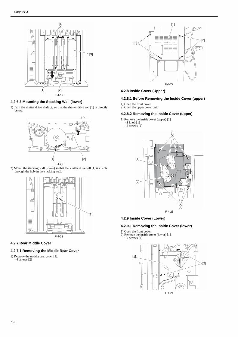
Chapter 4
4-4
F-4-19
4.2.6.3 Mounting the Stacking Wall (lower)0011-7706
1) Turn the shutter drive shaft [2] so that the shutter drive roll [1] is directlybelow.
F-4-202) Mount the stacking wall (lower) so that the shutter drive roll [1] is visible
through the hole in the stacking wall.
F-4-21
4.2.7 Rear Middle Cover
4.2.7.1 Removing the Middle Rear Cover0011-8396
1) Remove the middle rear cover [1].- 4 screws [2]
F-4-22
4.2.8 Inside Cover (Upper)
4.2.8.1 Before Removing the Inside Cover (upper)0011-8390
1) Open the front cover.2) Open the upper cover unit.
4.2.8.2 Removing the Inside Cover (upper)0011-8391
1) Remove the inside cover (upper) [1].- 1 knob [1]- 8 screws [2]
F-4-23
4.2.9 Inside Cover (Lower)
4.2.9.1 Removing the Inside Cover (lower)0011-8392
1) Open the front cover.2) Remove the inside cover (lower) [1].
- 2 screws [2]
F-4-24
[2]
[4]
[3]
[1]
[1] [2]
[1]
[2][2]
[1]
[3]
[3]
[1]
[2]
[1]
[2]

Chapter 4
4-5
4.3 Drive System
4.3.1 Staple Unit
4.3.1.1 Before Removing the Stapler0011-9212
1) Open the front cover.2) Open the upper cover unit.
3) Remove the inside cover (upper).(page 4-4)Reference[Removing theInside Cover (upper)]
4) Remove the inside cover (lower).(page 4-4)Reference[Removing theInside Cover (lower)]
4.3.1.2 Removing the Stapler0011-9213
1) Remove the switch PCB [1].- 2 screws [2]- 1 connector [3]- 1 edge saddle [4]
F-4-252) Push in the stapler unit [1] until it is as shown.
F-4-263) Remove the stapler unit [1].
- 1 connector [2]- 2 screws [3]
Be sure to take note of the positioning index [4] before detaching the staple.
F-4-27
4.3.2 Front Alignment Motor
4.3.2.1 Before Removing the Alignment Motor (frontÅj0011-7723
1) Remove the stacking wall (upper).(page 4-3)Reference[Removing theStacking Wall (upper)]
2) Remove the stacking wall (lower).(page 4-3)Reference[Removing theStacking Wall (lower)]
3) Remove the handling tray unit.(page 4-12)Reference[Removing theHandling Tray Unit]
4.3.2.2 Removing the Alignment Motor (front)0011-7724
1) Free the cable [2] from the 3 clamps [1], and disconnect the connector [3].
F-4-282) Free the cable [2] from the 2 clamps [1], and disconnect the connector [3].
F-4-293) Remove the handling tray plate unit [1].
- 1 screw [2] (loosen)- 1 belt [3]- 6 screws [4]- 2 positioning plates [5]
F-4-304) Shift the handling tray aligning plate (front) [1] in the direction of the ar-
row, and remove the screw [2] and the claw [3]; then, detach the handlingtray aligning plate (front).
[1]
[2]
[3][4]
[1]
[1]
[2]
[4]
[3]
[3]
[2]
[1]
[2]
[3]
[1]
[1]
[4] [4][5]
[2]
[3][4] [5] [4]

Chapter 4
4-6
F-4-315) Remove the handling tray (front) [1].
- 2 screws [2]
F-4-326) Loosen the screw [1], and free the belt [2] from the gear [3].
F-4-337) Remove the aligning motor (front) [1].
- 2 clamps [2]- 1 connector [3]- 2 screws [4]
F-4-34
4.3.3 Rear Alignment Motor
4.3.3.1 Before Removing the Alignment Motor (rear) 0011-7725
1) Remove the stacking wall (upper).(page 4-3)Reference[Removing theStacking Wall (upper)]
2) Remove the stacking wall (lower).(page 4-3)Reference[Removing theStacking Wall (lower)]
3) Remove the handling tray unit.(page 4-12)Reference[Removing theHandling Tray Unit]
4.3.3.2 Removing the Alignment Motor (rear)0011-7726
1) Free the cable [2] from the 3 clamps, and disconnect the connector [3].
F-4-352) Free the cable [2] connected to the 2 clamps [1], and disconnect the con-
nector [3].
F-4-363) Remove the handling plate unit [1].
- 1 screw [2] (loosen)- 1 screw [3]- 6 screws [4]- 2 positioning plates [5]
F-4-374) Shift the handling tray aligning plate (rear) [1] in the direction of the ar-
row, and remove the screw [2] and the claw [3]; then, detach the handlingtray aligning plate (rear).
F-4-38
[3] [1] [2]
[1] [2]
[2] [1][3]
[1]
[2]
[3]
[4]
[3]
[2]
[1]
[2]
[3]
[1]
[1]
[4] [4][5]
[2]
[3][4] [5] [4]
[3][1][2]

Chapter 4
4-7
5) Remove the handling tray (front) [1].- 2 screws [2]
F-4-396) Loosen the screw [1], and free the belt [2] from the gear [3].
F-4-407) Remove the alignment motor (rear) [1].
- 1 clamp [2]- 2 cable guides [3]- 1 connector [4]- 2 screws [5]
F-4-41
4.3.4 Tray Shift Motor
4.3.4.1 Removing the Tray A/B Lift Motor0011-7734
1) Remove the tray A/B cover [1].- 4 screws [2]
F-4-422) While supporting the tray from below, release the roll [1] in the direction
of the arrow; then, move it down until it stops.
F-4-433) Remove the screw [1], and open the connector cover [2] in the direction
of the arrow.
F-4-444) Disconnect the connector [1], and free the cable [4] from the edge saddle
[2] and the wire saddle [3].
F-4-455) Remove the tray A/B lift motor.
- 2 screws [2]- 1 belt [3]
F-4-46
4.3.5 Shift Motor
4.3.5.1 Before Removing the Shift Motor0011-8509
1) Disconnect the machine from the host machine side.2) Remove the upper rear cover (right).(page 4-2)Reference[Removing the
Upper Rear Cover (right)]3) Remove the upper rear cover (left).(page 4-2)Reference[Removing the
Upper Rear Cover (left)]4) Remove the middle rear cover.(page 4-4)Reference[Removing the Mid-
dle Rear Cover]
[1][2]
[3] [2] [1]
[1]
[2][3] [4]
[5]
[1]
[2]
[1]
[1] [2]
[1][2][3] [4]
[2]
[1][3]

Chapter 4
4-8
5) Remove the upper cover unit.(page 4-2)Reference[Removing the UpperCover Unit]
6) Remove the inside cover (upper).(page 4-4)Reference[Removing theInside Cover (upper)]
4.3.5.2 Removing the Shift Motor0011-8510
1) Remove the latch base support plate [1].- 2 screws [2]
F-4-472) Remove the transport stay (upper right) [1].
- 4 screws [2]
F-4-483) Remove the fan unit [1].
- 1 connector [2]- 2 screws [3]
F-4-494) Disconnect the 2 connectors [1], and remove the 2 screws [2].
F-4-505) Remove the detection drive assembly [1].
- 2 screws [2]
F-4-516) Remove the cable retainer [1], and disconnect the connector [2]; then, free
the cable [3] from the cable guide [4].
F-4-527) Insert a screwdriver [1] into the hole [1].
[1]
[2]
[1]
[2]
[2]
[1]
[2]
[3]
[2]
[1]
[1]
[2]
[1]
[2]
[3]
[4]

Chapter 4
4-9
F-4-538) Loosen the screw [1], and tighten the screw while the tension is removed.
F-4-549) Detach the belt [1] from the gear [2].
F-4-5510) Remove the 2 slide shafts [1] in the direction of the arrow.
- 2 screws [2]
F-4-5611) Detach the shift assembly [1] in the direction of the arrow.
When detaching the shift assembly, take care not to hit the clamp [2].
F-4-5712) Disconnect the connector [1], and free the cable [2] from the clamp [3]
and the 2 edge saddles [4].
F-4-5813) Remove the shift motor unit [1].
- 3 screws [2]
F-4-5914) Remove the shift motor [1].
- 2 screws [2]
F-4-60
[1]
[1] [2]
[1] [2]
[1][2]
[1] [2]
[1] [2] [3]
[4]
[1]
[2]
[1]
[2]

Chapter 4
4-10
4.3.6 Belt Controller Unit
4.3.6.1 Before Removing the Belt Controller Unit0011-8507
1) Remove the stacking wall (upper).(page 4-3)Reference[Removing theStacking Wall (upper)]
2) Remove the stacking wall (lower).(page 4-3)Reference[Removing theStacking Wall (lower)]
3) Remove the handling tray unit.(page 4-12)Reference[Removing theHandling Tray Unit]
4) Remove the middle rear cover.(page 4-4)Reference[Removing the Mid-dle Rear Cover]
4.3.6.2 Removing the Belt Controller Unit0011-8508
1) Loosen the screw [1].
F-4-612) Free the cable from the 4 clamps [1] and the edge saddle [2]; then, discon-
nect the 3 connectors [3].
F-4-623) Remove the 2 screws [1] found at the rear of the machine.
F-4-634) Remove the 2 screws [1] found at the front of the machine.
F-4-645) While removing the handling tray upper guide unit [1], detach the belt [3]
[4] from the 2 gears.
F-4-65
The belt [4] tends to slip off. Take care not to lose it.
6) Shift the belt variable lever [1] in the direction of the arrow.
F-4-667) Release the 2 roll guides [1] in the direction of the arrow, and detach the
2 belts [2] from the belt variable lever [3].
[1]
[1]
[1]
[2]
[3]
[3]
[3]
[1]
[1]
[1]
[2]
[3]
[4]
[1]
[1]

Chapter 4
4-11
F-4-678) Remove the 3 E-rings [1], shift [2], and bushing [4].
F-4-689) Remove the E-ring [1] and the bushing [2].
F-4-6910) Remove the belt controller unit [1].
- 2 screws [2]
F-4-70
Unite the guide side [3] of a guide lever (before) [1] and a guide lever (after)[2]. After that, it is a belt [4]. Two pieces are attached.
F-4-71
4.4 Document Feeding System
4.4.1 Stack Delivery Roller
4.4.1.1 Before Removing the Stack Delivery Upper Roller0011-7818
1) Remove the stacking wall (upper).2) Remove the stacking wall (lower).(page 4-3)Reference[Removing the
Stacking Wall (lower)]3) Remove the handling tray unit.(page 4-12)Reference[Removing the
Handling Tray Unit]
4.4.1.2 Removing the Stack Delivery Upper Roller0011-7819
1) Remove the tension springs [1].
F-4-722) Orient the handling tray unit [1] as shown.
[1]
[2]
[2]
[3]
[1]
[1]
[2]
[3]
[4]
[1][2]
[1][2] [2]
[1]
[2]
[3]
[3]
[4]
[2] [1]
[1] [1]

Chapter 4
4-12
F-4-733) Remove the belt [1], E-ring [2], gear [3], parallel pin [4], and plate [5].
F-4-744) Remove the ball bearing [1], washer [2]; E-ring [3], and ball bearing [4].
F-4-755) Remove the ball bearing [1] in downward direction, detaching the delivery
roller [2] at the same time.
F-4-766) Detach the E-ring [2] and the ball bearing [3] from the stack delivery roller
[1].
F-4-77
4.4.2 Process Tray Assembly
4.4.2.1 Before Removing the Handling Tray Unit0011-7707
1) Remove the stacking wall (upper).(page 4-3)Reference[Removing theStacking Wall (upper)]
2) Remove the stacking wall (lower).(page 4-3)Reference[Removing theStacking Wall (lower)]
4.4.2.2 Removing the Handling Tray Unit0011-7708
1) Remove the handling bin (front) [1] and the handling bin (rear) [2].- 2 screws [3]
F-4-782) Turn the knob [1] clockwise so that the rear edge drop guide [2] is at its
lowest position.
[1]
[1] [2]
[3]
[4][5]
[1]
[2]
[2]
[4]
[3]
[1]
[2]
[1]
[2]
[3]
[1] [2][3]

Chapter 4
4-13
F-4-793) Remove the handling tray unit [1].
- 6 connectors [2]- 4 screws [3]
F-4-80
A guide [2] is attached so that it may not run aground on a lever [1].
F-4-81
4.4.3 Process Tray
4.4.3.1 Before Removing the Handling Tray (front/rear)0011-7716
1) Remove the stacking wall (upper).(page 4-3)Reference[Removing theStacking Wall (upper)]
2) Remove the stacking wall (lower).(page 4-3)Reference[Removing theStacking Wall (lower)]
3) Remove the handling tray unit.(page 4-12)Reference[Removing theHandling Tray Unit]
4.4.3.2 Removing the Handling Tray (front)0011-7717
1) Shift the handling tray aligning plate (front) [1] in the direction of the ar-row; then, remove the screw [2] and the claw [3] to detach the handlingtray aligning plate (front).
F-4-822) Remove the handling tray (front) [1].
- 2 screws [2]
[A]
[1]
[2]
[1]
[3][3]
[2]
[1][2][1][2]
[3] [1] [2]

Chapter 4
4-14
F-4-83
4.4.3.3 Removing the Handling Tray (rear)0011-7718
1) Shift the handling tray aligning plate (rear) [1] in the direction of the ar-row; then, remove the screw [2] and the claw [3] to detach the handlingtray aligning plate (rear).
F-4-842) Remove the handling tray (rear) [1].
- 2 screws [2]
F-4-85
4.4.4 Feed Belt
4.4.4.1 Before Removing the Transport Belt0011-8381
1) Remove the stacking wall (upper).2) Remove the stacking plate (lower).(page 4-3)Reference[Removing the
Stacking Wall (lower)]3) Remove the handling tray unit.(page 4-12)Reference[Removing the
Handling Tray Unit]
4.4.4.2 Removing the Transport Belt0011-8382
1) Remove the protective cover [1].- 1 screw [2]
F-4-862) Loosen the screw [1], and shift the coupling (rear) [2] to the left.
F-4-873) Turn the coupling (front) [1] so that the screw is at the front; then, loosen
the screw, and shift the coupling (front) to the right.
F-4-884) Shift the transport belt release unit [1] toward the rear so that the transport
belt is not engaged.
F-4-895) Release the roll guide [1], and detach the transport roll [2] from the shaft
together with the belt.
[1] [2]
[2] [1] [3]
[1][2]
[1]
[2]
[1] [2]
[2][1]
[1]

Chapter 4
4-15
F-4-906) Detach the transport belt (rear) [1] by moving it through the coupling.
F-4-917) If the transport belt at the front must be detached, perform steps 8) and 9)
at the front.
4.4.5 Paddle Unit
4.4.5.1 Before Removing the Paddle Unit0011-7713
1) Remove the stacking plate (upper).(page 4-3)Reference[Removing theStacking Wall (upper)]
2) Remove the stacking plate (lower).(page 4-3)Reference[Removing theStacking Wall (lower)]
3) Remove the handling tray unit.(page 4-12)Reference[Removing theHandling Tray Unit]
4.4.5.2 Removing the Paddle Unit0011-7714
1) Remove the 3 paddle units [1].- 3 screws [2]
F-4-92
4.4.6 Paddle
4.4.6.1 Before Removing the Paddle0011-7710
1) Remove the stacking plate (upper).(page 4-3)Reference[Removing theStacking Wall (upper)]
2) Remove the stacking plate (lower).(page 4-3)Reference[Removing theStacking Wall (lower)]
3) Remove the handling tray unit.(page 4-12)Reference[Removing theHandling Tray Unit]
4) Remove the paddle unit.(page 4-15)Reference[Before Removing thePaddle Unit]
4.4.6.2 Removing the Paddle0011-7712
1) Release the 2 claws [1], and detach the paddle retaining roll [2] to detachthe paddle [3].
F-4-93
4.4.7 Tray Unit
4.4.7.1 Before Removing the Tray A/B Unit0011-8490
1) Remove the upper rear cover (right).(page 4-2)Reference[Removing theUpper Rear Cover (right)]
2) Remove the upper rear cover (left).(page 4-2)Reference[Removing theUpper Rear Cover (left)]
3) Open the front cover.4) Open the upper cover unit.
4.4.7.2 Removing the Tray A/B Unit0011-7727
MEMO:If the tray B unit must be removed, remove the tray A unit first.
1. Removing the Tray A Unit1) Remove the support cover [1].
- claw [2]
F-4-942) Remove the support plate [1].
- 4 screws [2]
[1] [2]
[1]
[1]
[2]
[2]
[3]
[1]
[1]
[1][2]

Chapter 4
4-16
F-4-953) Remove the stopper[1]
- screw [2]
F-4-964) Remove the screw [1], and disconnect the 2 connectors [2].
F-4-975) Remove the 2 screws [1], and lead out the cable [2] in the direction of the
arrow.
F-4-986) Remove the tray A cover [1]
- 4 screws [2]
F-4-997) Lift the tray A unit [1] to detach.
F-4-100
2. Removing the Tray B Unit1) Remove the stopper (lower) [1].
- 1 screw [2]
F-4-1012) Remove the screw [1], and disconnect the connector [2].
F-4-1023) Remove the 2 screws [1], and lead out the cable [2] in the direction of the
[1]
[2]
[2]
[2]
[1]
[1]
[2]
[2][1]
[1]
[2]
[1]
[2]
[1]
[1]
[2]

Chapter 4
4-17
arrow.
F-4-1034) Remove the tray B cover [1].
- 4 screws [2]
F-4-1045) Lift the tray B unit [1] to detach.
F-4-105
4.4.7.3 Points to Note About the Tray A/B Cable0011-7736
When mounting the tray A/B unit, take care so that the cables will not be-come tangled.
F-4-106
4.4.7.4 Points to Note When Handling the Stacking Wall Rail
0011-7737
Take care not to damage the stacking rail [1]. The presence of scratches or
dents can affect stacking performance. If soiling is found, clean it with al-cohol.
F-4-107
4.5 Electrical System
4.5.1 Finisher Controller PCB
4.5.1.1 Finisher Controller PCB
4.5.1.1.1 Before Removing the Finisher Controller PCB
0011-84931) Remove the middle rear cover. (page 4-4)Reference[Removing the
Middle Rear Cover]2) Remove the lower rear cover.(page 4-1)Reference[Removing the Low
Rear Cover]
4.5.1.1.2 Removing the Finisher Controller PCB
0011-77401) Remove the finisher controller PCB [1].
- 24 connectors (all)- 4 screws [2]
F-4-108
4.5.2 Static Charge Eliminator
4.5.2.1 Removing the Stack Edging Roller Static Eliminator
0011-7784
1) Remove the 2 stack edging roller stack eliminators [1].- 4 screws [2]
[2]
[1]
[1]
[2]
[1]
[1]
[1]
[1]
[2][2]

Chapter 4
4-18
F-4-109
4.5.2.2 Before Removing the Static Eliminator (upper delivery slot)
0011-7787
1) Remove the upper rear cover (right).2) Remove the upper rear cover (left). (page 4-2)Reference[Removing the
Upper Rear Cover (left)]3) Remove the middle rear cover. (page 4-4)Reference[Removing the
Middle Rear Cover]4) Remove the upper cover unit.(page 4-2)Reference[Removing the Upper
Cover Unit]
4.5.2.3 Removing the Stack Eliminator (upper delivery slot)
0011-7788
1) Remove the buffer upper cover assembly [1].- 1 reuse band [2]- 4 screws [3]
F-4-1102) Remove the 2 static eliminators (upper delivery slot) [1].
- 4 screws [2]
F-4-111
4.5.2.4 Before Removing the Stack Eliminator (inside delivery guide/inside delivery roller)
0011-7802
1) Remove the stacking wall (upper).(page 4-3)Reference[Removing theStacking Wall (upper)]
2) Remove the stacking wall (lower).(page 4-3)Reference[Removing theStacking Wall (lower)]
3) Remove the handling tray unit.(page 4-12)Reference[Removing theHandling Tray Unit]
4.5.2.5 Removing the Stack Eliminator (inside delivery guide)
0011-7807
1) Remove the 2 static eliminators (inside delivery guide) [1].- 4 screws [2]
F-4-112
4.5.2.6 Removing the Static Eliminator (inside delivery roller)
0011-7810
1) Remove the 2 static eliminators (inside delivery roller).- 2 screws [2]
F-4-113
4.5.3 Horizontal Registration Sensor Unit
4.5.3.1 Before Removing the Horizontal Registration Sensor Unit
0011-8542
1) Separate the machine from the host machine side.(page 4-1)Refer-ence[Disconnecting from the Host Machine]
2) Remove the upper rear cover (right).(page 4-2)Reference[Removing theUpper Rear Cover (right)]
3) Remove the upper rear cover (left).(page 4-2)Reference[Removing theUpper Rear Cover (left)]
4) Remove the middle rear cover. (page 4-4)Reference[Removing theMiddle Rear Cover]
5) Remove the upper cover unit.(page 4-2)Reference[Removing the UpperCover Unit]
6) Remove the middle rear cover. (page 4-4)Reference[Removing theMiddle Rear Cover]
4.5.3.2 Removing the Horizontal Registration Sensor Unit0011-8545
1) Remove the fan unit [1].- 1 connector [2]- 2 screws [3]
F-4-1142) Disconnect the 2 connectors [1], and remove the 2 screws [2].
[2][1][2]
[3][3]
[2]
[1]
[1]
[2] [2]
[2]
[1]
[1] [1][2]
[1]
[2]
[3]

Chapter 4
4-19
F-4-1153) Remove the detection drive assembly [1].
- 2 screws [2]
F-4-1164) Disconnect the connector [1], and free the cable [2] from the 3 cable
guides [3] and the edge saddle [4].5) Remove the 2 screws [5].
F-4-1176) Remove the horizontal registration sensor unit [1] in the direction of the
arrow.
F-4-118
[2]
[1]
[1][2]
[1]
[2]
[3][4]
[5]
[1]


Chapter 5 Maintenance


Contents
Contents
5.1 User Maintenance ..........................................................................................................................................................5-15.1.1 User Maintenance Items (finisher)............................................................................................................................................... 5-1
5.2 Maintenance and Inspection...........................................................................................................................................5-15.2.1 Periodically Replaced Parts ......................................................................................................................................................... 5-1
5.2.1.1 Periodically Replaced Parts in the Finisher ....................................................................................................................................................5-15.2.1.2 Periodically Replaced Parts in the Saddle Finisher.........................................................................................................................................5-1
5.2.2 Durables ....................................................................................................................................................................................... 5-25.2.2.1 Durables in the Finisher ..................................................................................................................................................................................5-25.2.2.2 Durables in the Saddle Stitcher .......................................................................................................................................................................5-2
5.2.3 Periodical Servicing ..................................................................................................................................................................... 5-25.2.3.1 Scheduled Servicing for the Finisher ..............................................................................................................................................................5-25.2.3.2 Scheduled Servicing for the Saddle Stitcher ...................................................................................................................................................5-2
5.3 Adjustment .....................................................................................................................................................................5-35.3.1 Basic Adjustment ......................................................................................................................................................................... 5-3
5.3.1.1 Adjusting the Height .......................................................................................................................................................................................5-35.3.1.2 Adjusting the Tilt ............................................................................................................................................................................................5-45.3.1.3 Adjusting the Horizontal Registration/Angle..................................................................................................................................................5-55.3.1.4 Adjusting the Horizontal Registration/Angle (if a paper folding unit has been installed)..............................................................................5-75.3.1.5 Adjusting the Sensor Intensity ........................................................................................................................................................................5-8
5.3.2 Adjustment at Time of Parts Replacement ................................................................................................................................ 5-105.3.2.1 Adjusting the Tray A/B Position...................................................................................................................................................................5-105.3.2.2 Adjusting the Angle of the Aligning Plate (orthogonal) ...............................................................................................................................5-105.3.2.3 Adjusting the Stapler Position.......................................................................................................................................................................5-105.3.2.4 Adjusting the Speed of the Swing Guide ......................................................................................................................................................5-115.3.2.5 Adjusting the Aligning Plate Width..............................................................................................................................................................5-115.3.2.6 Adjusting the Transport Belt Position...........................................................................................................................................................5-135.3.2.7 Adjusting the Stapling Position (rear 1-point) ..............................................................................................................................................5-145.3.2.8 Adjusting the Stapling Position (front 1-point).............................................................................................................................................5-165.3.2.9 usting the Stapling Position (2-point) ...........................................................................................................................................................5-175.3.2.10 Adjusting the Delivery of Stapled Stacks (lower delivery) ........................................................................................................................5-195.3.2.11 Adjustment of EEPROM (IC107) on the Finisher Controller PCB After Replacement.............................................................................5-20
5.3.3 Other .......................................................................................................................................................................................... 5-225.3.3.1 Service Mode (by DIP switch)<Incerter> .....................................................................................................................................................5-22
5.4 Troubleshooting ...........................................................................................................................................................5-235.4.1 Malfunction................................................................................................................................................................................ 5-23
5.4.1.1 Malfunction/Faulty Detection .......................................................................................................................................................................5-235.4.1.1.1 The output is sent to tray B even when tray A is selected. ...................................................................................................................5-235.4.1.1.2 Remedy for EEPROM Problem on Finisher Controller PCB ..............................................................................................................5-23
5.5 Outline of Electrical Components................................................................................................................................5-265.5.1 Sensors (Finisher Unit) .............................................................................................................................................................. 5-265.5.2 Microswitches (Finisher Unit) ................................................................................................................................................... 5-295.5.3 Solenoids (Finisher Unit) ........................................................................................................................................................... 5-305.5.4 Motors (Finisher Unit) ............................................................................................................................................................... 5-325.5.5 Fans (Finisher Unit) ................................................................................................................................................................... 5-34
5.6 Variable Resistors (VR), Light-Emitting Diodes (LED), and Check Pins by PCB.....................................................5-345.6.1 Overview.................................................................................................................................................................................... 5-345.6.2 Finisher Controller PCB ............................................................................................................................................................ 5-35
5.7 Service Tools................................................................................................................................................................5-355.7.1 Solvents and Oils ....................................................................................................................................................................... 5-35


Chapter 5
5-1
5.1 User Maintenance
5.1.1 User Maintenance Items (finisher)0011-3012
T-5-1
5.2 Maintenance and Inspection
5.2.1 Periodically Replaced Parts
5.2.1.1 Periodically Replaced Parts in the Finisher0011-3015
The finisher does not have a part that requires periodical replacement.
5.2.1.2 Periodically Replaced Parts in the Saddle Finisher0011-3016
The saddle finisher does not have a part that requires periodical replacement.
No. Item Timing1 staple cartridge (replacement) when prompted (in host machine control panel)
2 waste staple (disposal) when prompted (in host machine control panel)

Chapter 5
5-2
5.2.2 Durables
5.2.2.1 Durables in the Finisher0011-3017
Some parts of the machine may require replacement once or more over the period of product warranty because of deterioration or damage. Replace them as neces-sary.
T-5-2
5.2.2.2 Durables in the Saddle Stitcher0011-3032
Some parts of the machine may require replacement once or more over the period of product warranty because of deterioration or damage. Replace them as neces-sary.
T-5-3
5.2.3 Periodical Servicing
5.2.3.1 Scheduled Servicing for the Finisher0011-3033
The finisher does not have items that require scheduled servicing.
5.2.3.2 Scheduled Servicing for the Saddle Stitcher0011-3034
The saddle stitcher does not have items that require scheduled serving.
as of November 2005No. Parts name Parts number Q'ty Life Remarks1 Stapler FC6-6222-000
1500,000 times A single cartridge is good
for about 5000 operations.2 Roller belt FB5-9103-000 2 1,000,000
pages4 Stack edging roller static
eliminatorFC6-6134-000 1 1,000,000
pages5 Static eliminator FC6-6341-000 1 1,000,000
pages6 Static eliminator FC6-5864-000 2 1,000,000
pages7 Static eliminator FC6-6101-000 1 1,000,000
pages
as of November 2005No. Parts name Parts number Q'ty Life Remarks1 Stitcher FM2-6618-000
1500,000 times
A single cartridge is good for about 5000 operations.
2 Static eliminator (T2) FL2-3655-000 1 1,000,000 pages3 Flapper static eliminator FL2-3656-000 1 1,000,000 pages4 Shift roller FL2-3692-000 1 1,000,000 pages5 Paper static eliminator FL2-3654-000 1 1,000,000 pages

Chapter 5
5-3
5.3 Adjustment
5.3.1 Basic Adjustment
5.3.1.1 Adjusting the Height0011-8123
If jams start to occur often, adjust the height of the machine as follows:1. Checking the Height1) Check the height of the finisher and the host machine. Be sure that the dif-
ference in height between the right top surface [1] of the finisher and theleft top surface [2] of the host machine is +/-2 mm.
F-5-12) If the difference is +/-2 mm or more, adjust the height.
In order to adjusting the height, adjust four casters [1] shown in the figure.
F-5-2
2. Adjusting the Height1) Disconnect the finisher from the host machine.2) Detach the spanner [1] connected to the front cover.
- 1 screw [2]
F-5-3
3) In the case of the Finisher-V1, remove the caster cover [1].- 1 screw [2]
F-5-44) In the case of the Saddle Finbserh-V2, detach the saddle inside cover (low-
er) [1].- 1 screw [2]- 1 knob [3]- 3 screws [4]
F-5-55) Remove the 2 caster covers [1] from the left side. (The illustration shows
the saddle finisher.)- 2 screws [2]
F-5-66) Measure the height [A] from the caster mounted surface to the upper sur-
face of bottom plate using a scale or the like and check if the height is 84.6+/- 0.5 mm.
F-5-7
[1] [2]
[1]
[1]
[1]
[2]
[1]
[2]
[1]
[2] [3]
[4]
[4]
[2]
[1]
84.6 0.5mm[A]

Chapter 5
5-4
7) Loosen the fixing nut [1] of the scanner by turning the spanner (large) [2]in the direction of [A].
F-5-8
When loosening the caster fixing nut [1] on the front of the saddle finisher,be sure to fit the spanner [3] through the gap below the saddle assembly baseplate [2].
F-5-9
8) Turn the adjusting bolt [1] with a spanner (small) [2]. Adjusting the heightmeasured at step 6) so that it becomes 84.6 +/-0.5 mm.- to raise, turn in the direction of [A].- to lower, turn in the direction of [B]. (A single full turn causes a change of about 1.75 mm.)
F-5-109) Tighten the fixing nut [1] in the direction of [B].
F-5-1110) Likewise, adjust the remaining 3 casters.11) Connect the finisher to the host machine, and check the height.
If the difference is +/-2 mm, mount the removed parts such as the cover.Otherwise, repeat the adjustment procedure.
5.3.1.2 Adjusting the Tilt0012-5983
Finisher may tilt and it may be required to adjusting the tilt depending on thefloor condition of installation site. Go through the following to make a checkand make adjustments as needed.
1. Checking the Tilt1) Check the tilt of the finisher.
Check if a clearance [1] between the finisher and copier is 5+/-0.3 mm.
F-5-122) If the clearance is over 5+/-0.3 mm, need to adjusting the tilt.
In order to adjusting the tilt, adjust two casters [1] shown in the figure.
F-5-13
2. Adjusting the Tilt1) Remove the 2 caster covers [1] from the left side. (The illustration shows
the saddle finisher.)- 2 screws [2]
F-5-142) Loosen the fixing nut [1] of the scanner by turning the spanner (large) [2]
in the direction of [A].
[1]
[2]
[A]
[1]
[2]
[3]
[1]
[2]
[A]
[B]
[1]
[B]
[1]
[1]
[1]
[2]
[1]

Chapter 5
5-5
F-5-153) Turn the adjusting bolt [1] with a spanner (small) [2] so that the tilt be-
comes 5+/-0.3 mm.- When reducing the tilt: Turn the bolt in the direction of [A]- When increasing the tilt: Turn the bolt in the direction of [B] (A single full turn causes a change of about 1.75 mm.)
F-5-164) Tighten the fixing nut [1] in the direction of [B].
F-5-175) Similarly, adjust the other caster.6) Mount the removed caster covers.
5.3.1.3 Adjusting the Horizontal Registration/Angle0011-8125
If the vibration is excessive (i.e., the horizontal registration unit shifts exces-sively), or the skew is excessive on this machine, adjust the horizontal regis-tration/ skew correction as follows:
1. Checking the Adjustment Value1) Turn on the finisher and then the host machine.2) Open the front cover, and insert the door switch actuator into the door
switch [1].
F-5-183) Remove the switch cover [1] of the inside cover (lower).
- 1 screw [2]
F-5-194) Set the DIP switch SW382 [1] on the switch PCB as shown (1, 4, 6, and 8
at ON), and press the enter button (SW385) [2]; in response, the LED [3]will flash '0'.
F-5-205) Place a single sheet of A4/LTR paper, and select ADF or copyboard mode;
then, set '3' as the copy count, and execute printing.6) Check the horizontal registration/angle adjustment value indicated by the
LED [1].The indication will be 'A' -> 'horizontal registration adjustment value' ->'b' -> 'skew adjustment value'; take note of the values.- horizontal registration adjustment value (reference only): -3 to +3 mm(1 index: equivalent of 1 mm)- skew adjustment value (reference only); -2 to +2 mm (1 index:equivalent of 1 mm)
[1]
[2]
[A]
[1]
[2]
[A]
[B]
[1]
[B]
[1]
[2]
[1]
SW382
SW381
SW383
(-) (+) ENTER
SW384 SW385
DS
P38
1
[3][1]
[2]

Chapter 5
5-6
F-5-217) Press the enter button to end adjustment mode.8) Turn off the host machine and then the finisher in sequence.
2. Adjusting the Horizontal Registration1) Disconnect the finisher from the host machine.2) Loosen the 2 screws [2] on the positioning plate [1] found on the right
side.3) If the value recorded is on the + side, move the plate in the direction of [A]
and tighten the screw [2].If the value recorded is on the - side, on the other hand, move the plate inthe direction of [B] and tighten the screw [2].
F-5-223. Adjusting the Angle
If the angle is as indicated, start with step 7).1) Lift the upper cover [1], and detach the inside cover (upper) [2].
- 1 knob [3]- 8 screws [4]
F-5-232) Loosen the 2 screws [2] on the latch base (front) [1].3) If the value recorded is on the + side, move the base in the direction of [A]
and tighten the screw [2].If the value recorded is on the - side, on the other hand, move the base inthe direction of [B] and tighten the screw [2].
Make sure that the total of the indexes over which the latch base (front, rear)is moved is between -2 and +2 mm.
F-5-244) Remove the middle rear cover [1].
- 4 screws [2]
F-5-255) Loosen the 2 screws [2] on the latch base (rear) [1].
SW382
SW381
SW383
(-) (+) ENTER
SW384 SW385
DS
P38
1
[1]
[1]
[2]
[A][B]
[1]
[2]
[3]
[4]
[4]
[B][A]
[1]
[2]
[2][2]
[1]

Chapter 5
5-7
6) If the value recorded is on the + side, move the base in the direction of [A]and tighten the screw [2].If the value recorded is on the - side, on the other hand, move the base inthe direction of [B] and tighten the screw [2].
Make sure that the total of the indexes over which the latch base (front, rear)has been moved is between -2 and +2 mm.
F-5-267) Connect the finisher and the host machine.8) Turn on the finisher and the host machine in sequence.9) Check the adjustment values once again.
If the adjustment value indicated by the LED is within a specific range,press the ENTER key to end adjustment mode. Otherwise, go through thesteps for a second time; if the result is more or less the indicated value(reference only), end the work.
10) Put the DIP switch back to its initial settings, and attach the covers andparts you have removed.
5.3.1.4 Adjusting the Horizontal Registration/Angle (if a paper folding unit has been installed)
0013-4476
If the vibration is excessive (i.e., the horizontal registration unit shifts exces-sively), or the skew is excessive on this machine, adjust the horizontal regis-tration/ skew correction as follows: (if a paper holding unit has been installed)
1. Checking the Adjustment Values1) Turn on the finisher and the host machine in the order indicated.2) Open the front cover, and fit the door switch actuator into the door switch
[1].
F-5-273) Remove the switch cover [1] of the inside cover (lower).
- 1 screw [2]
F-5-284) Set the DIP switch SW382 [1] on the switch PCB as shown (1, 4, 6, 8:
ON), and press the ENTER (SW385) button [2] so that LED [3] goes on('0').
F-5-295) Place a single sheet of A4/LTR paper, and select ADF or copyboard mode;
then, set '3' as the copy count, and execute printing.6) See that the LED [1] indicates the horizontal registration/skew adjustment
value.The indication will be 'A' -> 'horizontal registration adjustment value' ->'b' -> 'skew adjustment value'; take note of the values.- horizontal registration adjustment value (reference only): -3 to +3 mm(1 index: equivalent of 1 mm)- skew adjustment value (reference only); -2 to +2 mm (1 adjustingspacer: equivalent of 1 mm)
F-5-307) Press the ENTER button to end adjustment mode.
- If the adjustment value (reference only) is as indicated, put the DIPswitch back to its initial setting.- If the adjustment value (reference only) is not as indicated, on the otherhand, perform the instructions under "2. Horizontal RegistrationAdjustment" or "3. Skew Adjustment".
8) Turn off the host machine and then the finisher in the order indicated.
[B][A]
[1]
[2]
[1]
[2]
[1]
SW382
SW381
SW383
(-) (+) ENTER
SW384 SW385
DS
P38
1
[3][1]
[2]
SW382
SW381
SW383
(-) (+) ENTER
SW384 SW385
DS
P38
1
[1]

Chapter 5
5-8
2. Horizontal Registration Adjustment1) Remove the front cover and the rear cover, and disconnect the host ma-
chine and the folder unit.2) Loosen the 2 screws [2] of the positioning plate [1] found on the right side.3) If the adjustment value is a '+' value, move it in the direction of [A], and
tighten the screw [2].If the value checked was a '-' value, on the other hand, move the plate inthe direction of [B], and tighten the screws [2]. (1 memory -> Comparableto 1mm)
F-5-314) Loosen the 2 screws [2] on the positioning pin [1] found on the right side.5) Move the plate in the direction and over the distance (number of indexes)
used in step 3); then, tighten the screws [2].
F-5-32
3. Skew AdjustmentIf the skew adjustment value is as indicated, go to step 5).
1) If the adjustment value is a '+' value, remove the latch plate [1] and thefolder pin plate [2] from the front of the host machine. (The removedscrews will no longer be used.)
2) Fit an adjusting spacer [3] between the host machine and the latch plate[1].- 2 screws (RS tightening; M4X12; white) [4]
A single adjusting spacer [3] enables adjustment up to +1 mm. Use up to 3spacers as needed.
F-5-333) If the adjustment value is a '-' value, remove the latch plate [1] from the
front of the machine. (The removed screw will no longer be used.)4) Fit an adjusting spacer [2] between the host machine and the latch plate
[1].- 2 screws (RS tightening; M4X12; white) [3]
A single adjusting spacer [2] enables adjustment of up to +1 mm. Use up to3 spacers as needed.
F-5-345) Connect the host machine and the folder unit.6) Turn on the finisher and then the host machine in the order indicated.7) Check the adjustment values once again.
If the adjustment value indicated by the LED is within a specific range,press the ENTER key to end adjustment mode. Otherwise, go through thesteps for a second time; if the result is more or less the indicated value(reference only), end the work.
8) Put the DIP switch back to its initial setting, and put back the covers youmay have removed.
5.3.1.5 Adjusting the Sensor Intensity0011-8877
Go through the following steps when installing the finisher or replacing spe-cific sensor:1) Turn on the finisher and the host machine in sequence.2) Open the front cover, and insert the door switch actuator into the door
switch [1].
[A][B]
[2]
[1]
[A][B]
[2]
[1]
[2][4]
[3]
[1]
[2]
[3]
[1]

Chapter 5
5-9
F-5-353) Insert a screwdriver [2] through the hole [1] in the bottom face of the tray;
then, disengage the tray in the direction of [A], and lower the tray A/B inthe direction of [B].
F-5-36
Be sure to lower the tray A/B [2] until it does not block the tray sensor (front/rear) [1].
F-5-37
4) Detach the inside cover (lower) and the switch cover [1].- 1 screw [2]
F-5-385) Set the DIP switch SW382 [1] of the switch PCB as shown (1: ON), and
press the enter button (SW385) [2] to start sensor intensity adjustment.
F-5-396) If the LED [1] indicates '0', the adjustment has been successful. Press the
enter button (SW385) [2] to end the sensor intensity adjustment.
F-5-407) If any of the sensors is faulty (i.e., the LED flashes '0'), press the +
(SW384) [1]/- (SW383) [2] button to find out the code number indicatedby the LED [3], and replace the faulty sensor.
T-5-4
[1]
[1]
[A] [B]
[2]
[1]
[2]
[2]
[1]
Code Sensor Name1 Buffer path 1 sensor PCBÅiUN13Åj2 Buffer path 2 sensor PCBÅiUN14Åj3 Lower path sensor PCBÅiUN24Åj4 Horizontal sensor PCBÅiUN12Åj5 Punch chip case full sensor PCBÅiPanch unit U1Åj6 Å` 8 Tray A paper surface sensor PCB ÅiUN16Åj
[2]
[1]
SW382
SW381
SW383
(-) (+) ENTER
SW384 SW385
DS
P38
1
[2]
[1]
SW382
SW381
SW383
(-) (+) ENTER
SW384 SW385
DS
P38
1
[2]
[1]

Chapter 5
5-10
5.3.2 Adjustment at Time of Parts Replacement
5.3.2.1 Adjusting the Tray A/B Position0011-7481
Go through the following steps if you have replaced the tray A or B so thatthe tray is horizontal:1) Holding the tray horizontally, fit it to the support (left, right).
At this time, be sure that distance A (i.e., from the tip of the support [3]to the tray shaft [4]) is the same at the front [1] and the rear [2].
F-5-41
5.3.2.2 Adjusting the Angle of the Aligning Plate (orthogonal)
0011-7483
Go through the following steps if you have replaced the alignment motor ofthe intermediate handling tray assembly or the EEPROM of the finisher con-troller PCB:1) After mounting the intermediate handling tray assembly, loosen the 2
screws [2] on the aligning plate [1] of the assembly.
F-5-422) Fix the 2 paper edge stoppers [1] in place on the host machine using 2screws [2].
F-5-433) Place A4 paper [1] in the intermediate handling tray in the direction of thearrow. Make adjustments so that there is no gap between the paper edge [1]and the aligning plate [2]; then, fix the aligning plate using a screw [3].
F-5-44
5.3.2.3 Adjusting the Stapler Position0011-7484
Go through the following steps if you have replaced the stapler unit found inthe intermediate handling tray assembly:1) Mark the position [1] of the stapler unit before replacement.
2) Mount the new stapler unit [2] with reference to the marking [1], fixing
9ÅAAÅAb tray B paper surface sensor PCB ÅiUN18Åj
[3]
[4] [A]
[1]
[2]
[1][2] [2]
[2]
[1]
[3]
[2]
[2]
[C] [1]
[1]
[1]
Beforeadjustment
Afteradjustment

Chapter 5
5-11
it in place using 2 screws [3].
F-5-45
5.3.2.4 Adjusting the Speed of the Swing Guide0011-7506
Go through the following steps if you have replaced the swing guide motoror the EEPROM of the finisher controller PCB:1) Turn on the finisher.2) Turn on the host machine so that it will be in a standby state.3) Open the front door, and insert the door switch actuator into the door
switch [1].
F-5-464) Remove the screw [2], and detach the switch cover [1].
F-5-475) Set the DIP switch SW382 [1] on the switch PCB as follows:
F-5-486) Press the push switch SW385 [1] to start adjustment of the swing guide
speed. In a while, press the push switch SW385 [1]; if the LED [2] indicates '0',the adjustment has ended successfully.
F-5-497) If the LED indicates other than '0', the result is not good. Repeat the steps.
5.3.2.5 Adjusting the Aligning Plate Width0011-7510
Go through the following steps if you have replaced the front alignment mo-tor or the rear alignment motor or the EEPROM of the controller PCB:1) Turn on the finisher.2) Turn on the host machine so that it will be in a standby state.3) Open the front door, and insert the door switch actuator into the door
switch [1].
F-5-504) Remove the screw [2], and detach the switch cover [1].
[2][3]
[1]
[1]
[2]
[1]
SW382
SW381
SW383
(-) (+) ENTER
SW384 SW385
DS
P38
1
[1]
SW382
SW381
SW383
(-) (+) ENTER
SW384 SW385
DS
P38
1
[2]
[1]
[1]

Chapter 5
5-12
F-5-515) Set the DIP switch SW382 [1] on the switch PCB as follows:for A-Series,
F-5-52for L-Series,
F-5-536) Press the push switch SW3851 [1] to start adjustment of the front aligning
plate width.
F-5-547) Place A4 paper [1] in the intermediate handling tray. (Be sure to butt thepaper against the rear of the handling tray.)
F-5-558) Press the push switch SW383 [1] or SW384 [2] to store the new value.
A single press on SW383 will cause the LED [3] to indicate '-1', movingthe front aligning plate [4] by about 0.2 mm toward the front. On the otherhand, a single press on SW384 will cause the LED [3] to indicate '+1',moving the front aligning plate [4] by about 0.2 mm toward the rear.range of adjustment: +10 to -10 (unit: 0.2 mm)
[2]
[1]
SW382
SW381
SW383
(-) (+) ENTER
SW384 SW385
DS
P38
1
[1]
SW382
SW381
SW383
(-) (+) ENTER
SW384 SW385
DS
P38
1
[1]
SW382
SW381
SW383
(-) (+) ENTER
SW384 SW385
DS
P38
1
[1]
[1]

Chapter 5
5-13
F-5-569) Press the push switch SW385 [1] to store the distance of travel of the front
aligning plate.
F-5-5710) Check that there is no gap between the paper and the aligning plate as the
result of the foregoing steps. If there still is a gap, go back to step 8).
F-5-58
5.3.2.6 Adjusting the Transport Belt Position0011-7522
Go through the following steps if you have replaced the transport belt of theintermediate tray or there is displacement among the sheets of a deliveredstack:1) Turn on the finisher.2) Turn on the host machine so that it will be in a standby state.3) Open the front door, and insert the door switch actuator into the door
switch [1].
F-5-594) Remove the screw [2], and detach the switch cover [1].
F-5-605) Set the DIP switch SW382 [1] on the switch PCB as follows:
F-5-616) Press the push switch SW385 [1] to start adjustment of the transport belt
position.
SW382
SW381
SW383
(-) (+) ENTER
SW384 SW385
DS
P38
1
[1] [2]
[3]
[4]
SW382
SW381
SW383
(-) (+) ENTER
SW384 SW385
DS
P38
1
[1]
[2]
[1]
[1]
[2]
[1]
SW382
SW381
SW383
(-) (+) ENTER
SW384 SW385
DS
P38
1
[1]

Chapter 5
5-14
F-5-627) Press the push switch SW383 [1] or SW384 [2] to store the adjustmentvalue. A single press on SW383 will cause the LED to indicate '-1', closing up thedistance between the belt [4] and the paper [5] and, thus, increasing the re-tention by the belt. On the other hand, a single press on SW384 will causethe LED to indicate '+1', distancing the belt [4] and the paper [5] and, thus,decreasing the retention by the belt. (range: +4 to -4)
Reference:1. If wear has occurred on the transport belt or recycled paper (i.e., with highsurface resistance) is used, select a negative adjustment value (-1 to -4) to in-crease the retention.2. If dents have occurred in the edge of paper, select a positive adjustmentvalue (+1 to +4) to decrease the retention.
F-5-638) Press the push switch SW385 [1] to end adjustment of the transport belt.
If the LED [2] indicates '0', the adjustment has ended successfully.
F-5-649) If the LED indicates '0', on the other hand, the adjustment has failed. Re-
peat the foregoing steps.
5.3.2.7 Adjusting the Stapling Position (rear 1-point)0011-7524
Go through the following steps if there is displacement in the stapling posi-tion (rear 1-point) or if you have replaced the EEPROM of the finisher con-troller PCB:1) Turn on the finisher.2) Turn on the host machine so that it will be in a standby state.3) Open the front door, and insert the door switch actuator into the door
switch [1].
F-5-654) Remove the screw [2], and detach the switch cover [1].
F-5-665) Set the DIP switch SW382 [1] of the switch PCB as follows:
SW382
SW381
SW383
(-) (+) ENTER
SW384 SW385
DS
P38
1[1]
SW382
SW381
SW383
(-) (+) ENTER
SW384 SW385
DS
P38
1
[1] [2]
[3]
[4]
[5]
SW382
SW381
SW383
(-) (+) ENTER
SW384 SW385
DS
P38
1
[2]
[1]
[1]
[2]
[1]

Chapter 5
5-15
F-5-676) Press the push switch SW385 [1] to start adjustment of the stapling posi-
tion (rear 1-point).for A-Series,
F-5-68for L-Series,
F-5-697) Press the push switch SW383 [1] or SW384 [2] to store the adjustment
value.A single press on SW383 will cause the LED [3] to indicate '-1', movingthe stapling position toward the rear. On the other hand, a single press onSW384 will cause the LED [3] to indicate '+1', moving the stapling posi-tion toward the front.
range of adjustment: +20 to -20 (unit: 0.5 mm)
F-5-708) Press the push switch SW385 [1] to move the stapler to the rear.
F-5-719) Place A4 paper [1] in the intermediate handling tray. (Be sure to butt thepaper against the rear of the handling tray.) Thereafter, press the push switch SW385 to execute stapling.
F-5-7210) Check to see that the stapling position is 5 +/-2 mm [1] as a result of the
foregoing steps. Otherwise, go back to step 6).
SW382
SW381
SW383
(-) (+) ENTER
SW384 SW385
DS
P38
1
[1]
SW382
SW381
SW383
(-) (+) ENTER
SW384 SW385
DS
P38
1
[1]
SW382
SW381
SW383
(-) (+) ENTER
SW384 SW385
DS
P38
1
[1]
SW382
SW381
SW383
(-) (+) ENTER
SW384 SW385
DS
P38
1
[2] [1]
[3]
SW382
SW381
SW383
(-) (+) ENTER
SW384 SW385
DS
P38
1
[1]
[1]

Chapter 5
5-16
F-5-73
If the LED indicates a value other than '0', the adjustment is likely to havefailed. Start over.
5.3.2.8 Adjusting the Stapling Position (front 1-point)0011-7548
Go through the following steps if the stapling position (front 1-point) is dis-placed or if you have replaced the EEPROM of the finisher controller PCB:1) Turn on the finisher.2) Turn on the host machine so that it will be in a standby state.3) Open the front door, and insert the door switch actuator into the door
switch [1].
F-5-744) Remove the switch [2], and detach the switch cover [1].
F-5-755) Set the DIP switch SW382 [1] on the switch PCB as follows:for A-Series,
F-5-76for L-Series,
F-5-776) Press the push switch SW385 [1] to start adjustment of the stapling posi-
tion (front 1-point).
F-5-787) Press the push switch SW383 [1] or SW382 [3] to store the new adjust-
ment value. A press on SW383 causes the LED [3] to indicate '-1', moving the sta-pling position (front 1-point) toward the rear. On the other hand, a presson SW384 causes the LED [3] to indicate '+1', moving the stapling posi-tion toward the front.
range of adjustment: +20 to -20 (unit: 0.5 mm)
[1]
[1]
[2]
[1]
SW382
SW381
SW383
(-) (+) ENTER
SW384 SW385
DS
P38
1
[1]
SW382
SW381
SW383
(-) (+) ENTER
SW384 SW385
DS
P38
1
[1]
SW382
SW381
SW383
(-) (+) ENTER
SW384 SW385
DS
P38
1
[1]

Chapter 5
5-17
F-5-798) Press the push switch SW385 [1] to move the stapler toward the front.
F-5-809) Place A4 paper [1] in the intermediate handling tray. (Be sure to butt thepaper against the rear of the handling tray.)
F-5-8110) Check to make sure that the stapling position is 5 +/-2 mm [1] as a result
of the foregoing steps. Otherwise, go back to step 6).
F-5-82
If the LED indicates other than '0', the adjustment is likely to have failed.Start over.
5.3.2.9 usting the Stapling Position (2-point)0011-7767
Go through the following steps if there is displacement in stapling position(2-point) or if you have replaced the EEPROM of the finisher controllerPCB:1) Turn on the finisher.2) Turn on the host machine so that it will be in a standby state.3) Open the front door, and insert the door switch actuator into the door
switch [1].
F-5-834) Remove the screw [2], and detach the switch cover [1].
F-5-845) Set the DIP switch SW382 [1] on the switch PCB as follows:for A-Series,
SW382
SW381
SW383
(-) (+) ENTER
SW384 SW385
DS
P38
1
[1] [2]
[3]
SW382
SW381
SW383
(-) (+) ENTER
SW384 SW385
DS
P38
1
[1]
[1]
[1]
[1]
[2]
[1]

Chapter 5
5-18
F-5-85for L-Series,
F-5-866) Press the push switch SW385 [1] to start adjustment of stapling position
(2-point).
F-5-877) Press the push switch SW383 [1] or SW384 [2] to store the new adjust-
ment value.A single press on SW383 will cause the LED [3] to indicate '-1', movingthe stapling position (2-point) upward. On the other hand, a single presson SW384 will cause the LED [3] to indicate '+1', moving the stapling po-sition in downward direction.range of adjustment: +20 to -20 (unit: 0.5 mm)
F-5-888) Press the push switch SW385 [1] to move the stapler to the 2-point sta-
pling position.
F-5-899) Place A4 paper [1] in the intermediate handling tray. (Be sure to butt thepaper against the rear of the handling tray.)
F-5-90
SW382
SW381
SW383
(-) (+) ENTER
SW384 SW385
DS
P38
1
[1]
SW382
SW381
SW383
(-) (+) ENTER
SW384 SW385
DS
P38
1
[1]
SW382
SW381
SW383
(-) (+) ENTER
SW384 SW385
DS
P38
1
[1]
SW382
SW381
SW383
(-) (+) ENTER
SW384 SW385
DS
P38
1
[1] [2]
[3]
SW382
SW381
SW383
(-) (+) ENTER
SW384 SW385
DS
P38
1
[1]
[1]

Chapter 5
5-19
10) Check to see that the stapling position is as follows [1] as the result ofthe foregoing steps: for A-Series, 86.3 +/-4 mm; for L-Series, 73.7 +/-4mm. Otherwise, go back to step 6).
F-5-91
If the LED indicates other than '0', the adjustment is likely to have failed.Start over.
5.3.2.10 Adjusting the Delivery of Stapled Stacks (lower delivery)
0011-7556
Go through the following steps if there is displacement among sheets of astapled stack (lower delivery; cover, 1st to 3rd sheets) or if you have replacedthe EEPROM of the finisher controller PCB:1) Turn on the finisher.2) Turn on the host machine so that it will be in a standby state.3) Open the front door, and insert the door switch actuator into the door
switch [1].
F-5-924) Remove the screw [2], and detach the switch cover [1].
F-5-935) Set the DIP switch SW382 [1] on the switch PCB as follows:
F-5-946) Press the push switch SW385 [1] so that the LED [2] flashes '0', indicatingthat the machine is ready for adjustment.
F-5-957) Place 3 originals in the ADF, and set as follows on the control panel: A4,1 set (staple sort).8) Press the Start key on the control panel to execute copying.9) Open the upper cover, and measure the displacement (A: between 1st and
2nd sheets; B: between 2nd and 3rd sheets). Repeat this step 5 times, and see that the average of A and B is as indi-cated (2 +/-0.5 mm). If not, go through the following steps:
[1]
[1]
[2]
[1]
SW382
SW381
SW383
(-) (+) ENTER
SW384 SW385
DS
P38
1
[1]
SW382
SW381
SW383
(-) (+) ENTER
SW384 SW385
DS
P38
1
[2]
[1]

Chapter 5
5-20
F-5-96
F-5-97[1] 1st sheet[2] 2nd sheets[3] 3rd sheets
10) If A (between 1st and 2nd sheets) or B (between 2nd and 3rd sheets) isnot as indicated, go through the following: Press the push switch SW385 [1] so that the machine is in adjustmentmode for A (between 1st and 2nd sheets). Press the push switch SW383[2] to decrease the displacement, or press SW384 [3] to increase the dis-placement. (The LED [4] indicates the correction value.)range of adjustment: +30 to -30 (unit: 0.2 mm)
F-5-9811) If B (between 2nd and 3rd sheets) is not as indicated, go through the fol-
lowing: Press the push switch SW385 [1] so that the machine is in adjustmentmode for B (between 1st and 3rd sheets). Press the push switch SW382 [2] to decrease the displacement, or pressSW384 [3] to increase the displacement. (The LED [4] will indicate thecorrection value.)
range of adjustment: +30 to -30 (unit: 0.2 mm)Another press on SW385 will store the A/B correction value.
F-5-99
A press on the push switch SW385 while the LED is indicating '0' will causethe LED to indicate the A and B correction values in sequence.Pay attention so that you remain aware of which correction value you areworking on.
5.3.2.11 Adjustment of EEPROM (IC107) on the Finisher Controller PCB After Replacement
0013-8722
This adjustment must be carried out when the EEPROM (IC107) on the fin-isher controller PCB is replaced.1) Turn on the finisher.2) Turn on the copier and set the copier in a stand-by mode.3) Open the front door, and insert the door switch actuator into the door
switch [1].
F-5-1004) Detach the switch cover [1] by removing the screw [2].
[1][2][3]
[B] [A]
[1]
[2]
[3]
SW382
SW381
SW383
(-) (+) ENTER
SW384 SW385
DS
P38
1
[2] [3]
[4]
[1]
SW382
SW381
SW383
(-) (+) ENTER
SW384 SW385
DS
P38
1
[2] [3]
[4]
[1]
[1]

Chapter 5
5-21
F-5-1015) Set the DIP SW382 [1] on the Switch PCB as shown in the figure below.
EEPROM is initialized by pressing the switches in the order ofSW385,SW384,SW383, once for each.
F-5-1026) Make the following adjustments:-Sensor light intensity adjustment-Swing guide speed adjustment-Aligning plate width adjustment-Staple position adjustment (rear; 1-point binding)- Staple position adjustment (front; 1-point binding)- Staple position adjustment (2-point binding)- Staple bulk delivery adjustment (lower delivery)- Staple bulk delivery adjustment (saddle delivery)-Feeding belt position adjustment-Saddle leading edge stopper position adjustment-Saddle binding position adjustment-Saddle folding position adjustment-Punch hole position adjustment (in the direction of side registration)- Punch hole position adjustment (in the direction of feeding)
[2]
[1]
SW382
SW381
SW383
(-) (+) ENTER
SW384 SW385
DS
P38
1

Chapter 5
5-22
5.3.3 Other
5.3.3.1 Service Mode (by DIP switch)<Incerter>0013-3683
The machine is equipped with a set of service mode items used to adjust it orto run checks on operation. The items may be executed from the machine orfrom its host machine.- From the InserterSee Maintenance>VR, LED, and Check Pins>DIP Switch.- From the Finisher1) Open the finisher front cover; then, remove the screw [1] and the cover[2].2) Make adjustments and checks using the DIP switch [3] (SW382) and thepush switch [4] (SW383/SW384/SW385) found on the service PCB I.
F-5-103T-5-5
[1]
[2]
SW382
SW381
SW383
(-) (+) ENTER
SW384 SW385
[3]
[4]
DIP setting Item Description
driving the drive switchover motor Press ENTER to start. A press on + will start tray A, while a press on - will start tray B. Press ENTER to end.
driving tray pickup motor Press ENTER to start. A press on +/- will switch over the speed (250, 500, 1100 mm/sec). Press ENTER to end.
driving the feed motor Press ENTER to start (1100 mm/sec). Press ENTER to end.
driving the tray A lift motor Press ENTER to start (1100 mms/sec). Press ENTER to end.
driving the tray B lift motor
driving the tray registration clutch Press ENTER to start. It will stop automatically. (ON for 500 msec)
Ageing Press ENTER to start and repeat the following operations; press ENTER to end:tray A up>50 sheets in tray A>tray A down>tray B up>50 sheets in tray B>tray B down
SW382
SW382
SW382
SW382
SW382
SW382
SW382

Chapter 5
5-23
5.4 Troubleshooting
5.4.1 Malfunction
5.4.1.1 Malfunction/Faulty Detection
5.4.1.1.1 The output is sent to tray B even when tray A is selected.
0011-8041[Case Study]DescriptionEnabling the following in user mode will select tray B as the destination of output (large-capacity stacking mode): initial setup/registration>common spec set-up>large-capacity stacking mode.
Once the setting has been enabled (ON), th target of output will be tray B, regardless of the selection made on the control panel.Field RemedyDisable (OFF) 'large-capacity stacking mode' in user mode so that the target of output may freely be selected on the control panel.
5.4.1.1.2 Remedy for EEPROM Problem on Finisher Controller PCB
0013-8769Description The remedy in case 'E505' is displayed at the time of Finisher Controller PCB replacement is described below. Remedy in the Field With the following procedure, resolve the problem. 1) Turning off the copier. 2) Remove the old PCB from the finisher and mount the new PCB.
checking the sensors 1 Press ENTER to start. A press on +/- switches over sensors. Press ENTER to end.1. tray A paper placement sensor2. tray A pickup sensor3. tray A registration sensor4. tray A paper sensor5. tray B paper sensor 16. tray B paper sensor 27. tray B paper placement sensor8. tray B pickup sensor9. tray B registration sensorA press on the + switch to start the sensor in question. The sensor in question is indicated on the display (DSP381). If the sensor operation is normal, 1 goes on in response to the placement of paper, while it flashes when the paper is removed.
checking the sensors 2 Press ENTER to start. A press on +/- switches over sensors. Press ENTER to end.1. feed sensor2. not used3. feed sensor 24. tray A lower limit sensor5. tray B lower limit sensor6. drive switchover sensor7. not used8. upper cover open/closed sensor9. inserter open/closed sensorA press on the + switch moves the sensor in question. The sensor in question is indicated on the display (DSP381).
adjusting the tray A width (A4) 1) Set the DIP switch to suit the tray being adjusted and the paper configuration.2) Press ENTER.3) Place A4 or LTR paper in the upper or lower tray. (minimum width adjustment)4) Press the + switch.5) $6) Press the - switch.7) Press ENTER to end.
adjusting the tray B width (A4)
adjusting the tray A width (LTR)
adjusting the tray B width (LTR)
DIP setting Item Description
SW382
SW382
SW382
SW382
SW382
SW382

Chapter 5
5-24
3) Remove EEP-ROM (IC107) from the new PCB. (Do not throw the EEP-ROM away at this point.) 4) Remove EEP-ROM from the old PCB and set it into the socket (ICS1) on the new PCB. 5) Turn on the copier. If E505 is not displayed on the copier, it is the end of the procedure (The memory contents in the old PCB is backupped to the new PCB.) 6) If E505 is displayed, go on to the next step. (If E505 occurs once again, it is due to EEP-ROM fault. Memory backup using the old EEP-ROM is not succeeded.) 7) Turn off the copier, and replace the old EEP-ROM set into the socket on the new PCB to the new EEP-ROM.
8) Turn on the finisher once again.
9) Turn on the copier, and make it in the standby state. 10) Open the front door, and insert a door switch actuator into the door switch [1].
F-5-10411) Detach the switch cover [1] by removing the screw [2].
F-5-10512) Set the DIP SW382 [1] located on switch PCB as the following:
F-5-10613) Execute the following adjustment.Each press enables to execute initializing EEPROM from SW385 to SW383 in order.-Sensor light intensity adjustment-Swing guide speed adjustment-Aligning plate width adjustment-Stapling position adjustment (rear 1-point binding)-Stapling position adjustment (front 1-point binding)-Stapling position adjustment (2-point binding)-Stuck stapling delivery adjustment (bottom delivery)-Stuck stapling delivery adjustment (saddle delivery)-Feeding belt position adjustment -Saddle lead edge stopper position adjustment-Saddle binding position adjustment-Saddle folding position adjustment-Punch hole position adjustment (vertical registration direction)
[1]
[2]
[1]
SW382
SW381
SW383
(-) (+) ENTER
SW384 SW385
DS
P38
1

Chapter 5
5-25
-Punch hole position adjustment (feeding direction)

Chapter 5
5-26
5.5 Outline of Electrical Components
5.5.1 Sensors (Finisher Unit)0011-8659
F-5-107
PS32
PS33
PS34
PS29
PS28PS27
PS42
PS24
PS35
PS26
PS25
PS20
PS11
PS15
PS14
PS13
PS17PS16
PS23PS12PS22
PS18PS21
PS19
PS3
PS1
PS6PS7
PS4
PS8PS9
PS2
PS5
PS31
PS30

Chapter 5
5-27
T-5-6
Notation Name Description Parts No. Jam Error
PS1 front cover open sensor detects the state (open/closed) of the front cover
FK2-0149 1422
PS2 upper cover open/closed sensor
detects the state (open/closed) of the upper cover
FK2-0149 1422
PS3 inlet sensor detects paper at the inlet WG8-5736 1002/1103
PS4 shift unit trail edge sensor detects paper in the shift unit WG8-5736 1004/1105
PS5 upper delivery sensor detects paper in the upper delivery assembly
WG8-5736 100A/110B
PS6 lower delivery sensor detects paper in the lower delivery sensor
WG8-5736 100E/110F
PS7 horizontal registration HP sensor
detects the home position of the horizontal registration unit
FK2-0149 E566
PS8 shift roller unit HP sensor detects the home position of the shift roller unit
FK2-0149 E567
PS9 transport roller HP sensor detects the home position of the transport roller
FK2-0149 E568
PS11 front alignment HP sensor detects the home position of the front aligning plate
FK2-0149 E537
PS12 rear alignment HP sensor detects the home position of the rear aligning plate
FK2-0149 E530
PS13 assist HP sensor detects the home position of the assist unit
FK2-0149 E514
PS14 stack delivery auxiliary tray HP sensor
detects the home position of the stack delivery auxiliary tray
FK2-0149 E583
PS15 paper edge area 1 sensor detects paper in the area FK2-0149 E57A
PS16 paper edge area 2 sensor detects paper in the area FK2-0149 E57A
PS17 handling tray paper sensor detects paper in the handling tray FK2-0149
PS18 swing motor rotation sensor
detects the rotation of the swing motor
FK2-0149
PS19 shutter HP sensor detects home position of the shutter
FK2-0149 E584
PS20 paddle rotation HP sensor detects the home position of the paddle rotation
FK2-0149 E577
PS21 paddle lifter HP sensor detects the home position of the paddle lifter operation
FK2-0149 E577
PS22 swing guide closed sensor detects the opening operation of the swing guide
FK2-0149 E535
PS23 swing guide open sensor detects closing operation of the swing guide
FK2-0149 E535
PS24 paper trail edge push mechanism HP sensor
detects the home position of the paper trail edge push mechanism
FK2-0149 E57B
PS25 transport belt HP sensor detects the home position of the transport belt
FK2-0149 E578
PS26 upper guide HP sensor detects the home position of the upper guide
FK2-0149 E57C
PS27 stapling position HP sensor detects the home position of stapling
FK2-0149
PS28 stapling position sensor 1 detects stapling position FK2-0149
PS29 stapling position sensor 2 detects stapling position FK2-0149
PS30 stapling position sensor 3 detects stapling position FK2-0149
PS31 stapling position sensor 4 detects stapling position FK2-0149
PS32 tray A paper sensor detects paper in tray A FK2-0149 E540
PS33 tray B paper sensor detects paper in tray B FK2-0149 E542
PS34 tray A lifter motor rotation sensor
detects lifter operation of tray A FK2-0149 E540
PS35 tray B lifer motor rotation sensor
detects lifter operation of tray B FK2-0149 E542
PS42 staple waste case full sensor
detects the state (full) of the staple waste case
FK2-0149

Chapter 5
5-28
T-5-7
Notation Shift relay PCB Transport motor driver PCB Finisher controller PCB
PS1 J117
PS2 J117
PS3 J117
PS4 J463/J461 J278/J271 J118
PS5 J279/J271 J118
PS6 J116
PS7 J116
PS8 J116
PS9 J279/J271 J118
PS11 J257/J252 J104
PS12 J256/J252 J104
PS13 J256/J252 J104
PS14 J253/J252 J104
PS15 J257/J252 J104
PS16 J256/J252 J104
PS17 J256/J252 J104
PS18 J253/J252 J104
PS19 J253/J252 J104
PS20 J253/J252 J104
PS21 J253/J252 J104
PS22 J253/J252 J104
PS23 J253/J252 J104
PS24 J116
PS25 J263/J251 J104
PS26 J263/J251 J104
PS27 J114
PS28 J114
PS29 J114
PS30 J114
PS31 J114
PS32 J109
PS33 J108
PS34 J109
PS35 J108
PS42 J121

Chapter 5
5-29
5.5.2 Microswitches (Finisher Unit)0011-8661
F-5-108
CB1
SW1
MSW2
MSW1
MSW4
MSW6
MSW5
MSW3
MSW7

Chapter 5
5-30
T-5-8
5.5.3 Solenoids (Finisher Unit)0011-8662
F-5-109T-5-9
Notation Name Description Parts No. Jam Error Finisher controller PCB
MSW1 front door switch detects the state (open/closed) of the front door WC4-5231 1422 J101
MSW2 tray approach switch detects the approach of the tray WC4-5159 E540 J101
MSW3 tray safety switch (front) detects the tray (front) for safety WC4-5159 J111
MSW4 tray safety switch (rear) detects the tray (rear) for safety WC4-5159 J111
MSW5 stapler safety switch (front) detects the stapler (rear) for safety FH7-6336 J101
MSW6 stapler safety switch (rear) detects the stapler (rear) for safety FH7-6336 J101
MSW7 swing guide safety switch detects the swing guide for safety FH7-6336 J113
SW1 main switch FK2-1741 J103
CB1 circuit breaker FH7-7625 J103
Notation Name Parts No. Error
SL1 buffer switchover solenoid FK2-1740
SL2 upper path solenoid FK2-1740
SL3 saddle path switchover solenoid FK2-1740
SL4 assist roller 1 shift solenoid FK2-1740
SL5 assist roller 2 shift solenoid FK2-1740
SL3
SL2
SL1
SL4
SL5
SL6
SL8

Chapter 5
5-31
T-5-10
SL6 assist roller 3 shift solenoid FK2-1740
SL8 handling tray solenoid FK2-1782
Notation
Transport motor driver PCB Handling tray driver PCB Finisher controller PCB
SL1 J117
SL2 J117
SL3 J116
SL4 J117
SL5 J117
SL6 J279/271 J118
SL8 J259/J252 J104
Notation Name Parts No. Error

Chapter 5
5-32
5.5.4 Motors (Finisher Unit)0011-8663
F-5-110
M22
M23
M25
M20
M21
M17
M16
M8M3
M1
M6
M4
M14
M18
M12
M10
M13M9
M7
M2
M5
M11M19
M15

Chapter 5
5-33
T-5-11
T-5-12
Notation Name Parts No. Error
M1 inlet transport motor FK2-1704
M2 shift transport motor FK2-1705
M3 pre-buffer transport motor FK2-1705
M4 buffer motor FK2-1704
M5 delivery motor FK2-1704
M6 horizontal registration detection unit shift motor
FK2-1709 E566
M7 horizontal shift motor FK2-1710 E567
M8 transport roller shift motor FK2-1711 E568
M9 front alignment motor FK2-1712 E537
M10 rear alignment motor FK2-1712 E530
M11 paper edge stopper shift motor FK2-1714 E57A
M12 assist motor FK2-1715 E514
M13 stack delivery auxiliary motor FK2-1716 E57B
M14 paddle rotation motor FK2-1717 E577
M15 paddle lifter motor FK2-1718 E577
M16 paper trail edge push motor FK2-1718 E57B
M17 transport belt shift motor FK2-1718 E578
M18 swing guide motor FH6-1644 E535
M19 stack delivery motor FK2-1722
M20 upper guide motor FK2-1718 E57B
M21 stapler shift motor FK2-1724 E532
M22 tray A lifter motor FK2-1725 E540
M23 tray B lifter motor FK2-1725 E542
M25 stapler motor FM2-6541 E531
Notation
Transport motor driver PCB
Handling tray driver PCB
Stapler driver PCB
tray A motor driver PCB/tray B motor driver PCB
Finisher controller PCB
M1 J273/J271 J118M2 J278/J271 J118M3 J276/J271 J118M4 J277/J271 J118M5 J275/J271 J118M6 J276/J271 J118M7 J277/J271 J118M8 J279/J271 J118M9 J257/J252 J104M10 J256/J252 J104M11 J257/J252 J104M12 J264/J252 J104M13 J260/J252 J104M14 J260/J252 J104M15 J259/J252 J104M16 J258/J252 J104M17 J263/J252 J104M18 J264/J252 J104M19 J264/J252 J104M20 J263/J252 J104M21 J317/J311 J114M22 J291/J292 J109M23 J291/J292 J108M25 J315/J311 J114

Chapter 5
5-34
5.5.5 Fans (Finisher Unit)0011-8853
F-5-111T-5-13
5.6 Variable Resistors (VR), Light-Emitting Diodes (LED), and Check Pins by PCB
5.6.1 Overview0011-8673
Of the LEDs and check pins used in the machine, those needed during servicing in the field are discussed.
Do not touch the check pins not found in the list herein. They are exclusively for factory use, and require special tools and a high degree of accuracy.
Notation Name Parts No. Error Finisher controller PCB
FM1 power supply fan FK2-0636 E551 J103
FM2 transport fan 1 FK2-0636 E551 J116
FM3 transport fan 2 FK2-0636 E551 J116
FM2
FM3
FM1

Chapter 5
5-35
5.6.2 Finisher Controller PCB0011-9253
F-5-112T-5-14
5.7 Service Tools
5.7.1 Solvents and Oils0011-8432
T-5-15
Switch Switch functionSW1 Use to the upgrading
No. Name Description Composition Remarks1 Vic Clean Cleaning:
e.g., glass,plastic, rubber parts, external covers
Hydrocarbon(fluorine family)AlcoholSurface activating agentWater
Do not bring near fire.Procure locally.Isopropyl alcohol may be substituted.
2 Lubricant Sliding units Silicone oil MOLYKOTE EM30-L


Chapter 6 Error Code


Contents
Contents
6.1 Overview........................................................................................................................................................................6-16.1.1 Overview...................................................................................................................................................................................... 6-1
6.2 Service Error Code.........................................................................................................................................................6-16.2.1 Service Error Code for the Finisher ............................................................................................................................................. 6-1


Chapter 6
6-1
6.1 Overview
6.1.1 Overview0011-4453
The CPU on the machine's finisher controller PCB is equipped with a mechanism to check the machine condition as needed; when it detects a fault, the machinecommunicates the fact to the host machine in the form of a code and a detail code.The host machine indicates the code on its control panel. (The detail code may be checked in the host machine's service mode.)
6.2 Service Error Code
6.2.1 Service Error Code for the Finisher0011-8359
T-6-1
Code Detail code Description Remedial action
E501 0001 finisher communication fault
Data communication has failed even after 3 retries.
- Check the connectors of the finisher controller PCB and the DC controller PCB.- Replace the finisher controller PCB.- Replace the DC controller PCB.
E503 0003 professional puncher communication error
Communication between finisher and professional puncher is not possible.
- Check the connectors of the finisher and the professional puncher.- Replace the finisher controller PCB.- Suspect a fault on the side of the professional puncher.(For details, see the manual for the professional puncher.)
8004 trimmer communication error
Communication between finisher and trimmer is not possible.
- Check the connectors between finisher and trimmer.- Replace the finisher controller PCB.- Suspect a fault on the side of the trimmer.(For details, see the manual for the trimmer.)
8005 inserter communication error
Communication between finisher and inserter is not possible.
- Check the connectors between finisher and inserter.- Replace the finisher controller PCB.- Suspect a fault on the side of the inserter.(For details, see the manual for the inserter.)
E505 0001 finisher controller PCB fault (EEPROM error)
A fault exits in the data stored in the EEPROM on the finisher controller PCB.
- Replace the EEPROM on the finisher controller PCB.
0005 finisher controller PCB fault
When fault are in a finisher controller PCB.
1.Replace finisher controller PCB.2.Remove old board EEPROM, and replace it to a new board. If it is not corrected, replace it with new EEPROM.
E514 8001 - fault in assist motor or finisher controller PCB- fault in assist HP sensorThe assist HP sensor does not go on within 5 sec after the start-up of the assist motor.
- Check the connectors of the assist HP sensor.- Check the connectors of the assist motor.- Replace the assist HP sensor.- Replace the assist motor.- Replace the finisher controller PCB.
8002 - fault in assist motor or finisher controller PCB- fault in assist HP sensorThe assist HP sensor does not go off within 5 sec after the start-up of the assist motor.
- Check the connectors of the assist HP sensor.- Check the connector of the assist motor.- Replace the assist HP sensor.- Replace the assist motor.- Replace the finisher controller PCB.

Chapter 6
6-2
E530 8001 - fault in rear alignment motor or finisher controller PCB- fault in rear alignment HP sensor
The rear alignment HP sensor does not go on within 5 sec after the start-up of the rear alignment motor.
- Check the connectors of the rear alignment HP sensor.- Check the connectors of the area alignment motor.- Replace the rear alignment HP sensor.- Replace the rear alignment motor.- Replace the finisher controller PCB.
8002 - fault in rear alignment motor or finisher controller PCB- fault in rear alignment HP sensor
The rear alignment HP sensor does not go off within 1 sec after the start-up of the rear alignment motor.
- Check the connectors of the rear alignment HP sensor.- Check the connectors of the rear alignment motor.- Replace the rear alignment HP sensor.- Replace the rear alignment motor.- Replace the finisher controller PCB.
E531 8001 - stapler motor fault- stapler HP fault- finisher controller PCB fault- Check the connectors of the stapler unit.- Replace the stapler unit.- Check the connectors of the stapler HP sensor.- Replace the stapler HP sensor.- Replace the finisher controller PCB.
- Check the connectors of the stapler unit.- Replace the stapler unit.- Check the connectors of the stapler HP sensor.- Replace the stapler HP sensor.- Replace the finisher controller PCB.
8002 - stapler motor fault- stapler HP sensor fault- finisher controller PCB faultThe stapler HP sensor does not go off within 500 msec after the start-up of the stapler motor.
- Check the connectors of the stapler unit.- Replace the stapler unit.- Check the connectors of the stapler HP sensor.- Replace the stapler HP sensor.- Replace the finisher controller PCB.
E532 8001 - stapler shift motor fault- stapler HP sensor fault- finisher controller PCB faultThe stapler HP sensor does not go off within 500 msec after the start-up of the stapler shift motor.
- Check the connectors of the stapler shift motor.- Replace the stapler shift motor.- Check the connectors of the stapler HP sensor.- Replace the stapler HP sensor.- Replace the finisher controller PCB.
8002 - stapler shift motor fault- stapler HP sensor- finisher controller PCB faultThe stapler HP sensor does not go off within 500 msec after the start-up of the staple shift motor.
- Check the connectors of the staple shift motor.- Replace the stapler shift motor.- Check the connectors of the stapler HP sensor.- Replace the stapler HP position.- Replace the finisher controller PCB.
E535 8001 - swing guide motor fault- swing guide open sensor fault- finisher controller PCB faultThe swing guide open sensor does not go on within 2 sec after the start-up of the swing guide motor.
- Check the connectors of the swing guide motor.- Replace the swing guide motor.- Check the connectors of the swing guide open sensor.- Replace the connectors of the swing guide open sensor.- Replace the finisher controller PCB.
8002 - swing guide motor fault- swing guide closed sensor fault- finisher controller PCB faultThe swing guide closed sensor does not go on within 2 sec after the start-up of the swing guide motor.
- Check the connectors of the swing guide motor.- Replace the swing guide motor.- Check the connectors of the swing guide open sensor.- Replace the swing guide closed sensor.- Replace the finisher controller PCB.
Code Detail code Description Remedial action

Chapter 6
6-3
E537 8001 - fault in front alignment motor or finisher controller PCB- front alignment HP sensor fault
The front alignment HP sensor does not go on within 5 sec after the start-up of the front alignment motor.
- Check the connectors of the front alignment HP sensor.- Check the connectors of the front alignment motor.- Replace the front alignment HP sensor.- Replace the front alignment motor.- Replace the finisher controller PCB.
8002 - fault in front alignment motor or finisher controller PCB- front alignment HP sensor
The front alignment HP sensor does not go off within 5 sec after the start-up of the front alignment motor.
- Check the connectors of the front alignment HP sensor.- Check the connectors of the front alignment motor.- Replace the front alignment HP sensor.- Replace the front alignment motor.- Replace the finisher controller PCB.
E540 8001 - fault in tray A lift motor or finisher controller PCB- tray A rotation sensor
The tray A rotation sensor does not go on within 300 msec after the start-up of the tray A lift motor.
- Check the connectors of the tray A rotation sensor.- Check the connectors of the tray A lift motor.- Replace the tray A rotation sensor.- Replace the tray A lift motor.- Replace the finisher controller PCB.
8002 tray A area sensor fault- finisher controller PCB
The tray A has been identified as being lower than tray B.
- Check the connectors of the tray A area sensor.- Replace the tray A area sensor.- Replace the finisher controller PCB.
8003 - tray approach switch fault- finisher controller PCB fault
The tray approach switch has gone on. - Check the connectors of the tray approach switch.- Replace the tray approach switch.- Replace the finisher controller PCB.
80FF - fault in tray A lift motor or finisher controller PCB- tray A rotation sensor fault
The up/down movement does not end within 25 sec after the start-up of the tray A lift motor.
- Check the connectors of the tray A rotation sensor.- Check the connectors of the tray A lift motor.- Replace the tray A rotation sensor.- Replace the tray A lift motor.- Replace the finisher controller PCB.
E542 8001 - fault in tray B lift motor or finisher controller PCB- tray B rotation sensor error
The tray B rotation sensor does not go on within 300 msec after the start-up of the tray B lift motor.
- Check the connectors of the tray A rotation sensor.- Check the connectors of the tray A lift motor.- Replace the tray A rotation sensor.- Replace the tray A lift motor.- Replace the finisher controller PCB.
8002 - fault in tray B area sensor or finisher controller PCB
The tray B is identified as being higher than the intermediate handling tray delivery slot.
- Check the connectors of the tray A rotation sensor.- check the connectors of the tray A lift motor.- Replace the tray A rotation sensor.- Replace the tray lift motor.- Replace the finisher controller PCB.
80FF fault in tray B area sensor or finisher controller PCB
The tray B is identified as being higher than the intermediate handling tray delivery slot.
- Check the connectors of the tray B rotation sensor.- Check the connectors of the tray B lift motor.- Replace the tray B rotation sensor.- Replace the tray B lift motor.- Replace the finisher controller PCB.
Code Detail code Description Remedial action

Chapter 6
6-4
E551 8001 power supply fan error
The lock signal has been detected for 2 sec or more while the fan is operating.
- Check the connectors of the power supply fan.- Suspect a fault in the power supply fan.- Replace the finisher controller PCB.
8002 feed fan error
The lock signal has been detected for 2 sec or more while the fan is operating.
- Check the connectors of the feed fan.- Suspect a fault in the feed fan.- Replace the finisher controller PCB.
E566 8001 - fault in horizontal registration sensor or horizontal registration detection unit shift motor
The horizontal registration sensor does not go on within 5 sec after the start-up of the horizontal registration detection unit.
- Check the connectors of the horizontal detection unit shift motor and the horizontal sensor.- Replace the horizontal registration detection unit shift motor and the horizontal registration sensor.- Replace the finisher controller PCB.
8002 fault in shift roller unit HP sensor or horizontal registration shift motor
The shift roller unit HP sensor does not go on within 5 sec after the start-up of the horizontal registration shift motor.
- Check the connectors of the horizontal registration shift motor and the shift roller unit HP sensor.- Replace the horizontal registration shift motor and the shift roller unit HP sensor.- Replace the finisher controller PCB.
E567 8001 - fault in shift roller unit HP sensor or horizontal registration shift motor
The shift roller unit HP sensor does not go off within 5 sec after the start-up of the horizontal shift motor.
- Check the connectors of the horizontal registration shift motor and the shift roller unit HP sensor.- Replace the horizontal registration shift motor and the shift roller unit HP sensor.- Replace the finisher controller PCB.
8002 - fault in transport roller HP sensor or transport roller shift motor
The transport roller HP sensor does not go on within 5 sec after the start-up of the transport roller shift motor.
- Check the connectors of the transport roller shift motor and the transport roller HP sensor.- Replace the transport roller shift motor and the transport roller HP sensor.- Replace the finisher controller PCB.
E568 8001 - fault in transport roller HP sensor or transport roller shift motor
The transport roller HP sensor does not go off within 5 sec after the start-up of the transport roller shift motor.
- Check the connectors of the transport roller shift motor and the transport roller HP sensor.- Replace the transport roller shift motor and the transport roller HP sensor.- Replace the finisher controller PCB.
8002 - fault in paddle rotation HP sensor or paddle rotation motor
The paddle rotation HP sensor does not go off within 5 sec after the start-up of the paddle rotation motor.
- Check the connectors of the paddle rotation motor and the paddle rotation HP sensor.- Replace the paddle rotation motor and the paddle rotation HP sensor.- Replace the finisher controller PCB.
Code Detail code Description Remedial action

Chapter 6
6-5
E577 8001 - fault in paddle lift HP sensor or paddle lift motor
The paddle lift HP sensor does not go on within 5 sec after the start-up of the paddle lift motor.
- Check the connectors of the paddle lift motor and the paddle lift HP sensor.- Replace the paddle lift motor and the paddle lift HP sensor.- Replace the finisher controller PCB.
8002 - fault in paddle lift HP sensor or paddle lift motor
The paddle lift HP sensor does not go off within 5 sec after the start-up of the paddle lift motor.
- Check the connectors of the paddle lift motor and the paddle lift HP sensor.- Replace the paddle lift motor and the paddle lift HP sensor.- Replace the finisher controller PCB.
8003 - fault in transport belt HP sensor or transport belt shift motor
The transport belt sensor does not go on within 5 sec after the start-up of the transport belt shift motor.
- Check the connectors of the paddle lift motor and the paddle lift HP sensor.- Replace the paddle lift motor and the paddle lift HP sensor.- Replace the finisher controller PCB.
8004 - fault in transport belt HP sensor or transport belt shift motor
The paddle lift HP sensor does not go off within 5 sec after the start-up of the paddle lift motor.
- Check the connectors of the paddle lift motor and the paddle lift HP sensor.- Replace the paddle lift motor and the paddle lift HP sensor.- Replace the finisher controller PCB.
E578 8001 - fault in transport belt HP sensor or transport belt shift motor
The transport belt sensor does not go on within 5 sec after the start-up of the transport belt shift motor.
- Check the connectors of the transport belt shift motor and the transport belt HP sensor.- Replace the transport belt shift motor and the transport belt HP sensor.- Replace the finisher controller PCB.
8002 - fault in transport belt HP sensor or transport belt shift motor
The transport belt HP sensor does not go off within 5 sec after the start-up of the transport belt shift motor.
- Check the connectors of the transport belt shift motor and the paper edge area HP sensor.- Replace the paper edge stopper shift motor and the paper edge area HP sensor.- Replace the finisher controller PCB.
E57A 8001 - fault in paper edge area sensor or paper edge stopper shift motor
The paper edge area HP sensor does not go on within 5 sec after the start-up of the paper edge stopper shift motor.
- Check the connectors of the paper edge stopper shift motor and the paper edge area HP sensor.- Replace the paper edge stopper shift motor and the paper edge area HP sensor.- Replace the finisher controller PCB.
8002 - fault in paper edge area sensor or paper edge stopper shift motor
The paper edge area HP sensor does not go off within 5 sec after the start-up of the paper edge stopper shift motor.
- Check the connectors of the paper edge stopper shift motor and the paper edge area HP sensor.- Replace the paper edge stopper shift motor and the paper edge area HP sensor.- Replace the finisher controller PCB.
8003 paper edge stopper fault
Interference with the stapler prevents operation at the start of paper edge stopper operation.
- Check the connectors of the paper edge stopper shift motor.- Replace the paper edge stopper shift motor.- Replace the finisher controller PCB.
E57B 8001 - fault in paper trail edge HP sensor or paper trail edge motor
The paper trail edge HP sensor does not go on within 5 sec after the start-up of the paper trail edge motor.
- Check the connectors of the paper edge motor and the paper edge HP sensor.- Replace the paper edge motor and the paper edge HP sensor.- Replace the finisher controller PCB.
Code Detail code Description Remedial action

Chapter 6
6-6
E57C 8003 - fault in upper guide HP sensor or upper guide motor
The upper guide HP sensor does not go on within 5 sec after the start-up of the upper guide motor.
- Check the connectors of the upper guide motor and the upper guide HP sensor.- Replace the upper guide motor and the upper guide HP sensor.- Replace the finisher controller PCB.
8004 - fault in upper guide HP sensor or upper guide motor
The upper guide HP sensor does not go off within 5 sec after the start-up of the upper guide motor.
- Check the connectors of the upper guide motor and the upper guide HP sensor.- Replace the upper guide motor and the upper guide HP sensor.- Replace the finisher controller PCB.
E583 8001 - fault in stack delivery auxiliary tray HP sensor or stack delivery auxiliary motor
The stack delivery auxiliary tray HP sensor does not go on within 5 sec after the start-up of the stack delivery auxiliary motor.
- Check the connectors of the stack auxiliary motor and the stack delivery auxiliary tray HP sensor.- Replace the HP sensor.- Replace the finisher controller PCB.
8002 - fault in stack delivery auxiliary tray HP sensor or stack delivery auxiliary motor
The stack delivery auxiliary tray HP sensor does not go off within 5 sec after the start-up of the stack delivery auxiliary motor.
- Check the connectors of the stack auxiliary motor and the stack delivery auxiliary tray HP sensor.- Replace the HP sensor.- Replace the finisher controller PCB.
E584 8001 - fault in shutter HP sensor or paddle rotation motor
The shutter HP sensor does not go on within 5 sec after the start-up of the paddle rotation motor.
- Check the connectors of the paddle rotation motor and the shutter HP sensor.- Replace the paddle rotation motor and the shutter HP sensor.- Replace the finisher controller PCB.
8002 fault in shutter HP sensor or paddle rotation motor
The shutter HP sensor does not go off within 5 sec after the start-up of the paddle rotation motor.
- Check the connectors of the paddle rotation motor and the shutter HP sensor.- Replace the paddle rotation motor and the shutter HP sensor.- Replace the finisher controller PCB.
Code Detail code Description Remedial action

Aug 24 2007
