finger mouse - courses.engr.illinois.edu
TRANSCRIPT
Finger Mouse Design Review
Chi-Wei Huang, Ting-Fu Chen, Yi-Chun Tseng
TA: Stephen Hall
September 29, 2015
ECE 445
2
Table of Contents
1. Introduction.......................................................................3 1.1 Statement of purpose...............................................................3 1.2 Objectives.................................................................................3
1.2.1 Goals....................................................................................................3
1.2.2 Functions..............................................................................................3
1.2.3 Benefits................................................................................................3
1.2.4 Features................................................................................................3
2. Design................................................................................4 2.1 Block diagram...........................................................................4 2.2 Block description......................................................................4
2.2.1 Power Supply.. . . . . . . . . . . . . . . . . . . . . . . . . . . . . . . . . . . . . . . . . . . . . . . . . . . . . . . . . . . . .4
2.2.2 Gyroscope and Accelerometer.......................................................5
2.2.3 8051 Microcontroller…………………………………………………………………5
2.2.4 Bluetooth Transmission.........................................................................5
2.2.5 Bluetooth Receiver..........................................................................5
2.2.6 Arduino Microcontroller…………………………………………………………………….5
2.2.7 Computer....................................................................................5
2.3 Device Illustration………………………………………………………………….6 2.4 Schematics………………………………………………………………………………6
2.4.1 Microcontroller AT85S91 with Bluetooth module HC-05...................6
2.4.2 Step up converter………………………………………………………………………………8
2.4.3 Gyroscope sensor module with LDO…………………………………………………9
2.4.4 Accelerometer sensor module with LDO………………………………………….10
2.5 Flow chart…………………………………………………………………………….11
3. Requirement and Verification...........................................12 3.1 Table of Requirement and Verification....................................12 3.2 Tolerance analysis..................................................................13
3.2.1 Power Analysis…………………………………….………………………………………….13
3.2.2 Bluetooth transmission distance…………..………………………………………….13
4. Cost and schedule.............................................................14 4.1 Cost analysis…………………………………………………………………………14
4.1.1 Labor……………………….…………………………………………………………………….14
4.1.2 Parts……………………………………………………………………………………………….14
4.1.3 Total cost………………………………………………………………………………………14
4.2 Schedule……………………………………………………………………………15
5. Ethics & Safety issues…………………………………………………..15
6. Reference……………………………………………………………………….16
3
1. Introduction
1.1 Statement of purpose We choose this project because we noticed that presenters always need
somebody to help him/her control the Power-point. Although some of them
can deal with this by a laser pointer. However, if they want to draw pictures,
present a video, or do some other kinds of interaction with the listeners, they
have to walk back to their computer to achieve this, which waste a lot of time
and interrupt the presentation.
So, our idea is to invent a wireless wearable mouse, which is small and light
enough to wear around, while allowing the presenters to control the
computer curser away from their PCs, even without a desk!
1.2 Objectives 1.2.1 Goals
Build a wireless, desk-free mouse which is operated by finger motion
detecting. The control will be more fluent and no longer be influenced by
the rugged bump on the surface.
1.2.2 Functions
This wireless mouse will be a battery-powered device. It can control
the computer cursor by hand motions, including curser “Moving”,
“Clicking” and ”Dragging”.
1.2.3 Benefits
˙ Small, light, and easy to bring.
˙ Wireless and can be operated on any kind of surface, even without a
desk. It will be more convenient for speakers or lecturers to use when they
are on stage.
˙ No wearing and tearing problem of clicking button, that is, longer
lifetime.
1.2.4 Features
˙ Fashion, light and convenient to carry.
˙ Implement convenient controlling shortcuts by pre-defined gestures.
˙ User don’t need to change their old mouse using habits.
˙ Avoid user from “Carpal tunnel syndrome”.
4
2. Design
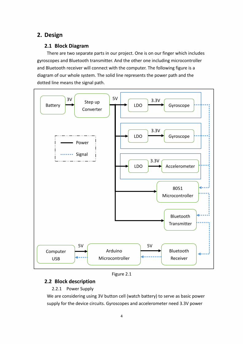
2.1 Block Diagram There are two separate parts in our project. One is on our finger which includes
gyroscopes and Bluetooth transmitter. And the other one including microcontroller
and Bluetooth receiver will connect with the computer. The following figure is a
diagram of our whole system. The solid line represents the power path and the
dotted line means the signal path.
Figure 2.1
2.2 Block description 2.2.1 Power Supply
We are considering using 3V button cell (watch battery) to serve as basic power
supply for the device circuits. Gyroscopes and accelerometer need 3.3V power
Power
Signal
3.3V
Battery Step up
Converter LDO Gyroscope
LDO Gyroscope
LDO Accelerometer
8051
Microcontroller
Bluetooth
Transmitter
Computer
USB
Arduino
Microcontroller
Bluetooth
Receiver
3V 5V 3.3V
5V 5V
3.3V
5
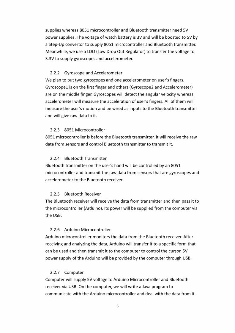
supplies whereas 8051 microcontroller and Bluetooth transmitter need 5V
power supplies. The voltage of watch battery is 3V and will be boosted to 5V by
a Step-Up convertor to supply 8051 microcontroller and Bluetooth transmitter.
Meanwhile, we use a LDO (Low Drop Out Regulator) to transfer the voltage to
3.3V to supply gyroscopes and accelerometer.
2.2.2 Gyroscope and Accelerometer
We plan to put two gyroscopes and one accelerometer on user's fingers.
Gyroscope1 is on the first finger and others (Gyroscope2 and Accelerometer)
are on the middle finger. Gyroscopes will detect the angular velocity whereas
accelerometer will measure the acceleration of user’s fingers. All of them will
measure the user’s motion and be wired as inputs to the Bluetooth transmitter
and will give raw data to it.
2.2.3 8051 Microcontroller
8051 microcontroller is before the Bluetooth transmitter. It will receive the raw
data from sensors and control Bluetooth transmitter to transmit it.
2.2.4 Bluetooth Transmitter
Bluetooth transmitter on the user's hand will be controlled by an 8051
microcontroller and transmit the raw data from sensors that are gyroscopes and
accelerometer to the Bluetooth receiver.
2.2.5 Bluetooth Receiver
The Bluetooth receiver will receive the data from transmitter and then pass it to
the microcontroller (Arduino). Its power will be supplied from the computer via
the USB.
2.2.6 Arduino Microcontroller
Arduino microcontroller monitors the data from the Bluetooth receiver. After
receiving and analyzing the data, Arduino will transfer it to a specific form that
can be used and then transmit it to the computer to control the cursor. 5V
power supply of the Arduino will be provided by the computer through USB.
2.2.7 Computer
Computer will supply 5V voltage to Arduino Microcontroller and Bluetooth
receiver via USB. On the computer, we will write a Java program to
communicate with the Arduino microcontroller and deal with the data from it.
6
The Arduino IDE itself is written in Java, and it can communicate to the serial
port via the RXTX Java library. That library is very similar to the Java
Communications API extension. After getting the data, the Java program will
control the cursor according to the data.
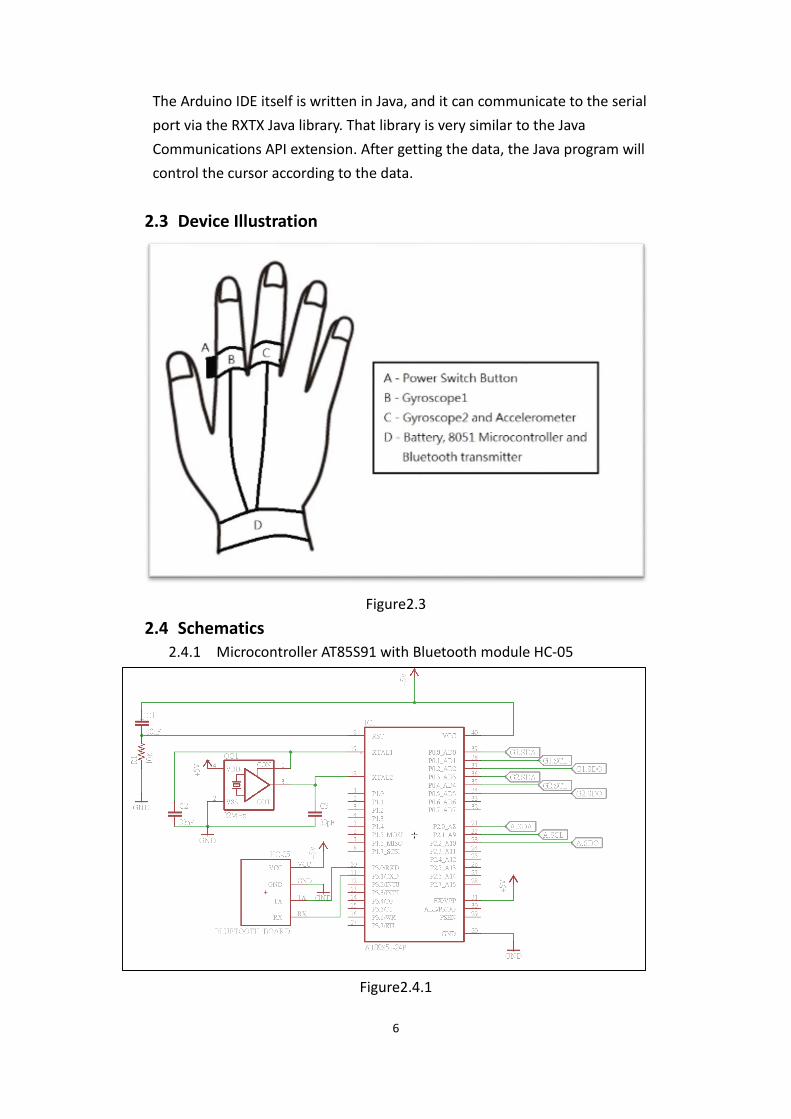
2.3 Device Illustration
Figure2.3
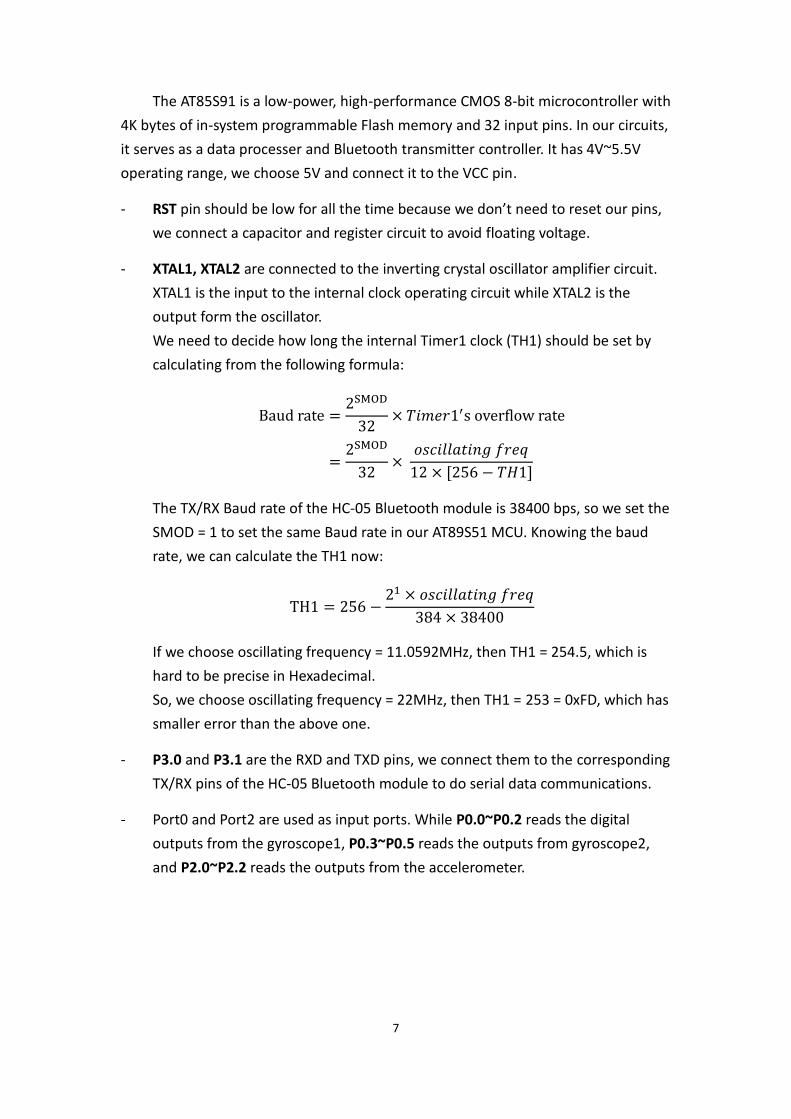
2.4 Schematics 2.4.1 Microcontroller AT85S91 with Bluetooth module HC-05
Figure2.4.1
7
The AT85S91 is a low-power, high-performance CMOS 8-bit microcontroller with
4K bytes of in-system programmable Flash memory and 32 input pins. In our circuits,
it serves as a data processer and Bluetooth transmitter controller. It has 4V~5.5V
operating range, we choose 5V and connect it to the VCC pin.
- RST pin should be low for all the time because we don’t need to reset our pins,
we connect a capacitor and register circuit to avoid floating voltage.
- XTAL1, XTAL2 are connected to the inverting crystal oscillator amplifier circuit.
XTAL1 is the input to the internal clock operating circuit while XTAL2 is the
output form the oscillator.
We need to decide how long the internal Timer1 clock (TH1) should be set by
calculating from the following formula:
Baud rate =2SMOD
32× 𝑇𝑖𝑚𝑒𝑟1′s overflow rate
=2SMOD
32×
𝑜𝑠𝑐𝑖𝑙𝑙𝑎𝑡𝑖𝑛𝑔 𝑓𝑟𝑒𝑞
12 × [256 − 𝑇𝐻1]
The TX/RX Baud rate of the HC-05 Bluetooth module is 38400 bps, so we set the
SMOD = 1 to set the same Baud rate in our AT89S51 MCU. Knowing the baud
rate, we can calculate the TH1 now:
TH1 = 256 −21 × 𝑜𝑠𝑐𝑖𝑙𝑙𝑎𝑡𝑖𝑛𝑔 𝑓𝑟𝑒𝑞
384 × 38400
If we choose oscillating frequency = 11.0592MHz, then TH1 = 254.5, which is
hard to be precise in Hexadecimal.
So, we choose oscillating frequency = 22MHz, then TH1 = 253 = 0xFD, which has
smaller error than the above one.
- P3.0 and P3.1 are the RXD and TXD pins, we connect them to the corresponding
TX/RX pins of the HC-05 Bluetooth module to do serial data communications.
- Port0 and Port2 are used as input ports. While P0.0~P0.2 reads the digital
outputs from the gyroscope1, P0.3~P0.5 reads the outputs from gyroscope2,
and P2.0~P2.2 reads the outputs from the accelerometer.

8
2.4.2 Step up converter
Figure2.4.2
L6920D is a high efficiency boost converter which accept the input voltage
range from 0.6 to 5.5V. We want to use CR2032 Lithium coin cell battery which
provide 3V output voltage. To fit the operating voltage of microcontroller and
Bluetooth transmitter, we use this converter to make 5V output voltage.
- Lx: Connect with input inductor and battery voltage, the recommended
value of input inductor is form 5uF to 40uF. Small inductor have smaller
size and fast transient response but the output ripple would be bigger. In
our project, we need to make everything smaller so we just choose 10uH.
- LBI: Low battery voltage detection. The input voltage will compare the
build-in bandgap voltage (1.23V), LBO_ would be high if the input voltage
is smaller than 1.23. Actually, our battery would provide 3.2V at the
beginning and drop to about 2.5V when it is running out. If the battery
voltage become smaller than 2.7V, we want to light a LED and remind the
user to change the battery. So the ratio of R1 and R2 would be:
R1
R2=
2.7 − 1.23
1.23= 1.195
We just choose R1 = 1.2MΩ and R2 = 1MΩ
- Vref: The build-in band gap voltage. The value is about 1.23V. We just
connect a 100nF capacitor for filtering high frequency noise.
- F.B.: L6920D can adjust the output voltage to be 3.3V or 5V by the
feedback controlling. We just connect it to GND to generate the 5V output
voltage. We select a big R4 (1M) to minimize consumption.
9
- SHDN_: Shut down pin. When it is lower than 0.2V, L6920D would be
disable. We use a switch to control the power of the device.
- LBO_: When low battery voltage been detected, LBO_ goes high and we
can connect with LED to make a warning signal.
- Vout: The output voltage would be 5V with very small ripple. The
recommended range of inductor is from 10uF to 100uF. If we want to
improve the conversion efficiency, low ESR capacitor is needed. We just
choose Panasonic EEFCDJ470R, which is 47uF with 18mohm ESR.
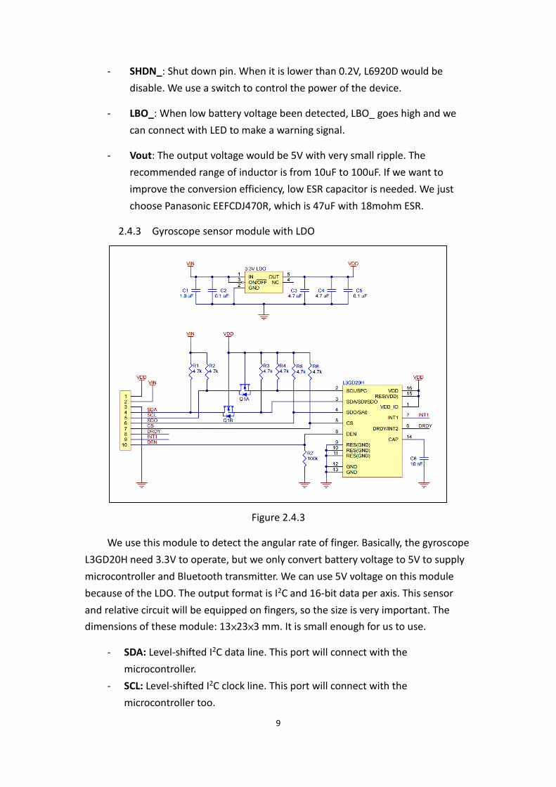
2.4.3 Gyroscope sensor module with LDO
Figure 2.4.3
We use this module to detect the angular rate of finger. Basically, the gyroscope
L3GD20H need 3.3V to operate, but we only convert battery voltage to 5V to supply
microcontroller and Bluetooth transmitter. We can use 5V voltage on this module
because of the LDO. The output format is I2C and 16-bit data per axis. This sensor
and relative circuit will be equipped on fingers, so the size is very important. The
dimensions of these module: 13×23×3 mm. It is small enough for us to use.
- SDA: Level-shifted I2C data line. This port will connect with the
microcontroller.
- SCL: Level-shifted I2C clock line. This port will connect with the
microcontroller too.
10
- CS: This port can adjust the communication format between I2C and SPI. We
use only I2C to transmit data, so we will pull up to VDD.
- SDO: 3.3-logic-level input to determine I2C slave address. Also connect to
microcontroller.
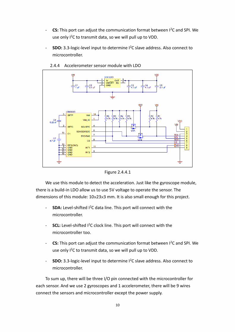
2.4.4 Accelerometer sensor module with LDO
Figure 2.4.4.1
We use this module to detect the acceleration. Just like the gyroscope module,
there is a build-in LDO allow us to use 5V voltage to operate the sensor. The
dimensions of this module: 10×23×3 mm. It is also small enough for this project.
- SDA: Level-shifted I2C data line. This port will connect with the
microcontroller.
- SCL: Level-shifted I2C clock line. This port will connect with the
microcontroller too.
- CS: This port can adjust the communication format between I2C and SPI. We
use only I2C to transmit data, so we will pull up to VDD.
- SDO: 3.3-logic-level input to determine I2C slave address. Also connect to
microcontroller.
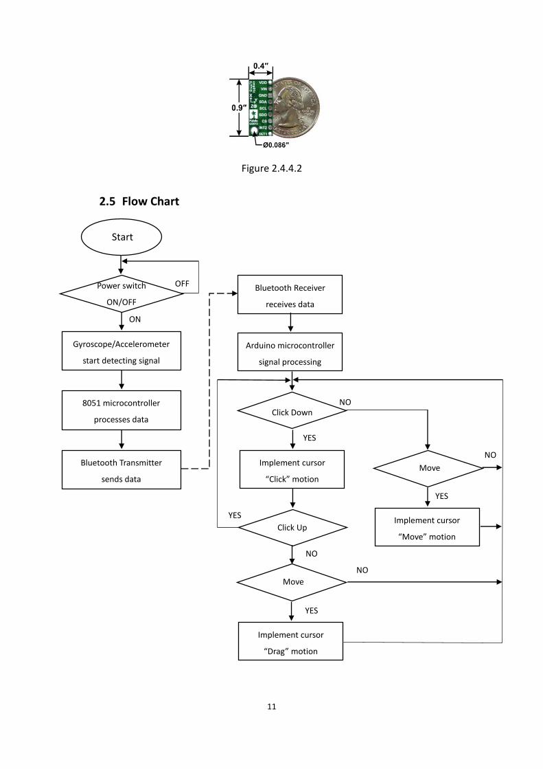
To sum up, there will be three I/O pin connected with the microcontroller for
each sensor. And we use 2 gyroscopes and 1 accelerometer, there will be 9 wires
connect the sensors and microcontroller except the power supply.
11
Figure 2.4.4.2
2.5 Flow Chart
Implement cursor
“Move” motion
Bluetooth Receiver
receives data
Arduino microcontroller
signal processing
YES
Click Down NO
Implement cursor
“Click” motion
8051 microcontroller
processes data
Start
Gyroscope/Accelerometer
start detecting signal
ON
Power switch
ON/OFF
OFF
Bluetooth Transmitter
sends data
YES
Click Up
NO
Implement cursor
“Drag” motion
Move
YES
NO
YES
NO
Move
12
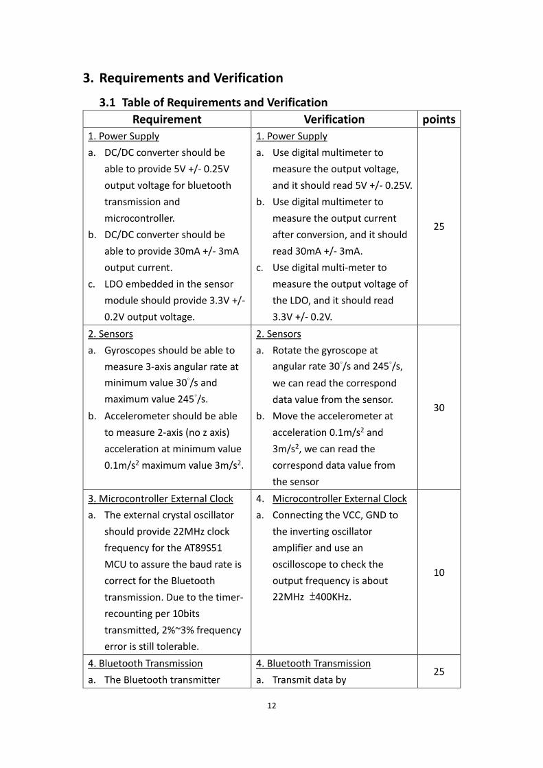
3. Requirements and Verification
3.1 Table of Requirements and Verification
Requirement Verification points
1. Power Supply
a. DC/DC converter should be
able to provide 5V +/- 0.25V
output voltage for bluetooth
transmission and
microcontroller.
b. DC/DC converter should be
able to provide 30mA +/- 3mA
output current.
c. LDO embedded in the sensor
module should provide 3.3V +/-
0.2V output voltage.
1. Power Supply
a. Use digital multimeter to
measure the output voltage,
and it should read 5V +/- 0.25V.
b. Use digital multimeter to
measure the output current
after conversion, and it should
read 30mA +/- 3mA.
c. Use digital multi-meter to
measure the output voltage of
the LDO, and it should read
3.3V +/- 0.2V.
25
2. Sensors
a. Gyroscopes should be able to
measure 3-axis angular rate at
minimum value 30°/s and
maximum value 245°/s.
b. Accelerometer should be able
to measure 2-axis (no z axis)
acceleration at minimum value
0.1m/s2 maximum value 3m/s2.
2. Sensors
a. Rotate the gyroscope at
angular rate 30°/s and 245°/s,
we can read the correspond
data value from the sensor.
b. Move the accelerometer at
acceleration 0.1m/s2 and
3m/s2, we can read the
correspond data value from
the sensor
30
3. Microcontroller External Clock
a. The external crystal oscillator
should provide 22MHz clock
frequency for the AT89S51
MCU to assure the baud rate is
correct for the Bluetooth
transmission. Due to the timer-
recounting per 10bits
transmitted, 2%~3% frequency
error is still tolerable.
4. Microcontroller External Clock
a. Connecting the VCC, GND to
the inverting oscillator
amplifier and use an
oscilloscope to check the
output frequency is about
22MHz ±400KHz.
10
4. Bluetooth Transmission
a. The Bluetooth transmitter
4. Bluetooth Transmission
a. Transmit data by 25

13
should catch the data and
transmit it to the
microcontroller in baud rate
38400 (bps).
b. The Bluetooth transmitter
should be able to transmit data
within 10 meters.
microcontroller to Bluetooth
receiver and transmit it back to
controller. We should receive
and transmit 38400 bits per
second.
b. Take the transmitter 10 meters
away and check whether the
receiver could catch the data.
5. Driver
a. Driver on computer should
catch the specific signals and
operate the cursor properly.
5. Driver
a. Transmit data to the computer
by microcontroller and observe
the movement of the cursor.
10
3.2 Tolerance Analysis
3.2.1 Power Analysis
The capacity of our battery is 220mAh. To operate all the sensor and
microcontroller, it need about 30mA. We can use a battery for about 7.3 hours. It
is an acceptable value but we could increase the battery live by using one more
battery. In the ideal condition, we could use our device for about 14.6 hours. If
the current goes 30% higher than we expect, we can still use the device for 11.2
hours.
3.2.2 Bluetooth transmission distance
One of the features of our project is wireless. Therefore, the distance of
Bluetooth transmission is very important.
According to the datasheet, the Bluetooth receiver has typically -80dBm
sensitivity and up to +0dBm RF transmit power. And as we know that Free-space
path loss formula is
FSPL(dB) = 20 log10(𝑑) + 20 log10(𝑓) − 27.55
where
d is our distance between the transmitter and receiver in meter, and
f is the signal’s frequency in MHz which is 2400MHz
thus
80 = 20 log10(𝑑) + 20 log10(2400) − 27.55
d ≈ 100(m)
That means we can use this mouse in 100 meters.
14
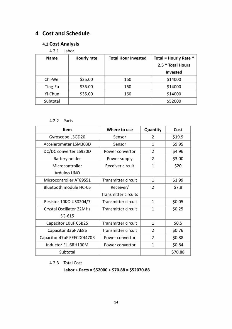
4 Cost and Schedule
4.2 Cost Analysis
4.2.1 Labor
Name Hourly rate Total Hour Invested Total = Hourly Rate *
2.5 * Total Hours
Invested
Chi-Wei $35.00 160 $14000
Ting-Fu $35.00 160 $14000
Yi-Chun $35.00 160 $14000
Subtotal $52000
4.2.2 Parts
Item Where to use Quantity Cost
Gyroscope L3GD20 Sensor 2 $19.9
Accelerometer LSM303D Sensor 1 $9.95
DC/DC converter L6920D Power convertor 2 $4.96
Battery holder Power supply 2 $3.00
Microcontroller
Arduino UNO
Receiver circuit 1 $20
Microcontroller AT89S51 Transmitter circuit 1 $1.99
Bluetooth module HC-05 Receiver/
Transmitter circuits
2 $7.8
Resistor 10KΩ US0204/7 Transmitter circuit 1 $0.05
Crystal Oscillator 22MHz
SG-615
Transmitter circuit 1 $0.25
Capacitor 10uF C5B25 Transmitter circuit 1 $0.5
Capacitor 33pF AE86 Transmitter circuit 2 $0.76
Capacitor 47uF EEFCD0J470R Power convertor 2 $0.88
Inductor ELL6RH100M Power convertor 1 $0.84
Subtotal $70.88
4.2.3 Total Cost
Labor + Parts = $52000 + $70.88 = $52070.88
15
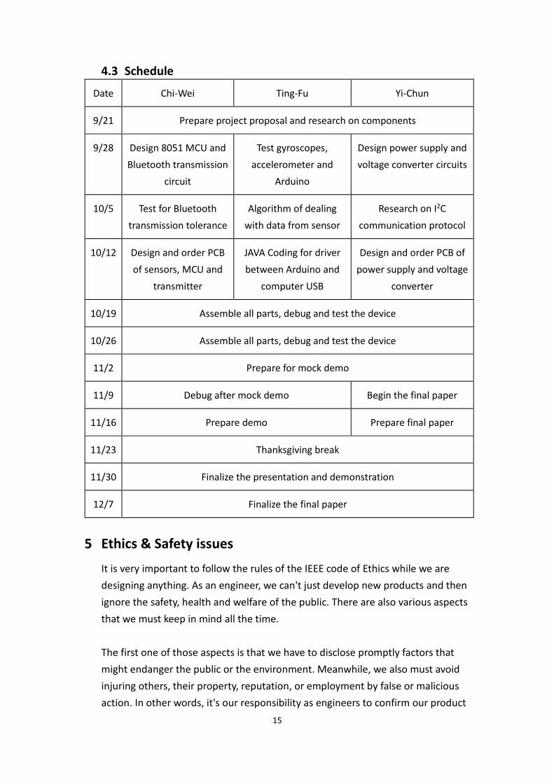
4.3 Schedule
Date Chi-Wei Ting-Fu Yi-Chun
9/21 Prepare project proposal and research on components
9/28 Design 8051 MCU and
Bluetooth transmission
circuit
Test gyroscopes,
accelerometer and
Arduino
Design power supply and
voltage converter circuits
10/5 Test for Bluetooth
transmission tolerance
Algorithm of dealing
with data from sensor
Research on I2C
communication protocol
10/12 Design and order PCB
of sensors, MCU and
transmitter
JAVA Coding for driver
between Arduino and
computer USB
Design and order PCB of
power supply and voltage
converter
10/19 Assemble all parts, debug and test the device
10/26 Assemble all parts, debug and test the device
11/2 Prepare for mock demo
11/9 Debug after mock demo Begin the final paper
11/16 Prepare demo Prepare final paper
11/23 Thanksgiving break
11/30 Finalize the presentation and demonstration
12/7 Finalize the final paper
5 Ethics & Safety issues
It is very important to follow the rules of the IEEE code of Ethics while we are
designing anything. As an engineer, we can't just develop new products and then
ignore the safety, health and welfare of the public. There are also various aspects
that we must keep in mind all the time.
The first one of those aspects is that we have to disclose promptly factors that
might endanger the public or the environment. Meanwhile, we also must avoid
injuring others, their property, reputation, or employment by false or malicious
action. In other words, it's our responsibility as engineers to confirm our product
16
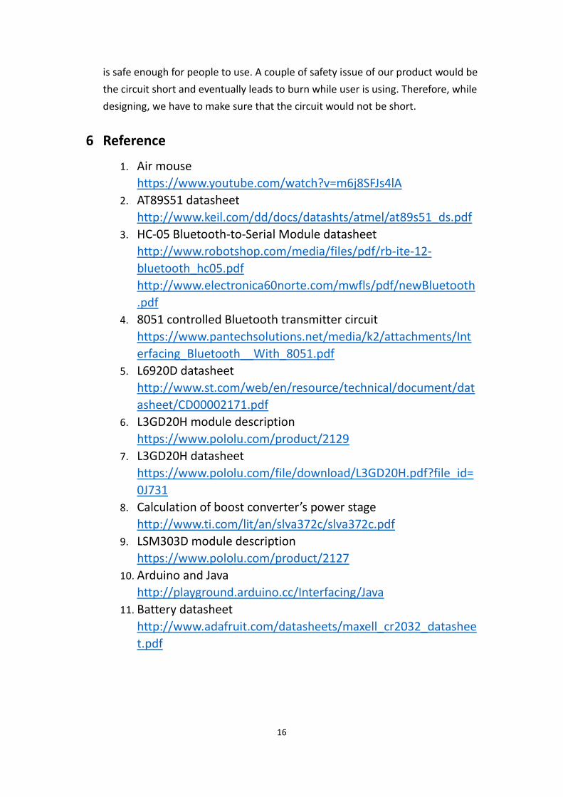
is safe enough for people to use. A couple of safety issue of our product would be
the circuit short and eventually leads to burn while user is using. Therefore, while
designing, we have to make sure that the circuit would not be short.
6 Reference
1. Air mouse
https://www.youtube.com/watch?v=m6j8SFJs4lA
2. AT89S51 datasheet
http://www.keil.com/dd/docs/datashts/atmel/at89s51_ds.pdf
3. HC-05 Bluetooth-to-Serial Module datasheet
http://www.robotshop.com/media/files/pdf/rb-ite-12-
bluetooth_hc05.pdf
http://www.electronica60norte.com/mwfls/pdf/newBluetooth
4. 8051 controlled Bluetooth transmitter circuit
https://www.pantechsolutions.net/media/k2/attachments/Int
erfacing_Bluetooth__With_8051.pdf
5. L6920D datasheet
http://www.st.com/web/en/resource/technical/document/dat
asheet/CD00002171.pdf
6. L3GD20H module description
https://www.pololu.com/product/2129
7. L3GD20H datasheet
https://www.pololu.com/file/download/L3GD20H.pdf?file_id=
0J731
8. Calculation of boost converter’s power stage
http://www.ti.com/lit/an/slva372c/slva372c.pdf
9. LSM303D module description
https://www.pololu.com/product/2127
10. Arduino and Java
http://playground.arduino.cc/Interfacing/Java
11. Battery datasheet
http://www.adafruit.com/datasheets/maxell_cr2032_datashee
t.pdf