finding the forces in a truss
TRANSCRIPT
Finding The Forces In A TrussFinding The Forces In A Truss?V
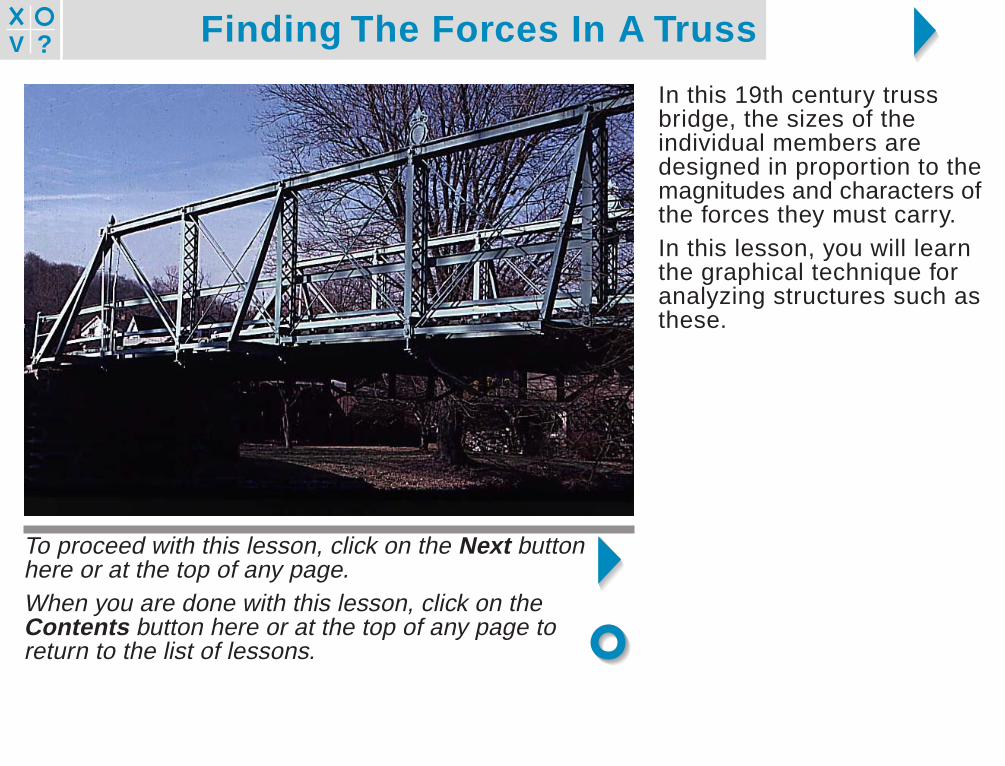
In this 19th century trussbridge, the sizes of theindividual members aredesigned in proportion to themagnitudes and characters ofthe forces they must carry.In this lesson, you will learnthe graphical technique foranalyzing structures such asthese.
To proceed with this lesson, click on the Next buttonhere or at the top of any page.When you are done with this lesson, click on theContents button here or at the top of any page toreturn to the list of lessons.
Finding The Forces In A Truss?V
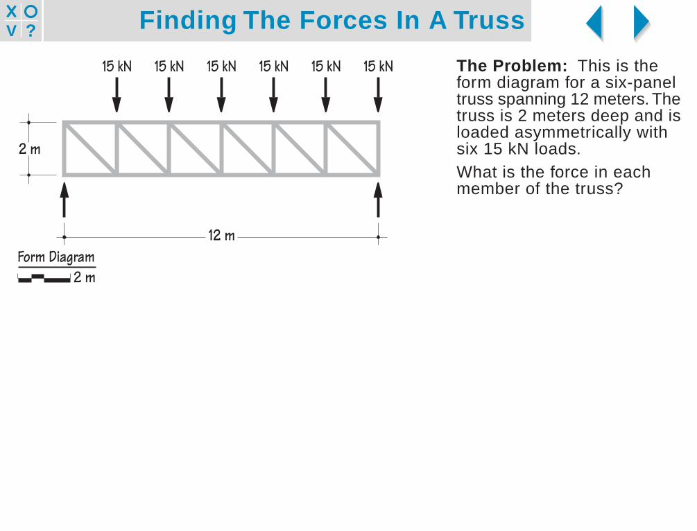
The Problem: This is theform diagram for a six-paneltruss spanning 12 meters. Thetruss is 2 meters deep and isloaded asymmetrically withsix 15 kN loads.What is the force in eachmember of the truss?
15 kN15 kN15 kN15 kN15 kN15 kN
12 m
2 m
Form Diagram2 m
Finding The Forces In A Truss?V
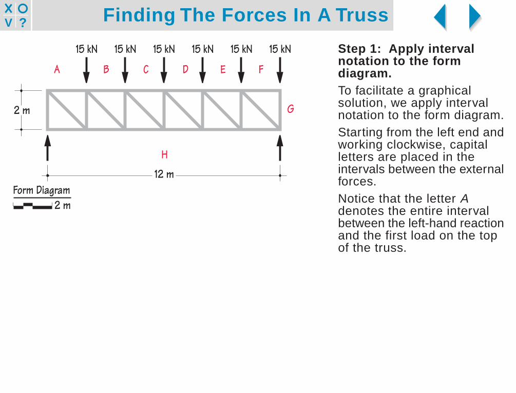
Step 1: Apply intervalnotation to the formdiagram.To facilitate a graphicalsolution, we apply intervalnotation to the form diagram.Starting from the left end andworking clockwise, capitalletters are placed in theintervals between the externalforces.Notice that the letter Adenotes the entire intervalbetween the left-hand reactionand the first load on the topof the truss.
H
G
FEDCBA
15 kN15 kN15 kN15 kN15 kN15 kN
12 m
2 m
Form Diagram2 m

Finding The Forces In A Truss?V
Next, working from left to right,numbers are placed in theinterior spaces of the truss.
H
G
FEDCBA
15 kN15 kN15 kN15 kN15 kN15 kN
12 m
2 m 2 4 6 8 10 121 3 5 7 9 11
Form Diagram2 m
Finding The Forces In A Truss?V
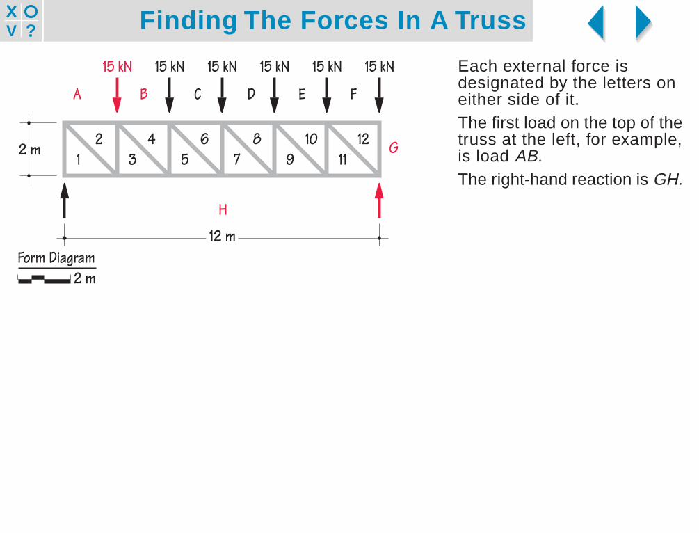
Each external force isdesignated by the letters oneither side of it.The first load on the top of thetruss at the left, for example,is load AB.The right-hand reaction is GH.
H
G
FEDCBA
15 kN15 kN15 kN15 kN15 kN15 kN
12 m
2 m 2 4 6 8 10 121 3 5 7 9 11
Form Diagram2 m

Finding The Forces In A Truss?V
Each member of the truss isalso designated by thecharacters on either side of it.The leftmost vertical member,for example, is A1. Noticeonce again that A designatesthe entire interval from theleft-hand reaction to the firstload on the top of the truss.The rightmost diagonalmember is 11-12.
H
G
FEDCBA
15 kN15 kN15 kN15 kN15 kN15 kN
12 m
2 m 2 4 6 8 10 121 3 5 7 9 11
Form Diagram2 m
Finding The Forces In A Truss?V
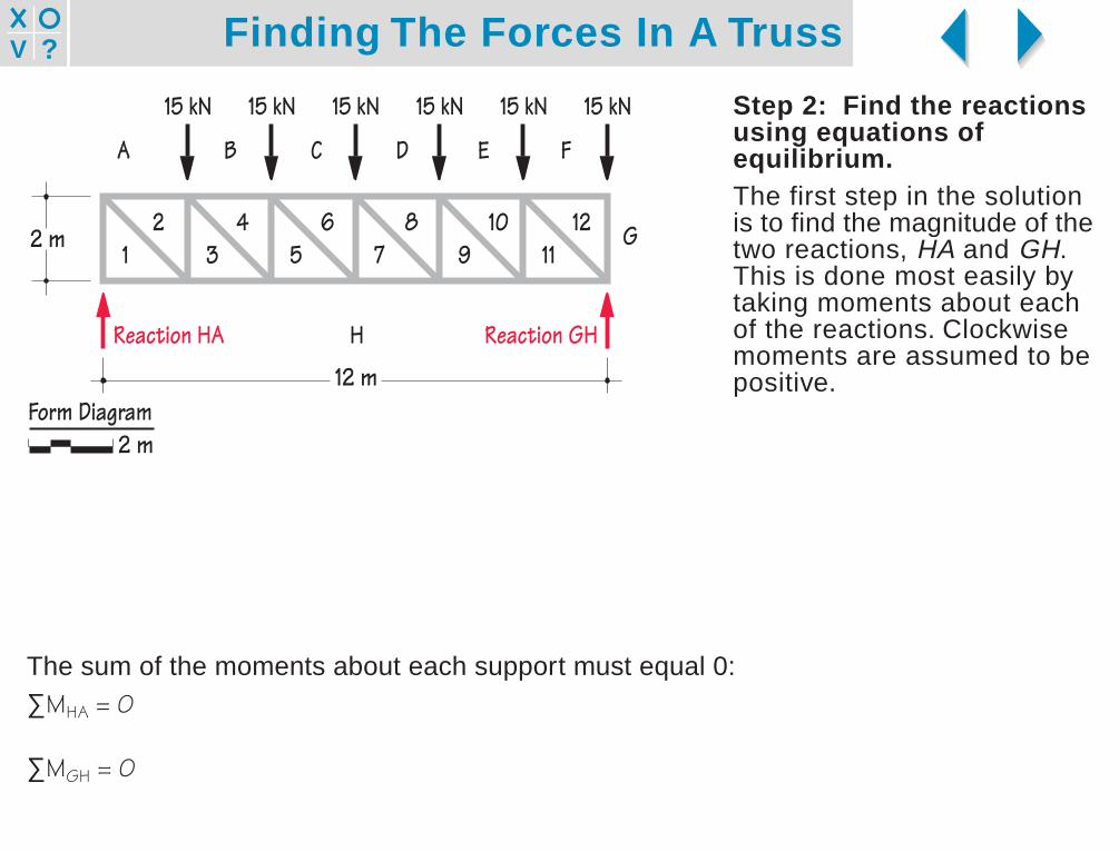
Step 2: Find the reactionsusing equations ofequilibrium.The first step in the solutionis to find the magnitude of thetwo reactions, HA and GH.This is done most easily bytaking moments about eachof the reactions. Clockwisemoments are assumed to bepositive.
The sum of the moments about each support must equal 0:∑MHA = 0
∑MGH = 0
1 3 5 7 9 11
Reaction HA Reaction GHH
G
FEDCBA
15 kN15 kN15 kN15 kN15 kN15 kN
12 m
2 m 2 4 6 8 10 12
Form Diagram2 m
Finding The Forces In A Truss?V
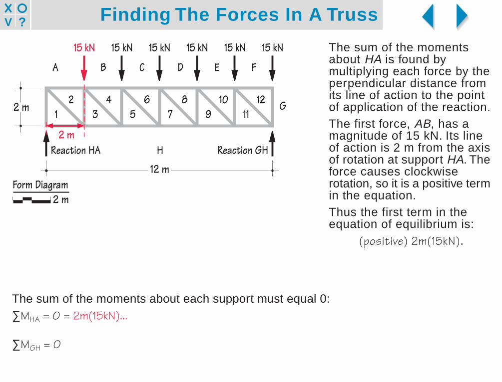
The sum of the momentsabout HA is found bymultiplying each force by theperpendicular distance fromits line of action to the pointof application of the reaction.The first force, AB, has amagnitude of 15 kN. Its lineof action is 2 m from the axisof rotation at support HA. Theforce causes clockwiserotation, so it is a positive termin the equation.Thus the first term in theequation of equilibrium is:
(positive) 2m(15kN).
The sum of the moments about each support must equal 0:∑MHA = 0 = 2m(15kN)...
∑MGH = 0
Reaction HA Reaction GHH
G
FEDCBA
15 kN15 kN15 kN15 kN15 kN15 kN
12 m
2 m
2 m
2 4 6 8 10 121 3 5 7 9 11
Form Diagram2 m

Finding The Forces In A Truss?V
The next force is also 15 kN,but it acts at a perpendiculardistance of 4 m from the pointof application of the reaction.
The sum of the moments about each support must equal 0:∑MHA = 0 = 2m(15kN) + 4m(15kN)...
∑MGH = 0
Reaction HA Reaction GHH
G
FEDCBA
15 kN15 kN15 kN15 kN15 kN15 kN
12 m
2 m
4 m
2 4 6 8 10 121 3 5 7 9 11
Form Diagram2 m
Finding The Forces In A Truss?V
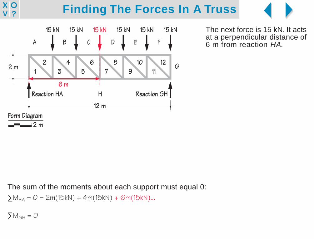
The next force is 15 kN. It actsat a perpendicular distance of6 m from reaction HA.
The sum of the moments about each support must equal 0:∑MHA = 0 = 2m(15kN) + 4m(15kN) + 6m(15kN)...
∑MGH = 0
Reaction HA Reaction GHH
G
FEDCBA
15 kN15 kN15 kN15 kN15 kN15 kN
12 m
2 m
6 m
2 4 6 8 10 121 3 5 7 9 11
Form Diagram2 m
Finding The Forces In A Truss?V
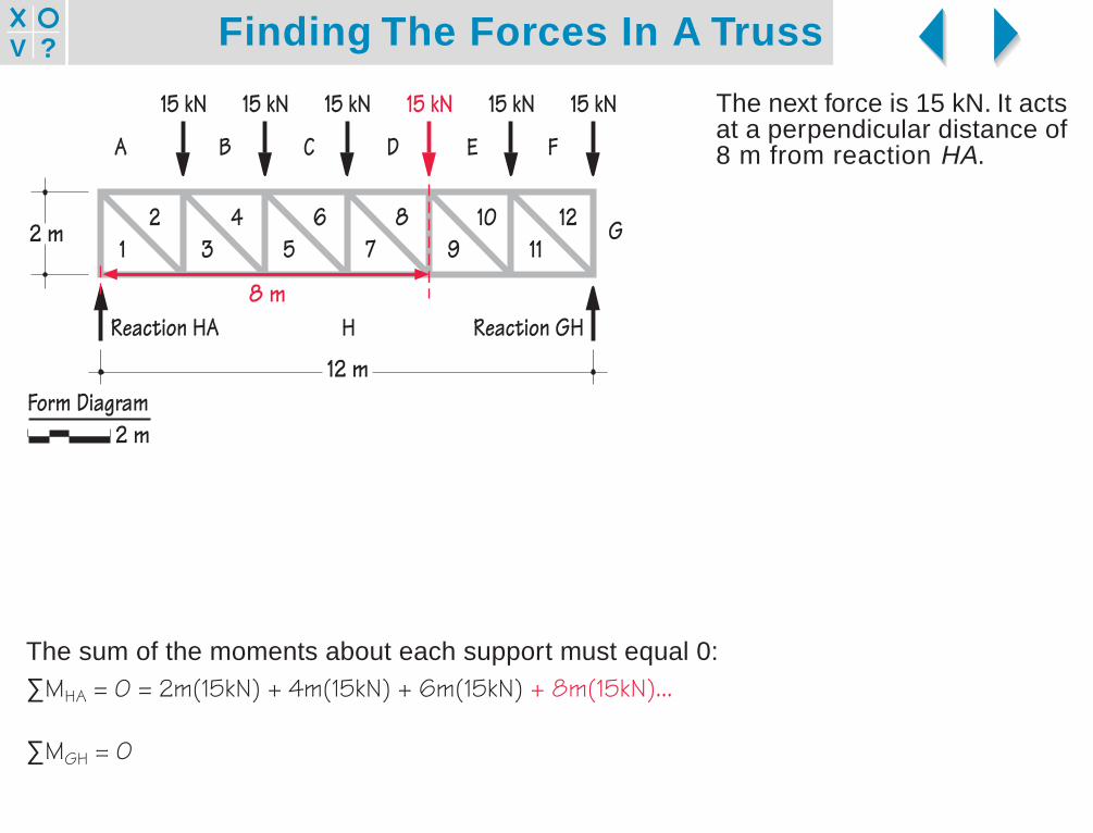
The next force is 15 kN. It actsat a perpendicular distance of8 m from reaction HA.
The sum of the moments about each support must equal 0:∑MHA = 0 = 2m(15kN) + 4m(15kN) + 6m(15kN) + 8m(15kN)...
∑MGH = 0
Reaction HA Reaction GHH
G
FEDCBA
15 kN15 kN15 kN15 kN15 kN15 kN
12 m
2 m
8 m
2 4 6 8 10 121 3 5 7 9 11
Form Diagram2 m
Finding The Forces In A Truss?V
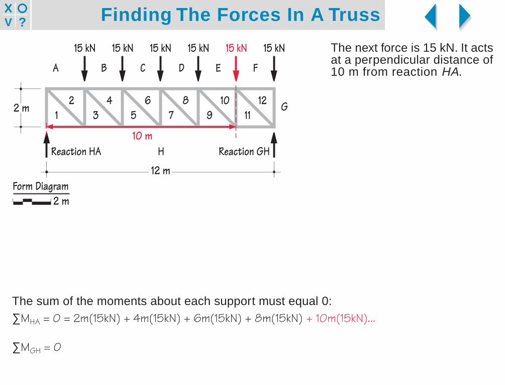
The next force is 15 kN. It actsat a perpendicular distance of10 m from reaction HA.
The sum of the moments about each support must equal 0:∑MHA = 0 = 2m(15kN) + 4m(15kN) + 6m(15kN) + 8m(15kN) + 10m(15kN)...
∑MGH = 0
Reaction HA Reaction GHH
G
FEDCBA
15 kN15 kN15 kN15 kN15 kN15 kN
12 m
2 m
10 m
2 4 6 8 10 121 3 5 7 9 11
Form Diagram2 m

Finding The Forces In A Truss?V
The next force is 15 kN. It actsat a perpendicular distance of12 m from reaction HA.
The sum of the moments about each support must equal 0:∑MHA = 0 = 2m(15kN) + 4m(15kN) + 6m(15kN) + 8m(15kN) + 10m(15kN) + 12m(15kN)...
∑MGH = 0
Reaction HA Reaction GHH
G
FEDCBA
15 kN15 kN15 kN15 kN15 kN15 kN
12 m
2 m
12 m
2 4 6 8 10 121 3 5 7 9 11
Form Diagram2 m

Finding The Forces In A Truss?V
The last force is the unknownreaction GH. The line of actionof GH is 12 m from the axisof rotation. Because GHcauses counterclockwiserotation, it is a negative termin the equation.Notice that reaction HA doesnot appear in the equation.Because its line of actionpasses directly through theaxis of rotation, its distancefrom that point is zero, and ithas no effect on the momentequilibrium.The moment equation is nowcomplete.
The sum of the moments about each support must equal 0:∑MHA = 0 = 2m(15kN) + 4m(15kN) + 6m(15kN) + 8m(15kN) + 10m(15kN) + 12m(15kN) - 12m(GH)
∑MGH = 0
Reaction HA Reaction GHH
G
FEDCBA
15 kN15 kN15 kN15 kN15 kN15 kN
12 m
2 m
12 m
2 4 6 8 10 121 3 5 7 9 11
Form Diagram2 m

Finding The Forces In A Truss?V
We solve the momentequation to find the magnitudeof reaction GH.
The sum of the moments about each support must equal 0:∑MHA = 0 = 2m(15kN) + 4m(15kN) + 6m(15kN) + 8m(15kN) + 10m(15kN) + 12m(15kN) - 12m(GH) GH = 52.5 kN∑MGH = 0
Reaction HA Reaction GHH
G
FEDCBA
15 kN15 kN15 kN15 kN15 kN15 kN
12 m
2 m 2 4 6 8 10 121 3 5 7 9 11
52.5 kN
Form Diagram2 m

Finding The Forces In A Truss?V
Following the sameprocedure, but takingmoments about the reactionGH, we solve for HA.
The sum of the moments about each support must equal 0:∑MHA = 0 = 2m(15kN) + 4m(15kN) + 6m(15kN) + 8m(15kN) + 10m(15kN) + 12m(15kN) - 12m(GH) GH = 52.5 kN∑MGH = 0 = 12m(HA) - 10m(15kN) - 8m(15kN) - 6m(15kN) - 4m(15kN) - 2m(15kN) - 0m(15kN) HA = 37.5 kN
Reaction HA Reaction GHH
G
FEDCBA
15 kN15 kN15 kN15 kN15 kN15 kN
12 m
2 m
37.5 kN
2 4 6 8 10 121 3 5 7 9 11
52.5 kN
Form Diagram2 m

Finding The Forces In A Truss?V
As a check on the accuracyof our work, we sum the forcesin the vertical direction todetermine whether they addup to zero:∑FV = 6(15kN) - 52.5kN - 37.5kN∑FV = 0 OK
It is always worth checkingthe accuracy of the reactionsyou have calculated beforeperforming any furtheranalysis. If the reactions arenot correct, the remainder ofthe analysis will be wrong andyou will have to start over fromthe beginning.
Reaction HA Reaction GHH
G
FEDCBA
15 kN15 kN15 kN15 kN15 kN15 kN
12 m
2 m
37.5 kN
2 4 6 8 10 121 3 5 7 9 11
52.5 kN
Form Diagram2 m

Finding The Forces In A Truss?V
Step 3: Construct the LoadLine.The Load Line is a graphicalsummation of the loads actingon the structure. We adopt aconvenient scale of length-to-force, one that will allow theLoad Line to fit comfortablyon the page.Because all the externalforces acting on the truss arevertical, the Load Line will bevertical as well.
H
G
FEDCBA
15 kN15 kN15 kN15 kN15 kN15 kN
12 m
2 m
37.5 kN
2 4 6 8 10 121 3 5 7 9 11
52.5 kN
20 kNLoad Line
Form Diagram2 m

Finding The Forces In A Truss?V
The external forces on theForm Diagram are plottedfrom left to right onto the LoadLine.Each segment on the LoadLine is labeled at its ends withlower case letters. Notice howintervals on the Form Diagramcorrespond to points on theLoad Line.The first force, AB, actsdownward with a magnitudeof 15 kN. Thus we plot avertical segment on the LoadLine, scaled to 15 kN inlength.Since this force actsdownward as we moveclockwise from A to B on theForm Diagram, b is placedbelow a on the Load Line.
H
G
FEDCBA
15 kN15 kN15 kN15 kN15 kN15 kN
12 m
2 m
37.5 kN
2 4 6 8 10 121 3 5 7 9 11
52.5 kN
20 kNLoad Line
Form Diagram2 m
a
b
0kN20
4060
80100
Finding The Forces In A Truss?V
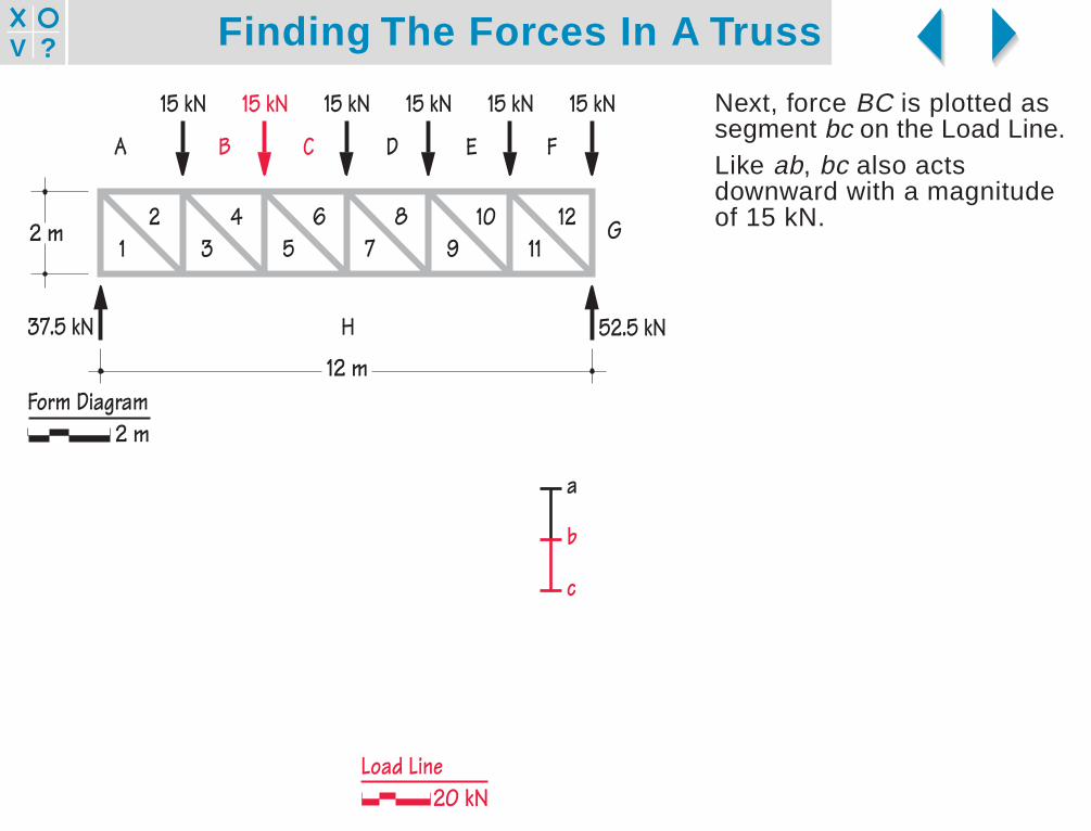
Next, force BC is plotted assegment bc on the Load Line.Like ab, bc also actsdownward with a magnitudeof 15 kN.
H
G
FEDCBA
15 kN15 kN15 kN15 kN15 kN15 kN
12 m
2 m
37.5 kN
2 4 6 8 10 121 3 5 7 9 11
52.5 kN
20 kNLoad Line
Form Diagram2 m
a
b
c
Finding The Forces In A Truss?V
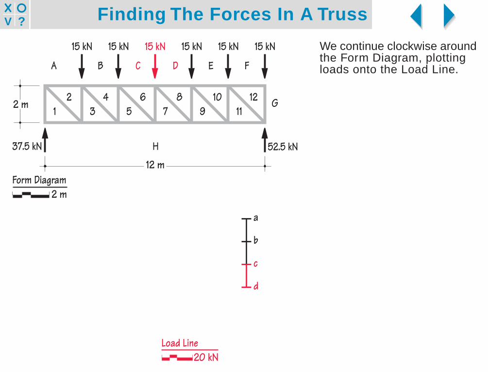
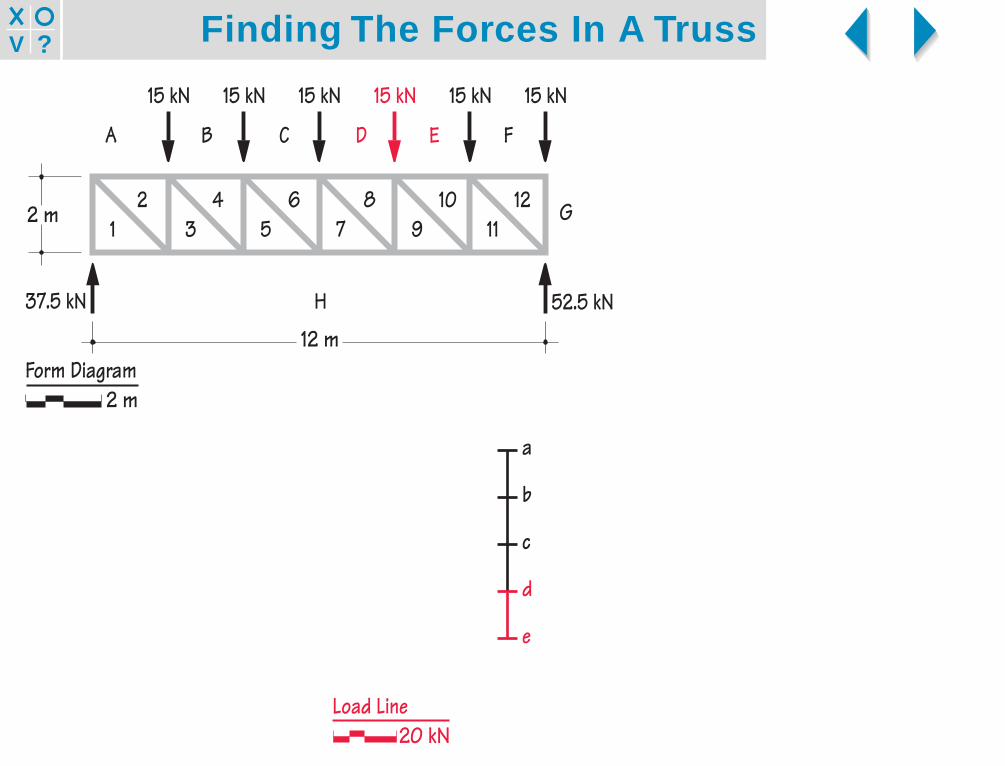
We continue clockwise aroundthe Form Diagram, plottingloads onto the Load Line.
H
G
FEDCBA
15 kN15 kN15 kN15 kN15 kN15 kN
12 m
2 m
37.5 kN
2 4 6 8 10 121 3 5 7 9 11
52.5 kN
20 kNLoad Line
Form Diagram2 m
a
b
c
d
Finding The Forces In A Truss?V
H
G
FEDCBA
15 kN15 kN15 kN15 kN15 kN15 kN
12 m
2 m
37.5 kN
2 4 6 8 10 121 3 5 7 9 11
52.5 kN
20 kNLoad Line
Form Diagram2 m
a
b
c
d
e
Finding The Forces In A Truss?V
H
G
FEDCBA
15 kN15 kN15 kN15 kN15 kN15 kN
12 m
2 m
37.5 kN
2 4 6 8 10 121 3 5 7 9 11
52.5 kN
20 kNLoad Line
Form Diagram2 m
a
b
c
d
e
f

Finding The Forces In A Truss?V
H
G
FEDCBA
15 kN15 kN15 kN15 kN15 kN15 kN
12 m
2 m
37.5 kN
2 4 6 8 10 121 3 5 7 9 11
52.5 kN
20 kNLoad Line
Form Diagram2 m
a
b
c
d
e
f
g

Finding The Forces In A Truss?V
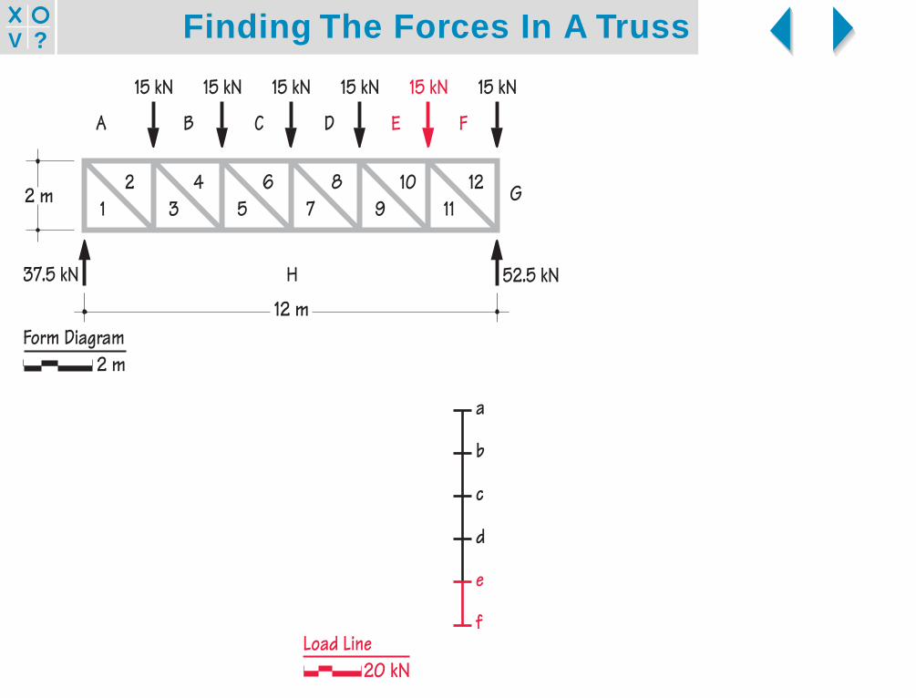
As we move clockwise fromG to H on the Form Diagram,the reaction force actsupward, so h is located aboveg on the Load Line.gh is scaled to 52.5 kN.
2 4 6 8 10 121 3 5 7 9 11
H
G
FEDCBA
15 kN15 kN15 kN15 kN15 kN15 kN
12 m
2 m
37.5 kN 52.5 kN
20 kNLoad Line
Form Diagram2 m
a
b
c
d
e
f
g
h0kN20
4060
Finding The Forces In A Truss?V
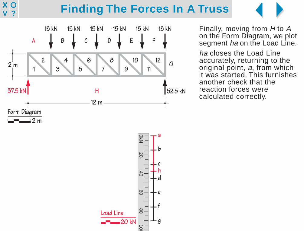
Finally, moving from H to Aon the Form Diagram, we plotsegment ha on the Load Line.ha closes the Load Lineaccurately, returning to theoriginal point, a, from whichit was started. This furnishesanother check that thereaction forces werecalculated correctly.
H
G
FEDCBA
15 kN15 kN15 kN15 kN15 kN15 kN
12 m
2 m
37.5 kN
2 4 6 8 10 121 3 5 7 9 11
52.5 kN
20 kNLoad Line
Form Diagram2 m
a
b
c
d
e
f
g
h0kN
2040
6080
100

Finding The Forces In A Truss?V
Step 4: Find the forces inthe truss members.To find the member forces, weconstruct pairs of intersectinglines off the Load Line to forma Force Polygon. We workfrom left to right.Each pair of member forcesshares the same number,beginning at the left, with 1.Thus we look first on the FormDiagram for two memberswhose names include thenumber 1. These are A1 andH1.
H
G
FEDCBA
15 kN15 kN15 kN15 kN15 kN15 kN
12 m
2 m
37.5 kN
2 4 6 8 10 121 3 5 7 9 11
Member H1Member A1 52.5 kN
a
b
c
d
e
f
g
h
Force Polygon20 kN
Form Diagram2 m

Finding The Forces In A Truss?V
Member A1 is vertical. Theforce in member A1 isrepresented on the ForcePolygon by a vertical linethrough point a, which liesalong the Load Line.Since we do not yet know thelocation of point 1, we knowthe direction of this line, butnot yet its length.
H
G
FEDCBA
15 kN15 kN15 kN15 kN15 kN15 kN
12 m
2 m
37.5 kN
2 4 6 8 10 121 3 5 7 9 11
Member H1Member A1 52.5 kN
a
b
c
d
e
f
g
h
Force Polygon20 kN
Line a1 of known directionbut unknown length(shown in red)
Form Diagram2 m

Finding The Forces In A Truss?V
Member H1 is horizontal. Theforce in member H1 isrepresented on the ForcePolygon by a horizontal linethrough point h.The two lines that we haveconstructed parallel tomembers A1 and H1 intersectat point h. The intersection ofthese two lines is also point 1.Therefore h and 1 are thesame point.
H
G
FEDCBA
15 kN15 kN15 kN15 kN15 kN15 kN
12 m
2 m
37.5 kN
2 4 6 8 10 121 3 5 7 9 11
Member H1Member A1 52.5 kN
a
b
c
d
e
f
g
h
Point 1
Force Polygon20 kN
Form Diagram2 m
Finding The Forces In A Truss?V
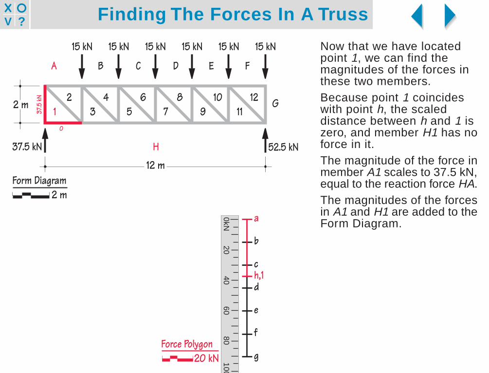
Now that we have locatedpoint 1, we can find themagnitudes of the forces inthese two members.Because point 1 coincideswith point h, the scaleddistance between h and 1 iszero, and member H1 has noforce in it.The magnitude of the force inmember A1 scales to 37.5 kN,equal to the reaction force HA.The magnitudes of the forcesin A1 and H1 are added to theForm Diagram.
H
G
FEDCBA
15 kN15 kN15 kN15 kN15 kN15 kN
12 m
2 m
37.5 kN
137.5
kN
0
52.5 kN
2 4 6 8 10 123 5 7 9 11
a
b
c
d
e
f
g
h,10kN
2040
6080
100
Force Polygon20 kN
Form Diagram2 m

Finding The Forces In A Truss?V
Next we seek the location ofpoint 2.The truss members whosenames include the number 2are A2 and 1-2. A2 ishorizontal, and 1-2 slopesdown to the right at 45o.Force a2 is represented onthe Force Polygon by ahorizontal line through pointa. Force 1-2 is represented bya line through point 1 parallelto truss member 1-2.The intersection of these twolines is point 2.
H
G
FEDCBA
15 kN15 kN15 kN15 kN15 kN15 kN
12 m
2 m
37.5 kN
37.5
kN
0
2 4 6 8 10 123 5 7 9 111
52.5 kN
a
b
c
d
e
f
g
h,1
Point 2
Force Polygon20 kN
Form Diagram2 m
Finding The Forces In A Truss?V
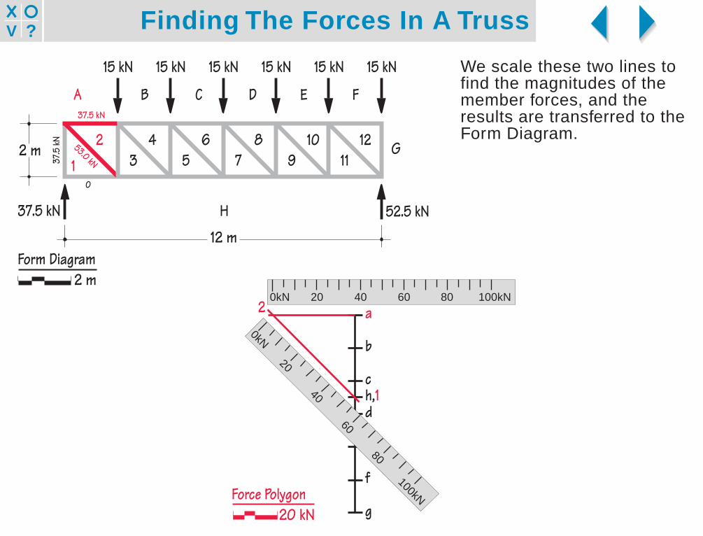
We scale these two lines tofind the magnitudes of themember forces, and theresults are transferred to theForm Diagram.
53.0 kN
H
G
FEDCBA
15 kN15 kN15 kN15 kN15 kN15 kN
12 m
2 m1
37.5 kN
37.5
kN
37.5 kN
0
2 4 6 8 10 123 5 7 9 11
52.5 kN
0kN 20 40 60 80 100kN
a
b
c
d
e
f
g
h,1
20kN
20
40
60
80
100kNForce Polygon20 kN
Form Diagram2 m

Finding The Forces In A Truss?V
In similar fashion, we locatepoint 3 on the Force Polygonby drawing a line parallel tomember 2-3 through point 2,and a line parallel to memberH3 through h.The intersection of these twolines is point 3. We scalethese lines to find themagnitudes of the forces inthe two members that theyrepresent.
2 4 6 8 10 123 5 7 9 11
37.5
kN
53.0 kN
2
H
G
FEDCBA
15 kN15 kN15 kN15 kN15 kN15 kN
12 m
2 m1
37.5 kN
37.5
kN
37.5 kN
0 37.5 kN
52.5 kN
a
b
c
d
e
f
g
h,1
2
3
Force Polygon20 kN
Form Diagram2 m

Finding The Forces In A Truss?V
Point 4 on the Force Polygonlies at the intersection of linesparallel to members B4 and3-4, the truss members whosenames both include thenumber 4.Notice how we are finding ourway through the truss byfollowing the numbers insequence.
2 4 6 8 10 123 5 7 9 11
37.5
kN
53.0 kN
31.8 kN
H
G
FEDCBA
15 kN15 kN15 kN15 kN15 kN15 kN
12 m
2 m1
37.5 kN
37.5
kN
37.5 kN 60.0 kN
0 37.5 kN
2 4
3
52.5 kN
a
b
c
d
e
f
g
h,1
2
4
3
Force Polygon20 kN
Form Diagram2 m

Finding The Forces In A Truss?V
2 4 6 8 10 123 5 7 9 11
2 4
37.5
kN
22.5
kN
53.0 kN
31.8 kN
H
G
FEDCBA
15 kN15 kN15 kN15 kN15 kN15 kN
12 m
2 m1 3
37.5 kN
37.5
kN
37.5 kN 60.0 kN
0 37.5 kN 60.0 kN
52.5 kN
a
b
c
d
e
f
g
h,1
2
4
5 3
Force Polygon20 kN
Form Diagram2 m
Finding The Forces In A Truss?V
3 5 7 9 112 4 6 8 10 122 4
37.5
kN
22.5
kN
53.0 kN
31.8 kN10.6 kN
H
G
FEDCBA
15 kN15 kN15 kN15 kN15 kN15 kN
12 m
2 m1 3 5
37.5 kN
37.5
kN
37.5 kN 60.0 kN 67.5 kN
0 37.5 kN 60.0 kN
52.5 kN
a
b
c
d
e
f
g
h,1
2
4
65 3
Force Polygon20 kN
Form Diagram2 m

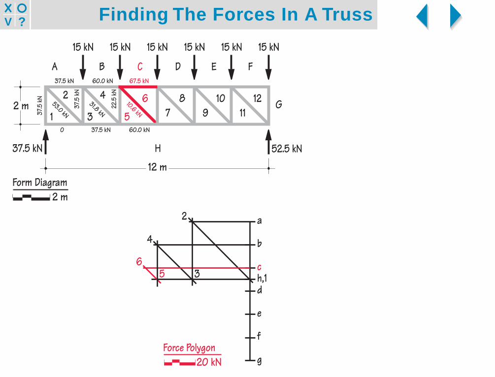
Finding The Forces In A Truss?V
3 5 7 9 112 4 6 8 10 122 4 6
37.5
kN
22.5
kN
7.5 kN
53.0 kN
31.8 kN10.6 kN
H
G
FEDCBA
15 kN15 kN15 kN15 kN15 kN15 kN
12 m
2 m1 3 5
37.5 kN
37.5
kN
37.5 kN 60.0 kN 67.5 kN
0 37.5 kN 60.0 kN 67.5 kN
52.5 kN
a
b
c
d
e
f
g
h,1
2
4
67 5 3
Force Polygon20 kN
Form Diagram2 m
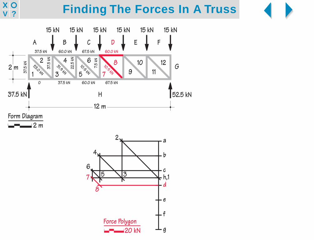
Finding The Forces In A Truss?V
2 4 6
37.5
kN
22.5
kN
7.5 kN
53.0 kN
31.8 kN10.6 kN
10.6 kN
H
G
FEDCBA
15 kN15 kN15 kN15 kN15 kN15 kN
12 m
2 m1 3 5 7
37.5 kN
37.5
kN
37.5 kN 60.0 kN 67.5 kN 60.0 kN
0 37.5 kN 60.0 kN 67.5 kN
52.5 kN
3 5 7 9 112 4 6 8 10 12
a
b
c
d
e
f
g
h,1
2
4
67
8
5 3
Force Polygon20 kN
Form Diagram2 m

Finding The Forces In A Truss?V
Points 5 and 9 share the samelocation.
3 5 7 9 112 4 6 8
37.5
kN
22.5
kN
7.5 kN
7.5 kN
53.0 kN
31.8 kN10.6 kN
10.6 kN
H
G
FEDCBA
15 kN15 kN15 kN15 kN15 kN15 kN
12 m
2 m1 3 5 7
37.5 kN
37.5
kN
37.5 kN 60.0 kN 67.5 kN 60.0 kN
0 37.5 kN 60.0 kN 67.5 kN 60.0 kN
52.5 kN
2 4 6 8 10 12
a
b
c
d
e
f
g
h,1
2
4
67
8
5,9 3
Force Polygon20 kN
Form Diagram2 m

Finding The Forces In A Truss?V
3 5 7 9 112 4 6 8 10 122 4 6 8
3 5 7 9
37.5
kN
22.5
kN
7.5 kN
7.5 kN
53.0 kN
31.8 kN10.6 kN
10.6 kN31.8 kN
H
G
FEDCBA
15 kN15 kN15 kN15 kN15 kN15 kN
12 m
2 m1
37.5 kN
37.5
kN
37.5 kN 60.0 kN 67.5 kN 60.0 kN 37.5 kN
0 37.5 kN 60.0 kN 67.5 kN 60.0 kN
52.5 kN
a
b
c
d
e
f
g
h,1
2
4
67
8
5,9
10
3
Force Polygon20 kN
Form Diagram2 m
Finding The Forces In A Truss?V
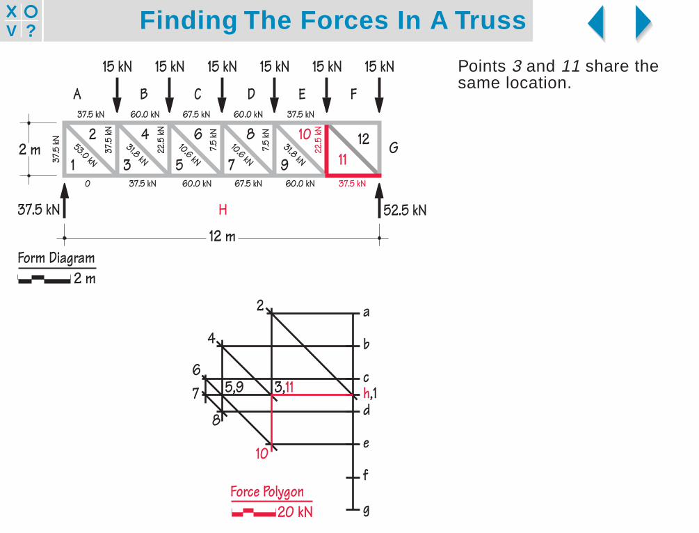
Points 3 and 11 share thesame location.
3 5 7 9 112 4 6 8 10 12
3 5 7 9
2 4 6 8 10
37.5
kN
22.5
kN
7.5 kN
7.5 kN
22.5
kN
53.0 kN
31.8 kN10.6 kN
10.6 kN31.8 kN
H
G
FEDCBA
15 kN15 kN15 kN15 kN15 kN15 kN
12 m
2 m1
37.5 kN
37.5
kN
37.5 kN 60.0 kN 67.5 kN 60.0 kN 37.5 kN
52.5 kN
0 37.5 kN 60.0 kN 67.5 kN 60.0 kN 37.5 kN
a
b
c
d
e
f
g
h,1
2
4
67
8
5,9
10
3,11
Force Polygon20 kN
Form Diagram2 m

Finding The Forces In A Truss?V
Line 11-12 intersects line f12exactly at point f on the LoadLine, so f and 12 share thesame location.This tells us that member F12carries no force.
2 4 6 8 10 123 5 7 9 11
2 4 6 8 10
37.5
kN
22.5
kN
7.5 kN
7.5 kN
22.5
kN
53.0 kN
31.8 kN10.6 kN
10.6 kN31.8 kN
53.0 kN
H
G
FEDCBA
15 kN15 kN15 kN15 kN15 kN15 kN
12 m
2 m1
37.5 kN
37.5
kN
37.5 kN 60.0 kN 67.5 kN 60.0 kN 37.5 kN 0
0 37.5 kN 60.0 kN 67.5 kN 60.0 kN 37.5 kN
52.5 kN
a
b
c
d
e
f,12
g
h,1
2
4
67
8
5,9
10
3,11
Force Polygon20 kN
Form Diagram2 m

Finding The Forces In A Truss?V
Since point g already existson the Force Polygon, plottingthe last force, g12, allows usto verify the accuracy of thegraphic construction.If the Force Polygon wereinaccurately constructed, aline starting from point 12 andplotted parallel to G12 mightnot intersect with the alreadyestablished point g. If thiswere the case, the distanceby which the final segmentmissed the known point couldbe scaled to determinewhether the inaccuracy wassufficiently large to require acomplete redrawing of theForce Polygon.
37.5
kN
22.5
kN
7.5 kN
7.5 kN
22.5
kN
53.0 kN
31.8 kN10.6 kN
10.6 kN31.8 kN
53.0 kN
2 4 6 8 10 12
H
G
FEDCBA
15 kN15 kN15 kN15 kN15 kN15 kN
12 m
2 m1 3 5 7 9 11
37.5 kN
37.5
kN
37.5 kN 60.0 kN 67.5 kN 60.0 kN 37.5 kN 0
0 37.5 kN 60.0 kN 67.5 kN 60.0 kN 37.5 kN
52.5 kN
a
b
c
d
e
f,12
g
h,1
2
4
67
8
5,9
10
3,11
Force Polygon20 kN
Form Diagram2 m

Finding The Forces In A Truss?V
In this case, the ForcePolygon closes accurately,and we can see that g12 isequal in magnitude to the15 kN load directly above it.
37.5
kN
22.5
kN
7.5 kN
7.5 kN
22.5
kN
15.0
kN
53.0 kN
31.8 kN10.6 kN
10.6 kN31.8 kN
53.0 kN
2 4 6 8 10 12
H
G
FEDCBA
15 kN15 kN15 kN15 kN15 kN15 kN
12 m
2 m1 3 5 7 9 11
37.5 kN
37.5
kN
37.5 kN 60.0 kN 67.5 kN 60.0 kN 37.5 kN 0
0 37.5 kN 60.0 kN 67.5 kN 60.0 kN 37.5 kN
52.5 kN
a
b
c
d
e
f,12
g
h,1
2
4
67
8
5,9
10
3,11
Force Polygon20 kN
Form Diagram2 m

Finding The Forces In A Truss?V
Step 5: Find the characterof the member forces.Although we now know themagnitudes of all the memberforces, we do not yet knowtheir characters: tension orcompression.Interval notation helps us todetermine the character ofeach force by using a simpleclockwise convention.
37.5
kN
22.5
kN
7.5 kN
7.5 kN
22.5
kN
15.0
kN
53.0 kN
31.8 kN10.6 kN
10.6 kN31.8 kN
53.0 kN
2 4 6 8 10 12
H
G
FEDCBA
15 kN15 kN15 kN15 kN15 kN15 kN
12 m
2 m1 3 5 7 9 11
37.5 kN
37.5
kN
37.5 kN 60.0 kN 67.5 kN 60.0 kN 37.5 kN 0
0 37.5 kN 60.0 kN 67.5 kN 60.0 kN 37.5 kN
52.5 kN
Force Polygon20 kN
a
b
c
d
e
f,12
g
h,1
2
4
67
8
5,9
10
3,11
Form Diagram2 m

Finding The Forces In A Truss?V
As an example of this,consider the joint under theleftmost 15 kN load.This joint is named by readingthe letters and numbersaround it in any clockwiseorder. We may call itB-4-3-2-A, or 2-A-B-4-3, orany other clockwisesequence.
37.5
kN
22.5
kN
7.5 kN
7.5 kN
22.5
kN
15.0
kN
53.0 kN
31.8 kN10.6 kN
10.6 kN31.8 kN
53.0 kN
2 4 6 8 10 12
H
G
FEDCBA
15 kN15 kN15 kN15 kN15 kN15 kN
12 m
2 m1 3 5 7 9 11
37.5 kN
37.5
kN
37.5 kN 60.0 kN 67.5 kN 60.0 kN 37.5 kN 0
0 37.5 kN 60.0 kN 67.5 kN 60.0 kN 37.5 kN
52.5 kN
a
b
c
d
e
f,12
g
h,1
2
4
67
8
5,9
10
3,11
Force Polygon20 kN
Form Diagram2 m

Finding The Forces In A Truss?V
To find the character of theforce in member B4, we notethat in clockwise order, it mustbe called B4, and not 4B.As we read from b to 4 on theForce Polygon, we are movingfrom right to left. This meansthat on the Form Diagram, theforce in member B4 acts fromright to left, pushing againstjoint B-4-3-2-A. Thus themember is in compression.We indicate this with a “c” onthe Form Diagram.
37.5
kN
22.5
kN
7.5 kN
7.5 kN
22.5
kN
15.0
kN
53.0 kN
31.8 kN10.6 kN
10.6 kN31.8 kN
53.0 kN
2 4 6 8 10 12
H
G
FEDCBA
15 kN15 kN15 kN15 kN15 kN15 kN
12 m
2 m1 3 5 7 9 11
37.5 kN
37.5
kN
37.5 kN 60.0 kN 67.5 kN 60.0 kN 37.5 kN 0
0 37.5 kN 60.0 kN 67.5 kN 60.0 kN 37.5 kN
52.5 kN
c
a
b
c
d
e
f,12
g
h,1
2
4
67
8
5,9
10
3,11
Force Polygon20 kN
Form Diagram2 m
Finding The Forces In A Truss?V
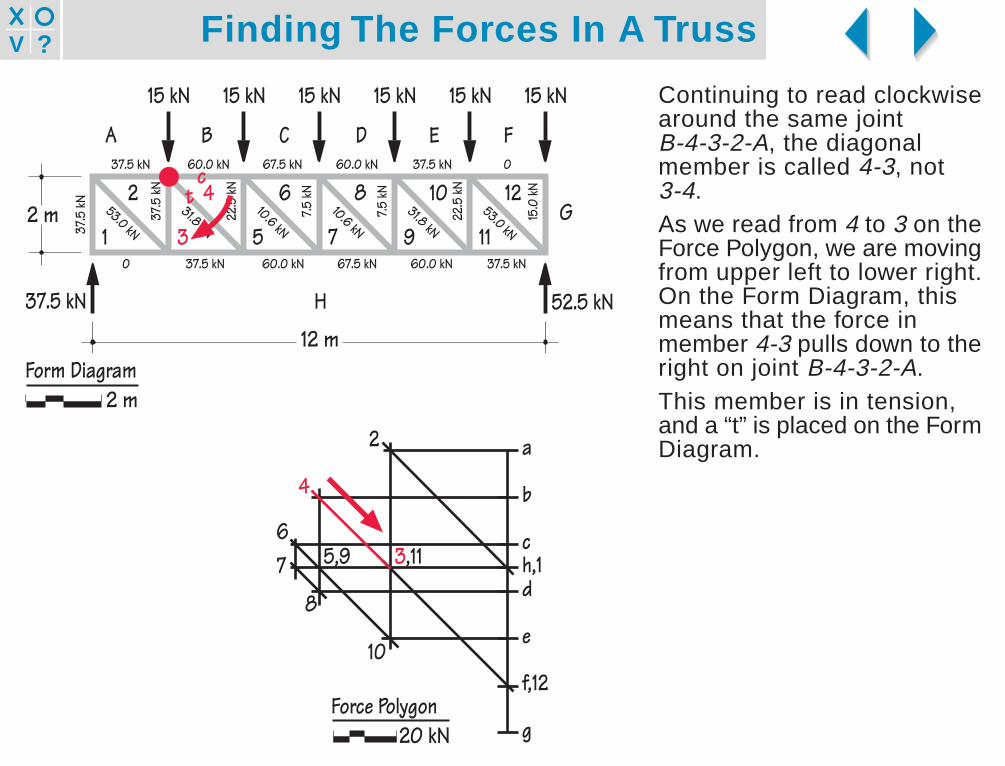
Continuing to read clockwisearound the same jointB-4-3-2-A, the diagonalmember is called 4-3, not3-4.As we read from 4 to 3 on theForce Polygon, we are movingfrom upper left to lower right.On the Form Diagram, thismeans that the force inmember 4-3 pulls down to theright on joint B-4-3-2-A.This member is in tension,and a “t” is placed on the FormDiagram.
37.5
kN
22.5
kN
7.5 kN
7.5 kN
22.5
kN
15.0
kN
53.0 kN
31.8 kN10.6 kN
10.6 kN31.8 kN
53.0 kN
2 4 6 8 10 12
H
G
FEDCBA
15 kN15 kN15 kN15 kN15 kN15 kN
12 m
2 m1 3 5 7 9 11
37.5 kN
37.5
kN
37.5 kN 60.0 kN 67.5 kN 60.0 kN 37.5 kN 0
0 37.5 kN 60.0 kN 67.5 kN 60.0 kN 37.5 kN
52.5 kN
ct
a
b
c
d
e
f,12
g
h,1
2
4
67
8
5,9
10
3,11
Force Polygon20 kN
Form Diagram2 m
Finding The Forces In A Truss?V
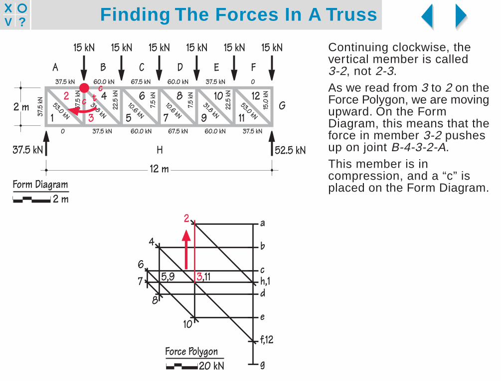
Continuing clockwise, thevertical member is called3-2, not 2-3.As we read from 3 to 2 on theForce Polygon, we are movingupward. On the FormDiagram, this means that theforce in member 3-2 pushesup on joint B-4-3-2-A.This member is incompression, and a “c” isplaced on the Form Diagram.
2 4 6 8 10 12
37.5
kN
22.5
kN
7.5 kN
7.5 kN
22.5
kN
15.0
kN
53.0 kN
31.8 kN10.6 kN
10.6 kN31.8 kN
53.0 kN
H
G
FEDCBA
15 kN15 kN15 kN15 kN15 kN15 kN
12 m
2 m1 3 5 7 9 11
37.5 kN
37.5
kN
37.5 kN 60.0 kN 67.5 kN 60.0 kN 37.5 kN 0
0 37.5 kN 60.0 kN 67.5 kN 60.0 kN 37.5 kN
52.5 kN
ctc
a
b
c
d
e
f,12
g
h,1
2
4
67
8
5,9
10
3,11
Force Polygon20 kN
Form Diagram2 m
Finding The Forces In A Truss?V
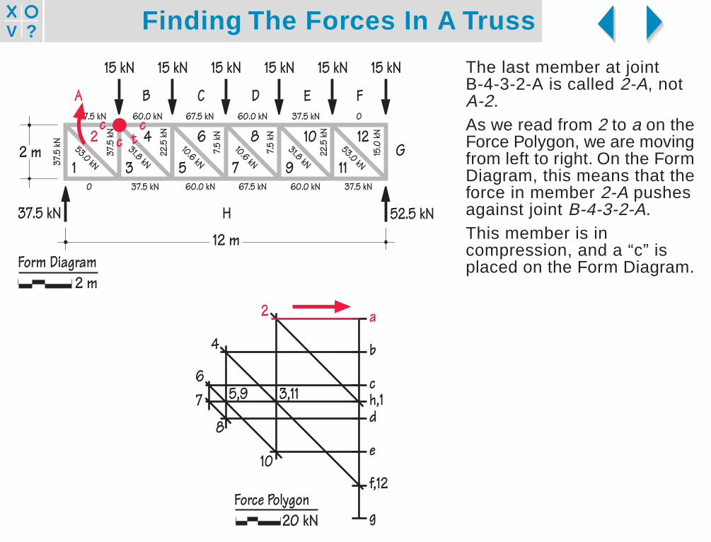
The last member at jointB-4-3-2-A is called 2-A, notA-2.As we read from 2 to a on theForce Polygon, we are movingfrom left to right. On the FormDiagram, this means that theforce in member 2-A pushesagainst joint B-4-3-2-A.This member is incompression, and a “c” isplaced on the Form Diagram.
2 4 6 8 10 12
37.5
kN
22.5
kN
7.5 kN
7.5 kN
22.5
kN
15.0
kN
53.0 kN
31.8 kN10.6 kN
10.6 kN31.8 kN
53.0 kN
H
G
FEDCBA
15 kN15 kN15 kN15 kN15 kN15 kN
12 m
2 m1 3 5 7 9 11
37.5 kN
37.5
kN
37.5 kN 60.0 kN 67.5 kN 60.0 kN 37.5 kN 0
0 37.5 kN 60.0 kN 67.5 kN 60.0 kN 37.5 kN
52.5 kN
ctc
c
a
b
c
d
e
f,12
g
h,1
2
4
67
8
5,9
10
3,11
Force Polygon20 kN
Form Diagram2 m
Finding The Forces In A Truss?V
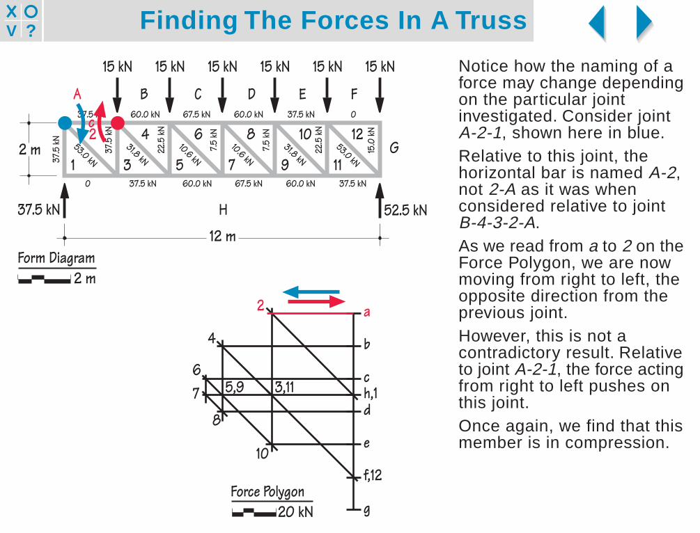
Notice how the naming of aforce may change dependingon the particular jointinvestigated. Consider jointA-2-1, shown here in blue.Relative to this joint, thehorizontal bar is named A-2,not 2-A as it was whenconsidered relative to jointB-4-3-2-A.As we read from a to 2 on theForce Polygon, we are nowmoving from right to left, theopposite direction from theprevious joint.However, this is not acontradictory result. Relativeto joint A-2-1, the force actingfrom right to left pushes onthis joint.Once again, we find that thismember is in compression.
2 4 6 8 10 12
37.5
kN
22.5
kN
7.5 kN
7.5 kN
22.5
kN
15.0
kN
53.0 kN
31.8 kN10.6 kN
10.6 kN31.8 kN
53.0 kN
H
G
FEDCBA
15 kN15 kN15 kN15 kN15 kN15 kN
12 m
2 m1 3 5 7 9 11
37.5 kN
37.5
kN
37.5 kN 60.0 kN 67.5 kN 60.0 kN 37.5 kN 0
0 37.5 kN 60.0 kN 67.5 kN 60.0 kN 37.5 kN
52.5 kN
c
a
b
c
d
e
f,12
g
h,1
2
4
67
8
5,9
10
3,11
Force Polygon20 kN
Form Diagram2 m
Finding The Forces In A Truss?V
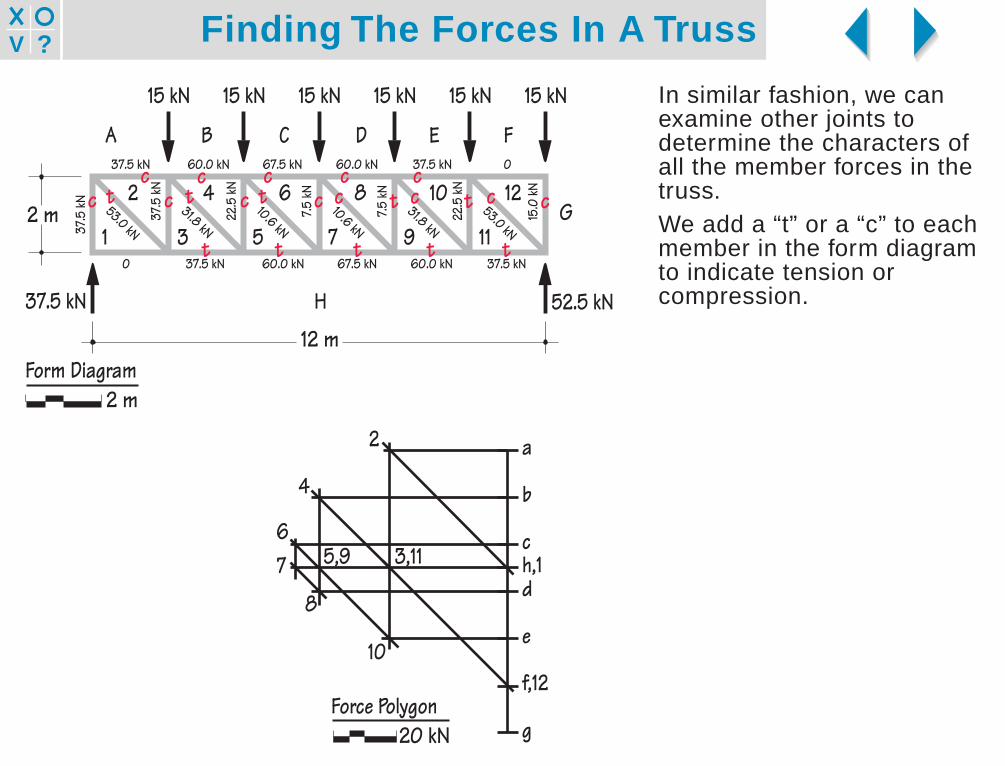
In similar fashion, we canexamine other joints todetermine the characters ofall the member forces in thetruss.We add a “t” or a “c” to eachmember in the form diagramto indicate tension orcompression.
2 4 6 8 10 12
37.5
kN
22.5
kN
7.5 kN
7.5 kN
22.5
kN
15.0
kN
53.0 kN
31.8 kN10.6 kN
10.6 kN31.8 kN
53.0 kN
H
G
FEDCBA
15 kN15 kN15 kN15 kN15 kN15 kN
12 m
2 m1 3 5 7 9 11
37.5 kN
37.5
kN
37.5 kN 60.0 kN 67.5 kN 60.0 kN 37.5 kN 0
0 37.5 kN 60.0 kN 67.5 kN 60.0 kN 37.5 kN
52.5 kN
ctc
cc t t c tc
c cc
t t
cc
t t t
t c c
a
b
c
d
e
f,12
g
h,1
2
4
67
8
5,9
10
3,11
Force Polygon20 kN
Form Diagram2 m
Finding The Forces In A Truss?V
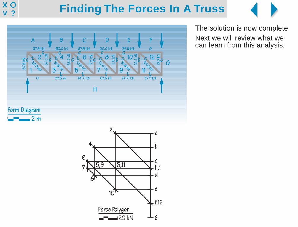
The solution is now complete.Next we will review what wecan learn from this analysis.
37.5
kN
37.5 kN 60.0 kN 67.5 kN 60.0 kN 37.5 kN 0
Form Diagram2 m
37.5
kN
22.5
kN
7.5 kN
7.5 kN
22.5
kN
15.0
kN
53.0 kN
31.8 kN10.6 kN
10.6 kN31.8 kN
53.0 kN
H
G
0 37.5 kN 60.0 kN 67.5 kN 60.0 kN 37.5 kN
ctc
cc t t c tc
c cc
t t
cc
t t t
t c c
FEDCBA
2 4 6 8 10 12
1 3 5 7 9 11
a
b
c
d
e
f,12
g
h,1
2
4
67
8
5,9
10
3,11
Force Polygon20 kN

Finding The Forces In A Truss?V
What can we learn from thecompleted analysis?The force polygon shows usthat forces in the top andbottom chords are highest atthe center and diminish tominimum values at the endsof the span.Forces in the interiormembers (the diagonals andverticals) follow the oppositepattern: They are highest atthe ends and minimal at thecenter of the span.
2 4 6 8 10 12
37.5
kN
22.5
kN
7.5 kN
7.5 kN
22.5
kN
15.0
kN
53.0 kN
31.8 kN10.6 kN
10.6 kN31.8 kN
53.0 kN
H
G
FEDCBA
15 kN15 kN15 kN15 kN15 kN15 kN
12 m
2 m1 3 5 7 9 11
37.5 kN
37.5
kN
37.5 kN 60.0 kN 67.5 kN 60.0 kN 37.5 kN 0
0 37.5 kN 60.0 kN 67.5 kN 60.0 kN 37.5 kN
52.5 kN
ctc
cc t t c tc
c cc
t t
cc
t t t
t c c
a
b
c
d
e
f,12
g
h,1
2
4
67
8
5,9
10
3,11
Force Polygon20 kN
Form Diagram2 m

Finding The Forces In A Truss?V
The characters of the forcesin the interior membersreverse at midspan. This isbecause the truss has thesame orientation of diagonalsthroughout its length, and isthus geometricallyunsymmetrical.If the diagonals in one half ofthe truss were mirror imagesof those in the other half,which is the more usualarrangement, the charactersof the forces in the interiormembers would follow thesame pattern throughout. Thatis, all diagonals would be ineither tension or compression,and all verticals would havethe opposite force character.
2 4 6 8 10 12
37.5
kN
22.5
kN
7.5 kN
7.5 kN
22.5
kN
15.0
kN
53.0 kN
31.8 kN10.6 kN
10.6 kN31.8 kN
53.0 kN
H
G
FEDCBA
15 kN15 kN15 kN15 kN15 kN15 kN
1 3 5 7 9 11
37.5 kN
37.5
kN
37.5 kN 60.0 kN 67.5 kN 60.0 kN 37.5 kN 0
0 37.5 kN 60.0 kN 67.5 kN 60.0 kN 37.5 kN
52.5 kN
ctc
cc t t c tc
c cc
t t
cc
t t t
t c c2 m
12 m
a
b
c
d
e
f,12
g
h,1
2
4
67
8
5,9
10
3,11
Force Polygon20 kN
Form Diagram2 m

Finding The Forces In A Truss?V
Changing the depth of thetruss.What happens if the depth ofthe truss is reduced by half,while the span and loads staythe same? The ForcePolygons tell the story:Member forces in the top andbottom chords of the trussexactly double.Forces in the diagonalsincrease, but by a lesseramount.Forces in the verticalmembers remain unchanged.In general, member forces inthe top and bottom chords areinversely proportional to thedepth of the truss.
h
Form Diagram
F
2F h/2
Form Diagram
Force Polygon
Force Polygon
Finding The Forces In A Truss?V
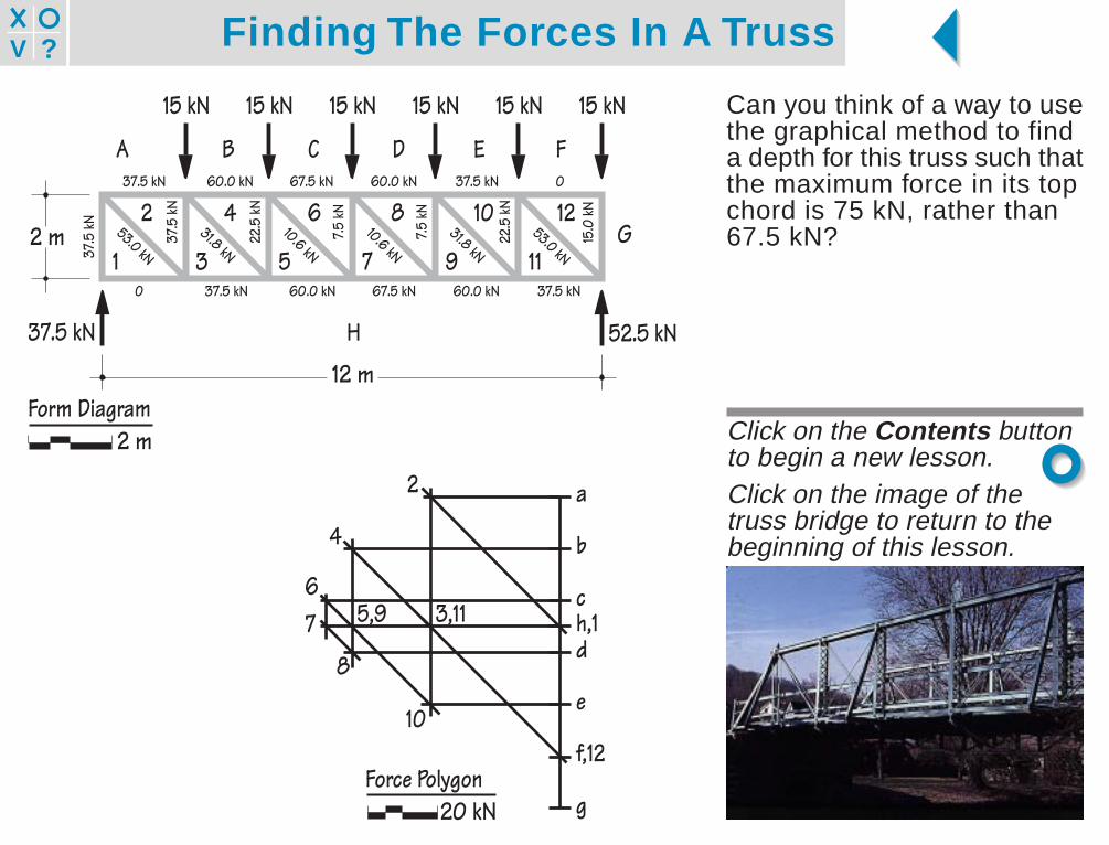
Can you think of a way to usethe graphical method to finda depth for this truss such thatthe maximum force in its topchord is 75 kN, rather than67.5 kN?
Click on the Contents buttonto begin a new lesson.Click on the image of thetruss bridge to return to thebeginning of this lesson.
2 4 6 8 10 12
37.5
kN
22.5
kN
7.5 kN
7.5 kN
22.5
kN
15.0
kN
53.0 kN
31.8 kN10.6 kN
10.6 kN31.8 kN
53.0 kN
H
G
FEDCBA
15 kN15 kN15 kN15 kN15 kN15 kN
12 m
2 m1 3 5 7 9 11
37.5 kN
37.5
kN
37.5 kN 60.0 kN 67.5 kN 60.0 kN 37.5 kN 0
0 37.5 kN 60.0 kN 67.5 kN 60.0 kN 37.5 kN
52.5 kN
a
b
c
d
e
f,12
g
h,1
2
4
67
8
5,9
10
3,11
Force Polygon20 kN
Form Diagram2 m