finalreport - team suture (1) (1)
TRANSCRIPT

DESIGN REPORT
ME 4054W: Automated Suturing Device
Team Members: Advisors: Sponsor:
Daniel Chryst Jeff Reineke UMN Medical Devices Center
Amanda Eidem Jenna Iaizzo
Michael Serra
Andrew Wilcox Date:
Bowen Yang May 8, 2014
1
Executive Summary In the case of a substantial wound or laceration, sutures are used to assist the body in closing and sealing the
wound. Significant time is spent in attempting to close these wounds even though it is ideal to close the
wounds as quickly as possible to negate infection and reduce blood loss. The objective of this project is to
create a device that allows medical professionals and military personnel to easily close a wound in an efficient
manner. A device that accomplishes a clean and efficient stitching is advantageous in delaying the onset of
tissue necrosis and keeping the wound uninfected. It is envisioned that this device will be mobile and robust
enough to be used in situations in which the time necessary to deliver the patient to more intensive medical
care is greater than three hours. This device will be developed for the main purpose of improved health care by
introducing an easier solution for suturing practices.
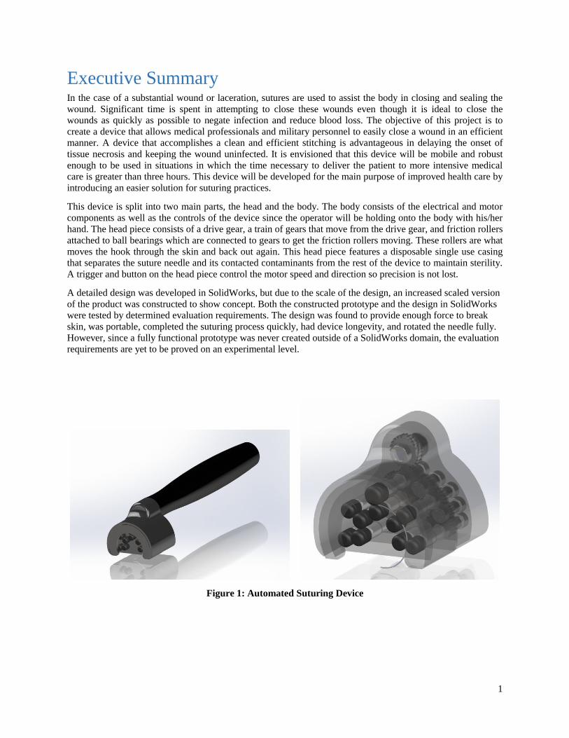
This device is split into two main parts, the head and the body. The body consists of the electrical and motor
components as well as the controls of the device since the operator will be holding onto the body with his/her
hand. The head piece consists of a drive gear, a train of gears that move from the drive gear, and friction rollers
attached to ball bearings which are connected to gears to get the friction rollers moving. These rollers are what
moves the hook through the skin and back out again. This head piece features a disposable single use casing
that separates the suture needle and its contacted contaminants from the rest of the device to maintain sterility.
A trigger and button on the head piece control the motor speed and direction so precision is not lost.
A detailed design was developed in SolidWorks, but due to the scale of the design, an increased scaled version
of the product was constructed to show concept. Both the constructed prototype and the design in SolidWorks
were tested by determined evaluation requirements. The design was found to provide enough force to break
skin, was portable, completed the suturing process quickly, had device longevity, and rotated the needle fully.
However, since a fully functional prototype was never created outside of a SolidWorks domain, the evaluation
requirements are yet to be proved on an experimental level.
Figure 1: Automated Suturing Device

2
TABLE OF CONTENTS
Executive Summary .............................................................................................................................................. 1
1. Problem Definition ........................................................................................................................................... 4
1.1 Problem Scope ............................................................................................................................................ 4
1.2 Technical Review ....................................................................................................................................... 4
1.3 Design Requirements .................................................................................................................................. 7
2. Design Description ........................................................................................................................................... 8
2.1 Overview .................................................................................................................................................... 8
2.2 Detailed Description ................................................................................................................................... 9
2.2.1 Design Block Diagram ........................................................................................................................ 9
2.2.2 Disposable Head .................................................................................................................................. 9
2.2.3 Connection ......................................................................................................................................... 11
2.2.4 Permanent Head ................................................................................................................................. 12
2.2.5 Handle ............................................................................................................................................... 12
2.3 Use ............................................................................................................................................................ 13
3. Evaluation ....................................................................................................................................................... 14
3.1 Overview .................................................................................................................................................. 14
3.2 Requirements Testing ............................................................................................................................... 14
3.2.1 Skin Breakage .................................................................................................................................... 14
3.2.2 Portability .......................................................................................................................................... 15
3.2.3 Quick Performance ............................................................................................................................ 15
3.2.4 Device Longevity .............................................................................................................................. 15
3.2.5 Needle Completes Full Rotation ........................................................................................................ 16
3.2.6 Cost .................................................................................................................................................... 16
3.3 Prototype ................................................................................................................................................... 17
4. Discussion ....................................................................................................................................................... 18
4.1 Assessment ............................................................................................................................................... 18
4.2 Next Steps ................................................................................................................................................. 18
5. References ...................................................................................................................................................... 19
6. Appendices ..................................................................................................................................................... 20
Appendix A: Technology Review Support ..................................................................................................... 20

3
Appendix B: Alternative Concepts and Concept Selection ............................................................................ 21
Appendix C: Design Supporting Documents .................................................................................................. 27
C.1 Bill of Materials/ Assembly Drawings................................................................................................. 27
C.2 Part Drawings ...................................................................................................................................... 31
C.3 Manufacturing Plan .............................................................................................................................. 37
Appendix D: Engineering Analysis ................................................................................................................ 38
D.1 Stress & Deformation Analysis ........................................................................................................... 38
Appendix E: Evaluation Reports .................................................................................................................... 41
Criterion 1: Skin Breakage ......................................................................................................................... 41
Criterion 2: Portability ................................................................................................................................ 44
Criterion 3: Time to perform suturing process ........................................................................................... 45
Criterion 4: Device Longevity .................................................................................................................... 46
Criterion 5: Needle Completes Full Rotation ............................................................................................. 47
Appendix F: Cost Analysis ............................................................................................................................. 49
Appendix G: Failure Modes and Effect Analysis ........................................................................................... 50
........................................................................................................................................................................ 50
Appendix H: Environmental Impact ............................................................................................................... 51
Appendix I: Codes, Standards and Safety ...................................................................................................... 52
Appendix J: Patent Search .............................................................................................................................. 53
4
1. Problem Definition
1.1 Problem Scope The objective of this project is to facilitate the design of an automated suturing device. This device will be
geared for use in a first response, “in the field”, situation where immediate attention is needed to close an open
wound or laceration. This device will provide an efficient way to close a laceration so that the wounded patient
can be transported more safely while reducing the risk of infection and delaying tissue necrosis before more
intensive medical attention can be applied. The cosmetics of the wound closure is not a main priority of this
project. Although it is important to limit scarring, our main focus is to address serious complications relating to
open wounds. This device will provide an efficient method of successfully closing a wound in an effort to
preserve the health of the patient. This project exists for the main purpose of saving lives by providing a
solution for medical professionals to suture patients more swiftly.
1.2 Technical Review Wound closure methods and suturing date back to having been used by the Egyptians in 2000 BC. Medical
wound closure needs to be implemented when a tissue has been disrupted to where it cannot heal naturally.
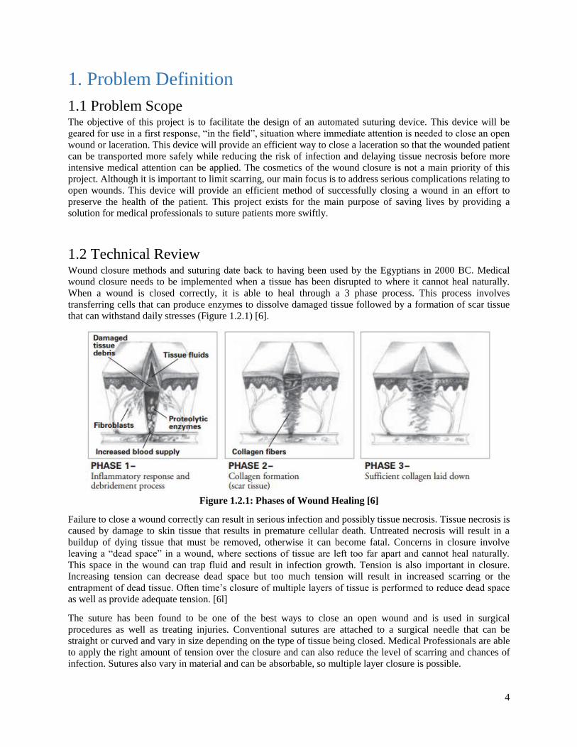
When a wound is closed correctly, it is able to heal through a 3 phase process. This process involves
transferring cells that can produce enzymes to dissolve damaged tissue followed by a formation of scar tissue
that can withstand daily stresses (Figure 1.2.1) [6].
Figure 1.2.1: Phases of Wound Healing [6]
Failure to close a wound correctly can result in serious infection and possibly tissue necrosis. Tissue necrosis is
caused by damage to skin tissue that results in premature cellular death. Untreated necrosis will result in a
buildup of dying tissue that must be removed, otherwise it can become fatal. Concerns in closure involve
leaving a “dead space” in a wound, where sections of tissue are left too far apart and cannot heal naturally.
This space in the wound can trap fluid and result in infection growth. Tension is also important in closure.
Increasing tension can decrease dead space but too much tension will result in increased scarring or the
entrapment of dead tissue. Often time’s closure of multiple layers of tissue is performed to reduce dead space
as well as provide adequate tension. [6l]
The suture has been found to be one of the best ways to close an open wound and is used in surgical
procedures as well as treating injuries. Conventional sutures are attached to a surgical needle that can be
straight or curved and vary in size depending on the type of tissue being closed. Medical Professionals are able
to apply the right amount of tension over the closure and can also reduce the level of scarring and chances of
infection. Sutures also vary in material and can be absorbable, so multiple layer closure is possible.

5
Suturing an open wound can be a time consuming and complicated process that requires intricate knot tying
and a high level of skill to successfully complete the process. There are continuous suturing methods that
involve less knot tying, but require more tension and skill and are not as secure [6]. There are also alternative
methods that involve individually tied stitches to make more secure closures. The time and intricacy that it
takes to close a wound properly would deter most first responders from using suturing methods in the field [1].
However, necrosis development is a factor of time and field closure of the wound becomes necessary if the
patient cannot receive hospital care within 3 hours of the injury [2].
Current field wound treatment and closure methods include hemostatic dressings, adhesive strips, and
hemorrhage control methods such as a tourniquet. These methods are used in both military and EMS
situations. Each method of closure is situational as some are preferable depending on the injury severity, shape
of wound, time to reach sterile medical treatment, medical supply, and other variables.
In many first response situations of treating an open wound due to injury, the main concern is creating an
effective clot before creating a closure. One of the more successful ways to create this clot is the use of a
hemostatic dressing. Hemostatic dressings can be in bandage, gauze, or powder form and allow for quick
attention and flexibility to difficult wounds. They use bio-friendly material that helps prevent infections.
Common hemostatic dressings in the market are QuikClot, HemCon, and Celox. These dressings have been
most commonly used in military settings and are now being implemented in EMS situations. Most hemostatic
agent treatments are followed with a bandage to close the wound [7].
Tourniquets are also common in the military setting for first response wound care. A tourniquet is usually a
bandage that is wrapped around a limb that has suffered a severe or life-threatening injury. By tightening the
tourniquet around the limb, an adequate pressure can be applied to create a clot and a temporary closure can be
attained. Tourniquets are ideal in emergency situations as they can be applied quickly and can be made from a
variety of materials such as cloth, though many problems can arise with incorrect application of a tourniquet. If
applied incorrectly, the tourniquet can stop blood flow to the arteries, raise blood pressure, or apply pressure to
a sensitive location. For this reason, tourniquets are only used in last resort situations where direct pressure
cannot be easily applied [9].
Figure 1.2.2 iTClamp
A recent development in wound closure is the IT clamp. Figure 1.2.2 shows the device. The clamp is able to
apply a temporary wound closure by using suture needles that pierce the skin and bring the open tissue
together. The device works similarly to a hair clip in that it uses a torsional spring to apply the closing forces.
This allows for a quick application that creates a clot as well as a temporary wound closure. The device
requires minimal training and provides an option that could be used in military and EMS applications. This
device is not without limitations as it is limited in closure size and is more ideal for straight line opening
closures that are not as common in traumatic injuries. [8]
6
One more common type of field closure method is the use of adhesive bandages, such as a butterfly bandage.
These bandages also allow for a quick closure method once a clot is made. They work as an external closure
that uses tension to pull the sides of a wound together. Although they are optimal in time sensitive situations,
adhesive bandages apply only a limited amount of tension and hold for a limited amount of time. They are not
always able to make an acceptable closure, especially with deep tissue damage.
As for suturing methods, there are several current suturing devices that improve the speed and ease of
operation, including barbed sutures. Barbed sutures are sutures that are one directional and are used in
continuous suturing methods. They contain frayed barbs that prevent the suture from going in a reverse
direction. These barbs latch into the tissue and eliminate a need for constant knot tying in an operation. The
sutures can also be absorbable in tissue and be used in multiple layered suturing applications. The barbed
suture is a relative new technology that have been developed by medical device companies such as Covidien or
Quill. The V-Loc wound closure device made by Covidien has been found to close incisions up to 50% faster
than traditional sutures [10].
There are also current patented automated devices that assist in simplifying the method of continuous suturing.
These designs focus on an automated movement of the suture needle such as passing through skin or creating a
suturing motion. US 8465504 B2 uses a helical needle and hooking mechanism to pass a suture through skin
and create knots to perform a linear closure. WO 2013167885 A1, a patent for Sutrue, forces a needle along a
circular path as a means of resetting a needle for each insertion. These designs are both advantageous in aiding
a more efficient suturing operation, but more design work could be implemented in them to create a more
autonomous suturing tool for a variety of situations. An automated suturing device of this kind would be
effective for obscure closures and require less training which could ultimately bridge suturing applications to
first response setting.
7
1.3 Design Requirements In order to effectively design the automated suturing device, it must meet a series of design requirements.
Firstly, the device must be clean, as suturing is a sterile operation and infection can happen easily if the wound
is not cleaned properly or if the suturing instruments are contaminated. The device must not endanger the
patient and be robust enough so as not the fail when in use. The quality of the wound closure must be of equal
or greater quality to traditional suturing. Stability, avoidance of skin tension, and skin alignment are also other
requirements that would like to be reached. Lastly, the device must be reasonably priced. If we are to be
successful in replacing traditional suturing methods, the product must not incur a great cost so as to remain a
desirable option over traditional suturing. Also, ass a device that is going to be used in first response situations,
it should be inexpensive and easily replaced. A summary of the design requirements can be seen in Table
1.3.1. Listed are the highest priority design requirements, and the complete table is shown in the appendix.
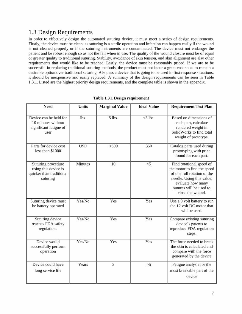
Table 1.3.1 Design requirement
Need Units Marginal Value Ideal Value Requirement Test Plan
Device can be held for
10 minutes without
significant fatigue of
user
lbs. 5 lbs. <3 lbs. Based on dimensions of
each part, calculate
rendered weight in
SolidWorks to find total
weight of prototype.
Parts for device cost
less than $1000
USD <500 350 Catalog parts used during
prototyping with price
found for each part.
Suturing procedure
using this device is
quicker than traditional
suturing
Minutes 10 <5 Find rotational speed of
the motor to find the speed
of one full rotation of the
needle. Using this value,
evaluate how many
sutures will be used to
close the wound.
Suturing device must
be battery operated
Yes/No Yes Yes Use a 9 volt battery to run
the 12 volt DC motor that
will be used.
Suturing device
reaches FDA safety
regulations
Yes/No Yes Yes Compare existing suturing
device’s patents to
reproduce FDA regulation
steps.
Device would
successfully perform
operation
Yes/No Yes Yes The force needed to break
the skin is calculated and
compare with the force
generated by the device
Device could have
long service life
Years 3 >5 Fatigue analysis for the
most breakable part of the
device
8
2. Design Description
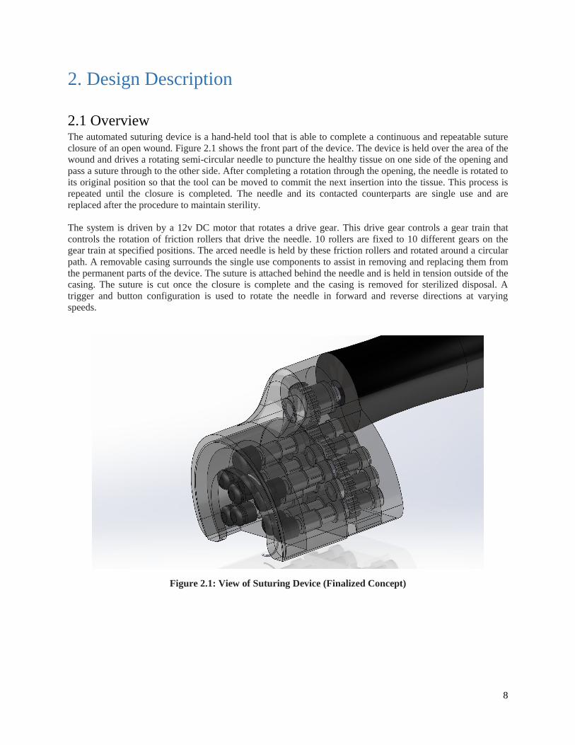
2.1 Overview The automated suturing device is a hand-held tool that is able to complete a continuous and repeatable suture
closure of an open wound. Figure 2.1 shows the front part of the device. The device is held over the area of the
wound and drives a rotating semi-circular needle to puncture the healthy tissue on one side of the opening and
pass a suture through to the other side. After completing a rotation through the opening, the needle is rotated to
its original position so that the tool can be moved to commit the next insertion into the tissue. This process is
repeated until the closure is completed. The needle and its contacted counterparts are single use and are
replaced after the procedure to maintain sterility.
The system is driven by a 12v DC motor that rotates a drive gear. This drive gear controls a gear train that
controls the rotation of friction rollers that drive the needle. 10 rollers are fixed to 10 different gears on the
gear train at specified positions. The arced needle is held by these friction rollers and rotated around a circular
path. A removable casing surrounds the single use components to assist in removing and replacing them from
the permanent parts of the device. The suture is attached behind the needle and is held in tension outside of the
casing. The suture is cut once the closure is complete and the casing is removed for sterilized disposal. A
trigger and button configuration is used to rotate the needle in forward and reverse directions at varying
speeds.
Figure 2.1: View of Suturing Device (Finalized Concept)

9
2.2 Detailed Description
2.2.1 Design Block Diagram
Figure 2.2.1: Block Diagram of Suturing Device
The device consists of three main assemblies: the disposable head, the permanent head, and the handle. The
single use removable casing facilitates the rotation of the needle by housing the components that drive the
needle directly. The permanent head houses the gear system that provides motion to the single use components
of the disposable head. The handle houses the motor and user interface system in an ergonomic design.
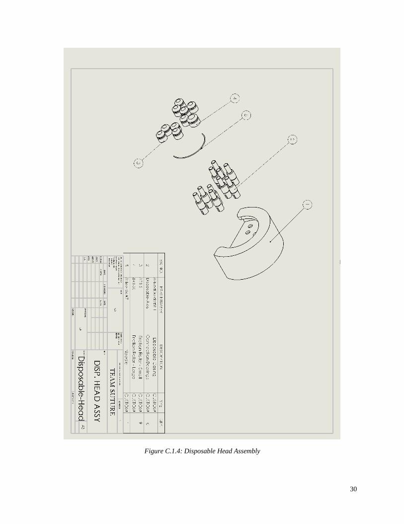
2.2.2 Disposable Head The disposable head contains the needle, suture, and friction rollers. It is designed to snap fit into the
permanent head to provide a seamless transition between uses. The assembly is designed for single use and
will be prepackaged and sterilized. The casing is left open to allow the suture to be held in front of the device
to avoid tangling. The friction rollers, needle, and suture are explained in more detail in the following
subsections.
Figure 2.2.3: Disposable Head Assembly

10
2.2.2.1 Friction Rollers
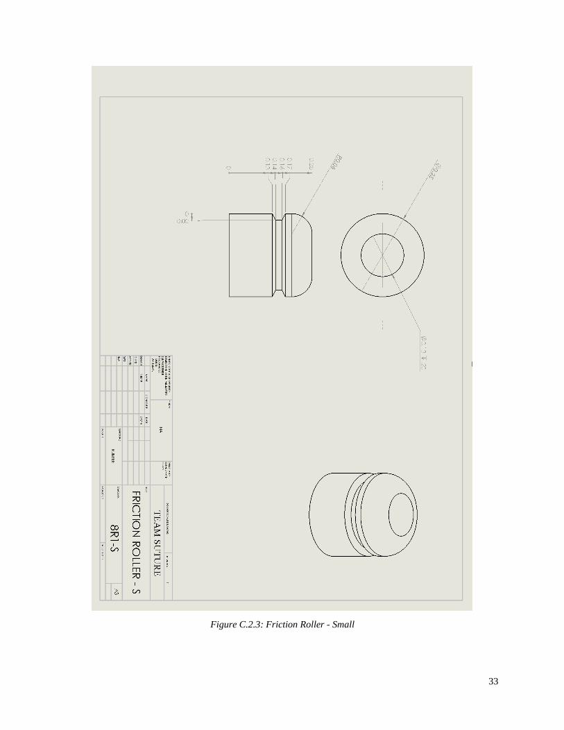
The friction rollers apply the driving force from the gear system to the needle and are grooved to hold the
position of the needle (Figure 2.2.4). The device implements ten friction rollers that constrain the needle to a
circular path and drive the rotation of the needle. The rollers are set up in pairs that contact the needle at five
separate points. The rollers are made of a chloroprene rubber material that provides a high friction coefficient.
The rollers are designed to be elastic and deform when the needle contacts the roller. This increases the contact
area and provide more frictional force. The rollers are press fit over a bearing that is coupled to the driving
gear system. This bearing snap fits onto the axle of the drive system and is easily removed for single use and is
shown in the appendix.
Figure 2.2.4: Grooved Rubber Friction Roller
2.2.2.2 Needle
A stainless steel surgical needle is used to pierce the skin and carry the suture through to close the wound. The
needle diameter will vary per disposable head package and will provide the consumer with an option as
different situations warrant different needle sizes. The needle will be of semi-circular curvature that ensures
our device will always be in contact to drive the needle. This needle diameter is greater than the opening
between the two friction rollers. When the needle is forced between the rollers, the resultant stress deforms the
rollers and cause an increase in contact area to increase the frictional force. The suture is attached to the end so
that it follows the needle through the skin.
Figure 2.2.5: 5/8 Circle Needle Fit Into Friction Rollers

11
2.2.2.3 Suture
The suture in closing methods is the material that holds the wound together once the procedure is complete and
can be absorbed in the skin. The adhered suture will be a barbed quill-type suture that will allow for
continuous motion. No knots will have to be tied as the barbs in the suture will grasp penetrated skin and
prevent reverse motion. This suture will be held in tension in front of the casing by the operator. Once each
pass of the needle is made, the operator will have to lift the device to pull the rest of the suture through before
making the next puncture. There will be enough suture material with the packaged needle casing to last the
duration of the suture operation.
Figure 2.2.6: Barbed Suture Material
2.2.3 Connection The disposable head casing contains sealed bearings that serve as the connection between the permanent and
disposable heads. These bearings harness the rotation of the gear train as they snap fit into the driving axles of
the gear system and translate the rotation to the friction rollers. The bearings contain pins that are press fit into
the rubber friction rollers in the working area of the casing and are designed to release the axles without
damaging the permanent parts after use. The casing itself will have a snap fit design to create a stronger
connection to the permanent head. These fits are on the sides of the casing and snap into openings on the
permanent handle. When the two buttons on the sides of the permanent handle are pressed, the casing is forced
out of the openings and released for disposal.
Figure 2.2.7: Connection of Disposable Head and Permanent Handle

12
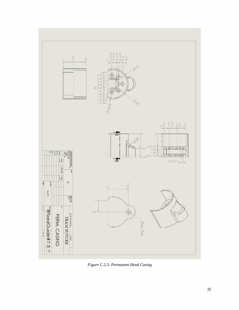
2.2.4 Permanent Head The permanent head contains the inter-workings that control the rotation of the needle. Inside the permanent
head is the gear train that controls the rotation of the friction rollers. This gear system is driven by a drive gear
that is operated by a 12v DC gear motor. The gear system rotates on frictionless ball bearings that are
extremely small in shape, and unfortunately, therefore very costly. The permanent head is therefore designed
to be reusable due to the expensive costs of the components that consist of the assembly.
2.2.4.1 Gear Train
The gear train is composed of 15 total spur gears where 1 is the drive gear that is coupled to the DC gear
motor, 10 are the functional gears that control the friction rollers, and 4 are translational gears that create the
spacing and control correct rotation directions (Figure 2.2.8). The drive gear (red) is largest gear at 14mm in
diameter and 24 teeth. The functional gears (black) and translational gears (gray) are 8mm in diameter and
have 14 teeth. These 14 gears are fixed above and below steel ball bearings.
Figure 2.2.8 Gear Train
2.2.5 Handle The handle itself serves as a comfortable hold to ease the operation of execution. There is an on/off switch, a
button, and a trigger that allow for forward and reverse rotation. Inside the handle resides all of the electrical
components that power the device. The device will be powered by a lithium-ion rechargeable battery. The
different parts of the handle will be described in more detail in the following subsections.
2.2.5.1 Motor and Electrical Components
Enclosed in the handle is all of the electrical components that will supply power to the motor. The device is
powered by a 9V lithium-ion rechargeable battery. There will be an input at the end that can be plugged into by
a wall adapter for easy charging. This is configured in a relay circuit so that the direction of current can be
changed to direct the rotation of the motor. The rotation of the device is controlled by a 12V DC gear motor
that is coupled to the drive gear. The motor has an output torque of 90N-cm.
2.2.5.2 Controls
The motor is controlled by two switches: one in the form of a button and the other is a trigger. The trigger is on
the bottom of the handle and is operated by the index finger. When pressed, the trigger sends voltage to the
motor and rotates the needle in the forward direction. When released, voltage will be cut from the motor and
the needle will stop its rotation. The button is on top of the handle and is easily accessible by the thumb. When

13
pressed and held, it will flip the relay to change the direction of the motor. When released, the relay will flip
back and rotate the needle in the forward direction.
2.3 Use A surgeon will begin by preparing the mechanism by inserting a needle to the specified region in the open head
of the suturing device. The hook will have a barbed suture of a specified length connected to it already, since
the tool uses one continuous stitch to close a wound. The device will use barbed sutures to take away the
necessity of tying a knot after every stitch. After the needle and suture are placed correctly, the path casing on
the head of the device can be closed. The surgeon then can begin to close the wound with the tool.
To begin, the surgeon would start at one of the edges of the wound*, and place both sides of the head on either
side of the wound opening. After, a trigger would be pressed and held to initiate the motion. The trigger is held
until the needle is pushed all the way into the skin. The needle is pressed through the rollers inside the head
and through the skin on one side of the wound. As the needle passes and breaks through the skin on the other
side, the rollers will catch the needle. The trigger is held until the needle fully comes loose from the wound.
The device can then be moved down the wound to start another cycle. The suture will follow out front of the
device, being held by the surgeon in the other hand. This cycle is repeated until the entire wound is closed.
If for any reason, the needle cannot move forward anymore, the surgeon can press and hold the button on the
top of the device and reverse the direction of the needle back into the tool with the trigger. Then, the needle
can be pushed forward again by releasing the button once again and using the trigger to initiate the motion.
Once the wound is closed and the last stitch has been made, the surgeon can cut the barbed suture, remove the
hook from the path casing by opening a release latch; this is a secure way to open and take out the hook safely
from the path casing. After the hook and leftover thread is taken out, the path casing is closed again, and the
tool is placed on a charging station for the tool to charge when not in use.
*The example wound is one described above, 3 cm in length, and 1 cm in depth. This is the original case,
however the tool will have removable heads for various types of wounds.
14
3. Evaluation
3.1 Overview In order to determine the quality of the product, it must be evaluated against the design requirements that were
determined earlier. The evaluation section discusses the steps taken to evaluate the quality and reliability of the
product. The device was found to have enough force to break skin and complete a suturing procedure. The
device was found to be lightweight and portable. The design allows the user to complete a suturing procedure
in a timely manner. The design incorporates a low cost, disposable head that will reduce the operating cost of
the product and make the device very marketable.
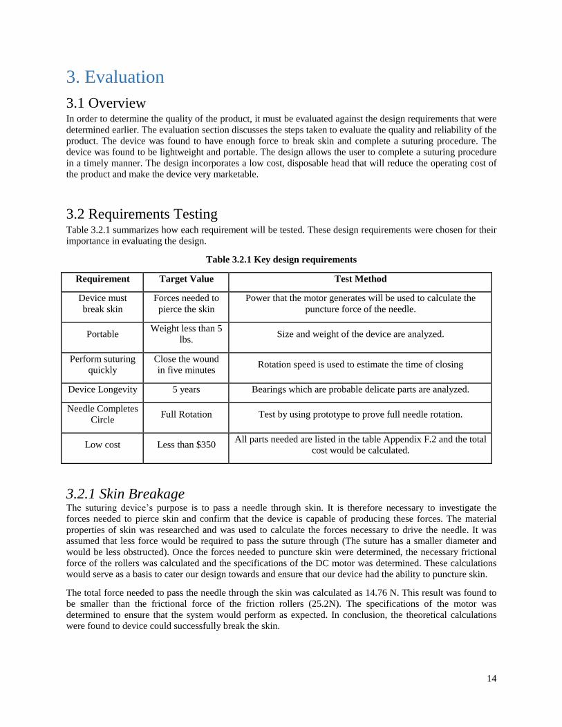
3.2 Requirements Testing Table 3.2.1 summarizes how each requirement will be tested. These design requirements were chosen for their
importance in evaluating the design.
Table 3.2.1 Key design requirements
Requirement Target Value Test Method
Device must
break skin
Forces needed to
pierce the skin
Power that the motor generates will be used to calculate the
puncture force of the needle.
Portable Weight less than 5
lbs. Size and weight of the device are analyzed.
Perform suturing
quickly
Close the wound
in five minutes Rotation speed is used to estimate the time of closing
Device Longevity 5 years Bearings which are probable delicate parts are analyzed.
Needle Completes
Circle Full Rotation Test by using prototype to prove full needle rotation.
Low cost Less than $350 All parts needed are listed in the table Appendix F.2 and the total
cost would be calculated.
3.2.1 Skin Breakage The suturing device’s purpose is to pass a needle through skin. It is therefore necessary to investigate the
forces needed to pierce skin and confirm that the device is capable of producing these forces. The material
properties of skin was researched and was used to calculate the forces necessary to drive the needle. It was
assumed that less force would be required to pass the suture through (The suture has a smaller diameter and
would be less obstructed). Once the forces needed to puncture skin were determined, the necessary frictional
force of the rollers was calculated and the specifications of the DC motor was determined. These calculations
would serve as a basis to cater our design towards and ensure that our device had the ability to puncture skin.
The total force needed to pass the needle through the skin was calculated as 14.76 N. This result was found to
be smaller than the frictional force of the friction rollers (25.2N). The specifications of the motor was
determined to ensure that the system would perform as expected. In conclusion, the theoretical calculations
were found to device could successfully break the skin.

15
3.2.2 Portability Portability is one design requirement that is fulfilled by having the dimensions of the main body smaller than
that of a single hand. This requirement is important so that the operator can maintain control throughout the
entire procedure. If the device was equal to or of greater size than a human hand, the operator would not have a
good grip on the device and therefore, would not make a quality suture. The area cannot be too small either,
otherwise, the same issues would occur; quality would also be at risk just as if it was too large for a hand.
These requirements were tested within the program, SolidWorks, by ensuring the dimensions were smaller
than the average human hand across genders. The average male hand is 189 mm tall, from the wrist to the
middle fingertip, as the female hand is a height of 172 mm. Therefore, the average is 180.5 mm tall. In order to
test this requirement, the surface area where the hand would hold the device has to be smaller, although not
drastically smaller, than the average human hand length.
From the device, the measurements are 160 mm around which is less than even an average female hand. This
allows diversity for the type of operator and ensures optimal stability from the hand, since the hand can wrap
around it quite easily. The device should be able to fit in normal drawers, whose dimensions are normally
20x17x6 inches. The length of the total device is about 7 inches and the height is 3 inches at the highest point
on the device. The automated suturing device is portable because it can fit in a normal size drawer as well as a
human hand easily. Hence, this requirement is fulfilled.
3.2.3 Quick Performance Performing a quick suturing operation is a key requirement for this device. Closing a wound in under 10
minutes, or ideally 5 minutes, is something that this device should strive for. If this device doesn’t suture a
wound in a quicker time than traditional hand suturing would take, the device would not be marketable.
When finding how long it would ideally take to close a wound using this device the RPM of the motor was
used to calculate how quickly it could drive a gear track that drove the needle. Once the speed of the needle
was found, the time it took for a complete rotation of the needle could also be found. The time it took for one
rotation of the needle was found to be 5.4 seconds. This result is comparable to an experimental suturing
procedure, and therefore this is a desirable result. If a 4 inch wound was taken and assuming a suture was
needed every ¼ of an inch, 16 sutures would have to be placed to close the wound. Each rotation would take
5.4 seconds, the total procedure time would take roughly 86 seconds, or just under 3 minutes to close a 4 inch
wound. This result is a great improvement over traditional suturing procedure duration.
3.2.4 Device Longevity Finding the life of the device is an important consideration. The device shouldn’t fail when it is needed most,
either from electric or stress fault. Therefore, the focus of this section will be on the most breakable part of the
device, the bearings. The friction rollers, which connect to the inside bearings, cause a radial load from the
needle moving through the skin onto the bearings. With the size of only less than ¼ in, the bearings are one of
the most delicate but also breakable part, which determines the longevity of this device.
From the result, the life of bearings could be expected as 40 years. The environment factors had not been taken
into account during the calculation, and for the small bearings like this, it could have huge impacts on the life
of the tool. However, given the fact that the design requirement for the device was only set to 5 years, the
conclusion could be drawn confidently that the device would meet its requirement.
16
3.2.5 Needle Completes Full Rotation A technical requirement of our device is to make sure that the needle rotates a full rotation during the
procedure by the friction rollers alone. The needle, since it is not a full circle, Figure E.4.1, will have gaps in
the rotation process where the needle is not being contacted fully by all the friction rollers. Thus, it is important
to dimension the distances between rollers to be smaller than the gap in the needle, otherwise stability of the
needle during rotation could be lost.
In the design of the prototype it was decided that the prototype would be used more as a demonstration of the
concept of the needle rotation, rather than a fully functional, scaled version. The prototype utilizes the friction
rollers to hold the needle during rotation using a friction groove. The prototype produced 10 full rotations of
the needle before it was deemed functional for full rotation. Having the needle rotate fully is a key requirement
for the device to work properly and for the suturing procedure to be done and finished correctly.
3.2.6 Cost Cost is always prominent in any kind of design project. The target customers were set to be first medical
responders, military personnel and people who live in an undeveloped areas. For them, expensive medical
procedures may be required to close a wound, or transportation via ambulance is needed, which can take time
and can have higher cost. So we need to provide them a device with a reasonable price.
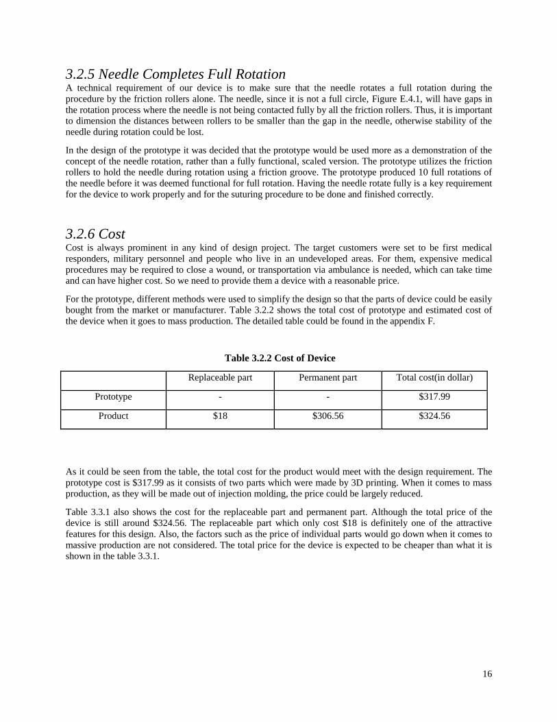
For the prototype, different methods were used to simplify the design so that the parts of device could be easily
bought from the market or manufacturer. Table 3.2.2 shows the total cost of prototype and estimated cost of
the device when it goes to mass production. The detailed table could be found in the appendix F.
Table 3.2.2 Cost of Device
Replaceable part Permanent part Total cost(in dollar)
Prototype - - $317.99
Product $18 $306.56 $324.56
As it could be seen from the table, the total cost for the product would meet with the design requirement. The
prototype cost is $317.99 as it consists of two parts which were made by 3D printing. When it comes to mass
production, as they will be made out of injection molding, the price could be largely reduced.
Table 3.3.1 also shows the cost for the replaceable part and permanent part. Although the total price of the
device is still around $324.56. The replaceable part which only cost $18 is definitely one of the attractive
features for this design. Also, the factors such as the price of individual parts would go down when it comes to
massive production are not considered. The total price for the device is expected to be cheaper than what it is
shown in the table 3.3.1.

17
3.3 Prototype Due to the physical constraints imposed by medical stitching practices, the product is forced to be very small.
For perspective, the device is required to provide motion to a half-circular needle that is only 1” in diameter.
To add further complexity to the product, the needle and resultant drive system has to be disposable after each
use. Therefore, the product has to provide complex motion in a very small package, whilst still being made
simply and cheaply enough to be disposable. These extreme design requirements have made necessary a
variety of innovative designs to complete the process and rapid prototyping difficult.
The design used “off the shelf” components whenever possible to save time and money in developing a
physical prototype. Since the product is on such a small scale, however, finding components small enough to
work for the prototype was difficult and costly. The precision necessary to fabricate the custom parts at such a
small scale was also costly and drawn out. These factors, when combined with our limited budget, drove the
decision to make a simplified prototype that demonstrates the major concepts of our design, whilst still being
inexpensive to produce. The prototype is to a larger scale than what is intended for the product, as it is more
important to show feasibility and functionality than struggle with dimension restriction on a smaller scale that
would require sacrifices to functionality and cost. The prototype can be seen below in Figure 3.3.1.
Figure 3.3.1: Prototype
The prototype provides a platform in which we can test the functionality of our concept as well as showcase
the basic concepts behind our design. It allows us to intuitively investigate the feasibility of our design and
generate ideas for improvements to future iterations of our product. An example of this can be seen in the
design of our friction roller system. One of the biggest sources of uncertainty originates from this system and a
significant amount of time will be needed to test and develop the rollers for future iterations. The prototype
provides insight to the functionality of the current design of the rollers, and allows us to improve upon them.
Different rollers can be installed by simply removing the existing heads and installing new ones. This
facilitates the testing of different materials in order to determine the best possible material suited for the final
product. The demonstration of how our product works through use of this prototype will also be hugely
beneficial when explaining our product to investors, peers, and faculty of the university.

18
4. Discussion
4.1 Assessment One strength of our tool is its speed. This device has the potential to suture a wound as well as a surgeon with
traditional tools. This tool will speed up a process that is both lengthy and repetitive. Otherwise lost limbs can
now be saved as well as lives, which is a priceless strength of this invention.
Another strength is the potential this device has. It can become the standard of what is used in modern
medicine for the foreseeable future as it not only standardizes suturing techniques by ensuring consistent,
reliable stitching, but it also has added safety benefits in reducing incidental needle stick that is common with
traditional stitching techniques.
As beneficial as this product can be, the design requirements are daunting. Due to the physical requirements set
by medical stitching, the components have to be produced on an extremely small scale whilst remaining cheap
enough to be disposable. The requirements leave few options to drive the needle in a reliable and cheap
manner. This makes innovative solutions a necessity in designing our product. With innovation comes
uncertainty and a significant amount of testing and analysis is expected to produce a functional model.
One negative about this design is that the head may be too complicated to create a low-cost replaceable piece.
The needle needs to be pushed through intricately, with rubber pieces pulling it through the track. The rubber
pieces, track, and anything else that touches the needle should be replaced to keep the device clean. This is one
of the major obstacles of this invention, and the device overcomes it well, at a cost higher than ideal.
4.2 Next Steps The goal of this project was to design an automated suturing device that could be used in first responder
situations. The deliverable of this project is a tool that can stitch up a wound physically and can be sold in the
marketplace. Our final design is only a beginning to what is a very complex solution. Therefore, to make the
invention succeed the next steps are crucial to accomplish.
For the future, the replaceable head piece should be the key parameter of focus. In its complexity arises cost
which needs to be reduced to make this product marketable, so honing in on the type of materials that would be
able to withstand the required motions of the head is necessary. The cost and complexity should be looked at to
see if something simpler or less expensive could work.
The electrical wiring of the tool is another part to analyze: a button, to make a bidirectional motor run back and
forth, and a latch, to detach the replaceable head, should also become realistic. The wiring and motor should fit
into the design body without any modification, though the wiring itself has not been finalized, and that would
be another component to ensure is optimal.
Along with all the technical aspects of the tool, putting a prototype in the hands of a surgeon or an experienced
nurse who has done wound closures before and taking down their impression and any faults they see in the
design would be necessary as well. It would make the tool more appealing and easier for the customer. When
testing and recording the impression of the voice of the customer from a surgeon, the final design requirements
should be observed as well. From a surgeon, the suture quality can be assessed as well as the ease of operation.

19
5. References
[1] Boudreaux, Josh: Emergency Medical Technician. Personal Interview. January 31, 2014.
[2] Mr. Stohl: Paramedic. Personal Interview. February 1st, 2014.
[3] Sauaia A, Moore FA, Moore EE, et al: Epidemiology of trauma deaths: A reassessment. Journal of Trauma.
1995.
[4] Eickmann, T., and E. Quane. "Total Knee Arthroplasty Closure with Barbed Sutures. National Center for Biotechnology Information. U.S. National Library of Medicine, Sept. 2010. Web. 06 Mar. 2014.
[5] "Medical Devices." Classify Your Medical Device. N.p., 3 Dec. 2013. Web. 29 Apr. 2014.
<http://www.fda.gov/MedicalDevices/DeviceRegulationandGuidance/Overview/ClassifyYourDevice
[6] “Wound Closure Manual” Ethicon, INC. Somerville, NJ 2005
<http://surgery.uthscsa.edu/pediatric/training/woundclosuremanual.pdf>
[7] Zeller, Jason. “Use of Hemostatic Dressings in Civilian EMS.” JEMS. July 26, 2008
<http://m.jems.com/article/training/use-hemostatic-dressings-civil>
[8] Clark, Jason. “Treating Hypoxia from a Hemorrhagic Standpoint.” JEMS. December, 2013
<http://www.jems.com/article/patient-care/new-tool-box>
[9] Lee, C. and K M Porter. “Tourniquet use in the civilian prehospital setting.” Emerg Med J. August 2007.
<http://www.ncbi.nlm.nih.gov/pmc/articles/PMC2660095/#__ffn_sectitle>
[10] “Secure. Fast. Effective.” V-Loc Barbed Sutures. Covidien. 2014
<surgical.covidien.com/products/wound-closure/barbed-sutures>
20
6. Appendices
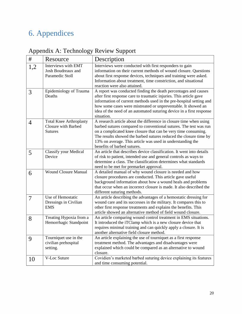
Appendix A: Technology Review Support
# Resource Description
1,2 Interviews with EMT
Josh Boudreaux and
Paramedic Stoll
Interviews were conducted with first responders to gain
information on their current methods of wound closure. Questions
about first response devices, techniques and training were asked.
Information about treatment, time constriction, and situational
reaction were also attained.
3 Epidemiology of Trauma
Deaths
A report was conducted finding the death percentages and causes
after first response care to traumatic injuries. This article gave
information of current methods used in the pre-hospital setting and
how some cases were mistreated or unpreventable. It showed an
idea of the need of an automated suturing device in a first response
situation.
4 Total Knee Arthroplasty
Closure with Barbed
Sutures
A research article about the difference in closure time when using
barbed sutures compared to conventional sutures. The test was run
on a complicated knee closure that can be very time consuming.
The results showed the barbed sutures reduced the closure time by
13% on average. This article was used in understanding the
benefits of barbed sutures.
5 Classify your Medical
Device
An article that describes device classification. It went into details
of risk to patient, intended use and general controls as ways to
determine a class. The classification determines what standards
need to be met for premarket approval.
6 Wound Closure Manual A detailed manual of why wound closure is needed and how
closure procedures are conducted. This article gave useful
background information about how a wound heals and problems
that occur when an incorrect closure is made. It also described the
different suturing methods.
7 Use of Hemostatic
Dressings in Civilian
EMS
An article describing the advantages of a hemostatic dressing for
wound care and its successes in the military. It compares this to
other first response treatments and explains the benefits. This
article showed an alternative method of field wound closure.
8 Treating Hypoxia from a
Hemorrhagic Standpoint
An article comparing wound control treatment in EMS situations.
It introduced the iTClamp which is a new closure device that
requires minimal training and can quickly apply a closure. It is
another alternative field closure method.
9 Tourniquet use in the
civilian prehospital
setting.
An article explaining the use of tourniquet as a first response
treatment method. The advantages and disadvantages were
explained which could be compared as an alternative to wound
closure.
10 V-Loc Suture Covidien’s marketed barbed suturing device explaining its features
and time consuming potential.

21
Appendix B: Alternative Concepts and Concept Selection Overview In the deciding process of the suturing device concept, many ideas were formed that ranged from infeasible, to
concept ideas that were similar to the actual created prototype. Each concept has been carefully reviewed and
the best one was chosen.
Concept Selection Ideas were ranked by design needs that were determined based off of customer needs. Each concept was
assigned a total number based on need being fulfilled or not. If a need was fulfilled by the concept then a “1”
was given. If the concept didn’t fulfill a need it was given a “-1” and if a need was unknown to be fulfilled or
not, then a “0” would be given. When all the needs were determined, a total number was found for each
concept. The concept with the highest number was the concept that was most seriously considered. The
“Pusher” concept received the highest number, according to fulfilling needs, and this concept was an influence
for the final prototype. Understanding that a needle needed was to be moved via a motor, or some other force
other than human effort, was a large consideration that was taken from this concept.
Table B.1 (Concept Selection Table)
22
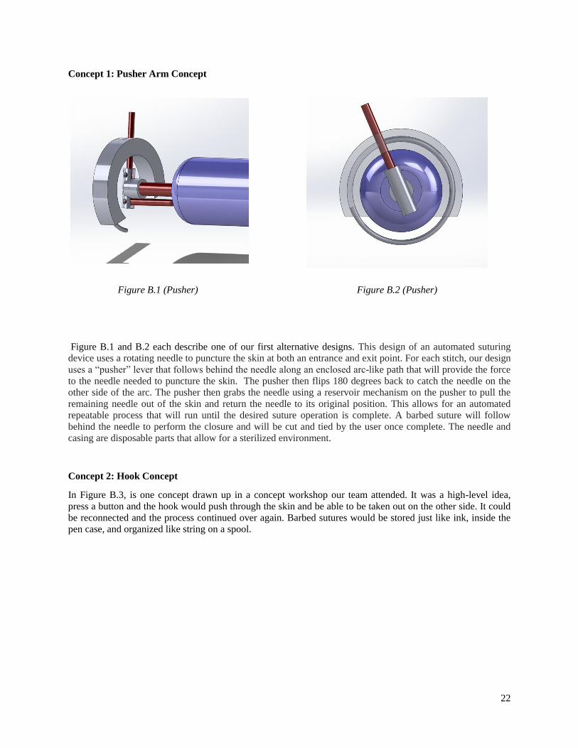
Concept 1: Pusher Arm Concept
Figure B.1 (Pusher) Figure B.2 (Pusher)
Figure B.1 and B.2 each describe one of our first alternative designs. This design of an automated suturing
device uses a rotating needle to puncture the skin at both an entrance and exit point. For each stitch, our design
uses a “pusher” lever that follows behind the needle along an enclosed arc-like path that will provide the force
to the needle needed to puncture the skin. The pusher then flips 180 degrees back to catch the needle on the
other side of the arc. The pusher then grabs the needle using a reservoir mechanism on the pusher to pull the
remaining needle out of the skin and return the needle to its original position. This allows for an automated
repeatable process that will run until the desired suture operation is complete. A barbed suture will follow
behind the needle to perform the closure and will be cut and tied by the user once complete. The needle and
casing are disposable parts that allow for a sterilized environment.
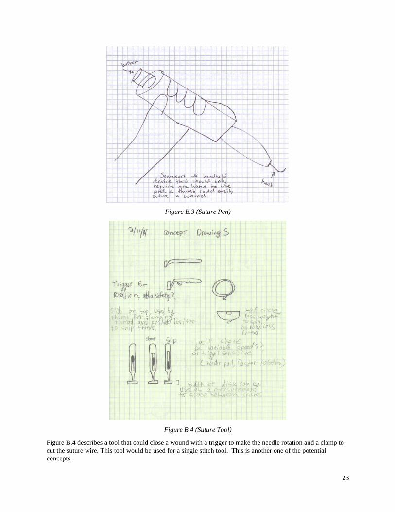
Concept 2: Hook Concept
In Figure B.3, is one concept drawn up in a concept workshop our team attended. It was a high-level idea,
press a button and the hook would push through the skin and be able to be taken out on the other side. It could
be reconnected and the process continued over again. Barbed sutures would be stored just like ink, inside the
pen case, and organized like string on a spool.
23
Figure B.3 (Suture Pen)
Figure B.4 (Suture Tool)
Figure B.4 describes a tool that could close a wound with a trigger to make the needle rotation and a clamp to
cut the suture wire. This tool would be used for a single stitch tool. This is another one of the potential
concepts.
24
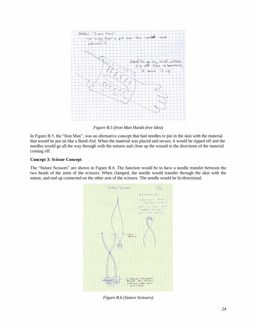
Figure B.5 (Iron Man Hands-free Idea)
In Figure B.5, the “Iron Man”, was an alternative concept that had needles to pin in the skin with the material
that would be put on like a Band-Aid. When the material was placed and secure, it would be ripped off and the
needles would go all the way through with the sutures and close up the wound in the directions of the material
coming off.
Concept 3: Scissor Concept
The “Suture Scissors” are shown in Figure B.6. The function would be to have a needle transfer between the
two heads of the arms of the scissors. When clamped, the needle would transfer through the skin with the
suture, and end up connected on the other arm of the scissors. The needle would be bi-directional.
Figure B.6 (Suture Scissors)

25
Figure B.7 (Bowed Needle)
Figure B.7 is a concept with a bowed needle transferring back and forth between the skin by means of rollers.
The skin would be raised by a clamp, and the bowed needle would pass through the skin with the suture wire
and be carried through by the rollers on both sides.
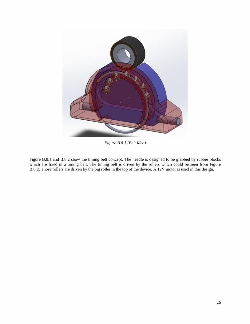
Concept 4: Track Concept
Figure B.8.2 (Belt Idea)
26
Figure B.8.1 (Belt Idea)
Figure B.8.1 and B.8.2 show the timing belt concept. The needle is designed to be grabbed by rubber blocks
which are fixed in a timing belt. The timing belt is driven by the rollers which could be seen from Figure
B.8.2. Those rollers are driven by the big roller in the top of the device. A 12V motor is used in this design.

27
Appendix C: Design Supporting Documents
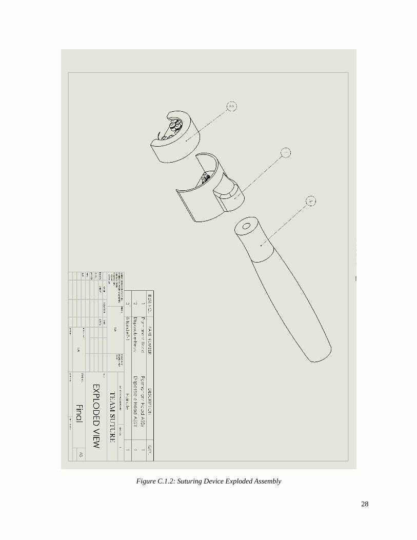
C.1 Bill of Materials/ Assembly Drawings The following drawings include a bill of materials that describe the components used in the assembly, lists the
components used as either custom or purchases components, and locates the components on the drawing.
Figure C.1.1: Suturing Device Assembly
28
Figure C.1.2: Suturing Device Exploded Assembly

29
Figure C.1.3: Permanent Head Assembly
30
Figure C.1.4: Disposable Head Assembly

31
C.2 Part Drawings
The following drawings show the details behind the custom components of the product.
Figure C.2.1: Disposable Head Casing

32
Figure C.2.2: Disposable Connection Bearing
33
Figure C.2.3: Friction Roller - Small

34
Figure C.2.4: Friction Roller - Medium
35
Figure C.2.5: Permanent Head Casing
36
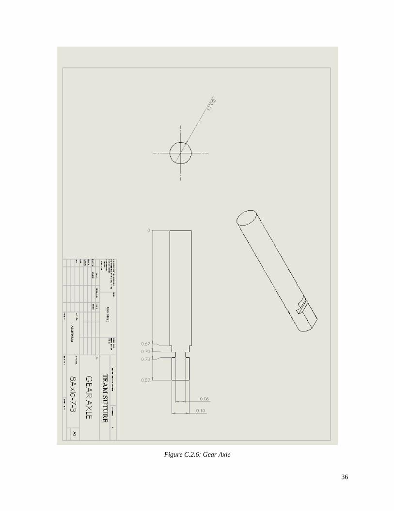
Figure C.2.6: Gear Axle
37
C.3 Manufacturing Plan Due to the complexity in many pieces of the design, it is important to reduce the manufacturing costs by
material and method. Most importantly, the disposable head is a piece that will need to be discarded after
single use. This means that all of these pieces should be lower in cost compared to the permanent parts of the
device. In order to do so the casing, roller, and pin will be injected molded plastic and rubber parts. This will
lower costs as these pieces can be ordered in bulk due to the need of multiple disposable heads after single use.
The needle and suture will be manufactured in cooperation of the company that sells the barbed sutures. No
modifications are made to the needle as the casing is designed to fit the stock half circle needles.
As for the permanent components of the device, they have to be more durable rigid parts that can endure many
cycles. Costs for manufacturing pieces like the gear axle will increase as they will be custom manufactured.
Electrical components, switches, motors, and bearings are all stock parts that the device was designed around.
The handle and permanent head will be rigid injected molded parts. The tolerances in the device are small due
to the scale of the device. This was the biggest concern of manufacturing in making the design. The designed
has been simplified to reduce problems with tolerances but they still remain an issue and could increase cost of
manufacturing.

38
Appendix D: Engineering Analysis This section includes stress & deformation analysis and operation time analysis. These analysis are essential to
understanding the device and make sure the device could work as expected.
D.1 Stress & Deformation Analysis Stress and deformation analysis were carried out to find out the stress and deformation inside the removable
casing. Since the force needed to break the skin is relatively small and only little deformation was expected,
the permanent part was not analyzed.
ANSYS was used to simulate the loading condition of the device. Figure D.1.1 shows the forces that were
applied inside the casing. The forces were friction forces which were generated between needle and rubber
head. They were assumed the same as 2.4 N. The detailed calculation of finding the friction force would be
found in Appendix E, Skin Breakage section.
Figure D.1.1 (Force analysis for the casing)
The material for the gears was set to stainless steel. The rollers were set to chloroprene rubber, and the head
casing was set to polyurethane plastic. Stainless steel and plastic have been defined in the ANSYS. But since
there is no information about chloroprene, this material’s information was found and defined. It is shown in the
figure D.1.2.
39
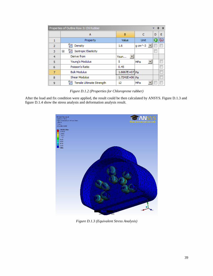
Figure D.1.2 (Properties for Chloroprene rubber)
After the load and fix condition were applied, the result could be then calculated by ANSYS. Figure D.1.3 and
figure D.1.4 show the stress analysis and deformation analysis result.
Figure D.1.3 (Equivalent Stress Analysis)

40
Figure D.1.4 (Total Deformation)
As it could be seen from the figure, the highest stress is about 7 Pa and highest deformation is about 0.0002m.
They are small as the force applied to the friction rollers are relatively small. However, it is still necessary to
conduct such analysis to make sure that the device, especially the rubber part would not suffer huge
deformation, which might affect the performance of the device.

41
Appendix E: Evaluation Reports This section shows the evaluation process for the key design. To evaluate the design, each of the design
requirements should be tested. The following describes on a high-level how each requirement will be tested. In
order to determine the first requirement that the device must push through the skin, theoretical analysis was
used focusing on the needle, friction rollers, and the rotation of each. Size, weight, and portability were
analyzed based on the dimensions of the device using a computer program. Fulfilling another requirement, that
of the device performing quickly, will be theoretically calculated as well. To determine the acceptable suture
quality and ease of operation, the physical prototype needs to be created to test those requirements. Low cost is
determined by the Bill of Materials listed in the appendix.
Criterion 1: Skin Breakage Introduction
The suturing device’s main function is to pass a needle through skin put in place the suture. It was necessary to
investigate the forces needed to pierce the skin and to confirm that our device was capable of doing so.
Method
The researched material properties of skin were used to calculate the needed applied force. Forces needed by
the needle was calculated as it was assumed that less force was needed to pass the suture through (The suture
has a smaller diameter and less friction). Then the maximum friction force that the device could provide was
calculated to compare with the force needed by the needle. After that, the friction force was compared with the
force on the gear which comes from the motor to find out if motor would provide enough force. This would
confirm the evaluation process that the device had the ability to puncture skin.
Force to Pierce Skin
In calculating the forces needed to pierce skin we found it as a sum of 2 forces: The force to puncture (Fp) and
the friction force (FFS) on the needle (Equation E.1.1).
Fpierce = Fp + FFS
Equation E.1.1
Puncture force was calculated by taking the ultimate tensile strength (UTS) and multiplying it by the area of
the needle tip (Atip). This would be the force needed to tear open the skin and allow the needle to pass through.
The UTS was found from a University of College Dublin research to be 21.5MPa (Mechanical Properties of
Human Skin). The needle tip area was calculated using a needle tip diameter of 0.5mm. The following
calculation for Fp was made below.
Fp = UTS ∗ Atip = 21.5 ∗ 106N
m2∗ π ∗ (0.00025m)2 = 1.7N
Equation E.1.2
Next we calculated the frictional force between the skin and the needle to find Ffs. To find the friction force we
needed to know the radial force on the needle from the elasticity of the skin. Once the skin is punctured by the
tip of the needle, it stretches over the diameter of the needle. A UMDJ- Robert Wood Johnson Medical School
study found that the elastic spring constant (ks) of human skin was 18.8MPa. If we multiplied this constant by
the stretched area, we could then find the radial force on the needle (Fr). This force multiplied the coefficient of friction for skin on metal (µs) would give the desired frictional force. The coefficient of friction of metal on
skin was found to be 0.8-1 (Engineering ToolBox Friction Coefficients). The highest value of 1 was used for
worst case.

42
FFS = Frµs = AneedleKsµs =π(0.001m)2
4∗ 18.8 ∗ 106
N
m2∗ (1) = 14.76N
Equation E.1.3
This result revealed that more force is needed for the frictional forces of piercing skin. This left the total
piercing force to be 16.47N using Equation E.1.1. The forces from tangential force and friction force of the
rubber grips would need to be more than this.
Friction Forces Applied to Needle
The next step was to see what forces the rubber heads actually were able to provide. The needle was driven by
the friction force which caused by the deflection of the rubber heads. Figure E.1.1 shows the deflection of the
rubber heads with the needle.
Figure E.1.1 (Deflection of the rubber heads)
Friction force from each connection of needle and rubber heads would be calculated by Equation E.1.4. In
Equation E.1.4, μ is the coefficient of friction for the rubber heads (0.7) and the needle and N is the
perpendicular force from the rubber heads.
FFriction = μ × N
Equation E.1.4
To find the perpendicular force N which was caused by the deflection of the rubber heads, Equation 3 was
used. In Equation E.1.5, x is the deflection of the rubber heads shown in the figure 1 and x0 is the original
diameter of the rubber head. E is elastic modulus of rubber, which is 0.1 GPa. A is the contact surfaces
between the needle and the rubber head. It was assumed as 3 mm2. N was found as 6 N and FFriction was found
as 4.2N.
N = E ∙ A ∙ x/x0
Equation E.1.5
It was also assumed that there were minimum three connections that would contribute the friction forces to the
needle. So the total friction force provided by the rubber heads was found by using Equation E.1.6.
FTotal Friction = FFriction × 6
Equation E.1.6
The FTotal Friction was calculated as 25.2N. After Comparing FTotal Friction with FFS , the conclusion could be
made that the friction force provided by rubber heads is enough to let the needle punch into the skin.
Minimum force assigned to gears
After confirming that the friction force was big enough to drive the needle in the skin, forces assigned to the
gears needed to be calculated to make sure that gears would provide enough friction force. As it could be seen
43
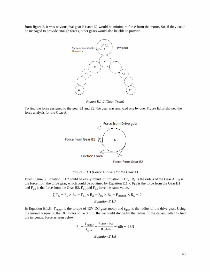
from figure.2, it was obvious that gear E1 and E2 would be minimum force from the motor. So, if they could
be managed to provide enough forces, other gears would also be able to provide.
Figure E.1.2 (Gear Train)
To find the force assigned to the gear E1 and E2, the gear was analyzed one by one. Figure E.1.3 showed the
force analysis for the Gear A.
Figure E.1.3 (Force Analysis for the Gear A)
From Figure 3, Equation E.1.7 could be easily found. In Equation E.1.7, RA is the radius of the Gear A. FD is
the force from the drive gear, which could be obtained by Equation E.1.7. FB1 is the force from the Gear B1
and FB2 is the force from the Gear B2. FB1 and FB2 have the same value.
∑TA = FD × RA − FB1 × RA − FB2 × RA − FFriction × RA = 0
Equation E.1.7
In Equation E.1.8, Tmotor is the torque of 12V DC gear motor and rgear is the radius of the drive gear. Using
the known torque of the DC motor to be 3.3in ∙ lbs we could divide by the radius of the driven roller to find
the tangential force as seen below.
FT =Tmotor
rgear=3.3in ∙ lbs
0.54in= 6lb = 26N
Equation E.1.8
44
Next, the same force analysis for the rest of the gears were made using the same method as the Gear A. After
that, the force applied to the Gear E1 by the Gear D1 was found out as 7 N, which was bigger than FFriction
which proved that the force assigned to each gear is enough to support the rotating of the needle.
Criterion 2: Portability Introduction:
Portability is one design requirement that is fulfilled by having the dimensions of the main body smaller than
that of a single hand. This requirement is important so that the operator can maintain control throughout the
entire procedure. If the device was equal to or of greater size than the main body, the operator would not have
a good grip on the device and therefore, would not make a quality suture. The area cannot be too small either,
otherwise, the same issues would occur; quality would also be at risk just as if it was too large for a hand.
Method:
These requirements were tested within the program, SolidWorks, by ensuring the dimensions were smaller
than the average human hand across genders. The average male hand is 189 mm tall, from the wrist to the
middle fingertip, as the female hand is a height of 172 mm. Therefore, the average is 180.5 mm tall. In order to
test this requirement, the surface area where the hand would hold the device has to be smaller, although not
drastically smaller, than the average human hand length.
Results:
From the device, the measurements are 160 mm around which is less than even an average female hand. This
allows diversity for the type of operator and ensures optimal stability from the hand. Since the hand can wrap
around it as well quite easily, the device should be able to fit in normal drawers, which are 20x17x6 inches.
The length of the total device is about 7 inches, and the height, is 3 inches at the highest point on the device.
The automated suturing device is portable because it can fit in a normal size drawer as well as a human hand
easily. Hence, this requirement is fulfilled.
Also, the weight of the device is going to come into the portability test. Making sure it isn’t beyond what
would be easy to carry around all day is critical; soldiers and first responders are already weighed down with
different tools and materials, so keeping the tool light is important.
On SolidWorks, the volume is 9 in³, the density of the 3D printing material is 0.0376 lb/in³ since it is ABS
plastic. Volume multiplied by density equals mass. Total mass of the 3D printed piece equals 0.3384 lb. Add
that to the motor weight, 0.5 lb, and the head piece, 0.33 lb, to come to a final weight of 1.1 lbs. This is
exceptionally smaller than our design requirement of 5 lbs.
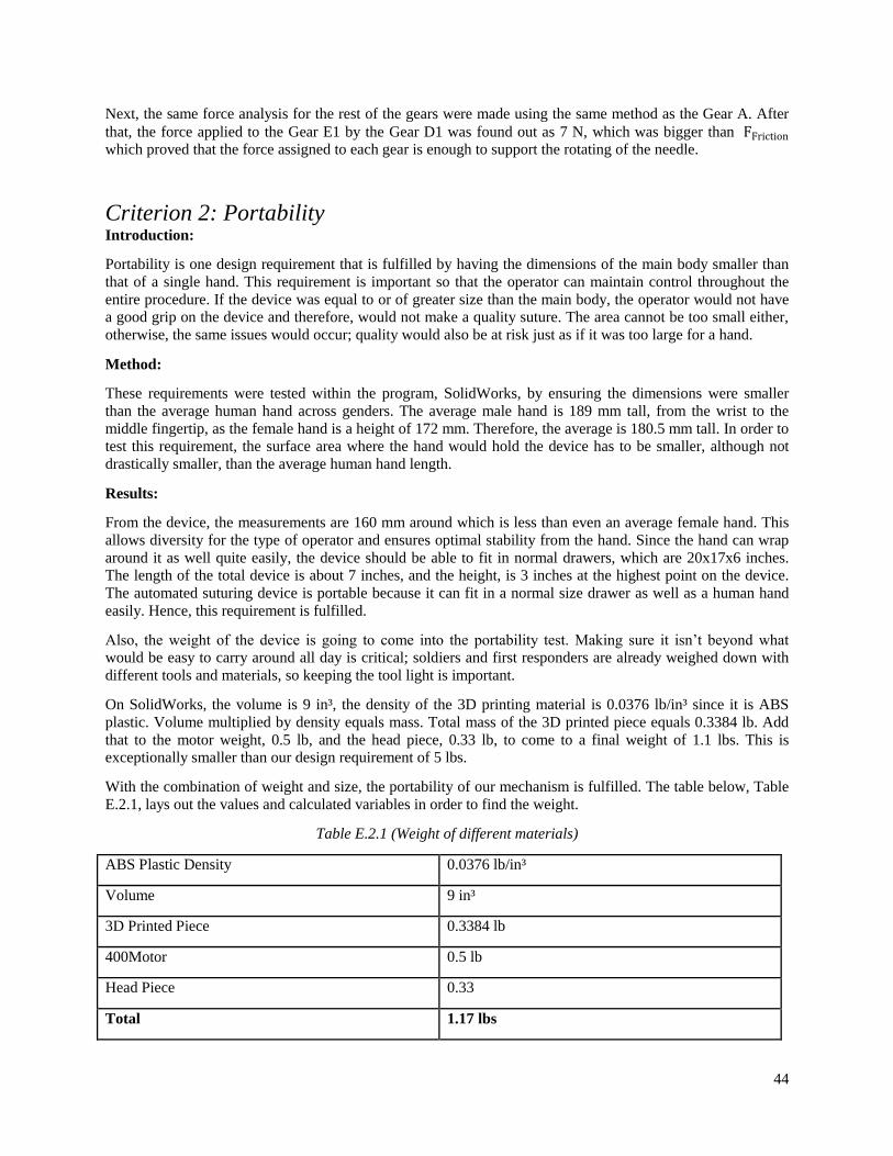
With the combination of weight and size, the portability of our mechanism is fulfilled. The table below, Table
E.2.1, lays out the values and calculated variables in order to find the weight.
Table E.2.1 (Weight of different materials)
ABS Plastic Density 0.0376 lb/in³
Volume 9 in³
3D Printed Piece 0.3384 lb
400Motor 0.5 lb
Head Piece 0.33
Total 1.17 lbs

45
Discussion:
This result proves that this device would be able to be taken anywhere due to its size. This is a major benefit
for the key consumer, as well as those consumers out of scope. Lighter things can be used for a longer time as
well as carried around without much added fatigue. Therefore, when this device is bought, it can be used by a
wide audience and can be placed in bags without a major weight or size issue.
Criterion 3: Time to perform suturing process Introduction:
A very key requirement for the device is to perform suturing quickly and efficiently. If the device does not
suture quicker than conventional hand suturing, the device will not be marketable. To find the time it takes to
suture a wound, dimensions of the needle, and the motor shaft diameter were assumed.
Method:
A needle with a diameter of 1 inch and a 12 volt, dc motor with 200 RPM were used. A gear ratio between the
gear that the motor shaft drove and the diameter of the track that the needle was rotated on was used to find the
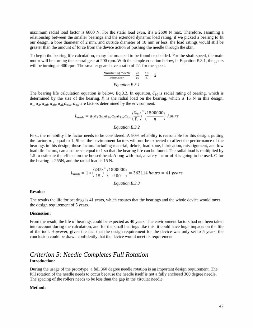
angular velocity of the needle track. The gear ratio equation used can be found in Equation E.3.1. Firstly, the
RPM of the motor was converted to inches/second, then Equation E.3.1 was used to find the angular velocity
of the needle. Once the angular velocity of the needle was found to be 0.58166 in/sec, this value could be
compared to the circumference of the needle, which was calculated by Equation E.3.2, to be 3.14 inches, to
find how long it will take for the needle to do one full rotation.
Equation E.3.1
𝑐𝑖𝑟𝑐𝑢𝑚𝑓𝑒𝑟𝑒𝑛𝑐𝑒 = 2𝜋𝑟 Equation E.3.2
Figure E.3.1 (Gear Dimensions)

46
Figure E.3.2 (Gear Set Up)
Results:
With a motor of 200 RPM, the needle can rotate 360° in approximately 5.4 seconds. Constant velocity, no
friction in the needle track, and a full RPM of 200 were all assumed in this calculation. 5.4 seconds per suture
is a very ideal value and if experimental prototype results show a similar time, this would be preferred. If a cut
of 4 inches was to be sutured by our device, and assuming a suture every ¼ of an inch, this would yield 16
total sutures to stitch up this wound. To make 16 sutures and to close this wound, would ideally take
approximately 86 seconds or just under 3 minutes of procedure.
Discussion:
This result shows a drastic improvement over traditional suturing and this result could increase wound closure
time immensely. If the device could work at this optimum speed, accounting for friction that will be
encountered once the needle enters the skin, this would still show a large improvement in the time it takes to
suture a wound close. There could be some error in suturing when a motor has such high velocity, and this
needs to be addressed carefully before any skin puncture has taken place.
Criterion 4: Device Longevity Introduction:
Finding the life of the device is an important consideration. The device shouldn’t fail when it is needed most,
either from electric or stress fault. Therefore, the focus of this section will be on the most breakable part of the
device, bearings. The bearings that the inside of the balls that link to the permanent piece of the head carry a
radial load from the needle moving through the skin.
Method:
The device longevity focuses on one part of the device- bearings. The bearings are the vulnerability of the life
of this tool due to the motion and the fact that the bearings have bearings on the inside of the holds and also
require to move the needle through the head. Focusing on the bearings, using mechanical analysis and solving
for the bearing stress and life, will give a good indication of the longevity of this device.
In order to begin the analysis of the bearings, one major thing needs to be assumed: since we do not have
access to reliable tables other than those provided in past courses, a bearing size which we need can be similar
to the type we choose. In this case, a simple ball bearing is needed, since the radial load will be much greater
than any axial load the bearing will face. Therefore, the dynamic equivalent radial load factor will be equal to
the radial load. The smallest bore diameter is the one we can analyze. Bearing 200K, from Timken Products
Catalog, the light 200K series table, provides a bore diameter of 10 mm, and a width of 9 mm.
The radial load was calculated from the force required to break the skin, about 15 N maximum, so the total
dynamic equivalent radial load factor is equal to that as well. For the bearing that we chose, 200K, the
47
maximum radial load factor is 6800 N. For the static load even, it’s a 2600 N max. Therefore, assuming a
relationship between the smaller bearings and the extended dynamic load rating, if we picked a bearing to fit
our design, a bore diameter of 2 mm, and outside diameter of 10 mm or less, the load ratings would still be
greater than the amount of force from the device action of pushing the needle through the skin.
To begin the bearing life calculation, many factors need to be found or decided. For the shaft speed, the main
motor will be turning the central gear at 200 rpm. With the simple equation below, in Equation E.3.1, the gears
will be turning at 400 rpm. The smaller gears have a ratio of 2:1 for the speed.
𝑁𝑢𝑚𝑏𝑒𝑟 𝑜𝑓 𝑇𝑒𝑒𝑡ℎ
𝐷𝑖𝑎𝑚𝑒𝑡𝑒𝑟=
20
10=
10
5= 2
Equation E.3.1
The bearing life calculation equation is below, Eq.3.2. In equation, 𝐶90 is radial rating of bearing, which is
determined by the size of the bearing. 𝑃𝑟 is the radial load on the bearing, which is 15 N in this design.
𝑎1, 𝑎2, 𝑎3𝑑 , 𝑎3𝑘 , 𝑎3𝑙,𝑎3𝑚, 𝑎3𝑝 are factors determined by the environment.
𝐿𝑛𝑚ℎ = 𝑎1𝑎2𝑎3𝑑𝑎3𝑘𝑎3𝑙𝑎3𝑚𝑎3𝑝 (𝐶90
𝑃𝑟)
3
(1500000
𝑛) ℎ𝑜𝑢𝑟𝑠
Equation E.3.2
First, the reliability life factor needs to be considered. A 90% reliability is reasonable for this design, putting
the factor, 𝑎1, equal to 1. Since the environment factors will not be expected to affect the performance of the
bearings in this design, those factors including material, debris, load zone, lubrication, misalignment, and low
load life factors, can also be set equal to 1 so that the bearing life can be found. The radial load is multiplied by
1.5 to estimate the effects on the housed head. Along with that, a safety factor of 4 is going to be used. C for
the bearing is 255N, and the radial load is 15 N.
𝐿𝑛𝑚ℎ = 1 ∗ (245
15)
3
(1500000
400) = 363114 ℎ𝑜𝑢𝑟𝑠 = 41 𝑦𝑒𝑎𝑟𝑠
Equation E.3.3
Results:
The results the life for bearings is 41 years, which ensures that the bearings and the whole device would meet
the design requirement of 5 years.
Discussion:
From the result, the life of bearings could be expected as 40 years. The environment factors had not been taken
into account during the calculation, and for the small bearings like this, it could have huge impacts on the life
of the tool. However, given the fact that the design requirement for the device was only set to 5 years, the
conclusion could be drawn confidently that the device would meet its requirement.
Criterion 5: Needle Completes Full Rotation Introduction:
During the usage of the prototype, a full 360 degree needle rotation is an important design requirement. The
full rotation of the needle needs to occur because the needle itself is not a fully enclosed 360 degree needle.
The spacing of the rollers needs to be less than the gap in the circular needle.
Method:
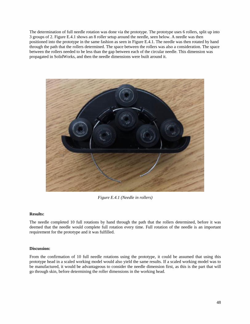
48
The determination of full needle rotation was done via the prototype. The prototype uses 6 rollers, split up into
3 groups of 2. Figure E.4.1 shows an 8 roller setup around the needle, seen below. A needle was then
positioned into the prototype in the same fashion as seen in Figure E.4.1. The needle was then rotated by hand
through the path that the rollers determined. The space between the rollers was also a consideration. The space
between the rollers needed to be less than the gap between each of the circular needle. This dimension was
propagated in SolidWorks, and then the needle dimensions were built around it.
Figure E.4.1 (Needle in rollers)
Results:
The needle completed 10 full rotations by hand through the path that the rollers determined, before it was
deemed that the needle would complete full rotation every time. Full rotation of the needle is an important
requirement for the prototype and it was fulfilled.
Discussion:
From the confirmation of 10 full needle rotations using the prototype, it could be assumed that using this
prototype head in a scaled working model would also yield the same results. If a scaled working model was to
be manufactured, it would be advantageous to consider the needle dimension first, as this is the part that will
go through skin, before determining the roller dimensions in the working head.

49
Appendix F: Cost Analysis Table F.1 shows the bill material for prototype and table F.2 shows the bill material of the estimation of the
product cost. As it could be shown in the table F.1 and table F.2, the total cost for both prototype and actual
product would meet the design requirement.
Table F.1 Bill of Materials for Prototype
Item Description Manufacturer Model Quantity
required
Unit price Total price
Bearings OD 1/8’’ McMaster 6383K32 6 $30 $180
Needle Custom made - - 1 $9.99 $9.99
Working
Head
3D printing $48 $48
Model
Head
3D printing - - 1 $24 $24
Handle 3D printing - - 1 $56 $56
Total 317.99
Table F.2 Bill of Materials for Produce
Item Description Manufacturer Model Quantity
required
Unit price Total price
12V motor 12 V DC gear
motor
Hossen B00BX9KUA
M
1 $9.34 $9.34
Gears1 OD 0.29’’ McMASTER-
CARR
7880K17 10 $10.41 $104.10
Gears2 OD 0.35’’ McMASTER-
CARR
7880K18 3 $11.27 $33.81
Gears3 OD 0.54’’ McMASTER-
CARR
7880K21 1 $14.43 $14.43
Removable
Casing
Injection
molding
- - 1 $3 $3
Suture barbed suture Quill - 1 $8 $8
Handle Injection
molding
- - 1 $3 $3
Switch - McMaster 23423 1 $1.01 $1.01
Bearings OD 1/4’’ McMaster 6384K342 28 $5.32 $148.96
Rubber
heads
Injection
molding
- - 10 $0.4 $4
Battery 12 Volt Energizer A23 2 $1.5 $3
Total $324.56

50
Appendix G: Failure Modes and Effect Analysis

51
Appendix H: Environmental Impact Purpose and need
The objective of this project is to create a device that allows medical professionals and military personnel to
easily close a wound in an efficient manner. A device that accomplishes a clean and efficient stitching is
advantageous in delaying the onset of tissue necrosis and keeping the wound uninfected. Such situations
include military use as well as first responder use in rural areas that are far removed from available health care.
This device could be developed for the main purpose of improved health care by introducing an easier solution
for suturing practices. It would be of great benefit for society.
Impact to environment
As a medical device, its environment impact is almost unavoidable as disposable part has to be implemented to
avoid contamination. However, as part of the design goals, efforts were made to minimize the pollution.
During the production process, since most parts of the device would be made by injection molding, toxic gas
generated during the molding process could be a major concern. When clients use the device, they have to
change the working head, which includes needle and guide after every operation. Those disposable parts are
harmful for the environment. At the end-life of the device, most parts such as plastic, battery, motor could be
recycled. But parts like switch and roller are not easy to be recycled as they contain different materials.
Alternatives to design
One alternative to the design is to make use of solar energy. The reason this was chosen was because solar
energy is a matured form of alternative energy and could be implemented rather easily on this design. Also in
certain conditions, users might not have access to charge the device and solar energy could be used as a backup
source of charge. As far as the environment is concerned, solar energy is clean and cause no pollution during
use.
Discussion
In the alternative design, making use of solar energy would definitely reduce impact for the environment.
However, one of the questions it has is increasing cost of the device. Since the target customers for the device
are not likely to afford expensive equipment, the alternative design might largely reduce the device’ target
market. For the future, more environmental friendly materials could be added into the device to reduce its
environmental impact.

52
Appendix I: Codes, Standards and Safety When considering the design of a medical device, there are obvious safety regulations that must be considered.
Medical device regulations have the capability of slowing down production of a device, and the production of
this automated suturing device is time sensitive due to other products on the market that are also completing a
similar task. To stay in accordance with these regulations and codes, the U.S. Food and Drug Administration
was used as a guide. The FDA is very extensive in its regulations, especially in reference to medical devices.
As with most medical devices, this automated suturing device can be classified under Title 21 of the Code of
Federal Regulations. More specifically this device can be classified under Regulation Citation part 878,
general and plastic surgery. This classification part has most suture related devices classified. This automated
suturing device could also be considered a 510(k), as it could be a premarket submission to the FDA to prove
that this device is at least as safe and effective, to a legally marketed device.
As it is important for any medical device to be used properly, it is no different for the automated suturing
device. Medical professionals with suturing experience should be a first priority to use this device. Medical
professionals should take the consideration of the patient’s pain tolerance during the suturing procedure, and
plan to limit pain using a local anesthetic. The purpose of the design of this automated suturing device was to
limit the risk for user error, or harm that could be inflicted to the user, such as needle stick. The protective
needle casing that surrounds the needle limits needle exposure time to a short period.

53
Appendix J: Patent Search Objectives:
A patent search is needed in the development of our design to ensure no patent infringement is encountered, as
well as comparing patented medical devices to the potential patentable device that is being prototyped. A
patent search is also helpful in idea generation. Looking at devices that are similar to the device that is being
developed, can cause idea generation and insight. In the design of the automated suturing that is being
developed, the most patentable area of the device is the head. In the head, a gear train assembly is controlled
by a main top gear that is rotated by the motor shaft. The gears are directly connected to rubber friction rollers
that handle the needle. The friction rollers have a slit in them where the needle will by passed through. The
rollers use frictional forces between the two to pass the needle and provide enough rotational force on the
needle to puncture skin. The head can be seen in Figure J.1.
Figure J.1 (Friction Roller Arrangement with Gear Train)
Search Criteria:
Patents were located from Google Patents as well as from the product’s website directly, as in the case of the
Sutrue; which was found on WIPO, international and national patent collections. Patents were found using
keywords such as suturing device, automated suturing device, automatic needle rotation, rotating suturing
device, automated medical device, suture, rotating needle.
Findings:
The most relatable patents to this device were found to be patents that involved rotational suturing motion in
their design.
(Figure J.2) Automated Helical Needle: This patent was found using Google Patents. This patent was useful
because it showed that a rotational needle device could in fact be manufactured. This patent posed no major
threat to the automated suturing device that was developed, but in fact showed how to rotate a needle in a

54
dimensioned space. A client could use this patent as a relation to the device developed since they both
incorporate a rotational needle mechanism.
(Figure J.3) Sutrue: This patent was found from the Sutrue website. This patent is the most similar to the
automated suturing device that was developed for this senior design class. Sutrue has several similar aspects to
the device prototyped. The device uses barbed sutures, while the Sutrue uses traditional sutures, thus needing
to tie knots. The device has a replaceable track shield, while the Sutrue has a replaceable head entirely. The
exact dimensions of the needle in the device are not known currently, while the curvature of the needle used in
the Sutrue is between 270 degrees and 360 degrees. Both devices will use roller technology to advance the
needle rotationally, as it is the best mode of doing so. A client would find similarities in the aesthetics of each
device, and find similarities in the roller technology in each devices. The usage of barbed sutures as well as a
friction roller technology adds quicker suturing rates to the developed device. The Sutrue could hold some
small threat to the patentability to the device that was designed in the shape of the design and in the roller
technology.
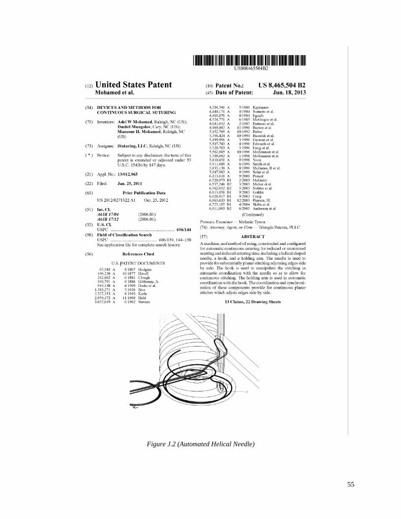
55
Figure J.2 (Automated Helical Needle)

56
Figure J.3 (Sutrue)