final year ppt2013
TRANSCRIPT
By
Jawad Ur Rasool
Fazal ur Rehman
M.Nasir Yousaf
Project Supervisor:
Engr . Hamayun Aziz Khan

Agenda
To make a small prototype of Water Supply System that can be
implemented in the real industry with a few modifications , to
automate the old traditional water supply system in Pakistan
so that there would be minimum human involvement and
maximum automation.
Introduction
Equipment
Hardware
Software
Scope of the project
Fundamentals of the project
Physical layout of the project
Equipment used in project (Field Instruments)
Hardware implemented
Elements of hardware essential for water supply
system
Software implemented
Elements of Software essential for water supply
system (SCADA and programming)
Scope of the project..
Introduction
The aim of this project is to design a PLC Based Water
Supplying System that monitors the water distribution among
the different areas of a locality; through a centralized remote
Location. “Scada and PLC based water supply system”
consists of two parts; one is control and Second is monitoring
part. The major part of control will be performed by a controller
in our case it is PLC and Updates particular outputs (related to
inputs) to perform the desired operation which can be switching
of motors, switching alarms, maintaining water levels e.t.c. The
Monitoring part will be performed by Indu Soft (SCADA)
software.

Flow Diagram

Distribution Unit
Sector 1Sector2Output
Input
SCADA
Main Water
Stream
Underground
Tank
PLC
Overhead Tank

Physical Appearance
Objectives
We aimed to build the prototype of such control automation that will meet the requirements of modern water supply system. PLC will be introduced to give perfect automation. The main reasons of selecting this project is to have monitoring plus control the every stage of water supply system from a centralized location and also to minimize the number of labor cost required for troubleshooting and service by giving it automatic control.
Future Scope of project
The current water supply systems in Pakistan are old and traditional systems in which there is more labor cost, wastage of water and these are un-reliable systems, but SCADA & PLC based water supply system will take over these issues in such a way that it saves time and money by eliminating the need for service personals to visit each site for inspection, data collection or adjustment, it provides real time monitoring and troubleshooting, automatic report generation, immediate knowledge of system performance. This is a pure industrial project and its scope is huge mainly in water supplying departments, water purification plants, boilers and in every field where we have to supply water or any other liquid (off course with some modifications). For example in Pakistan this system can be very useful for WASA (Water and Sanitation Agency), DWM (Department of Water Management) NWFP & CDA etc.

Equipment
A programmable logic controller (PLC) or programmable controller is a digital computer used for automation of electromechanical processes, such as control of machinery on factory assembly lines, amusement rides, or light fixtures, water supplying systems and many more such industrial processes. PLCs are used in many industries and machines. Unlike general-purpose computers, the PLC is designed for multiple inputs and output arrangements, extended temperature ranges, immunity to electrical noise, and resistance to vibration and impact.
PLC
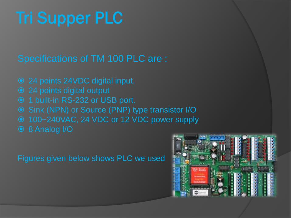
Tri Supper PLC
Specifications of TM 100 PLC are :
24 points 24VDC digital input.
24 points digital output
1 built-in RS-232 or USB port.
Sink (NPN) or Source (PNP) type transistor I/O
100~240VAC, 24 VDC or 12 VDC power supply
8 Analog I/O
Figures given below shows PLC we used

Field Instruments
Instruments are the equipment (sensors , motors , pumps etc) installed in
the field near the system that send data (input) to the PLC and PLC act
according to this received data. Field instruments gather all the
information of the system and send this to PLC in the form of either
Analogue or Digital inputs. These field instruments could be sensors,
motors, pumps etc. In our project the field instruments are:
Level Detectors:
Level Detectors are used to sense the level of liquid (water in our case). For
this purpose different types of detectors are used that can be digital and
analogue.
ROD Sensors:
Rod sensors are used to
determine the water level in
The tank and it is also
Implemented in the project.
Water Pump
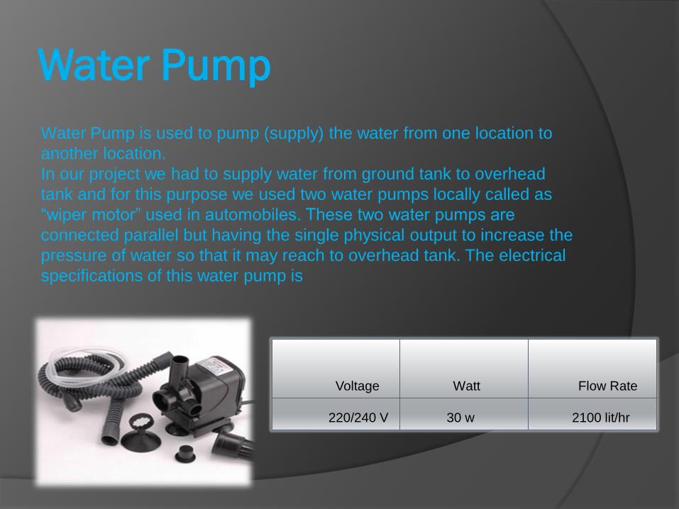
Water Pump is used to pump (supply) the water from one location to
another location.
In our project we had to supply water from ground tank to overhead
tank and for this purpose we used two water pumps locally called as
“wiper motor” used in automobiles. These two water pumps are
connected parallel but having the single physical output to increase the
pressure of water so that it may reach to overhead tank. The electrical
specifications of this water pump is
Voltage Watt Flow Rate
220/240 V 30 w 2100 lit/hr
Solenoid Valve
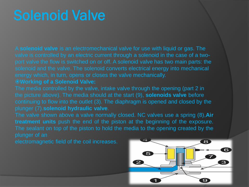
A solenoid valve is an electromechanical valve for use with liquid or gas. The
valve is controlled by an electric current through a solenoid in the case of a two-
port valve the flow is switched on or off. A solenoid valve has two main parts: the
solenoid and the valve. The solenoid converts electrical energy into mechanical
energy which, in turn, opens or closes the valve mechanically.
Working of a Solenoid Valve:
The media controlled by the valve, intake valve through the opening (part 2 in
the picture above). The media should at the start (9), solenoids valve before
continuing to flow into the outlet (3). The diaphragm is opened and closed by the
plunger (7).solenoid hydraulic valve.
The valve shown above a valve normally closed. NC valves use a spring (8),Air
treatment units push the end of the piston at the beginning of the exposure.
The sealant on top of the piston to hold the media to the opening created by the
plunger of an
electromagnetic field of the coil increases.

Solenoid Valves
We used two Solenoid Valves shown below to supply water from
overhead tank to two different locations.
Specifications of Solenoid Valves:
Voltage (A.C) Orifice Pipe Size Pressure
(Max.)
Temperature
220V/110V 16 mm 1/2" 10 kg/cm² -5 ºC----85 ºC
Hardware
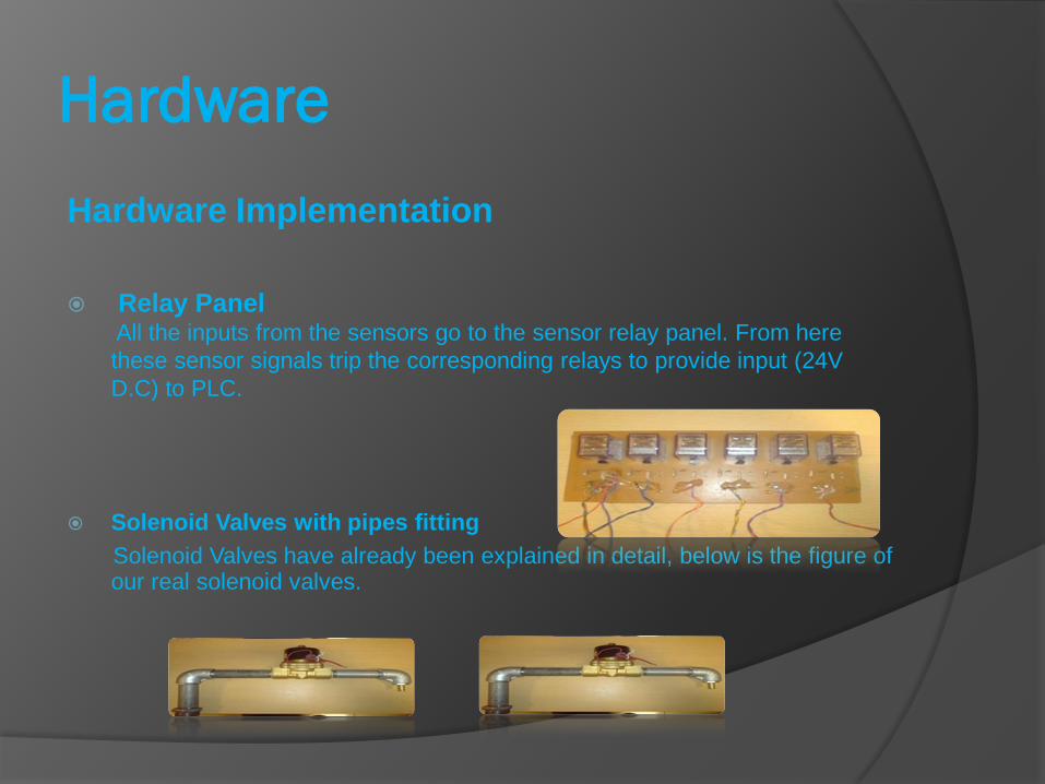
Hardware Implementation
Relay PanelAll the inputs from the sensors go to the sensor relay panel. From here
these sensor signals trip the corresponding relays to provide input (24V
D.C) to PLC.
Solenoid Valves with pipes fitting
Solenoid Valves have already been explained in detail, below is the figure of our real solenoid valves.
Hardware Implementation
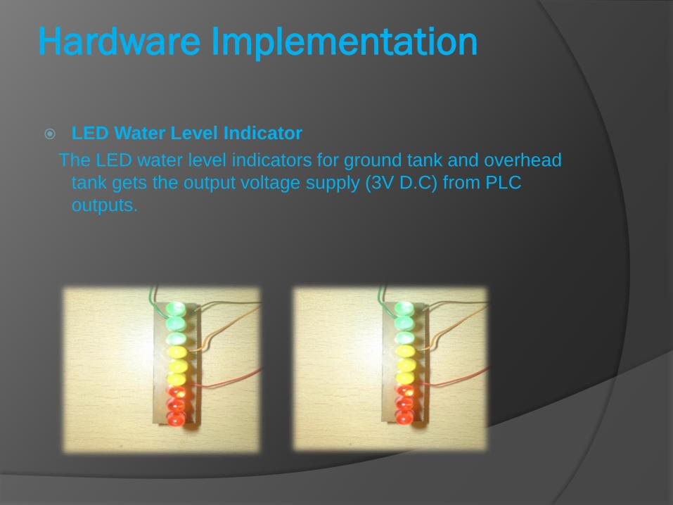
LED Water Level Indicator
The LED water level indicators for ground tank and overhead
tank gets the output voltage supply (3V D.C) from PLC
outputs.

Control Panel
A manual control panel has been introduced to control the system manually
Emergency Stop Button: This button has been
introduced to protect the whole system and
human lives in case of emergency. So that our
whole system would be shut down with a single
button.
Auto / Manual Switch: This knob is used to make
our system fully automatic or manual when
require.
Three Buttons: To ON / OFF solenoid vales
these switches are used.
One Toggle Switch To ON / OFF the water pumps
LED Indicator: To show the water levels in the
tanks LED water level indicator have been
introduced.
Water Tanks
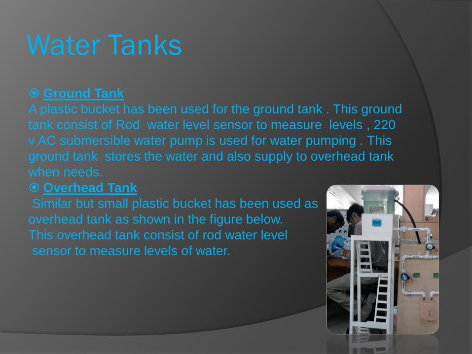
Ground Tank
A plastic bucket has been used for the ground tank . This ground
tank consist of Rod water level sensor to measure levels , 220
v AC submersible water pump is used for water pumping . This
ground tank stores the water and also supply to overhead tank
when needs.
Overhead Tank
Similar but small plastic bucket has been used as
overhead tank as shown in the figure below.
This overhead tank consist of rod water level
sensor to measure levels of water.
Final Software Implementation
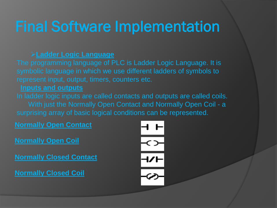
Ladder Logic Language
The programming language of PLC is Ladder Logic Language. It is
symbolic language in which we use different ladders of symbols to
represent input, output, timers, counters etc.
Inputs and outputs
In ladder logic inputs are called contacts and outputs are called coils.
With just the Normally Open Contact and Normally Open Coil - a
surprising array of basic logical conditions can be represented.
Normally Open Contact
Normally Open Coil
Normally Closed Contact
Normally Closed Coil
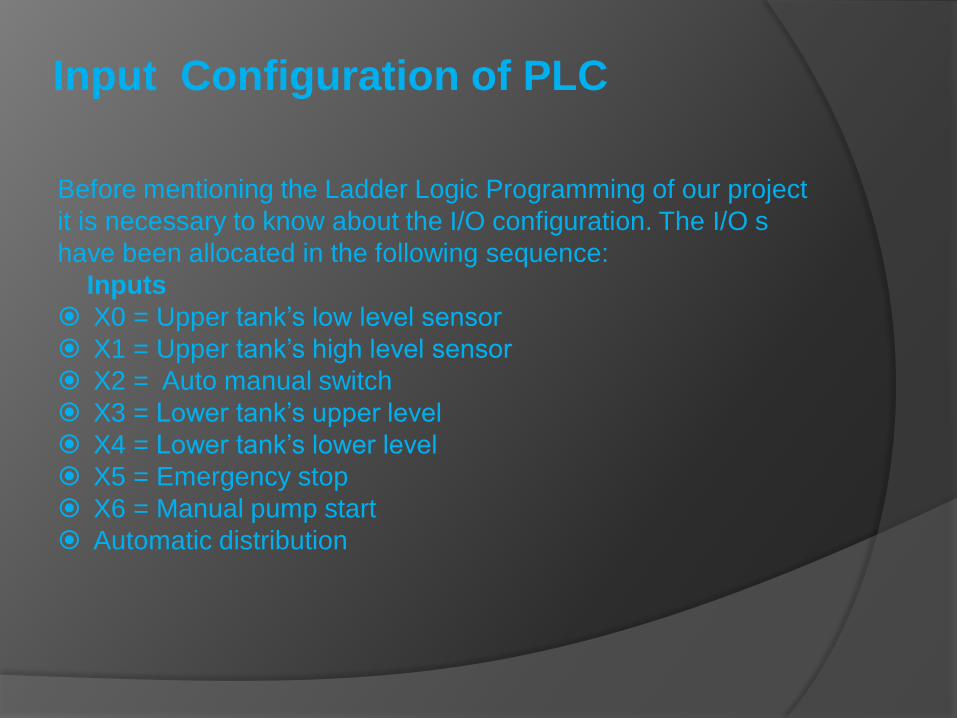
Input Configuration of PLC
Before mentioning the Ladder Logic Programming of our project
it is necessary to know about the I/O configuration. The I/O s
have been allocated in the following sequence:
Inputs
X0 = Upper tank’s low level sensor
X1 = Upper tank’s high level sensor
X2 = Auto manual switch
X3 = Lower tank’s upper level
X4 = Lower tank’s lower level
X5 = Emergency stop
X6 = Manual pump start
Automatic distribution
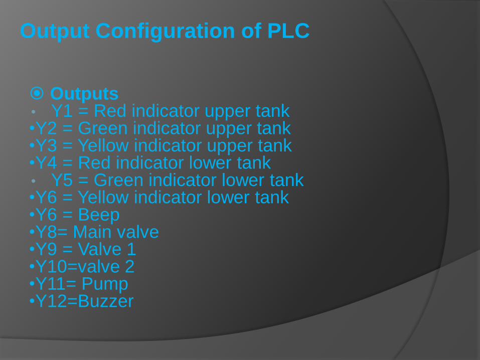
Output Configuration of PLC
Outputs• Y1 = Red indicator upper tank•Y2 = Green indicator upper tank•Y3 = Yellow indicator upper tank•Y4 = Red indicator lower tank• Y5 = Green indicator lower tank•Y6 = Yellow indicator lower tank•Y6 = Beep•Y8= Main valve•Y9 = Valve 1•Y10=valve 2•Y11= Pump•Y12=Buzzer
Ladder Logic


SCADA Implementation Acronym for Supervisory Control And Data
Acquisition, a computer system for gathering and
analyzing real time data. SCADA systems are
used to monitor and control a plant or equipment
in industries such as telecommunications, water
and waste control, energy, oil and gas refining and
transportation. In our project SCADA performs vital
role to monitor and control the system.

SCADA Components
A SCADA system usually consists of the following subsystems:•A human–machine interface or HMI is the apparatus whichpresents process data to a human operator, andthrough this, the human operator monitors and controls theprocess.•A supervisory (computer) system, gathering (acquiring) data onthe process and sending commands (control) to the process.•Remote terminal units (RTUs) connecting to sensors in theprocess, converting sensor signals to digital data and sendingdigital data to the supervisory system.•Master Terminal Unit (MTU)•Programmable logic controller (PLCs) used as field devicesbecause they are more economical, versatile, flexible, andconfigurable than special-purpose RTUs.•Communication infrastructure connecting the supervisorysystem to the remote terminal units.•Various process and analytical instrumentation

SCADA Implementation
SCADA system could be implemented through
following three layers:

In Our Project
SCADA
PLC
SENSORS
The screen shots of our SCADA
Implementation

Prepared Hardware

THANKS