final request for proposals - connect ncdot
TRANSCRIPT

-- STATE OF NORTH CAROLINA-- DEPARTMENT OF TRANSPORTATION
RALEIGH, N.C.
FINAL REQUEST FOR PROPOSALS
Including Addendum #1 and Addendum #2
DESIGN-BUILD PROJECT
TIP B-2500
June 7, 2011
VOID FOR BIDDING DATE AND TIME OF TECHNICAL AND PRICE PROPOSAL SUBMISSION: July 1, 2011 BY 4:00 PM DATE AND TIME OF PRICE PROPOSAL OPENING: July 19, 2011 AT 2:00 PM CONTRACT ID: C 202185 WBS ELEMENT NO. 32635.1.4 and 32635.3.GV3 FEDERAL-AID NO. BRNHF-0012 (48) and BRNHF-0012(36)
COUNTY: Dare ROUTE NO. NC 12 MILES: 3.68 LOCATION: NC 12 – Replacement of Herbert C. Bonner Bridge across Oregon
Inlet from Bodie Island to Hatteras Island TYPE OF WORK: DESIGN-BUILD AS SPECIFIED IN THE SCOPE OF WORK
CONTAINED IN THE REQUEST FOR PROPOSALS NOTICE: ALL PROPOSERS SHALL COMPLY WITH ALL APPLICABLE LAWS REGULATING THE PRACTICE OF GENERAL CONTRACTING AS CONTAINED IN CHAPTER 87 OF THE GENERAL STATUTES OF NORTH CAROLINA WHICH REQUIRES THE PROPOSER TO BE LICENSED BY THE N.C. LICENSING BOARD FOR CONTRACTORS WHEN BIDDING ON ANY NON-FEDERAL AID PROJECT WHERE THE BID IS $30,000 OR MORE, EXCEPT FOR CERTAIN SPECIALTY WORK AS DETERMINED BY THE LICENSING BOARD. PROPOSERS SHALL ALSO COMPLY WITH ALL OTHER APPLICABLE LAWS REGULATING THE PRACTICES OF ELECTRICAL, PLUMBING, HEATING AND AIR CONDITIONING AND REFRIGERATION CONTRACTING AS CONTAINED IN CHAPTER 87 OF THE GENERAL STATUTES OF NORTH CAROLINA. NOT WITHSTANDING THESE LIMITATIONS ON BIDDING, THE PROPOSER WHO IS AWARDED ANY PROJECT SHALL COMPLY WITH CHAPTER 87 OF THE GENERAL STATUTES OF NORTH CAROLINA FOR LICENSING REQUIREMENTS WITHIN 60 CALENDAR DAYS OF BID OPENING, REGARDLESS OF FUNDING SOURCES. ___________ 5% BID BOND OR BID DEPOSIT REQUIRED ___________

PROPOSAL FORM FOR THE CONSTRUCTION OF CONTRACT NO. C 202185
IN DARE COUNTY, NORTH CAROLINA
Date_________________________ 20_________
DEPARTMENT OF TRANSPORTATION,
RALEIGH, NORTH CAROLINA
The Design-Build Team herein acknowledges that it has carefully examined the location of the proposed work to be known as Contract No. C 202185; has carefully examined the Final Request for Proposals (RFP) and all addendums thereto, specifications, special provisions, the form of contract, and the forms of contract payment bond and contract performance bonds, which are acknowledged to be part of the Contract; and thoroughly understands the stipulations, requirements and provisions. The undersigned Design-Build Team agrees to be bound upon their execution of the Contract and including any subsequent award to them by the Board of Transportation in accordance with this Contract to provide the necessary contract payment bond and contract performance bond within fourteen calendar days after the written notice of award is received by them.
The undersigned Design-Build Team further agrees to provide all necessary materials, machinery, implements, appliances, tools, labor, and other means of construction, except as otherwise noted, to perform all the work and required labor to design, construct and complete all the work necessary for State Highway Contract No. C 202185 in Dare County by no later than the dates(s) specified in the Final RFP or Technical Proposal, whichever is earlier, and in accordance with the requirements of the Engineer, the Final RFP and Addenda thereto, the 2006 Standard Specifications for Roads and Structures, specifications prepared by the Department, the Technical Proposal prepared by the Design-Build Team, at the lump sum price(s) bid by the Design-Build Team in their Price Proposal.
The Design-Build Team shall provide signed and sealed documents prepared by the Design-Build Team, which specifications and plans show the details covering this project and adhere to the items noted above.
The Design-Build Team acknowledges that project documents furnished by the Department are preliminary and provided solely to assist the Design-Build Team in the development of the project design. Unless otherwise noted herein, the Department does not warrant or guarantee the sufficiency or accuracy of any information furnished by the Department.
The Department does not warrant or guarantee the sufficiency or accuracy of any investigations made, nor the interpretations made or opinions of the Department as to the type of materials and conditions to be encountered at the project site. The Design-Build Team is advised to make such independent investigations, as they deem necessary to satisfy their self as to conditions to be encountered on this project. The Design-Build Team shall have no claim for additional compensation or for an extension of contract time for any reason resulting from the actual conditions encountered at the site differing from those indicated in any of the information or documents furnished by the Department except as may be allowed under the provisions of the Standard Specifications.
Although the Department has furnished preliminary designs for this project, unless otherwise noted herein, the Design-Build Team shall assume full responsibility, including liability, for the

project design, including the use of portions of the Department design, modification of suchdesign, or other designs as may be submitted by the Design-Build Team.
The Design-Build Team shall be fully and totally responsible for the accuracy and completenessof all work performed under this contract, and shall indemnify and hold the Department harmlessfor any additional costs and all claims against the Department or the State which may arise dueto errors or omissions of the Department in furnishing the preliminary project designs andinformation, and of the Design-Build Team in performing the work.
The published volume entitled North Carolina Department of Transportation, Raleigh, StandardSpecifications for Roads and Structures, JULY 2006, as well as, all design manuals, policy andprocedures manuals, and AASHTO publications and guidelines referenced in the Request ForProposals, with all amendments and supplements thereto, are by reference, incorporated andmade part of this contract; that, except as herein modified, all the design, construction andConstruction Engineering Inspection included in this contract is to be done in accordance withthe documents noted above and under the direction of the Engineer.
If the Design-Build Proposal is accepted and the award is made, the Technical Proposalsubmitted by the Design-Build Team is by reference, incorporated and made part of this contract.The contract is valid only when signed either by the Contract Officer or such other person asmay be designated by the Secretary to sign for the Department of Transportation. The conditionsand provisions herein cannot be changed except by written approval as allowed by the Requestfor Proposals.
Accompanying the Design-Build Proposal shall be a bid bond secured by a corporate surety, orcertified check payable to the order of the Department of Transportation, for five percent of thetotal bid price, which deposit is to be forfeited as liquidated damages in case this bid is acceptedand the Design-Build Team shall fail to provide the required payment and performance bondswith the Department of Transportation, under the condition of this proposal, within 14 calendardays after the written notice of award is received by them, as provided in the StandardSpecifications; otherwise said deposit will be returned to the Design-Build Team.
Transportation ProgramManagement Director

C 202185 (B-2500) Table of Contents Dare County
TABLE OF CONTENTS COVER SHEET PROPOSAL SHEETS PROJECT SPECIAL PROVISIONS (GREEN SHEETS) PAGE NO. Contract Time and Liquidated Damages .............................................................1 Notice to Proceed.................................................................................................1 Termination of Contract.......................................................................................2 Other Liquidated Damages and Incentives ..........................................................3 Dedicated Multi-Use Path Alternate Bid .............................................................3 Progress Schedule ................................................................................................4 Payout Schedule...................................................................................................5 Mobilization.........................................................................................................6 Substantial Completion........................................................................................6 Submittal of Quantities, Fuel Base Index Price and Opt-Out Option..................7 Construction Access and Staging.........................................................................8 Individual Meetings with Proposers ....................................................................10 Partnering.............................................................................................................10 Execution of Bid, Non-Collusion Affidavit, Debarment and Gift Ban Cert. ......11 Submission of Design-Build Proposal .................................................................12 Alternative Technical Concepts and Confidential Questions ..............................12 Value Analysis .....................................................................................................17 Schedule of Estimated Completion Progress.......................................................17 Revision to FHWA-1273 Concerning Personal Information on Payroll Submissions .. 18 Disadvantaged Business Enterprise .....................................................................18 Certification for Federal-Aid Contracts ...............................................................28 Contractor’s License Requirements.....................................................................29 U. S. Department of Transportation Hotline........................................................29 Subsurface Information........................................................................................29 Bid Documentation ..............................................................................................29 Twelve Month Guarantee ....................................................................................33 Clearing and Grubbing.........................................................................................33 SHPO Documentation for Borrow / Waste Sites.................................................34 Erosion & Sediment Control / Stormwater Certification.....................................35 Procedure for Monitoring Borrow Pit Discharge.................................................40 Culvert Pipe ........................................................................................................42 Drainage Pipe ......................................................................................................43 Pipe Installation and Pipe Culverts .....................................................................44 Cement and Lime Stabilization of Sub-Grade Soils ............................................50 Price Adjustments for Asphalt Binder .................................................................54 Price Adjustments - Asphalt Concrete Plant Mix ................................................54 Field Office ..........................................................................................................55 Mass Concrete......................................................................................................57

C 202185 (B-2500) Table of Contents Dare County
Corrosion Protection Plan ....................................................................................60 Precast Segmental Bridge Construction...............................................................60 Epoxy Jointing of Precast Segments....................................................................80 Post Tensioning....................................................................................................88 Post Tensioning Grout .........................................................................................126 Quality Management............................................................................................130 GENERAL (GREEN SHEETS) ...............................................................................138 SCOPES OF WORK (GREEN SHEETS)
Roadway ..............................................................................................................154 Pavement Management........................................................................................159 Structures .............................................................................................................160 Geotechnical Engineering....................................................................................171 Hydraulics ............................................................................................................183 Signing .................................................................................................................186 Traffic Management.............................................................................................188 Pavement Markings .............................................................................................199 Utilities Coordination...........................................................................................200 Intelligent Transportation Systems ......................................................................207 Erosion and Sedimentation Control .....................................................................211 Environmental Permits.........................................................................................217 Public Information ...............................................................................................228 STANDARD SPECIAL PROVISIONS (YELLOW SHEETS) Liability Insurance ...............................................................................................230 Plant and Pest Quarantines...................................................................................231 Contractor Claim Submittal Form .......................................................................231 Gifts from Vendors and Contractors ...................................................................232 Embankments.......................................................................................................232 Flowable Fill ........................................................................................................233 Bridge Approach Fills..........................................................................................233 Fine Grading Subgrade, Shoulders, and Ditches .................................................235 Aggregate for Soil-Cement Base .........................................................................235 Asphalt Pavements – Superpave..........................................................................236 Asphalt Pavements – Warm Mix Asphalt Superpave..........................................252 Asphalt Binder Content of Asphalt Plant Mixes .................................................254 Asphalt Plant Mixtures .......................................................................................255 Bridge Deck Rideability and Grooving ..............................................................255 Subsurface Drainage ............................................................................................257 Guardrail Anchor Units, Type 350 ......................................................................258 Street Signs and Markers and Route Markers......................................................259 Steel U-Channel Posts and Steel Square Tube Supports .....................................260 Galvanized High Strength Bolts, Nuts and Washers ...........................................260

C 202185 (B-2500) Table of Contents Dare County
Galvanizing ..........................................................................................................261 Aggregate Production ..........................................................................................261 Concrete Brick and Block Production .................................................................261 Portland Cement Concrete (Alkali-Silica Reaction)............................................261 Water for Concrete...............................................................................................262 Glass Beads..........................................................................................................263 Engineering Fabrics .............................................................................................264 Qualification of Welds and Procedures ...............................................................265 Paint Sampling and Testing .................................................................................266 Portable Concrete Barrier ....................................................................................266 Channelizing Devices (Drums)............................................................................266 Temporary Shoring ..............................................................................................268 Changeable Message Signs..................................................................................275 Flaggers................................................................................................................275 Pavement Marking Lines .....................................................................................276 Excavation Trenching Pipe Laying & Backfilling for Utilities ...........................277 On-the-Job Training.............................................................................................278 Availability of Funds – Termination of Contracts...............................................281 NCDOT General Seed Specifications for Seed Quality ......................................282 Errata....................................................................................................................285 Award of Contract................................................................................................289 Minority and Female Employment Requirements...............................................290 Required Contract Provisions Federal-Aid Construction Contracts....................293 General Decision Wages......................................................................................303 Division One ........................................................................................................306 PROPOSAL FORMS - ITEMIZED SHEET, ETC. Itemized Proposal Sheet (WHITE SHEET)
Fuel Usage Factor Chart and Estimate of Quantities (WHITE SHEET) Listing of DBE Subcontractors (YELLOW SHEETS) Execution of Bid, Non-Collusion Affidavit, Debarment Certification and Gift Ban
Certification (YELLOW SHEETS)
Signature Sheet (YELLOW SHEET)

C 202185 (B-2500) Project Special Provisions Dare County
*** PROJECT SPECIAL PROVISIONS *** CONTRACT TIME AND LIQUIDATED DAMAGES 07/12/07 DB1 G04A The date of availability for this contract is August 29, 2011, except that the Design-Build Team shall not begin ground disturbing activities, including utility relocations, (this does not include permitted investigative borings covered under a Nationwide Permit No. 6 or permitted load test program work) until the required permits have been acquired, as stipulated in the Environmental Permits Scope of Work contained elsewhere in this Request for Proposals (RFP). The Design-Build Team shall consider this factor in determining the proposed completion date for this project. The substantial completion date is defined as the date that all the work required by the special provision entitled “Substantial Completion” is complete. The substantial completion date for this contract is that date proposed in the Technical Proposal by the proposer who is awarded the project. The substantial completion date thus proposed shall be no later than May 1, 2016. Liquidated damages of Ten Thousand Dollars ($10,000.00) per calendar day will be applicable after the date for substantial completion proposed by the bidder. The completion date for this contract is the date proposed in the Technical Proposal by the proposer who is awarded the project. The completion date thus proposed shall not be later than November 16, 2016. The liquidated damages for this completion date are Ten Thousand Dollars ($10,000.00) per calendar day. As an exception to this amount, where the contract has been determined to be substantially complete as defined by the Special Provision entitled “Substantial Completion” found elsewhere in this RFP, the liquidated damages will be reduced to Two Thousand Dollars ($2,000.00) per calendar day. The three amounts of liquidated damages above are not cumulative; only one amount for liquidated damages may be imposed at a time. When observation periods are required by the special provisions, they are not a part of the work to be completed by the completion date and/or intermediate contract times. Should an observation period extend beyond the final completion date, the acceptable completion of the observation period shall be a part of the work covered by the performance and payment bonds. NOTICE TO PROCEED Execution of the contract by the Department will constitute Notice to Proceed for preconstruction activities, including all geotechnical investigations and load tests, as authorized in the amount of $17 Million (wbs 32635.1.4). Work that is necessary to perform preliminary design or investigation activities but may also contribute to construction is allowed as part of this authorization. In accordance with the Record of Decision, the FHWA will not concur in the issuance of a notice proceed with construction, nor will Federal funds be authorized for construction, until the necessary permits are issued (Reference the Environmental Permits Scope of Work). Once all
1
C 202185 (B-2500) Project Special Provisions Dare County
permits are secured, the Department will solicit authorization for funding for construction activities. It is anticipated that this process will take one week. Once FHWA authorization is received by the Department, the Department will issue a written Notice to Proceed to the Design-Build Team for all construction activities. No work that may be construed as construction work, including off-site fabrication of bridge elements, construction staging, or material acquisition, other than that necessary to perform surveys, geotechnical investigations, or other such activities necessary for design, shall be performed prior to written issuance of the Notice to Proceed for construction. Due to the above limitations on construction and construction related work, the schedule presented in the Technical Proposal shall not reflect or presume that any such construction work occurs prior to the Notice to Proceed for construction. The Notice to Proceed for construction shown in the Technical Proposal shall not be prior to December 1, 2012. Extensions in contract time due to delays in issuance of permits, and hence Notice to Proceed for construction, will be considered based on the timeframes established in the Environmental Permits Scope of Work, not on the assumed Notice to Proceed for construction date stated above. In the event that the issuance of the last permit required by the Environmental Permits Scope of Work is delayed more than two months beyond the timeframes noted in that scope, and the delay is beyond the control of the Design-Build Team, the Total Lump Sum Amount Bid for the Entire Project will be adjusted in accordance with the following: • The Total Lump Sum Amount Bid for the Entire Project will be adjusted based on the
20-City Construction Cost Index published in the Engineering New Record (e.g. Construction Cost Index of 8950.64 in November 2010). The index value most recently reported prior to the expiration of the timeframes set out in the Environmental Permits Scope of Work will serve as the baseline index. The index value most recently reported prior to the issuance of the Notice to Proceed for construction will then be compared to the baseline index value and the Total Amount Bid for the Entire Project will be adjusted upward or downward by the same percentage change from the baseline index value and the index value most recently reported prior to Notice to Proceed for construction.
• In the event, the delay in Notice to Proceed for construction is less than one year, the adjustment to the Total Amount Bid for the Entire Project is limited to a total 5% adjustment upward or downward.
• In the unlikely event that the delay in Notice to Proceed for construction exceeds one year, then the adjustment to the Total Amount Bid for the Entire Project is limited to percentage equal to 5% per annum, prorated by month (e.g. 7.5% cap for 18 month delay).
TERMINATION OF CONTRACT The Design-Build Team's attention is called to the modifications to Article 108-13 of the Standard Specifications for Roads and Structures as made in the Standard Special Provision entitled Division One contained elsewhere in this Request for Proposals.
2

C 202185 (B-2500) Project Special Provisions Dare County
The Department reserves the right to maintain the contract in effect until such time that a full set of sealed record drawings, across all disciplines, are complete and submitted to the Department. OTHER LIQUIDATED DAMAGES AND INCENTIVES (3/22/07) (Rev. 02/14/08) DB1 G11 Refer to the Traffic Management Scope of Work for more information on the following time restrictions and liquidated damages:
Liquidated Damages for Intermediate Contract Time #1 for lane narrowing, lane closure, holiday and special event time restrictions for NC 12 are $1,000.00 per hour or any portion thereof.
Liquidated Damages for Intermediate Contract Time #2 for construction operations road closure time restrictions for NC 12 are $500.00 per 15-minute period or any portion thereof.
Refer to the Erosion and Sedimentation Control Scope of Work for more information on the liquidated damages regarding violations.
DEDICATED MULTI-USE PATH ALTERNATE BID
The Design-Build Team shall provide a lump sum price adjustment on the Itemized Proposal Sheet for providing an additional 8 ft. wide bicycle/pedestrian use path on one side of the bridge for the entire length of the bridge that ties to the approach roadway four foot paved shoulder. This path may be provided by widening the superstructure and barrier separating the path from vehicular traffic, or may be provided as otherwise proposed by the Design-Build Team. The Design-Build Team is encouraged to discuss other concepts for providing a dedicated path across the bridge prior to the submission of Technical and Price Proposals. The Technical Proposal shall describe their method of incorporating this dedicated path on the proposed bridge to the extent necessary to document the formulation of their add alternate price on the Itemized Proposal Sheet. However, this discussion will not be included as an evaluation criterion of the Technical Proposal. Similarly, the price for this alternate path entered as Add Alternate for Dedicated Multi-Use Path on the Itemized Proposal Sheet will not be factored into the Lump Sum Price Bid for the Entire Project and therefore will not be used in the determination of the proposer with the lowest adjusted price. After the contract is awarded, the details and price of the alternate dedicated path will be reviewed by the Department. The acceptance or rejection of this alternate dedicated path resides solely at the discretion of the Department. The Department will notify the successful bidder within 30 days of the award of the contract as to the Department's intent to reject or accept the alternate multi-use path lump sum price adjustment. The addition of any alternative thus accepted will be by supplemental agreement, and will be at the amount cited on the Itemized Proposal Sheet.
3

C 202185 (B-2500) Project Special Provisions Dare County
PROGRESS SCHEDULE (07/29/09) DB1 G12 Revise the 2006 Standard Specifications for Roads and Structures as follows: Page 1-72, Article 108-2 Progress Schedule, delete in its entirety and replace with the following:
The Design-Build Team shall prepare and submit for review and approval a schedule of proposed working progress. This schedule shall be submitted on forms supplied by the Engineer or in a format that is approved by the Engineer. A detailed Critical Path Method (CPM) schedule shall not be submitted to replace the progress schedule details required below. Once reviewed by the Department, the Design-Build Team shall also make available to the National Park Service a copy of each progress schedule. The Design-Build Team shall submit a Progress Schedule for review within thirty (30) calendar days of receiving Notice of Award. The Department will review the Progress Schedule within twenty-one (21) calendar days of receipt. The Design-Build Team shall make any necessary corrections and adjustments to the Progress Schedule as necessitated by the Department’s review within seven (7) calendar days. The Department will review the revised Progress Schedule within seven (7) calendar days of receipt. When the Engineer has extended the completion date the Design-Build Team shall submit a revised progress schedule to the Engineer for review and approval. If plan revisions are anticipated to change the sequence of operations in such a manner as will effect the progress but not the completion date, then the Design-Build Team may submit a revised progress schedule for review and approval but the completion date shall remain unchanged. The proposed progress schedule shall contain the following items:
(A) A time scale diagram with major work activities and milestone dates clearly
labeled. (B) A cash curve corresponding to the milestones and work activities established
above. (C) A written narrative that explains the sequence of work, the controlling
operation(s), intermediate completion dates, milestones, project phasing, anticipated work schedule, and estimated resources. In addition, explain how permit requirements, submittal tracking, and coordination with subcontractors, utility companies and other entities will be performed.
Major work activities are defined as components comprising more than 5% of the total project cost or occupying more than 10% of total contract time and shall include, if applicable, the following:
4
C 202185 (B-2500) Project Special Provisions Dare County
Clearing and grubbing Grading Drainage Soil stabilization Aggregate base course Pavement Bridges (including removal) Utility relocation and construction
Major Milestones are derived from the project construction phasing and shall include, if applicable, the following:
Critical design submittal dates Critical permitting dates Completion of right of way acquisition Completion of Utility Conflicts Start of construction Intermediate completion dates or times Seasonal limitation /observation periods/ moratoriums Traffic shifts Beginning and end of each traffic control phase or work area Road openings Completion date
The Design-Build Team shall provide a written narrative each month detailing the work and percentage of work completed, anticipated sequence of upcoming work (2 month forecast), controlling operation(s), intermediate completion dates, and milestones. If any milestones are exceeded or will not be achieved, the Design-Build Team shall provide in the written narrative details of the delay; controlling operation affected, impacts to other operations, revisions to future intermediate completion dates and milestones, and remedial action necessary to get the project back to the original completion date. PAYOUT SCHEDULE (11-16-09) DB1 G13 No later than 12:00 o’clock noon on the sixth day after the opening of the Price Proposal, the responsive proposer with the lowest adjusted price shall submit a proposed Anticipated Monthly Payout Schedule to the office of the State Contract Officer. The information shall be submitted in a sealed package with the outer wrapping clearly marked “Anticipated Monthly Payout Schedule” along with the Design-Build Team name and the contract number. The Anticipated Monthly Payout Schedule will be used by the Department to establish the monthly funding levels for this project. The Anticipated Monthly Payout Schedule shall parallel, and agree with, the project schedule the Design-Build Team submits as a part of their Technical Proposal. The schedule shall include a monthly percentage breakdown (in terms of the total contract amount percentages) of the work anticipated to be completed. The schedule shall begin with the Date of Availability and end with the Actual Completion Date proposed by the Design-Build Team. If
5
C 202185 (B-2500) Project Special Provisions Dare County
the Payout Schedule is not submitted as stated herein, the Technical and Price Proposals will be considered irregular by the Department, and the bid may be rejected. Submit updates of the Anticipated Monthly Payout Schedule on March 15, June 15, September 15, and December 15 of each calendar year until project acceptance. Submit the all updates to the Resident Engineer with a copy to the State Construction Engineer at 1 South Wilmington St, 1543 Mail Service Center, Raleigh, NC 27699-1543. MOBILIZATION (10-31-05) (Rev 01-3-07) DB1 G15B
Revise the 2006 Standard Specifications for Roads and Structures as follows:
Page 8-1, Subarticle 800-2, MEASUREMENT AND PAYMENT
Delete this subarticle in its entirety and replace with the following:
800-2 MEASUREMENT AND PAYMENT
5 percent of the “Total Amount Bid for Entire Project” shall be considered the lump sum amount for Mobilization. Partial payments for Mobilization will be made beginning with the first partial pay estimate paid on the contract. Initial payment will be made at the rate of 10 percent of the lump sum amount calculated for Mobilization. This initial payment is provided for working capital to be used for miscellaneous preconstruction activities and is counted as part of the initial $17 Million authorization. The second payment will be made at the rate of 60% of the lump sum amount calculated for Mobilization and will be paid with the first partial pay estimate following approval of all permits required in the Environmental Permits Scope of Work for this project. The remaining 30% will be paid with the first partial payment following the beginning of construction. SUBSTANTIAL COMPLETION (3-22-07) DB1 G16 When the special provisions provide for a reduction in the rate of liquidated damages for the contract time or an intermediate contract time after the work is substantially complete, the work will be considered substantially complete when the following requirements are satisfied: 1. Through traffic has been placed in its final pattern and the work is complete to the extent
specified below, and all lanes and shoulders are open such that traffic can move unimpeded at the posted speed. Intersecting roads and service roads are complete to the extent that they provide the safe and convenient use of the facility by the public.
2. The final layers of pavement for all lanes and shoulders along the project or along the work
required by an intermediate contract time are complete. 3. All signs are complete and accepted. 4. All guardrails, drainage devices, ditches, excavation and embankment are complete.
6
C 202185 (B-2500) Project Special Provisions Dare County
5. Remaining work along the project consists of permanent pavement markings, permanent
pavement markers, bridge demolition, fishing pier work if independent of the new bridge, or incidental construction that is away from the paved portion of the roadway.
Upon apparent substantial completion of the entire project, the Engineer will make an inspection of the work. If the inspection discloses the entire project is substantially complete; the Engineer will notify the Design-Build Team in writing that the work is substantially complete. If the inspection discloses the entire project is not substantially complete, the Engineer will notify the Design-Build Team in writing of the work that is not substantially complete. The entire project will not be considered substantially complete until all of the recommendations made at the time of the inspection have been satisfactorily completed. SUBMITTAL OF QUANTITIES, FUEL BASE INDEX PRICE AND OPT-OUT OPTION (07-21-09) DB1 G43 (A) Submittal of Quantities
Submit quantities on the Fuel Usage Factor Chart and Estimate of Quantities sheet, located in the back of this RFP, following the Itemized Proposal Sheet. The Design-Build Team shall prepare an Estimate of Quantities that they anticipate incorporating into the completed project and upon which the Price Proposal was based. The quantity breakdown shall include all items of work that appear in the Fuel Usage Factor Chart and Estimate of Quantities sheet. Only those items of work which are specifically noted in the Fuel Usage Factor Chart will be subject to fuel price adjustments. The quantity estimate submitted in the Price Proposal shall be the final total quantity limit for which fuel price adjustments will be made for each item, regardless of supplemental agreements. The Department will review the Estimate of Quantities to ensure its reasonableness to the proposed design. Agreement of quantities will be a prerequisite prior to execution of the contract. Submittal The submittal shall be signed and dated by an officer of the Design-Build Team. The information shall be copied and submitted in a separate sealed package with the outer wrapping clearly marked “Fuel Price Adjustment” and shall be delivered at the same time and location as the Technical and Price Proposal. The original shall be submitted in the Price Proposal. Trade Secret Information submitted on the Fuel Usage Factor Chart and Estimate of Quantities sheet will be considered “Trade Secret” in accordance with the requirements of G.S. 66-152(3) until such time as the Price Proposal is opened.
(B) Base Index Price
The Design-Build Team’s Estimate of Quantities will be used on the various partial payment estimates to determine fuel price adjustments. The Design-Build Team shall submit a payment request for quantities of work completed based on the work completed
7

C 202185 (B-2500) Project Special Provisions Dare County
for that estimate period. The quantities requested for partial payment shall be reflective of the work actually accomplished for the specified period. The Design-Build Team shall certify that the quantities are reasonable for the specified period. The base index price for DIESEL #2 FUEL is $3.2010 per gallon.
(C) Opt Out of Fuel Price Adjustment
If the Design-Build Team elects not to pursue reimbursement for Fuel Price Adjustments, a quantity of zero shall be entered for all quantities in the Fuel Usage Factor Chart and Estimate of Quantities and the declination box shall be checked. Failure to complete this form will mean that the Design-Build Team is declining the Fuel Price Adjustments for this project.
(D) Change Option
The proposer will not be permitted to change the option after the Price Proposal and the copy of the Fuel Usage Factor Chart and Estimate of Quantities sheet are submitted.
(E) Failure to submit
Failure to submit the completed Fuel Usage Factor Chart and Estimate of Quantities sheet separately and in the Price Proposal will result in the Technical and Price Proposal being considered irregular by the Department and the Technical and Price Proposal may be rejected.
CONSTRUCTION ACCESS AND STAGING 12/18/08 The Design-Build Team shall be responsible for securing all construction access and staging areas subject to the restrictions outlined below, and as may be contained in the Final Environmental Impact Statement, Section 106 Programmatic Agreement, Revised Final Section 4(f) Evaluation, Environmental Assessment, Record of Decision, and supporting documents. Unless otherwise noted in this RFP, construction equipment, materials, and all staging activities occurring on Hatteras Island must be contained within the 100 ft. easement that is positioned symmetrically about the existing centerline of NC12 or within the proposed easement. The limits of this easement shall be delineated clearly by the Design-Build Team and remain delineated from the beginning of construction on Hatteras Island until the project is accepted. The Design-Build Team shall be prepared to install tree protection fencing, or other highly visible fencing, to delineate the construction site and staging areas from the public pedestrian and vehicular traffic. It is anticipated that the National Park Service will not permit staging of materials or equipment along the NC12 shoulders, within the Oregon Inlet Fishing Center parking areas, or within other Seashore property. This restriction would include parking along the existing NC 12 shoulders. The State of North Carolina owns a parcel of roughly ten acres immediately to the east of the southern terminus of the existing bridge. This parcel, upon which the former Coast Guard
8

C 202185 (B-2500) Project Special Provisions Dare County
Station resides, is landlocked except by access from an old secondary road which connects to NC12 roughly 2000 feet south of the existing southern bridge terminus (reference Pages B-128 and B-129 of the Environmental Assessment). The Design-Build Team may seek the use of the cross-hatched portion of this parcel as a staging area. If the Design-Build Team elects to seek approval for the use of any of the available cross-hatched portion of this parcel for staging, the Design-Build Team must submit that request in writing to the Director of Transportation Program Management. If this site is approved for use, the Design Build Team must 1) clear and resurface or reconstruct as necessary the existing secondary road; supplement the existing dune on the ocean side of the parcel to an approximate height of 30 ft, or provide other temporary barrier deemed acceptable by the US Fish and Wildlife Service; rand 2) construct a parking lot on the portion of the parcel that is used by the Design-Build Team. The pavement design for the parking lot and specifications must be approved by the Engineer. Reference the Section 106 Programmatic Agreement dated November 15, 2010 (ROD, Appendix D) among the FHWA, the NCDOT, the State Historic Preservation Office and the Advisory Council on Historic Preservation. Any use of this parcel will require further consultation with the NC Aquariums, the State Historic Preservation Office, the FHWA, and the Advisory Council on Historic Preservation. The Department will facilitate this coordination and the Design-Build Team shall provide all necessary information required for this coordination. In addition, the Design-Build Team shall assemble all pertinent information and intended use details to support any revised Section 7 consultation that results from any issues that arise during final design and construction if the FHWA and NCDOT determine that the details require further consultation with the US Fish and Wildlife Service and the National Marine Fisheries Service. The Department and FHWA will coordinate with the USFWS and NMFS on Section 7 issues based on the information provided by the Design-Build Team and will formally reopen Section 7 consultation if necessary. The Design-Build Team shall not moor or spud barges any closer than 300 feet from the shoreline of the ephemeral islands in the proximity of the bridge as referenced in the ROD, denoted in the FEIS, Appendix E, Page E-67. No positive attachment to these islands shall occur at any time unless under emergency situations and pre-approved by the NCDOT and the US Fish and Wildlife Service. These restrictions do not apply to pipeline materials needed to dispose of any dredged materials. Reference the Record of Decision project commitment (25b). The Design-Build Team shall not use the existing structure to anchor construction equipment unless otherwise requested in writing by the Design-Build Team and approved in writing by the Engineer. Borrow or waste sites shall not be located within National Park Service or US Fish and Wildlife Service property. Subject to the availability of funds, the USACE intends to continue maintenance dredging through the inlet, to the existing navigation span, and through a proximal navigation span of the new structure. The Design-Build Team will not be responsible for costs associated with dredging the areas currently undergoing maintenance dredging by the USACE.
9

C 202185 (B-2500) Project Special Provisions Dare County
The Design-Build Team shall acknowledge and strictly adhere to all project commitments ("green sheets") in the Record of Decision, Section 106 Programmatic Agreement, and Biological Opinion. INDIVIDUAL MEETINGS WITH PROPOSERS The Department will provide at least two Question and Answer Sessions to meet with each proposer individually to specifically address questions regarding the draft Requests for Proposals. The Department will attempt to arrange for a meeting between each individual proposer and the affected utility owners. The Department will also attempt to arrange one meeting between each individual proposer and the permitting agencies. The Department will afford each proposer two additional meetings with the Department to discuss project specifics and address the proposers' concerns and questions. These meetings may occur at any time after the first Question and Answer Session with the proposers and before two weeks prior to the date of Technical and Price Proposals submission. The proposer shall request this meeting in writing to the State Contract Officer, providing the Department a minimum of one week advance notice of the requested date. The proposer shall also state in the request those disciplines within the Department that are requested to be in attendance. The Department makes no assurance that the request may be honored on that specific date nor that all disciplines requested can be in attendance. Additional individual meetings may be permitted in accordance with the Project Special Provision entitled "Alternative Technical Concepts and Confidential Questions. PARTNERING 07/29/09 DB1 G49 As a part of its quality management program, the North Carolina Department of Transportation intends to encourage the formation of a cohesive relationship with the Design-Build Team and its principal subcontractors and suppliers. This relationship will be structured to draw on the strengths of each organization to identify and achieve reciprocal goals. The objectives are safe, effective, and efficient contract performance; and completion within budget, on schedule, and in accordance with the plans and specifications. This relationship will be bilateral in makeup and participation will be totally voluntary. The cost associated with effectuating this relationship will be agreed to by both parties and shall be shared equally. Compensation for the Department’s share of the partnering costs will be by Supplemental Agreement. To implement this initiative prior to starting work in accordance with the requirements of Section 108 of the Standard Specifications and the Standard Special Provision for Division One (found elsewhere in this RFP), and prior to the preconstruction conference, the Design-Build Team's management personnel and Division Construction Engineer will initiate a partnering development seminar/team building workshop. Project personnel working with the assistance of
10

C 202185 (B-2500) Project Special Provisions Dare County
the Construction Unit will make arrangements to determine attendees at the workshop, agenda of the workshop, duration, and location. Persons required to be in attendance will be the NCDOT Resident Engineer, the NCDOT Division Construction Engineer, and key project personnel; the Design-Build Team's senior management personnel, the Design-Build Team's on-site project manager, and key project supervisory personnel for both the Design-Build Team and principal subcontractors and suppliers. The project design engineers, FHWA, and key local government personnel will also be invited to attend as necessary. Follow-up workshops may be held periodically throughout the duration of the contract as agreed by the Design-Build Team and the North Carolina Department of Transportation. In the event that additional workshops are held, compensation for the Department’s share of the follow-up partnering workshops will be by Supplemental Agreement. The establishment of the partnering charter on a project will not change the legal relationship to the contract nor relieve either party from any of the terms of the contract. EXECUTION OF BID, NON-COLLUSION AFFIDAVIT, DEBARMENT CERTIFICATION AND GIFT BAN CERTIFICATION (3-24-10) DB1 G52 The Proposer's attention is directed to the various sheets in the Request for Proposals which are to be signed by the Proposer. A list of these sheets is shown below. The signature sheets are located behind the Itemized Proposal Sheet in this Request for Proposal. The NCDOT bid bond form is available on-line at:
http://www.ncdot.org/doh/preconstruct/altern/design_build/DesignbuildBidBond.pdf or by contacting the Records and Documents office at 919-250-4124. 1. Applicable Signature Sheets: 1, 2, 3, 4, 5, or 6 (Bid) 2. Bid Bond dated the day of Technical and Price Proposal submission The Proposer shall certify to the best of his knowledge all subcontractors, material suppliers and vendors utilized herein current status concerning suspension, debarment, voluntary exclusion, or determination of ineligibility by any federal agency, in accordance with the "Debarment Certification" located behind the Execution of Bid Non-Collusion Affidavit, Debarment Certification and Gift Ban Certification signature sheets in this RFP. Execution of the bid signature sheets in conjunction with any applicable statements concerning exceptions, when such statements have been made on the "Debarment Certification", constitutes the Proposer’s certification of "status" under penalty of perjury under the laws of the United States.
11

C 202185 (B-2500) Project Special Provisions Dare County
SUBMISSION OF DESIGN-BUILD PROPOSAL (03-17-10) DB1 G55A The Proposer's attention is directed that each Proposer's Design-Build Proposal shall comply with the following requirements in order for that Design-Build Proposal to be responsive and considered for award. 1. The Proposer shall be prequalified with the Department prior to submitting a Design-
Build Proposal. 2. The Proposer shall deliver the Design-Build Proposal to the place indicated, and prior to
the time indicated in this Request for Proposals. 3. The Design-Build Proposal documents shall be signed by an authorized employee of the
Proposer. 4. The Design-Build Proposal shall be accompanied by Bid surety in the form of a Bid
Bond or Bid Deposit, dated the day of Technical and Price Proposal submission. 5. If Disadvantaged Business Enterprises (DBE) goals are established for this contract, the
Proposer shall complete the form Listing of DBE Subcontractors contained elsewhere in this RFP in accordance with the Project Special Provision entitled Disadvantaged Business Enterprises.
6. The Design-Build Proposal shall address all the requirements as specified in this Request
for Proposals. In addition to the above requirements, failure to comply with any of the requirements of Article 102-8 of the Standard Special Provisions, Division One (found elsewhere in this RFP), Article 102-10 of the 2006 Standard Specifications for Roads and Structures, or Article 102-11 of the 2006 Standard Specifications for Roads and Structures and as amended in the Standard Special Provisions, Division One (found elsewhere in this RFP) may result in a Design-Build Proposal being rejected. ALTERNATIVE TECHNICAL CONCEPTS AND CONFIDENTIAL QUESTIONS (09-14-10) DB1 G56A To accommodate innovation that may or may not be specifically allowed by the RFP, or other documents incorporated into the contract by reference, the Design-Build Team has the option of submitting Confidential Questions and Alternative Technical Concepts. Definitions A Confidential Question is defined as a private query to the Department containing information whose disclosure could alert others to certain details of doing business in a particular manner.
12

C 202185 (B-2500) Project Special Provisions Dare County
An Alternative Technical Concept is a private query to the Department that requests a variance to the requirements of the RFP, or other documents incorporated into the contract by reference, that is equal or better in quality or effect as determined by the Department in its sole discretion and that have been used elsewhere under comparable circumstances. Confidential Questions The Design-Build Team will be permitted to ask Confidential Questions of the Department, and neither the question nor the answer will be shared with other Design-Build Teams. The Department, in its sole discretion, will determine if a question is considered confidential. Confidential Questions arising prior to issuance of the Final RFP will be allowed during the industry review of the draft RFP with the individual Design-Build Teams. The Department will answer the Confidential Question verbally at the industry review meeting, if possible, and/or through subtle changes in the Final RFP, which will clarify the scope by either allowing or disallowing the request. To the greatest extent possible, the revision will be made in such a manner as to not disclose the Confidential Question. After the issuance of the Final RFP, Confidential Questions may be asked by requesting a meeting with the State Contract Officer. The request shall be in writing and provide sufficient detail to evaluate the magnitude of the request. Questions shall be of such magnitude as to warrant a special meeting. Minor questions will not be acknowledged or answered. After evaluation, the State Contract Officer will respond to the question in writing to the Design-Build Team and/or through subtle changes in the Final RFP as reflected in an addendum, which will clarify the scope by either allowing or disallowing the request. To the greatest extent possible, the revision will be made in such a manner as to not disclose the Confidential Question. If the Design-Build Team includes work based on the Confidential Questions and answers, the work shall be discussed in the Technical Proposal. Alternative Technical Concepts The Design-Build Team may include an ATC in the Technical and Price Proposal only if the ATC has been received by the Department by no later than three weeks prior to the deadline for submitting Technical and Price Proposals and it has been approved by the Department (including conditionally approved ATCs, if all conditions are met). The submittal deadline above applies only to initial ATC submittals. Resubmittal of an ATC that has been revised in response to the Department’s requests for further information concerning a prior submittal shall be received by the Department no later than one week prior to the deadline for submitting Technical and Price Proposals. Should the Department revise the RFP after a Formal ATC has been approved, the Design-Build Team shall be solely responsible for reviewing the RFP and determining if the ATC deviates from the revised requirements. If necessary, the Design-Build Team must submit a request for
13

C 202185 (B-2500) Project Special Provisions Dare County
approval of all additional required variance(s) within ten business days of the revised RFP distribution. An ATC shall in no way take advantage of an error or omission in the RFP, or other documents incorporated into the contract by reference. If, at the sole discretion of the Department, an ATC is deemed to take an advantage of an error or omission in the RFP, or other documents incorporated into the contract by reference, the RFP will be revised without regard to confidentiality. By approving an ATC, the Department acknowledges that the ATC may be included in the design and RFC plans; however, approval of any ATC in no way relieves the Design-Build Team of its obligation to satisfy (1) other contract requirements not specifically identified in the ATC submittal; (2) any obligation that may arise under applicable laws and regulations; and (3) any obligation mandated by the regulatory agencies as a permit condition. ATC Submittals Each ATC submittal shall include three individually bound hard copies and an electronic pdf file of the entire submittal and shall be submitted to the State Contract Officer at the address provided elsewhere in this RFP. Formal ATCs Each Formal ATC submittal shall include the following information: 1) Description. A detailed description and schematic drawings of the configuration of the ATC
or other appropriate descriptive information (including, if appropriate, product details [i.e., specifications, construction tolerances, special provisions] and a traffic operational analysis, if appropriate);
2) Usage. Where and how the ATC would be used on the project; 3) Deviations. References to all requirements of the RFP, or other documents incorporated into
the contract by reference, that are inconsistent with the proposed ATC, an explanation of the nature of the deviations from said requirements, and a request for approval of such variance(s);
4) Analysis. An analysis justifying use of the ATC and why the variance to the requirements of
the RFP, or other documents incorporated into the contract by reference, should be allowed; Impacts. Discussion of potential impacts on vehicular traffic, environmental impacts identified, community impact, safety and life-cycle project impacts, and infrastructure costs (including impacts on the cost of repair and maintenance);
5) Impacts. Discussion of potential impacts on vehicular traffic, environmental impacts
identified, community impact, safety and life-cycle project impacts, and infrastructure costs (including impacts on the cost of repair and maintenance);
14

C 202185 (B-2500) Project Special Provisions Dare County
6) History. A detailed description of other projects where the ATC has been used, the success of
such usage, and names and telephone numbers of project owners that can confirm such statements;
7) Risks. A description of added risks to the Department and other entities associated with
implementing the ATC; and 8) Costs. An estimate of the ATC implementation costs to the Department, the Design-Build
Team, and other entities (right-of-way, utilities, mitigation, long term maintenance, etc.). The Formal ATC, if approved, shall be included in the Price Proposal if the Design-Build Team elects to include it in their Technical Proposal. Review of ATCs A panel will be selected to review each ATC, which may or may not include members of the Technical Review Committee. The Design-Build Team shall make no direct contact with any member of the review panel, except as may be permitted by the State Contract Officer. Unapproved contact with any member of the review panel will result in a disqualification of that ATC. The Department may request additional information regarding a proposed ATC at any time. To the greatest extent possible, the Department will return responses to, or request additional information from, the Design-Build Team within 15 business days of the original submittal of a Formal ATC. If additional information is requested, the Department will provide a response within 5 business days of receipt of all requested information. The Department may conduct confidential one-on-one meeting(s) to discuss the Design-Build Team’s ATC. Under no circumstances will the Department be responsible or liable to the Design-Build Team or any other party as a result of disclosing any ATC materials, whether the disclosure is deemed required by law, by an order of court, or occurs through inadvertence, mistake or negligence on the part of the Department or their respective officers, employees, contractors, or consultants. In the event that the Department receives ATCs from more than one Design-Build Team that are deemed by the Department to be similar in nature, the Department reserves the right to modify the RFP without further regard for confidentiality. The Department Response to Formal ATCs The Department will review each Formal ATC and will respond to the Design-Build Team with one of the following determinations: 1) The ATC is approved;
15

C 202185 (B-2500) Project Special Provisions Dare County
2) The ATC is not approved; 3) The ATC is not approved in its present form, but may be approved upon satisfaction, in the
Department’s sole discretion, of certain identified conditions that shall be met or certain clarifications or modifications that shall be made (conditionally approved);
4) The submittal does not qualify as an ATC but may be included in the Proposal without an
ATC (i.e., the concept complies with the baseline requirements of the RFP); 5) The submittal does not qualify as an ATC and may not be included in the Proposal; or 6) The ATC is deemed to take advantage of an error or omission in the RFP, or other documents
incorporated into the contract by reference, in which case the ATC will not be considered, and the RFP will be revised to correct the error or omission.
7) More than one ATC has been received on the same topic and the Department has elected to
exercise its right to revise the RFP. This response could also follow and supersede one of the other previously supplied responses above.
Formal ATC Inclusion in Technical Proposal The Design-Build Team may incorporate one or more approved Formal ATCs as part of its Technical and Price Proposals. If the Department responded to a Formal ATC by stating that it would be approved if certain conditions were met, those conditions shall be stipulated and met in the Technical Proposal. In addition to outlining each implemented Formal ATC, and providing assurances to meet all attached conditions, The Design-Build Team shall also include a copy of the Formal ATC approval letter from the State Contract Officer in each of the twelve Technical Proposals submitted. This letter will be included in the distribution of the Technical Proposals to the Technical Review Committee. Approval of an Formal ATC in no way implies that the Formal ATC will receive a favorable review from the Technical Review Committee. The Technical Proposals will be evaluated in regards to the evaluation criteria found in this RFP, regardless of whether or not Formal ATCs are included. The Price Proposal shall reflect all incorporated Formal ATCs. Except for incorporating approved Formal ATCs, the Technical Proposal may not otherwise contain exceptions to, or deviations from, the requirements of the RFP, or other documents incorporated into the contract by reference. Preliminary ATCs At the Design-Build Team’s option, a Preliminary ATC submittal may be made that presents a concept and a brief narrative of the benefits of said concept. The purpose of allowing such a
16

C 202185 (B-2500) Project Special Provisions Dare County
Preliminary ATC is to limit the Design-Build Team’s expense in the pursuit of a Formal ATC that may be quickly denied by the Department. To the greatest extent possible, the Department will review Preliminary ATCs within 10 business days after submission. The Department’s response to a Preliminary ATC submittal will be either that the Preliminary ATC is denied, the Preliminary ATC would be considered as a Formal ATC if the Team so elects to pursue a Formal ATC submission, or an ATC is not required, with any associated comments. The Department in no way warrants that a favorable response to a Preliminary ATC submittal will translate into a favorable response to a Formal ATC submittal. Likewise, a favorable response to a Preliminary ATC submittal is not sufficient to include the ATC in a Technical Proposal. VALUE ANALYSIS (1-5-07) DB1 G57 Value Engineering Change Proposals (VECP), as identified in Article 104-12 of 2006 Standard Specifications for Roads and Structures will be accepted. Only proposals, which alter the requirements of the RFP issued by the Department, will be considered as Value Engineering Change Proposals. SCHEDULE OF ESTIMATED COMPLETION PROGRESS (07-15-08) DB1 G58 The Design-Build Team's attention is directed to the Standard Special Provision entitled "Availability of Funds - Termination of Contracts" included elsewhere in this RFP. The Department of Transportation's schedule of estimated completion progress for this project as required by that Standard Special Provision is as follows: Fiscal Year Progress (Dollar Value) 2012 (07/01/11 – 06/30/12) 5% of Total Amount Bid 2013 (07/01/12 – 06/30/13) 28% of Total Amount Bid 2014 (07/01/13 – 06/30/14) 27% of Total Amount Bid 2015 (07/01/14 – 06/30/15) 21% of Total Amount Bid 2016 (07/01/15 – 06/30/16) 15% of Total Amount Bid
2017 (07/01/16 – 06/30/17) 4% of Total Amount Bid The Design-Build Team shall also furnish its own progress schedule in accordance with Project Special Provision entitled “Progress Schedule” (found elsewhere in this RFP). Any acceleration of the progress as shown by the Design-Build Team's progress schedule over the progress as shown above shall be requested in writing by the Design-Build Team and must be subsequently approved in writing by the Engineer. In addition to the above, cumulative payments made to the Design-Build Team will be limited to a total of $17 Million until such time that all permits identified in the Environmental Permits Scope of Work have been obtained. Costs incurred in order to execute the contract are eligible for payment under this initial $17 Million authorization. For other eligible costs and payment
17
C 202185 (B-2500) Project Special Provisions Dare County
limitation in the event of termination of contract, reference Article 108-13 of the Standard Specification for Roads and Structures and modifications thereto in the Standard Special Provision, Division One (found elsewhere in this RFP). REVISION TO FHWA-1273 CONCERNING PERSONAL INFORMATION ON PAYROLL SUBMISSIONS (1-20-09) DB1G59 Revise the Standard Special Provision FHWA-1273 Required Contract Provisions Federal-Aid Construction Contracts as follows: Section V, Paragraph 2b is replaced with the following: The payroll records shall contain the name, and the last four digits of the social security number of each such employee, his or her correct classification; hourly rates of wages paid (including rates of contributions or costs anticipated for bona fide fringe benefits or cash equivalent thereof the types described in Section 1(b)(2)(B) of the Davis Bacon Act); daily and weekly number of hours worked; deductions made; and actual wages paid. DISADVANTAGED BUSINESS ENTERPRISE (10-16-07)(Rev 12-21-10) DB1 G61 Policy It is the policy of the North Carolina Department of Transportation that Disadvantaged Business Enterprises (DBEs) as defined in 49 CFR Part 26 shall have the equal opportunity to compete fairly for and to participate in the performance of contracts financed in whole or in part by Federal Funds. Obligation The Design-Build Team, subcontractor, and sub-recipient shall not discriminate on the basis of race, religion, color, national origin, age, disability or sex in the performance of this contract. The Design-Build Team shall comply with applicable requirements of 49 CFR Part 26 in the award and administration of federally assisted contracts. Failure by the Design-Build Team to comply with these requirements is a material breach of this contract, which may result in the termination of this contract or such other remedy, as the Department deems necessary. Definitions Commitment - The approved DBE participation submitted by the Design-Build Team during the bidding process. Committed DBE - Any DBE listed on the DBE commitment list approved by the Department at the time of Price Proposal submission or any DBE utilized as a replacement for a DBE firm listed on the commitment list. Department - North Carolina Department of Transportation
18

C 202185 (B-2500) Project Special Provisions Dare County
Disadvantaged Business Enterprise (DBE) – A firm certified as a Disadvantaged Business Enterprise through the North Carolina Unified Certification Program. Goal - The DBE participation specified herein Letter of Intent – Written documentation of the Design-Build Team’s commitment to use a DBE subcontractor and confirmation from the DBE that it is participating in the contract. Manufacturer - A firm that operates or maintains a factory or establishment that produces on the premises the materials or supplies obtained by the Design-Build Team. Regular Dealer - A firm that owns, operates, or maintains a store, warehouse, or other establishment in which the materials or supplies required for the performance of the contract are bought, kept in stock, and regularly sold to the public in the usual course of business. A regular dealer engages in, as its principal business and in its own name, the purchase and sale or lease of the products in question. A regular dealer in such bulk items as steel, cement, gravel, stone, and petroleum products need not keep such products in stock, if it owns or operates distribution equipment. Brokers and packagers are not regarded as manufacturers or regular dealers within the meaning of this section. SAF Subcontract Approval Form - Form required for approval to sublet the contract. North Carolina Unified Certification Program - A program that provides comprehensive information to applicants for certification, such that an applicant is required to apply only once for a DBE certification that will be honored by all recipients of USDOT funds in the state and not limited to the Department of Transportation only. The Certification Program is in accordance with 49 CFR Part 26. USDOT - United States Department of Transportation, including the Office of the Secretary, the Federal Highway Administration (FHWA), the Federal Transit Administration (FTA), and the Federal Aviation Administration (FAA). Contract Goal The following goal for participation by Disadvantaged Business Enterprises is established for this contract: Disadvantaged Business Enterprises: 3 % (A) If the goal is more than zero, the Design-Build Team shall exercise all necessary and
reasonable steps to ensure that Disadvantaged Business Enterprises participate in at least the percent of the contract as set forth above as the goal.
19
C 202185 (B-2500) Project Special Provisions Dare County
(B) If the goal is zero, the Design-Build Team shall continue to recruit the DBEs and report the use of DBEs during the construction of the project. A good faith effort will not be required with a zero goal.
This goal is to be met through utilization of construction contractors and / or right-of-way acquisition firms. Utilization of DBE firms performing design and other preconstruction services are not included in this goal.
Contract Requirement The approved DBE participation submitted by the Design-Build Team shall be the Contract Requirement. Certified Transportation Firms Directory Real-time information about firms doing business with the Department and firms that are certified through North Carolina’s Unified Certification Program is available in the Directory of Transportation Firms. The Directory can be accessed by the link on the Department’s homepage or by entering https://partner.ncdot.gov/VendorDirectory/default.html/ in the address bar of your web browser. Only firms identified as DBE certified in the Directory can be utilized to meet the contract goals. The listing of an individual firm in the Department’s directory shall not be construed as an endorsement of the firm’s capability to perform certain work. Listing of DBE Subcontractors in Contract
Only those DBE firms with current certification are acceptable for listing in the Proposer's submittal of DBE participation. The Design-Build Team shall indicate the following required information:
(1) If the goal is more than zero, Proposers at the time the Price Proposal is
submitted, shall submit a listing of DBE participation on the appropriate form (or facsimile thereof) contained elsewhere in the RFP in order for the Price Proposal to be considered responsive. Proposers shall indicate the total dollar value of the DBE participation for the contract. If Proposers have no DBE participation, they shall indicate this on the form “Listing of DBE Subcontractors” by entering the word or number zero. This form shall be completed in its entirety. Blank forms will not be deemed to represent zero participation. Price Proposals submitted that do not have DBE participation indicated on the appropriate form will not be read publicly during the opening of Price Proposals. The Department will not consider these Price Proposals for award and the Price Proposal will be returned to the Proposer.
(2) If the goal is zero, Proposers at the time the Price Proposal is submitted, the
Proposer shall enter the word “zero” or number “0” or if there is participation, add
20

C 202185 (B-2500) Project Special Provisions Dare County
the value on the “Listing of DBE Subcontractors” (or facsimile thereof) contained elsewhere in the RFP.
Written Documentation – Letter of Intent The Proposer shall submit written documentation of the Proposer’s commitment to use a DBE subcontractor whose participation it submits to meet a contract goal and written confirmation from each DBE, listed in the proposal, indicating their participation in the contract. This documentation shall be submitted on the Department’s form titled “Letter of Intent to Perform as a Subcontractor”. This letter of intent form is available at:
http://www.ncdot.org/doh/preconstruct/ps/contracts/letterofintent.pdf. It shall be received in the office of the State Contractor Utilization Engineer no later than 12:00 noon of the sixth calendar day following opening of Price Proposals.
If the Proposer fails to submit the letter of intent from each committed DBE listed in the proposal indicating their participation in the contract, the DBE participation will not count toward meeting the goal. Counting DBE Participation toward Meeting DBE Goal of Zero or More
(A) If a firm is determined to be an eligible DBE firm, the total dollar value of the
participation by the DBE will be counted toward the contract requirement. The total dollar value of participation by a certified DBE will be based upon the value of work actually performed by the DBE and the actual payments to DBE firms by the Design-Build Team.
(B) When a DBE performs as a participant in a joint venture, the Design-Build Team may
count toward its DBE goal a portion of the total value of participation with the DBE in the joint venture, that portion of the total dollar value being a distinct clearly defined portion of work that the DBE performs with its forces.
(C) (1) The Design-Build Team may count toward its DBE requirement only
expenditures to DBEs that perform a commercially useful function in the work of a contract. A DBE performs a commercially useful function when it is responsible for execution of the work of the contract and is carrying out its responsibilities by actually performing, managing, and supervising the work involved. To perform a commercially useful function, the DBE shall also be responsible with respect to materials and supplies used on the contract, for negotiating price, determining quality and quantity, ordering the material and installing (where applicable) and paying for the material itself. To determine whether a DBE is performing a commercially useful function, the Department will evaluate the amount of work subcontracted, industry practices, whether the amount the firm is to be paid under the contract is commensurate with the work it is actually performing and the DBE credit claimed for its performance of the work, and other relevant factors.
21

C 202185 (B-2500) Project Special Provisions Dare County
(2) A DBE may enter into subcontracts. Work that a DBE subcontracts to another DBE firm may be counted toward the contract requirement. Work that a DBE subcontracts to a non-DBE firm does not count toward the contract requirement. If a DBE contractor or subcontractor subcontracts a significantly greater portion of the work of the contract than would be expected on the basis of standard industry practices, the DBE shall be presumed not to be performing a commercially useful function. The DBE may present evidence to rebut this presumption to the Department for commercially useful functions. The Department's decision on the rebuttal of this presumption is subject to review by the Federal Highway Administration but is not administratively appealable to USDOT.
(3) The following factors will be used to determine if a DBE trucking firm is
performing a commercially useful function.
(a) The DBE shall be responsible for the management and supervision of the entire trucking operation for which it is responsible on a particular contract, and there shall not be a contrived arrangement for the purpose of meeting DBE goals.
(b) The DBE shall itself own and operate at least one fully licensed, insured,
and operational truck used on the contract. (c) The DBE receives credit for the total value of the transportation services it
provides on the contract using trucks it owns, insures, and operates using drivers it employs.
(d) The DBE may lease trucks from another DBE firm, including an owner-
operator who is certified as a DBE. The DBE who leases trucks from another DBE receives credit for the total value of the transportation services the lessee DBE provides on the contract.
(e) The DBE may also lease trucks from a non-DBE firm, including from an
owner-operator. The DBE who leases trucks from a non-DBE is entitled to credit for the total value of transportation services provided by non-DBE lessees not to exceed the value of transportation services provided by DBE-owned trucks on the contract. Additional participation by non-DBE lessees receives credit only for the fee or commission it receives as a result of the lease arrangement. The value of services performed under lease agreements between the DBE and the Design-Build Team shall not count towards the contract requirement.
(f) For purposes of this paragraph, a lease shall indicate that the DBE has
exclusive use of and control over the truck. This does not preclude the leased truck from working for others during the term of the lease with the consent of the DBE, so long as the lease gives the DBE absolute priority
22

C 202185 (B-2500) Project Special Provisions Dare County
for use of the leased truck. Leased trucks shall display the name and identification number of the DBE.
(D) A Design-Build Team may count toward its DBE requirement 60 percent of its
expenditures for materials and supplies required to complete the contract and obtained from DBE regular dealer and 100 percent of such expenditures to a DBE manufacturer.
(E) A Design-Build Team may count toward its DBE requirement the following expenditures
to DBE firms that are not manufacturers or regular dealers:
(1) The fees or commissions charged by a DBE firm for providing a bona fide service, such as providing bonds or insurance specifically required for the performance of a DOT-assisted contract, provided the fees or commissions are determined to be reasonable and not excessive as compared with fees and commissions customarily allowed for similar services.
(2) The fees or commissions charged for assistance in the procurement of the
materials and supplies, or for transportation charges for the delivery of materials or supplies required on a job site (but not the cost of the materials and supplies themselves), provided the fees are not from a manufacturer or regular dealer and provided the fees are determined to be reasonable and not excessive as compared with fees customarily allowed for similar services.
Good Faith Effort for Projects with Goals More than Zero If the DBE participation submitted in the Price Proposal by the Proposer with the apparent adjusted low price does not meet or exceed the DBE contract goal, this Proposer shall submit to the Department documentation of its good faith efforts made to reach the contract goal. One complete set and 9 copies of this information shall be received in the office of the State Contractor Utilization Engineer no later than 12:00 noon of the sixth calendar day following opening of Price Proposals. Where the information submitted includes repetitious solicitation letters it will be acceptable to submit a representative letter along with a distribution list of the firms that were solicited. Documentation of DBE quotations shall be a part of the good faith effort submittal as necessary to demonstrate compliance with the factors listed below which the Department considers in judging good faith efforts. This documentation may include written subcontractor quotations, telephone log notations of verbal quotations, or other types of quotation documentation. The following factors will be used to determine if the Proposer has made adequate good faith effort: (A) Whether the Proposer attended any pre-bid meetings that were scheduled by the
Department to inform DBEs of subcontracting opportunities. (B) Whether the Proposer provided solicitations through all reasonable and available means
(e.g. advertising in newspapers owned and targeted to the Disadvantaged at least
23

C 202185 (B-2500) Project Special Provisions Dare County
10 calendar days prior to Price Proposal opening). Whether the Proposer provided written notice to all DBEs listed in the NCDOT Directory of Transportation Firms, within the Divisions and surrounding Divisions where the project is located, that specialize in the areas of work (as noted in the DBE Directory) that the Proposer will be subletting.
(C) Whether the Proposer followed up initial solicitations of interests by contacting DBEs to
determine with certainty whether they were interested. If a reasonable amount of DBEs within the targeted Divisions do not provide an intent to quote or no DBEs specialize in the subcontracted areas, the Proposer shall notify DBEs outside of the targeted Divisions that specialize in the subcontracted areas, and contact the Director of Business and Opportunity Workforce Development to give notification of the Proposer's inability to get DBE quotes.
(D) Whether the Proposer selected portions of the work to be performed by DBEs in order to
increase the likelihood of meeting the contract goals. This includes, where appropriate, breaking out contract work items into economically feasible units to facilitate DBE participation, even when the Proposer might otherwise perform these work items with its own forces.
(E) Whether the Proposer provided interested DBEs with adequate and timely information
about the plans, specifications and requirements of the contract. (F) Whether the Proposer negotiated in good faith with interested DBEs without rejecting
them as unqualified without sound reasons based on a thorough investigation of their capabilities. Any rejection should be noted in writing with a description as to why an agreement could not be reached.
(G) Whether quotations were received from interested DBE firms but rejected as
unacceptable without sound reasons why the quotations were considered unacceptable. The fact that the DBE firms quotation for the work is not the lowest quotation received will not in itself be considered as a sound reason for rejecting the quotation as unacceptable. The fact that the Proposer has the ability and / or desire to perform the contract work with its own forces will not be considered as sound reason for rejecting a DBE quote. Nothing in this provision shall be construed to require the Proposer to accept unreasonable quotes in order to satisfy contract goals.
(H) Whether the Proposer specifically negotiated with subcontractors to assume part of the
responsibility to meet the contract DBE goal when the work to be sublet includes potential for DBE participation.
(I) Whether the Proposer made any efforts and / or offered assistance to interested DBEs in
obtaining the necessary equipment, supplies, materials, insurance, and / or bonding to satisfy the work requirements in the RFP.
(J) Any other evidence that the Proposer submits which show that the Proposer has made
reasonable good faith efforts to meet the contract goal.
24

C 202185 (B-2500) Project Special Provisions Dare County
If a Proposer is the Proposer with the apparent adjusted low price or apparent lowest responsive bidder on more than one project within the same letting located in the same geographic area of the state, as a part of the good faith effort the Department will consider allowing the Proposer to combine the DBE participation as long as the overall DBE goal value of the combined projects is achieved. If the Department does not award the contract to the Proposer with the apparent adjusted low price, the Department reserves the right to award the contract to the Proposer with the next apparent adjusted low price that can satisfy the Department that the contract goal can be met or that adequate good faith efforts have been made to meet the goal. DBE Replacement The Design-Build Team shall not terminate a committed DBE subcontractor for convenience or perform the work with its own forces or those of an affiliate. If the Design-Build Team fails to demonstrate reasonable efforts to replace a committed DBE firm that does not perform as intended with another committed DBE firm or completes the work with its own forces without the Engineer’s approval, the Design-Build Team and any of its affiliated companies may be disqualified from further bidding for a period of up to 6 months. The Design-Build Team shall comply with the following for replacement of committed DBE. (A) Performance Related Replacement
When a DBE is terminated or fails to complete its work on the contract for any reason, the Design-Build Team shall take all necessary, reasonable steps to replace the DBE subcontractor with another DBE subcontractor to perform at least the same amount of work as the DBE that was terminated. The Design-Build Team is encouraged to first attempt to find another DBE firm to do the same work as the DBE that was being terminated.
To demonstrate necessary, reasonable good faith efforts, the Design-Build Team shall document the steps they have taken to replace any DBE subcontractor who is unable to perform successfully with another DBE subcontractor. Such documentation shall include but not be limited to the following:
(1) Copies of written notification to DBEs that their interest is solicited in
subcontracting the work defaulted by the previous DBE subcontractor or in subcontracting other items of work in the contract.
(2) Efforts to negotiate with DBEs for specific subbids including, at a minimum:
(a) The names, addresses, and telephone numbers of DBEs who were
contacted.
25

C 202185 (B-2500) Project Special Provisions Dare County
(b) A description of the information provided to DBEs regarding the plans and specifications for portions of the work to be performed.
(3) For each DBE contacted but rejected as unqualified, the reasons for the Design-
Build Team’s conclusion. (4) Efforts made to assist the DBEs contacted, if needed, in obtaining bonding or
insurance required by the Design-Build Team. (B) Decertification Replacement
(1) When a committed DBE is decertified by the Department after a Request for Subcontract has been received by the Department, the Department will not require the Design-Build Team to solicit replacement DBE participation equal to the remaining work to be performed by the decertified firm. The participation equal to the remaining work performed by the decertified firm will count toward the contract requirement.
(2) When a committed DBE is decertified prior to the Department receiving
a Request for Subcontract for the named DBE firm, the Design-Build Team shall take all necessary and reasonable steps to replace the DBE subcontractor with another DBE subcontractor to perform at least the same amount of work to meet the contract goal or demonstrate that it has made a good faith effort to do so.
Changes in the Work When the Engineer makes changes that result in the reduction or elimination of work to be performed by a committed DBE, the Design-Build Team will not be required to seek additional participation. When the Engineer makes changes that result in additional work to be performed by a DBE based upon the Design-Build Team’s commitment, the DBE shall participate in additional work to the same extent as the DBE participated in the original contract work. When the Engineer makes changes that result in extra work, which has more than a minimal impact on the contract amount, the Design-Build Team shall seek additional participation by DBEs unless otherwise approved by the Engineer. When the Engineer makes changes that result in an alteration of plans or details of construction and a portion or all of work had been expected to be performed by a committed DBE, the Design-Build Team shall seek participation by DBEs unless otherwise approved by the Engineer. When the Design-Build Team requests changes in the work that result in the reduction or elimination of work that the Design-Build Team committed to be performed by a DBE, the Design-Build Team shall seek additional participation by DBEs equal to the reduced DBE participation caused by the changes.
26

C 202185 (B-2500) Project Special Provisions Dare County
Reports A Subcontract Approval Form shall be submitted for all work which is to be performed by a DBE subcontractor, both committed and non-committed subcontractors. The Department reserves the right to require copies of actual subcontract agreements involving DBE subcontractors. Within 30 calendar days of entering into an agreement with a DBE for materials, supplies or services, not otherwise documented by a Request for Subcontract as specified above, the Design-Build Team shall furnish the Engineer a copy of the agreement. The documentation should also indicate the percentage (60% or 100%) of expenditures claimed for DBE credit. All certifications will be considered a part of the project records, and consequently will be subject to penalties under Federal Law associated with falsifications of records related to projects. Reporting Disadvantaged Business Enterprise Participation (A) The Design-Build Team shall provide the Engineer with an accounting of payments made
to Disadvantaged Business Enterprise firms, including material suppliers, contractors at all levels (prime, subcontractor, or second tier subcontractor). This accounting shall be furnished to the Engineer for any given month by the end of the following month. Failure to submit this information accordingly may result in the following action:
(1) Withholding of money due in the next partial pay estimate; or (2) Removal of any affiliated company of the Design-Build Team from the
Department’s appropriate prequalified list or the removal of other entities from the approved subcontractors list.
(B) The Design-Build Team shall report the accounting of payments through the
Department’s DBE Payment Tracking System, which is located at:
https://apps.dot.state.nc.us/Vendor/PaymentTracking/. The Design-Build Team shall also provide the Engineer an affidavit attesting the accuracy of the information submitted in the Payment Tracking System. This too shall be submitted for any given month by the end of the following month.
(C) Design-Build Teams reporting transportation services provided by non-DBE lessees shall
evaluate the value of services provided during the month of the reporting period only. Prior to payment of the final estimate, the Design-Build Team shall furnish an accounting of total payment to each DBE. A responsible fiscal officer of the payee contractor, subcontractor, or second tier subcontractor who can attest to the date and amounts of the payments shall certify that the accounting is correct.
27

C 202185 (B-2500) Project Special Provisions Dare County
While each contractor (prime, subcontractor, 2nd tier subcontractor) is responsible for accurate accounting of payments to DBEs, it shall be the prime contractor’s responsibility to report all monthly and final payment information in the correct reporting manner. Failure on the part of the Design-Build Team to submit the required information in the time frame specified may result in the disqualification of that Design-Build Team and any of its affiliated companies from further bidding until the required information is submitted. Failure on the part of any subcontractor to submit the required information in the time frame specified may result in the disqualification of that contractor and any affiliate companies from working on any DOT project until the required information is submitted. Failure to Meet Contract Requirements Failure to meet contract requirements in accordance with Article 102-16(J) of the Standard Specifications may be cause to disqualify the Design-Build Team. CERTIFICATION FOR FEDERAL-AID CONTRACTS (3-21-90) DB1 G85 The Proposer certifies, by signing and submitting a Design-Build Proposal, to the best of his or her knowledge and belief, that: (1) No Federal appropriated funds have been paid or will be paid, by or on behalf of the
undersigned, to any person for influencing or attempting to influence an officer or employee of any Federal agency, a Member of Congress, an officer or employee of Congress, or an employee of a Member of Congress in connection with the awarding of any Federal contract, the making of any Federal grant, the making of any Federal loan, the entering into of any cooperative agreement, and the extension, continuation, renewal, amendment, or modification of any Federal contract, grant, loan, or cooperative agreement.
(2) If any funds other than Federal appropriated funds have been paid or will be paid to any
person for influencing or attempting to influence an officer or employee of any Federal agency, a Member of Congress, an officer or employee of Congress, or an employee of a Member of Congress in connection with this Federal contract, grant, loan, or cooperative agreement, the undersigned shall complete and submit Standard Form-LLL, Disclosure Form to Report Lobbying, in accordance with its instructions.
This certification is a material representation of fact upon which reliance was placed when this transaction was made or entered into. Submission of this certification is a prerequisite for making or entering into this transaction imposed by Section 1352, Title 31, U.S. Code. Any person who fails to file the required certification shall be subject to a civil penalty of not less than $10,000 and not more than $100,000 for each such failure.
28

C 202185 (B-2500) Project Special Provisions Dare County
The Proposer also agrees by submitting a Design-Build Proposal that he or she shall require that the language of this certification be included in all lower tier subcontracts, which exceed $100,000 and that all such sub-recipients shall certify and disclose accordingly. CONTRACTOR'S LICENSE REQUIREMENTS (7-1-95) DB1 G88 If the Design-Build Team does not hold the proper license to perform any plumbing, heating, air conditioning, or electrical work in this contract, he will be required to sublet such work to a contractor properly licensed in accordance with Article 2 of Chapter 87 of the General Statutes (licensing of heating, plumbing, and air conditioning contractors) and Article 4 of Chapter 87 of the General Statutes (licensing of electrical contractors). U.S. DEPARTMENT OF TRANSPORTATION HOTLINE (11-22-94) DB1 G100 To report bid rigging activities call: 1-800-424-9071 The U.S. Department of Transportation (DOT) operates the above toll-free hotline Monday through Friday, 8:00 a.m. to 5:00 p.m. eastern time. Anyone with knowledge of possible bid rigging, bidder collusion, or other fraudulent activities should use the hotline to report such activities. The hotline is part of the DOT's continuing effort to identify and investigate highway construction contract fraud and abuse. It is operated under the direction of the DOT Inspector General. All information will be treated confidentially and caller anonymity will be respected. SUBSURFACE INFORMATION (3-22-07) DB1 G119 Available subsurface information will be provided on this project. The Design-Build Team shall be responsible for additional investigations and for verifying the accuracy of the subsurface information supplied by the Department. BID DOCUMENTATION (1-1-02) (Rev. 10-19-10) DB1 G142 General The successful Design-Build Team shall submit the original, unaltered bid documentation or a certified copy of the original, unaltered bid documentation used to prepare the Price Proposal for this contract to the Department within 10 days after receipt of notice of award of contract. Such documentation shall be placed in escrow with a banking institution or other bonded document storage facility selected by the Department. The Department will not execute the contract until the original, unaltered bid documentation or a certified copy of the original, unaltered bid documentation has been received by the Department.
29

C 202185 (B-2500) Project Special Provisions Dare County
Terms Bid Documentation – Bid Documentation shall mean all written information, working papers, computer printouts, electronic media, charts, and all other data compilations which contain or reflect information, data, and calculations used by the Proposer in the preparation of the Price Proposal. The term bid documentation includes, but is not limited to, Design-Build Team equipment rates, Design-Build Team overhead rates, labor rates, efficiency or productivity factors, arithmetical calculations, and quotations from subcontractors and material suppliers to the extent that such rates and quotations were used by the Proposer in formulating and determining the Price Proposal. The term bid documentation also includes any manuals, which are standard to the industry used by the Proposer in determining the Price Proposal. Such manuals may be included in the bid documentation by reference. Such reference shall include the name and date of the publication and the publisher. Bid Documentation does not include bid documents provided by the Department for use by the Proposer in bidding on this project. Design-Build Team’s Representative – Officer of the Prime Contractor’s company; if not an officer, the Contractor shall supply a letter signed and notarized by an officer of the Prime Contractor’s company, granting permission for the representative to sign the escrow agreement on behalf of the Prime Contractor. Escrow Agent – Officer of the select banking institution or other bonded document storage facility authorized to receive and release bid documentation. Escrow Agreement Information A copy of the Escrow Agreement will be mailed to the Proposer with the notice of award for informational purposes. The Proposer and Department will sign the actual Escrow Agreement at the time the bid documentation is delivered to the escrow agent. Failure to Provide Bid Documentation The Proposer’s failure to provide the original, unaltered bid documentation or a certified copy of the original, unaltered bid documentation within 10 days after the notice of award is received by him may be just cause for rescinding the award of the contract and may result in the removal of the Proposer from the Department’s list of qualified bidders for a period of up to 180 days. Award may then be made to the Proposer with the next lowest adjusted price or the work may be readvertised and constructed under the contract or otherwise, as the Department may decide. Submittal of Bid Documentation (A) Delivery - A representative of the Proposer shall deliver the original, unaltered bid
documentation or a certified copy of the original, unaltered bid documentation to the Department, in a container suitable for sealing, within 10 days after the notice of award is received by him. Bid documentation will be considered a certified copy if the Proposer includes a letter to the Department from a chief officer of the company stating that the enclosed documentation is an EXACT copy of the original documentation. The letter
30

C 202185 (B-2500) Project Special Provisions Dare County
shall be signed by a chief officer of the company, have the person’s name and title typed below the signature, and the signature shall be notarized at the bottom of the letter.
(B) Packaging – The container shall be no larger than 15.5 inches in length by 12 inches wide
by 11 inches high and shall be water resistant. The container shall be clearly marked on the face and the back of the container with the following information: Bid Documentation, Proposer’s Name, Proposer’s Address, Date of Escrow Submittal, Contract Number, TIP Number if applicable, and County.
Affidavit In addition to the bid documentation, an affidavit signed under oath by an individual authorized by the Proposer to execute the bid shall be included. The affidavit shall list each bid document with sufficient specificity so a comparison may be made between the list and the bid documentation to ensure that all of the bid documentation listed in the affidavit has been enclosed. The affidavit shall attest that the affiant has personally examined the bid documentation, that the affidavit lists all of the documents used by the Proposer to determine the Price Proposal for this project, and that all such bid documentation has been included. Verification Upon delivery of the bid documentation, the Department's Contract Officer and the Proposer's representative will verify the accuracy and completeness of the bid documentation compared to the affidavit. Should a discrepancy exist, the Proposer's representative shall immediately furnish the Department's Contract Officer with any other needed bid documentation. The Department's Contract Officer upon determining that the bid documentation is complete will, in the presence of the Proposer's representative, immediately place the complete bid documentation and affidavit in the container and seal it. Both parties will deliver the sealed container to the escrow agent for placement in a safety deposit box, vault, or other secure accommodation. Confidentiality of Bid Documentation The bid documentation and affidavit in escrow are, and will remain, the property of the Proposer. The Department has no interest in, or right to, the bid documentation and affidavit other than to verify the contents and legibility of the bid documentation unless the Design-Build Team gives written notice of intent to file a claim, files a written claim, files a written and verified claim, or initiates litigation against the Department. In the event of such written notice of intent to file a claim, filing of a written claim, filing a written and verified claim, or initiation of litigation against the Department, or receipt of a letter from the Design-Build Team authorizing release, the bid documentation and affidavit may become the property of the Department for use in considering any claim or in litigation as the Department may deem appropriate. Any portion or portions of the bid documentation designated by the Proposer as a trade secret at the time the bid documentation is delivered to the Department's Contract Officer shall be protected from disclosure as provided by G.S. 132-1.2.
31

C 202185 (B-2500) Project Special Provisions Dare County
Duration and Use The bid documentation and affidavit shall remain in escrow until 60 calendar days from the time the Contractor receives the final estimate; or until such time as the Design-Build Team: (A) Gives written notice of intent to file a claim, (B) Files a written claim, (C) Files a written and verified claim, (D) Initiates litigation against the Department related to the contract; or (E) Authorizes in writing its release. Upon the giving of written notice of intent to file a claim, filing a written claim, filing a written and verified claim, or the initiation of litigation by the Design-Build Team against the Department, or receipt of a letter from the Design-Build Team authorizing release, the Department may obtain the release and custody of the bid documentation. The Proposer certifies and agrees that the sealed container placed in escrow contains all of the bid documentation used to determine the Price Proposal and that no other bid documentation shall be relevant or material in litigation over claims brought by the Design-Build Team arising out of this contract. Release of Bid Documentation to the Contractor If the bid documentation remains in escrow 60 calendar days after the time the Design-Build Team receives the final estimate and the Design-Build Team has not filed a written claim, filed a written and verified claim, or has not initiated litigation against the Department related to the contract, the Department shall instruct the escrow agent to release the sealed container to the Prime Contractor. The Contractor will be notified by certified letter from the escrow agent that the bid documentation will be released to the Contractor. The Contractor or his representative shall retrieve the bid documentation from the escrow agent within 30 days of the receipt of the certified letter. If the Contractor does not receive the documents within 30 days of the receipt of the certified letter, the Department will contact the Contractor to determine final dispersion of the bid documentation. Payment The cost of the escrow will be bourne by the Department. There will be no separate payment for all costs of compilation of the data, container, or verification of the bid documentation. Payment at the various contract unit or lump sum prices in the contract will be full compensation for all such costs.
32

C 202185 (B-2500) Project Special Provisions Dare County
TWELVE MONTH GUARANTEE (7-15-03) DB1 G145 (A) The Design-Build Team shall guarantee materials and workmanship against latent and
patent defects arising from faulty materials, faulty workmanship or negligence for a period of twelve months following the date of final acceptance of the work for maintenance and shall replace such defective materials and workmanship without cost to the Department. The Design-Build Team will not be responsible for damage due to normal wear and tear, for negligence on the part of the Department, and / or for use in excess of the design.
(B) Where items of equipment or material carry a manufacturer’s guarantee for any period in
excess of twelve months, then the manufacturer’s guarantee shall apply for that particular piece of equipment or material. The Department’s first remedy shall be through the manufacturer although the Design-Build Team shall be responsible for invoking the warranted repair work with the manufacturer. The Design-Build Team’s responsibility shall be limited to the term of the manufacturer’s guarantee. NCDOT would be afforded the same warranty as provided by the Manufacturer.
This guarantee provision shall be invoked only for major components of work in which the Design-Build Team would be wholly responsible for under the terms of the contract. Examples would include pavement structures, bridge components, and sign structures. This provision will not be used as a mechanism to force the Design-Build Team to return to the project to make repairs or perform additional work that the Department would normally compensate the Design-Build Team for. In addition, routine maintenance activities (i.e. mowing grass, debris removal, ruts in earth shoulders,) are not parts of this guarantee. Appropriate provisions of the payment and/or performance bonds shall cover this guarantee for the project. In addition, failure on the part of the responsible entity(ies) of the Design-Build Team to perform guarantee work within the terms of this provision shall be just cause to remove the responsible entity(ies) from the Department’s corresponding prequalified list. The Design-Build Team will be removed for a minimum of 6 months and will be reinstated only after all work has been corrected and the Design-Build Team requests reinstatement in writing. To ensure uniform application statewide the Division Engineer will forward details regarding the circumstances surrounding any proposed guarantee repairs to the Chief Engineer for review and approval prior to the work being performed. CLEARING AND GRUBBING (01-22-08) DB2 R01 Perform clearing on this project to the limits established by Method “III” shown on Standard No. 200.03 of the 2006 NCDOT Roadway Standard Drawings. Revise the 2006 Standard Specifications for Roads and Structures as follows: Page 2-2, Article 200-3, Clearing, add the following as the 6th paragraph:
33

C 202185 (B-2500) Project Special Provisions Dare County
At bridge sites, clear to within 5 feet of the edge of the easement beginning at a station 3 feet back of the beginning extremity of the structure and ending at a station 3 feet beyond the ending extremity of the structure. SHPO DOCUMENTATION FOR BORROW / WASTE SITES (12-18-07) DB8 R02 Revise the 2006 Standard Specifications for Roads and Structures as follows:
Division 2 Earthwork Page 2-16, Subarticle 230-1(D), add the words: The Contractor specifically waives as the first words of the sentence. Page 2-17, Subarticle 230-4(B) Contractor Furnished Sources, first paragraph, first sentence replace with the following:
Prior to the approval of any borrow sources developed for use on any project, obtain certification from the State Historic Preservation Officer of the State Department of Cultural Resources certifying that the removal of the borrow material from the borrow sources(s) will have no effect on any known district, site building, structure, or object, architectural and / or archaeological that is included or eligible for inclusion in the National Register of Historic Places.
Division 8 Incidentals
Page 8-9, Article 802-2 General Requirements, add the following as the 1st paragraph:
Prior to the removal of any waste from any project, obtain certification from the State Historic Preservation Officer of the State Department of Cultural Resources certifying that the deposition of the waste material to the proposed waste area will have no effect on any known district, site building, structure, or object, architectural and / or archaeological that is included or eligible for inclusion in the National Register of Historic Places. Furnish a copy of this certification to the Engineer prior to performing any work in the proposed waste site.
Page 8-10, Article 802-2, General Requirements, 4th paragraph, add the following as the 2nd sentence:
The Department’s borrow and waste site reclamation procedures for contracted projects is available on the NCDOT website and shall be used for all borrow and waste sites on this project.
34

C 202185 (B-2500) Project Special Provisions Dare County
EROSION & SEDIMENT CONTROL / STORMWATER CERTIFICATION (1-16-07) (Rev 11-16-10) DB1 G180
General Schedule and conduct construction activities in a manner that will minimize soil erosion and the resulting sedimentation and turbidity of surface waters. Comply with the requirements herein regardless of whether or not a National Pollutant Discharge Elimination System (NPDES) permit for the work is required. Establish a chain of responsibility for operations and subcontractors’ operations to ensure that the Erosion and Sediment Control / Stormwater Pollution Prevention Plan is implemented and maintained over the life of the contract. (A) Certified Supervisor – Provide a certified Erosion and Sediment Control / Stormwater
(E&SC/SW) Supervisor to manage the Design-Build Team and subcontractor(s) operations, ensure compliance with Federal, State and Local ordinances and regulations, and to manage the Quality Control Program.
(B) Certified Foreman – Provide a certified, trained foreman for each construction operation
that increases the potential for soil erosion or the possible sedimentation and turbidity of surface waters.
(C) Certified Installer – Provide a certified installer to install or direct the installation for
erosion and sediment control / stormwater practices. (D) Certified Designer – Provide a certified designer for the design of the erosion and
sediment control / stormwater component of reclamation plans and, if applicable, for the design of the project erosion and sediment control / stormwater plan.
Roles and Responsibilities
(A) Certified Erosion and Sediment Control / Stormwater Supervisor - The Certified Supervisor shall be Level II and responsible for ensuring erosion and sediment control / stormwater plan is adequately implemented and maintained on the project and for conducting the quality control program. The Certified Supervisor shall be on the project within 24 hours notice from initial exposure of an erodible surface to the project’s final acceptance. Perform the following duties:
(1)
(a) Manage Operations - Coordinate and schedule the work of subcontractors so that erosion and sediment control / stormwater measures are fully executed for each operation and in a timely manner over the duration of the contract.
(b) Prepare the required National Pollutant Discharge Elimination System (NPDES) Inspection Record and submit to the Engineer.
35

C 202185 (B-2500) Project Special Provisions Dare County
(c) Attend all weekly or monthly construction meetings to discuss the findings of the NPDES inspection and other related issues.
(d) Implement the erosion and sediment control / stormwater site plans requested.
(e) Provide any needed erosion and sediment control / stormwater practices for the Design-Build Team’s temporary work not shown on the plans, such as, but not limited to work platforms, temporary construction, pumping operations, plant and storage yards, and cofferdams.
(f) Acquire applicable permits and comply with requirements for borrow pits, dewatering, and any temporary work conducted by the Design-Build Team in jurisdictional areas.
(g) Conduct all erosion and sediment control / stormwater work in a timely and workmanlike manner.
(h) Fully perform and install erosion and sediment control / stormwater work prior to suspension of the work.
(i) Coordinate with Department, Federal, State and Local Regulatory agencies on resolution of erosion and sediment control / stormwater issues due to the Design-Build Team’s operations.
(j) Ensure that proper cleanup occurs from vehicle tracking on paved surfaces and / or any location where sediment leaves the Right-of-Way.
(k) Have available a set of erosion and sediment control/stormwater plans that are initialed and include the installation date of Best Management Practices. These practices shall include temporary and permanent groundcover and be properly updated to reflect necessary plan and field changes for use and review by Department personnel as well as regulatory agencies.
(2) Requirements set forth under the NPDES Permit – The Department's NPDES
Stormwater permit (NCS000250) outlines certain objectives and management measures pertaining to construction activities. The permit references NCG010000, General Permit to Discharge Stormwater under the NPDES, and states that the Department shall incorporate the applicable requirements into its delegated Erosion and Sediment Control Program for construction activities disturbing one or more acres of land. The Department further incorporates these requirements on all contracted bridge and culvert work at jurisdictional waters, regardless of size. Some of the requirements are, but are not limited to: (a) Control project site waste to prevent contamination of surface or ground
waters of the state, i.e. from equipment operations/maintenance construction materials, concrete washout, chemicals, litter, fuels, lubricants, coolants, hydraulic fluids, any other petroleum products, and sanitary waste.
(b) Inspect erosion and sediment control / stormwater devices and stormwater discharge outfalls at least once every 7 calendar days, twice weekly for construction related Federal Clean Water Act, Section 303(d) impaired
36

C 202185 (B-2500) Project Special Provisions Dare County
streams with turbidity violations, and within 24 hours after a significant rainfall event of 0.5 inches within a 24-hour period.
(c) Maintain an onsite rain gauge or use the Department’s Multi-Sensor Precipitation Estimate website to maintain a daily record of rainfall amounts and dates.
(d) Maintain erosion and sediment control / stormwater inspection records for review by Department and Regulatory personnel upon request.
(e) Implement approved reclamation plans on all borrow pits, waste sites and staging areas.
(f) Maintain a log of turbidity test results as outlined in the Department's Procedure for Monitoring Borrow Pit Discharge.
(g) Provide secondary containment for bulk storage of liquid materials. (h) Provide training for employees concerning general erosion and sediment
control / stormwater awareness, the Department's NPDES Stormwater Permit NCS000250 requirements, and the requirements of the General Permit, NCG010000.
(i) Report violations of the NPDES permit to the Engineer immediately who will notify the Division of Water Quality Regional Office within 24 hours of becoming aware of the violation.
(3) Quality Control Program - Maintain a quality control program to control erosion,
prevent sedimentation and follow provisions/conditions of permits. The quality control program shall: (a) Follow permit requirements related to the Design-Build Team and
subcontractors’ construction activities. (b) Ensure that all operators and / or subcontractor(s) on site have the proper
erosion and sediment control / stormwater certification. (c) Notify the Engineer when the required certified erosion and sediment
control / stormwater personnel are not available on the job site when needed.
(d) Conduct the inspections required by the NPDES permit. (e) Take corrective actions in the proper timeframe as required by the NPDES
permit for problem areas identified during the NPDES inspections. (f) Incorporate erosion control into the work in a timely manner and stabilize
disturbed areas with mulch / seed or vegetative cover on a section-by-section basis.
(g) Use flocculants approved by state regulatory authorities where appropriate and where required for turbidity and sedimentation reduction.
(h) Ensure proper installation and maintenance of temporary erosion and sediment control devices.
(i) Remove temporary erosion or sediment control devices when they are no longer necessary as agreed upon by the Engineer.
(j) The Design-Build Team’s quality control and inspection procedures shall be subject to review by the Engineer. Maintain NPDES inspection records and make records available at all times for verification by the Engineer.
37

C 202185 (B-2500) Project Special Provisions Dare County
(B) Certified Foreman - At least one Certified Foreman shall be onsite for each type
of work listed herein during the respective construction activities to control erosion, prevent sedimentation and follow permit provisions:
(1) Foreman in charge of grading activities (2) Foreman in charge of bridge or culvert construction over jurisdictional
areas (3) Foreman in charge of utility activities
The Design-Build Team may request to use the same person as the Level II Supervisor and Level II Foreman. This person shall be onsite whenever construction activities as described above are taking place. This request shall be approved by the Engineer prior to work beginning.
The Design-Build Team may request to name a single Level II Foreman to oversee multiple construction activities on small bridge or culvert replacement projects. This request shall be approved by the Engineer prior to work beginning.
(C) Certified Installers - Provide at least one onsite, Level I Certified Installer for
each of the following erosion and sediment control / stormwater crew:
(1) Seeding and Mulching (2) Temporary Seeding (3) Temporary Mulching (4) Sodding (5) Silt fence or other perimeter erosion / sediment control device installations (6) Erosion control blanket installation (7) Hydraulic tackifier installation (8) Turbidity curtain installation (9) Rock ditch check / sediment dam installation (10) Ditch liner / matting installation (11) Inlet protection (12) Riprap placement (13) Stormwater BMP installations (such as but not limited to level spreaders,
retention / detention devices) (14) Pipe installations within jurisdictional areas
If a Level I Certified Installer is not onsite, the Design-Build Team may substitute a Level II Foreman for a Level I Installer, provided the Level II Foreman is not tasked to another crew requiring Level II Foreman oversight.
(D) Certified Designer – Include the certification number of the Level III-B Certified
Designer on the erosion and sediment control / stormwater component of all reclamation plans and if applicable, the certification number of the Level III-A Certified Designer on the design of the project erosion and sediment control / stormwater plan.
38

C 202185 (B-2500) Project Special Provisions Dare County
Preconstruction Meeting Furnish the names of the Certified Erosion and Sediment Control / Stormwater Supervisor, Certified Foremen, Certified Installers and Certified Designers and notify the Engineer in writing of changes in certified personnel over the life of the contract within 2 days of change. Ethical Responsibility Any company performing work for the North Carolina Department of Transportation has the ethical responsibility to fully disclose any reprimand or dismissal of an employee resulting from improper testing or falsification of records. Revocation or Suspension of Certification Upon recommendation of the Chief Engineer - Operations to the certification entity, certification for Supervisor, Certified Foreman, Certified Installer and Certified Designer may be revoked or suspended with the issuance of an Immediate Corrective Action (ICA), Notice of Violation (NOV), or Cease and Desist Order for erosion and sediment control / stormwater related issues. The Chief Engineer may recommend suspension or permanent revocation of such certification due to the following:
(A) Failure to adequately perform the duties as defined within the certification provision
(B) Issuance of an ICA, NOV, or Cease and Desist Order (C) Failure to fully perform environmental commitments as detailed within the permit
conditions and specifications (D) Demonstration of erroneous documentation or reporting techniques (E) Cheating or copying another candidate’s work on an examination (F) Intentional falsification of records (G) Directing a subordinate under direct or indirect supervision to perform any of the
above actions (H) Dismissal from a company for any of the above reasons (I) Suspension or revocation of one’s certification by another entity
Suspension or revocation of a certification will be sent by certified mail to the certificant and the Corporate Head of the company that employs the certificant.
A certificant has the right to appeal any adverse action which results in suspension or permanent revocation of certification by responding, in writing, to the Chief Engineer within 10 calendar days after receiving notice of the proposed adverse action.
Chief Engineer - Operations 1537 Mail Service Center Raleigh, NC 27699-1537
39

C 202185 (B-2500) Project Special Provisions Dare County
Failure to appeal within 10 calendar days will result in the proposed adverse action becoming effective on the date specified on the certified notice. Failure to appeal within the time specified will result in a waiver of all future appeal rights regarding the adverse action taken. The certificant will not be allowed to perform duties associated with the certification during the appeal process. The Chief Engineer will hear the appeal and make a decision within 7 days of hearing the appeal. The decision of the Chief Engineer will be final and will be made in writing to the certificant. If a certification is temporarily suspended, the certificant shall pass any applicable written examination and any proficiency examination, at the conclusion of the specified suspension period, prior to having the certification reinstated. Measurement and Payment Certified Erosion and Sediment Control / Stormwater Supervisor, Certified Foremen, Certified Installers and Certified Designer will be incidental to the project for which no direct compensation will be made. PROCEDURE FOR MONITORING BORROW PIT DISCHARGE (2-20-07) DB1 G181 Water discharge from borrow pit sites shall not cause surface waters to exceed 50 NTUs (nephelometric turbidity unit) in streams not designated as trout waters and 10 NTUs in streams, lakes or reservoirs designated as trout waters. For lakes and reservoirs not designated as trout waters, the turbidity shall not exceed 25 NTUs. If the turbidity exceeds these levels due to natural background conditions, the existing turbidity level shall not be increased. If during any operating day, the downstream water quality exceeds the standard, the Design-Build Team shall do all of the following: (A) Either cease discharge or modify the discharge volume or turbidity levels to bring the
downstream turbidity levels into compliance, or (B) Evaluate the upstream conditions to determine if the exceedance of the standard is due to
natural background conditions. If the background turbidity measurements exceed the standard, operation of the pit and discharge can continue as long as the stream turbidity levels are not increased due to the discharge.
(C) Measure and record the turbidity test results (time, date and sampler) at all defined
sampling locations 30 minutes after startup and at a minimum, one additional sampling of all sampling locations during that 24-hour period in which the borrow pit is discharging.
(D) Notify DWQ within 24 hours of any stream turbidity standard exceedances that are not
brought into compliance.
40

C 202185 (B-2500) Project Special Provisions Dare County
During the Design-Build Team's environmental assessment required by Article 230-4 of the Standard Specifications, the Design-Build Team shall define the point at which the discharge enters into the State’s surface waters and the appropriate sampling locations. Sampling locations shall include points upstream and downstream from the point at which the discharge enters these waters. Upstream sampling location shall be located so that it is not influenced by backwater conditions and represents natural background conditions. Downstream sampling location shall be located at the point where complete mixing of the discharge and receiving water has occurred. The discharge shall be closely monitored when water from the dewatering activities is introduced into jurisdictional wetlands. Any time visible sedimentation (deposition of sediment) on the wetland surface is observed, the dewatering activity shall be suspended until turbidity levels in the stilling basin can be reduced to a level where sediment deposition does not occur. Staining of wetland surfaces from suspended clay particles, occurring after evaporation or infiltration, does not constitute sedimentation. No activities shall occur in wetlands that adversely affect the functioning of a wetland. Visible sedimentation shall be considered an indication of possible adverse impacts on wetland use. The Engineer shall perform independent turbidity tests on a random basis. These results shall be maintained in a log within the project records. Records will include, at a minimum, turbidity test results, time, date and name of sampler. Should the Department’s test results exceed those of the Design-Build Team’s test results, an immediate test shall be performed jointly with the results superceding the previous test results of both the Department and the Design-Build Team. The Design-Build Team shall use the NCDOT Turbidity Reduction Options for Borrow Pits Matrix, available at http://www.ncdot.org/doh/preconstruct/ps/contracts/letting.html to plan, design, construct, and maintain BMPs to address water quality standards. Tier I Methods include stilling basins which are standard compensatory BMPs. Other Tier I methods are noncompensatory and shall be used when needed to meet the stream turbidity standards. Tier II Methods are also noncompensatory and are options that may be needed for protection of rare or unique resources or where special environmental conditions exist at the site which have led to additional requirements being placed in the DWQ’s 401 Certifications and approval letters, Isolated Wetland Permits, Riparian Buffer Authorization or a DOT Reclamation Plan’s Environmental Assessment for the specific site. Should the Design-Build Team exhaust all Tier I Methods on a site exclusive of rare or unique resources or special environmental conditions, Tier II Methods may be required by regulators on a case by case basis per supplemental agreement. The Design-Build Team may use cation exchange capacity (CEC) values from proposed site borings to plan and develop the Price Proposal for the project. CEC values exceeding 15 milliequivalents per 100 grams of soil may indicate a high potential for turbidity and should be avoided when dewatering into surface water is proposed. No additional compensation for monitoring borrow pit discharge will be paid.
41
C 202185 (B-2500) Project Special Provisions Dare County
CULVERT PIPE (01-19-10) DB10R32 Revise the 2006 Standard Specifications for Roads and Structures as follows: Page 10-67, Article 1032-1, replace (A), (B), (C), (D), (E) and (F) with the following:
(A) Coated corrugated metal culvert pipe and pipe arches. (B) Coated corrugated metal end sections, coupling band and other accessories (C) Corrugated aluminum alloy structural plate pipe and pipe arches (D) Corrugated aluminum alloy end sections, coupling band and other accessories (E) Welded steel pipe
Page 10-69, Subarticle 1032-3(A)(5) Coating Repair, replace with the following:
Repair shall be in accordance with Section 1076-6 of the 2006 Standard Specifications for Roads and Structures. Subarticle 1032-3(A)(7) Aluminized Pipe, replace with the following:
Aluminized pipe shall meet all requirements herein, except that the pipe and coupling bands shall be fabricated from aluminum coated steel sheet meeting the requirements of AASHTO M274.
Page 10-71, Article 1032-4 Coated Culvert Pipe, replace (A), (1), (2), (3), (4), (B), (C), (D), (E), (F) and (G) with the following: (A) Coatings for Steel Culvert Pipe or Pipe Arch
The below coating requirements apply for steel culvert pipe, pipe arch, end sections, tees, elbows and eccentric reducers. (1) Steel Culvert Pipe shall have an aluminized coating, meeting the requirement of
AASHTO M274. (2) When shown on the plans developed by the Design-Build Team, and as approved
by the Engineer, a polymeric coating meeting the requirements of AASHTO M246 for Type B coating may be substituted for aluminized coating.
(B) Acceptance
Acceptance of coated steel culvert pipe, and its accessories, shall be based on, but not limited to, visual inspections, classification requirements, check samples taken from material delivered to the project, and conformance to the annual Brand Registration.
Page 10-73, Article 1032-5, sixth paragraph, third sentence, remove the word "spelter" Page 10-74, 1032-7 Vitrified Clay Culvert Pipe, delete section in its entirety.
42

C 202185 (B-2500) Project Special Provisions Dare County
Page 10-75, Article 1032-8 Welded Steel Pipe, change title to WELDED STEEL PIPE FOR DRAINAGE
Subarticle 1032-9(B) Plain Concrete Culvert Pipe, delete section in its entirety. Page 10-77, Article 1032-10 Corrugated Polyethylene Culvert Pipe, change title to CORRUGATED POLYETHYLENE (HDPE) CULVERT PIPE
Add the following: Article 1032-11 Polyvinyl Chloride (PVC) Pipe
Polyvinyl Chloride pipe shall conform to AASHT M 304 or ASTM 949. When rubber gaskets are to be installed in the pipe joint, the gasket shall be the sole element relied on to maintain a tight joint. Test pipe joints at the plant hydrostatically using test methods in ASTM D 3212. Soil tight joints shall be watertight to 13.8 kPA. Watertight joints shall be watertight to 34.5 kPA unless a higher pressure rating is specified in the plans developed by the Design-Build Team.
DRAINAGE PIPE (3-16-10) DB3 R36 Description Where shown in the plans developed by the Design-Build Team, the Contractor shall use Reinforced Concrete Pipe, Corrugated Aluminum Alloy Pipe, Aluminized Corrugated Steel Pipe, Corrugated Polyethylene Pipe (HDPE Pipe) or Polyvinyl-Chloride Pipe (PVC Pipe) in accordance with the following requirements: Material
Item Section Corrugated Aluminum Alloy Pipe 1032-2(A) Aluminized Corrugated Steel Pipe 1032-3(A)(7)
Corrugated Polyethylene Pipe (HDPE) 1032-10 Reinforced Concrete Pipe – Class II or III 1032-9(C)
Polyvinyl-Chloride (PVC) 1032-11 Elbows 1032
Corrugated Steel Pipe shall not be permitted in counties listed in the Pipe Installation and Pipe Culverts Special Provision. In other counties, Corrugated Steel Pipe requires an acceptable coating in accordance with Section 1032-4 of the 2006 Standard Specifications for Roads and Structures. Only pipe with smooth inside walls shall be allowed for storm drain systems. Storm drain systems are defined as pipe under curb and gutter, expressway gutter, and shoulder berm gutter that connects drainage structures and is not open ended.
43

C 202185 (B-2500) Project Special Provisions Dare County
All pipe types are subject to the maximum and minimum fill height requirements as found on Roadway Standard Detail 300D01 - Sheet 3 of 3. The appropriate Reinforced Concrete Pipe class and the appropriate gage thickness for Corrugated Aluminum Alloy Pipe and Aluminized Corrugated Steel Pipe shall be selected based on fill height. Site specific conditions may limit a particular material beyond what is identified in this Special Provision. These conditions include, but are not limited to, abrasion, environmental, soil resistivity and pH, high ground water and special loading conditions. The Design-Build Team shall determine if additional restrictions are necessary. Allowable side drain pipe material is outlined in Article 310-4 of the Pipe Installation and Pipe Culverts Special Provision. Slope drains shall be Corrugated Aluminum Alloy Pipe, Corrugated Polyethylene Pipe (HDPE Pipe) or Polyvinyl-Chloride Pipe (PVC Pipe). Transverse median drains, storm drainage system pipes and open-ended cross drains shall be Reinforced Concrete Pipe unless the pipe slope is greater than 10%, in which case the pipe shall be Corrugated Aluminum Alloy Pipe. Construction Methods Pipe Culverts shall be installed in accordance with the plans developed by the Design-Build Team, this RFP and the 2006 Standard Specifications for Roads and Structures. Where allowed by the plans developed by the Design-Build Team, use any of the several alternate pipes shown herein, but only one type of pipe shall be permitted between drainage structures or for the entire length of a cross line pipe. PIPE INSTALLATION AND PIPE CULVERTS (12-11-10) DB3R40 Revise the 2006 Standard Specifications for Roads and Structures as follows: Replace Section 300 and Section 310 with the following:
SECTION 300 PIPE INSTALLATION
300-1 DESCRIPTION Excavate, undercut, provide material, condition foundation, lay pipe, joint and couple pipe sections, and furnish and place all backfill material as necessary to install the various types of pipe culverts and fittings required to complete the project. Install pipe in accordance with the detail in the plans developed by the Design-Build Team.
44

C 202185 (B-2500) Project Special Provisions Dare County
Do not waste excavation unless permitted. Use suitable excavated material as backfill; or in the formation of embankments, subgrades, and shoulders; or as otherwise directed. Furnish disposal areas for the unsuitable material. The Engineer will identify excavated materials that are unsuitable. Where traffic is to be maintained, install pipe in sections so that half the width of the roadway is available to traffic. 300-2 MATERIALS Refer to Division 10:
Item Section Flowable Fill 1000
Select Materials 1016 Joint Materials 1032-9(G)
Engineering Fabric 1056-1 Provide foundation conditioning material meeting the requirements of Article 1016-3 for Class V or VI Select Material as shown on the plans developed by the Design-Build Team. Provide bedding material meeting the requirements of Article 1016-3 for Class II (Type 1 only) or Class III Select Material as shown on the plans developed by the Design-Build Team. Provide backfill material meeting the requirements of Article 1016-3 for Class II (Type 1 for Flexible Pipe) or Class III Select Material as shown on the plans developed by the Design-Build Team. Provide filter fabric meeting the requirements of Article 1056-2 for any type of engineering fabric. Provide foundation conditioning fabric meeting the requirements of Article 1056-2 for Type 2 Engineering Fabric. Do not use corrugated steel pipe. 300-3 UNLOADING AND HANDLING Unload and handle pipe with reasonable care. Do not roll or drag metal pipe or plates over gravel or rock during handling. Take necessary precautions to ensure the method used in lifting or placing the pipe does not induce stress fatigue in the pipe. Use a lifting device that uniformly distributes the weight of the pipe along its axis or circumference. Repair minor damage to pipe when permitted. Remove pipe from the project that is severely damaged or is rejected as being unfit for use. Undamaged portions of a joint or section may be used where partial lengths are required.
45

C 202185 (B-2500) Project Special Provisions Dare County
300-4 PREPARATION OF PIPE FOUNDATION Prepare the pipe foundation in accordance with the applicable method as shown on the plans developed by the Design-Build Team, true to line and grade, and uniformly firm.
Camber invert grade an amount sufficient to prevent the development of sag or back slope in the flow line. The Design-Build Team shall determine the amount of camber required and submit to the Engineer for approval. Where material is found to be of poor supporting value or of rock and when the Engineer cannot make adjustment in the location of the pipe, undercut existing foundation material within the limits established on the plans developed by the Design-Build Team. Backfill the undercut with foundation conditioning material. Encapsulate the foundation conditioning material with foundation conditioning fabric prior to placing bedding material. Overlap all transverse and longitudinal joints in the fabric at least 18 inches. Maintain the pipe foundation in a dry condition. 300-5 INVERT ELEVATIONS No adjustment in contract time or compensation shall be granted for pipe field adjustments. 300 -6 LAYING PIPE The Department reserves the right to perform forensic testing on any installed pipe. (A) Rigid Pipe
Concrete and welded steel pipe shall be considered rigid pipe. Lay pipe on prepared foundation, bell or groove end upgrade with the spigot or tongue fully inserted. Check each joint for alignment and grade as the work proceeds. Use flexible plastic joint material except when material of another type is specified on the plans developed by the Design-Build Team. Joint material of another type may be used when permitted. Repair lift holes in concrete pipe, if present. Thoroughly clean and soak the lift hole and completely fill the void with an approved non-shrink gout. Submit alternate details for repairing lift holes to the engineer for review and approval. For all pipes 42 inches in diameter and larger, wrap filter fabric around all pipe. Extend fabric at least 12 inches beyond each side of the joint. Secure the fabric against the outside of the pipe by methods approved by the Engineer.
46

C 202185 (B-2500) Project Special Provisions Dare County
(B) Flexible Pipe (Except Structural Plate Pipe)
Corrugated steel, corrugated aluminum, corrugated polyethylene (HDPE), and polyvinylchloride (PVC) pipe shall be considered flexible pipe. Place flexible pipe carefully on the prepared foundation starting at the downstream end with the inside circumferential laps pointing downstream and with the longitudinal laps at the side or quarter points. Handle coated corrugated steel pipe with special care to avoid damage to coatings. Join pipe sections with coupling band, fully bolted and properly sealed. Provide coupling bands for annular and helical corrugated metal pipe with circumferential and longitudinal strength sufficient to preserve the alignment, prevent separation of the sections, and prevent backfill infiltration. Match-mark all pipe 60 inches or larger in diameter at the plant for proper installation on the project. At locations indicated on the plans developed by the Design-Build Team, corrugated steel pipe sections shall be jointed together with rod and lug coupling bands, fully bolted. Sleeve gaskets shall be used in conjunction with rod and lug couplings and the joints properly sealed. Coupling bands shall provide circumferential and longitudinal strength sufficient to preserve the alignment, prevent separation of the sections and prevent infiltration of backfill material.
300-7 BEDDING AND BACKFILLING Loosely place bedding material, in a uniform layer, a depth equal to the inside diameter of the pipe divided by six or six inches, whichever is greater. Leave bedding material directly beneath the pipe uncompacted and allow pipe seating and backfill to accomplish compaction. Excavate recesses to receive the bells where bells and spigot type pipe is used. Place fill around the pipe in accordance with the applicable method shown on the plans developed by the Design-Build Team in layers not to exceed 6 inches loose unless otherwise permitted. Compact to the density required by Subarticle 235-4(C). Approval of the backfill material is required prior to its use. Use select material as shown on the plans developed by the Design-Build Team. Take care during backfill and compaction operations to maintain alignment and prevent damage to the joints. Keep backfill free from stones, frozen lumps, chunks of highly plastic clay, or other objectionable material. Grade and maintain all pipe backfill areas in such a condition that erosion or saturation will not damage the pipe foundation or backfill. Excavatable flowable fill may be used for backfill when approved by the Engineer. When using excavatable flowable fill, ensure that the pipe is not displaced and does not float during backfill.
47

C 202185 (B-2500) Project Special Provisions Dare County
Submit methods for supporting the pipe and material placement to the Engineer for review and approval. Do not operate heavy equipment over any pipe until it has been properly backfilled with a minimum three feet of cover. Place, maintain, and finally remove the required cover that is above the proposed finished grade at no cost to the Department. Remove and replace, at no cost to the Department, pipe that becomes misaligned, shows excessive settlement, or has been otherwise damaged by the Design Build Team's operations. 300-8 INSPECTION AND MAINTENANCE Prior to final acceptance, the Engineer will perform random video camera and or mandrel inspections to ensure proper jointing and that deformations do not exceed allowable limits. Replace pipes having cracks greater than 0.1 inches or deflections greater than 7.5 percent. Repair or replace pipes with cracks greater than 0.01 inches, exhibiting displacement across a crack, exhibiting bulges, creases, tears, spalls, or delamination. Maintain all pipe installations in a condition such that they shall function continuously from the time the pipe is installed until the project is accepted. 300-9 MEASUREMENT AND PAYMENT No separate payment will be made for any costs incurred for compliance with this Special Provision. All material and labor, including but not limited to foundation conditioning material, foundation conditioning fabric, select bedding and backfill material, pavement repair, and removal and disposal of existing pavement shall be included in the lump sum price bid for the entire project.
SECTION 310 PIPE CULVERTS
310-1 DESCRIPTION Furnish and install drainage pipe at locations and size called for in the plans developed by the Design-Build Team. The work includes construction of joints and connections to other pipes, endwalls and drainage structures.
310-2 MATERIALS Refer to Division 10:
Item Section
Plain Concrete Pipe Culvert 1032-9(B) Reinforced Concrete Pipe Culvert 1032-9(C)
Precast Concrete Pipe End Sections 1032-9(D) Concrete Pipe Tees and Elbows 1032-9(E)
Corrugated Aluminum Alloy Pipe Culvert 1032-2(A)
48
C 202185 (B-2500) Project Special Provisions Dare County
Corrugated Aluminum Alloy Pipe Tees and Elbows 1032-2(B) Corrugated Steel Culvert Pipe and Pipe Arch 1032-3(A)
Prefabricated Corrugated Steel Pipe End Sections 1032-3(B) Corrugated Steel Pipe Tees and Elbows 1032-3(C)
Corrugated Steel Eccentric Reducers 1032-3(D) HDPE Smooth Lined Corrugated Plastic Pipe 1032-10
Polyvinylchloride (PVC) Pipe 1032-11
Suppliers that provide metal pipe culverts, fittings and all other accessories covered by this section shall meet the requirements of the Department’s Brand Certification program for metal pipe culverts, and be listed on the Department’s pre-approved list for suppliers of metal pipe culvert.
Do not use corrugated steel pipe. 310-3 PIPE INSTALLATION Install pipe, pipe tees and elbows in accordance with Section 300 above. 310-4 SIDE DRAIN PIPE Side drain pipe shall be defined as storm drain pipe running parallel to the roadway, to include pipe in medians, outside ditches, driveways, and under shoulder berm gutter along outside shoulders greater than four feet wide. Where shown in the plans developed by the Design-Build Team, side drain pipe may be class II reinforced concrete pipe, aluminized corrugated steel pipe, corrugated aluminum alloy pipe, HDPE pipe or PVC pipe. Corrugated steel pipe shall be restricted in the counties listed in Article 310-2 above. Install side drain pipe in accordance with Section 300 above. Cover for side drain pipe shall be at least one foot. 310-5 PIPE END SECTIONS Choose which material to use for the required end sections. Both corrugated steel and concrete pipe end sections will be allowed on concrete pipe, corrugated steel pipe and HDPE smooth lined corrugated plastic pipe. 310-6 MEASUREMENT AND PAYMENT No separate payment will be made for items covered by this Special Provision. All material and labor, including but not limited to linear feet of pipe, select bedding, backfill material, pipe end sections, tees, elbows and eccentric reducers, shall be included in the lump sum price bid for the entire project.
49

C 202185 (B-2500) Project Special Provisions Dare County
CEMENT AND LIME STABILIZATION OF SUB-GRADE SOILS (07-12-07) DB5 R21 General The Design-Build Team shall be responsible for the following:
1. Performing all laboratory tests in a laboratory certified by the AMRL / NCDOT Laboratory Proficiency Program
2. Sampling Sub-grade soils 3. Conducting Laboratory tests to determine:
a. Soil classifications b. Moisture-density relationships c. Quantity of lime or cement required to achieve specified strengths
4. Designating areas to be stabilized by either lime or cement and the required rates of application
5. Conducting field tests to determine unconfined compressive strength Sampling The Design-Build Team shall take soil samples, after the project has been graded to within 2 inches of final sub-grade elevation. The Design-Build Team shall sample the top 8 inches at a minimum frequency of one sample per 1,000 feet, per each lane, for classification tests; and one sample per 3,000 feet, per each lane, for moisture density tests and lime or cement mix design tests. Additional samples shall be taken to ensure that all the predominant soil types, limits of distribution of these soils and different site conditions have been represented. Classification Tests The Design-Build Team shall perform the following tests to determine AASHTO classifications of different soils in accordance with AASHTO specifications as modified by NCDOT. Copies of these modified procedures can be obtained from Materials and Test Unit’s Soils Labratory.
TABLE 1 TEST AASHTO DESIGNATION Dry Preparation of Disturbed Soils T-87 Particle Size Analysis of Soils T-88 Determining the Liquid Limit of Soils T-89 Determining the Plastic Limit and Plasticity Index of Soils T-90
50

C 202185 (B-2500) Project Special Provisions Dare County
Moisture Density Test Based on the criteria set in Table 2, below, the Design-Build Team shall perform the Moisture Density Tests, using either lime or cement. The Design-Build Team shall use 10% cement by weight in soil cement and 4% lime by weight, in soil-lime mixtures. The Design-Build Team shall conduct the tests in accordance with AASHTO T-99, and T-134 for soil-lime and soil-cement mixtures, respectively. In each case, The Design-Build Team shall determine the maximum dry density and optimum moisture content.
TABLE 2
CRITERIA FOR SELECTING LIME OR CEMENT PROPERTY A B Percent passing #200 Sieve 35 Max 36 Min Liquid Limit 40 Max 41 Min Plasticity Index 10 Max 25 Min The Design-Build Team shall use cement for all soils meeting criteria in Column A and lime for all soils meeting criteria in Column B. The Design-Build Team may choose either lime or cement for all soils not meeting all criteria in either Column A or B. DETERMINING THE APPLICATION RATES FOR SOIL-CEMENT AND SOIL-LIME MIXTURES Soil-Cement Mixtures For soil-cement mixtures, the Design-Build Team shall be required to do the following: • Make specimens at optimum moisture content using a quantity of cement in the range of 5 to
12 percent by weight.
• Compact the specimens to a minimum density of 95% of maximum dry density obtained using AASHTO T 134.
• Make a minimum of 2 specimens for each selected cement rate.
• Cure the specimens for 7 days in a moist room maintained at a temperature of 73°F ±2.7° and a humidity of 100%. At the end of the curing period, immerse the specimens in water for 4 hours.
• After immersion, test the specimens in unconfined compression in accordance with ASTM D 1633.
51

C 202185 (B-2500) Project Special Provisions Dare County
• Report the maximum strength obtained and the corresponding percent strain.
• Select the rate of cement that provides a minimum unconfined compressive strength of 200
psi and a maximum of 400 psi. Soil-Lime Mixtures
For soil-lime mixtures, the Design-Build Team shall be required to do the following: • Make specimens at optimum moisture content using a quantity of lime in the range of 3.5 to
6.5 percent by weight.
• Compact specimens to a minimum density of 95% of maximum dry density obtained by AASHTO T99.
• Make a minimum of two specimens for each selected lime rate.
• Cure the specimens in sealed plastic bags for 48 hours in an oven at a temperature of 118 °F. Do not immerse the specimens in water at the end of the curing period.
• Test the specimens in unconfined compression in accordance with AASHTO T 208. Report the maximum strength obtained and the corresponding percent strain.
• Select the rate of lime that provides a minimum unconfined compressive strength of 60 psi. Submittals for Review and Approval Prior to Construction The Design-Build Team shall adhere to the following submittal guidelines: • Submit all laboratory test results for review.
• Submit a sketch in plan view showing areas of the project to be stabilized by either lime or
cement and application rates for each stabilizer.
• Submit any other documentation that supports the Design-Build Team’s recommendations. Construction of Lime Treated Subgrade The Design-Build Team shall construct the lime treated sub-grade as specified in Section 501 of the North Carolina Department of Transportation 2006 Standard Specifications for Roads and Structures with the following exceptions:
Subsection 501-4 Equipment Contractor’s equipment will not require engineer's approval.
52

C 202185 (B-2500) Project Special Provisions Dare County
Subsection 501-8 (A) General Paragraph #1 is not applicable to this project.
Subsection 501-9 (B) Preliminary Curing Amend as follows: Allow a minimum of 2 days and a maximum of 4 days for preliminary curing.
Subsection 501-10 Compacting, Shaping, and Finishing
Last paragraph is not applicable.
Subsection 501-11 Thickness Last two paragraphs are not applicable.
Subsection 501-15 Method of Measurement The entire sub-sections are not applicable.
Subsection 501-16 Basis of Payment The entire sub-section is not applicable. Construction of Cement Treated Subgrade The Design-Build Team shall construct the soil cement sub-grade as specified in section 542 of the North Carolina Department of Transportation 2006 Standard Specifications for Roads and Structures, with the following exceptions:
Subsection 542-4 Equipment Contractor’s equipment will not require Engineer’s approval.
Subsection 542-7 Application of Cement
First paragraph is not applicable.
Subsection 542-11 Thickness Paragraphs 2 and 3 are not applicable.
Subsection 542-16 Method of Measurement This entire sub-section is not applicable.
Subsection 542-17 Basis of Payment This entire sub-section is not applicable. Unconfined Compressive Strength The Design-Build Team shall allow a minimum of seven days curing before testing for strength. The lime-stabilized subgrades shall be tested using Dynamic Cone Penetrometer (DCP) in accordance with Quality Assurance Testing of Lime-Treated Soils Utilizing the Dynamic Cone
53

C 202185 (B-2500) Project Special Provisions Dare County
Penetrometer, Test Method #1-2005. The Design-Build Team shall adhere to the testing equipment requirements and procedures as outlined in Dynamic Cone Penetrometer Testing for Subgrade Stability except that the minimum penetration depth shall be eight inches. Upon request, a copy of the aforementioned documents can be obtained from the NCDOT Geotechnical Engineering Unit. The required unconfined compressive strength for lime shall be 60 psi, which corresponds to a penetration per blow of approximately 0.5 inches of the Dynamic Cone Penetrometer. For cement-stabilized subgrades, the Design-Build Team shall make field specimens, cure them for seven days and test them in the laboratory. The minimum and maximum required unconfined compressive strength for soil cement shall be 200 psi and 400 psi, respectively. For both lime and cement stabilized subgrades, one test shall be required for every 400 feet per lane width at random locations selected using random number tables. Submittals for Review During Construction The Design-Build Team shall submit the unconfined compressive strength and dynamic cone penetrometer test results for review and acceptance. PRICE ADJUSTMENTS FOR ASPHALT BINDER (7-21-09) DB6 R25 Price adjustments for asphalt binder for plant mix will be made in accordance with Section 620 of the 2006 Standard Specifications for Roads and Structures. When it is determined that the monthly selling price of asphalt binder on the first business day of the calendar month during which the last day of the partial payment period occurs varies either upward or downward from the Base Price Index, the partial payment for that period will be adjusted. The partial payment will be adjusted by adding the difference (+ or -) of the base price index subtracted from the monthly selling price multiplied by the total theoretical quantity of asphalt binder authorized for use in the plant mix placed during the partial payment period involved. The base price index for asphalt binder for plant mix is $621.33 per ton. This base price index represents an average of F.O.B. selling prices of asphalt binder at supplier's terminals on June 1, 2011. PRICE ADJUSTMENTS - ASPHALT CONCRETE PLANT MIX (04-03-07) DB6 R26 Revise the 2006 Standard Specifications for Roads and Structures as follows: Page 6-27, Article 609-8 and Page 6-49, Article 610-13 Add the following paragraph before the first paragraph:
54

C 202185 (B-2500) Project Special Provisions Dare County
The “Asphalt Price” used to calculate any price adjustments set forth in this section shall be $35 per theoretical ton. This price shall apply for all mix types. FIELD OFFICE (6-1-07) DB 08-01
Description This work consists of furnishing, erecting, equipping, and maintaining a field office for the exclusive use of Department Engineers and Inspectors at a location at or near the project approved by the Engineer. Provide a field office that complies with the current A.D.A. Design and Accessibility Standards, the National Electric Code, local, state, and federal regulations, and the following: Procedures The field office and equipment shall remain the property of the Design-Build Team upon completion of the contract. The field office must be separated from buildings and trailers used by the Design-Build Team and be erected and functional as an initial operation. Failure to have the field office functional when work first begins on the project will result in withholding payment of the Design-Build Team's monthly progress estimate. The field office must be operational throughout the duration of the project and be removed upon completion and final acceptance of the project. Provide a field office that is weatherproof, tightly floored and roofed, constructed with an air space above the ceiling for ventilation, supported above the ground, has a width of at least 10 feet, and the floor-to-ceiling height that is at least 7 feet 6 inches. Provide inside walls and a ceiling that are constructed of plywood, masonite, gypsum board, or other suitable materials. Have the exterior walls, ceiling, and floor insulated. Provide a field office with a minimum floor space of 500 square feet and that is equipped with the following: Number Item
2 Double-pedestal desk (approximately 60 by 34 inches, at least 2,000 square inches) 1 Plan and drafting table (approximately 30 by 96 inches) with adjustable stool 1 Computer table having a minimum size of 48 by 30 by 29 inches 2 Four Shelf bookcases (approximately 32 by 60 inches) 1 Plan rack for 24 by 36 inch drawings with 6 plan clamps 1 Printing calculator 2 2-drawer fire protection file, 15 inch drawer width, minimum UL rating of Class 3506 Office chairs with a minimum of two having casters 2 Wastebaskets 1 Pencil sharpener 1 Copy machine (8 inch x 11 inch copies)
55

C 202185 (B-2500) Project Special Provisions Dare County
2 Telephones 1 Fax Machine 1 Answering machine.
Windows and Doors Provide a field office with at least three windows, with blinds, each having an area of at least 540 square inches, capable of being easily opened and secured from the inside and having at least two exterior passage doors. Provide doors at least 30 inches in width and 78 inches in height. Provide screens for windows and doors. Equip exterior passage door(s) with lock(s), and furnish at least two keys to the Engineer or inspector. Steps Provide accessibility in compliance with the current A. D. A. Design and Accessibility Standards, and the State Building Code and maintain them free from obstructions. Storage Facility For Nuclear Gage Furnish the field office with an outside storage facility for the Department's nuclear gage. The storage facility shall not be located within 10 feet of any other structure including the field office. Lighting, Heating, and Air Conditioning The field office must have satisfactory lighting, electrical outlets, heating equipment, an exhaust fan, and an air conditioner connected to an operational power source. Provide at least one of the light fixtures that is a fluorescent light situated over the plan and drafting table. Furnish electrical current and fuel for heating equipment. Fire Extinguishers Furnish and maintain one fire extinguisher for each required exterior passage door. Fire extinguisher(s) may be chemical or dry powder. UL Classification 10-B:C (minimum), suitable for Type A:B:C: fires. Mount and maintain fire extinguisher(s) in accordance with OSHA Safety and Health Standards. Toilets Provide a toilet conforming to the requirements of the state and local boards of health or other bodies or courts having jurisdiction in the area. When separate facilities for men and women are not available, place a sign with the words "Rest Room" (with letters at least 1 inch in height) over the doorway, and provide an adequate positive locking system on the inside of the doorway. Maintain responsibility for the water and sewer connections or the installation and connection of a water well and septic tank and drain field. These facilities must conform to all local and state permits.
56

C 202185 (B-2500) Project Special Provisions Dare County
Utilities Except for telephone service, make arrangement for necessary utility connections, maintain utilities, pay utility service fees and bills, and make arrangements for final disconnection of utilities. Furnish a telephone in each field office and permit the work necessary to install it. Installation and service fees for the telephone will be paid for by the Department. Storage Facility for Test Equipment Provide the field office with a storage facility, separate from the office for storage of test equipment, other than the nuclear gage. Provide a facility that has a minimum floor space of 64 square feet, is weatherproof, tightly floored and roofed, and has a tamper resistant key operated lock. Miscellaneous Items The field office must also include the following: 1. A certification that the office is free of asbestos and other hazardous materials. 2. A broom, dust pan, mop and bucket, and general cleaning supplies. 3. Provide and maintain an all weather parking area for six vehicles, including graveled
access to the paved surface. Secondary Office Space In order to enhance partnering and inspection response, the Design-Build Team shall provide a secondary office space for use by the Department or CEI firm inspectors at all off project locations where inspections are required. This office space shall be used for Department or CEI firm inspectors at critical locations such as an offsite precast yard or other location already occupied by the Design-Build Team. MASS CONCRETE The Design-Build Team shall examine all drilled shafts that are greater than five feet in diameter and all other concrete members that are greater than three feet thick as potential mass concrete members. It is the Design-Build Team's responsibility to determine all elements that are considered as Mass Concrete based on the American Concrete Association (ACI 207.1 Guide to Mass Concrete), the temperature requirements of this specification and to ensure that elements do not crack as a result of temperature differentials. The Design-Build Team shall submit to the Department a procedure and a list of elements that will be considered Mass Concrete for Department and FHWA concurrence a minimum of 6 weeks prior to the placement of any concrete elements. The list shall be accompanied by rationale for the exclusion of any concrete members exceeding the dimensions above from further consideration as mass concrete members.
The Department will have 20 calendar days to review and comment on this submittal.
57

C 202185 (B-2500) Project Special Provisions Dare County
Drilled shafts shall comply with FHWA-NHI-10-016 Drilled Shafts: Construction Procedures and LRFD Design Methods. The remainder of this provision applies to the list of all mass concrete members that have been agreed upon by the Design-Build Team, the Department, and the FHWA. Construction Methods The Design-Build Team shall provide a Quality Control Plan for each mass concrete mix design, heat of hydration analysis, batching and transportation requirements, material testing, monitoring and control, including insulation and methods to the Department for review and comment a minimum of 90 days prior to the placement of any Mass Concrete. This Quality Control Plan shall include a minimum of one level of redundancy for all equipment and materials to maintain continuous placement as per the Design-Build Team’s proposal.
A) Mix Design: Cement shall be type II per ASTM C150. Ground granulated blast furnace
slag (GGBFS) (Grade 100) or fly ash (Class F) may be used in the mix to reduce the heat of hydration. GGBFS or fly ash may be used as a cementitious replacement material for cement. If used to meet the requirements of this provision, fly ash substitution from 25% to 40% and GGBFS substitution from 40% to 60% by weight of total cementitious material in the mix will be allowed. GGBFS and fly ash may be used in combination and if so the combined composition shall not exceed 60% of total cementitious material by weight. Silica fume may also be used if required for corrosion protection. GGBFS and/or fly ash shall be from single sources approved by the Department, shall be compatible with the type of cement used and thoroughly blended in the mix. Other precautions for reducing the heat of hydration may be taken, such as the addition of controlled quantities of ice in lieu of equal quantities of mixing water or cooling tubes. However, the mix shall contain no frozen pieces of ice at time of placement. The use of liquid nitrogen to cool the concrete will be permitted if included in the Design-Build Team's Quality Control Plan. All concrete constituent materials shall be compatible with the proposed cements, workability enhancing additives and water reducing agents as necessary to provide concrete satisfying all requirements of the Request for Proposals and referenced documents. Mix designs shall be approved by the engineer of record and then submitted to the Engineer for review by the Department before the mix is used.
B) Analysis and Monitoring: The Design-Build Team's Quality Control Plan shall provide an analysis of the anticipated thermal developments within the mass concrete elements for the anticipated project temperature ranges, along with the proposed mix design, casting procedures and materials. A copy of any software model input and output (such as the Schmidt model) with the site and element specific data, along with conclusions and supporting commentary, shall be transmitted to the Department for review and comment. This submittal shall include electronic files and complete documentation defining the theory, means and methods used by any software models. Copies of proprietary software packages are not required to be supplied but may need to be accessed to verify inconclusive results or results that do not correlate with observed cracking in the hardened concrete. Additionally, the Quality Control Plan shall describe the measures
58
C 202185 (B-2500) Project Special Provisions Dare County
and procedures intended to maintain, monitor and control the temperature differential between the interior and exterior of the mass concrete elements, with a maximum temperature of 160o F during curing. During curing, the maximum differential temperatures shall not exceed 40º F.
C) Monitoring Devices: The Design-Build Team shall provide temperature monitoring
devices to record temperature development between the interior and the exterior of each mass concrete element at various points approved by the Engineer. A minimum of two independent sets of interior and exterior points shall be monitored for each element to provide redundancy in case of failure of a device. The monitoring points shall be located at the geometric center of the element for the interior point and 2” from both surfaces (top and bottom or front and back as applicable) along the shortest line from the geometric center to the nearest surface of the element for the exterior point. Monitoring devices shall be automatic sensing and recording instruments that record information at a maximum interval of one hour. These devices shall operate for a range of 0 to 200º F with an accuracy of ± 2º F. In addition, the Design-Build Team shall take manual readings and record data at intervals not greater than 6 hours to ensure that the automatic devices are working properly and that the temperatures are within allowable limits. The intervals of one and six hours shall begin immediately before casting concrete and shall continue until the maximum temperature differential and maximum temperature are reached and the concrete temperatures have reduced to a level where curing is no longer required. These readings shall be transmitted to the Department within 2 days of the time the readings were taken. Prior to the first pour of mass concrete, the Design-Build Team shall perform a demonstration placement to verify accuracy of the predicted temperature and methods of controlling temperature, and to test the automatic and manual thermal sensing and recording equipment.
D) Construction: The Design-Build Team shall take measures to control differential and
absolute temperatures by appropriate use of insulated forms, curing blankets or internal cooling. If, during the first 14 days after the concrete pour, the internal concrete temperature differential nears the maximum differential limits, corrective measures shall be taken by the Design-Build Team to immediately retard further growth in the temperature differential such that the differential ultimately remains within the above limits. Furthermore, the Design-Build Team shall make revisions to the Quality Control Plan to maintain the required limits on differential temperature on any remaining placements of mass concrete. The Design-Build Team shall obtain the Department's review and comment on revisions to the Quality Control Plan prior to implementation. Since strength gain and cooling of mass concrete pours can take a long time, the Design-Build Team shall take all such time and strength considerations into account when planning construction activities.
E) Any cracking or damage due to exceeding maximum temperature and/or temperature differential, as determined by the Department, shall be repaired by the Design-Build Team to the satisfaction of the Department at no additional cost to the Department. These repair procedures may include, but are not limited to, epoxy injection of cracks or removal and replacement of the damaged element.
59

C 202185 (B-2500) Project Special Provisions Dare County
CORROSION PROTECTION PLAN The Structures Scope of Work prescribes the minimum corrosion protection measures to be used on this project with the intent to provide a minimum 100 year service life.
For post-tensioned bridges, the Corrosion Protection Plan shall also include specific detailed provisions for post-tensioning tendon corrosion protection. This plan shall specify corrosion allowances and outline detailed provisions with regards to reinforcing steel and structural steel protection. In regards to concrete performance, the plan shall assess the effects on concrete permeability, corrosion thresholds, corrosion rate, impacts on cracked concrete, time-to-repair and provide recommendations on the use of calcium nitrite, silica fume, sealers, membranes, reinforcing coatings, increased cover, corrosion inhibitors, etc. Construction joints and expansion joints and drainage shall be addressed to provide details on sealing and waterproofing. PRECAST SEGMENTAL BRIDGE CONSTRUCTION This provision governs any portion of the bridge for which the Design-Build Team proposes to utilize precast segmental construction. The work in this provision does not include longitudinally post-tensioned beams upon which a concrete slab is cast-in-place. Description
Fabricate, store, transport and erect precast structural concrete superstructure and/or substructure segments on a prepared foundation, to the established lines and grades, in accordance with the design, dimensions and details shown on the Plans and in accordance with this provision. Reinforcing steel, embedded items and all appurtenant items are included.
General
(A) Qualification Requirements for Supervisory Personnel Meet the requirements of Article 105-6 (Standard Specifications). Qualifications including years of experience and experience on related projects shall be submitted for all personnel in supervisory positions.
(B) Definitions
The following definitions apply to segmental bridge construction:
(1) Plans
Approved design plans prepared by the Contractor’s Engineer of Record.
60

C 202185 (B-2500) Project Special Provisions Dare County
(2) Segment
A modular section of the superstructure and/or substructure consisting of a certain cross-section shape and length as detailed on the Plans.
(3) Match Cast
A precast concrete fabrication process whereby a segment is cast against the preceding segment producing a matching interface which permits the re-establishment of the cast geometry at erection time. Match casting is accomplished by either the short line or long line casting method.
(4) Short Line Casting
Casting segments one at a time in a casting cell between a bulkhead at one end and a previously cast segment at the other. The first segment is cast between the bulkhead and another, temporary bulkhead.
(5) Long Line Casting
Casting segments on a casting bed of sufficient length to permit the cumulative casting of segments for the entire length of a span or cantilever between field closure pours without repositioning the segments on the casting bed. With this method, the first segment is cast between bulkheads and successive segments are cast between a movable bulkhead on one end and the previously cast segment on the other.
(6) Casting Cell
A special formwork arrangement usually consisting of a fixed vertical bulkhead of the cross section shape at one end and adjustable soffit, side and core forms all designed and assembled into a machine for making a single superstructure segment. A casting cell for a substructure pier shaft segment consists of exterior and interior side forms and a soffit form of the cross section shape.
(7) Wet Joint System
Where segments are made in a casting cell between two bulkheads and are not match cast. The segments are then erected in the superstructure with a narrow cast-in-place joint between each segment. (During erection, all the segments of a span or multiple spans are supported by falsework, truss or other technique until the joints have gained strength and the longitudinal post-tensioning installed to make them self supporting.)
61

C 202185 (B-2500) Project Special Provisions Dare County
(8) Span By Span (Erection)
Placing a specified number of segments on a temporary support system, aligned and post-tensioned longitudinally forming a completed span of the superstructure.
(9) Balanced Cantilever (Erection)
The segments are sequentially erected alternately on either side of the pier in cantilever to a point where a closure is cast-in-place.
(10) Progressive Cantilever (Erection)
The segments are erected progressively in cantilever, in one direction, from one pier to the next, using temporary intermediate piers, or other systems as required to support the advancing cantilever between piers.
(11) Casting Curve
The curve of casting geometry that has to be followed in the casting cell or bed for achieving the theoretical bridge profile and alignment after all the final structural and time dependent (creep and shrinkage) deformations have taken place. The casting curve is a combination of the theoretical bridge geometrical profile grade, alignment and the camber.
(12) Camber
The amount by which the concrete profile at casting time shall differ from the theoretical geometric profile grade to compensate for all structural dead load, post-tensioning, all long term and time dependent deformations (creep and shrinkage) including all the intermediate erection stages and effects. (The opposite of deflections).
(13) Erection Elevation
The elevation at which a segment is set in the structure at the time it is erected. (This is profile grade corrected by the amount of deflection calculated to occur from that stage onwards.)
(14) Segmental Duct Coupler
The special duct coupler used for internal tendon duct connections at segment match cast joints meeting the requirement of the “Post-tensioning” Project Special Provision.
62
C 202185 (B-2500) Project Special Provisions Dare County
(C) Shop Drawings, Calculations And Manuals
Use methods and procedures providing adequate safety to the general public from construction/erection activities and/or falsework placed over or adjacent to traveled roadways, navigational or recreational waterways or any existing commercial, industrial or other facility. Submit detailed shop drawings, calculations and manuals which include, but are not necessarily limited to, the following:
(1) A schedule of the timing and sequence of segment casting and erection including
the sequence of making cast-in-place closures and continuity between spans. (2) Details of the disposition and use of special erection equipment, falsework,
temporary supports and the like, including all loads or reactions from such equipment applied to the structure during erection and the sequences and timings of these effects in accordance with the erection schedule.
(3) Details of the forms and casting cells for the manufacture of the segments. (4) Layout of the casting yard showing operational features, casting cells, rebar
fabrication and material storage areas, movable rain and sun sheds, geometry control stations, segment handling and storage facilities and the like.
(5) Calculations and details for lifting, storage or stacking of the segments. (6) Details of inserts or lifting holes including any necessary localized strengthening
and the materials and methods to fill and finish such holes. (7) Details and calculations for any localized strengthening for concentrated supports,
loads or reactions from any special erection equipment placed in locations not already allowed for in the Plans.
(8) Details and complete description of post-tensioning hardware components and any
other embedments to be cast into the segments. (9) In order to accommodate variations from the views and dimensions shown on the
Plans, fully and accurately dimensioned views showing the revised geometry of the segment including projections, recesses, notches, opening, block outs, and the like with clear and concise cross-reference to the appropriate Plans to which the variations apply.
(10) Where variations are made to segment geometry and dimensions, appropriate
details of changes to reinforcing clearly showing the size, spacing and location, including any special reinforcing required but not shown on the Plans, with clear and concise cross reference to the appropriate Plans to which the variations apply.
63
C 202185 (B-2500) Project Special Provisions Dare County
(11) The size, type, and components of the post-tensioning system to be used. The duct
type, size and support spacing. Locate all relevant details and grout inlets/outlets and segmental duct couplers and the method of maintaining the position and alignment of duct couplers at the segment joints. Ensure all post-tensioning alignments are in accordance with the Plans, unless the Contractor’s proposed variations require changes in which case horizontal and vertical profiles shall be fully detailed.
(12) Details of and supporting calculations for any modifications to reinforcement at
anchorages, deviation saddles, diaphragms and the like, made necessary for accommodating the elected post-tensioning system hardware.
(13) Casting curves and erection elevations, prepared in accordance with chosen
construction methods, sequence and schedule. In this respect, the construction methods, sequence and schedule include, but are not limited to, Contractor adopted general construction techniques, the erection equipment, its deployment and effect upon the structure, the introduction or removal of temporary supports, falsework, closure devices and the like, their deployment and effect upon the structure, the order (sequence) in which all casting, construction methods and step-by-step erection operations are executed, including post-tensioning, and the timing (schedule) of all such operations, with respect to the maturity of the concrete and affect thereon.
(14) A manual for the casting and geometry control of the segments in accordance with
the information provided in the Request for Proposals, referenced documents, or as required by this Specification. (This is referred to as the “Casting Manual”)
(15) A manual for the detailed step by step erection of the segments including all
intermediate procedures relating to any erection equipment, falsework, movement of equipment, support jacking, stressing of temporary post-tensioning bars, closure operations including any partial stressing across the closure during concrete curing, main post-tensioning tendon sequences, stressing loads and elongations, erection elevations, a method for the field survey and alignment control for setting initial and subsequent segments and any other relevant operations. (This is referred to as the “Erection Manual”.)
(16) Method of mixing and placing grout; equipment capacity; mix design. (17) The volume of concrete, the weight of reinforcement and weight of post-tensioning
in each precast segment and the totals of these for both the superstructure and substructure summarized and tabulated on the shop drawings.
All submittals listed above shall be prepared and sealed by the Contractor’s Engineer of Record or Specialty Engineer, as appropriate, for the Engineer’s approval. Any revision to materials, components, erection methods or erection sequencing indicated on the
64

C 202185 (B-2500) Project Special Provisions Dare County
Plans and/or to previously approved shop drawings shall be prepared and sealed by the Contractor’s Engineer of Record for the Engineer’s approval. No work shall begin on any item covered by a shop drawing until the final review and approval by the Engineer is completed.
Materials
(A) General Use materials which conform to this provision and the requirements prescribed in Division 10 of Standard Specifications, for the particular kind and type of material specified.
(B) Concrete Use concrete as specified in Section 1000 except as specifically modified herein. Gradation for coarse aggregate utilized in the concrete for precast segments will be such that 100% passes a 1 inch sieve. Use coarse aggregate as specified in Section 1005 to meet this gradation requirement. Screenings are not allowed as a substitute for silica sand for use in concrete for Precast Superstructure Segments.
(C) Reinforcing Steel
Use ASTM A615, Grade 60 reinforcing steel which meets the requirements of Section 1070. If welding of reinforcing steel is necessitated by the design, use ASTM A706 reinforcing steel and meet the requirements of the American Welding Society’s Structural Welding Code D1.4. Field welding of reinforcing steel is not allowed. Any reinforcing steel chosen shall meet the requirements of Section 1070.
(D) Post-tensioning Systems
Use post-tensioning hardware components meeting the requirements of the “Post-tensioning” Project Special Provision. Components are not interchangeable and shall comply with the details of the approved shop drawings.
Casting Requirements
(A) General Ensure that all materials, details, and procedures are as specified herein, as noted on the Plans. Do not begin casting segments until the Engineer approves the relevant shop drawings, calculations, casting manuals, concrete forms, concreting operations, and post-tensioning system components. (Approval of post-tensioning stressing elongations and forces for field erection operations is not required at this stage but is required prior to erection). To use wet joints to join cantilevers or for corrective measures, obtain the Engineer’s written approval. Give each segment an erection mark indicating its
65

C 202185 (B-2500) Project Special Provisions Dare County
location, orientation and order in the erection sequence. Match mark abutting edges of adjacent segments. Show erection marks on the erection plans or in the erection manual.
(B) Forms
The Contractor shall be responsible for the design and engineering of steel forms as well as their construction. Form all exposed formed surfaces of each element of the structure with the same material to produce similar concrete surface textures, color, and appearance. Obtain the Engineer’s approval of forms prior to initiating casting operations. Build the details shown on the Plans or as amended by approved Shop Drawings into the forms. Repair worn, damaged, or otherwise unacceptable forms and obtain the Engineer’s approval before casting any segment. Where sections of forms are joined, ensure that offsets in flat surfaces do not exceed 1/16 inch and that offsets with corners and bends do not exceed 1/8 inch. Ensure that all joints in the forms and contact points with bulkheads and existing segments have good fitting seals to prevent loss of fine material and cement grout. Check and inspect forms on a regular weekly basis to ensure proper alignment and geometric accuracy. Do not use forms which fail to meet the specified casting tolerances until such corrections are made to produce segments within the specified tolerances. Use a small block-out at all locations where an external tendon enters or exits the face of the concrete at deviation blocks and diaphragms except at anchorage locations. The block-out will be approximately 2 inches larger in diameter or overall dimensions than the tendon duct and have a depth equal to at least the minimum prescribed concrete cover dimension. Blockouts shall be provided around the outside perimeter of steel pipe interfacing with deviators or diaphragms to mitigate cracking of the concrete due to steel pipe deformation when stressing post-tensioning tendons. Each blockout shall be sealed with sealant or epoxy following the stressing operation.
(C) Casting Control (Geometry)
Before commencing the casting operation, submit the proposed method of geometry control for all segment casting operations to the Engineer for approval. This submittal shall be in the form of a “Casting Manual” and include but not necessarily be limited to: (1) All measuring equipment, procedures and the location of control points to be
established on each segment. (2) The location and values of all permanent benchmarks and reference points in the
precasting yard. (3) A geometry control procedure for the vertical and horizontal alignment control for
the precasting of segments; including survey controls and procedures, observations, checks, computational and/or graphical methods and correction techniques.
66

C 202185 (B-2500) Project Special Provisions Dare County
(4) The casting curves which include the theoretical geometric horizontal alignment, profile grade and superelevation appropriately combined with the camber. Ensure that the casting manual covers all geometry control operations necessary and is compatible with the chosen methods of casting and erection, including erection survey, elevation and alignment control. Prepare the manual in accordance with submittal requirements of this provision. Do not begin casting without the Engineer’s approval of the geometry control method. In the precasting yard, use instruments for the geometry control which are mounted on a permanent platform of sufficient height to sight on all control points. In addition, establish and maintain permanent benchmarks and reference points throughout the casting operations. During casting, make all corrections required in the geometry of the segments from the control points established on each segment. With a match cast system, after casting and before bond breaking to separate the segments, check the position of the new cast and match cast segments again. If positions are not as desired, make corrections in the next segment. In general, and unless otherwise approved by the Engineer, make observations on the geometry control reference hardware cast into the segments (i.e. elevation bolts, alignment offsets and lengths) to a precision of ±0.001 foot. During casting operations, produce and maintain on a daily basis a graphical plot of the vertical and horizontal “as cast” alignments along each vertical and horizontal control line to an exaggerated scale in order to clearly highlight variations. Depict these against both the theoretical geometric vertical and horizontal alignment casting curves on a continuous layout of an entire unit of the bridge between expansion joints. Maintain this plot in good condition so that it may be used and referenced during erection. Keep all geometry control hardware cast into any segments, such as elevation bolts and alignment hairpins, in place during erection for reference and checking purposes. Remove the hardware after completion of erection of the unit in the bridge between expansion joints. Use experienced personnel to operate the instruments and supervise the casting operation. Prior to the commencement of casting, obtain the Engineer’s approval of the experience and/or qualifications of the supervisory and instrument operating personnel, particularly with regard to the observational precision required.
(D) Preparation For Match Casting
When match casting is used, take great care in positioning of the match cast (previously cast) segment in relation to the segment to be cast. Ensure that the match cast segment is not twisted. Ensure that all materials to be embedded in the concrete of the new cast segment are properly positioned and supported in order to maintain their position and withstand concrete placement and consolidation without damage. Make provisions for all projections, recesses, notches, openings, block-outs and the like in accordance with the Plans and approved shop drawings. Cover the abutting surface of the match cast segment with a thin film of a bond breaker consisting of flax soap and talc, or other material approved by the Engineer. Use a soap and talc mixture consisting of five parts flax soap to one part talc. The Engineer will base acceptance of a material other than soap and talc prior to casting any segments by demonstration on a large specimen
67

C 202185 (B-2500) Project Special Provisions Dare County
consisting of a precast piece and a new cast piece with a contact facial area of at least 4 ft2.
(E) Embedded Items
Embedded items shall be in accordance with specifications for prestressed and post-tensioned construction and the requirements herein.
(1) Embedded Post-tensioning Ducts
Ensure that embedded ducts for post-tensioning tendons and bars are positioned accurately to their required alignment. Properly fabricate and identify all ducts so that proper positioning is assured and can be verified after casting. Utilize positive methods to ensure that ducts will not be displaced or damaged during concrete placement and consolidation. Adequately secure all embedded post-tensioning ducts to the reinforcement cage at intervals not exceeding 30 inches for steel pipes and 24 inches for plastic ducts, (Small ducts and very flexible ducts may require closer supports). Prevent the concrete cover requirements from being violated by any auxiliary ties and support bars. After installation in the forms, ensure that the ends of the ducts are sealed at all times to prevent entry of water, debris and fine material. Following each pour of concrete, demonstrate that all empty ducts are free of water and are unobstructed and undamaged. Immediately prior to installation of the prestressing steel, again demonstrate to the satisfaction of the Engineer that all ducts are unobstructed and free of water and debris.
(2) Anchor Plates and Castings
Prior to placing concrete in the forms, fix all tendon anchor plates and anchor castings in their respective position in the forms, connected to their duct and sealed to prevent mortar intrusion. Ensure that anchor plates and castings are rigidly fixed in the forms to maintain their correct alignment and position during concrete placement and consolidation.
(3) Reinforcing Steel
Fabricate and place reinforcing steel in accordance with the Plans or as superseded by the Approved Shop Drawings and as required herein. Do not cut out or remove reinforcing steel to permit proper alignment of post-tensioning ducts. Replace any bar that cannot be fabricated to clear the ducts by additional bars with adequate lap lengths and submit the details to the Engineer for approval. In the plane of the reinforcement parallel to the nearest surface of the concrete, ensure that bars do not vary from plan placement by more than 1 inch, nor by more than one-eighth of the spacing between bars, whichever is less. In the direction perpendicular to this plane of reinforcement, ensure that bars do not vary from plan placement by more than 1/4 inch. The top and bottom cover of reinforcing steel shall be within 1/4
68
C 202185 (B-2500) Project Special Provisions Dare County
inch of the cover dimensioned on the Plans. The edge cover of the reinforcing steel shall be within 1/2 inch of the cover dimensioned on the Plans.
(F) Concrete Placement, Consolidation and Finishing
(1) General
Do not deposit concrete into the forms until the entire set-up of the forms, reinforcement, ducts, anchorages and embedded items have been thoroughly inspected and checked. Do not place concrete until the Engineer is satisfied that all the above items have been properly inspected and checked, and the rate of producing and placing the concrete will be sufficient to complete the casting and finishing operations within the scheduled time, that experienced concrete finishers are available where required for finish work and that all necessary finishing tools and equipment are on hand at the site of the work and are in satisfactory condition for use. During conveying and placement, protect concrete against undue drying or rise in temperature and inclement weather.
(2) Concrete Placement Equipment
Use concrete placement equipment of a size and design which permits placing concrete within the specified time. Clean all equipment at the end of each operation or workday and, just prior to reuse, check the equipment again and clean off hardened concrete and foreign materials. Place concrete in accordance with Section 420 of Standard Specifications.
(3) Concrete Placement Sequence
(a) Superstructure Box Segments
First place concrete in the central portion of the bottom slab between the inside edges of the internal web forms, leaving a narrow gap of 6 to 12 inches for inspection and consolidation of the bottom corners when the next load is placed in the webs. Then place the concrete in the bottom corners of each web to connect and consolidate with that already placed in the bottom slab. Then place concrete in the remainder of the webs in lifts not exceeding 24 inches at a time up to the top of the webs but not into the slab over the webs. Place concrete in the top slab in the outer wing and mid slab regions between webs before placing, completing and consolidating zones over the top of the webs.
(b) Substructure and Pier Shaft Segments
Cast precast pier shaft segments vertically. Place the concrete in uniform lifts of approximately 24 to 36 inches and consolidate well.
69

C 202185 (B-2500) Project Special Provisions Dare County
(c) Obtain the Engineer’s approval on any alternative sequences to the above, or for any other precast components.
(4) Concrete Placement and Consolidation
Discharge individual loads of concrete into the forms, and place and consolidate in the required locations. After discharge into the forms, do not bodily move concrete from place to place within the forms by mechanical vibrators or other similar equipment. Place and consolidate concrete with care so that post-tensioning ducts, anchorages and any other embedded items are maintained in their proper positions and are not damaged. Consolidate all concrete using approved vibrators together with any other equipment necessary to perform the work as specified. Use internal vibrators having a minimum frequency of 8,000 vibrations per minute and sufficient amplitude to consolidate the concrete effectively. Provide at least two stand-by vibrators in working condition for emergency use in case of malfunction. Use external vibrators for consolidating concrete when the concrete is inaccessible for adequate consolidation by internal means. When external vibration is used, construct the forms sufficiently rigid to resist displacement or damage. Vibrate concrete in a manner which avoids displacement or damage to reinforcement, post-tensioning ducts, anchorages and other embedded items. No construction joints are allowed within a segment, except as detailed on the Plans.
(5) Finishing
Strike off the roadway surface of the segment with an approved mechanical screed operated by a self contained power source. Furnish and use a straightedge at least 24 inches longer than the segment while finishing the concrete deck surface of superstructure box girder segments. Use the straightedge approximately parallel to the centerline of the segment to strike an accurate surface between the bulkhead and the top of the match cast segment at all positions across the segment width.
(G) Curing
(1) General
Where casting cells are intended to operate on a short (daily) cycle and it can be demonstrated to the satisfaction of the Engineer that the required initial concrete strengths for the removal of the forms, application of prestress, moving and handling of the segments and that the final concrete strength can be achieved in a timely and consistent manner, then steam curing will not be required. However, take precautions to promote proper curing by methods approved by the Engineer and in accordance with Section 420 of Standard Specification. Such precautions shall meet or exceed the following:
70

C 202185 (B-2500) Project Special Provisions Dare County
(a) To prevent moisture loss, cover all exposed surfaces (those not in contact with a form or match cast segment) as soon as possible after casting with a moisture tight covering (wet curing blankets or other approved equal systems). Avoid spoiling the deck surface finish. Keep the cover on or within 12 inches of the deck surface.
(b) Keep the moisture-tight covering substantially in place throughout succeeding
operations such as geometry control survey, stripping of internal forms, wing forms and shifting of and working with a segment in a match cast position. Keep the concrete surface wet throughout these operations.
(c) After stripping of the side and core forms, continue curing of the precast
concrete by the application of membrane curing compound as specified in Section 420 of Standard Specifications to all exposed surfaces except the tops surface of segments (including segment exterior once exposed by removal from the form). Apply an approved debonding compound to match cast surfaces to serve both as a bond breaker and seal for curing.
(d) Maintain the moisture tight covering for at least 72 hours. As an alternative,
steam curing may be used. After stripping of the side and core forms, the application of curing compound on the outer web and wings in combination with covering the top deck surface with wet burlap will be considered moisture tight.
(e) While the new cast segment is in contact with the match cast segment, cover
the match cast segment with curing blankets, or other approved equal system, to minimize the effects of differential temperature between the segments.
(2) Steam Curing
Meet the requirements of Section 420 of Standard Specifications modified by the following requirements when steam curing is used. (a) Accelerated curing of the concrete shall be achieved by use of low pressure
steam curing. If accelerated curing is completed before the 72 hour curing period has elapsed, continue curing for the remaining part of the 72 hour curing period in accordance with the curing methods listed above.
(b) If accelerated curing is used, furnish temperature recording devices that will
provide accurate, continuous and permanent records of the time and temperature relationship throughout the entire curing period. Initially calibrate recording thermometers and recalibrate at least annually.
(c) The preheating period shall equal or exceed the time of initial set as
determined by ASTM C 403 and shall not be less than 4 hours. When the ambient air temperature is above 50ºF, allow the member to remain
71

C 202185 (B-2500) Project Special Provisions Dare County
undisturbed in the ambient air for the preheating period. If the ambient air temperature is below 50ºF, apply heat during the preheating period to hold the air surrounding the member at a temperature of 50 to 90ºF.
(d) To prevent moisture loss from exposed surfaces during the preheating period,
enclose members as soon as possible after casting or keep the surfaces wet by fog mist or wet blankets. Use enclosures for heat curing that allow free circulation of heat about the member with a minimum moisture loss. The use of tarpaulins or similar flexible covers may be used provided they are kept in good repair and secured in such a manner to prevent the loss of heat and moisture. Use enclosures that cover the entire placement.
(e) During the application or removal of the heat, do not allow the temperature
rise or fall within the enclosure to exceed 40ºF/hr. Do not allow the curing temperature throughout the enclosure to exceed 160ºF. Maintain the curing temperature within a temperature range of 130 to 160ºF until the concrete has reached the required form removal strength for precast and cast-in-place components or the required release strength for prestressed concrete components.
(f) The steam used shall be in a saturated condition. Do not allow steam jets to
impinge directly on the concrete, test cylinders, or forms. Cover control cylinders to prevent moisture loss and place them in a location where the temperature is representative of the average temperature of the enclosure.
(g) Temperature recording devices shall simultaneously record the temperature of three widely separated locations per casting cell. Locate the three temperature sensors near the top, middle and bottom of the enclosure or as otherwise approved by the Engineer. Identify the charts with the hours, dates and segment number and deliver to the Engineer immediately after steam curing is completed unless otherwise approved.
(h) Apply an approved debonding compound to match cast surfaces to serve both
as a bond breaker and seal for curing. (i) Expose match cast segments to the same curing environment (temperature and
humidity) as the new cast segment until the new segment reaches the required strength to allow the removal of the forms.
(H) Removal of Forms
Prior to removing the forms, protect the plastic concrete from adverse weather effects. Keep supporting forms in place until the concrete has reached the required strength for form removal as specified on the Plans, by this provision, or as approved by the Engineer. Test cylinders, made and cured in the same manner as the segment, to confirm the form release strength prior to removing form. Avoid cracking or damaging
72

C 202185 (B-2500) Project Special Provisions Dare County
the segment when removing the forms, especially match cast surfaces and shear keys. Notify the Engineer of any damage which occurs and repair in an approved manner.
(I) Test Samples
Provide additional test samples and testing for compressive strength on precast segments and field closure joints to control the construction activities and to ensure adequate strength of these components at various stages of their manufacture and assembly. Make test cylinders, in accordance with NCDOT Standard Specifications Article 1078-4, cured in the same manner as the structural components to ensure adequate compressive strength has been achieved in accordance with the plan requirements for the following conditions: (1) Prior to release of prestressing for components which are to be pre-tensioned.
(2) Prior to form release and/or moving the components to storage.
(3) Prior to post-tensioning transverse tendons if the component is less than 28 days
old.
(4) Prior to placing a component into position in the structure and/or stressing of longitudinal post-tensioning tendons if the component is less than 28 days old. Determine the number of cylinders in accordance with the proposed method for casting, transporting and erecting the various components. Provide the results of the compression testing of one or more test cylinders for controlling the time of execution of the various construction operations. Obtain the Engineer’s approval for meeting the Specification requirements on casting, curing and testing of concrete test cylinders.
(J) Age at Erection
Unless otherwise approved by the Engineer, precast components shall be at least 14 days old prior to incorporating into the structure.
(K) Tolerances
(1) General
The following tolerances apply to the fabrication of precast components:
(1) Superstructure Box Segments: Width of web Depth of bottom slab Depth of top slab Overall depth of segment Overall width of segment
±1/4 inch ±3/16 inch ±3/16 inch ±3/16 inch ±1/4 inch
73

C 202185 (B-2500) Project Special Provisions Dare County
Length of segment Diaphragm dimensions
±3/8 inch ±3/8 inch
(2) Precast Box Pier Segments Height of segment Width and breadth of segment Thickness of wall
±1/4 inch ±1/4 inch ±1/4 inch
(3) All Fabricated Segments: Ends (deviation from a plane per 20 ft width or depth Flat Surface (deviation from a plane at any location)
±1/4 inch per 20 ft not to exceed 1/2 inch. ±0.025 in/ft not to exceed a total of 1/4 in.
(2) Corrections
Control dimensions from segment to segment, including cast-in place segments, and compensate for any deviations within a single segment or series of segments so that the overall dimensions of the completed structure meet the dimensions and overall erection tolerances allowed by this provision.
(3) Repairs
Repair minor breakage, spalling, or honeycomb (not over 1 inch deep) by a method approved by the Engineer. Major breakage, spalling, or honeycomb in excess of 1 inch deep is subject to the Department’s review and the Engineer’s structural review and approval. If found to be satisfactory, repair these areas using a method approved by the Engineer. Do not perform surface finishing or repairs on the matching joint surfaces of precast segments until after final erection of the segment, except as herein noted. If more than 20%, but less than 40% of the total contact surface of all shear keys in any single web is broken, spalled or honeycombed, grind the damaged areas to produce a cylindrical depression into sound concrete to a depth and width approximately equal to the shear key dimensions. Complete necessary repairs to shear keys damaged at the casting site prior to shipping the segment to the erection site. After erection of the segments adjacent to the damaged keys and prior to erection of additional segments, carefully pack the voids left by the depressions with an epoxy mortar as approved by the Engineer. With the Engineer’s approval, an alternate method of repair may be used. The Engineer will consider the segment unsatisfactory for use if more than 40% of the total contact surface of all shear keys in any single web is broken, spalled or honeycombed. Use an Engineer approved method for repairing damaged alignment keys located in the top and bottom slabs. The Engineer will consider a segment unsatisfactory for use if more than 50% of the total contact surface of all alignment keys in any element of the slab (wing overhang, central portion between webs, etc.) is broken, spalled or honeycombed. Remove and dispose segments found to be unsatisfactory and not repairable after structural review and cast a new segment at no additional expense to the Department.
74

C 202185 (B-2500) Project Special Provisions Dare County
Precast Segment Handling, Storage and Shipment
Handle segments with care to prevent damage. Handle segments using only the devices shown on the shop drawings for this purpose. Store all precast segments level in the upright position. Firmly support all precast segments for storage and shipment on an approved three point bearing system which does not introduce a twist under self weight. Do not stack superstructure segments one upon another unless approved by the Engineer. Prior to shipment the Engineer will thoroughly inspect each segment for damage. Thoroughly clean the faces of all joints of laitance, bond breaking compound and any other foreign material by light sand blasting prior to shipment. Make no repairs of minor spalls or chipped areas on the joint surfaces until after erection of the segment. Segments should be at least 5 days old and meet 28-day strength requirements before they can be shipped. Upon arrival at the bridge site the Engineer will inspect each segment again. If in the Engineer’s opinion, any damage has occurred during shipment that will impair the function of the segment (structurally, aesthetically, etc.), the segment will be rejected. Replace any rejected segment with an approved segment at no cost to the Department. Provide firm support at bearing locations noted above. Fully secure the segments against shifting during transport. Provide a storage area of suitable stability for the segments to prevent differential settlement of the segment supports during the entire period of storage.
Erection
(A) Erection Manual
Before commencing erection operations, submit proposals for all segment erection operations to the Engineer for approval. This submittal shall be in the form of an “Erection Manual” and include but not necessarily be limited to: (1) A detailed step-by-step sequence for the erection of each segment including all
intermediate procedures relating to erection equipment, temporary and permanent post-tensioning and making of closures between spans and/or cantilevers etc.
(2) Positioning, use and sequencing of falsework, jacking and/or releasing of
falsework, temporary towers, closure devices and the like. (3) Positioning, use and sequencing of erection equipment such as cranes, beam and
winch devices, gantries, trusses and the like, including the movement, introduction and/or removal of any supports onto or connections with the structure.
(4) Detailed scheduling of all temporary and permanent post-tensioning operations and
sequences in accordance with the segment erection and closure operations etc. (5) Stressing forces and elongations for post-tensioning. (6) Sequencing of grouting operations.
75

C 202185 (B-2500) Project Special Provisions Dare County
(7) A method for the field survey control for establishing and checking the erected geometry (elevations and alignments) with particular attention to the setting of critical segments such as, for example, pier segments for balanced cantilever erection.
(8) Any other relevant operations as required and applicable to the structure type and
construction method. Do not start erection without the Engineer’s approval of the erection manual.
(B) Erection Geometry Control
(1) General
Numerical or graphical methods may be used for alignment control and checking during erection. Establish the key stages for checking of the erection in the erection manual and obtain the Engineer’s review and approval. Key stages would include, for example, setting a pier segment during cantilever erection and various intermediate points during subsequent segment erection, at span closure and upon completion. Prepare a table of elevations and alignments required at each key stage of erection in accordance with the Plans, as cast geometry, camber and erection elevations for establishing erection controls and submit to the Engineer for approval. Carefully check elevations and alignments at each stage of erection and correct as required to avoid any possible accumulation of errors. If geometric corrective measures are necessary, the Engineer will require the Specialty Engineer to develop the means and methods to ensure the epoxy joint remains watertight and free from localized stress concentrations. The Specialty Engineer will be required to submit the corrective measures to the Engineer for approval. Use shims made of ASTM A240 Type 304 wire cloth (roving) with a maximum of 1/8 inch thickness.
(2) Span-by-Span and Wet Joint Erection
Position each span segment according to the final longitudinal alignment, grade, camber and cross-slope. Keep the horizontal and vertical alignment of the pier segment within 1/16 inch of that required by the approved erection plans. Correct any deviation more than the tolerance allowed above using a method approved by the Engineer.
(3) Balanced Cantilever and Progressive Cantilever Erection
Check the alignment and elevations of the cantilever(s), using two independent surveys, within one hour of sunrise on each day that segments are to be erected. Check the measurements made by each survey and ensure they agree to within 1/4 inch. When measurements do not agree, discontinue erection of segments until discrepancies in measurements are resolved to the satisfaction of the Engineer. Accurate positioning of the pier segments is very important as it will establish the line and grade for cantilevers in each direction. Position each pier segment
76

C 202185 (B-2500) Project Special Provisions Dare County
according to the final longitudinal alignment, grade and cross-slope and ensure no further erection continues until and unless these segments are properly located on the piers by the means provided. Keep the horizontal and vertical alignments of the pier segment within 1/16 inch of the alignment values required to control points as established by the approved erection plans. Check at each key stage of erection, in accordance with approved erection procedures, the ends of cantilevers for required elevations and alignment. Correct any deviation from the required alignment by a method approved by the Engineer.
(D) Erection Tolerances
(1) Ensure that maximum differential between outside faces of adjacent segments in the erected position does not exceed 3/16 inch.
(2) Ensure that transversely, the angular deviation from the theoretical slope difference
between two successive segment joints not exceed 0.001 rad.
(3) Ensure that longitudinally, the angular deviation from the theoretical slope change between two successive segments does not exceed 0.003 rad.
(4) Dimensions from segment to segment will compensate for any deviations within a
single segment so that the overall dimensions of the completed structure meets the dimensions shown on the Plans such that the accumulated maximum error does not exceed 1/1000 of the span length for either vertical profile and/or horizontal alignment. Carefully check elevations and alignments at each stage of erection and correct as required to avoid any possible accumulation of errors.
(D) Other Miscellaneous Erection Requirements
(1) Span-by-Span and Wet Joint Erection
(a) Closure Joints
Use concrete meeting the same specifications and criteria as the concrete in the segments. Ensure that concrete reaches the minimum required strength as shown on the Plans or in the Specifications prior to stressing the continuity post-tensioning. Ensure that the closure joint forms provide tolerances as specified under Section 4.0(K) Tolerances of this provision.
(b) Wet Joints
Where forming joints between segments using cast-in-place concrete, the above conditions for closure joints also apply to wet joints. In addition, the cast-in-place “Wet Joints” cannot be less than 3 inches wide, nor greater than 9 inches wide unless otherwise approved by the Engineer.
77

C 202185 (B-2500) Project Special Provisions Dare County
(c) Formwork
Adequately support formwork at all wet joints and closure joints to take all loads applied and do not remove them until the concrete in the joints has reached its required strength and the longitudinal tendons have been tensioned.
(2) Balanced Cantilever and Progressive Cantilever Erection
(a) Deformations
For computing deformations due to time dependent stress variations, the erection time assumptions shall be shown on the Plans. Deformations due to creep and shrinkage and the concrete modulus of elasticity shall be computed using the CEB-FIP Model Code 1990.
(b) Temperature Restrictions
Meet the requirements of “Epoxy Jointing of Precast Segment” Project Special Provision Section 3.0 for substrate temperatures, epoxy formulation and thermal controls where precast segments are jointed with epoxy. Measure the substrate temperature at the mid-depth of the top slab for box girder sections or 4 inches from the top surface for slabs and other sections.
(c) Permissible Loads on Cantilever
During balanced cantilever erection, unbalance the cantilever by only one segment at any time. In addition to the unbalanced load due to one segment, the cantilevers are designed for loads applied by the erection equipment as listed on the Plans. Use alternate erection methods which comply with the assumptions on the Plans or otherwise approved by the Engineer.
(d) Span Closure Joints
Use concrete for closure joints which comply with the same specifications and criteria as the concrete in the segments. Ensure that concrete reaches the minimum required strength as shown on the Plans or in the Specifications prior to stressing the transverse or continuity post-tensioning. Ensure that the closure joint forms provide tolerances as specified for precast segments.
(e) Falsework and Formwork
Support falsework and formwork at closure pours by the cantilever ends or terminating segments of each series of segments to be joined. Secure cantilever together vertically, longitudinally, and transversely so that the
78

C 202185 (B-2500) Project Special Provisions Dare County
applied loads will yield equal deflections to both cantilevers. Do not remove securing devices until the closure pour concrete has reached its required strength and longitudinal continuity tendons are tensioned. Submit calculations and details to verify that the devices and methods have adequate rigidity and do not impose excessive loads and stresses on the structure.
(3) Precast Box Pier Construction - Erection Tolerances
(a) Ensure that maximum differential between outside faces of adjacent segments in the erected position do not exceed 3/16 inch.
(b) Ensure that the rotational angular deviation, measured about a vertical line,
between two successive segment joints does not exceed 0.001 rad. (c) Ensure that the maximum angular deviation of a segment from a vertical line
does not exceed 0.003 rad. and that the maximum overall deviation from the vertical, measured in any direction, does not exceed 0.01 in/ft of height.
(d) Ensure the base precast segment is within 1/2 inch of the plan location.
(E) Epoxy Jointing of Precast Segments
Meet the requirements of “Epoxy Jointing of Precast Segments” Project Special Provision. Select the appropriate epoxy material based on the job requirements as either normal or slow set epoxy within the formulation temperature range based on the substrate temperature.
(F) Packed Mortar Joints for Joints, Bearings or setting Pier Shaft Segments
Where designated on the plans, place packed mortar after the precast element or bearing has been set at the proper final elevation. Pressure grouting the joint may be allowed with the Engineer’s approval of the materials and method to be used. Additionally, where precast piers are shown connected to the footings by packed mortar, temporarily supporting the base segment and casting the footing around the segment will be allowed. Minimum penetration of the base segment into the footing shall be 2 inches. No additional payment for this operation or for additional footing concrete will be made. Mortar for packing consists of one part cement and one part fine aggregate, by volume, mixed with a non-shrink admixture as recommended by the manufacturer. Mix the dry elements thoroughly to a uniform mixture. Add water to produce a mealy, slightly adhesive mixture. Pack the mortar until a water sheen is produced on the surface of the mortar. Build a form around the joint leaving one side open. Secure the form to withstand the required packing forces. Insert a small amount of mortar into the open joint to form a 2 inches thick bead on the opposite side of the form. Pack this bead by striking a special tool made of 1/2 by 2 inch steel having a length approximately 10 inches longer than the largest dimension of the joint being packed with a 2 pound hammer. Continue compaction until water begins to bleed out of the mortar. When
79
C 202185 (B-2500) Project Special Provisions Dare County
bleeding has occurred, insert another bead of mortar and pack as described above. Continue this process until the joint is filled to the limits shown in the Plans.
Barrier Setting
Prior to forming the barriers, accurately establish the as-constructed gutter line elevations at intervals not exceeding 10 feet. Then form the base of the barrier and median to provide an inside vertical face which extends from the surface of the concrete structure to an elevation located 3 inches above the theoretical gutter line elevations. Maintain the plan vertical height of the barriers as a minimum when variations exist between the plan profile and the actual profile of the gutter.
Watertight Decks
Check all segment joints, closure joints and deck hole repairs to assure every location is watertight, upon completion of all milling and grinding activities on the riding surface. Repair all locations showing evidence of leaks by cutting a 3/8” wide x 5/8” deep groove along the leak interface. Clean and completely fill the groove with epoxy meeting the requirements of “Epoxy Jointing of Precast Segments” Project Special Provision. Dispense the epoxy into the groove using a pneumatic gun and epoxy cartridges. Clean all excess epoxy bonding agent from external visible surfaces in a way not to damage or stain the concrete surface. Do not smear epoxy over areas located more than 1 inch from each side of the groove.
EPOXY JOINTING OF PRECAST SEGMENTS Description
Furnish, mix and apply a two-component epoxy bonding system to the match cast faces of joints between precast concrete superstructure and/or substructure segments in accordance with the Request for Proposals and referenced documents. In its workable state, or open time, the epoxy bonding agent shall function as a lubricant for joining the segments. In its hardened state, the epoxy bonding agent shall provide a watertight seal between the precast concrete segments. The hardened epoxy bonding agent shall provide intimate contact for stress transfer by completely filling all interstitial space between the match cast segment faces. This provision applies to precast segmental structures with multiple shear joints in webs and joints with suitable shear keys in precast substructure segments.
General
(A) Acceptance of Epoxy Bonding System
80

C 202185 (B-2500) Project Special Provisions Dare County
Use only epoxy systems that meet the requirements of this provision. The epoxy system should be approved by the engineer-of-record and reviewed and approved by the department before it is used by the contractor.
(B) Qualifications of Contractor’s Personnel
For mixing, handling and applying the epoxy bonding agent, provide direct supervision by a person with knowledge and experience, or trained by a technical representative of the manufacturer in the use of this material. These qualifications should be submitted for each person providing direct supervision of the use of epoxy bonding agent. Arrange for a technical representative of the manufacturer to be at the site as an advisor at the beginning of this work. Ensure that all personnel who will be working with the epoxy bonding agent are thoroughly familiar with the safety precautions necessary for use of this material.
Material
(A) General
Use only epoxy bonding agents for match-cast joints between precast segments which are thermosetting 100% solid compositions that do not contain solvent or any non-reactive organic ingredient except for pigment required for coloring and meet the requirements of ASTM C881, Type VI Grade 3 as modified below. Use epoxy bonding agents composed of two components, a resin and a hardener, with each component distinctly pigmented so that mixing produces a third color similar to the concrete in the segments. Epoxy bonding agents shall be insensitive to damp conditions during application and, after curing, shall exhibit high bonding strength to cured concrete, good water resistivity, low creep characteristics and tensile strength greater than the concrete.
(B) Packaging, Identification and Use
Use only components packaged in two parts, in sealed containers, proportioned in the proper reacting ratio, ready for combining and mixing in accordance with the manufacturer’s instructions. Each container shall bear a label and/or stamp designating the manufacturer’s name, brand name, the component type (resin or hardener), the range of substrate (surface of concrete) temperature over which the application is suitable, material classification, the date of formulation, the shelf life of the material, and the manufacturer’s lot number. Provide instructions, furnished by the manufacturer, for the safe storage, handling, mixing and application of the material.
81
C 202185 (B-2500) Project Special Provisions Dare County
Do not use any material from containers which are damaged or have been previously opened. Combining of epoxy bonding components from bulk supplies will not be permitted. Only full packets of components will be mixed.
(C) Classification of Epoxy Material
Epoxy bonding agents which remain workable for a short open time (about one hour) are referred to herein as “normal set epoxy”. Epoxy bonding agents which remain workable over an extended open time (about eight hours) are referred to herein as “slow set epoxy”.
(D) Formulation for Temperature Range
Epoxy bonding agents shall be formulated to provide application temperature ranges which are suitable for the erection of match cast segments with substrate temperatures between 40 and 115ºF with a minimum of at least two, but preferably three, formulations dividing the range into approximately equal sub-ranges which overlap by at least 5ºF.
(E) Physical Requirements
(1) General
Epoxy bonding agents proportioned as designated by the manufacturer and mixed in accordance with the manufacturer’s recommendations shall meet the requirements of ASTM C881. For the properties listed below, modify the ASTM test procedures as noted. The components of the epoxy-bonding agent shall be conditioned to the temperature at which testing is to be done prior to mixing the test specimen.
(2) Contact Time (open Time) and Contact Strength
The contact time (open time) of the mixed epoxy-bonding agent shall be: Normal-Set Epoxy ................ 60 Minutes, Minimum Slow-Set Epoxy .......................... 8 Hours, Minimum
The above contact time (open time) will be deemed acceptable if a slant cylinder test specimen, prepared and tested in accordance with the conditions below, sustains the following stress (contact strength) on the slant plane calculated as the axial (vertical) load divided by the area of the slant ellipse:
Normal-Set Epoxy ................... 1,000 psi at 48 hours after joining. Slow-Set Epoxy ......................... 1,000 psi at 14 days after joining.
The cement mortar/concrete material for the slant-cylinder test shall have a compressive strength of at least 4,500 psi at 28 days when tested to ASTM C39.
82

C 202185 (B-2500) Project Special Provisions Dare County
The slant-cylinder test procedure shall be in accordance with ASTM C882 with the following modifications:
(a) Joining of the sloped surfaces shall be delayed for the following period of
time, measured from the time the epoxy was mixed: Normal-Set Epoxy ................................. 60 Minutes. Slow-Set Epoxy ........................................... 8 Hours.
(b) During the period between mixing of the epoxy and joining of the sloped surfaces, the specimens will be uncovered and maintained at the maximum temperature of the application range for the formulation tested.
(c) Assemble the specimens together and cure at the maximum temperature of the
formulation range (48 hours for normal set and 14 days for slow set epoxies) prior to testing.
For slow-set epoxy, an additional test specimen shall be made and tested to failure at 24 hours. The formulation of the slow set epoxy is acceptable only if the epoxy-bonding agent exhibits a brittle break.
(3) Compressive Yield Strength
The compressive yield strength of the epoxy-bonding agent shall be in accordance with ASTM C881 when tested using ASTM Method D 695 with the following conditions:
(a) Epoxy bonding agent shall be poured into the mold for forming specimens
within ten minutes after starting mixing of the components.
(b) The specimens shall be cured at the minimum temperature of the formulation range for a period of 24 hours.
(4) Bond Strength
Bond strength shall be in accordance with ASTM C 881 and the test is conducted on a slant cylinder according to ASTM C 882 with the following modifications. (a) The test cylinder of concrete shall have a compressive strength of at least
6,000 psi at seven days age.
(b) The specimens shall be prepared as defined in Section 3.0(E)(2) of this provision.
83

C 202185 (B-2500) Project Special Provisions Dare County
Construction Requirements
(A) General
Apply an epoxy bonding agent meeting the requirements of this provision to mating surfaces of all match-cast precast concrete segments. Prior to the manufacture of epoxy for the project, a site meeting will be held with representatives from the, Engineer, Design-Build Team and epoxy manufacturer, to discuss the selection of the proper formulations, storage and handling, mixing and application of the epoxy. Have the necessary cleaning materials immediately available at the location of the segment joining, in the event that the segments shall be separated and cleaned or epoxy reapplied. Include in the erection manual required by “Precast Segmental Bridge Construction” Project Special Provision, details of erection and post-tensioning operations which assure that the time elapsing between mixing components of the first batch of epoxy bonding agent applied to the joining surfaces of precast concrete segments and the application of a compressive contact pressure across the joint does not exceed 70% of the open time for the particular formulation of epoxy bonding agent used. Also, include details of how the minimum, closing, contact pressure of approximately 40 psi will be applied uniformly to each joint to which epoxy is applied during the epoxy curing period. Contact pressure may be attained through combinations of weight and temporary and/or permanent post-tensioning.
(B) Cleanliness of Surfaces to be Joined
Ensure that the application surfaces are free from oil, form release agent, laitance or any other deleterious material that would prevent the epoxy bonding agent from bonding to the concrete surface. Remove laitance by light sandblasting, wire brushing. Do not destroy the surface shape and profile of the mating surfaces. Ensure that the surfaces have no free moisture on them at the time the epoxy bonding agent is applied. Free moisture will be considered present if a dry rag, after being wiped over the surface, becomes damp.
(C) Substrate Temperatures and Epoxy Formulation
Apply the epoxy bonding agent only when the substrate temperature of both surfaces to be joined is between 40 and 115ºF. The formulation of the epoxy bonding agent shall have an application temperature range that conforms to the substrate temperature of the surfaces being joined. If the mating surfaces have different substrate temperatures, then use the formulation for the higher temperature in hot weather periods. In cold weather
84

C 202185 (B-2500) Project Special Provisions Dare County
periods, use the formulation for the lower temperature. Thermal control precautions may be taken in accordance with Section 4.0(H) of this provision below.
(D) Mixing of Epoxy Bonding Agent
Mix the two components of the epoxy bonding agent in strict accordance with the manufacturer’s instructions, using only full and undamaged containers. Only open the containers immediately before being combined and do not use any which have an expired shelf life. Thoroughly stir each container of component before combining the components. Combine the two components and thoroughly mix until a uniform color is achieved. Mix with a properly sized mechanical mixer operating at no more than 600 rpm and/or in accordance with the recommendations of the epoxy manufacturer. Do not mix until the segments to be joined are within approximately 18 inches of their final position. Schedule mixing of the epoxy bonding agent so that the material in a batch is applied to the face of a joint within a maximum of 20 minutes after combining the components. The Engineer, at his discretion, may require a dry run to check the fit of two surfaces before applying the epoxy.
(E) Application and Amount of Epoxy
Begin application immediately after a batch has been mixed. Uniformly apply the epoxy bonding agent in accordance with the manufacturer’s recommendations by spatula or gloved hand a nominal thickness of 1/16 inch. Apply the epoxy to all areas of both faces to be joined. Do not exclude epoxy from around holes formed by ducts. Apply additional epoxy thickness, equal to the shim thickness, to segment faces when shims are placed in a joint. The amount of epoxy may be adjusted provided that a sufficient amount is applied to completely fill all interstitial space in the joint and to extrude a small bead from the joint after application of the compressive contact pressure. If a bead of epoxy is not extruded all around the joint, then determine the reason why before proceeding. Do not use an epoxy bonding agent from a batch for which the time since combining the components has exceeded 20 minutes.
(F) Mating of Segments
Immediately after each mating surface is covered with epoxy bonding agent, bring the segments together and apply the specified compressive contact pressure in accordance with the approved erection procedures. The contact pressure may be increased at any
85

C 202185 (B-2500) Project Special Provisions Dare County
time after the epoxy has taken an initial set. Do not reduce the contact pressure until the epoxy in the joint has properly hardened and cured. If the contact pressure is reduced, do not subject the joint to tensile stress. A discernable bead line of extruded epoxy bonding agent shall be apparent along the exposed edges of the joint. Fill all areas of the joint which do not show a bead of epoxy by dispensing additional epoxy, meeting the requirements of this specification, into the joint using a pneumatic gun with epoxy cartridges. Inject epoxy to a minimum depth of 1 inch. Catch and retain epoxy which is squeezed out of the joint in areas over waterways, roadways, buildings, etc. Clean all extruded epoxy bonding agent from external visible surfaces in a way not to damage or stain the concrete surface. Do not smear surplus extruded epoxy bonding agent over large areas (areas more than 1 inch from each side of the joint), visible surfaces. Immediately after the segments are joined, swab all embedded (internal) post-tensioning ducts or conduits passing through the joints to smooth out any extruded epoxy bonding agent. If the time between combining the components of the epoxy bonding agent and applying the compressive contact pressure exceeds 70% of the minimum open time, immediately separate the segments and clean in accordance with Section 4.0(I) of this provision.
(G) Thermal Controls
(1) Cooling in Hot Weather
If the substrate temperature exceeds 115ºF, do not proceed with epoxy jointing. The Contractor may take precautions to keep the mating substrate surfaces cool by shading and/or wetting with clean water except that the above requirements for no moisture at the time of application shall be strictly adhered to.
(2) Artificial Heating in Cold Weather
If electing to erect segments in cold weather when the substrate temperature of the mating concrete surfaces is below 40ºF, an artificial environment may be used to increase the substrate temperature subject to the following: (a) Make the artificial environment by an enclosure surrounding the joint through
which warm air is circulated, or heating is provided by radiant heaters.
(b) Raise the temperature of the concrete substrate across the entire joint surface to at least 40ºF.
86
C 202185 (B-2500) Project Special Provisions Dare County
(c) Prevent localized heating and the temperature of the substrate exceeding 95ºF
at any point on the surface. Direct flame heating of the concrete is not allowed.
(d) Maintain the temperature of the substrate surfaces between 40 and 95ºF for at
least 24 hours after joining the surfaces.
(e) The Design-Build Team may propose, for review by the Engineer, an optional method of raising and maintaining the substrate temperature of the mating surfaces. Any optional method shall meet the thermal restrictions above.
Epoxy jointing operations may proceed if the air temperature is above 45ºF and rising and the limitations above are met.
(H) Failure to comply with Time Limits or Incomplete Jointing
If the time limit between mixing of the epoxy-bonding agent and the application of the contact pressure is exceeded, or if the joint is incompletely filled and sealed, separate the segments and remove all epoxy from the faces using spatulas and approved solvent. Do not re-apply epoxy until the faces have been properly cleaned and solvents dispersed, for a period of 24 hours.
Removal of Support to Segments
(A) Span-by-Span Erection
Ensure that precast concrete segments remain fully supported by the erection truss or system until at least 8 hours after mixing of the last batch of epoxy bonding agent applied to any joint in the span and the permanent tendons have been stressed.
(B) Cantilever Erection
Independent support to a newly erected cantilever segment may be removed when the epoxy bonding agent in the third previous mating joint has set. It is not necessary for the epoxy bonding agent in the new joint or the immediately previous joint to be set prior to removing the independent support of the new segment provided that the temporary and/or permanent post-tensioning has been installed to carry the load of the new and previous segment along with any applied construction loading as per the requirements of the erection system.
Record of Jointing
Record and submit to the Engineer on a weekly basis the following information:
(A) General
87

C 202185 (B-2500) Project Special Provisions Dare County
(1) Date and time of jointing. (2) Segment numbers or spans jointed.
(3) Weather conditions.
(B) For each joint (identified by location or segment numbers)
(1) Manufacturer’s lot number of epoxy bonding agent components. (2) Temperature of the concrete on the joint surface at the middle of each
segment when application of the epoxy bonding agent began.
(3) Time of mixing first batch of epoxy bonding agent applied to the joint and completion of application.
(4) Time of applying the required compressive contact pressure.
(C) Details of any repairs performed including:
(1) Reason for repair.
(2) Joint location.
(3) Volume of epoxy. (4) Method of application. (5) Additional details as applicable.
POST TENSIONING Description
Furnish and install all post-tensioning systems and any other pertinent items necessary for the particular prestressing system used, including but not limited to ducts, anchorage assemblies and local zone reinforcement. Both temporary and permanent post-tensioning shall comply with the requirements of this provision. Furnish all components of a post-tensioning system, including steel pipes, from a single supplier. Prestressing steel can be obtained from any supplier. Install prestressing steel, which may be strands or bars, through ducts in the concrete. Stress to a predetermined load and anchor directly against the hardened concrete. Grout ducts to fill all voids and install protection at end anchorages. Submit shop and working drawings and manuals in accordance with this provision, Request for Proposals and referenced documents. The Design-Build Team’s Specialty Engineer shall produce, sign and seal all shop drawings related to post-tensioning.
88
C 202185 (B-2500) Project Special Provisions Dare County
Post-tensioning details shall be in accordance with the document entitled "Standard Post-Tensions Details" unless otherwise approved through an Alternative Technical Concept or as approved by the Engineer post-award.
General
(A) Qualifications and Inspection
Perform all post-tensioning field operations under the direct supervision (crew foreman) of a qualified post-tensioning and grouting technician. The crew foreman for post-tensioning tendons installation and stressing shall have PTI Certification, Level 2 Bonded PT – Field Installation/Field Specialist. The crew foreman for grouting operations shall be an ASBI Certified Grouting Technician with a continuous minimum verifiable experience of five years. Provide project personnel, a crew foreman and crew members in accordance with Article 105-6 of Standard Specifications. All stressing and grouting operations shall be conducted in the presence of the Engineer.
(B) Shop Drawings
Prepare shop drawings to address all requirements stated in the plans and the requirements stated herein. Indicate the approved post-tensioning systems to be used. Show tendon geometry and locations complying with the plans and the limitations of the selected post-tensioning system. Show all inlets, outlets, high point outlet inspection details, anchorage inspection details and permanent grout caps, protection system materials and application limits.
(C) Material Storage
Store all materials in a weatherproof building, shed or container until time of use.
(D) Certification of Post-tensioning Systems
Use only post-tensioning systems that are approved by the Department's Structure Design Unit. Manufacturers seeking evaluation of their post-tensioning systems shall submit test results to the Structure Design Unit and include certified test reports from an independent laboratory audited by AASHTO Materials Reference Laboratory (AMRL) which shows the post-tensioning system meets all the requirements specified herein. Test plastic components in a certified independent laboratory accredited through the laboratory accreditation program of the Geosynthetic Accreditation Institute (GAI) or the American Association for Laboratory Accreditation (A2LA). Certification of test reports may be performed by an independent laboratory located outside the U.S., if the independent laboratory is approved by the Department's Materials and Test Unit. If any component of the post-tensioning system is modified or replaced, the appropriate component test and entire system test, if needed, shall be retested in accordance with the
89
C 202185 (B-2500) Project Special Provisions Dare County
requirements herein and an updated application made to the Structure Design Unit containing the test reports and revised system drawings. Before attempting to change post-tensioning system components contact the Structure Design Unit for direction. Perform certification test for the plastic on a sample formed or cut from the finished product. Provide the Engineer with certification that the plastic from the duct sample complies with all requirements of the specified cell class, stress crack rating and the specified amount of antioxidant. Certify to the Engineer that the post-tensioning system being furnished is in compliance with all requirements stated herein. Ensure that all components of a system are stamped with the suppliers name, trademark model number and size corresponding to catalog designation. Post-tensioning systems consist of an assembly of components for various sizes of strand or bars assembled and pressure tested. Post-tensioning systems will have to be developed and tested both internal (corrugated duct) and external (smooth duct) applications for each of the following: Department standard tendon sizes for designing and detailing consist of 0.6 inch diameter strand in anchorages containing 4, 7, 12, 15, 19 and 27 strands; standard bar sizes from 5/8 to 1 3/4 inch diameter. Systems using alternate anchorage sizes and/or strands utilizing 1/2 inch strand and providing equivalent force to these standard sizes shall be submitted for approval. Prior to installing any post-tensioning hardware, furnish the Engineer with a certification from the PT supplier that the PT system chosen for the project meets the requirements of this provision and is a Department approved PT system . Upon completion of post-tensioning installation, provide a certification that the PT system supplied was installed without modification and met the requirements of the contract documents.
(E) Definitions
Anchorage Assembly: An assembly of various hardware components which secures a tendon at its ends after it has been stressed and, imparts the tendon force into the concrete. Anticipated Set: The wedge set assumed to occur in the design calculation of the post-tensioning forces at the time of load transfer. Bar: Post-tensioning bars are high strength steel bars, normally available from 5/8 to 1 3/4 inch diameter and usually threaded with very coarse thread. Bearing Plate: Any hardware that transfers the tendon force directly into a structure or the ground. Bleed: The autogenous flow of mixing water within or its emergence from, newly placed grout, caused by the settlement of the solid materials within the mass.
90

C 202185 (B-2500) Project Special Provisions Dare County
Coupler: A device used to transfer the prestressing force from one partial length prestressing tendon to another. (Strand couplers are not permitted.) Duct: Material forming a conduit to accommodate prestressing steel installation and provide an annular space for the grout which protects the prestressing steel. Family of Systems: Group of post-tensioning tendon assemblies of various sizes which use common anchorage devices and design. All components within the family of systems shall be furnished by a single supplier and shall have a common design with varying sizes. Fluidity: A measure of time, expressed in seconds necessary for a stated quantity of grout to pass through the orifice of a flow cone. Grout: A mixture of cementitious materials and water with or without mineral additives or admixtures, proportioned to produce a pumpable consistency without segregation of the constituents, when injected into the duct to fill the space around the prestressing steel. Grout Cap: A device that contains the grout and forms a protective cover sealing the post-tensioning steel at the anchorage. Inlet: Tubing or duct used for injection of the grout into the duct. Outlet: Tubing or duct to allow the escape of air, water, grout and bleed water from the duct. Post-tensioning: A method of prestressing where tensioning of the tendons occurs after the concrete has reached a specified strength. Prestressing Steel: The steel element of a post-tensioning tendon, which is elongated and anchored to provide the necessary permanent prestressing force. Post-tensioning Scheme or Layout: The pattern, size and locations of post-tensioning tendons provided by the Design-Build Team on the plans. Post-tensioning System: An assembly of specific models of hardware, including but not limited to anchorage assembly, local zone reinforcement, wedge plate, wedges, inlet, outlet, couplers, duct, duct connections and grout cap, used to construct a tendon of a particular size and type. The entire assembly shall meet the system pressure testing requirement. Internal and external systems are considered independent of one another. Pressure Rating: The estimated maximum pressure that water in a duct or in a duct component can exert continuously with a high degree of certainty that failure of the duct or duct component will not occur (commonly referred to as working pressure).
91
C 202185 (B-2500) Project Special Provisions Dare County
Set (Also Anchor Set or Wedge Set): Set is the total movement of a point on the strand just behind the anchoring wedges during load transfer from the jack to the permanent anchorages. Set movement is the sum of slippage of the wedges with respect to the anchorage head and the elastic deformation of the anchor components. For bars, set is the total movement of a point on the bar just behind the anchor nut at transfer and is the sum of slippage of the bar and the elastic deformation of the anchorage components. Strand: An assembly of several high strength steel wires wound together. Strands usually have six outer wires helically wound around a single straight wire of a similar diameter. Tendon: A single or group of prestressing steel elements and their anchorage assemblies imparting prestress forces to a structural member or the ground. Also, included are ducts, grouting attachments, grout and corrosion protection filler materials or coatings. Tendon Size: The number of individual strands of a certain strand diameter or the diameter of a bar. Tendon Type: The relative location of the tendon to the concrete shape, internal or external. Thixotropic: The property of a material that enables it to stiffen in a short time while at rest, but to acquire a lower viscosity when mechanically agitated. Wedge Plate: The hardware that holds the wedges of a multi-strand tendon and transfers the tendon force to the anchorage assembly. (Commonly referred to as anchor head) Wedge: A conically shaped device that anchors the strand in the wedge plate. ASBI: American Segmental Bridge Institute PTI: Post-Tensioning Institute Segmental duct coupler: The special duct coupler is used for internal tendon duct connection at segment match cast joint meets the requirement of Section 3.0(B)(5)(e)(iii) of this provision.
Materials
Meet the requirements of following: Items Articles Wire Strand ................................................................................ ASTM A416 Bar..............................................................................................ASTM A722
92

C 202185 (B-2500) Project Special Provisions Dare County
Water.......................................................................................... "Water for Concrete" Special Provision
Grout .......................................................................................... “Post-tensioning Grout” Project Special Provision
Epoxy Grout............................................................................... Section12.0 Magnesium Ammonium Phosphate Concrete ........................... Section 11.0(A) (1) Elastomeric Coating System...................................................... Section 12.0 Methacrylate .............................................................................. Section 11.0(A) (2)
(A) Prestressing Steel
(1) Strand
Unless otherwise noted on the plans, use uncoated strand meeting requirements of ASTM A416 (Grade 270, low relaxation 7-wire strand)
(2) Bar
Unless otherwise noted on the plans, uncoated Grade 150, high strength, coarse thread bar meeting the requirements of ASTM A722, Type II.
(B) Post-tensioning System
Use approved post-tensioning systems, of the proper size and type to construct tendons shown on the Design Plans. Substitution of components of approved post-tensioning systems is not permitted. For permanent applications, the use and location of bar couplers is subject to approval by the Engineer. Use only post-tensioning systems that utilize tendons fully encapsulated in anchorages and ducts. Systems which transfer prestress force by bonding the prestressing steel strand directly to concrete are not permitted. Embedded anchors for bars are permitted. Strand or tendon couplers are not permitted.
(1) Post-tensioning Anchorages
Ensure that the anchorages develop at least 95% of the actual ultimate tensile strength of the prestressing steel, when tested in an unbonded state, without exceeding the anticipated set.
Design anchorages so that the average concrete bearing stress is in compliance with the “AASHTO LRFD Bridge Design Specifications”. Test and provide written certification that anchorages meet or exceed the testing requirements in the AASHTO LRFD Bridge Construction Specifications. Galvanize the embedded body of the anchorage in accordance with ASTM A123. Other components of the anchorage including wedges, wedge plate and local zone
93

C 202185 (B-2500) Project Special Provisions Dare County
reinforcement are not required to be galvanized. Construct the bearing surface and wedge plate from ferrous metal. Equip all anchorages with a permanent grout cap that is vented and bolted to the anchorage.
Provide wedge plates with centering lugs or shoulders to facilitate alignment with the bearing plate. Cast anchorages with grout outlets suitable for inspection from either the top or front of the anchorage. The grout outlet will serve a dual function of grout outlet and post-grouting inspection access. The geometry of the grout outlets shall facilitate being drilled using a 3/8” diameter straight bit to facilitate endoscope inspection directly behind the anchor plate. Anchorages may be fabricated to facilitate both inspection locations or may be two separate anchorages of the same type each providing singular inspection entry locations. Trumpets associated with anchorages will be made of polypropylene plastic material conforming to the requirements stated in Section 3.0(B)(5)(e) of this provision. The thickness of the trumpet at the transition location (choke point) will not be less than the thickness of the duct as established in Section 3.0(B)(5)(e) of this provision. Alternately, the trumpet material may be polyolefin containing antioxidant(s) with a minimum Oxidation Induction Time (OIT) according to ASTM D3895 of not less than 20 minutes. Perform OIT test on samples taken from the finished product. Test the remolded finished polyolefin material for stress crack resistance using ASTM F2136 at an applied stress of 348 psi resulting in a minimum failure time of 3 hours.
(2) Bar Couplers
Use couplers meeting the requirements of AASHTO LRFD Bridge Design Specifications and Bridge Construction Specifications. Test and provide written certification that the couplers meet or exceed the testing requirements in the AASHTO LRFD Bridge Construction Specifications.
(3) Inlets, Outlets, Valves and Plugs
Provide permanent grout inlets, outlets, and threaded plugs made of ASTM A240 Type 316 stainless steel, nylon or polyolefin materials. For products made from nylon, the cell class of the nylon according to ASTM D5989 shall be S-PA0141 (weather resistant), S-PA0231 or S-PA0401 (ultimate strength not less than 10,000 psi with UV stabilizer added). Products made from polyolefin shall contain antioxidant(s) with a minimum Oxidation Induction Time (OIT) according to ASTM D3895 of not less than 20 minutes. Perform OIT test on samples taken from the finished product. Test the remolded finished polyolefin material for stress crack resistance using ASTM F2136 at an applied stress of 348 psi resulting in a minimum failure time of 3 hours. All inlets and outlets will be equipped with pressure rated mechanical shut-off valves or plugs. Inlets, outlets, valves and
94

C 202185 (B-2500) Project Special Provisions Dare County
plugs will be rated for a minimum pressure rating of 150 psi. Use inlets and outlets with a minimum inside diameter of 3/4 inch for strand and 3/8 inch for single bar tendons and four-strand duct. Provide dual mechanical shutoff valves when performing vertical grouting. Specifically designate temporary items, not part of the permanent structure, on the PT System drawings. Temporary items may be made of any suitable material.
(4) Permanent Grout Caps
Use permanent grout caps made from approved polymer or ASTM A240 Type 316L stainless steel. The approved resins used in the polymer shall be nylon, Acrylonitrile Butadiene Styrene (ABS) or polyester. For products made from nylon, the cell class of the nylon according to ASTM D5989 shall be S-PA0141 (weather resistant), S-PA0231 or S-PA0401 (ultimate strength not less than 10,000 psi with UV stabilizer added). Seal the cap with “O” ring seals or precision fitted flat gaskets placed against the bearing plate. Place a grout vent on the top of the cap. Grout caps shall be rated for a minimum pressure rating of 150 psi. Use ASTM A240 Type 316L stainless steel bolts to attach the cap to the anchorage. When stainless steel grout caps are supplied, provide certified test reports documenting the chemical analysis of the steel.
(5) Duct and Pipe
(a) General: Use only plastic duct, steel pipe or a combination of plastic duct and steel pipe. Ensure that all connectors, connections and components of post-tensioning system hardware are air and water tight and pass the pressure test requirements herein. Use smooth plastic duct in all post-tensioning systems used for external tendons. Use corrugated plastic duct in all post-tensioning systems used for all internal tendons except where steel pipe is required.
(b) Duct or Pipe Minimum Diameter: For prestressing bars, provide duct with a
minimum internal diameter of at least 1/2 inch larger than the outside diameter, measured across the deformations. For prestressing bars with couplers, size the duct to be 1/2 inch larger than the diameter of the bar and/or coupler.
For multi-strand tendons, provide ducts with a minimum cross sectional area 2 1/2 times the cross-sectional area of the prestressing steel.
(c) Connection Tolerance between Pipe and Duct: Steel pipe and plastic duct may
be connected directly to each other when the outside diameters do not vary more than ± 0.08 inch. Use a reducer when the diameters of the steel pipe and the plastic duct are outside of this tolerance.
(d) Steel Pipes: Use galvanized Schedule 40 steel pipes where shown in the plans
and in all deviation blocks and diaphragms.
95

C 202185 (B-2500) Project Special Provisions Dare County
(e) Corrugated Plastic Duct: Do not use ducts manufactured from recycled
material. Use seamless fabrication methods to manufacture ducts.
Use corrugated duct manufactured from non-colored, unfilled polypropylene meeting the requirements of ASTM D4101 “Standard Specification for Polypropylene Plastic Injection and Extrusion Materials” with a cell classification range of PP0340B14541 to PP0340B67884. The duct shall be white in color containing antioxidant(s) with a minimum Oxidation Induction Time (OIT) according to ASTM D3895 of 20 minutes and containing a non-yellowing light stabilizer. Perform OIT test on samples from the finished product. Furnish duct with a minimum thickness as defined in the following table:
Duct Shape Duct Diameter Duct Thickness Flat any size 0.08 inch
Round 0.9 inch 0.08 inch Round 2.375 inches 0.08 inch Round 3.0 inches 0.10 inch Round 3.35 inches 0.10 inch Round 4.0 inches 0.12 inch Round 4.5 inches 0.14 inch Round 5.125 inches 0.16 inch Round 5.71 inches 0.16 inch
(i) Testing Requirements for Corrugated Plastic Duct: Ensure that the duct
system components and accessories meet the requirements of Chapter 4, Articles 4.1 through 4.1.8 of International Federation of Structural Concrete (FIB) Technical Report, Bulletin 7, titled “Corrugated Plastic Duct for Internal Bonded Post-tensioning” as modified herein.
The requirements in FIB Technical Report, Bulletin 7, are modified as follows: Conduct the lateral load resistance test (FIB 4.1.4), without the use of a duct stiffener plate, using a load of 150 lbs. for all sizes; Wear resistance of duct (FIB 4.1.7) shall not be less than 0.06 inch for duct up to 3.35 inches in diameter and not less than 0.08 inch for duct greater than 3.35 inches in diameter; Bond length test (FIB 4.1.8) shall achieve 40 % GUTS in a maximum length of 16 duct diameters.
(ii) Minimum Bending Radius for Corrugated Plastic Duct: In addition to the
component testing stated herein, the manufacturer shall establish, through testing, the minimum bending radius for the duct. The test consist of a modified duct wear test as described in Chapter 4, Article 4.1.7 of FIB
96

C 202185 (B-2500) Project Special Provisions Dare County
Technical Report, Bulletin 7, titled “Corrugated Plastic Duct for Internal Bonded Post-tensioning”. The test apparatus shall be identical to the wear test apparatus with the same clamping force as a function of the number of strands in the duct; however, modify the procedure as follows: do not move the sample along the strand to simulate wear; the test duration will be 7 days. Upon completion of the test duration, remove the duct and the minimum wall thickness along the strand path shall not be less than 0.06 inch for duct up to 3.35 inches diameter and not less than 0.08 inch for duct greater than 3.35 inches in diameter.
(iii) Corrugated Duct Connections and Fittings: Make all splices, joints, joints
between segments (segmental construction), couplings and connections to anchorages with devices or methods (i.e. mechanical couplers, plastic sleeves in conjunction with shrink sleeve) producing a smooth interior alignment with no lips or kinks. Design all connections and fittings to be airtight. Duct tape is not permitted to join or repair duct connections.
Construct connections and fittings from polyolefin materials containing antioxidant stabilizer(s) meeting the requirements established in Sections 3.0(B)(3) or 3.0(B)(5)(e) of this provision. For post-tensioned systems intended for use with segmental constructed box girder bridges, the post-tensioning system shall include duct couplers at the segment joints (segmental duct coupler). The tendon duct coupler located at the segment joint shall be mounted perpendicular to the bulkhead and designed to receive a duct at an angle of 6 degrees deviation from perpendicular. The coupler shall be able to accommodate angular deviation of the duct without the tendon strands touching the duct or coupler on either side of the segment joint.
(f) Smooth Duct: Use smooth duct manufactured from 100% virgin polyethylene resin meeting the requirements of ASTM D3350 with a minimum cell class of 344464C. Use resin containing antioxidant(s). Perform OIT test on samples taken from the finished product resulting in a minimum Oxidative Induction Time (OIT) according to ASTM D3895 of 40 minutes. Manufacture duct with a dimension ratio (DR) of 17.0 or less as established by either ASTM D3055 or ASTM F714 as appropriate for the manufacturing process used.
Use smooth duct meeting the minimum pressure rating (working pressure) of 100 psi and manufactured to either of the following Specifications: ASTM D3035 “Standard Specifications for Polyethylene (PE) Plastic Pipe (DR-PR) Based on Controlled Outside Diameter” or ASTM F714 “Standard Specification for Polyethylene (PE) Plastic Pipe (SDR-PR) Based on Outside Diameter”.
97

C 202185 (B-2500) Project Special Provisions Dare County
(i) External Smooth Duct Connections: Use heat welding techniques to make splices between sections of plastic duct, in accordance with the duct manufacturer’s instructions or make connections with electrofusion coupler or other mechanical couplers meeting the material requirements of this Specification. Ensure all connections have a minimum pressure rating (working pressure) of 100 psi, produce a smooth interior alignment and a connection with no lips or kinks.
(ii) Ensure all connections between steel pipe embedded in concrete and
plastic duct are made by using a mechanical coupler or a circular sleeve made of Ethylene Propylene Deine Monomer (EPDM), having a minimum pressure rating (working pressure) of 100 psi. Use EPDM materials having 100 % quality retention as defined by ASTM D1171 Ozone Chamber Exposure Method B.
(iii) Use EPDM sleeves having a minimum wall thickness of 3/8 inch and be
reinforced with a minimum of four ply polyester reinforcement. Use a 3/8 inch wide power seated band and clamps constructed from 316 stainless steel on each end of the boot to seal against leakage of grout. Install the band with an 80 to 120 lb seating force.
(g) Corrugated Ferrous Metal Ducts: Do not use corrugated ferrous metal ducts in
any location.
(h) Shipping and Storage of Ducts: Furnish duct with end caps to seal the duct interior from contamination. Ship in bundles which are capped and covered during shipping and storage. Protect ducts against ultraviolet degradation, crushing, excessive bending, dirt contamination and corrosive elements during transportation, storage and handling. Do not remove end caps supplied with the duct until the duct is incorporated into the bridge component. Store duct in a location that is dry and protected from the sun. Storage shall be on a raised platform and completely covered to prevent contamination. If necessary, wash duct before use to remove any contamination.
(6) Internal Duct Mechanical Couplers, O-Rings, Segment Seal Assemblies and Heat
Shrink Sleeve Requirements: Ducts for prestressing bars used exclusively for temporary post-tensioning are not required to be coupled across segment joints.
(a) Mechanical Couplers: Construct mechanical internal duct couplers with
stainless steel, plastic or a combination of these materials. Use plastic resins meeting the requirements for of Sections 3.0(B)(3) or 3.0(B)(5)(e) of this provision to construct plastic couplers. Use ASTM A240 Type 316 stainless steel to make metallic components.
98

C 202185 (B-2500) Project Special Provisions Dare County
(b) O-rings: Provide O-ring duct coupling assemblies and segment seal mounting assemblies made from plastic resins meeting the requirements of Sections 3.0(B)(3) or 3.0(B)(5)(e) of this provision. Furnish standard O-ring material (diameter < 0.25 inch) conforming with the following requirements: Mechanical Properties
Shore hardness, A ASTM D2240 ................................ 50-75 Ultimate elongation %, ASTM D412 .................250 % Min. Tensile strength, ASTM D412........................ 1400 psi Min.
Accelerated Testing Thermal Deterioration 70 hours @ 257oF, .......ASTM D573 Change in tensile strength..........................................± 30 % Change of elongation ...................................................-50 % Change of hardness ..............................................± 15 points Compression Set Method B 22 hours @257oF, ASTM D395.................................................................. 50 % Volume change due to absorption of H2O, Method D, for 70 hours @ 212oF, ASTM D471..........................+ 10 %
Environmental Resistance Ozone Resistance Exposure Method B, ASTM D1171................................................................ Pass Low Temp. Non-brittle after 3 Min. @ -40oF, ASTM D2137................................................................. Pass
Furnish segment seal assemblies for large diameter compression seals, used to couple ducts at segment joints, which conform with the requirements stated above and with the following additions and changes:
Mechanical Properties
Shore hardness, A ASTM D2240 ................................ 30-40 Tensile strength, ASTM D412.......................... 600 psi Min. Compression Set Method B 22 hours @257oF, ASTM D395.................................................................. 60 %
Compression Force - The maximum force to compress the O-ring to its final compressed position shall not be greater than 25 psi times the area encircled by the O-ring. Voided Area - The seal shall be designed to accommodate the material flow within its own cross sectional area by using a hollow or voided design. Mounting Assemblies - Assemblies holding the O-ring shall mount to the form bulkhead and provide for duct alignment.
99

C 202185 (B-2500) Project Special Provisions Dare County
(c) Heat Shrink Sleeves: Furnish heat shrink sleeves having unidirectional circumferential recovery manufactured specifically for the size of the duct being coupled consisting of an irradiated and cross linked high density polyethylene backing for external applications and linear-density polyethylene for internal applications. Furnish adhesive having the same bond value to steel and polyolefin plastic materials. Ensure the heat shrink sleeves have an adhesive layer that will withstand 150°F operating temperature and meet the requirements of the following table:
Minimum Requirements
Property Test Method Internal Application External
Application Minimum Fully
Recovered Thickness
92 mils 111 mils
Peel Strength ASTM D1000 29 pli 46 pli Softening Point ASTM E28 162°F 216°F
Lap Shear DIN 30 672M 87 psi 58 psi Tensile Strength ASTM D638 2,900 psi 3,480 psi
Hardness ASTM D2240 46 Shore D 52 Shore D
Water Absorption ASTM D570 Less than 0.05% Less than 0.05%
Color Yellow Black
Minimum Recovery Heat Recovery Test 33% 23%
Install heat shrink sleeves using procedures and methods in accordance with the manufacturer’s recommendations.
(7) System Test Requirements: For each family of post-tensioning systems, assemble
systems and perform the pressure test defined herein. For each family of post-tensioning systems test two assemblies (largest and smallest) from the family. The post-tensioning assembly includes at least one of each component required to make a tendon from grout cap to grout cap. If applicable, include plastic duct to steel pipe connections and segment duct couplers.
(a) Grouting Component Assembly Pressure Test: Assemble anchorage and grout
cap with all required grouting attachments (grout tube, valves, plugs, etc.). Seal the opening in the anchorage where the duct connects. Condition the assembly by maintaining a pressure of 150 psi in the system for 3 hours. After conditioning, the assembly shall sustain a 150 psi internal pressure for five minutes with no more than 15 psi reduction in pressure. For systems using the same anchorages, grout caps and grouting attachments as a previously approved system, the Grouting Component Assembly Pressure
100

C 202185 (B-2500) Project Special Provisions Dare County
Test may include documentation from a previous submittal with written certification that the same components are being utilized in both anchorages.
(b) External Duct Systems: System testing for external duct requires two
additional tests. (1) The anchorage and its connection to the duct/pipe assembly shall be tested in accordance with and meet the requirements for internal duct systems. (duct/pipe assembly consists of all components internal to the diaphragm concrete). Test the assembly at 1.5 psi. (2) The duct and pipe assembly consisting of all external duct connections (welded duct splices, duct-pipe, etc.) and a grout vent shall comply with the following test. Condition the assembly by maintaining a pressure of 150 psi in the system for 3 hours. After conditioning, the assembly shall sustain a 150 psi internal pressure for five minutes with no more than 15 psi reduction in pressure. The length of the test pipe assembly for the second test is 15 feet.
(c) Internal Duct Systems: Perform a system test of the assembly for compliance
with the requirements of Chapter 4, Article 4.2, Stage 1 and Stage 2 Testing contained in FIB Technical Report, Bulletin 7, titled “Corrugated Plastic Duct for Internal Bonded Post-tensioning”. For bar systems modify the system test length to 15 feet. For systems being tested for use in precast segmental construction, modify this test to include one duct coupler (or O-ring assembly) which is to be used at the segment joint. Test the coupler for proper function by casting the coupler into a two part concrete test block using match cast techniques. Use blocks that are at least 12 inch x 12 inch x 12 inch. After the concrete has hardened, pull the blocks apart and clean the surface of any bond breaker materials. Using an external apparatus clamp the blocks together and maintain 40 psi pressure on the block cross-section during the pressure test. Do not apply epoxy between the blocks for this portion of the test. Pressurize the duct within the test block to 5 psi and lock-off the outside air source. The assembly shall sustain a 5 psi internal pressure for five minutes with no more than a 0.5 psi reduction in pressure. Separate the duct coupler blocks from the duct system remove the clamping device and place a 1/16 inch layer of epoxy on the face of both blocks, clamp the blocks together and maintain a pressure of 40 psi on the block cross-section for 24 hours. Upon removal of the clamping force, demolish the blocks. The coupler and the attached ducts should be intact and free of epoxy, and properly attached without crushing, tearing or other signs of failure.
(C) Grout
Use only grouts that meeting the requirements of “Post-tensioning Grout” Project Special Provision. Select the post-tensioning grout for use by the proper application either repair, horizontal or vertical. Grout will be mixed with potable water meeting the requirements of the Water for Concrete Standard Special Provision. Maintain grout fluidity in strict compliance with the grout manufacturer’s recommendations and test with a flow cone.
101
C 202185 (B-2500) Project Special Provisions Dare County
Store grout in a location that is both dry and convenient to the work. Storage in the open shall be on a raised platform and with adequate waterproof covering to protect the material. On site storage of grout is limited to a maximum period of one month.
(D) Samples for Testing and Identification
(1) General
Testing shall conform to the applicable ASTM Specifications for the prestressing material used. Furnish all material samples for testing at no cost to the Department. Consider the job site or site referred to herein, as the location where the prestressing steel is to be installed, whether at the bridge site or at the casting yard.
(2) Prestressing Steel
Furnish samples for testing as described below for each manufacturer of prestressing strand and bar to be used on the project. With each sample of prestressing steel strand or bar furnished for testing, submit a certification stating the manufacturer’s minimum guaranteed ultimate tensile strength of the sample furnished.
Obtain sample the following materials, at the plant or jobsite, from the prestressing steel used for post-tensioning operations in the presence of the Engineer: (a) For strand: three randomly selected samples, 5 feet long, per manufacturer,
per size of strand, per shipment, with a minimum of one sample for every ten reels delivered.
(b) For bars: three randomly selected samples, 5 feet long, per manufacturer, per
size of bar, per heat of steel, with a minimum of one sample per shipment. One of each of the samples furnished to represent a LOT, will be tested. The
remaining sample(s), properly identified and tagged, will be stored by the Engineer for future testing. In the event of loss or failure of the component the stored sample will be utilized to evaluate for minimum strength requirements. For acceptance of the LOT represented, test results shall show 100% of the guaranteed ultimate tensile strength.
(3) LOTs and Identification
A LOT is that parcel of components as described herein. All bars, of each size from each mill heat of steel, and all strand from each manufactured reel to be
102

C 202185 (B-2500) Project Special Provisions Dare County
shipped to the site shall be assigned an individual LOT number and shall be tagged in such a manner that each such LOT can be accurately identified at the job site. Submit records to the Engineer identifying assigned LOT numbers with the heat, or reel of material represented. All unidentified prestressing steel, or bars received at the site will be rejected. Also, loss of positive identification of these items at any time will be cause for rejection.
Provide a copy of the grout Quality Control Data Sheet to the Engineer, from the manufacturer, for each LOT number and shipment sent to the job site. Materials with a total time from manufacturer, in excess of six months, shall be retested and certified by the supplier before use or be removed from the project and replaced.
(E) Approval of Materials The approval of any material by the Engineer will not preclude subsequent rejection if the
material is damaged in transit or later damaged or found to be defective. Testing by the Contractor
(A) Tendon Modulus of Elasticity Test
This test will not be required if the Design-Build Team can demonstrate to the satisfaction of the Engineer, valid results for the tendon modulus of elasticity from previous projects or based on results from manufacturer tests. Such results shall be for the same type of strand, size, material and complement of strands per tendon as required for this project and shall have been performed under test conditions equal to or better than those describe below. For the purpose of accurately determining the tendon elongations while stressing, bench test two samples of each size of tendon to determine the modulus of elasticity prior to stressing the initial tendon.
For the purpose of this test, the bench length between anchorages shall be at least 40 feet and the tendon duct at least 2 inches clear of the tendon all around. The test procedure shall consist of stressing the tendon at an anchor assembly with a load cell at the dead end. Tension the test specimen to 80% of ultimate in ten increments and then detention from 80% of ultimate to zero in ten decrements. For each increment and decrement, record the gauge pressure, elongations and load cell force. Note elongations of the tendon for both ends and the central 30 feet, measured to an accuracy of ± 1/32 inch. Correct the elongations for the actual anchorage set of the dead end.
Calculate the modulus as follows:
E = PL/Adl where; P= force in tendon,
103

C 202185 (B-2500) Project Special Provisions Dare County
L= distance between pulling wedges and dead end wedges or exact length in center 30 feet of the tendon.
A= cross sectional area of the tendon based on nominal area. dl= strand elongation for load P.
If the bench test varies from the modulus of elasticity used for the shop or working drawings by more than 1%, submit revisions to the theoretical elongations to the Engineer for approval. When the observed elongations of the tendons in the erected structure fall outside the acceptable tolerances, or to otherwise settle disputes, additional Tendon Modulus of Elasticity Tests may be required to the satisfaction of the Engineer. If the source of prestressing steel changes during the project, additional test series or substantiation from previous projects, not to exceed two per source will be required. The apparatus and methods used to perform the test shall be submitted to the Engineer for approval. Tests shall be conducted in the Engineer’s presence.
(B) In Place Friction Test
For tendons in excess of 100 feet long, test in place a minimum of one tendon in each tendon group performing the same function. Functional tendon groups are cantilever tendons, continuity tendons, draped external tendons or continuous profiled tendons passing through one or more spans. The selected tendon will represent the size and length of the group of tendons being tested. The in-place friction test is not required for straight tendons used in flat slabs or precast voided slabs.
The test procedure consists of stressing the tendon at an anchor assembly with a load cell or a second certified jack at the dead end. Stress the test specimen to 80% of ultimate tendon strength in eight equal increments. For each increment, record the gauge pressure, elongations and load cell force. Take into account any wedge seating in both the live end (i.e., back of jack) and the dead end (i.e., back of load cell) and any friction within the anchorages, wedge plates and jack as a result of slight deviations of the strands through these assemblies. For long tendons requiring multiple jack pulls with intermediate temporary anchoring, keep an accurate account of the elongation at the jacking end allowing for intermediate wedge seating and slip of the jack’s wedges. If the elongation’s fall outside the ± 5% range compared to the anticipated elongations, investigate the reason and make detailed calculations confirming the final tendon forces are in agreement with the requirements of the approved Plans. In reconciling theoretical and actual elongations, do not vary the value of the expected friction and wobble coefficients by more than ± 10%. Significant shortfall in elongations is indicative of poor duct alignments and/or obstructions. Correct or
104

C 202185 (B-2500) Project Special Provisions Dare County
compensate for such elongations in a manner proposed by the Contractor and reviewed and approved by the Engineer at no additional cost to the Department. The Engineer will require one successful friction test for each tendon group for the project. If there are irreconcilable differences between forces and elongations, or other difficulties during the course of routine stressing operations, the Engineer may require additional in place friction tests.
The apparatus and methods used to perform the test shall be submitted to the Engineer for approval. Tests shall be conducted in the Engineer’s presence.
(C) Tests Reports Required
Submit two test reports of the “Tendon Modulus of Elasticity Test” to the Engineer at least 30 days before installing the tendon. Submit two test reports of the “In Place Friction Test” to the Engineer within two weeks after successful installation of the tested tendon.
(D) Application of Test Results
Reevaluate the theoretical elongations shown on the post-tensioning shop or working drawings using the results of the tests for Tendon Modulus of Elasticity and In Place Friction as appropriate and correct as necessary. Submit revisions to the theoretical elongations to the Engineer for approval.
Protection of Prestressing Steel
(A) Shipping, Handling and Storage
Protect all prestressing steel against physical damage and corrosion at all times, from manufacturer to final grouting or encasing in the concrete. The Engineer will reject prestressing steel that has sustained physical damage. Carefully inspect any reel that is found to contain broken wires during use and remove and discard lengths of strand containing broken wires. The wire shall be bright and uniformly colored, having no foreign matter or pitting on its surface. Prestressing steel shall be packaged in containers for protection of the steel against physical damage and corrosion during shipping and storage. A corrosion inhibitor, which prevents rust, shall be placed in the package, or be incorporated in a corrosion inhibitor carrier type packaging material. The corrosion inhibitor shall have no deleterious effect on the steel or the concrete or bond strength of steel to concrete. Inhibitor carrier type packaging material shall conform to the provisions of Federal
105

C 202185 (B-2500) Project Special Provisions Dare County
Specification MIL-P-3420. Immediately replace or restore packaging damaged from any cause, to the original condition. The shipping package shall be clearly marked with a statement that the package contains high-strength prestressing steel, the care to be used in handling, and the type, kind and amount of corrosion inhibitor used, including the date when placed, safety orders and instructions for use. Specifically designate low relaxation (stabilized) strands per requirements of ASTM A416. Strands not so designated will be rejected.
(B) During Installation in the Structure
The time between the first installation of the prestressing steel in the duct and the completion of the stressing and grouting operations shall not exceed seven calendar days. Any light surface corrosion forming during this period of time will not be cause for rejection of the prestressing steel. Flushing of grout is not permitted and vacuum grouting equipment is required to repair all voids and blockages as defined in Section 10.0(D)(4) of this provision. Flushing of ducts is only permitted as defined in Section 8.0 of this provision. When flushing is permitted, use flush water containing slack lime (calcium hydroxide) or quicklime (calcium oxide) in the amount of 0.17 lb/gal. Except when waived by the Engineer in writing, failure to grout tendons within the seven calendar days specified will result in stoppage of the affected work in accordance with Article 108-7 of the Standard Specifications.
Fabrication
(A) General
Accurately and securely fasten all post-tensioning anchorages, ducts, inlet and outlet pipes, miscellaneous hardware, reinforcing bars, and other embedments at the locations shown on the plans or on the approved Shop or Working Drawings or as otherwise approved by the Engineer. Construct tendons using the minimum number of duct splices possible.
(B) Ducts
Accurately align ducts and position at the locations shown on the plans or according to the approved Shop or Working Drawings or as otherwise approved by the Engineer. Securely fasten all internal ducts in position at regular intervals not exceeding 30 inches for steel pipes, 24 inches for round plastic duct and 12 inches for flat ducts to prevent movement, displacement or damage from concrete placement and consolidation operations. Show the method and spacing of duct supports on appropriate Shop Drawings. Ensure that ducts for external tendons are straight between connections to
106

C 202185 (B-2500) Project Special Provisions Dare County
internal ducts at anchorages, diaphragms and deviation saddles and are supported at intermediate locations according to the plans or approved shop drawings. Ensure that all alignments, including curves and straight portions, are smooth and continuous with no lips, kinks or dents. This also applies to curves in pre-bent steel pipe. Carefully check and repair all ducts as necessary before placing any concrete. After installing the ducts and until grouting is complete, ensure that all ends of ducts, connections to anchorages, splices, inlets and outlets are sealed at all times. Provide an absolute seal of anchorage and duct termination locations by using plumber’s plugs or equal. Grout inlets and outlets shall be installed with plugs or valves in the closed position. Leave low point outlets open. The use of duct tape is not permitted.
(C) Splices and Joints All splices, joints, couplings, connections (inlet and outlet) and valves shall be part of the approved post-tensioning system. Approved shrink-sleeve material may be used to repair duct. The use of any tape to repair or seal duct is not permitted.
(D) Location of Grout Inlets and Outlets
Place grout inlets and outlets at locations as shown on the plans and shop drawings. Equip all grout inlets and outlets with positive shut-off devices. At a minimum, grout inlets and outlets shall be placed in the following positions: (1) Top of the tendon anchorage; (2) Top of the grout cap; (3) At the high points of the duct when the vertical distance between the highest and
lowest point is more than 20 inches; (4) At a location 3 feet past high points of the duct on the down-stream side opposite
the direction of grouting; (5) At all low points; (6) At major changes in the cross section of the duct; (7) At other locations required by the Engineer. Extend grout tubes a sufficient distance out of the concrete member to allow for proper closing of the valves. Grout tubes shall be properly tagged for identification of associated tendons for grouting purposes.
(E) Tolerances
Ensure that post-tensioning ducts in their final position are within the following tolerances:
107
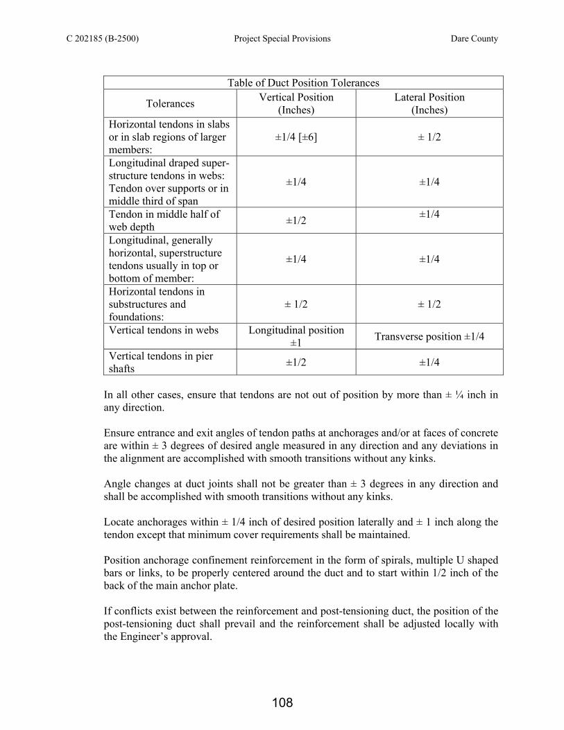
C 202185 (B-2500) Project Special Provisions Dare County
Table of Duct Position Tolerances
Tolerances Vertical Position (Inches)
Lateral Position (Inches)
Horizontal tendons in slabs or in slab regions of larger members:
±1/4 [±6] ± 1/2
Longitudinal draped super- structure tendons in webs: Tendon over supports or in middle third of span
±1/4 ±1/4
Tendon in middle half of web depth ±1/2 ±1/4
Longitudinal, generally horizontal, superstructure tendons usually in top or bottom of member:
±1/4 ±1/4
Horizontal tendons in substructures and foundations:
± 1/2 ± 1/2
Vertical tendons in webs Longitudinal position ±1 Transverse position ±1/4
Vertical tendons in pier shafts ±1/2 ±1/4
In all other cases, ensure that tendons are not out of position by more than ± ¼ inch in any direction. Ensure entrance and exit angles of tendon paths at anchorages and/or at faces of concrete are within ± 3 degrees of desired angle measured in any direction and any deviations in the alignment are accomplished with smooth transitions without any kinks. Angle changes at duct joints shall not be greater than ± 3 degrees in any direction and shall be accomplished with smooth transitions without any kinks. Locate anchorages within ± 1/4 inch of desired position laterally and ± 1 inch along the tendon except that minimum cover requirements shall be maintained. Position anchorage confinement reinforcement in the form of spirals, multiple U shaped bars or links, to be properly centered around the duct and to start within 1/2 inch of the back of the main anchor plate. If conflicts exist between the reinforcement and post-tensioning duct, the position of the post-tensioning duct shall prevail and the reinforcement shall be adjusted locally with the Engineer’s approval.
108
C 202185 (B-2500) Project Special Provisions Dare County
Placing Concrete
(A) Precautions
Use methods to place and consolidate concrete which will not displace or damage any of the post-tensioning ducts, anchorage assemblies, splices and connections, reinforcement or other embedments. Fabricate all duct splices to prevent duct kinks during concrete placement. Use mandrels as needed to maintain duct alignment and shape.
(B) Proving of Post-tensioning Ducts
Upon completion of concrete placement, prove that the post-tensioning ducts are free and clear of any obstructions or damage and are able to accept the intended post-tensioning tendons by passing a torpedo through the ducts. Use a torpedo having the same cross-sectional shape as the duct and that is a 1/4 inch smaller all around than the clear, nominal inside dimensions of the duct. Make no deductions to the torpedo section dimensions for tolerances allowed in the manufacture or fixing of the ducts. For straight ducts, use a torpedo at least 2 feet long. For curved ducts, determine the length so that when both ends touch the outermost wall of the duct, the torpedo is 1/4 inch clear of the innermost wall. If the torpedo will not travel completely through the duct, the Engineer will reject the member, unless a workable repair can be made to clear the duct. The torpedo shall pass through the duct easily, by hand, without resorting to excessive effort or mechanical assistance.
(C) Problems and Remedies
The Engineer will reject ducts or any part of the work found to be deficient. The contractor shall develop a remedial action plan for approval by the Engineer.
Installing Tendons
A high-quality, water-tight seal is expected for all ducts at the bridge site. For all tendons that may have been subject to contamination, in the Engineer's sole discretion, flush the duct before placing the prestressing strands, with lime treated potable water and test for presence of chlorides and oils. It is anticipated that the permitting agencies will require any fluids expelled during flushing at the bridge site will need to be contained. Chlorides in the water shall be less than 600 ppm. When chloride levels are in excess of 600 ppm, continue to flush the duct until the chloride level is below 250 ppm. Blow oil-free compressed air through the duct to remove any excess water in the duct.
Push or pull post-tensioning strands through the ducts to make up a tendon using methods which will not snag on any lips or joints in the ducts. Strands which are pushed should be rounded off the end of the strand or fitted with a smooth protective cap. During the installation of the post-tensioning strand into the duct, the strand shall not be intentionally rotated by any mechanical device.
109

C 202185 (B-2500) Project Special Provisions Dare County
Alternatively, strands may be assembled to form the tendon and pulled through the duct using a special steel wire sock (“Chinese finger”) or other device attached to the end. The ends of the strands may not be electric arc welded together for this purpose. Strands may be brazed together for pulling as long as 1 foot of strand from the brazed end is removed after installation. Round the end of the pre-assembled tendon for smooth passage through the duct. Cut strands using an abrasive saw or equal. Flame cutting is not allowed.
Do not install permanent tendons before the completion of testing as required by these Specifications or Plans. As a sole exception, the tendon to be tested in the “In Place Friction Test” may be installed for the test.
Post-Tensioning Operations
(A) General
Do not apply post-tensioning forces until the concrete has attained the specified compressive strength as determined by cylinder tests. Conduct all stressing operations in the presence of the Engineer.
(B) Stressing Tendons
Tension all post-tensioning steel with hydraulic jacks so that the post-tensioning force is not less than that required by the plans or approved shop drawings, or as otherwise approved by the Engineer. Do not utilize monostrand jacks to stress tendons with five or more strands.
(1) Maximum Stress at Jacking
The maximum temporary stress (jacking stress) in the post-tensioning steel shall not exceed 80% of its specified minimum ultimate tensile strength. Do not overstress tendons to achieve the expected elongation.
(2) Initial and Permanent Stresses
The post-tensioning steel shall be anchored at initial stresses that will result in the long term retention of permanent stresses or forces of no less than those shown on the plans or the approved shop drawings. Unless otherwise approved by the Engineer, the initial stress after anchor set shall not exceed 70% of the specified ultimate tensile strength of the post-tensioning steel.
Permanent stress and permanent force are the stress and force remaining in the post-tensioning steel after all losses, including long term creep and shrinkage of concrete, elastic shortening of concrete, relaxation of steel, losses in the post-tensioning steel from the sequence of stressing, friction and unintentional wobble of the ducts, anchor set, friction in the anchorages and all other losses peculiar to the post-tensioning system.
110
C 202185 (B-2500) Project Special Provisions Dare County
(3) Stressing Sequence
Except as noted on the approved plans or the approved shop drawings developed by the Design Build Team, permanent post-tensioning tendons shall be stressed from both ends. The required force may be applied at one end and subsequently at the other end or simultaneously at both ends. Single end stressing is permitted when the following are satisfied: (a) Space limitations prohibit double end stressing. (b) The calculated elongation of the post-tensioning steel at the second end is 1/2
inch or less and wedges are power seated. (c) Single end stressing applied at alternate ends of paired adjacent post-
tensioning tendons is required to produce a symmetrical force distribution in agreement with the plan design.
For construction in stages where some tendons are required to be stressed before others, install and stress in accordance with the plans or approved shop drawings or as otherwise approved by the Engineer.
(C) Stressing Equipment
Only use equipment furnished by the supplier of the post-tensioning system (tendons, hardware, anchorages, etc.).
(1) Stressing Jacks and Gauges
Each jack shall be equipped with a pressure gauge for determining the jacking pressure. The pressure gauge shall have an accurate reading gauge with a dial at least 6 inches in diameter.
(2) Calibration of Jacks and Gauges
Calibrate each jack and its gauge(s) as a unit. The calibration shall consist of three test cycles with the cylinder extension of the jack in various positions (i.e. 2 inch, 4 inch, 8 inch stroke). At each pressure increment, average the forces from each test cycle to obtain an average force. Perform the calibration with the equipment (jack, pump, hoses, etc.) setup in the same configuration that is intended to be used at the job site. The post-tensioning supplier or an independent laboratory shall perform initial calibration of jacks and gauge(s). Use load cells calibrated within the past 12 months to calibrate stressing equipment. For each jack and gauge unit used on the project, furnish certified calibration charts and curves to the Engineer prior to stressing. Supply documentation denoting the load cell(s) calibration date and tractability to NIST (National Institute of Standards and Technology) along with the jack/gauge calibration.
111

C 202185 (B-2500) Project Special Provisions Dare County
Provide the Engineer with certified calibration charts and curves prior to the start of the work and every six months thereafter, or as requested by the Engineer. Calibrations subsequent to the initial calibration with a load cell may be accomplished by the use of a master gauge. Supply the master gauge to the Engineer in a protective waterproof container capable of protecting the calibration of the master gauge during shipment to a laboratory. Provide a quick-attach hydraulic manifold to enable quick and easy installation of the master gauge to verify the permanent gauge readings. The master gauge shall be calibrated and provided to the Engineer. The master gauge will remain in the possession of the Engineer for the duration of the project.
Any jack repair, such as replacing seals or changing the length of the hydraulic lines, is cause for recalibration using a load cell. No extra compensation will be allowed for the initial or subsequent calibrations or for the use and required calibrations of the master gauge.
(D) Elongations and Agreement with Forces
Ensure that the forces being applied to the tendon and the elongation of the post-tensioning tendon can be measured at all times.
Elongations shall be measured to the nearest 1/16 inch. For the required tendon force, the observed elongation shall agree within 7% of the theoretical elongation or the entire operation shall be checked and the source of error determined and remedied to the satisfaction of the Engineer before proceeding further. Do not overstress the tendon to achieve the theoretical elongation. In the event that agreement between the observed and theoretical elongations at the required force falls outside the acceptable tolerances, the Engineer may, at his discretion and without additional compensation to the Contractor, require additional tests for “Tendon Modulus of Elasticity” and/or “In-Place Friction” in accordance with Sections 4.0(A) and 4.0(B) of this provision.
(E) Friction
The Design Plans shall be prepared based on the assumed friction and wobble coefficients and anchor set noted on the plans. Submit calculations and show a typical tendon force diagram, after friction, wobble and anchor set losses, on the shop drawings based upon the expected actual coefficients and values for the post-tensioning system to be used. Show these coefficients and values on the shop drawings.
If, in the opinion of the Engineer, the actual friction significantly varies from the expected friction, revise post-tensioning operations so the final tendon force is in agreement with the plans.
112

C 202185 (B-2500) Project Special Provisions Dare County
When friction shall be reduced, graphite may be used as a lubricant, subject to the approval of the Engineer.
(F) Wire Failures in Post-tensioning Tendons
Multi-strand post-tensioning tendons, having wires which fail, by breaking or slippage during stressing, may be accepted provided the following conditions are met: (1) The completed structure shall have a final post-tensioning force of at least 98% of
the design total post-tensioning force. (2) For precast or cast-in-place segmental construction and for any similar
construction that has members post-tensioned together across a common joint face, at any stage of erection, the post-tensioning force across a mating joint shall be at least 98% of the post-tensioning required for that mating joint for that stage of erection.
(3) Any single tendon shall have no more than a 7% reduction in cross-sectional area
of post-tensioning steel due to wire failure.
Any of the above conditions may be waived with approval of the Engineer, when conditions permit the Contractor to propose acceptable alternative means of restoring the post-tensioning force lost due to wire failure.
(G) Cutting of Post-tensioning Steel
Cut post-tensioning steel with an abrasive saw or plasma torch within 3/4 to 1 1/2 inches away from the anchoring device. Flame cutting of post-tensioning steel is not allowed.
(H) Record of Stressing Operations
Keep a record of the following post-tensioning operations for each tendon installed: (1) Project name, Project ID; (2) Contractor and/or subcontractor; (3) Tendon location, size and type; (4) Date tendon was first installed in ducts; (5) Reel number for strands and heat number for bars; (6) Tendon cross-sectional area; (7) Modulus of elasticity; (8) Date Stressed; (9) Jack and Gauge numbers per end of tendon; (10) Required jacking force; (11) Gauge pressures; (12) Elongations (theoretical and actual);
113

C 202185 (B-2500) Project Special Provisions Dare County
(13) Anchor sets (anticipated and actual); (14) Stressing sequence (i.e. tendons to be stressed before and after; (15) Stressing mode (one end/ two ends/ simultaneous); (16) Witnesses to stressing operation (Contractor and inspector); (17) Date grouted
Record any other relevant information. Provide the Engineer with a complete copy of all stressing and grouting operations.
(I) Duct Pressure Field Test
After stressing and before grouting internal or external tendons, install all grout caps, inlets and outlets and test the tendon with compressed air to determine if duct connections require repair. In the presence of the Engineer, pressurize the tendon to 50 psi and lock-off the outside air source. Record pressure loss for one minute. A pressure loss of 25 psi is acceptable for tendons having a length of equal to or less than 150 feet and a pressure loss of 15 psi is acceptable for tendons longer than 150 feet. If the pressure loss exceeds the allowable, repair leaking connections using methods approved by the Engineer and retest.
(J) Tendon Protection
Within four hours after stressing, install grout caps and seal all other tendon openings. If acceptance of the tendon is delayed, seal all tendon openings and temporally weatherproof the open ends of the anchorage. If tendon contamination occurs, remove and replace the tendon.
Grouting Operations
(A) Grouting Operations Plan
Submit a grouting operations plan for approval at least six weeks in advance of any scheduled grouting operations. Written approval of the grouting operations plan by the Engineer is required before any grouting of the permanent structure takes place.
At a minimum, the plan will address and provide procedures for the following items: (1) Names and proof of training for the grouting crew and the crew supervisor in
conformance with this specification; (2) Type, quantity, and brand of materials used in grouting including all certifications
required; (3) Type of equipment furnished, including capacity in relation to demand
and working condition, as well as back-up equipment and spare parts; (4) General grouting procedure; Duct pressure test and repair procedures; (5) Method to be used to control the rate of flow within ducts; (6) Theoretical grout volume calculations;
114

C 202185 (B-2500) Project Special Provisions Dare County
(7) Mixing and pumping procedures; (8) Direction of grouting; (9) Sequence of use of the inlets and outlet pipes; (10) Procedures for handling blockages; (11) Procedures for possible post grouting repair.
Before grouting operations begin, a joint meeting of the Design-Build Team, grouting crew and the Engineer will be conducted. At the meeting the grouting operation plan, required testing, corrective procedures and any other relevant issues will be discussed.
(B) Grout Inlets and Outlets
Ensure the connections from the grout pump hose to inlets are free of dirt and are air- tight. Inspect valves to be sure that they can be opened and closed properly.
(C) Supplies
Before grouting operations start, provide an adequate supply of water and compressed air for clearing and testing the ducts, mixing and pumping the grout. Where water is not supplied through the public water supply system, a water storage tank of sufficient capacity shall be provided.
(D) Equipment
(1) General
Provide grouting equipment consisting of measuring devices for water, a high-speed shear colloidal mixer, a storage hopper (holding reservoir) and a pump with all the necessary connecting hoses, valves, and pressure gauge. Provide pumping equipment with sufficient capacity to ensure that the post-tensioning ducts to be grouted can be filled and vented without interruption at the required rate of injection in not more than 30 minutes.
Provide an air compressor and hoses with sufficient output to perform the required functions. Provide vacuum grouting equipment (volumetric measuring type) and experienced operators within 48 hours notice.
(2) Mixer, Storage Hopper
Provide a high speed shear colloidal mixer capable of continuous mechanical mixing producing a homogeneous and stable grout free of lumps and un-dispersed cement. The colloidal grout machinery will have a charging tank for blending and a holding tank. The blending tank shall be equipped with a high shear colloidal mixer. The holding tank shall be kept agitated and at least partially full at all times
115

C 202185 (B-2500) Project Special Provisions Dare County
during the pumping operation to prevent air from being drawn into the post-tensioning duct.
Add water during the initial mixing by use of a flow meter or calibrated water reservoir with a measuring accuracy equal to one percent of the total water volume.
(3) Grout Pumping Equipment
Provide pumping equipment capable of continuous operation which will include a system for circulating the grout when actual grouting is not in progress.
The equipment will be capable of maintaining pressure on completely grouted ducts and will be fitted with a valve that can be closed off without loss of pressure in the duct. Grout pumps will be positive displacement type, will provide a continuous flow of grout, and will be able to maintain a discharge pressure of at least 145 psi. Pumps will be constructed to have seals adequate to prevent oil, air or other foreign substances entering the grout and to prevent loss of grout or water. The capacity will be such that an optimal rate of grouting can be achieved. A pressure gauge having a full scale reading of no more than 300 psi will be placed at the duct inlet. If long hoses (in excess of 100 ft) are used, place two gauges, one at the pump and one at the inlet. The diameter and rated pressure capacity of the grout hoses shall be compatible with the pump output.
(4) Vacuum Grouting Equipment
Provide vacuum grouting equipment consisting of the following: (a) Volumeter for the measurement of void volume. (b) Vacuum pump with a minimum capacity of 10 cfm and equipped with flow-
meter capable of measuring amount of grout being injected. (c) Manual colloidal mixers and/or dissolvers (manual high speed shear mixers),
for voids less than 5.28 gal. in volume. (d) Standard colloidal mixers, for voids 5.28 gal. and greater in volume.
(5) Stand-by Equipment
During grouting operations, provide a stand-by colloidal grout mixer and pump.
116

C 202185 (B-2500) Project Special Provisions Dare County
(E) Grouting
(1) General
Perform test to confirm the accuracy of the volume measuring component of the vacuum grouting equipment each day when in use before performing any grouting operations. Use either water or grout for testing using standard testing devices with volumes of 0.5 gal and 6.5 gal and an accuracy of equal to or less than 4 oz. Perform one test with each device. The results shall verify the accuracy of the void volume measuring component of the vacuum grouting equipment within 1% of the test devise volume and shall verify the accuracy of the grout volume component of the vacuum grouting equipment within 5% of the test devise volume. Ensure the Engineer is present when any tests are performed.
Grout tendons in accordance with the procedures set forth in the approved grouting operation plan. Grout all empty ducts.
(2) Temperature Considerations
Maximum grout temperature shall not exceed 90°F at the grout inlet. Use chilled water and/or pre-cooling of the bagged material to maintain mixed grout temperature below the maximum allowed temperature. Grouting operations are prohibited when the ambient temperature is below 40°F or is 40°F and falling. Postpone grouting operations if freezing temperatures are forecasted within the next two days and it is expected the concrete temperature surrounding the duct will fall below 40oF.
(3) Mixing and Pumping
Mix the grout with a metered amount of water. The materials will be mixed to produce a homogeneous grout.
Continuously agitate the grout until grouting is complete.
(4) Grout Production Test
During grouting operations the fluidity of the grout shall be strictly maintained within the limits established by the grout manufacturer. A target fluidity rate will be established by the manufacturer’s representative, based on ambient weather conditions. Determine grout fluidity by use of either test method found in “Post-tensioning Grout” Project Special Provision. Perform fluidity test for each tendon to be grouted and maintain the correct water to cementitious ratio. Do not use grout which tests outside the allowable flow rates.
Prior to grouting empty ducts condition the grout materials as required to limit the grout temperature at the inlet end of the grout hose to 90°F. Prior to performing
117

C 202185 (B-2500) Project Special Provisions Dare County
repair grouting operations with vacuum grouting, condition the grout materials to limit the grout temperature at the inlet end of the grout hose to 85°F. Check the temperature of the grout at the inlet end of the grout hose hourly.
At the beginning of each day’s grouting operation, obtain a representative sample of grout from the first production batch of grout and perform a wick induced bleed test in accordance with “Post-tensioning Grout” Project Special Provision using this sample. Begin grouting operations after the sample is obtained. If zero bleed is not achieved in the wick induced bleed test at any time during the required test time period, complete the grouting of any partially grouted tendons and do not begin grouting of any new or additional tendons until the grouting operations have been adjusted and further testing shows the grout meets the specified requirements.
(5) Grout Operations
Open all grout outlets before starting the grouting operation. Grout tendons in accordance with the Grouting Operations Plan.
Unless approved otherwise by the Engineer, pump grout at a rate of 16 feet to 50 feet of duct per minute. Conduct normal grouting operations at a pressure range of 10 psi to 50 psi measured at the grout inlet. Do not exceed the maximum pumping pressure of 145 psi at the grout inlet for round ducts and 75 psi for flat ducts in deck slabs.
Use grout pumping methods which will ensure complete filling of the ducts and complete encasement of the steel. Grout shall flow from the first and subsequent outlets until any residual water or entrapped air has been removed prior to closing the outlet.
Pump grout through the duct and continuously discharge it at the anchorage and grout cap outlets until all free water and air are discharged and the consistency of the grout is equivalent to that of the grout being pumped into the inlet. Close the anchorage outlet and discharge a minimum of 2 gallons of grout from the grout cap into a clean receptacle. Close the grout cap outlet.
For each tendon, immediately after uncontaminated uniform discharge begins, perform a fluidity test using the flow cone on the grout discharged from the anchorage outlet. The measured grout efflux time will not be less than the efflux time measured at the pump or minimum acceptable efflux time as established in “Post-tensioning Grout” Project Special Provision. Alternately, check the grout fluidity using the Wet Density method contained in “Post-tensioning Grout” Project Special Provision. The measured density shall fall within the values established in “Post-tensioning Grout” Project Special Provision. The density at the final outlet shall not be less than the grout density at the inlet. If the grout fluidity is not acceptable, discharge additional grout from the anchorage outlet and test the grout fluidity. Continue this cycle until an acceptable grout fluidity is
118

C 202185 (B-2500) Project Special Provisions Dare County
achieved. Discard grout used for testing fluidity. After all outlets have been bled and sealed, elevate the grout pressure to ±75 psi seal the inlet valve and wait two minutes to determine if any leaks exist. If leaks are present, fix the leaks using methods approved by the Engineer. Repeat the above stated process until no leaks are present. If no leaks are present, bleed the pressure to 5 psi and wait a minimum of ten minutes for any entrapped air to flow to the high points. After the minimum ten minutes period has expired, increase the pressure as needed and discharge grout at each high point outlet to eliminate any entrapped air or water. Complete the process by locking a pressure of 30 psi into the tendon. If the actual grouting pressure exceeds the maximum allowed, the inlet will be closed and the grout will be pumped at the next outlet, which has just been, or is ready to be closed as long as a one-way flow is maintained. Grout will not be pumped into a succeeding outlet from which grout has not yet flowed. If this procedure is used, the outlet/inlet, which is to be used for pumping will be fitted with a positive shut-off and pressure gage. When complete grouting of the tendon cannot be achieved by the steps stated herein, stop the grouting operation. After waiting 48 hours, fill the tendon with grout in accordance with the procedure outlined in Section 10.0(E)(8) of this provision.
(6) Vertical Grouting
Grouting of cable stays is not covered by this specification. For all vertical tendons, provide a standpipe at the upper end of the tendon to store bleed water and grout, maintain the grout level above the level of the prestressing plate and anchorage. This device will be designed and sized to maintain the level of the grout at an elevation which will assure that bleeding will at no time cause the level of the grout to drop below the highest point of the upper anchorage device. Design the standpipe to allow all bleed water to rise into the standpipe, not into the uppermost part of the tendon and anchorage device.
Discharge grout and check grout fluidity as described in Section 10.0(E)(5) of this provision. As grouting is completed, the standpipe will be filled with grout to a level which assures that, as settlement of the grout occurs, the level of the grout will not drop below the highest point in the upper anchorage device. If the level of the grout drops below the highest point in the anchorage device, immediately add grout to the standpipe. After the grout has hardened, the standpipe will be removed. In the presence of the Engineer, visually inspect for voids using an endoscope or probe. Fill all voids found in the duct using volumetric measuring vacuum grouting processes.
For vertical tendons in excess of 100 feet or if the grouting pressure exceeds the maximum recommended pumping pressure, then grout will be pumped at increasingly higher outlets which have been or are ready to be closed as long as a
119

C 202185 (B-2500) Project Special Provisions Dare County
one-way flow of grout is maintained. Grout will be allowed to flow from each outlet until all air and water have been purged prior to using that outlet for pumping.
(7) Construction Traffic and Operations Causing Vibrations
During grouting and for a period of 4 hours upon completion of grouting, eliminate vibrations from all sources such as moving vehicles, jackhammers, compressors, generators, pile driving operations, soil compaction, etc., that are operating within 300 feet down-station and 300 feet up-station of the ends of the span in which grouting is taking place.
(8) Post-grouting Operations and Inspection
Do not remove or open inlets and outlets until the grout has cured for 24 to 48 hours. Remove all outlets located at anchorages and high points along the tendon to facilitate inspection and perform inspections within one hour after the removal of the inlet/outlet. Drill and inspect all high points along the tendon as well as the inlets or outlets located at the anchorages. Depending on the geometry of the grout inlets, drilling may be required to penetrate to the inner surface of the trumpet or duct. Use drilling equipment that will automatically shut-off when steel is encountered. Unless grout caps are determined to have voids by sounding, do not drill into the cap. Perform inspections in the presence of the Engineer using endoscopes or probes. Within four hours of completion of the inspections, fill all duct and anchorage voids using the volumetric measuring vacuum grouting process.
Seal and repair all anchorage and inlet/outlet voids that are produced by drilling for inspection purposes as specified in Section 11.0(B) of this provision. Remove the inlet/outlet to a minimum depth of 2 inches. Use an injection tube to extend to the bottom of the drilled holes for backfilling with epoxy. Post grouting inspection of tendons may utilize the following statistical frequency for inspection: (a) For the first 20 tendons, inspect all outlets located at anchors and tendon high
points by drilling and probing with an endoscope or probe. If one or more of the inspection locations are found to contain a defect (void), continue testing all tendons until 20 consecutive tendons have been inspected and no voids have been found.
(b) When no defects are detected as defined in No. 1 above, the frequency of inspection can be reduced to inspect every other tendon (50%). If a defect is located, inspect the last five tendons grouted. Return to Step 1 above and renew the cycle of 100% tendon inspections.
120

C 202185 (B-2500) Project Special Provisions Dare County
If tendon grouting operations were prematurely terminated prior to completely filling the tendon, drill into the duct and explore the voided areas with an endoscope. Probing is not allowed. Determine the location and extent of all voided areas. Install grout inlets as needed and fill the voids using volumetric measuring vacuum grouting equipment.
(9) Grouting Report
Provide a grouting report signed by the Design-Build Team and/or the Subcontractor within 72 hours of each grouting operation for review by the Engineer.
Report the theoretical quantity of grout anticipated as compared to the actual quantity of grout used to fill the duct. Notify the Engineer immediately of shortages or overages. Information to be noted in the records shall include but not necessarily be limited to the following: identification of the tendon; date grouted; number of days from tendon installation to grouting; type of grout; injection end and applied grouting pressure, ratio of actual to theoretical grout quantity; summary of any problems encountered and corrective action taken.
Forming and Repairs of Holes and Block-Outs
(A) Repair of Lifting and Access Holes
(1) Repair all holes with Magnesium Ammonium Phosphate Concrete (MAPC) meeting the physical properties requirements below. Immediately before casting the concrete (within 24 hrs.), mechanically clean and roughen the mating concrete surfaces to remove any laitance and expose the small aggregate. Grit blasting or water blasting using a minimum 10,000 psi nozzle pressure is required. Flush surface with water and blow dry. Form, mix, place and cure the material in strict compliance with the manufacturer’s recommendations.
The MAPC material shall meet or exceed the following physical properties.
Requirement Test Method Test Value
Minimum Compressive Strength (at 28 days), psi ASTM C109 8,500
Minimum Flexural Strength (at 28 days), psi ASTM C348 600
Minimum Slant Shear Bond (at 14 days), psi ASTM C882 2,500
Time of Setting (Initial), minutes ASTM C191 15 to 60
Maximum Scaling Resistance ASTM C672 No scaling
121

C 202185 (B-2500) Project Special Provisions Dare County
Maximum Length Change (at 28 days), % Allowable expansion in water cured compared to length at one day
0.03
Allowable shrinkage in air cured compared to length at one day
ASTM C157 -0.03
Maximum Expansion due to Sulfate Resistance (after 52 week of immersion), %
ASTM C1012 0.1
Maximum Chloride Absorption at 21 days, % NCHRP 12-19A* 1.5
* Use cube specimens meeting the requirements of ASTM C109.
(2) Upon completion of the deck grooving, coat the repaired holes, block-outs and an
area extending 6 inches outside the perimeter of the repair with a High Molecular Weight Methacrylate (HMWM). The methacrylate system shall be a three component system consisting of: a. Methacrylate monomer b. Cumene hydroperoxide (CHP) initiator c. Cobalt promoter.
Use initiator and promoter approved by the monomer manufacturer.
Use a methacrylate material that meets the following physical and performance requirements: Physical Properties of Methacrylate Resin Viscosity (Brookfield RVT) 14-20 cps at 50 rpm Density (ASTM D1481) 8.5 – 9.0 lb/gal at 77o F Flash Point (ASTM D93) >200 o F (Pensky Martens CC) Order Low Bulk Cure Speed 3 Hours @ 73oF (max) Surface Cure 8 Hours @ 73oF (max) Gel Time (ASTM D2471) 60 minutes (max) Tack Free Time 5 Hours (max) (at 72oF and 50% RH) Compressive Strength (AASHTO T106) 6,500 psi (min) Tensile Strength (ASTM C307) 1,300 psi (min) Shear Bond Adhesion (ASTM C882) 600 psi (min) Wax Content 0%
The monomer shall have a shelf life of no less than 12 months and shall be no more than 8 months old at the time of application. Provide each container shipped to the job site with the following information on a manufacturer’s label: manufacturer’s name, product name, lot or batch number, date of production, and drum serial
122

C 202185 (B-2500) Project Special Provisions Dare County
number. Identify the catalysts by their generic classification and provide the date of manufacture.
(3) Use uniformly graded 6-20 (or similar), clean, bagged, blast sand for spreading over the applied polymer on bridge decks and other riding surfaces. Certify that the sand has a maximum moisture content that does not exceed 0.25% and that the maximum amount of dust or other material that may pass through a No. 200 sieve (-200 content) is not greater than 0.75%. Store the sand at a location that will preserve the above described conditions and characteristics of the sand until applied.
(4) On the day of application, thoroughly power sweep the area to be treated to remove all dust, dirt or debris present. On bridge decks and other riding surfaces, use a tractor mounted (or similar) power broom with non-metallic bristles suitable for the intended purpose. Use a power vacuum after sweeping when sealing cracks on grooved bridge decks. Re-clean the deck as necessary just prior to the application as debris may be blown back onto the work area by adjacent traffic or other means. If present, remove oils and oil based substances from the concrete surface using an approved solvent.
(5) Provide adequate containment to prevent the sealer material from flowing beyond the designated area of application. Plug any drain holes or openings within the work area. Prevent airborne material from dispersing
(B) Repair of Grout Inlets and Outlets
Place threaded plastic caps in all inlet/outlet locations required in the plans. Repair inlets/outlets as shown on the plans using an epoxy grout, Type 5 epoxy meeting the requirements of Article 1081 Standard Specifications. Prepare the surface to receive the epoxy material in strict compliance with the manufacturer’s recommendations.
Protection of Post-Tensioning Anchorages
(A) Epoxy Grout (1) Within seven days upon completion of the grouting, protect the anchorage of post-
tensioning bars and tendons as indicated in the plans. The application of the elastomeric coating may be delayed up to 90 days after grouting. Use plastic or stainless steel threaded caps to plug all grout inlets/outlets. Use an epoxy grout to construct all pourbacks located at anchorages meeting the following requirements.
(2) These epoxy materials are to be used to protect the anchorages of post-tensioning
tendons or bars and other uses indicated in the plans. The material shall produce a low exothermic reaction and have flow and fill characteristics suitable for machine
123

C 202185 (B-2500) Project Special Provisions Dare County
base plate applications. The material will be extended with the aggregate supplied by the manufacturer. Mix with the full aggregate loading unless the use of less aggregate is approved by the Engineer.
(3) The material shall be factory pre-proportioned including factory supplied aggregate.
Deliver products in original containers with manufacturer’s name, date of manufacture, product identification label and batch numbers. Materials shall be within the manufacturer’s recommended shelf life. Store and condition the product in full compliance with manufacturer’s recommendations.
Property Test Value Test Method Compressive Strength, Cubes (7 day cure at 77ºF) > 10,000 psi ASTM C579B
Tensile Strength at 7 days > 2,100 psi ASTM C307
Flexural Strength (7 day cure at 77ºF) > 3,600 psi ASTM C580
Modulus of Elasticity (7 day cure at 77ºF) < 2,100,000 psi ASTM C580
Coefficient of Thermal Expansion at 74 to 210ºF
< 20 x 10-6 in/in/ºF
ASTM C531
Peak Exotherm, Specimen, 12 x 12 x 3 in. < 150ºF ASTM D2471
Slant Shear at 7 days (Bond Strength to Concrete) > 3000 psi ASTM C882
Thermal Compatibility 5 Cycles Passed ASTM C884 Linear Shrinkage at 7 days 0.025% ASTM C531 Flowability and Bearing Area 90% Contact area ASTM C1339 Gel Time, Specimen 12 x 12 x 3 in. < 4:00 (hr.) ASTM D2471
(4) The epoxy grout plus aggregate mix shall meet or exceed the specified physical
properties stated herein as determined by the following standard ASTM test methods.
(5) Remove all laitance, grease, curing compounds, surface treatments, coatings and oils by grit blasting or water blasting using a minimum 10,000 psi nozzle pressure. Flush surface with water and blow dry. Surfaces shall be clean, sound and without any standing water. In case of dispute, use ACI 503 for substrate testing and develop a minimum of 175 psi. tension (pull-off value).
(6) Mix and apply epoxy as per manufacturer’s current standard technical guidelines.
Construct all pourbacks in leak proof forms creating neat lines. The epoxy grout may require pumping for proper installation. Construct forms to maintain a liquid head to insure intimate contact with the concrete surface. Use vents as needed to provide for the escape of air to insure complete filling of the forms.
124

C 202185 (B-2500) Project Special Provisions Dare County
(B) Elastomeric Coating (1) After the epoxy pourback has cured per the manufacturer’s recommendations, coat
the exposed surfaces of pourbacks plus at least 12 inches of concrete surrounding the pourback with a 30 to 45 mils thick elastomeric coating system meeting the following requirements. Epoxy pourbacks to receive an elastomeric coating include, but are not limited to, those pourbacks beneath expansion joints and those pourbacks at anchorages within the interior of the box girder. Pourbacks located on the visible exterior surface of the bridge superstructure shall not receive an elastomeric coating.
(2) The elastomeric coating system shall provide a waterproof barrier over the
designated post-tensioning anchorages and or other areas designated in the plans. The components of the coating system shall be supplied by a single manufacturer and sold as a waterproof coating system. The surface preparation and application of the coating system shall be applied in strict accordance with the manufacturer’s specifications.
(3) The use of an epoxy prime coat is dependent upon the requirements of the
manufacturer’s waterproofing system. The polyurethane chemistry may be either waterborne aromatic (moisture-curing) or aromatic (moisture-sensitive). The minimum thickness of the system shall not be less than 30 mils. The cured coating system shall meet the following requirements:
Property Test Value Test Method
Hardness, Shore A Between 60 and 90 ASTM D2240 Tensile Strength ≥750 psi ASTM D412 Elongation ≥400% ASTM D412 Tear Strength >70 pli ASTM C957 Abrasion Resistance H-18 wheels 1,000 gm/wheel ≤350 mg loss / 1,000 revs. ASTM C957
Crack Bridging 1,000 Cycles System Passes ASTM C957
Elongation Recovery ≥94% ASTM C957
(4) Supply the elastomeric coating system with an aliphatic polyurethane top coating for use on epoxy pourbacks in the bridge substructure.
(5) Field Qualification Testing: Attain a numerical rating of not less than 9 in accordance with ASTM D610 and ASTM D1654 and 9F in accordance with ASTM D714; the coating should not blister, soften or loosen bond at the end of the test period; there will be no corrosion in the field per ASTM D610; color retention, ΔE≤3, in accordance with ASTM D2244; and 10% max gloss loss in accordance with ASTM D523 when applied to test location and exposed at the Department’s beach corrosion test site or applied at a test location. The coatings will be evaluated initially following an exposure period of 18 months. The coatings shall continue to provide
125

C 202185 (B-2500) Project Special Provisions Dare County
acceptable protection and performance for a period of 5 years. Application characteristics shall be judged acceptable prior to beach testing.
(6) Assure concrete or other substrates are structurally sound, clean and dry. Concrete shall be a minimum of 28 days old. Remove all laitance, grease, curing compounds, surface treatments, coatings and oils by grit blasting or water blasting using a minimum 10,000 psi nozzle pressure to establish the anchor pattern. Blow the surface with compressed air to remove the dust or water. Construct a 2 x 4 ft concrete test block with a similar surface texture to the surfaces to be coated and coat a vertical face with the elastomeric coating system chosen. Determine the number of coats required to achieve a coating thickness between 30 to 45 mils without runs and drips. Mix and apply elastomeric coating as per manufacturer’s current standard technical specifications. Spray or roller application is permitted (spray application preferred). Have the coating manufacturer representative on site to supervise and comment on the application of the elastomeric coating onto the test block. Apply coatings using approved and experienced personnel with a minimum of three years experience applying similar polyurethane systems. Submit the credentials of these persons to the Engineer for review and consideration for approval.
Post-tension details (vertical profile, anchorage and grouting, and an anchorage protection) shall be in accordance with the document entitled “Post Tensioning Standard Details” dated January 20, 2011, which by reference is incorporate and made a part of this contract. POST-TENSIONING GROUT Description
This provision covers grouts to be used to protect post-tensioning steel. Grout applications are differentiated into three applications: horizontal, vertical and repair. Grouts shall be prepackaged in moisture proof containers. Grout bags shall indicate application, date of manufacture, LOT number and mixing instructions. Any change of materials or material sources requires new testing and certification of the conformance of the grout with this specification. A copy of the Quality Control Data Sheet for each lot number and shipment sent to the job site shall be provided to the Contractor by the grout supplier and furnished to the Engineer. Materials with a total time from manufacture to usage in excess of six months shall be tested and certified by the supplier that the product meets the QC Control Specifications before use or the material shall be removed and replaced.
Materials
Refer to Division 10 of the Standard Specifications
Item Article
Water "Water for Concrete" Special Provision
Prepackaged Grout (meet the requirements of this provision)
126

C 202185 (B-2500) Project Special Provisions Dare County
Requirements
(A) Grout Physical Properties (1) Gas Generation
The grout shall not contain aluminum or other components which produce hydrogen, carbon dioxide or oxygen gas.
(2) Laboratory Test
The grout shall meet or exceed the specified physical properties stated herein as determined by the following standard and modified ASTM test methods conducted at normal laboratory temperature (65-78°F) and conditions. Conduct all grout tests with grout mixed to produce the minimum time of efflux. Establish the water content to produce the minimum and maximum time of efflux.
Property Test Value Test Method
Total Chloride Ions Max. 0.08% by weight of cementitious material
ASTM C1152
Fine Aggregate (if utilized) 99% passing the No. 50 Sieve (300 micron)
ASTM C136*
Hardened Height Change @ 24 hours and 28 days
0.0% to +0.2% ASTM C1090**
Expansion <2.0% for up to 3 hours ASTM C940
Wet Density – Laboratory Report maximum and minimum obtained test value 1b/cu ft
ASTM C185
Wet Density – Field Report maximum and minimum obtained test value 1b/cu ft
ASTM C138
Compressive Strength 28 day (Average of 3 cubes) >7,000 psi ASTM C842
Initial Set of Grout Min. 3 hours Max. 12 hours ASTM C953
Time of Efflux*** Min. 20 sec Max. 30 sec ASTM C939
(a) Immediately after mixing or Min. 9 sec Max. 20 sec
ASTM C939****
Max. 30 sec ASTM C939 (b) 30 minutes after mixing with remixing for 30 sec or
Max. 30 sec ASTM C939****
127

C 202185 (B-2500) Project Special Provisions Dare County
Bleeding @ 3 hours Max. 0.0 percent ASTM C940*****
Permeability @ 28 days Max. 2,500 coulombs at 30 V for 6 hours ASTM C1202
*Use ASTM C117 procedure modified to use a #50 sieve. Determine the percent passing the #50 sieve after washing the sieve. **Modify ASTM C1090 to include verification at both 24 hours and 28 days. ***Adjustments to flow rates will be achieved by strict compliance with the manufacturer’s
recommendations. The time of efflux is the time to fill a one liter container placed directly under the flow cone.
****Modify the ASTM C939 test by filling the cone to the top instead of to the standard level. *****Modify ASTM C940 to conform with the wick induced bleed test as follows:
(a) Use a wick made of a 20 inch length of ASTM A416 seven wire 0.5 inch diameter strand. Wrap the strand with 2 inch wide duct or electrical tape at each end prior to cutting to avoid splaying of the wires when it is cut. Degrease (with acetone or hexane solvent) and wire brush to remove any surface rust on the strand before temperature conditioning.
(b) Condition the dry ingredients, mixing water, prestressing strand and test apparatus overnight at 65 to 75°F.
(c) Mix the conditioned dry ingredients with the conditioned mixing water and place 800 ml of the resulting grout into the 1,000 ml graduate cylinder. Measure and record the level of the top of the grout.
(d) Completely insert the strand into the graduated cylinder. Center and fasten the strand so it remains essentially parallel to the vertical axis of the cylinder. Measure and record the level of the top of the grout.
(e) Store the mixed grout at the temperature range listed above in (b).
(f) Measure the level of the bleed water every 15 minutes for the first hour and hourly for two successive readings thereafter.
(g) Calculate the bleed water, if any, at the end of the three hour test period and the resulting expansion per the procedures outlined in ASTM C940, with the quantity of bleed water expressed as a percent of the initial grout volume. Note if the bleed water remains above or below the top of the original grout height. Note if any bleed water is absorbed into the specimen during the test.
128

C 202185 (B-2500) Project Special Provisions Dare County
Accelerated Corrosion Test Method (ACTM)
Perform the ACTM as outlined in Appendix B of the “Specification for Grouting of Post-Tensioning Structures” published by the Post-Tensioning Institute. Report the time to corrosion for both the grout being tested and the control sample using a 0.45 water-cement ratio neat grout. A grout that shows a longer average time to corrosion in the ACTM than the control sample and the time to corrosion exceed 1,000 hours is considered satisfactory.
Variation in Testing for Specific Applications
(1) Horizontal Applications Horizontal grout applications are defined as grouting of all superstructure tendons
and transverse substructure tendons in caps, struts, etc. All physical requirements defined in Section 3(A) and 3(B) of this provision are applicable for grouts used in horizontal applications.
(2) Vertical Applications
Vertical grout applications are defined as grouting of substructure column tendons. All physical requirements defined in Sections 3(A) and 3(B) of this provision are applicable for grouts used in vertical applications. In addition, perform the Schupack Pressure Bleed Test Procedure for Cement Grouts for Post-Tensioned Structures as outlined in Appendix C of the “Specification for Grouting of Post-Tensioned Structures” published by the Post-Tensioning Institute. Report the percent bleed for the grout tested. Test grout at the specified pressure of 100 psi. An acceptable test will result in no bleed water (0.0 percent).
(3) Repair Applications
Repair applications are used to augment grouting operations which did not completely fill the duct or anchorage. For new construction, repairs may be made with the same grout approved for use in the tendon as long as the volume of the void is less 0.5 gal. In all other cases, use a non-sanded grout meeting the requirements of Section 3(A) and 3(B) of this provision with a modified maximum permeability of 2,800 coulombs (ASTM C1202 at 30 volts). Non-sanded grouts shall have 95% passing on the #100 sieve and 90% passing the #170 sieve as determined by ASTM C33. Each sieve may be washed and dried before weighing in accordance with the procedure in ASTM C117 modified for sieve size.
Grout Mixing
The material shall be mixed in accordance with the manufacturer’s recommendations.
129

C 202185 (B-2500) Project Special Provisions Dare County
QUALITY MANAGEMENT
This provision presents minimum documentation and implementation requirements for a comprehensive Quality Management Plan. The Quality Management Plan shall be submitted to the Department within the timelines established in this provision for the Department’s and FHWA approval. The Technical Proposal shall include a synopsis of the Design-Build Team’s anticipated Quality Management Plan.
The Design-Build Team shall establish and implement a Quality Management Plan. The purpose of the Quality Management Plan is to: ensure that the Design-Build Team provides the Department a completed project that meets Contract requirements and minimize the occurrence of design and construction non-conformances through active and effective monitoring of processes. The Design-Build Team shall manage the project and their work such that the Department has the ability to substantiate that the requirements of the Contract are being met and substantiate that appropriate payments for the progress are made.
The Design-Build Team shall develop, maintain and implement a comprehensive Quality Management Plan that reflects the Contract requirements and the Design-Build Team’s processes and procedures for effectively performing the quality management for the Project. The contents of the Quality Management Plan approved by the Department and FHWA are hereby incorporated as part of the contract. In the event that a conflict arises between the approved Quality Management Plan and the synopsis thereof as required as part of the Technical Proposal, the approved Quality Management Plan shall govern.
Quality Control is defined by actions taken by the Design-Build Team, his consultants, subcontractors and suppliers to ensure that the work meets the project requirements as referenced in the Request for Proposals and referenced documents and all applicable standards of good practice.
Quality Assurance is the application of planned and systematic reviews by the Department or its agents which demonstrate that quality control practices are being effectively implemented.
The Design-Build Team shall designate three separate individuals as their Project Quality Manager, Construction Quality Manager, and Design Quality Manager. The Project Quality Manager shall be an individual who serves a non-production role on the team and is the single most accountable person on the Design-Build Team for ensuring quality control in all areas of the project, including both design and construction. The Construction Quality Manager and Design Quality Manager may serve production roles but are responsible for the construction quality and design quality, respectively. The Quality Management Plan shall reflect the overall quality approach, philosophy, and a discussion of methods that will be used to assure that the contracting and subcontracting relationships will support the Department’s and the Design-Build Team’s quality objectives. The Quality Management Plan shall be organized in accordance with, and shall include the topics set out in the following outline:
130

C 202185 (B-2500) Project Special Provisions Dare County
Project Quality Management, including but not limited to:
• Quality Policy Statement
• Organizational Requirements with contact information of Quality Team
• Roles and Responsibilities of the Quality Team
• Administrative processes and procedures common to both design and construction quality management
• Quality Records management processes and procedures
• Design Quality Control, shall include but not be limited to:
• Processes and procedures for Design development including checking, peer review, cross-discipline coordination for developing Project Plans, Project Specifications and Estimates with supporting technical documentation
• Plan/Processes and procedures for managing Design Reviews and changes during design and construction
• Plan/Process for Independent Design Checks
• Plan/Protocols for Design Decision Making
• Plan/Protocols for Design Communication, Coordination, and Collaboration
• Plan/Protocols for Managing Department Reviews and Responses to submittals and alterations to the contract
• Design and engineering support during construction, witnesses tests, reviewing quality inspection and test records, responding to RFIs and field changes
• Plan/Protocols for Independent Auditing of the Design Quality Management Program.
• Construction Quality Control, shall include but not be limited to:
• Plan/Processes for Construction management and administration
• Plan/ Construction Decision Making
• Plan/Protocols for performance and documentation of Inspection, Testing and maintaining quality certifications, materials receipts, data/information storage, HiCAMS data entry, etc.
• Plan/Protocols for Payment Request and Tracking
• Plan/Protocols for Managing Reviews and Responses to Construction Documentation (RFIs, RFCs, Field Changes, Design Changes during Construction)
• Plan/Protocols for Managing and Tracking approved construction changes
• Plan/Protocols for Managing and Controlling Construction Schedule
• Plan/Protocols for Construction Communication, Coordination, and Collaboration
• Plan/Protocols for Independent Auditing of the Construction Quality Management Program as well as quality oversight processes and procedures.
131

C 202185 (B-2500) Project Special Provisions Dare County
• Project Quality Management Forms and Checklists shall be used to facilitate and document QC efforts. The details of many of these forms and checklists require the design to be advanced. One of the key checklists to be included in the Design-Build Team’s Quality Management Plan is the pre-work activity checklist that depicts all items required to perform the particular construction effort that can be used at a pre-construction meeting by the Design-Build Team to review with all participants, including the Department, the construction means and methods, subcontractor involvement, materials and inspection / testing requirements, HiCAMS data entry requirements, project certification requirements, QC/QA personnel approval. This meeting typically will include a review of safety and security protocols as well as environmental controls.
• The Department has the right to perform quality inspections and audits of the Design-Build Team’s management, design, construction, environmental compliance, and maintenance activities; the Design-Build Team’s Quality Management activities; the quality of materials and fabricated products; and the quality of workmanship of the completed project.
Within 30 days following the execution of the contract the Design-Build Team shall submit a Quality Management Plan that describes the QC activities provided and managed for the design and permitting activities. The Department will provide comments within 21 calendar days of the submittal. The Design-Build Team shall submit the Quality Management Plan for acceptance within 21 days of receipt of the Department’s comments. At least 90 days prior to the expected construction date, the Design-Build Team shall submit for Department review, a Quality Management Plan that describes how QC will be provided and managed for all construction activities. The Department will provide comments within 30 calendar days of the submittal. The Design-Build Team shall submit the Quality Management Plan for acceptance within 30 days of receipt of the Department’s comments. Revisions and updates to the Quality Management Plan may be proposed by the Design-Build Team as the Work progresses. Changes to the Quality Management Plan shall be provided to the Department no later than 30 days prior to the work to which the revision applies. The Department will have 15 calendar days to review and comment. These revisions and updates may occur in one or more iterations. The Design-Build Team shall not initiate any work that is impacted by such a program change unless and until the Department has reviewed and accepted the change.
Design Quality Management shall be the Design-Build Team’s sole responsibility to provide Project Plans, Working Plans, and Project Specifications of such a nature to deliver the finished construction work in accordance with all Contract requirements. Department review and comments pertaining to design documents shall not relieve the Design-Build Team of that responsibility.
The Design-Build Team shall not begin construction work until all Department comments related to that work are resolved to the satisfaction of the Department. The Design-Build Team shall perform each of the following:
132

C 202185 (B-2500) Project Special Provisions Dare County
• Manage the design and design quality of the work;
• Coordinate with and obtain necessary approvals from authorities regarding temporary road diversions and detours, shutdowns, temporary traffic diversions, utility relocations, and all other matters for which authorization may be required;
• Document how permit requirements are met in accordance with the Environmental Compliance Plan;
• Ensure that the responsible Design Professionals complete the necessary reviews, evaluations and quality checks in accordance with the procedures set out in the Quality Management Plan and file appropriate documentation and certifications; and
• Ensure that the Project Quality Manager certifies that quality procedures have been followed in accordance with all Contract documents and the Quality Management Plan.
• The same procedures used for checking the design of permanent components of the project also apply to design of major temporary components and construction sequences of the work that affect the permanent components.
The Design Quality Manager shall be responsible for the supervision and quality of all design work and design processes, including but not limited to each of the following:
• Accuracy;
• Adequacy;
• Conformance to professional standards of practice;
• Compliance with all legal requirements and contractually-mandated Standards and other Contract requirements;
• Quality; and
• Fitness for purpose and function as specified or implied in the Request for Proposals and referenced documents.
The design portion of the Quality Management Plan shall be submitted for Department review and comment prior to the start of design. This document shall include both the quality responsibilities of the Design Manager and the independent responsibilities of the Design Quality Manager and shall be specific to each stage of design development. The Design-Build Team shall make a single comprehensive design check and Design Review for developed plans and specifications for each of the five (5) stages of design development:
• Interim Designs;
• Final Design;
• Working Plans; and
• Specifications.
The Design-Build Team shall carry out independent design checks by senior engineers not involved in the production of the design being reviewed that have equal or greater qualifications and experience as the Responsible Engineer for the design being checked. The Design-Build
133

C 202185 (B-2500) Project Special Provisions Dare County
Team shall provide to the Department a plan / process and written procedures for this Independent Design Check and shall include, as a minimum, the following structural components:
• Any specialized erection equipment used for the placement of segmental sections of the bridge structures; and
• Bridge structure foundation, column and superstructure one unit of each structure type
Independent design checks are comprised of design assessment and analytical checks as follows:
• Design Assessment – is a review of general compliance with the requirements of the Contract, taking into consideration the following areas:
• Project design criteria;
• Applicable codes and standards;
• Methods of analysis;
• Computer software and its validation;
• Interface requirements;
• Maintenance requirements;
• Materials and material properties;
• Durability requirements;
• Constructability;
• Context Sensitivity; and
• Environmental Compliance.
• Analytical Check – using separate calculations (and without reference to Designer’s calculations) to establish the structural adequacy and integrity of critical structural members. This includes, but not limited to the following:
• Structural geometry and modeling;
• Material properties;
• Member properties;
• Loading intensities;
• Foundation loads; and
• Structural boundary conditions.
All design exceptions from specified Standards and/or Industry practices shall be provided by the Design-Build Team, stating why exceptions are being proposed with supporting documentation; and shall be submitted prior to the applicable design submittal.
It is expected that frequent Design Review meetings internal to the Design-Build Team be conducted by the Design Manager. The Design Quality Manager, the Design Manager,
134

C 202185 (B-2500) Project Special Provisions Dare County
Responsible Engineer, and any Design Professionals having significant input into the design or review shall be present. The Design-Build Team shall notify and invite the Department to participate in all design reviews. At a minimum, the Design Manager shall organize and facilitate monthly design review workshops with the Department to discuss upcoming design submittals. The Department may also invite stakeholders to attend. The Department’s participation, or lack thereof, in design reviews shall not relieve the Design-Build Team of its responsibility for the satisfactory completion of the work in accordance with all Contract requirements.
The Design-Build Team shall provide or make available to review meeting participants all design documents (e.g., drawings, reports, specifications, Basis of Design Memorandums and other technical memorandums as necessary to support design decisions) pertinent to the design review, including all prior comments and actions resulting therefrom. The Design-Build Team shall prepare and distribute minutes from the review meetings. Design Review meetings shall also be conducted as requested by the Department.
The Design-Build Team shall be responsible for demonstrating that any proposed specifications meet or exceed the minimum Contract and permit requirements, as determined by Department in its sole discretion, and are suitable and appropriate to control the Work.
Working Plans reviews, prior to submittal to the Department, are the responsibility of the Design-Build Team to assure conformance with the Final Design plans and specifications and in accordance with the Contract requirements. The Design-Build Team shall verify pertinent dimensions in the field prior to conducting a Working Plan review. The Design-Build Team shall check, review, and certify Working Plans prior to their use in fabrication and/or construction. Approved working plans shall be maintained in the Design-Build Team’s file and available if requested by the Department. Discrepancies or changes shown in the Working Plans require the responsible Engineer, the Design Manager, and the Design Quality Manager’s reviews, approvals, and certifications. The Project Quality Manager shall notify the Department in writing of any authorized changes to the Working Plans from the Final Design.
Design Quality Records shall be maintained by the Design-Build Team in an auditable format according to the Quality Management Plan procedures. The Department has the right to audit the quality records for compliance with the Quality Management Plan and the Contract requirements. Upon completion of the Project, the Quality Records shall be submitted to the Department.
The Design-Build Team shall develop and implement a Quality Program for all phases of construction. The Design-Build Team, through the Quality Management Plan, shall be responsible for the quality of construction, including the workmanship and products of subcontractors, fabricators, suppliers, and vendors both onsite and off-site. Responsibility for the quality of construction includes environmental compliance monitoring per the Environmental Compliance Plan that is included in the Quality Management Plan.
135
C 202185 (B-2500) Project Special Provisions Dare County
The Construction Quality Manager shall oversee, manage, certify and perform Quality Management activities as defined in the Quality Management Plan and the Contract requirements.
• Construction Quality Control (QC) – All construction processes, procedures, and workmanship shall be inspected by the Design-Build Team’s QC representatives. This shall include the observations, measurements, and documentation specified in the Design-Build Team’s Quality Management Plan, the Request for Proposals and referenced documents. Inspection, observations, verification of conformance to specified requirements, measurements, results, non-conformances, and required corrective actions shall be documented on Design-Build Team’s forms as defined in the QC plan.
• Construction QC Testing – The Design-Build Team’s QC representatives shall perform sampling and testing of field-tested materials in accordance with the Quality Management Plan and the Contract requirements. The Design-Build Teams QC representatives shall be certified to the Department’s requirements at a level appropriate for the items being sampled/tested, and shall provide the Department the names, telephone numbers, and copies of certifications for all personnel performing field testing. Testing requirements shall be defined in the Quality Management Plan supported by a recognized national organization (AASHTO, ASTM, etc.), and shall mean the latest version of that test method or Contract Specification for the Work in effect on the day the testing is performed, unless otherwise directed by the Department in writing. The Quality Management Plan shall address failing tests, retests and unsuitable test results.
• Certified Testing Laboratory – QC laboratory testing of field-tested materials shall be conducted by testing laboratories that are approved and qualified by the Department or AASHTO certified for the applicable tests to be conducted.
• Field-Tested Materials – The Design-Build Team is responsible for providing QC sampling and testing, furnishing materials of the quality specified, and furnishing quality level analysis during production when required by the Quality Management Plan, the Contract specifications, and as required by the Standard Specifications and Minimum Sampling Guide. The Design-Build Team’s construction QC testers shall perform sampling and testing for process control and QC consistent with the Quality Management Plan, Contract specifications, and the Standard Specifications. Any deviations from the sampling and testing methods and frequencies indicated in the Quality Management Plan or the Contract specifications shall require the Materials and Tests Unit’s concurrence prior to the start of the Work.
• Non-Field Tested Materials and products – The Design-Build Team shall provide materials meeting all Contract requirements, along with all material’s conformance and quality compliance documents as required by the Minimum Sampling Guide and the Standard Specifications. Quality compliance documents shall be as required in Section 106 of the Standard Specifications. Non-field tested materials shall be accepted for use according to the Contract specifications, the Minimum Sampling Guide, the Standard Specifications and the Quality Management Plan. Manufactured products that are normally pre-inspected by the Department’s Materials and Tests Unit will continue to be the responsibility of the Department.
136

C 202185 (B-2500) Project Special Provisions Dare County
• Materials and equipment installed as part of any permanent construction or as required by the Departments policy or FHWA guidelines shall be new, unless otherwise specified. The Contract shall use first-class materials and equipment throughout the performance of the Contract, and it is agreed that any material for which no particular specification is given shall be of the highest quality of its class or kind. For the purpose of this subsection, "new" shall mean purchased specifically for the Project for which award was made.
• Department testing laboratories shall perform independent assurance (IA) or verification tests of field-tested materials in coordination with the QC testing laboratories performing QC tests of materials on behalf of the Design-Build Team. QA laboratories shall be either Department laboratories or Department-contracted independent testing laboratories.
• The Design-Build Team shall have documentation that materials and equipment conform to all Contract requirements available at the Project Site no less than 24-hours prior to installation or use of such materials or equipment. This documentation shall be retained at the Project Site office.
The Design-Build Team, at minimum, shall identify the Project Quality Manager, Design Quality Manager, and the Construction Quality Manager as part of the key personnel in the Technical Proposal. The Design-Build Team's executive management will review the quality system at defined intervals sufficient to ensure its continuing suitability and effectiveness in satisfying the requirements of this standard and the Design-Build Team's stated quality policy and objectives. Executive management reviews will be held at least at three-month intervals. Records of such reviews will be maintained. Minutes will be taken of the review meetings and these minutes will be maintained as quality records. Copies of minutes will be provided to the Department on request. The Design-Build Team shall assign a Responsible Engineer(s) for each Design-Build Team-designated Design Unit (construction Milestone). Submittals to the Department for each discipline shall be accompanied by certification from the Design Manager, Design Quality Manager and Project Quality Manager that the design and design checks comply with all contract requirements and that all quality process and procedures have been followed in accordance with the approved Quality Management Plan. The Responsible Engineer(s) will sign and seal design reports, Project Plans, and Project Specifications for the assigned Design Unit(s). The Responsible Engineer will review Working Plans for conformance with final design. Each Responsible Engineer must be a North Carolina licensed Professional Engineer.
137

C 202185 (B-2500) General Dare County GENERAL The State will not be bound by oral explanations or instructions given at any time during the bidding process or after award. Only information that is received in response to this RFP will be evaluated; reference to information previously submitted will not suffice as a response to this solicitation. NO CONTACT CLAUSE To ensure that information is distributed equitably to all short-listed Design-Build Teams, all questions and requests for information shall be directed to the State Contract Officer through the Design-Build e-mail address. This precludes any Design-Build Team Member, or representative, from contacting representatives of the Department, other State Agencies or Federal Agencies either by phone, e-mail or in person concerning the Design-Build Project. USE OF TERMS Throughout this RFP and all manuals, documents and standards referred to in the RFP the terms Contractor, Bidder, Design-Builder, Design-Build Team, Team, Firm, Company, and Proposer are synonymous. Throughout this RFP and all manuals, documents and standards referred to in the RFP, the terms NCDOT, Department, Engineer, and State are synonymous. Throughout this RFP and all documents referred to in the RFP, references to the Technical Proposal include all Technical Proposal supplemental information that may be submitted in response to a Best and Final Offer RFP. DESIGN REFERENCES Design references developed and published by NCDOT and those developed and published by other agencies and adopted for use by NCDOT which are to be used in the design of this project may be obtained by contacting Contract Standards and Development within the Technical Services Division. Standard prices for materials, which the Department normally sells for a fee, will be in effect. The Design-Build Team shall be responsible for designing in accordance with the applicable documents and current revisions and supplements thereto. REVIEW OF SUBMITTALS Major design milestones and required design submittals shall be identified as activities on a CPM, bar chart, or other scheduling tool. This schedule shall be submitted to the Transportation Program Management Director and Resident Engineer concurrently with the first design submittal, or within 30 days of the contract award, whichever is earlier. The schedule shall be revised and resubmitted as design milestones change or as directed by the Transportation Program Management Director. Submittals will be reviewed within 10 working days (15 working days for temporary structures, overhead sign assemblies, FEMA compliance documents, and temporary shoring and 20 working days for post-tensioning or segmental design submittals) from the date of receipt by NCDOT unless otherwise stipulated in the scope of work. All
138

C 202185 (B-2500) General Dare County submittals shall be prepared and submitted in accordance with the “Design-Build Submittal Guidelines”, which by reference are incorporated and made a part of this contract. All submittals shall be made simultaneously to the Transportation Program Management Director and the Resident Engineer. The Department will not accept subsequent submittals until prior submittal reviews have been completed for that item. The Design-Build Team shall inform the Transportation Program Management Director in writing of any proposed changes to the NCDOT preliminary designs, Technical Proposal and / or previously reviewed submittals and obtain approval prior to incorporation. The Design-Build Team shall prioritize submittals in the event that multiple submittals are made based on the current schedule. All submittals shall include pertinent Special Provisions. No work shall be performed prior to Department review of the design submittals. OVERVIEW The NCDOT TIP Project B-2500, constitutes the replacement of the Herbert C. Bonner Bridge across Oregon Inlet from Bodie Island to Hatteras Island and improvements to NC 12 from north of Oregon Inlet to Rodanthe in Dare County. The Parallel Bridge Corridor with NC12 Transportation Management Plan Alternative has been chosen as the Selected Alternative. This alternative proposes to replace the Bonner Bridge with a parallel bridge and maintaining existing NC 12 through the Pea Island National Wildlife Refuge. The NCDOT Design-Build Project B-2500 constitutes Phase I of this alternative, namely the replacement of the Bonner Bridge, with a bridge approximately 3 miles in length and a typical section consisting of two 12-foot travel lanes and two 8-foot shoulders. The Phase I work of the Parallel Bridge Corridor with NC12 Transportation Management Plan Alternative is substantively identical to the Phase I work identified in the previous preferred alternative Phased Approach/Rodanthe Bridge. Project services shall include, but are not limited to: • Design Services – completion of construction plans, including Record Drawings • Construction Services – necessary to build and ensure workmanship of the designed facility • Permit Preparation / Application - development of all documents for required permits
The FEIS / Final Section 4(f) Evaluation was signed on September 17, 2008 The EA was approved on May 7, 2010 The ROD was signed on December 20, 2010
Construction Engineering Inspection will be provided by the NCDOT Division personnel and/or an external private engineering firm. GENERAL SCOPE The scope of work for this project includes design, construction and management of the project. The design work includes all aspects to construct a bridge approximately 3 miles in length and a typical section consisting of two 12-foot travel lanes and two 8-foot shoulders and the demolition of the existing structure. The designs shall meet all appropriate latest versions of AASHTO Policy on Geometric Design of Highways and Streets, AASHTO LRFD Bridge Design Specifications (including the errata issued in June 2010), Manual of Uniform Traffic Control
139

C 202185 (B-2500) General Dare County Devices, other manuals referenced herein, and all NCDOT design policies that are current as of the Technical and Price Proposal submission date or the Best and Final Offer submission date. Construction shall include, but not be limited to, all necessary clearing, grading, roadway, drainage, structures, utility coordination and relocation, and erosion and sediment control work items for the proposed two-lane facility. Construction engineering and management shall be the responsibility of the Design-Build Team. Construction shall comply with 2006 NCDOT Standard Specifications for Roads and Structures and any special provisions. Areas of work required for this project shall include, but are not limited to the following items:
Roadway Design Structure Design Hydraulic Design Permit Application Subgrade Stabilization Foundation Design for Structures and Roadway Geotechnical Investigation and Load Testing Erosion and Sediment Control Design and Implementation R/W Utilities, Conflicts and / or Construction Traffic Control and Pavement Marking Design Sign Design ITS Design Construction Project Management Design and Construction Management Construction Surveying Location and Surveys Lighting (Construction Only) Public Information
All designs shall be in Microstation format using Geopak software (current version used by the Department). DESIGN AND CONSTRUCTION PERFORMED BY DESIGN-BUILD TEAM The design work consists of the preparation of all construction documents for constructing a bridge approximately 3 miles in length and a typical section consisting of two 12-foot travel lanes and two 8-foot shoulders as outlined in the Scope of Work section of this RFP. The Design-Build Team shall prepare final designs, construction drawings and special provisions. The Design-Build Team shall acknowledge that project documents furnished by the Department are preliminary and provided solely to assist the Design-Build Team in the development of the project design. The Design-Build Team shall be fully and totally responsible for the accuracy and completeness of all work performed under this contract and shall save the State harmless and shall be fully liable for any additional costs and all claims against the State which may arise due to errors, omissions and negligence of the Design-Build Team in performing the work required by this contract.
140

C 202185 (B-2500) General Dare County There shall be no assignment, subletting or transfer of the interest of the Design-Build Team in any of the work covered by the Contract without the written consent of the State, except that the Design-Build Team may, with prior written notification of such action to the State, sublet property searches and related services without further approval of the State. The Design-Build Team shall certify all plans, specifications, estimates and engineering data furnished by the Team. All work by the Design-Build Team shall be performed in a manner satisfactory to the State and in accordance with the established customs, practices, and procedures of the North Carolina Department of Transportation, and in conformity with the standards adopted by the American Association of State Highway Transportation Officials, and approved by the U.S. Secretary of Transportation as provided in Title 23, U.S. Code, Section 109 (b). The decision of the Engineer / State / Department shall control in all questions regarding location, type of design, dimension of design, and similar questions. Alternate designs, details, or construction practices (such as those employed by other states, but not standard practice in NC) are subject to Department review and will be evaluated on a case by case basis. The Design-Build Team shall not change team members, subconsultants or subcontractors identified in the Statement of Qualifications (SOQ) or Technical Proposal without written consent of the Engineer or the State Contract Officer. In addition, subconsultants and subcontractors not identified in the SOQ or Technical Proposal shall not perform any work without written consent by the Engineer. Individual offices of the Design-Build Team not identified in the Statement of Qualifications or the Technical Proposal submitted shall not perform any work without written consent by the Engineer. Failure to comply with this requirement may be justification for removing the Team from further consideration for this project and disqualification from submitting on future Design-Build Projects. All firms shall be prequalified by the Department for the work they are to perform. Joint Ventures, LLCs or any legal structures that are different than the existing prequalification status must be prequalified prior to the Technical and Price Proposal submittal deadline. Subcontractors need only be prequalified prior to performing the work. Design firms should be prequalified prior to the Technical and Price Proposal submittal deadline. If not prequalified at the time of the Technical and Price Proposal submittal deadline, the prime contractor shall be solely responsible for either (1) ensuring that the design firm is prequalified prior to its first design submittal or (2) replacing that firm with a prequalified firm. Design firms and Natural Systems firms are prequalified by the particular office performing the work. If the work is to be performed by an office other than the one that is prequalified, that office shall be prequalified prior to any design submittals. ETHICS POLICY Employees employed by the Design-Build Team or employees employed by any subconsultant for the Design-Build Team to provide services for this project shall comply with the Department’s ethics policy. Failure to comply with the ethics policy will result in the employee's
141

C 202185 (B-2500) General Dare County removal from the project and may result in removal of the Company from the Department’s appropriate prequalified list. APPROVAL OF PERSONNEL The Department will have the right to approve or reject any personnel, assigned to a project by the Design-Build Team. The Design-Build Team or any subcontractor for the Design-Build Team which are employed to provide services for this project shall not discuss employment opportunities or engage the services of any person or persons, now in the employment of the State during the time of this contract, without written consent of the State. In the event of engagement, the Design-Build Team or their subcontractors shall restrict such person or persons from working on any of the Design-Build Team's contracted projects in which the person or persons were “formerly involved” while employed by the State. The restriction period shall be for the duration of the contracted project with which the person was involved. Former Involvement shall be defined as active participation in any of the following activities:
Drafting the contract Defining the scope of the contract Design-Build Team selection Negotiation of the contract cost (including calculating manhours or fees); and Contract administration
An exception to these terms may be granted when recommended by the Secretary and approved by the Board of Transportation. Failure to comply with the terms stated above in this section shall be grounds for termination of this contract and / or not being considered for selection of work on future contracts for a period of one year. SUBMITTAL OF TECHNICAL AND PRICE PROPOSALS Technical and / or Price Proposals that do not adhere to all the requirements noted below may be considered non-responsive and may result in the Department not considering the Design-Build Team for award of the contract or reading their Price Proposal publicly. Technical and Price Proposals will be accepted until 4:00 p.m. Local Time on Friday, July 1, 2011, at the office of the State Contract Officer:
Mr. Randy A. Garris, PE Contract Standards and Development
1020 Birch Ridge Drive Century Center Complex - Building B
Raleigh, NC 27610
No Proposals will be accepted after the time specified.
142

C 202185 (B-2500) General Dare County Proposals shall be submitted in 2 separate, sealed parcels containing the Technical Proposal in one and the Price Proposal in the other parcel.
TECHNICAL PROPOSAL
Technical Proposals shall be submitted in a sealed package. The outer wrapping shall clearly indicate the following information:
Technical Proposal Submitted By: (Design-Build Team's Name)
Contract Number C202185 TIP Number B-2500
Dare County NC 12 – Replacement of Herbert C. Bonner Bridge across Oregon Inlet from Bodie Island to
Hatteras Island
Technical Proposal Requirements
14 Copies 8 ½ inch by 11 inch pages except that one 11 X 17 inch fold out page is permitted for the purpose of presenting an organizational chart. No other fold out pages will be permitted.
Printed on one side only Double-spaced
Font size 12 Minimal font size 10 is permissible within embedded tables, charts, or graphics. No more
than 60 pages, excluding the introductory letter to Mr. Randy Garris, P.E. (two-page maximum length) and the 11 inch by 17 inch appropriate plan sheets
Key Project Team members, identified in the Statement of Qualifications, shall not be modified in the Technical Proposal without written approval of the Department. Any such request should be sent to the attention of Mr. Randy Garris, PE, at the address below:
NCDOT- Contract Standards and Development Century Center Complex - Building B
1020 Birch Ridge Drive Raleigh, NC 27610
PRICE PROPOSAL
Price Proposals shall be submitted in a sealed package. The outer wrapping will clearly indicate the following information:
Price Proposal Submitted by (Design-Build Team’s Name)
Contract Number C202185 TIP Number B-2500
Dare County NC 12 – Replacement of Herbert C. Bonner Bridge across Oregon Inlet from Bodie Island to
Hatteras Island
143

C 202185 (B-2500) General Dare County The Price Proposal shall be submitted by returning the Request for Proposals with the item sheets completed, and all required signatures and bonds. Failure to execute the required documents may render the proposal non-responsive.
EVALUATIONS
Decisions based on cost alone will not establish the design standards for the project. Technical Proposals shall address the technical elements of the design and construction of the project. The Technical Review Committee will consider the understanding of the project, the anticipated problems and the solutions to those problems, in addition to other evaluation criteria identified herein. The Design-Build Team’s Technical Proposal shall be developed using narratives, tables, charts, plots, drawings and sketches as appropriate. The purpose of the Technical Proposal is to document the firm's understanding of the project, demonstrate the Team’s capabilities to complete the project, document their selection of appropriate design criteria, and state their approach and schedule for completing all design and construction activities. The review of design plans by the Department is not intended to reflect a reviewer’s personal preferences, but rather to ensure that all contract requirements are met, sound engineering judgment is exercised by the Design-Build Team, and that the Design-Build Team adheres to all referenced documents, including but not limited to, design standards, codes, memos and manuals. As such, the award of the Design-Build contract does not in any way imply that the NCDOT accepts the details of the Technical Proposal submitted by the Design-Build Team. TECHNICAL PROPOSAL EVALUATION CRITERIA The Technical Proposal will be evaluated in each of the following major categories: 1. Design-Build Team Management – 11 points
Design Management
• Describe the Design-Build Team’s concept of design management. The Technical Proposal shall identify key positions and subordinate organizational units. Any Small Private Services Firms proposed shall also be noted.
• Describe the plan for the coordination of civil / structural, utilities, traffic maintenance, constructability and environmental responsibility.
• Provide a narrative description of the proposed location of the design office(s) and their respective responsibilities.
• Describe how the designs developed by different firms and offices will be integrated. • Describe how design personnel will interface with the construction personnel. • Describe the overall strengths of the Design Team and their ability to fulfill the
design requirements of this project.
144
C 202185 (B-2500) General Dare County
Construction Management
• Describe the Design-Build Team’s concept of the project construction management organization and how it interrelates with the other elements of the Design-Build Team’s organization for the project.
• Describe the Design-Build Team’s approach to partnering and enhanced coordination with Department and CEI firm personnel during construction.
• Provide a brief narrative description of the Design-Build Team’s proposed plan for performing construction on the project. This description shall include at least the following:
• A construction organization chart for the project, showing the relationships between functions shown on the chart and the functional relationships with subcontractors.
• The chart shall indicate how the Design-Build Team intends to divide the project into work segments to enable optimum construction performance.
• Descriptions of those categories of work that the Design-Build Team anticipates will be performed by the Design-Build Team’s own direct labor force and those categories that will be performed by subcontractors.
• The Design-Build Team’s plans and procedures to insure timely deliveries of materials to achieve the project schedule.
• Describe the overall strengths of the construction team and their ability to fulfill the construction and construction management requirements of this project.
• Describe the Design-Build Team’s approach to site access and material staging.
• Outline your plan to address diversity through the utilization of DBE subcontractors and firms. Detail how this plan will be implemented and monitored throughout the life of the project. Discuss the extent to which the DBE goal will be satisfied or exceeded for this project.
2. Quality Management – 20 points
• Describe how the Design-Build Team will comply with the quality control requirements for both design and construction. Specifically, include a narrative synopsis of the procedures and commitments to quality as will be made in the Design-Build Team’s Quality Management Plan as outlined in the Project Special Provision entitled Quality Management Plan. It is anticipated that roughly 8 – 10 pages of the Technical Proposal shall be devoted to this discussion.
• The Design-Build Team should detail the number of inspectors they expect the Department to furnish, during various phases, to allow satisfactory progress of project construction.
• The narrative shall include both design and construction activities.
3. Responsiveness to RFP – 30 points
Natural Environmental Responsibility
• Describe the Design-Build Team’s approach to addressing environmental concerns within the project boundaries.
145

C 202185 (B-2500) General Dare County
• Identify efforts to minimize impacts on wetlands, submerged aquatic vegetation, and other environmentally sensitive areas.
• Identify innovative approaches to minimize any impacts in environmentally sensitive areas. Describe any temporary impacts and associated minimization approaches.
• Describe the Design-Build Team’s understanding of the overall approach to permitting and the Team’s comfort level with obtaining the required permits within the allowed timeframe.
• Describe the anticipated duration of temporary impacts resulting from barge access, haul roads, work bridges, and other means of construction access.
• Identify barge access and dredging needs, and the measures intended to minimize disturbance from dredging and barge positioning and movement.
• Identify areas of jetting that is intended and the methods that will be used to minimize disturbance and turbidity that results from jetting and/or jetting spoils.
• Describe any Notice of Violations (NOVs) the Design-Build team members have received within the last five years from regulatory agencies in North Carolina or any other State and the disposition of each listed NOV.
• Describe the Design-Build Team’s approach to addressing areas of critical habitat as outlined in the project commitments of the Record of Decision.
• Describe in general terms the methods proposed for bridge demolition.
Design Features
• Show plan view of design concepts with key elements noted. • Identify preliminary horizontal and vertical alignments of all roadway and bridge
elements. • Show typical section(s) for the mainline of the project and the bridge. • Identify drainage designs to be implemented. • Identify the bridge type to be constructed, including any special design features or
construction techniques needed. If post-tensioned elements or segmental box construction are used, include details such as transverse tensioning, number of anticipated tendons/strands, and other pertinent details.
• Identify construction sequencing and special supporting design details. • Identify how the tie-in at the southern terminus of the bridge will occur and how the
proposed alignment will fall within the limited easement. • Describe the use of any retaining walls or reinforced slopes steeper than 3:1 including
their limits and types. • Identify how permanent access will be provided to the fishing pier on Hatteras Island. • Identify design features that will allow access to the structure and the design features
that will allow the structure to be extended to the south in future phases, with no or minimal disruption to traffic.
• Describe foundation types to be used and how they may vary along the bridge length. • Identify all bridge appurtenances including signing and ITS devices. • Describe any geotechnical investigations to be performed by the Design-Build Team,
including load test programs.
146

C 202185 (B-2500) General Dare County
• Discuss the sensitivity of the proposed foundation type(s) to final design 100 yr. scour elevations, including the relative impacts that deeper scour elevations may have on their foundation type, pile or drilled pier length, cost and schedule.
• Identify any special aesthetics considerations that will be part of the design. • Describe how any utility conflicts will be addressed and any special utility design
considerations. Describe how the Design-Build Team’s design and construction methods minimize the Department’s utility or septic field relocation costs.
4. Long Term Maintenance – 8 points
• Describe any special materials, not referenced elsewhere in the contract, incorporated into the project that would result in long term reduction in maintenance.
• Describe any special designs or construction methods that would reduce future maintenance costs to the Department.
• For any atypical construction methods such as post-tensioning and grouting, identify what measures will be taken to maximize bridge service life.
• Identify all corrosion mitigation measures that will be used whether required by the RFP or offered beyond the requirements of the RFP and the effects that these measures may have on the bridge service life.
• Describe any additional voluntary non-acceptance testing the Design-Build Team will perform to ensure an enhanced bridge service life.
• Identify any conservative design criteria that will be used for the foundation design that will enhance bridge service life.
• Estimate the long term (minimum twenty year) cost savings resulting from incorporation of these special materials, design, or construction methods into the project.
5. Schedule and Milestones – 15 points
• Provide a detailed schedule for the project including design, permitting, and construction activities. The schedule shall show the sequence and continuity of operations.
• The schedule shall also include the Design-Build Team’s final completion date and substantial completion date. These dates shall be clearly indicated on the Project Schedule and labeled “Final Completion Date” and “Substantial Completion Date”.
• The substantial completion date will constitute 10 of the 15 points allocated to this evaluation category. The other 5 points will be attributed to the final completion date, proper sequencing in the schedule, and credibility of the schedule.
6. Right of Way Minimization – 5 points
• Provide the amount of easement, including metes and bounds and acreage, required within the Pea Island National Wildlife Refuge along the southern terminus of the project. A minimum of 3 points will be assigned in this category if a proposer can tie the proposed alignment into the existing 100 ft. easement. No points will be assigned in this category for a proposer that requires the entire 3.2 acres of easement
147

C 202185 (B-2500) General Dare County
previously identified by the Department at the southern terminus. This solution should be largely consistent with the concept shown on the Corridor Hearing Map such that acceptance by the US Fish and Wildlife is likely.
• The Design-Build Team may include in their Technical Proposal one additional concept for further minimizing easement requirements from the Pea Island National Wildlife Refuge. This option may be one that is not consistent with the concept shown on the Corridor Hearing Map such that special approval from US Fish and Wildlife is necessary post-award. If this option is provided, the calculations of new easement and returned easement acreage shall be provided in the Technical Proposal, but the metes and bounds information is not required in the Technical Proposal for this option. A maximum of one additional extra credit point beyond the 5 points attributable to this category may be assigned based on the additional reduction of needed easement and/or increased returned easement, and the Department's determination of the likelihood that the optional concept will ultimately be accepted by the US Fish and Wildlife.
• Provide the metes and bounds and acreage of existing easement that can be returned to the Pea Island National Wildlife Refuge after providing for access to the existing parking lot and fishing pier.
• To expedite easement acquisition, provide the amount of easement, including metes and bounds and acreage, required within the Cape Hatteras National Seashore along the northern terminus of the project. In regards to the easement needs within the Cape Hatteras National Seashore, only that portion of new easement north of Station 3635+00 –LREV- will be used in the evaluation of the Technical Proposals. Therefore, provide the total acreage of new easement required north of Station 3635+00 –LREV- in the Technical Proposal. In addition, for the purpose expediting easement acquisition only, provide the amount of easement, including metes and bounds and acreage, required within the entire boundary of the Cape Hatteras National Seashore. Provide a description of the impacts, if any, to the Oregon Inlet Fishing Center septic system and RV dump station.
• Provide a description of any additional temporary construction easement or Special Use Permit necessary to construct the project as well as a description of the need.
7. Innovation – 4 points
• Identify any aspects of the design or construction elements that the Design-Build
Team considers innovative. Include a description of alternatives that were considered whether implemented or not.
8. Maintenance of Traffic and Safety Plan – 4 points
Maintenance of Traffic • Describe any traffic control requirements that will be used for each construction
phase. • Describe how recreational and commercial boating traffic will be accommodated
throughout construction. Describe how the final design will affect, the current boating traffic patterns to and from the Oregon Inlet Fishing Center.
148

C 202185 (B-2500) General Dare County
• Describe how traffic will be maintained as appropriate and describe the Design-Build Team’s understanding of any time restrictions noted in the RFP.
• Specifically describe how access to the Oregon Inlet Fishing Center, Coast Guard Station and fishing catwalks on the southern end of the existing bridge will be maintained.
• Address how hauling will be conducted. • If temporary shoring will be required, provide the type and why it is required. • Describe clearly how traffic will be maintained at the southern terminus of the
proposed bridge when conducting the tie-in within the existing easement on Hatteras Island.
• Describe your public involvement activities offered, including methods to provide the public with information and access to project personnel.
Safety Plan • Describe the safety considerations specific to the project. • Discuss the Design-Build Team's overall approach to safety. • Describe any proposed improvements that will be made prior to or during
construction that will enhance the safety of the work force and/or travelling public both during and after the construction of the project.
9. Oral Interview – 3 points
• The Design-Build Team’s Project Management Team shall present a brief introduction of the project team and design / construction approach.
• The presentation shall be held to no more than 45 minutes. • The Department will use this interview to ask specific questions about the Team’s
Technical Proposal, background, philosophies, and approach to the project. • Presentation, questions, and answers shall not exceed 120 minutes. No more than 12
people from the Design-Build Team may attend. The Department will use the information presented in the oral interview to assist in the evaluation of the Technical Proposal.
Additional Warranty and / or Guarantee • The Extra Credit for this project attributable to warranties/guarantees shall be a
Maximum of 4 Points. A twelve-month guarantee as outlined in the Twelve-Month Guarantee Project Special Provision is required for this project. However, the Design-Build Team may provide additional warranties and / or guarantees at their discretion. The Design-Build Team may be awarded additional points as “extra credit” to be added to the Technical Score. The Design-Build Team may provide warranties and/or guarantees for major components of the project. Examples of major components are pavements, bridge components, and sign structures. If additional warranties and/or guarantees are offered, the Design-Build Team shall indicate in the Technical Proposal the general terms of the warranties and/or guarantees, a list of the items
149

C 202185 (B-2500) General Dare County covered, performance parameters, notification and response parameters for corrective action, and evaluation periods. The Department will be responsible for annual inspections of the components covered by all warranties and/or guarantees offered by the Design-Build Team that extend beyond the required Twelve-Month Guarantee. The warranties and/or guarantees shall also define how disputes will be handled. Prior to the first partial payment, the Design-Build Team shall submit a document that provides additional warranty/guarantee specifics in sufficient detail that allows the document to be made a part of the contract through supplemental agreement. The Technical Proposal shall also outline whether the warranty/guarantee will be supported by a performance bond, corporate guarantee, escrow account, irrevocable letter of credit or other such instrument. No direct payment will be made for warranties and / or guarantees. Payment will be considered incidental to the lump sum price for the contract.
SELECTION PROCEDURE There will be a Technical Review Committee (TRC) composed of five or more senior personnel from involved engineering groups that will evaluate the Technical Proposal on the basis of the criteria provided in the Request for Proposals. The Department reserves the right to engage a private engineering firm to assist in the evaluation of Technical Proposals and post-award submittals, especially in regards to specialized bridge designs and construction methods. The selection of a Design-Build Team will involve both technical quality and price. The Technical Proposals will be presented to the TRC for evaluation. The TRC shall first determine whether the proposals are responsive to the requirements of the Request for Proposals. The Department reserves the right to ask for clarification on any item in the Technical Proposal. A written response to this request for clarification shall be provided to the Department prior to the opening of the Price Proposals. The contents of the written response may affect the Technical Review Committee’s determination of the Technical Proposal’s responsiveness and/or the overall evaluation of the Technical Proposal. If any commitments or clarifications provided in the written response conflict with the contents of the Technical Proposal, the contents of the written response will govern and be incorporated into the contract. Each responsive Technical Proposal shall be evaluated based on the rating criteria provided in the Request for Proposals. The TRC will submit an overall consensus Technical Proposal score for each Design-Build Team to the State Contract Officer.
Quality Credit Evaluation Factors for Technical Proposals
Design-Build Team Management 11 Quality Management 20 Responsiveness to Request for Proposal 30 Long Term Maintenance 8 Schedule and Milestones 15 Right of Way Minimization 5 Innovation 4 Maintenance of Traffic and Safety Plan 4 Oral Interview 3 Maximum Score 100
150
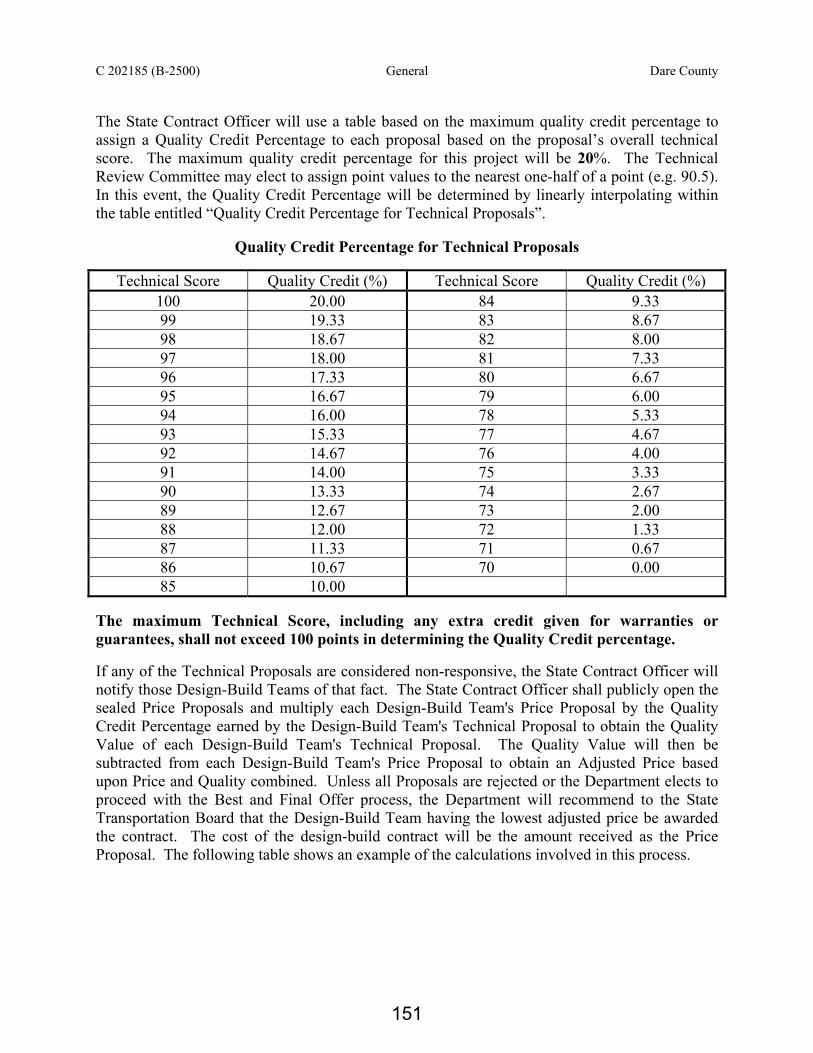
C 202185 (B-2500) General Dare County The State Contract Officer will use a table based on the maximum quality credit percentage to assign a Quality Credit Percentage to each proposal based on the proposal’s overall technical score. The maximum quality credit percentage for this project will be 20%. The Technical Review Committee may elect to assign point values to the nearest one-half of a point (e.g. 90.5). In this event, the Quality Credit Percentage will be determined by linearly interpolating within the table entitled “Quality Credit Percentage for Technical Proposals”.
Quality Credit Percentage for Technical Proposals
Technical Score Quality Credit (%) Technical Score Quality Credit (%) 100 20.00 84 9.33 99 19.33 83 8.67 98 18.67 82 8.00 97 18.00 81 7.33 96 17.33 80 6.67 95 16.67 79 6.00 94 16.00 78 5.33 93 15.33 77 4.67 92 14.67 76 4.00 91 14.00 75 3.33 90 13.33 74 2.67 89 12.67 73 2.00 88 12.00 72 1.33 87 11.33 71 0.67 86 10.67 70 0.00 85 10.00
The maximum Technical Score, including any extra credit given for warranties or guarantees, shall not exceed 100 points in determining the Quality Credit percentage. If any of the Technical Proposals are considered non-responsive, the State Contract Officer will notify those Design-Build Teams of that fact. The State Contract Officer shall publicly open the sealed Price Proposals and multiply each Design-Build Team's Price Proposal by the Quality Credit Percentage earned by the Design-Build Team's Technical Proposal to obtain the Quality Value of each Design-Build Team's Technical Proposal. The Quality Value will then be subtracted from each Design-Build Team's Price Proposal to obtain an Adjusted Price based upon Price and Quality combined. Unless all Proposals are rejected or the Department elects to proceed with the Best and Final Offer process, the Department will recommend to the State Transportation Board that the Design-Build Team having the lowest adjusted price be awarded the contract. The cost of the design-build contract will be the amount received as the Price Proposal. The following table shows an example of the calculations involved in this process.
151

C 202185 (B-2500) General Dare County
An Example of Calculating Quality Adjusted Price Ranking
Proposal Technical Score
Quality Credit (%)
Price Proposal ($)
Quality Value ($)
Adjusted Price ($)
A 95 16.67 3,000,000 500,100 2,499,900 B 90 13.33 2,900,000 386,570 2,513,430
C * 90 13.33 2,800,000 373,240 2,426,760 D 80 6.67 2,700,000 180,090 2,519,910 E 70 0.00 2,600,000 0 2,600,000
* Successful Design-Build Team – Contract Cost $2,800,000 Opening of Price Proposals Prior to opening the Price Proposals, the State Contract Officer will provide to each Design-Build Team their Technical Score in a sealed envelope. The sealed envelope will contain that Team’s score only. At the time and date specified, the State Contract Officer will open the Price Proposals and calculate the percentage difference between the Price Proposals submitted and the Engineer’s Estimate. Should all of the Price Proposals be within an acceptable range or below the Engineer’s Estimate the State Contract Officer will proceed to calculate the quality credit and publicly read the Price Proposal, Technical Score, and Adjusted Price as outlined in the selection procedure above. Should any one or more of the Price Proposals be within an acceptable range or below the Engineer’s Estimate and the remaining Price Proposals exceed an acceptable range of the Engineer’s Estimate the State Contract Officer will go to a separate location to calculate the quality credit and determine if the Design-Build Team with the lowest Adjusted Price is within an acceptable range of the Engineer’s Estimate. Should the Price Proposal of the Design-Build Team with the lowest Adjusted Price be within an acceptable range of the Engineer’s Estimate or below the Engineer’s Estimate the State Contract Officer will proceed to publicly read the Price Proposals, Technical Scores, and Adjusted Prices. Should the Price Proposal of the Design-Build Team with the lowest Adjusted Price exceed an acceptable range of the Engineer’s Estimate the State Contract Officer will publicly read the Price Proposals only and the Department will then determine whether to proceed to request a Best and Final Offer (BAFO) as outlined below. Should all Price Proposals submitted exceed an acceptable range of the Engineer’s Estimate the State Contract Officer will publicly read the Price Proposals only. The Department will then determine whether to proceed to request a Best and Final Offer (BAFO) as outlined below. In the event that the Department elects to not proceed with a Best and Final Offer (BAFO), then the State Contract Officer will schedule a date and time to publicly reiterate all Price Proposals, and read all Technical Scores and Adjusted Prices.
152

C 202185 (B-2500) General Dare County
e Provided the Department elects to proceed to request a Best and Final Offer (BAFO), at the date and time specified, the State Contract Officer will open the Best and Final Offer Price Proposals and proceed to publicly read all Price Proposals, Technical Scores and Adjusted Prices. Best and Final Offer In the event initial Price Proposals exceed an acceptable range of the Engineer’s Estimate or if the Department feels it is necessary for any reason the Department may choose to make amendments to the details of the RFP and request a Best and Final Offer from all of the previously short-listed teams. Alternately, the Department may choose to redistribute to the short-listed Design-Build Teams another RFP for the project with no amendments to the RFP scope. After receipt of the redistributed RFP, the Design-Build Team has the option of changing their Technical Proposal details. If the Design-Build Team changes any component of the Technical Proposal, the TRC will review those amended components of the Technical Proposal and reevaluate the scores accordingly. The Design-Build Team shall highlight the changes to bring them to the Department’s attention. A revised total score will be calculated, if appropriate, based on these amendments to the Technical Proposal. Additional oral interviews will not be held. The Design-Build Teams shall submit both a revised Price Proposal and a revised Technical Proposal (if applicable) at the time, place, and date specified in the redistributed RFP. A revised Quality Credit Percentage (if required) and Adjusted Price will be determined. This will constitute the Design-Build Team’s Best and Final Offer. Award of the project may be made to the Design-Build Team with the lowest Adjusted Price on this Best and Final Offer for the project. Stipend A stipulated fee of $150,000 will be awarded to each short-listed Design-Build Team that provides a responsive, but unsuccessful, Design-Build Proposal. If a contract award is not made, all short-listed Design-Build Teams that provide a responsive Design-Build Proposal shall receive the stipulated fee. Once award is made, or a decision is made not to award, unsuccessful Design-Build Teams will be notified of the opportunity to apply for the stipulated fee. If the Design-Build Team accepts the stipulated fee, the Department reserves the right to use any ideas or information contained in the Design-Build Proposals in connection with any contract awarded for the project, or in connection with any subsequent procurement, with no obligation to pay additional compensation to the unsuccessful Design-Build Team. The stipulated fee shall be paid to eligible Design-Build Teams within ninety days after the award of the contract or the decision not to award. Unsuccessful Design-Build Teams may elect to refuse payment of the stipulated fee and retain any rights to its Design-Build Proposal and the ideas and information contained therein. In the event that the Department suspends or discontinues the procurement process prior to the Design-Build Proposal submittal date current at the time of the suspension, no stipulated fee will be paid.
153

C202185 (B-2500) Roadway Scope of Work Dare County
ROADWAY SCOPE OF WORK (05-23-11)
Project Details • The Design-Build Team shall design and construct a two-lane facility that ties the new
bridge approaches to the existing Roadway. Unless noted otherwise elsewhere in this RFP, the Design-Build Team shall design and construct the mainline providing access, widening and improvements as indicated on the Corridor Hearing Map for the B-2500 Parallel Bridge Corridor NC 12 Transportation Management Plan Alternative Phase 1 ("Corridor Hearing Map"). The limits of mainline construction shall be of sufficient length to tie to existing based upon the current NCDOT guidelines and standards. The Corridor Hearing Map inaccurately reflects a design speed of 55 mph. The proposed new location facility shall be designed and constructed to meet a 60-mph design speed for a level major collector. No minimum grade is required for the vertical alignment provided the requirements of the Hydraulics Scope of Work are met.
• Along the mainline, the Design-Build Team shall design and construct minimum eight-
foot outside shoulders, four-foot of which shall be full depth paved shoulders. • The Design-Build Team shall design and construct a two-lane driveway 20 ft in width
that provides the same or better access to the USFWS parking area adjacent to the existing Bonner Bridge as that indicated on the Corridor Hearing Map. The southbound left turn lane length and associated edge of travel transition length needed to access this parking area are sufficient as shown on the Corridor Hearing Map.
• The Design-Build Team shall provide channelization as deemed necessary. • The Design-Build Team shall not further impact any cultural, historical, or otherwise
protected landmark or topographic feature beyond that shown on the B-2500 Corridor Hearing Map.
• The Design-Build Team shall design and construct resurfacing grades for all roadways
impacted by construction, excluding haul roads. Additionally, the Design-Build Team shall resurface all existing facilities to the limits of pavement marking obliterations / revisions. The Design-Build Team shall design and construct grades that adhere to the design criteria and standards, providing all required pavement wedging. (Reference the Pavement Management Scope of Work)
• The cut and fill slopes shall be 3:1 (H:V) or flatter, unless noted otherwise elsewhere in
this RFP. • Design exceptions shall not be allowed for the proposed two-lane facility. • The Design-Build Team shall adhere to all Record of Decision Project Commitments
which by reference are incorporated and made a part of this contract, except that Commitments 14, 16, 17, 18, 19, 24, and 28 are the sole responsibility of the Department. The Design-Build Team shall also abide by commitments made in the Biological Opinion. The Design-Build Team is not responsible for the commitments contained in the Section 106 Programmatic Agreement except as required within this RFP.
154

C202185 (B-2500) Roadway Scope of Work Dare County
• The final alignment shall be established to minimize impact to SAVS and threatened and
endangered species habitat to the greatest extent practicable. In no case shall the final alignment fall outside the NEPA study corridor. The Biological Opinion from the USFWS dated July 10, 2008 states that the bridge will be built at least 125 feet west of the existing Bonner Bridge (assume to be centerline to centerline) and the currently occupied piping plover critical habitat. This Conservation Measure was not listed in the project commitments and therefore is not a contract requirement. Instead, the Design-Build Team may shift any portion or all of the alignment closer than 125 feet from the existing bridge provided the Design Build Team demonstrates that the impacts to piping plover critical habitat and other threatened and endangered species do not increase as a result.
• Subject to the access requirements required by the design and this RFP, the Design-Build
Team shall remove existing pavement, re-grade the existing roadbed, and return the area of pavement removal to a condition similar to its surroundings.
• Concurrence Point 4A, Avoidance and Minimization, has been reached with the
Environmental Agencies. Any variations in the Department’s proposed design and / or construction methods that nullify Concurrence Point 4A and / or require additional coordination with the Environmental Agencies shall be the sole responsibility of the Design-Build Team. The Department shall not allow any contract time extensions associated with this additional coordination. (Reference Environmental Permits Scope of Work).
Easement Considerations • The roadway final alignment shall include a 100 ft. wide easement through the Cape
Hatteras National Seashore and the Pea Island National Wildlife Refuge. The Department prefers that the final alignment be such that new easements through the Cape Hatteras National Seashore and the Pea Island Wildlife Refuge are minimized without violating the requirements of this Request for Proposals or other environmental commitments. This preference applies to both the permanent easement required for the final alignment as well as any temporary easements necessary to construct the project.
• The Department has coordinated with USFWS to obtain a maximum of 3.2 acres of
additional easement on the Refuge for the landing of the new Oregon Inlet bridge on Hatteras Island as shown in Table 2 of the Record of Decision (December 2010). Refer to Figure 2-5 of the Environmental Assessment (May 2010). On Hatteras Island, the western limit of the easement described in the above documents shall not be shifted further westward. The Design-Build Team shall identify in their Technical Proposal the metes and bounds and acreage of the maximum amount of easement outside the Department's existing easement needed for the construction of the southern terminus on the Refuge property. The metes and bounds of the proposed easement identified by the Design-Build Team in their Technical Proposal will be final, no additional easement request will be considered by the Department. The Department will utilize the finalized acreage provided in the successful Design-Build Team's Technical Proposal to obtain the necessary easement from the Refuge and finalize the appropriate amount of mitigation. The ROD also discusses an anticipated amount of easement that will be returned to the
155

C202185 (B-2500) Roadway Scope of Work Dare County
Wildlife Refuge. This amount of anticipated acreage to be returned to the Wildlife Refuge shall be noted in the Technical Proposal to the same level of detail prescribed for the new easement above.
• The Design-Build Team shall include provisions for light vehicle and pedestrian access to
the fishing pier and maintain access to the parking lot near the south end of the existing structure. The easement required to maintain the aforementioned access shall be included in the determination of easement areas above.
• The Department has developed a conceptual alignment for the Bodie Island Terminus and
this alignment has not changed since the FEIS (September 2008). The Design-Build Team shall coordinate the final alignment in this location with the Department. The Department will coordinate with the NPS to obtain a Special Use Permit for the proposed easement necessary on Bodie Island.
• The Department will secure the Special Use Permits and easement required for the final
alignment through the Cape Hatteras National Seashore on Bodie Island and the Pea Island National Wildlife Refuge on Hatteras Island. The easement on Hatteras Island and southward to Bodie Island will be secured based on the final metes and bounds and acreage provided in the successful Design-Build Team's Technical Proposal.
• Any Special Use Permits or easements required for the final alignment will be secured by
the Department prior to the issuance of the USACE 404 permit. If the Special Use permits and easement needed for the final alignment are obtained prior to the issuance of the USACE 404 Permit, the Department will not honor any requests for additional contract time or compensation, including idle equipment or mobilization or demobilization costs, for the Design-Build Team mobilizing men, materials (or ordering materials), or equipment.
• No additional permanent easement beyond that already depicted in the Record of
Decision will be permitted within the Cape Hatteras National Seashore and Pea Island National Wildlife Refuge. Any additional Special Use Permits for construction access, demolition, staging, etc. required from either the National Park Service or the US Fish and Wildlife Service will be the responsibility of the Design-Build Team. In such case, the Design-Build Team will coordinate through the Engineer to secure any additional Special Use Permits. The Design-Build Team shall identify in their Technical Proposal all proposed Special Use Permits that are anticipated to enable their construction and access; however the Department does not warrant or guarantee that any of the Special Use Permits identified by the Design-Build Team will be attainable.
General • The design shall be in accordance with the 2004 AASHTO A Policy on Geometric
Design of Highways and Streets, 2002 NCDOT Roadway Design Manual, July 2006 NCDOT Roadway Standard Drawings (or as superseded by detail sheets at http://www.ncdot.org/doh/preconstruct/ps/std_draw/06english/default.html), Roadway Design Policy and Procedure Manual, Roadway Design Guidelines for Design-Build Projects, 2006 North Carolina Standard Specifications for Roads and Structures and the 2002 AASHTO Roadside Design Guide, 3rd Edition and 2006 Chapter 6 Update.
156

C202185 (B-2500) Roadway Scope of Work Dare County
• If the NCDOT Roadway Design Manual, the 2004 AASHTO A Policy on Geometric
Design of Highways and Streets, the 2006 Roadway Standard Drawings and / or any other guidelines, standards or policies have desirable and / or minimum values, the Design-Build Team shall use the desirable values unless otherwise noted elsewhere in this RFP. Similarly, in case of conflicting design parameters, and / or ranges, in the various resources, the proposed design shall adhere to the most conservative values, unless noted otherwise elsewhere in this RFP.
• The Design-Build Team shall inform the Transportation Program Management Director,
in writing, of any proposed changes to the NCDOT preliminary design, previously reviewed submittals or the Design-Build Team's Technical Proposal and obtain approval prior to incorporation. The Design-Build Team shall note in the Technical Proposal any proposed deviations to the preliminary design shown on the Corridor Hearing Map provided by the Department. The Design-Build Team shall be responsible for any activities, as deemed necessary by the Department or the FHWA, resulting from changes to the NCDOT preliminary design, including but not limited to, public involvement and NEPA re-evaluation. The Department shall not honor any requests for additional contract time or compensation for completion of the required activities resulting from changes to the NCDOT preliminary design.
• The Design-Build Team shall submit Structure Recommendations and Design Criteria for
NCDOT and FHWA review and acceptance prior to submittal of the Preliminary Plans. The Design-Build Team shall develop Structure Recommendations that adhere to the format noted in the March 25, 2003 and September 1, 2004 memos from Mr. Jay Bennett, PE, State Roadway Design Engineer.
• A sag vertical curve low point shall not be located on the bridge or approach slab. • The Design-Build Team shall contact Mr. Gary W. Thompson, North Carolina Geodetic
Survey Director, prior to disturbing any geodetic monuments.
• The project shall follow the NCDOT-FHWA Stewardship and Oversight Agreement. This agreement will be provided. Any changes that affect previous approvals shall be re-submitted by the Design-Build Team for FHWA acceptance.
• Unless noted otherwise elsewhere in this RFP, all guardrail placement shall be in
accordance with the July 2006 NCDOT Standard Drawings and / or approved details in lieu of standards. Along all 3:1 fill slopes, constructed at fill heights that are equal to or greater than 12 feet, the Design-Build Team shall install guardrail. The guardrail / guiderail design shall be submitted for review with the Preliminary Plans submittal.
NCDOT Information Supplied • The NCDOT will provide the Final Environmental Impact Statement (FEIS), the Revised
Final Section 4(f) Evaluation, the Environmental Assessment, the Record of Decision (ROD), the Biological Opinion, and all pertinent approvals and correspondence.
157

C202185 (B-2500) Roadway Scope of Work Dare County
• The NCDOT will provide electronic surveys to the Design-Build Team. Any supplemental surveys, including but not limited to additional topography, existing and proposed roadway, structure sites, underground and overhead utilities, existing and proposed drainage, wetland delineation, right of way, parcel names, and deed research and descriptions shall be the responsibility of the Design-Build Team to acquire and process. Known existing utilities have been located and will be included with the survey data. The Design-Build Team shall be responsible for confirming the location of the utilities and the type / size of facilities. All supplemental SUE work shall be the responsibility of the Design-Build Team.
• The NCDOT will provide the Corridor Hearing Map. The Design-Build Team is
cautioned that the preliminary design shown on the map provided by the Department is provided solely to assist the Design-Build Team in the development of the project design. The Design-Build Team shall be fully and totally responsible for the accuracy and completeness of the project design, including, but not limited to, the use of the NCDOT's design, the use of portions of the NCDOT's design or modifications to the NCDOT's design.
• The NCDOT will provide final pavement designs for B-2500. The Design-Build Team
shall be responsible for all temporary pavement designs. (Reference the Pavement Management Scope of Work).
• The NCDOT will provide a Geotechnical Subsurface Investigation for B-2500
(Reference the Geotechnical Scope of Work). The Department may be willing to obtain additional borings for each short-listed team. Within ten business days of issuance of the Industry Draft Request for Proposal, the Design-Build Team should provide the locations of 5-10 additional borings that are ranked by order of preference. If feasible, the additional requested subsurface information will be obtained and provided to all short-listed teams. The Design-Build Team shall be responsible for any additional geotechnical information, all geotechnical recommendations, as well as supplemental structural and roadway investigations.
158

C202185 (B-2500) PMU Scope of Work Dare County
PAVEMENT MANAGEMENT SCOPE OF WORK (4/3/11) The pavement designs for new pavement are given below: LINE Surface Intermediate Base NC 12 3.0” S9.5B ----- 5.0” B25.0B Access to Marina and Coast Guard Station, Campground Access, SR1257 (to Old Coast Guard Station) and Drive to Parking Lot
3.0” S9.5B ----- 5.0” B25.0B
Beach Access Road 2.0” S9.5B ----- 4.0” B25.0B Overlay the existing NC 12 pavement with 3.0” S9.5B. Overlay the existing SR 1256 and SR 1257 pavements with 3.0” S9.5B. Shoulder drains are not required. Where needed, use aggregate stabilization or chemical stabilization to provide a working platform. Warm mix asphalt will be allowed. The Design-Build Team shall be responsible for the design of all temporary pavements and for the evaluation of existing shoulders and roadways regarding their suitability for carrying traffic during construction, if necessary. In the event that the existing shoulders and roadways are found to be inadequate for the proposed temporary traffic volumes and durations, the Design-Build Team shall be responsible for upgrading the pavement to an acceptable level. Temporary pavements shall be designed in accordance with the most recent version of the North Carolina DOT Pavement Design Procedure. Temporary pavement designs are to be submitted for review and comments using the contract submittal process. The expected duration for traffic on temporary pavement must be included as part of the submittal. The rate of application and the maximum and minimum thickness per application and layer shall be in accordance with the NCDOT Roadway Design Manual. The Design-Build Team shall pave from the edge of the proposed paved shoulder to the face of all guardrails with 4” of B25.0B and at least one lift of S9.5B surface course. As an alternative to the above pavement design for paving the shoulders to the face of the guardrail, the Design-Build Team may use the adjacent travel lane pavement design. The Design-Build Team shall provide incidental milling of the end of existing pavement to provide a smooth transition to the proposed pavement. When tying to existing pavement, the Design-Build Team shall not reduce the minimum required surface layer pavement thickness noted above. The Design-Build Team shall not perform incidental milling more than 72 hours prior to placement of the asphalt surface layer.
159

C202185 (B-2500) Structures Scope of Work Dare County
STRUCTURES SCOPE OF WORK (06-05-11) Project Details The Design-Build Team shall be responsible for the design and construction of Bridge No. 11 on NC 12 over Pamlico Sound connecting Bodie Island and Hatteras Island, from Station 3493+23 -L- to Station 3640+28 -LREV-. This bridge is considered critical/essential for vessel impact analysis and typical for strength limit state analysis. The Department has coordinated with the USACE and the USCG in the determination of the navigation zone required for this bridge as noted herein. A minimum 2400 ft. long navigation zone shall be provided along the Design-Build Team's alignment and shall be as depicted on the USACE Oregon Inlet Map dated April 1, 2011 provided by the Department. Throughout this navigation zone, the bridge shall be designed and constructed to provide minimum 200 ft. horizontal clearances and 70 feet vertical clearance above Mean High Water (MHW). Upon establishment of final alignment and grade, the Design-Build Team shall obtain concurrence from the USACE that the provided navigation zone is consistent with that shown on the aforementioned map. For spans in non-navigational zones, the vertical clearance shall be 22 feet above MHW except at both ends of the structure as noted below. The 22 ft. vertical clearance requirement does not apply between the Begin Temporary Structure and Begin Permanent Structure stations denoted on the Corridor Hearing Map (herein referred to as the Phase I Transition Section). In order to reduce the easement required from the Cape Hatteras National Seashore at the north end of the bridge, the 22 ft. vertical clearance requirement may be waived for a maximum of 1200 feet from the northern end of the bridge. However, the Design-Build Team shall achieve the 22 ft. vertical clearance as close to the northern end bent as is reasonably practicable. The Design-Build Team shall identify in their Technical Proposal the station at which the 22 ft. vertical clearance is achieved at the northern end. The requirements for coastal wave forces and vessel impact do not apply to the Phase I Transition Section. For the northernmost 1200 feet of the bridge, vessel impact requirements apply in accordance with this scope of work and the Design-Build Team shall demonstrate to what extent this portion of the bridge is designed to resist coastal wave effects. All other contract requirements apply equally to the Phase I Transition Section, the northernmost 1200 feet, and the remainder of the bridge. The AASHTO LRFD Bridge Design Specifications shall be used for wind loading using VB =100 and V30 =105. The Division of Coastal Management will require that the bridge design not impede boat traffic any more than does the existing structure. Sand lightweight concrete is permitted in the bridge deck. Light weight concrete, of any kind, shall not be used on any other part of the proposed bridge, including any part of segmental boxes.
160

C202185 (B-2500) Structures Scope of Work Dare County
Superstructure - General
The bridge typical section shall consist of a 40' clear roadway with 2-Bar Metal rail and a 2'-6" concrete parapet (see Standard Drawings BMR2 and BMR34). However, the final design of the rail must be reviewed and endorsed by the SHPO, the NPS, and the USFWS as required by Section 106 and Section 7 commitments, respectively. Any changes to the 2-Bar Metal rail design as a result of this coordination will be deemed Extra Work and paid for in accordance with Article 104-7 of the Standard Specifications.
Cast-in-place and precast deck slabs as primary structural members, precast girders with an integrally cast deck, voided slabs (cored slabs or box beams), and steel girder superstructures will not be allowed. Structures that require external tendons or strands (e.g. cable-stay, extradosed, suspension) are also prohibited. Precast full depth deck panels are also prohibited. Nothing in the above exclusions prohibits the use of segmental boxes. The Design-Build Team shall provide an initial load rating for the proposed bridge. For all design and legal loads, prestressed concrete members and cast-in-place decks used with spliced girders shall not be in tension (0 psi) at the Service Limit State in the longitudinal direction. Allowable stresses for segmental structures shall meet the requirements of AASHTO LRFD Tables 5.9.4.1.2-1, 5.9.4.2.1-1 and 5.9.4.2.2-1. Stresses for all other precast, pretensioned members shall be in conformance with the NCDOT Structure Design Manual and associated memos. Steel diaphragms will not be allowed. Design for an additional superimposed dead load 30 psf for future wearing surface, regardless of the superstructure type. Superstructure - Segmental Box Design If segmental concrete box design is proposed, the following additional criteria shall apply:
• The vertical clearance inside each box segment shall be a minimum of 6'-7". Exceptions for a narrow width near the web(s) are permitted as needed provided the reduced vertical clearance still provides comfortable access and passage for inspectors.
• Use the CEB-FIP Model Code 1990 to determine the creep and shrinkage coefficients.
• Provide maintenance access including the following:
1. Access openings at diaphragms shall be a minimum of 36" wide and 48" tall. Bottom flange access openings shall be a minimum of 32" wide and 42" long.
2. Separate openings through diaphragms shall be provided for inspection personnel and utilities.
3. Access should be provided at the joint locations between ends of continuous units and within continuous units at a maximum of 400 feet, typically adjacent to piers.
4. Provide an access opening through all interior and end diaphragms. If the bottom of the diaphragm access opening is not flush with the bottom flange, provide concrete ramps to facilitate equipment movement.
161
C202185 (B-2500) Structures Scope of Work Dare County
5. Design entrances to the box girders with in-swinging, hinged, steel solid doors and locking system. Design the end diaphragms of a continuous unit access opening with in-swinging, hinged and 0.25" mesh screen doors.
6. Analyze access opening sizes and bottom flange locations for structural effects on the girders.
7. Provide a minimum of 2'-6" clearance for future maintenance between end diaphragm and abutment wall and between end diaphragms of two adjacent structural units.
• Design each box segment with minimum 2" diameter ventilation or drain holes located in the bottom flange adjacent to the webs. Provide additional drains at low points against internal barriers / deviators.
• Provide drains to prevent water (including condensation) from ponding near post-tensioning components, face of diaphragms, deviators, blisters, ribs and other obstructions. Show details on the design plans. As a minimum, provide the following:
1. Drains that may be formed using 2" diameter permanent PVC pipes set flush with the top of bottom slab.
2. A small drip recess, ½" by ½" around bottom pipe inserts. 3. Drains at all low points against barriers, blisters, etc. 4. Drains on both sides of box, regardless of slopes. 5. Vermin guards for all drains and holes
• Design flexible barriers to seal openings between expansion joint segments of adjacent end units to prevent birds from roosting on the box end ledges. Barriers shall be UV and weather resistant and easily replaced.
• No Freyssinet / reinforced concrete hinges are allowed.
• Segment top slab shall be transversely post-tensioned.
• Segment walls shall be vertically post-tensioned if the design cannot meet the AASHTO limit on principal tension stresses in the web.
• Provide nonmetallic conduit, non-energized wiring with junction boxes accepting generator plugins, and lights so as to enable the Department to use generators to adequately light for access and safe passage through the box segments. The Design-Build Team shall determine the necessary details regarding number of plug-ins, lights, etc. to ensure safe passage. Lighting sufficient for inspection purposes is not required. Ensure design and installation meets all requirements of the latest edition of the National Electric Code. At a minimum, provide a light and a nonmetallic electrical outlet at the following locations:
1. All ingress and egress access openings
2. Both sides of diaphragms where girder is continuous
3. At the inside face of diaphragms where the girder is discontinuous
• Avoid expansion joints within a span.
• Provide one ladder, of sufficient length to facilitate future maintenance inspections, inside the superstructure within each continuous unit.
162

C202185 (B-2500) Structures Scope of Work Dare County
• Use AASHTO LRFD Bridge Design Specifications Article 5.8.6 for segmental bridge shear and torsion design.
Substructure – Vessel Impact The structure shall be designed in accordance with the AASHTO LRFD Bridge Design Specifications using the Method II risk acceptance alternative. The vessel type and characteristics including vessel speed shall be as listed in Section II.4 of the 1996 “Method II Vessel Impact Study” by Parsons Brinckerhoff. The flow velocities shall be as shown in Table 10 of the 1997 Hydraulic and Scour Analysis by Parsons Brinkerhoff, and as validated or modified by the Design-Build Team's final 2D Model. The AASHTO requirement for applying 50% of the vessel impact load to the substructure in the direction longitudinal to the bridge is sufficient. The vessel frequency data, and the light displacement of 1000 tonnes, shall be used for design consistent with Case III (N3) in Section III.5 of the aforementioned study. Case III uses the USACE dredge, the Atchafalaya, as the major design vessel. The Northerly Island vessel is no longer applicable. The Atchafalaya shall be considered a barge for collision force calculations. The Design-Build Team is responsible for verifying the validity of the Atchafalaya specifications and include the most up to date specifications in their vessel impact analyses. Substructure units shall be designed for an extreme Vessel Collision load by a ship simultaneously with scour. Dynamic analysis techniques that take into account force-deformation or other dynamic interaction between vessel and bridge during collision are not permitted. In addition to the requirements of the AASHTO LRFD Bridge Design Specifications, design the substructure to withstand the following two Load/Scour (LS) combinations:
• Load/Scour (1) = Vessel Collision @ Ambient Bed Elevations (Table 16 of the July 1997 Parsons Brinkerhoff scour analysis document)
• Load/Scour (2) = Minimum Impact Vessel @ ½ 100-Year Scour
Where Design Collision Velocity is in accordance with this scope of work.
Where the Minimum Impact Vessel is as defined in LRFD 3.14.1 with related collision Scour.
The additional design requirements reported under the Section entitled "Outside AF Zone" on Page 14 of the 1996 Method Impact Study by Parsons Brinkerhoff are not required, regardless of the difference in the AF Zone defined in the above document and the AF Zone based on the current 2400 ft. navigation zone. When the length to the width ratio (L/W) is 2.0 or greater for long narrow footings in the waterway, apply the longitudinal force within the limits of the distance that is equal to the length minus twice the width, (L-2W). No reduction on design loads via pier protection by “island” construction or fender systems is allowed.
163

C202185 (B-2500) Structures Scope of Work Dare County
Substructure – Vessel Collision and Scour Limit States and Design Criteria
• In addition to the requirements of AASHTO LRFD Bridge Design Specifications, design the substructure units in accordance with the following Limit States:
• Limit State 1 (Always required – Scour may be “0”) Conventional LRFD loadings
(using load factor combination groups as specified in LRFD Table 3.4.1-1), but utilizing the most severe case of scour up to and including that from a 100 year hurricane storm event.
• Limit State 2 (Applies when vessel collision force is specified) Extreme Event of
Vessel Impact (using load factor combination groups as specified in the LRFD) utilizing scour depth described above for Vessel Collision with Scour.
• Limit State 3 (Applies only if scour is predicted) Stability Check during the superflood
(most severe case of scour up to and including that from the 500 year flood) event.
γp (DC) + γp (DW) + γp (EH) + 0.5 (L) + 0.5 EL+1.0 (WA) + 1.0 (FR)
Where, L=LL+IM+CE+BR+PL and all terms are as per LRFD. Mudline elevations used for vessel impact analysis with scour shall correspond to the “Ambient Bed Elevation” in Table 16 of the July 1997 Parsons Brinkerhoff scour analysis document. When preparing the soil models for computing the substructure strengths, and when otherwise modeling stiffness, analyze and assign soil strength parameters to the soil depth that is subject to Local and Contraction Scour that may have filled back in. The soil model shall utilize strength characteristics over this depth that are compatible with the type of soil that would be present after having been hydraulically re-deposited. Substructure - General Waterline pile caps over open water shall be constructed such that the bottom of the cap is no higher than the mean low water elevation. The bottom of pile caps may be raised to no more than 3 feet above mean low water in areas where doing so would result in less physical impact to the intertidal marshes and wetlands. The top of pile caps on land shall have 1'-6" minimum earth cover. Neither voided column sections nor post tensioning (and associated hardware) is allowed below an elevation 12 feet above MHW. Voided column sections shall remain voided. If voided columns are used above an elevation 12 feet above MHW, provide maintenance and inspection access to each column and fixed ladder for the full height of the column interior. Provide access in the pier cap and bottom flange of the box girder with minimum opening of 3'-0" diameter. Provide the opening with steel plate / aluminum covers over the flange and pier cap to prevent rain water from leaking into the columns. Provide a minimum of two 1-inch diameter drain holes at the bottom of each voided column.
164

C202185 (B-2500) Structures Scope of Work Dare County
Prepackaged grout meeting the requirements of Post-tensioning Grout Project Special Provision will be required in post-tensioning duct precast substructure units. Dry packs shall not be allowed at the base of first column segment if post-tensioned column is selected. Segmental coupler will also be required at match-cast column segment similar to superstructure box girder. Corrosion Protection All concrete shall include mineral admixtures in the mix designs. Mineral admixtures should replace the cement content at a 1:1 ratio by weight. For concrete other than mass concrete:
• The superstructure shall contain a minimum of 25 percent fly ash Class F or a minimum of 40% ground granulated blast furnace slag (GGBFS).
• The substructure shall contain a minimum of 25 percent fly ash Class F or a minimum of 40% GGBFS. In addition, silica fume at a minimum of 5% shall be used in footings and columns.
For mass concrete elements, reference the Mass Concrete Project Special Provision for additional ranges of pozzolan substitution. Calcium nitrite shall be used in the superstructure and substructure concrete at a minimum rate of 4 gallons per cubic yard. Reinforcement for both cast-in-place and precast elements, including precast concrete stay-in-place panels, shall have a minimum concrete cover of 2" except:
• The greater limits listed in the NCDOT Structure Design Manual Section 10 for Corrosive Sites and structure standard drawings shall be met.
• Concrete cover in box girder sections should be a minimum of 2" for both the external and internal sides and a minimum of 2.5" for the top deck cover after all grinding.
• 3" of concrete cover in the top slab (includes ½” for grinding to meet Bridge Deck Rideability and Grooving Special Provision and 1 ½" future deck rehabilitation).
Stainless steel reinforcing steel shall be used in the following applications/locations and meet the following requirements:
• All cast-in-place concrete, except the following: barrier rail, reinforcing steel entirely contained with a drilled pier, closure pours for segmental box construction, and mild steel or strand projecting from precast superstructure elements. Stainless Steel is not required for the reinforcing steel in retaining walls that are not a part of the bridge; any type of reinforcing steel may be proposed by the Design-Build Team for these retaining walls.
• Bars extending from drilled piers. For the purpose of this requirement as it applies to a post and beam type bent, a drilled pier is defined to terminate, and transition to a column, at an elevation of one foot above MHW.
• All columns and pile caps below an elevation of 12 feet above MHW, regardless of whether these members are precast or cast-in-place.
165

C202185 (B-2500) Structures Scope of Work Dare County
• Stainless steel shall be one of the stainless steel alloys listed in Table 2 of ASTM A955-10a, have a minimum yield strength of 60 ksi, and meet all other requirements of ASTM A955-10a. It appears likely that two additional grades of stainless steel may be added to Table 2 of this ASTM specification in the near future (UNS S32205 and UNS S32304). As such, any stainless steel grade listed in Table 2 of the version of ASTM A955 current at the time that Notice to Proceed for construction is issued will be acceptable for use on this project.
In all cases, reinforcing details shall be designed to minimize the potential for adverse reaction between dissimilar rebar materials. All incidental supports for reinforcing steel (i.e. chairs, ties, etc.) shall be non-ferrous. Structural steel will only be allowed in minor elements such as joints, solar array platforms, access platforms, and supports for such items as signs and navigational lights. Structural steel for miscellaneous components shall be metalized. The bottom 18” of barge stored aggregate shall not be used in any cast-in-place concrete. Attachment inserts to remain in place in concrete shall be formed of Grade 316 Stainless Steel. Regarding falsework and forms for waterline footings and caps, sacrificial structural steel members will not be allowed and precast soffits shall meet all corrosion protection and reinforcing steel requirements Permanent steel casings are required for all drilled piers. The Design-Build Team should determine and include a minimum of 0.125" of additional sacrificial casing thickness or more as needed to account for corrosion during the design life of the bridge. Precast concrete stay-in-place panels are permitted provided they meet the corrosion protection measures of this scope of work. Stay in place forms made of other materials are not allowed. Cathodic protection is not required. Mass Concrete See the Mass Concrete Project Special Provision for project requirements. Maintenance and Inspection Manual The Design-Build Team shall be responsible for submitting a bridge maintenance and inspection manual for review and acceptance with the final bridge design submittal. The Department will require 30 days to review and comment on this document.
166

C202185 (B-2500) Structures Scope of Work Dare County
Fishing Pier The Design-Build Team shall provide a fishing pier extending 1200 feet from the north end of Pea Island following a similar horizontal alignment to the existing bridge. No new permanent easement from the Pea Island National Wildlife Refuge may be used for this fishing pier. The Design-Build Team may either retain a portion of the existing structure to serve as the fishing pier or construct a new fishing pier subject to the requirements of this scope of work. Option to retain a Portion of the Existing Structure: The fishing pier may contain all or parts of the southern 1200 feet of the existing bridge with the following adjustments, all of which shall be included in the lump sum price bid for the entire project:
• the fishing catwalks shall be removed from the existing bridge
• railing shall be added at the north end of the remaining portion of the existing bridge
• traffic barriers shall be added to the southern end of the existing bridge
• the foundations of the proposed highway bridge shall be aligned with the existing foundations to the greatest extent practicable. This requirement is not intended to set a maximum span length for the new structure, but rather ensure that obstruction to boat traffic is minimized in the overlapping length of the two structures.
• new or retrofitted rails to ensure pedestrian safety and ADA compliance
In addition, the Department will perform an inspection of the existing structure in this area approximately one year prior to the scheduled date for demolition of the remainder of the structure. Based on the results of this inspection, the Design-Build Team shall make structural improvements to the structure as directed by the Engineer. The Design-Build Team shall include $500,000.00 (Five-Hundred Thousand Dollars) for this additional structural work in their lump sum price bid for the entire project. This amount will be considered an allowance in that the improvements will be handled in a manner similar to the provisions for force account in the Standard Specifications. Only that amount expended by the Design-Build Team will be paid and the remainder of the $500,000.00, if any, will be withheld from future partial payments. If the Engineer directs improvements that exceed the $500,000.00 allowance, the work that exceeds this allowance will be paid for as Extra Work in accordance with Article 104-8(a) of the Standard Specifications. The Engineer may require the Design-Build Team to perform design work in support of these modifications; in such case, these costs will also be paid for from the 500,000.00 allowance. Option to Construct a New Fishing Pier: A pier consisting of new construction shall have foundations aligned with the proposed highway bridge to the greatest extent possible but shall also include substructure units that are similar to the cross-section and number of the substructure units for the existing bridge. This new pier shall be designed and constructed with concrete members meeting corrosion protection requirements above.
167

C202185 (B-2500) Structures Scope of Work Dare County
No structure acting as the “fishing pier” shall be attached to the proposed highway bridge. The new fishing pier shall be a minimum of 20 feet in width and 1200 feet in length and shall include pedestrian safe railings, be ADA compliant and be designed for pedestrian and vehicular loads as required by the AASHTO Guide Specifications for Design of Pedestrian Bridges, Article 1.2.1.2. The new pier shall be designed to accommodate the minimum vessel collision forces used for the design of the new bridge. Bridge Demolition The Design-Build Team shall be responsible for demolition and disposal of the existing structure. Demolition shall be in accordance with the Best Management Practices Manual for Construction and Maintenance Activities located at:
http://www.ncdot.gov/doh/operations/BMP_manual/default.html
The Design-Build Team shall coordinate with the permitting and regulatory agencies to finalize the extent of bridge substructure removal during the Merger meetings and reflect these details in the permit applications. The following substructure removal requirements are anticipated:
The USCG has stated that all existing piles shall be pulled in their entirety for any portion of the structure that is removed. Side Scan Sonar testing is required before and after pile removal. The Department has requested a variance to this requirement in areas of SAV habitat, intertidal marshes, and wetlands to allow piles to be cut off at the mudline. The USCG has replied that they would entertain a request during the permitting phase to allow piles in these areas to be cut off at the mudline, if the other permitting agencies determine that full removal in these areas will create additional damage to the surrounding environmentally sensitive features. In the event that the USCG does not grant such a variance and the Design-Build Team is required to remove, rather than cutoff, piles in the areas of SAV habitat, intertidal marshes, and wetlands, the additional work required to pull these piles will be deemed extra work and paid for in accordance with Article 104-8(a) of the Standard Specifications. In addition, removal of existing pier scour countermeasures will be required to the extent necessary to facilitate the above bridge substructure removal requirements. Refer to the Environmental Permits Scope of Work and Section 2.11 of the Final EIS for more information on bridge demolition and disposal.
If any additional scour countermeasures are installed beyond those intended for the current B-5014B project, and these additional future countermeasures require removal, such removal will be considered Extra Work and paid for in accordance with Article 104-7 of the Standard Specifications.
168

C202185 (B-2500) Structures Scope of Work Dare County
The USACE has stated a preference for bridge demolition to occur first along a portion of the existing bridge near the proposed navigation zone so as to minimize the need for continuing dredging to the existing navigation channel. Miscellaneous Vertical clearance gages shall be placed in the designated navigational span.
Utility attachments details shall be developed by the Design-Build Team and submitted for Department review. Conduit for private utilities shall not be cast into a structural element except on the interior of segmental boxes. Reference the Utilities Scope of Work for more information.
Provide permanent Span and Bent identification visible from the roadway (every span; every 10th bent).
Provide a durable, non-timber, non-sparking material on the vertical faces of each waterline pile cap in the navigation zone for a height of 54 inches positioned vertically as directed by the Engineer. The material chosen shall be noted in the Technical Proposal.
Provide a mounted solar array platform in the navigation span for the purpose of powering the navigational lights. To accommodate future shifts in the location of the navigational channel, provide solar array platform mounting hardware and cross deck embedded conduit for every span in the navigational zone as well as in the first span to the north of the navigation span. The Department will be responsible for providing and installing the solar array, battery system, and navigational lighting. General The Design-Build Team shall obtain the services of a firm pre-qualified for Structure Design work from the Highway Design Branch list. If segmental construction is proposed, the Design-Build Team shall be experienced in the design and construction of the type of segmental bridge proposed. Bridge geometry (width, length, skew, span arrangement, typical section, grade, alignment, etc.) shall match the Bridge Survey Report, Roadway plans, and approved Structure Recommendations prepared by the Design-Build Team and accepted by NCDOT. In addition, the proposed bridge shall meet all hydraulic design requirements for drainage. Alternate details or construction practices (such as those employed by other states, but not standard practice in NC) are subject to Department review and will be evaluated on a case by case basis. The Design-Build Team may use non-standard prestressed concrete girder shapes provided they have been previously used in North Carolina or other states; and they are detailed with a concrete cover consistent with that listed in the “Corrosion Protection” section of this scope of work. Currently the bridge is not posted. The design and construction concept shall take in to account that the existing bridge may be subject to posted load limits during the life of the project.
169

C202185 (B-2500) Structures Scope of Work Dare County
Applicable Codes, Manuals, and Specifications Design, Construction, and Materials shall be in accordance with current editions and interims of:
1. NCDOT Structure Design Manual (including policy memos) 2. AASHTO LRFD Bridge Design Specifications 3. NCDOT Structure Design Unit Project Special Provisions 4. NCDOT Structure Design Unit Standard Drawings 5. 2006 NCDOT Standard Specifications For Roads and Structures 6. AASHTO LRFD Bridge Construction Specifications 7. AASHTO Guide Specifications for Bridges Vulnerable to Coastal Storms 8. CEB-FIP Model Code 1990 (for segmental box concrete creep / shrinkage coefficients)
Other Reference Materials
1. Method II Vessel Impact Study for the Replacement of Herbert C. Bonner Bridge, Dare County, North Carolina, State Project No.8.1051201 (B-2500), Federal-Aid Project No.BRS-2358(15), Prepared by Parsons Brinckerhoff, Inc. for NCDOT, March 6, 1996.
2. ASBI 2010 Grouting Certification Manual 3. New Directions for Florida Post-Tensioned Bridges publication 4. ASBI 2008 "Construction Practices Handbook for Concrete Segmental and
Cable-Supported Bridges", 2nd Edition The Design Build Team shall provide Special Provisions for review and acceptance for all work proposed that is not adequately covered by the applicably codes, manuals, or other specifications.
170

C202185 (B-2500) Geotechnical Engineering Scope of Work Dare County
GEOTECHNICAL ENGINEERING SCOPE OF WORK (06-05-11) I. GENERAL:
Obtain the services of a firm prequalified for geotechnical work from the Highway Design Branch List. The prequalified geotechnical firm (“geotechnical firm”) shall prepare foundation design recommendation reports for use in designing structure foundations, roadway foundations, and temporary structures. The Engineer of Record who prepares the foundation design recommendation reports shall be a Professional Engineer registered in the State of North Carolina who has completed a minimum of three geotechnical design projects of scope and complexity similar to that anticipated for this project using the load and resistance factor design (LRFD) method and in accordance with the latest edition of the AASHTO LRFD Bridge Design Specifications. If the Engineer of Record cannot demonstrate the aforementioned LRFD experience, then the design must undergo a peer review by an individual with such experience. In such case, the reviewer must be a registered Professional Engineer, but not necessarily in the State of North Carolina. Prior to the first geotechnical design submittal, the Design-Build Team shall provide a letter to the NCDOT Design-Build Office that documents the reviewer’s LRFD experience for review and acceptance. Furthermore, with each geotechnical design submittal, the reviewer shall provide a sealed letter stating that he / she has carefully reviewed and approved the specific submittal details. The most recent versions of all the NCDOT Geotechnical Engineering Unit procedure and policy manuals, guidelines, and special provisions mentioned herein can be found at:
http://www.ncdot.org/doh/preconstruct/highway/geotech/
The Design-Build Team shall use a prequalified geotechnical firm to perform all additional subsurface investigation and laboratory testing. Geotechnical work shall be done in accordance with the current NCDOT Geotechnical Engineering Unit Guidelines and Procedures Manual. Submit additional information collected by the Design-Build Team to the Geotechnical Engineering Unit for review. The Design-Build Team shall provide the final Subsurface Investigation report in electronic and hardcopy format to the NCDOT for its records. A minimum of 1 standard penetration test (“SPT”) boring, cone penetration test (“CPT”) boring or rock core boring (all referred to hereafter as boring) is required per bent for all structures. To meet this minimum requirement, borings must be located within the following distances from the center of the proposed bent locations: Foundation Type: Maximum Distance to Boring:
Piles 200 feet Drilled Piers (multiple per footing) 100 feet Drilled Pier (single pier per column) 75 feet
171

C202185 (B-2500) Geotechnical Engineering Scope of Work Dare County
If a foundation type other than driven piles or drilled piers is selected as a foundation choice for any of the interior bents on the bridge, the Design-Build Team’s Technical Proposal shall specify the locations and details of any additional geotechnical investigations that will be performed to develop design parameters. Extend all borings to a depth that can provide sufficient subsurface information for foundation design including group effects on bearing capacity and settlement. However, the boring depth shall not be less than 20 feet below the foundation element. All borings shall extend through unsuitable strata such as highly organic materials, soft fine-grained soils, and loose coarse-grained soils to reach hard or dense materials.
II. DESCRIPTION OF WORK:
The Design-Build Team shall design foundations, retaining walls, embankments, slopes, and temporary structures in accordance with the current, NCDOT Geotechnical Engineering Unit’s LRFD Driven Pile Foundation Design Policy, AASHTO LRFD Bridge Design Specifications , NCDOT Geotechnical Engineering Unit Project Special Provisions NCDOT Structure Design Manual, NCDOT Roadway Design Manual, NCDOT Standard Specifications for Roads and Structures, and the Geotechnical Guidelines for Design-Build Projects, unless otherwise noted in this scope of work. The Geotechnical Guidelines for Design-Build Projects is located at: http://www.ncdot.org/doh/preconstruct/altern/design_build/geotechGuidelines062909.pdf In the case of conflict between guidelines, give precedence to guidelines in the order listed above. Deviations from the requirements of the Design Guidelines are to be submitted to the Department for review. Submittals required by this Scope of Work shall be submitted to the Department pursuant to the NCDOT Standard Project Special Provision “Submittal of Working Drawings” and the Design-Build Submittal Guidelines.
A. Structure Foundations
No steel piles will be allowed for this project. Steel stingers embedded in the ends of precast piles are permitted below the design scour elevations noted below and as modified by the Design-Build Team. Permanent steel casings are required for all drilled piers. Drilled piers shall be vertical. The following preliminary design scour elevations provided below are considered minimum contract requirements. A map showing the referenced boring locations and stations will be provided to the Design-Build Team.
1. Scour Region I: North Overland Section: from south of EB#1 Boring (Approximate Sta. 3640 –LREV-) to Boring B-20 (Approximate Sta.
172

C202185 (B-2500) Geotechnical Engineering Scope of Work Dare County
3605 –LREV-) —Preliminary Design Scour Elevation: elevation -36.0 feet.
2. Scour Region II: North Spans Section: from south of Boring B-20 to south of Boring B-29 (Approximate Sta. 3578 –LREV-) —Preliminary Design Scour Elevation: elevation -33.0 feet.
3. Scour Region III: Navigation Channel: from south of Boring B-29 to Boring B-45 (Approximate Sta. 3526 –L-) —Preliminary Design Scour Elevation: elevation -83 feet.
4. Scour Region IV: South Spans Section: from south of Boring B-45 to north of Boring B-52 (Approximate Sta. 3501 –L-) —Preliminary Design Scour Elevation: elevation -70 feet. (extends southward to the southern limits of the permanent structure)
5. Scour Region V: South Overland Section: from north of Boring B-52 to the end of the structure (Approximate Sta. 3493 –L-) —Preliminary Design Scour Elevation: elevation -24 feet. (the limits of the temporary structure otherwise known as the Phase I Transition Section, see Structures Scope of Work)
The above preliminary design scour elevations represent 100 yr total scour and are based on the data provided in Table 16 of the July 1997 Parsons Brinkerhoff scour analysis documents. Reference these documents for a further breakdown of the scour types that contribute to these total scour values. Pursuant to the Hydraulics Scope of Work the Design-Build Team shall perform its own scour evaluation prior to final design. In no case shall the scour elevations used for the final design of the bridge foundations be higher than the Preliminary Design Scour Elevations provided above for Scour Regions III – IV and a portion of Scour region II. For Scour Region I, the Design-Build Team may use a scour elevation as high as -21.0, provided that the scour analysis and modeling data support the final design scour elevation proposed. For Scour Region II from its northern limit southward to Sta. 3583+00 –LREV-, the Design-Build Team may use a scour elevation as high as -23.0, provided that the scour analysis and modeling data support the final design scour elevation proposed. If after the determination of the final design scour elevations, and the Department acceptance thereof, the final design scour elevation for any bent is lower than the applicable elevations outlined above in Bullets #1 through #5, the Department will provide cost relief to the Design-Build Team as outlined below: In the event that the final design 100 yr. scour elevation at any bent is
between 0 – 12 feet below the applicable elevation shown above, the Design-Build Team shall provide the additional pile or drilled pier length or other adjustments to the foundation necessary to accommodate the lower scour elevation at no additional cost to the Department.
In the event that the final design 100 yr scour elevations at any bent is 12 feet or more below the applicable elevation shown above, the Design-Build
173

C202185 (B-2500) Geotechnical Engineering Scope of Work Dare County
Team shall provide pile or drilled pier length or other adjustments to the foundation necessary to accommodate a scour elevation that is 12 feet below the applicable elevation above at no additional cost to the Department. The Department will then deem that portion of the extra pile or drilled pier length necessary to accommodate a scour elevation that is more than 12 feet lower than the applicable scour elevation shown above as Extra Work and will compensate the Design-Build Team for the extra pile length in accordance with Article 104-7 of the Standard Specifications.
In the event that a final design 100 yr. scour elevation lower than the applicable elevation shown above necessitates a change to the foundation type (e.g. pile bents to pile footings with columns), the adjustments to the foundation, including any additional quantities, shall be made by the Design-Build Team at no additional cost to the Department. The cost for such adjustments shall be the responsibility of the Design-Build Team regardless of the amount that the final design scour elevation is below the applicable elevation above.
The Design-Build Team shall include in their Technical Proposal a discussion of the sensitivity of their proposed foundation type(s) to final design 100 yr. scour elevations, including the relative impacts that deeper scour elevations may have on their foundation type, pile or drilled pier length, cost and schedule. End bent fill slopes shall be 2:1 (H:V) or flatter. All end bent cut slopes shall be 2:1 or flatter. Extend end bent slope protection from the toe of slope to berm and to the limits of the superstructure or to tie to any rock plated side slopes. Abutment retaining walls are not allowed for this project. Typical end bent backwalls and wingwalls are not considered abutment retaining walls. Analyze drilled pier and pile bent foundations using either Lpile or FB-Pier. Pile group analyses are required for the bents adjacent to or within the navigational channel. Default soil lateral strength parameters in Lpile and FB-Pier shall be utilized unless the use of alternative strength parameters is supported by laboratory or field test data that is accepted by the Department. Design drilled piers and piles with sufficient embedment below the design scour elevation to develop a point of fixity. Resistance Factors
For piles, the Department will not review static pile analysis for the purpose of estimating pile lengths. For this scope of work, each Site Condition correlates directly with the Scour Regions I – V noted above. The Design-Build Team may propose a further breakdown of these Site Conditions. For dynamic pile analysis, The Design Build Team may use a resistance factor of 0.8 for Scour Region III (Site Condition 3) and any other site conditions where load testing is performed in accordance with this scope of work. For those Site Conditions where no static
174

C202185 (B-2500) Geotechnical Engineering Scope of Work Dare County
load testing is performed, the Design Build Team may use a resistance factor of up to 0.75 for dynamic pile analysis. For drilled piers, the Design Build Team may use a resistance factor of 0.7 for Site Condition 3 and any other site conditions where load testing is performed in accordance with this scope of work. Load Test Program The “load test program” is defined as all PDAs and static load tests performed on test (non-production) piles and test drilled piers for this project. The load test program shall not be performed on production foundation elements. However, test piles and drilled piers for the load test program shall be the same type (material, diameter, approximate length, installation method, etc.) as the production piles or drilled piers that are incorporated into the bents closest to test locations. Any foundations or foundation elements used for the load test program must be removed to the greatest extent practicable and in accordance with all permit requirements. Submit load test design and construction drawings, specifications, procedures and schedules to the NCDOT Geotechnical Engineering Unit and the NCDOT Design-Build Office four weeks prior to initiating the load test program for review and acceptance. The requirements for load testing foundation elements are as follows:
A static load test shall be conducted in Site Condition 3. Static load tests at other site conditions are at the Design-Build Team’s option. Actual load test locations shall be selected based upon site geology, critical loading conditions, and design scour elevations and submitted to the NCDOT Design-Build Office and the Geotechnical Engineering Unit for approval four weeks in advance of construction of the test piles or drilled piers.
1. Piles:
Test piles shall be installed in the manner to be utilized on production piles. Perform Pile Driving Analyzer (PDA) testing on test piles. Wait at least 7 days after installing test piles to perform static load tests. If jetting will be used to install production piles, a lateral load test is required in addition to an axial compressive load test for the test pile in the navigation zone. This lateral load test is required to investigate the impact of jetting on lateral soil resistance. Both the axial compressive load test and the lateral load test, if required, may be performed on the same test pile. The axial compressive load test shall be conducted pursuant to ASTM D-1143. If required, the lateral load test shall be conducted pursuant to ASTM D-3966. Both the axial compressive and lateral load tests shall be performed to failure, which is defined as axial or lateral movement equivalent to a distance of 5% of the pile diameter or more at the top of the pile. Lateral
175

C202185 (B-2500) Geotechnical Engineering Scope of Work Dare County
load test data may be utilized to adjust the Lpile and FB-Pier default soil strength values used for foundation design if justified by lateral load test data. All results from the load test program shall be transmitted to the NCDOT Design-Build Office and the Geotechnical Engineering Unit. Preliminary load test results shall be submitted within three calendar days of the completion of each load test, and a final load test report shall be submitted within 14 calendar days of the completion of each load test. 2. Drilled Piers:
Test drilled piers shall be constructed pursuant to the methodology proposed for the production drilled piers. The Design-Build Team shall conduct Sonic Caliper Testing (“SCT”) on each test drilled pier. The Design-Build Team shall obtain the services of a firm experienced with sonic caliper equipment and testing. The Design-Build Team shall be responsible for scheduling and coordinating the testing and for the submission of the data to NCDOT. Submit documentation prepared by the SCT firm that addresses its testing procedures, qualifications and experience for review and approval. Include information on at least four similar deep foundation projects on which the SCT firm has performed SCT. Use personnel having a minimum of one year of experience in SCT and interpretation. Perform the SCT in accordance with generally accepted SCT methods. The SCT equipment shall be able to transmit and receive more than 50 data points at each elevation. At a minimum, caliper readings shall be taken every 5 feet in uncased portions of the test drilled piers, every 1 foot between 5 feet above the bottom of casing and 5 feet below the bottom of casing, and every 20 feet in cased portions of the test drilled piers. If the real time visual display identifies a reduction in test drilled pier diameter, the SCT interval shall be reduced to 1 foot throughout the remainder of the applicable test drilled pier to improve the definition of the feature. The SCT firm shall provide real-time data regarding drilled pier verticality, diameter and volume on-site as the SCT is in progress. Within 1 hour after completing the SCT on each test drilled pier, the SCT firm shall provide NCDOT with a computer file with the analysis of the verticality, diameter and volume of the respective test drilled pier. Within 7 working days after completion of each test drilled pier, provide 2 copies of the final report to NCDOT (1 copy to the NCDOT Geotechnical Engineering Unit and 1 copy to the NCDOT Design-Build office), including, as a minimum, the following information: Date of test Test Drilled Pier Number and Reference Elevation A plot of drilled pier volume vs. depth
176

C202185 (B-2500) Geotechnical Engineering Scope of Work Dare County
Analysis of drilled pier verticality; and Description of any drilled pier wall encroachment
In addition, an axial compressive load test shall be performed on each of the test drilled piers. The axial compressive load tests shall be conducted pursuant to ASTM D-1143. In lieu of ASTM axial compressive load tests, Osterberg O-cell load tests may be performed in accordance with the procedures specified in Chapter 18 of the Federal Highway manual on “Drilled Shafts: Construction Procedures and LRFD Design Methods” (Report No. FHWA_NHI-10-016, dated May 2010). The axial compressive load tests shall be performed to failure, which is defined as axial movement equivalent to a distance of 5% of the drilled pier diameter or more at the top of the drilled pier. All results from the load test program shall be transmitted to the NCDOT Design-Build Office and the Geotechnical Engineering Unit. Preliminary load test results shall be submitted within three calendar days of the completion of each load test, and a final load test report shall be submitted within 14 calendar days of the completion of each load test. 3. Foundation type other than Driven Piles or Drilled Piers:
If a foundation type other than driven piles or drilled piers (“Alternative Foundation”) is selected as a foundation choice for any of the interior bents on the bridge, the Design-Build Team’s Technical Proposal shall include details of the load testing that it proposes to perform to demonstrate both the constructability of the selected Alternative Foundation and the load carrying capacity (axial and lateral) of the selected Alternative Foundation. The Alternative Foundation elements to be tested shall be the same type (material, diameter, length, etc.) as the Alternative Foundation elements that will be incorporated into the final foundation design. The Alternative Foundation elements to be tested shall be installed in the manner to be utilized on production elements. The actual test locations shall be selected based upon site geology, critical loading conditions, and design scour elevations. The actual Alternative Foundation test program shall be submitted to the NCDOT Geotechnical Engineering Unit for review. Tests performed pursuant to the test program shall conform to ASTM or other standards generally recognized and accepted within the geotechnical engineering community. Axial compressive and lateral load testing shall be performed to failure, as defined in Design-Build Team’s Technical Proposal. All results from the load test program shall be transmitted to the NCDOT Design-Build Office and the Geotechnical Engineering Unit.
177

C202185 (B-2500) Geotechnical Engineering Scope of Work Dare County
B. Roadway Foundations
All proposed unreinforced slopes in wetlands shall be 3:1 (H:V). Design all proposed unreinforced cut and fill slopes for a slope of 3:1 (H:V) or flatter excluding temporary slopes and bridge end bent slopes (Reference Section A – Structure Foundations). All proposed reinforced soil slopes shall be designed with adequate reinforcement to provide the required stability. Temporary fill slopes steeper than 3:1 (H:V) shall be designed and constructed to meet minimum global stability safety factors and face stability. Submit detailed design calculations and slope stability analysis for any slopes steeper than 3:1 (H:V) to the NCDOT Geotechnical Engineering Unit, via the Design-Build Office, for review and acceptance prior to construction. All proposed slopes steeper than 3:1 (H:V) shall be rock plated using Class 2 Rip Rap. Safe pedestrian passage will be accommodated in the design of any rock plated fill slopes in areas where pedestrian crossing may be expected. If reinforced slopes are used, provide ample room between the toe of the slope and the edge of easement to ensure that future maintenance or repair work can be performed from within the easement. Design and construct bridge approach embankments such that no more than 2-inches of settlement will occur after any applicable waiting periods end. Soil improvement techniques to mitigate long term settlement or to transfer the embankment load to a deeper bearing stratum are permitted. Soil improvement techniques shall follow the current industry standard practices and the guidelines of Ground Improvement Methods FHWA publication NHI-04-001 or Geosynthetic Design and Construction Guidelines FHWA-HI-95-038. Embankment settlement monitoring in accordance with the NCDOT Embankment Monitoring Special Provision and the Standard Settlement Plate Detail shall be required when a waiting period of more than one month is recommended in the foundation design recommendation reports. A minimum of two settlement plates at bridge end bent locations shall be installed and monitored when a waiting period of more than one month is recommended for an end bent embankment. Settlement gauges, surveyed stakes on finished subgrade or other methods may be used instead of settlement plates, but alternatives to settlement plates shall be submitted to the NCDOT Geotechnical Engineering Unit for review and acceptance prior to installation. Reinforced bridge approach fills in accordance with the NCDOT standard are required for end bents.
178

C202185 (B-2500) Geotechnical Engineering Scope of Work Dare County
C. Permanent Retaining Wall Structures
The Department has coordinated with the North Carolina Division of Coastal Management (DCM) about the use of retaining walls for this project. The DCM has determined that small retaining walls are not in conflict with the Coastal Area Management Act (CAMA), Chapter 7 of the North Carolina Administrative Code (NCAC), and the State Dredge and Fill Law. Permanent retaining walls shall be minimized both in length and height and may only be used to minimize right of way impacts. In no case shall permanent retaining walls be more than 8 feet above existing grade. The requirements for permanent retaining walls specified in this scope of work are not applicable to end bent backwalls and associated wingwalls. If retaining walls are used, provide ample room between the wall and the edge of easement to ensure that future maintenance or repair work can be performed from within the easement. Design and construct permanent retaining walls as gravity walls or cast-in-place cantilever walls, in accordance with the applicable NCDOT Special Provisions and policies. For each retaining wall, with the exception of cast-in-place gravity walls, submit a wall layout and design. The wall layout submittal must include the following: - Wall envelope with top of wall, bottom of wall, existing ground and finished
grade elevations at incremental stations. - Wall alignment with stations and offsets. - Typical sections showing top and bottom of wall, drainage, embedment,
slopes, barriers, fences, etc. - Calculations for bearing capacity, global stability and settlement. - Details of conflicts with utilities and drainage structures. - Roadway plan sheets showing the wall (half size). - Roadway cross sections showing the wall (half size). - Traffic control plans showing the wall (half size). Design and construct gravity walls in accordance with the NCDOT Geotechnical Standard Drawings and Details and the NCDOT 2006 Standard Specifications for Roads and Structures. Cast-in-place gravity walls do not require any submittals and must be identified in the roadway foundation design recommendation report. Design and construct cast-in-place cantilever walls in accordance with the NCDOT 2006 Standard Specifications for Roads and Structures. Submit global stability calculations for slopes at retaining walls and obtain acceptance from the NCDOT Geotechnical Engineering Unit prior to construction. Slopes behind walls shall be 3:1 (H:V) or flatter. Drainage over the top of retaining walls shall not be allowed. Avoid sags in the top of walls. Direct runoff from above and below walls away from walls, if
179

C202185 (B-2500) Geotechnical Engineering Scope of Work Dare County
possible, or collected at walls and transmitted away. Curb and gutter or cast-in-place single faced barrier with paving up to the wall is required when runoff can not be directed away from the back or front of the wall. Drainage analysis should be performed to determine the need for a ditch at the top of the wall. A fence is required on top of the wall, if there is no slope behind the wall.
D. Temporary Structures
Design temporary retaining structures, which include earth retaining structures and cofferdams, in accordance with the current AASHTO Guide Design Specifications for Bridge Temporary Works and the NCDOT Temporary Shoring Special Provision. The only submittal required for the use of “Standard Shoring,” as defined by the Temporary Shoring Special Provision, is the “Standard Temporary Shoring Selection Form.” Design and construct temporary retaining walls in accordance with the applicable NCDOT Project Special Provision. At the top of temporary retaining walls, do not place a barrier within five feet of the face of the wall. If the barrier is between five and nine feet from the face of the wall, anchor the barrier in accordance with the NCDOT Roadway Standard Drawing No. 1170.01. Temporary structures shall be designed by a licensed Professional Engineer, registered in the State of North Carolina.
III. CONSTRUCTION REQUIREMENTS:
All construction and materials must be in accordance with the NCDOT 2006 Standard Specifications for Roads and Structures and the latest AASHTO LRFD Bridge Construction Specifications, unless otherwise stated in this scope of work. In the case of conflict between the above, give precedence in the order listed above. The Design-Build Team shall be responsible for investigating, proposing and incorporating remedial measures for any construction problems related to foundations, subgrades, settlement, slopes, and construction vibrations. Proposed remedial measures shall be submitted to the Department for review and acceptance prior to incorporation. The Design-Build Team shall be responsible for any damage or claim caused by construction, including damage caused by vibration (see Article 107-15 NCDOT Standard Specifications for Roads and Structures). The Design-Build Team shall be responsible for deciding what, if any, pre- and post-construction monitoring and inventories need to be conducted to satisfy their liability concerns. Any monitoring and inventory work shall be performed by a qualified private engineering firm experienced in the effects of construction on existing structures. The geotechnical firm that performs the roadway geotechnical design must review the embankment settlement monitoring data a minimum of once a month and issue a letter
180

C202185 (B-2500) Geotechnical Engineering Scope of Work Dare County
prior to releasing the embankment from the waiting period. Waiting periods may not be terminated until less than 0.1 inches of settlement is measured over a period of four weeks. The settlement monitoring data shall be submitted to and reviewed by the Department prior to issuance of the release letter. The geotechnical firm that performs the foundation design must review and approve all pile driving hammers, drilled pier construction sequences and alternative foundation quality assurance requirements, as applicable to the Design-Build Team’s selected foundation(s). Submit this information to the NCDOT Geotechnical Engineering Unit allowing three weeks for review prior to the initiation of construction. The geotechnical firm shall perform hammer approvals with GRLWEAP Version 2002 or later for each pile size and hammer proposed, in accordance with the NCDOT 2006 Standard Specifications for Roads and Structures. Provide pile driving inspection charts or tables for all approved pile driving equipment. The required pile bearing capacity shall be verified with a pile driving system capable of providing a driving resistance of between 30 and 180 blows per feet. In some cases, it may not be possible to drive piles to the required driving resistance as defined by the NCDOT Geotechnical Engineering Unit’s LRFD Driven Pile Foundation Design Policy. For production piles within the same site condition as a test pile, the Department will allow calibration of pile driving criteria for pile setup using the PDA and static load test data. For each bent that includes driven piles, a minimum of 5% of the production piles or one production pile, whichever is greater, shall be tested with the Pile Driving Analyzer (“PDA”). Piles to be tested by PDA will be determined in coordination with the Department. The Department reserves the right to direct further PDA testing as directed by the Engineer as may be necessary to establish a resolution of design criteria. PDA testing shall be performed in accordance with ASTM D4945-00, Standard Test Method for High Strain Dynamic Testing of Piles and this scope of work. Pile Driving Analyzer (PDA) testing shall be performed to develop pile driving inspection charts or tables. PDA testing shall be performed by an NCDOT pre-approved testing company. After PDA testing has been performed, generate and submit a report to the Department that adheres to the guidelines for NCDOT PDA Reports contained in the NCDOT Pile Driving Analyzer Special Provision. To obtain a list of pre-approved Geotechnical Engineering Testing companies, contact the Geotechnical Engineering Unit at 919-250-4088. PDA testing may be performed by a qualified and experienced technician, but PDA testing must be overseen and the reports sealed by a Professional Engineer registered in the State of North Carolina. The PDA report must be sealed by the professional engineer who performed or supervised the test and submitted to the geotechnical firm. The geotechnical firm shall develop pile driving inspection charts or tables based upon the data in the PDA report. The geotechnical firm shall submit the PDA report and the pile driving charts or tables to the NCDOT Geotechnical Engineering Unit for review prior to the use of the charts or tables for the installation of production piles.
181

C202185 (B-2500) Geotechnical Engineering Scope of Work Dare County
The Design-Build Team shall minimize jetting impacts to wetlands and submerged aquatic vegetation (“SAV”) as required by all applicable environmental permits. Use current NCDOT inspection forms for drilled piers available on the NCDOT Geotechnical Engineering Unit’s webpage. The Department will use the Shaft Inspection Device (SID) in accordance with the NCDOT Drilled Piers Special Provision to inspect all drilled pier excavations that are not hand cleaned. The Design-Build Team shall provide all necessary assistance to Department personnel in the execution of the SID inspections. Install Crosshole Sonic Logging (CSL) tubes in all drilled piers. The Design Build Team shall provide CSL testing. CSL Testing will be required on all drilled piers and shall be performed in accordance with the Drilled Pier special provision. Submit the CSL test information and results to the NCDOT Geotechnical Engineering Unit to determine if the CSL test results are acceptable. See NCDOT Crosshole Sonic Logging Standard Provision for more information.
Provide field quality control documentation for all bridge foundations, including but not limited to pile driving records and drilled pier inspection forms. The Design-Build Team shall submit completed pile driving records and drilled pier inspection forms to the Resident Engineer within 24 hours of pile or drilled pier installation. Submittals shall include all pertinent data about the pile, hammer, and driving record. Prior to beginning pile driving operations, the Design-Build Team shall coordinate with the NCDOT Resident Engineer for required information. Provide field quality control for all temporary retaining walls. All foundation design changes required during construction shall be performed by the geotechnical firm that performs the original design. Changes shall be based upon additional information acquired during construction, additional subsurface information and / or the results of testing. Drilled pier tip elevations shall not be raised during construction unless the geotechnical firm that performed the bridge foundation design redesigns the drilled pier from an SPT, CPT or rock core borings performed in accordance with ASTM standards at the subject pier location. If a drilled pier is redesigned based upon a boring, the boring shall not be drilled inside an open drilled pier excavation. The boring used for the redesign shall be located within 30 feet of the center of the subject pier and shall be drilled to a depth the greater of 10 feet or two pier diameters below the proposed revised tip elevation. Copies of revised designs, sealed by the geotechnical engineer of record, with any additional subsurface information, calculations or other supporting documentation shall be reviewed by the NCDOT Geotechnical Engineering Unit. Copies of all inspection forms related to foundations, settlement or temporary retaining walls shall be reviewed by the NCDOT Geotechnical Engineering Unit. The possibility exists that boulders, rip rap or other obstructions may be present in the area of the proposed new alignment and this may impact foundation construction. The Design-Build Team shall be responsible for investigating and determining if any of these obstructions will impact construction and shall be responsible for addressing and remediating as necessary to complete the construction of the proposed structure.
182
C202185 (B-2500) Hydraulics Scope of Work Dare County
HYDRAULICS SCOPE OF WORK (5-23-11) Project Details The Design-Build Team shall be required to do the following:
• Employ a private engineering firm to perform hydraulic design for all work required under this contract. The private engineering firm shall be prequalified for hydraulic design work under the Department’s normal prequalification procedures prior to the Price Proposal submittal.
• Hold a pre-design meeting with the Transportation Program Management Director and
Hydraulic Review Engineer upon acceptance of the Preliminary Roadway Plans.
• Design all storm drainage systems within the project limits using Geopak Drainage.
• Provide Bridge Survey Report for structure in accordance with the guidelines stated below.
• Design and construct the bridge such that no spread into the travel lanes occurs during a 4 inch per hour storm event.
• Use work bridges for movement of construction equipment in shallow areas where submerged aquatic vegetation habitat is present and in intertidal marsh areas. Barges are allowed in areas where the depth of water is deep enough to float barges without dredging or dragging. Reference Commitment #3 of the Record of Decision.
• Design Stormwater Controls and develop a Stormwater Management Plan using most
current Best Management Practices.
• Provide a completed application for State Stormwater Permit for submittal to DWQ Regional Office.
• Provide permit drawings and calculations for USACE 404, NCDWQ Section 401
Certification, and NCDCM CAMA permit.
• Conduct 4B and 4C Merger Process interagency meetings that include NCDOT PDEA-NEU, NCDOT Transportation Program Management Unit and interested environmental agencies to review the hydraulic design and permit drawings prior to submittal of the environmental permit applications. All work resulting from the hydraulics and permit reviews shall be the responsibility of the Design-Build Team. The Design-Build Team shall provide hydraulics plans and permit impact sheets to the Transportation Program Management Director a minimum of five weeks prior to the appropriate interagency meeting. The Design-Build Team shall take minutes of the meeting and provide them to the Department within three business days.
• Perform a new analytical Scour Analysis and prediction if the bridge design differs in any way from the design used in the 1996 Parsons Brinkerhoff Scour Study. The final scour analysis shall be conducted in accordance with FHWA HEC-18 and HEC-25
183

C202185 (B-2500) Hydraulics Scope of Work Dare County
guidelines. For computation of local pier scour, the Department will permit the use of the Florida DOT methods or those contained in NCHRP Report 682. The Final Bridge Design shall be based on a physical model for complex foundations as recommended in HEC-18 which validates or adjusts the results of the analytical modeling. Such physical modeling may be conducted at a highly experienced laboratory such as the USACE Vicksburg facility, Colorado State University, or St. Anthony Falls. The Turner Fairbanks Highway Research Center also has adequate laboratories although it is anticipated that the existing flume at this location will be out of service for a period of time beginning in late summer 2011.
• Scour analysis for the proposed Final Bridge Design condition shall be performed for
three storm conditions: 100-year, 500-year hurricane and Class IV northeaster.
• In no case shall the scour elevations used for the Final Design of the bridge foundations be higher than the Preliminary Design Scour Elevations provided in the Geotechnical Engineering Scope of Work section, except as otherwise allowed therein.
• Utilize a new 2D Flow Model for the Oregon Inlet/Pamlico Sound to determine
velocities for scour, if the bridge design differs in any way from the design used in the 1996 Scour Study. The Design-Build Team must be experienced in two-dimensional (2D) flow modeling and clearly indicate past experience in the Technical Proposal. The 2D Flow Model shall include the following:
1. Cross-sections, soundings, etc. 2. Water velocities and elevation survey for 2D Flow Model calibration info 3. Field reconnaissance and supplemental surveys 4. Boundary condition determination 5. 2D Flow Model to determine velocities for bridge scour calculations and vessel
impact, examining various inlet configurations as recommended by the Design-Build Team
6. Analyses that investigate not only the magnitude of flow velocities but also the likely flow directions and their effects on scour and vessel impact
7. Report of facts, findings and conclusion of 2D Flow Model
• Design End Bents Slope Protection using granite (or other gneiss stone) between 150#-700# with 50% being greater than 450#, placed with a minimum thickness of 3 feet, underlain by filter fabric, and keyed in 3.5 feet below the ground surface at the toe of slope.
• Design bridge drainage without the use of Bridge Scuppers (open-grated inlets). 6” deck
drains shall be used and be vertical pipes at the flow line through the deck with no elbows and shall be consistent with that shown in the current NCDOT Stormwater Best Management Practices Toolbox.
• The Design-Build Team is responsible for demonstrating to the pertinent agencies that
treatment of stormwater from the bridge is to the maximum extent practicable and in
184

C202185 (B-2500) Hydraulics Scope of Work Dare County
accordance with the NCDOT Stormwater Best Management Practices Toolbox. This discussion should occur at or before the 4B Merger meeting. A closed drainage system is not anticipated. In the event that a closed drainage system is required, the material and installation of the closed drainage system will be deemed Extra Work and paid for in accordance with Article 104-8(A) of the Standard Specifications. For the purpose of this Scope of Work, a closed drainage system is defined as a system having horizontal pipes that convey stormwater longitudinally along the bridge.
General
• All design shall be in accordance with criteria provided in the North Carolina Division of Highways “Guidelines for Drainage Studies and Hydraulics Design-1999”, the addendum “Handbook of Design for Highway Drainage Studies-1973”, NCDOT “Stormwater BMP Toolbox – March 2008” or most current, North Carolina Department of Transportation “Best Management Practices for Construction and Maintenance Activities–2003” and the North Carolina Division of Highways Hydraulics Unit web-site:
http://www.ncdot.org/doh/preconstruct/highway/hydro/
• Ditches shall be avoided in wetlands
• No vertical low point will be allowed on any bridge or approach slabs.
185

C202185 (B-2500) Signing Scope of Work Dare County
SIGNING SCOPE OF WORK (1-14-11)
General The Signing Plans shall be prepared by the Design-Build Team in accordance with the latest edition of the 2009 Manual on Uniform Traffic Control Devices (MUTCD), the 2004 NC Supplement to the MUTCD, NCDOT Standard Specifications for Roads and Structures (July 2006), the NCDOT Roadway Standard Drawings (July 2006) for the design and development of signing plans, the latest Standard Specifications for Structural Supports for Highway Signs, Luminaires, and Traffic Signals published by AASHTO, “Guidelines for Preparation of Signing Plans for Design-Build Projects”, and the “Design-Build Submittal Guidelines”.
Signing Plan Requirement The Design-Build Team shall select a Private Engineering Firm (PEF) that has experience in designing and sealing Signing Plans for NCDOT on projects comparable to this project.
Signs Furnished by Design-Build Team The signs shall be furnished by the Design-Build Team according to the specifications provided by the NCDOT.
Signing Project Limits The Design-Build Team shall be responsible for the design, fabrication and installation of all signs required through the construction limits of the mainline and -Y- Lines. The Design-Build Team shall also be responsible for the design, fabrication and installation of all signs required beyond the construction limits of the mainline and all -Y- Lines to ensure adequate advance signage and spacing is provided.
The Design-Build Team shall also be responsible for the design, fabrication and installation of signs that direct visitors to the former US Coast Guard Station on Hatteras Island. These signs must be reviewed and approved by the Department's Human Environment Unit, who will coordinate any needed comments from the SHPO and the USFWS.
Sign Design The Design-Build Team shall be responsible for the design, fabrication and installation of all signs required for the mainline and -Y- Lines. The Design-Build Team shall be responsible for all Type D sign designs, fabrication and installation for ground and bridge mounted signs. The Design-Build Team shall be responsible for sizing, fabricating, locating and installing all Type E (warning and regulatory) signs.
All sign designs shall be included in the Signing Plans. All sign designs shall be prepared using the latest version of GuideSign software. The latest GuideSign updates are located at the following website:
http://www.ncdot.org/doh/preconstruct/traffic/congestion/SIGN/default.html
186

C202185 (B-2500) Signing Scope of Work Dare County
Sign Maintenance The Design-Build Team shall maintain all existing signs during construction, including temporary installations of guide signs on supports to ensure signs are properly maintained and visible during project construction. The Design-Build Team shall be responsible for designing and installing temporary sign supports.
Temporary Signs The Design-Build Team shall be responsible for designing, fabricating, and installing temporary signs and supports. (Reference the Signing Section of the Traffic Management Scope of Work found elsewhere in this RFP for additional temporary signing requirements.)
Type D, E and F Sign Supports
The Design-Build Team shall install Type D, E and F signs not mounted on the proposed bridge on wood posts.
Bridge Mounted Signs The Design-Build Team shall be responsible for designing, fabricating and installing Type D and E signs, as well as milemarkers, on the proposed bridge over Oregon Inlet.
Guardrail or Other Protection for Signs Design-Build Team shall be responsible for determining, designing and installing any protection for proposed and existing sign supports.
Signing Roadway Standards, Typical Sheets and Specifications Signing roadway standards and typical sheets to be used in summarizing quantities, standard specifications, and compiling Type E and F signs can be located at the following website:
http://www.ncdot.org/doh/preconstruct/traffic/congestion/SIGN/default.html
The Design-Build Team shall incorporate the appropriate information onto these sheets and submit them to the Transportation Program Management Director for review and acceptance.
Removal and Disposal of Existing Signs The Design-Build Team shall be responsible for determining those existing signs that will no longer be needed upon completion of the project, such as on -Y- lines and project tie-ins. The Design-Build Team shall be responsible for removal and disposal of these signs and supports. The Design-Build Team shall show and note these signs on the signing plans.
Construction Revisions After submittal of RFC Signing Plans, all construction revision shall be submitted to NCDOT for review and acceptance prior to incorporation.
187

C202185 (B-2500) Traffic Management Scope of Work Dare County
TRAFFIC MANAGEMENT SCOPE OF WORK (4/4/11) I. Traffic Management Plans
A. Design Parameters
The Design-Build Team shall prepare the Traffic Management Plans which includes the Temporary Traffic Control Plan. The Traffic Operations Plan is as outlined in this scope of work. The Public Information Plan will be developed by the Department with assistance from the Design-Build Team as outlined in the Public Information Scope of Work. The traffic control plans shall adhere to the following parameters:
1. For additional information regarding the components of the Traffic Management
Plan, review the Work Zone Safety and Mobility Policy found on the Work Zone Traffic Control Website at:
http://www.ncdot.gov/doh/preconstruct/wztc/
2. Maintain a minimum of one 11-foot lane in each direction of existing NC 12, unless otherwise noted below.
3. The existing Ramp 4 access on National Park Service property shall be maintained at
all times.
4. Changes to traffic patterns shall be coordinated with the National Park Service so as not to disrupt the Oregon Inlet Fishing Center operations and campground access.
5. Traffic control devices when utilized, shall be located a minimum 2-foot offset (shy
distance) from the edge of travel lane. Maintain existing shoulder widths when traffic control devices are not required.
6. Show temporary barrier system on the Traffic Management Staging Concept.
Temporary barrier systems shall be designed in accordance with the following requirements:
• Perform an Engineering Study to determine the need for temporary barrier that
considers clear zone distances, roadway geometry, anticipated construction year traffic volumes, traffic speeds, roadside geometry, workers safety, pedestrian safety, etc. in accordance with FHWA Final Rule on Temporary Traffic Control Devices (23 CFR 630 Subpart K).
• The Design-Build Team shall adhere to the Roadside Design Guide in
determining the length of need, flare rate and clear zone for temporary barrier. In addition, the Design- Build Team shall adhere to the possible deflection of the proposed temporary barrier system in accordance with NCHRP-350 deflections from crash testing. Determine the distance the temporary barrier could deflect and provide the shoulder widths or distance behind the temporary barrier to the work
188

C202185 (B-2500) Traffic Management Scope of Work Dare County
area equal to or greater than the possible deflection distance. The minimum acceptable shoulder widths shall be the greater of the deflection distances determined by the Design-Build Team or the distances shown below:
− When separating traffic, the minimum inside shoulder width for both directions of travel shall be 2’ and the temporary barrier shall be anchored.
− When using approved temporary barrier system on both sides of the roadway for more than 1000’, the outside shoulder width shall be 10’ minimum or 2’ minimum if emergency pull off areas are provided every 5000’.
− If the deflection distance as determined above can not be maintained, the temporary barrier shall be anchored in accordance with the NCDOT 2006 Standard Specifications for Roads and Structures.
• Reference the NCDOT Work Zone Traffic Control website noted below for examples and Guidelines on the Use of Positive Protection in Work Zones.
http://ncdot.org/doh/preconstruct/wztc/DesRes/English/DesResEng.html
• The Design-Build Team shall not place temporary barrier systems utilized for traffic control on unpaved surfaces.
7. Temporary design speeds for NC, US and Interstate routes shall be the current posted
speed limit. 8. Roadway Standard Drawing 1101.11 shall be used for calculating the length of
temporary merges for lane closures and temporary traffic shifts. All other temporary roadway designs shall follow the NCDOT Roadway Design Manual, 2004 AASHTO A Policy on Geometric Design of Highways and Streets and the most current Highway Capacity Manual.
9. Maintain access to all residents, schools, emergency services and businesses, and all
existing access points and drives at all times, unless otherwise noted below.
10. Prior to incorporation, obtain written approval from the Engineer for all road or access point closures.
11. The Design-Build Team shall not place NC 12 on an offsite detour.
12. On all roadways within the project limits, the Design-Build Team shall provide safe
access for wide-loads and oversized permitted vehicles through the work zone. Safe access shall entail, but is not limited to, a sufficient pavement structure (Reference the Pavement Management Scope of Work found elsewhere in this RFP) and a required minimum clear width of 20 feet.
13. At a minimum, one CMS board shall be required per direction when construction
activities impact traffic on existing or proposed NC 12. Depending on the impact to traffic, the CMS board(s) may need to be in continuous operation until the
189

C202185 (B-2500) Traffic Management Scope of Work Dare County
construction activity impacting traffic is complete. CMS boards shall also be required to provide information when lane closures are utilized and for all other construction activities that adversely impact the traveling public. All messages displayed on the CMS boards shall be included in the Traffic Control Plans and approved by the Department prior to incorporation.
14. The Design-Build Team shall take steps to minimize disruptions to existing roadway facilities during construction and shall demonstrate how the traffic control phasing minimizes inconvenience to the motorist on all roads.
B. Traffic Management Plan Requirements:
The Design-Build Team shall select a Private Engineering Firm (PEF) that has experience designing and sealing Traffic Management Plans for the North Carolina Department of Transportation (NCDOT) on comparable projects. The Design-Build Team shall develop Traffic Management Plans that maintains all types of traffic (motorists, bicyclists, and pedestrians within the highway, including persons with disabilities in accordance with the Americans with Disabilities Act of 1990 (ADA), Title II, Paragraph 35.130) as defined by the Manual for Uniform Traffic Control Devices (MUTCD). The Traffic Management Plans shall adhere to the “Design-Build Submittal Guidelines” and the “Guidelines for Preparation of Traffic Control and Pavement Marking Plans for Design-Build Projects”, which by reference are incorporated herein and are a part of the contract. These documents are available on the Design-Build website. The Work Zone Traffic Control web site contains useful information that may be needed for the design of the Traffic Management Plans:
http://www.ncdot.org/doh/preconstruct/wztc/ The Staging Concept shall meet the Contract requirements before the first phase submittal can be submitted. Construction shall not begin until the first phase submittal meets the requirements of the contract and is accepted. Construction shall not begin on subsequent phase submittals until they meet the requirements of the Contract. Any changes to the staging concept after acceptance will require a submittal for review prior to any future phasing submittals can be submitted. All submittals shall follow the 2006 NCDOT Roadway Standard Drawings, 2006 Standard Specifications for Roads and Structures, the “Guidelines for Preparation of Traffic Control and Pavement Marking Plans for Design-Build Projects”, Manual for Uniform Traffic Control Devices, and the “Design-Build Submittal Guidelines”.
II. Project Operations Requirements
The following are Time Restrictions and notes that shall be included with the Traffic Management Plans General Notes, unless noted otherwise elsewhere in this RFP:
190

C202185 (B-2500) Traffic Management Scope of Work Dare County
A. Time Restrictions
1. Intermediate Contract Time #1 for Lane Narrowing, Closure, Holiday and Special Event Restrictions.
As a minimum, the Design-Build Team shall maintain the existing traffic patterns and shall not close or narrow a lane on NC 12 during the times below. When traffic is placed into the final pattern for any roadway, that will become the existing traffic pattern and the following time restrictions will still apply.
DAY AND TIME RESTRICTIONS
September 16 through June 14: 3:00 PM Friday to 7:00 AM Monday June 15 through September 15: 6:00 AM to 8:00 PM Monday thru Thursday 6:00 AM Friday to 6:00 AM Monday The Design-Build Team shall not install or remove any traffic control device required for narrowing or closing a lane during the times listed above.
In addition to the lane narrowing and closure restrictions stated above for existing NC 12, during holidays, holiday weekends, special events, or any other time when traffic is unusually heavy on the roadways listed herein, the Design-Build Team shall not close or narrow a lane of traffic, detain the traffic flow or alter the traffic flow on the aforementioned facilities. As a minimum, these requirements / restrictions apply to the following schedules:
(a) For unexpected occurrence that creates unusually high traffic volumes, as directed
by the Engineer (b) For New Year's between the hours of 3:00 p.m. December 31st to 7:00 a.m.
January 3rd. If New Year's Day is on a Friday, Saturday or a Sunday, then until 7:00 a.m. the following Tuesday.
(c) For Easter, between the hours of 3:00 p.m. Thursday before Easter and 7:00 a.m.
the Monday after Easter.
(d) For Memorial Day, between the hours of 3:00 p.m. the Friday before Memorial Day to 7:00 a.m. the Tuesday after Memorial Day.
(e) For Independence Day, between the hours of 6:00 a.m. July 3rd and 8:00 p.m. July
5th.
If Independence Day is on a Friday, Saturday or Sunday, between the hours of 6:00 a.m. the Thursday before Independence Day and 6:00 a.m. the Tuesday after Independence Day.
191
C202185 (B-2500) Traffic Management Scope of Work Dare County
(f) For Labor Day, between the hours of 6:00 a.m. the Friday before Labor Day to 6:00 a.m. the Tuesday after Labor Day.
(g) For Thanksgiving, between the hours of 3:00 p.m. the Tuesday before
Thanksgiving to 7:00 a.m. the Monday after Thanksgiving.
(h) For Christmas, between the hours of 3:00 p.m. the Friday before the week of Christmas Day and 7:00 a.m. the following Tuesday after the week of Christmas Day.
Liquidated Damages for Intermediate Contract Time #1 for the above lane narrowing, lane closure, holiday and special event time restrictions for NC 12 are $1,000.00 per hour or any portion thereof.
2. Intermediate Contract Time #2 for Road Closure Restrictions for Short-Term Construction Operations.
As a minimum, the Design-Build Team shall maintain the existing traffic pattern for all roadways and follow the road closure restrictions listed below. When a road closure is used, the Design-Build Team shall reopen the travel lanes by the end of the road closure duration to allow the traffic queue to deplete before re-closing the roadway.
(a) The Design-Build Team shall not close NC 12 during the times noted below. Closure of NC 12 will only be allowed for the operations listed in this intermediate contract time restriction.
Road Name Time Restrictions NC 12
5:00 AM to 10:00 PM Monday through Thursday 5:00 AM Friday to 5:00 AM Monday
Maximum road closure duration of 30 minutes shall be allowed for the roadways listed in this ICT for the following operations: - Traffic shifts to complete tie-in work and placement of pavement markings
Proposed road closures for any road, drive, or access point within the project limits shall be approved by the Engineer prior to incorporation in the Traffic Management Plans. Liquidated Damages for Intermediate Contract Time #2 for the above road closure time restrictions for NC 12 are $500.00 per 15-minute period or any portion thereof.
192

C202185 (B-2500) Traffic Management Scope of Work Dare County
3. Hauling Restrictions
The Design-Build Team shall adhere to the hauling restrictions noted in the NCDOT 2006 Standard Specifications for Roads and Structures.
The Design-Build Team shall conduct all hauling operations as follows: • The Design-Build Team shall not haul against the flow of traffic of an open
travelway unless an approved temporary traffic barrier or guardrail separates the traffic from the hauling operation.
• The Design-Build Team shall not haul during the holiday and special events time restrictions listed in Intermediate Contract Time #1, unless the hauling operation occurs completely behind temporary traffic barrier or guardrail and does not impact traffic operations.
• Haul vehicles shall not enter and / or exit an open travel lane of a partial or full control of access facility at speeds more than 10 mph below the posted speed limit. At all other locations and facilities, hauling vehicles shall adhere to traffic laws and signs.
• All entrances and exits for hauling to and from the work zone shall follow the Roadway Standard Drawings.
• The Design-Build Team shall include details in the Traffic Control Plans on how hauling will be conducted. Additional traffic control devices shall be required when hauling occurs across roadways.
Hauling across a roadway will require Traffic Control and is subject to the time restrictions listed in ICT #1.
B. Lane and Shoulder Closure Requirements
The Design-Build Team shall not install more than 0.5 mile of lane closures on any roadway within the project limits, measured from the beginning of the merge taper to the end of the lane closure. The Design-Build Team shall remove lane closure devices from the lane when work is not being performed behind the lane closure or when a lane closure is no longer needed. When personnel and / or equipment are working within a lane of travel, the Design-Build Team shall close the lane using the appropriate roadway standard drawing from the NCDOT 2006 Roadway Standard Drawings. The Design-Build Team shall conduct the work so that all personnel and / or equipment remain within the closed travel lane. The Design-Build Team shall not perform work involving heavy equipment within 15 feet of the edge of travelway when work is being performed behind a lane closure on the opposite side of the travelway.
193
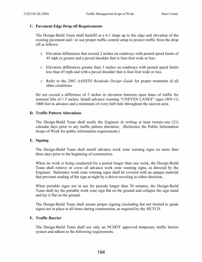
C202185 (B-2500) Traffic Management Scope of Work Dare County
C. Pavement Edge Drop off Requirements
The Design-Build Team shall backfill at a 6:1 slope up to the edge and elevation of the existing pavement and / or use proper traffic control setup to protect traffic from the drop off as follows:
o Elevation differences that exceed 2 inches on roadways with posted speed limits of
45 mph or greater and a paved shoulder that is four-foot wide or less. o Elevation differences greater than 3 inches on roadways with posted speed limits
less than 45 mph and with a paved shoulder that is four-foot wide or less. o Refer to the 2002 AASHTO Roadside Design Guide for proper treatment of all
other conditions.
Do not exceed a difference of 2 inches in elevation between open lanes of traffic for nominal lifts of 1.5 inches. Install advance warning “UNEVEN LANES” signs (W8-11) 1000 feet in advance and a minimum of every half mile throughout the uneven area.
D. Traffic Pattern Alterations
The Design-Build Team shall notify the Engineer in writing at least twenty-one (21) calendar days prior to any traffic pattern alteration. (Reference the Public Information Scope of Work for public information requirements.)
E. Signing The Design-Build Team shall install advance work zone warning signs no more than three days prior to the beginning of construction. When no work is being conducted for a period longer than one week, the Design-Build Team shall remove or cover all advance work zone warning signs, as directed by the Engineer. Stationary work zone warning signs shall be covered with an opaque material that prevents reading of the sign at night by a driver traveling in either direction. When portable signs not in use for periods longer than 30 minutes, the Design-Build Team shall lay the portable work zone sign flat on the ground and collapse the sign stand and lay it flat on the ground. The Design-Build Team shall ensure proper signing (including but not limited to guide signs) are in place at all times during construction, as required by the MUTCD.
F. Traffic Barrier
The Design-Build Team shall use only an NCDOT approved temporary traffic barrier system and adhere to the following requirements.
194

C202185 (B-2500) Traffic Management Scope of Work Dare County
Install temporary traffic barrier system a maximum of two (2) weeks prior to beginning work in any location. Once the temporary traffic barrier system is installed at any location, proceed in a continuous manner to complete the proposed work in that location. Once the temporary traffic barrier system is installed and no work has been or will be performed behind the temporary traffic barrier system for a period longer than two (2) months, remove / reset the temporary traffic barrier system unless the barrier is protecting traffic from a hazard.
Protect the approach end of temporary traffic barrier system at all times during the installation and removal of the barrier by either a truck mounted impact attenuator (maximum 72 hours) or a temporary crash cushion. Protect the approach end of temporary traffic barrier system from oncoming traffic at all times by a temporary crash cushion unless the approach end of temporary traffic barrier system is offset from oncoming traffic as follows:
Posted speed limit (MPH) Minimum offset (feet)
40 or less 15 45 - 50 20
55 25 60 mph or higher 30
Install temporary traffic barrier system with the traffic flow, beginning with the upstream side of traffic. Remove the temporary traffic barrier system against the traffic flow, beginning with the downstream side of traffic. Install drums to close or keep closed tangent sections of the roadway until the temporary traffic barrier system can be placed or after the temporary barrier system has been removed. The distance, in feet, between drums shall be no greater than twice the posted speed limit (MPH). The Design-Build Team shall be responsible for providing proper connection between the existing bridge rails and temporary barrier systems and include this information in the appropriate plans.
G. Traffic Control Devices
The Design-Build Team shall use traffic control devices that conform to all NCDOT requirements and are listed on the Approved Products List. The Approved Products List is shown on NCDOT’s Work Zone Traffic Control website at http://www.ncdot.org/doh/preconstruct/wztc/. The use of any devices that are not shown on the Approved Product List shall require written approval from the Transportation Program Management Director.
195

C202185 (B-2500) Traffic Management Scope of Work Dare County
In tangent sections, channelizing device spacing shall not exceed a distance in feet equal to twice the posted speed limit. At intersections and driveway radii, channelization devices shall be spaced 10 feet on-center and 3 feet off the edge of an open travelway, when lane closures are not in effect. Skinny drums shall only be allowed as defined in Section 1180 of the 2006 NCDOT Standard Specifications for Roads and Structures.
When a CMS is placed within the clear zone, provide proper delineation and protection for the traveling public.
H. Temporary Pavement Markings, Markers and Delineation
The Design-Build Team shall provide Temporary Pavement Marking Plans that meet the requirements of the RFP and the Guidelines for Preparation of Traffic Control and Pavement Marking Plans for Design-Build Projects. The Design-Build Team shall use pavement marking and marker products that conform to all NCDOT requirements and are listed on the NCDOT Qualified Products List. The list is available at http://www.ncdot.org/doh/preconstruct/traffic/congestion/sign/. The use of any devices that are not shown on the Qualified Products List shall require approval from the Director of the Transportation Program Management Unit.
The Design-Build Team shall install temporary pavement markings and markers in accordance with the NCDOT 2006 Standard Specifications for Roads and Structures, and in accordance with the manufacturer’s procedures and specifications. The Design-Build Team shall install temporary pavement markings that are the same width as existing pavement marking on all roadways.
The Design-Build Team shall install temporary pavement markings and temporary pavement markers on the interim surface or temporary pattern as follows:
Road Marking Marker
All Roads and Minimum of Paint Raised Temporary Existing Structures
Proposed Structures Cold Applied Plastic (Type IV) Raised Temporary The Design-Build Team may use any type of pavement markings on the NCDOT Qualified Products List for temporary pattern. However, the Design-Build Team shall maintain a minimum retroreflectivity for pavement markings on all roads (existing and temporary marking) at all times during construction, as follows:
196

C202185 (B-2500) Traffic Management Scope of Work Dare County
White: 125 mcd / lux / m2 Yellow: 100 mcd / lux / m2
When using Cold Applied Plastic (Type IV) pavement markings, place temporary raised markers half on and half off edgelines and centerlines to help secure the tape to the roadway. Markers shall be spaced the appropriate distance apart as described by the 2006 Roadway Standard Drawing 1250.01, Sheet 1 of 3. Place at least 2 applications of paint for a temporary traffic pattern that will remain in place over three (3) months. Tie proposed pavement marking lines to existing pavement marking lines. Replace any pavement markings that have been damaged by the end of each day's operation.
The Design-Build Team shall not place temporary markings on any final asphalt pavement surface unless the temporary markings are placed in the exact location of the final pavement marking. The Design-Build Team shall remove all conflicting markings or markers prior to shifting traffic to a new pattern. Unless noted otherwise in this RFP, removal of the temporary pavement markings on asphalt surfaces shall be accomplished by an NCDOT approved system to minimize damage to the road surface. All temporary pavement markings on concrete pavement shall be removed by water blasting. Temporary pavement markings shall not be obliterated with any type of Black Pavement Markings (paint or other material). The Design-Build Team shall remove all temporary pavement markings without removing more than 1/32-inch of the pavement surface.
I. Temporary Traffic Signals
• Temporary Traffic Signals are not anticipated on this project.
J. Miscellaneous Provide portable temporary lighting to conduct night work in accordance with the NCDOT 2006 Standard Specifications for Roads and Structures. Reference the Record of Decision Project Commitments for coordination of lighting work prior to implementation. Provide proper drainage for all temporary alignments and / or traffic shifts.
The Design-Build Team shall be responsible for coordinating with the law enforcement agency if they will be used. The Staging Concept shall address when law enforcement will be used, where they will be used, duration and why. The Design-Build Team shall
197

C202185 (B-2500) Traffic Management Scope of Work Dare County
only utilize officers who are outfitted with law enforcement uniforms and marked vehicles, which are equipped with proper lights mounted on top of the vehicle and agency emblems. A $250 speeding penalty ordinance will not be approved for this project.
The Design-Build Team shall be responsible for all required temporary shoring, including but not limited to providing, installing, maintaining and removing. Temporary shoring for the maintenance of traffic is defined as shoring necessary to provide lateral support to the side of an excavation or embankment parallel to an open travelway when a theoretical 2:1 (H:V) slope from the bottom of the excavation or embankment intersects the existing ground line closer than 5 feet from the edge of pavement of the open travelway. The Design-Build Team shall identify locations where “temporary shoring for maintenance of traffic” will be required on the Traffic Control Staging Concept. The Design-Build Team shall install temporary traffic barrier as shown on a detail available from the Work Zone Traffic Control Section. This detail provides design information on the temporary traffic barrier location in relation to the temporary shoring and traffic location. The NCDOT Geotechnical Engineering Unit and Work Zone Traffic Control Section websites have more information on temporary shoring. (Notes related to Temporary Shoring are not required in the General Notes sheet for the Traffic Management Plan)
http://www.ncdot.org/doh/preconstruct/highway/geotech/formdet/standards.html http://www.ncdot.org/doh/preconstruct/wztc/DesRes/English/TemporaryShoring/TempShoring.pdf
The Design-Build Team shall adhere to the additional shoring requirements located on the Work Zone Traffic Control Section and Geotechnical Engineering Unit websites. The Design-Build Team shall identify on the appropriate traffic control detail where temporary shoring will be used by providing station limits, offsets, the type of shoring and where temporary traffic barrier will be located if needed.
198
C202185 (B-2500) Pavement Markings Scope of Work Dare County
PAVEMENT MARKINGS SCOPE OF WORK (10-19-2010) General The Design-Build Team shall prepare Final Pavement Marking Plans in accordance with the latest edition of the Manual on Uniform Traffic Control Devices (MUTCD), the NCDOT Roadway Standard Drawings (July 2006), “Guidelines for Preparation of Traffic Control and Pavement Marking Plans for Design-Build Projects”, and the “Design-Build Submittal Guidelines” and the contract requirements contained herein. Final Pavement Marking Plan Requirements The Design-Build Team shall select a Private Engineering Firm (PEF) that has experience designing and sealing Pavement Marking Plans for NCDOT on comparable projects. The Design-Build Team shall develop Pavement Marking Plans that maintain all types of traffic (motorists, bicyclists, and pedestrians within the highway, including persons with disabilities in accordance with the Americans with Disabilities Act of 1990 (ADA), Title II, Paragraph 35.130) as defined by the Manual for Uniform Traffic Control Devices (MUTCD). Pavement Markings, Markers and Delineation
The Design-Build Team shall not place any final pavement markings and markers until the Final Pavement Marking Plans have been accepted by the Department. The Design-Build Team shall use pavement marking, marker, and other delineation products that conform to all NCDOT requirements and are listed on the NCDOT Approved Products List. The use of any devices that are not shown on the Approved Product List shall require written approval from the Signing and Delineation Unit. The Design-Build Team shall install pavement markings and markers in accordance with the NCDOT 2006 Standard Specifications for Roads and Structures, and in accordance with the manufacturer’s procedures and specifications. The Design-Build Team shall install polyurea with highly reflective elements for pavement markings and permanent raised pavement markers. Use water blasting or grinding to remove all residue and surface laitance on concrete surface prior to placing pavement marking materials. The Design-Build Team shall tie proposed pavement marking lines to existing pavement marking lines. The Design-Build Team shall replace any pavement markings that have been damaged by the end of each day’s operation.
199

C202185 (B-2500) Utilities Scope of Work Dare County
UTILITIES COORDINATION SCOPE OF WORK (06-05-11) The Design-Build Team shall obtain the services of a Private Engineering Firm (PEF) knowledgeable in the NCDOT Utility Coordination Process involved with utility relocation / installation and highway construction. The Design-Build Team shall be responsible for coordinating all utility relocations, removals, and / or adjustments where the Design-Build Team and Utility Company, with concurrence from the Department, determine that such work is essential for highway safety and performance of the required highway construction. Coordination shall be for all utilities whether or not they are specifically identified in this scope of work and shall include any necessary utility agreements when applicable. NCDOT will be the approving authority for all utility agreements and approval of plans. Cost Responsibility The Design-Build Team shall be responsible for all costs associated with relocating water and sewer facilities. Reference the Utilities on Structure section of this scope of work for other Design-Build Team cost responsibilities related to attaching 115kV transmission lines and a fiber optic phone line to the new bridge. For any unknown utilities (defined as those utilities not identified in this scope of work) or the portion of known utilities off the new structure, the NCDOT will be responsible for all other non-betterment utility relocation cost when the utility company has prior rights of way / compensable interest. The utility company shall be responsible for the relocation costs if they can not furnish evidence of prior rights of way or a compensable interest in their facilities. The Design-Build Team shall be responsible for determining the cost responsibility for the utility relocations. The Design-Build Team shall be responsible for all costs associated with utility relocations due to haul roads and / or any other temporary conditions resulting from the Design-Build Team’s methods of operation or sequence of work. NCDOT will be the approving authority for all utility agreements and approval of plans Project Details The Design-Build Team shall be responsible for verifying the utility locations, type of facilities, and identifying the utility owners in order to coordinate the relocation of any utilities, known and unknown, in conflict with the project. The following utilities are known to be located within the project construction limits:
Utility Owner Utility Type Cost Responsibility Cape Hatteras EMC Power Utility Owner
Dominion Power Power NCDOT Century-Link Telephone Phone Utility Owner
National Park Service Water Line NCDOT
200

C202185 (B-2500) Utilities Scope of Work Dare County
Water If the Design-Build Team's design and / or construction require the relocation of existing water, designs shall be coordinated with the NCDOT Utility Coordination Unit. All costs associated with the design and construction for relocation of the existing water facility shall be the responsibility of the Design-Build Team and shall be included in the lump sum bid for the project. The Design-Build Team shall develop designs; prepare all plans for needed agreements and permits; submit permits directly to the agencies and obtain approval from the agencies. The Design-Build Team shall be responsible for all permit fees. Designs shall be coordinated with the NCDOT Utility Coordination Unit. The Design-Build Team shall be responsible for submitting five (5) sets of 11 x 17 utility construction drawings to the State Utility Agent, via the Transportation Program Management Director, for further handling. Each set shall include a title sheet, plan sheets, profiles and special provisions if required. Once approved by the State Utility Agent, the plans, with the appropriate agreement, will be sent out to National Park Service for their review and concurrence. The relocation of all water facilities shall be done in accordance with the NCDOT policies and to the National Park Service specifications. In the event of conflicting design parameters in the requirements noted above, the proposed design shall adhere to the most conservative values * National Park Service has a water-line located near the northern bridge termini supplying water to the Oregon Inlet Marina and Fishing Center. If possible, the Design Build Team shall avoid impacting this water-line as part of their overall design. An existing sanitary sewer nitrification field is located off the existing NCDOT right-of-way near the northwest end of the existing bridge. This nitrification field is part of the sanitary sewer system which serves the Oregon Inlet Marina & Fishing Center, adjacent to the existing bridge. The Design-Build Team shall be responsible for assessing the impact of their design as well as construction activities on the existing nitrification field. If possible, the Design Build Team shall avoid impacting this sanitary sewer nitrification field as part of their overall design. The Department will be responsible for any NEPA work that may be required for the relocation of this field, as well as all permitting and relocation work. Utilities on Structure The Department has agreed to allow the Cape Hatteras EMC 115kV transmission lines and the Century Link telephone line on the new bridge as well as providing each company space for one additional future line. These lines shall be interior to any segmental box sections of the structure and will be installed in an interior bay location for girder sections of the structure. All hardware used to hang utilities on the exterior of the structure shall be stainless steel and the utilities shall be protected from rising salt spray to the greatest extent practicable.
201

C202185 (B-2500) Utilities Scope of Work Dare County
Utility attachment plans will require review and approval from each utility owner and this review will be conducted within one month of submittal of these plans to the owners. The Design-Build Team shall be responsible for the design, supply and installation of all attachments, hardware, conduit, and appurtenances required for the utility owners to place the 115kV transmission lines and fiber optic phone lines on the bridge. Transmission Lines Cape Hatteras EMC will supply the necessary cable (750 conductor size) and pulling specifications, if any, for the transmission line to the Design-Build Team and the Design-Build Team shall be responsible for pulling the cable. The Design-Build Team shall subcontract a qualified subcontractor to conduct this pull. Cape Hatteras EMC will have a representative on site during this operation. Cape Hatteras EMC will perform all electrical work necessary to tie in the new lines into existing (splices, terminations, etc.). In regards to the deck trench detail that was provided by Cape Hatteras EMC at the May 4th utility owner meetings, the Department has discussed this detail further with Cape Hatteras EMC and both parties agree that the deck trench is not an acceptable location for the transmission lines. Appropriate safety shielding and warnings for the 115kV transmission lines will be required for all portions of the structure to protect inspection and maintenance personnel. The riser pole owned by Cape Hatteras EMC near the south end of the existing structure should be avoided if possible due to the likelihood of an unacceptable interruption duration due to moving the pole and the unique materials that exist at this site. For any scheduled interruptions of service that are required for this project there is a moratorium for service interruptions from Memorial Day through Labor Day. The preferred time for cutover service interruptions is from March 1 through May 15 and will require a minimum of three weeks notice to the appropriate Utility Company. Phone Line The Design-Build Team shall be responsible for supplying one 4-inch conduit for the full length of the structure to accommodate both the existing fiber optic phone line and one future line. Century Link will remove their cable from the existing structure. The Design-Build Team shall remove and dispose of all other existing cable and appurtenances. The Design-Build Team will not be responsible for the supply or the pulling of the fiber optic phone line for Century Link. Three splice points shall be provided at roughly equal spacing no greater than 4,000 to 5,000 feet apart.
202

C202185 (B-2500) Utilities Scope of Work Dare County
Ample room shall be afforded to place a splice closure and fifty feet of slack coil of fiber at each splice point. Access to a ground shall be provided at each splice point. Utility Relocation Plans In the event of a utility conflict, the Design-Build Team shall request that the utility company submit relocation plans (Highway Construction Plans to be provided by the Design-Build Team to Utility Owners) that show existing utilities and proposed utility relocations for approval by the NCDOT. The Design-Build Team shall submit (3) three copies of the Utility Relocation Plans to the NCDOT State Utility Agent, via the Transportation Program Management Director, for review and approval prior to relocation work beginning. The Design-Build Team shall also be responsible for submitting the appropriate agreements to be used with the Utility Relocation Plans for the portions of the phone and transmission lines located off the new structure (See Agreements found elsewhere in this scope of work). After the review process is complete, the NCDOT Utility Coordination Unit will submit one (1) copy of the Utility Relocation Plans, executed agreements and any necessary comments back to the Design-Build Team. The NCDOT Utility Coordination Unit will also submit a copy of the approved Utility Relocation Plans to the Department’s Resident Engineer. If the Utility Relocation Plans are approved subject to changes, it shall be the Design-Build Team’s responsibility to coordinate these changes with the appropriate utility company. Compensable Interest Typically, affidavits, recorded easements or NCDOT agreements can serve as evidence of prior rights. A compensable interest is identified as follows:
(A) Existing or prior easement rights within the limits of the project, either by recorded right of way or adverse possession (Utility occupying the same location for twenty (20) plus years outside the existing highway rights of way).
(B) Entities covered under General Statute 136-27.1 and 136-27.2. Statute requires
the NCDOT to pay the non-betterment cost for certain water, sewer and gas relocations.
(C) Utilities that have a joint-use agreement that constitutes a compensable interest
with entities that have existing or prior easements rights within the project limits. Work Performed by Design-Build Team for Utility Owners If the Design-Build Team elects to make arrangements with a Governmental Agency or any other utility owner for proposed utility construction, in which the Agency / Utility Owner shall be responsible for the costs of work to be performed by the Design-Build Team, the Design-
203

C202185 (B-2500) Utilities Scope of Work Dare County
Build Team shall be responsible for negotiating all costs associated with the proposed construction. Once the Design-Build Team and the Agency / Utility Owner agree on a plan and a lump sum estimated cost for the utility construction, the Design-Build Team shall be responsible for submitting five (5) sets of 11 x 17 utility construction drawings to the State Utility Agent, via the Transportation Program Management Director, for further handling. Each set shall include a title sheet, plan sheets, profiles and special provisions if required. Also, a letter from the Agency / Utility Owner agreeing to the plans and lump sum cost must accompany this package. The NCDOT will reimburse the Design-Build Team the estimated lump sum cost under a Supplemental Agreement. The necessary Utility Agreement to the Agency / Utility Owner for reimbursement shall be a two party agreement between the NCDOT and the Agency / Utility Owner; and will be developed and executed by the Department. If the Design-Build Team is requested, in writing, by a utility company to relocate facilities not impacted by the project's construction, and / or upgrade or incorporate new facilities as part of the highway construction, designs shall be coordinated with the Utility Owner and NCDOT Utility Coordination Unit. The associated design and construction costs shall be negotiated and agreed upon between the Design-Build Team and the utility company. The Design-Build Team shall develop designs; prepare all plans for needed agreements and permits; submit permits directly to the agencies and obtain approval from the agencies. The Design-Build Team shall be responsible for all permit fees. Communication Cables/Electrical Services for ITS Devices: Prior to establishing the location for new meter poles, the Design Build Team shall coordinate with the local Power Distribution company concerning accessibility of E/C service and safety in maintenance of the meter. All service taps that require a parallel installation within the C/A shall require plans for review and approval by the NCDOT prior to installation. Preferably, parallel service installations within a C/A shall be buried and located as close to the R/W line as practical. However, due to unusual circumstances the NCDOT may approve aerial installations. The Design Build Team shall be responsible for any cost concerning service taps provided by the utility company. Requirements for attachments to proposed structures
(A) No attachments shall be allowed below the bottom of the beams and / or girders.
(B) Drilling of, or attachments to, beams and / or girders shall not be allowed.
(C) A minimum of 18” of clearance to beams and / or girders shall be maintained if possible.
General
204

C202185 (B-2500) Utilities Scope of Work Dare County
The Design-Build Team shall not commence work at points where the highway construction operations are adjacent to utility facilities, until making arrangements with the utility company to protect against damage that might result in expense, loss, disruption of service or other undue inconvenience to the public or utility owner. The Design-Build Team shall be responsible for damage to the existing or relocated utilities resulting from the Team’s operations. In the event of interruption of any utilities by the project construction, the Design-Build Team shall promptly notify the proper authority (Utility Company) and cooperate with the authority in the prompt restoration of service. The Design-Build Team shall accommodate utility adjustments, reconstruction, new installation and routine maintenance work that may be underway or take place during the progress of the contract. The Design-Build Team shall be required to use the guidelines as set forth in the following:
(A) NCDOT Utility Manual - Policies & Procedures for Accommodating Utilities on Highway Rights of Way
(B) Federal Aid Policy Guide - Subchapter G, Part 645, Subparts A & B
(C) Federal Highway Administration’s Program Guide, Utility Adjustments &
Accommodations on Federal Aid Highway Projects
(D) NCDOT Construction Manual Section 105-8
(E) NCDOT Right of Way Manual - Chapter 16 Utility Relocations
(F) NCDENR Public Water Supply - Rules governing public water supply
(G) NCDENR Division of Water Quality - Title 15A - Environment and Natural Resources
Agreements The Department will be responsible for the agreements necessary to place the portion of the fiber optic line and the 115kV transmission lines on the new bridge. The Design-Build Team shall be responsible for all other utility agreements, including those necessary for the portions of the phone and transmission lines located off the new bridge, in accordance with this scope of work. The NCDOT State Utility Agent must execute approved agreements on Design-Build highway projects. The Utility Relocation Agreements (Cost Agreement) and encroachment agreements are available from the NCDOT Utility Coordination Unit. Reference Pages 59 and 60 of the NCDOT Utility Manual on Policies & Procedures for Accommodating Utilities on Highway Rights of Way for the different types of encroachment agreements available for use.
205

C202185 (B-2500) Utilities Scope of Work Dare County
The Design-Build Team shall be required to utilize the NCDOT Standard Utility Encroachment Agreements as necessary in relocating utilities. The Encroachment Agreements shall be used under the following conditions:
(A) If a utility company is not occupying a valid right of way / compensable interest and the proposed relocation will place the relocated utilities within the existing or proposed highway rights of way.
(B) For all new utility installations within the existing or proposed highway rights of
way. This includes all water, sewer and gas lines owned by entities covered under General Statute 136-27.1 and 136-27.2.
(C) In either case above, the Design-Build Team shall submit 5 copies of the
encroachment plans plus 2 originals and 3 copies of the encroachment agreement to the NCDOT State Utility Agent, via the Transportation Program Management Director, for approval.
206

C202185 (B-2500) Intelligent Transportation Systems Scope of Work Dare County
INTELLIGENT TRANSPORTATION SYSTEMS SCOPE OF WORK (12-18-08) Introduction This ITS Scope of Work requires the design, installation, integration, and testing of one wind speed sensor. The device will be located on the north end of the bridge prior to the bridge deck in a location approved by the Engineer. Provide electrical power to the device and related equipment from either the local utility company or a photovoltaic system (PV system). As an option, the wind sensor may also be placed on the solar array platform provided it is located a minimum of 5 feet above the rail with a lowering device installed for maintenance access. Information from the device shall be communicated to the Division 1 office located at 113 Airport Drive (Suite 100), Edenton, NC. The Design-Build Team shall determine the location of the wind sensor, obtain Engineer’s approval of the location, and install the sensor and all other equipment necessary for the installation and delivery of a fully functional system. The Design-Build Team shall install or arrange for installation of new electrical service or PV system for the successful installation and operation of the device. The Design-Build Team shall be responsible for all costs associated with providing the electrical service or PV system. The Design-Build Team shall furnish and install an approved wireless modem (i.e. Verizon Wireless or approved equivalent), antenna, cables, surge protection, and all other material necessary to establish communications to the field equipment. The Design-Build Team shall coordinate with the service provider, through the Department, to activate the modem. Submit all material for approval prior to installation. The Design-Build Team shall be responsible for the integration of the device with the central system. Upon completion of the work, the Design-Build Team shall demonstrate successful integration and operation of the newly installed device by conducting unit and system tests using approved test plans and procedures. General Requirements Perform all work in accordance with the 2006 North Carolina Department of Transportation (NCDOT) Roadway Standard Drawings and the Standard Specifications. All electrical equipment shall conform to the latest version of the applicable standards of the National Electric Manufacturer's Association (NEMA), the Underwriters' Laboratories, Inc. (UL), the Electronic Industries Association (EIA), the International Municipal Signal Association (IMSA), and the National Electrical Safety Code (NESC). All materials and workmanship shall conform to the requirements of the NESC, standards of the American Society for Testing and Materials (ASTM); American National Standards Institute (ANSI); and any state laws and city codes and ordinances that apply. The Department has a Qualified Products List (QPL) available for the Design-Build Team’s use. The QPL web site is:
207

C202185 (B-2500) Intelligent Transportation Systems Scope of Work Dare County
http://www.ncdot.org/doh/preconstruct/traffic/ITSS/SMS/qpl/ Submittals Provide NCDOT with a minimum of 20 working days for reviews of conformance with this Scope of Work. The Design-Build Team must submit 100% project plans and specifications for approval by the NCDOT. Submittals should be made on half-size plan sheets. Also, submit the following to the Engineer concurrent with the plans and specifications:
• Manufacturer’s warranty information on all devices furnished with each device subsystem. (The information should be presented in an organized manner using ring binders with annotated section dividers.)
• All manuals (user guides, owners’ manuals, etc.) furnished by the manufacturer for all devices used in each device subsystem.
• All software furnished on the project. The Design-Build Team must provide detailed wiring diagrams showing all I/O addressing for each new device installed. Wind Sensor Equipment The Design-Build Team shall provide a remote processing unit (RPU) with the minimum features:
• Cabinet: NEMA 4 Aluminum sized to house RPU and all wind sensor support equipment plus 50% free space for future upgrades,
• Memory: 96MB Minimum, • Analog Inputs: 31 channels with dedicated inputs, • Analog Input Voltage Range: -10V to +10V, • Serial Ports: 10 with selectable 300 to 115 Kbps baud rates, • Serial Port Protocols: selectable EIA-232, RS-422/485 half or full duplex, • Ethernet Port: 1, • USB Ports: 2, • Automatic Reset: watchdog timer, • Operating Voltage: 120VAC, • Operating Temperature: -40 to 70 degrees C, • Operating Humidity Range: 0-95% non-condensing.
The Design-Build Team shall provide an ultrasonic anemometer with heater that meets the
following minimum requirements:
• Corrosion-resistant construction, • Fully wind-tunnel tested and calibrated, • 0.1 m/s wind speed resolution, • 0.1m/s (+/-2%) at 30m/s, +/-3% at 70m/s wind speed accuracy, • 1 degree wind direction resolution, • +/- 2 degrees wind direction accuracy, • 0 to 360 degrees measuring wind speed direction, • 0-160 mph measuring wind speed, • RS-232/485 port,
208

C202185 (B-2500) Intelligent Transportation Systems Scope of Work Dare County
• -50 to 50 degrees C operating temperature. The Design-Build Team shall furnish and install Class 3, 30-foot wood poles as necessary for the installation of wind sensor, RPU cabinet and electrical service. Provide poles of treated southern pine or treated Douglas fir as described in the Standard Specifications for electrical service. The Design-Build Team shall furnish and install a grounding system as required by NCDOT standard drawings and Standard Specifications. The Design-Build Team shall furnish and install ½-inch x 36-inch copper-clad air terminal (Class II), with ½-inch diameter, 28-strand (minimum) Class II, bare copper conductor, routed down pole and attached to the central ground rod for lighting protection. Photovoltaic System The Design-Build Team may elect to provide PV power for the wind sensor system meeting the following minimum requirements:
• Provide UL listed, FM Class I Div II, Groups C&D approved solar modules made in North America with a 20-year minimum factory warranty. The module cables shall be double insulated, sunlight resistant, and rate for 90 degrees Celsius.
• Provide UL listed, FM Class I Div II, Group A,B,C&D approved charge controller with battery charging, load control, and diversion regulation functionalities.
• Provide UL listed AC/DC inverter to convert DC voltage to required AC voltage amplitude and frequency.
• Provide 12 Volts, gel electrolyte, non-spillable, maintenance free batteries rated for operating temperature of -76 degrees F to 140 degrees F.
• Provide NEMA 4X stainless steel cabinet with separate compartments for batteries and electronics.
• Provide PV system (solar modules, mounting pole, mounting hardware, cabinet) to withstand 140 miles per hour (mph) wind speed with 15.7 mph wind gust speed.
• Size the batteries to provide power to the system at full load for five (5) days without being charged.
• The system construction must meet all industry standard practices and the requirements of NEC Article 690.
• Submit PV system design documents (load calculations, battery and module sizing and etc.) for review and acceptance.
Integration The Design-Build Team shall furnish and install necessary software module in the central computer for the integration of the wind sensor system and provide a software license to the Engineer. The central systems shall be configured to automatically poll the wind sensor, display the data, and activate an audible alarm when a programmable threshold value, as determined by the Engineer, is reached and/or exceeded, as well as send emails and pagers messages programmed by the system administrator.
209

C202185 (B-2500) Intelligent Transportation Systems Scope of Work Dare County
Testing The Design-Build Team shall submit a detailed unit and system test plan, as well as notification of intended testing to the Engineer for approval at least 45 working days prior to initiation of any testing, including the identification of all required testing levels for the specific equipment provided. The testing shall not commence until such time that the unit and system test plan is approved by the Engineer. Training Provide two (2) hours of field and two (2) hours of central system training. The field training should address, at a minimum, the following subjects:
• Field components overview, • Field components operation and configuration, • Field component scheduled maintenance.
The central system training should address, at a minimum, the following subjects:
• Field device set up and configuration in the central software, • Software use and configuration.
The Design-Build Team shall provide all training material including, a training outline, proposed dates for training, and three (3) copies of user’s manual and training material handouts to the Engineer for review and approval a minimum of 30 days prior to the proposed training date. 30-Day Observation Period Upon completion of the successful completion of the Unit Test and the System Test, and the correction of all deficiencies, including minor construction items, a 30-day Observation Period will commence. This observation will consist of a 30-day period of normal operations of the new field equipment operating with the central equipment without any failure. The Design-Build Team shall respond to system or component failures (or reported failures) that occur during the 30-day Observation Period within twenty-four (24) hours and correct said failures within forty-eight (48) hours. Failures that impact the central software, anemometer, RPU, or wireless modem for more than forty-eight (48) hours will suspend the 30-day Observation Period beginning at the time when the failure occurred. After the cause of such failure has been corrected, timing of the 30-day Observation Period will resume. System or component failures that necessitate a redesign of any component and failures in any of the major system components (central software, anemometer, RPU, wireless modem) exceeding a total of three (3) occurrences will re-initiate the 30-day Observation Period following the correction of the failing design or devices.
210

C202185 (B-2500) Erosion And Sedimentation Control Scope of Work Dare County
EROSION AND SEDIMENTATION CONTROL SCOPE OF WORK (10-11-10)
The NCDOT REU shall review and accept all Erosion and Sedimentation Control Plans. Clearing & Grubbing and Final Grade Release for Construction (RFC) Erosion Control Plans shall be submitted to all NCDOT Personnel listed in the Design-Build Submittal Guidelines before any land disturbing activities, including clearing and grubbing, can commence. The Design-Build Team shall also provide five additional copies of each submittal that the Department will distribute to the permitting agencies for their information. If the Design-Build Team chooses to perform the work in discrete sections, then a complete set of Clearing & Grubbing and Final Grade RFC Erosion Control Plans shall be submitted, accepted, and distributed as noted above prior to land disturbing activities, including clearing and grubbing, commencing in that section. No land disturbing activities, including clearing and grubbing, shall occur in any location that does not have accepted Clearing & Grubbing and Final Grade RFC Erosion Control Plans. Refer to the most recent version of the NCDENR - Erosion and Sediment Control Planning and Design Manual for erosion control design guidelines not addressed in this Scope of Work.
Erosion and Sedimentation Control Plans shall at a minimum address the following:
I. Complete Set of Plans
A. Clearing and Grubbing Phase
1. Use correct NCDOT symbology 2. Protect existing drainage structure inlets with Rock Inlet Sediment Trap Type ‘A’
(RIST-A), Rock Inlet Sediment Trap Type ‘C’ (RIST-C), Rock Pipe Inlet Sediment Trap Type ‘A’ (PIST-A), etc.
3. Utilize adequate perimeter controls (temporary silt ditches (TSD), temporary silt fence (TSF), etc.)
4. Utilize infiltration basins and rock measures with sediment control stone (Temporary Rock Sediment Dam Type ‘B’ (TRSD-B), Temporary Rock Silt Check Type ‘A’ (TRSC-A), etc.) at drainage outlets
5. Take into account existing topography and show contour lines 6. Show 50-foot Environmentally Sensitive Area (ESA) around Oregon Inlet, Motts
Creek and all jurisdictional streams on Clearing & Grubbing EC Plans only 7. Utilize Temporary Rock Silt Checks Type ‘B’ (TRSC-B) to reduce velocity in
existing ditches with spacing of 250 feet divided by percentage of ditch grade. Also utilize TRSC-B’s in proposed TSD’s and temporary diversions (TD)
8. Protect existing streams; do not place erosion control devices in live streams 9. Provide adequate silt storage for 3600 cubic feet per disturbed acre and sediment
basins shall be sized with surface area equal to 435 square feet per cubic foot per second (cfs) of the peak inflow rate, Q25, using 25-year peak rainfall data (NCDENR - Erosion and Sediment Control Planning and Design Manual or NOAA’s National Weather Service web site http://hdsc.nws.noaa.gov/hdsc/pfds/orb/nc_pfds.html for partial duration (ARI) time series type). A Sediment Basin Designer Spreadsheet will be provided by the NCDOT Roadside Environmental Unit (REU) upon request.
211

C202185 (B-2500) Erosion And Sedimentation Control Scope of Work Dare County
10. Infiltration Basins shall provide adequate silt storage for 1800 cubic feet per disturbed acre with surface area equal to 325 square feet per cubic foot per second (cfs) of the peak inflow rate, Q25, using the 25-year peak rainfall data (NCDENR - Erosion and Sediment Control Planning and Design Manual or NOAA’s National Weather Service web site http://hdsc.nws.noaa.gov/hdsc/pfds/orb/nc_pfds.html for partial duration (ARI) time series type). Infiltration Basin shall be designed to dewater in 3 days or less. An Infiltration Basin Designer Spreadsheet will be provided by the NCDOT Roadside Environmental Unit (REU) upon request.
11. The minimum and maximum length to width ratio of all Sediment Basins shall be 2:1 and 6:1, respectively.
12. Coir Fiber Baffles shall be installed in all silt basins and sediment dams at drainage outlets. For silt basins with a 20-foot or longer length, three Coir Fiber Baffles shall be installed with a spacing of 1/4 the basin length. For silt basins with a length less than 20 feet, a minimum of two Coir Fiber Baffles shall be installed, with a spacing of 1/3 the basin length. The Design-Build Team will not be required to show the individual baffles on the Erosion Control Plans, but shall be required to incorporate the Coir Fiber Baffle Detail on the Erosion Control Plans.
13. Include any culvert and / or pipe construction sequence plan sheets in the Clearing & Grubbing Erosion Control Plans; all pipes 48” or larger, or any combination of pipes that total 48” or more require a construction sequence. Prior to installation of pipes smaller than 48 inches in jurisdictional areas, the Design Build Team shall submit a phasing plan for managing the watercourse to the Resident Engineer for review and acceptance. The phasing plan shall be in accordance with the Best Management Practices for Construction and Maintenance Activities.
14. Incorporate temporary sediment basins into permanent stormwater devices and include a skimmer on the riser 1 foot from bottom of basin if applicable.
15. Utilize Wattles with Polyacrylamide (PAM) in temporary and permanent, existing and proposed ditches at a spacing of 50 ft. in areas where sediment basins are not feasible at drainage outlets, and in areas where sediment basins at drainage outlets cannot be properly sized to surface area and/or sediment storage requirements due to safety concerns, ROW limitations, utility conflicts, or other construction limitations approved by the Roadside Environmental Unit.
B. Final Grade Phase
1. Use correct NCDOT symbology 2. Protect existing and proposed drainage structure inlets with RIST-A, RIST-C,
PIST-A, etc. 3. Utilize adequate perimeter controls (TSD, TSF, etc.) 4. Utilize TRSC-B’s to reduce velocity in existing and proposed ditches with spacing of
250 feet divided by percentage of ditch grade. Also utilize TRSC-B’s in proposed TSD’s and TD’s
5. Utilize temporary slope drains and earth berms at top of fill slopes 5 feet or higher and a fill slope grade of 3:1 or steeper, or where there are superelevations above 0.04 and fills are greater than 3 feet. Maximum slope drain spacing shall be 200 feet.
6. Utilize rock energy dissipater and / or silt basin at outlet of slope drain
212

C202185 (B-2500) Erosion And Sedimentation Control Scope of Work Dare County
7. Devices at all drainage turnouts shall utilize infiltration or sediment control stone (TRSD-B, TRSC-A, etc.) and a spillway with an adequately designed base length to distribute outflow
8. Provide adequate silt storage for 3600 cubic feet per disturbed acre and sediment basins shall be sized with surface area equal to 435 square feet per cubic foot per second (cfs) of the peak inflow rate, Q25, using 25-year peak rainfall data (NCDENR - Erosion and Sediment Control Planning and Design Manual or NOAA’s National Weather Service web site http://hdsc.nws.noaa.gov/hdsc/pfds/orb/nc_pfds.html for partial duration (ARI) time series type). A Sediment Basin Designer Spreadsheet will be provided by NCDOT REU upon request
9. Provide matting for erosion control in all ditch lines where the velocity is greater than 2.0 ft./s, and the shear stress is 1.55 psf or less. For ditch lines with a shear stress above 1.55 psf, Permanent Soil Reinforcement Mat or Rip Rap shall be utilized
10. Provide matting for erosion control on all fill slopes 2:1 or steeper 11. Infiltration Basins shall provide adequate silt storage for 1800 cubic feet per disturbed
acre with surface area equal to 325 square feet per cubic foot per second (cfs) of the peak inflow rate, Q25, using the 25-year peak rainfall data (NCDENR - Erosion and Sediment Control Planning and Design Manual or NOAA’s National Weather Service web site http://hdsc.nws.noaa.gov/hdsc/pfds/orb/nc_pfds.html for partial duration (ARI) time series type). A Sediment Basin Designer Spreadsheet will be provided by the NCDOT Roadside Environmental Unit (REU) upon request
12. The minimum and maximum length to width ratio of all Sediment Basins shall be 2:1 and 6:1, respectively
13. Coir Fiber Baffles shall be installed in all silt basins and sediment dams at drainage outlets. For silt basins with a 20-foot or longer length, three Coir Fiber Baffles shall be installed with a spacing of 1/4 the basin length. For silt basins with a length less than 20 feet, a minimum of two Coir Fiber Baffles shall be installed, with a spacing of 1/3 the basin length. The Design-Build Team will not be required to show the individual baffles on the Erosion Control Plans, but shall be required to incorporate the Coir Fiber Baffle Detail on the Erosion Control Plans
14. Incorporate temporary sediment basins into permanent stormwater devices and include a skimmer on the riser 1 foot from bottom of basin if applicable.
15. Utilize Wattles with Polyacrylamide (PAM) in temporary and permanent, existing and proposed ditches at a spacing of 50 ft. in areas where sediment basins are not feasible at drainage outlets, and in areas where sediment basins at drainage outlets cannot be properly sized to surface area and/or sediment storage requirements due to safety concerns, ROW limitations, utility conflicts, or other construction limitations approved by the Roadside Environmental Unit.
C. Intermediate Phase
Intermediate Erosion Control Plans shall only be required if design modifications and / or site conditions require additional erosion control design or design revisions to the RFC Clearing and Grubbing and / or RFC Final Grade Erosion Control Plans. Intermediate Plans shall be submitted for review and shall be accepted prior to construction of any aspect impacted by the revised erosion control design. For any intermediate phase, comply with Section B, “Final Grade Phase” above.
213

C202185 (B-2500) Erosion And Sedimentation Control Scope of Work Dare County
II. Detail Sheets and Notes
A. Provide project specific special notes and details such as temporary rock silt check type B, coir fiber baffle, skimmer basin, etc.
B. Provide matting summary sheet(s): matting for erosion control and permanent soil reinforcement mat
C. Provide reforestation sheet(s): regular, wetland, streambank and / or buffer showing appropriate species
III. Title Sheet
A. Show correct notes: HQW, ESA, clearing and grubbing, etc. B. Show correct standards for project C. List of standard NCDOT symbology D. Show name and certification number of Level IIIA certified individual responsible for
designing and/or reviewing Erosion and Sedimentation Control Plans
IV. Special Provisions
A. Erosion Control Special Provisions are available at the following website: http://www.ncdot.org/doh/operations/dp_chief_eng/roadside/soil_water/special_provisions/
B. References in Erosion Control Special Provisions from the aforementioned website to Method of Measurement, Basis of Payment, or any other statement regarding direct payment for Erosion & Sediment Control measures shall be disregarded.
C. Erosion Control / Stormwater Certification found elsewhere in this RFP. V. Miscellaneous
A. Plan submittals shall include all pertinent design information required for review, such as design calculations, drainage areas, etc.
B. The NCDOT REU will provide a sample set of Erosion and Sedimentation Control Plans (including any special details or special provisions used by the NCDOT REU) and MicroStation Erosion Control Workspace to the Design-Build Team for reference upon request.
C. Plans shall address any environmental issues raised during the permitting process. D. Sufficient time shall be allowed for the Design-Build Team to make any changes to the
Erosion and Sedimentation Control Plans deemed necessary by the NCDOT REU. E. Temporary access and haul roads, other than public roads, constructed or used in
connection with the project shall be considered a part of the project and addressed in the Erosion and Sedimentation Control Plans.
F. Borrow or waste areas that are part of the project shall require a separate Reclamation Plan, unless the borrow or waste activity is regulated under the Mining Act of 1971, or is a landfill regulated by the Division of Solid Waste Management (NCDENR). The Design-Build Team shall submit the permit number for waste / borrow sites covered by the Mining Act or regulated by DSWM (DENR) concurrently to the Transportation Program Management Director and the Resident Engineer. For Reclamation Procedures, see:
214

C202185 (B-2500) Erosion And Sedimentation Control Scope of Work Dare County
http://www.ncdot.org/doh/operations/dp_chief_eng/roadside/fieldops/downloads/Files/ContractedReclamationProcedures.pdf
G. Whenever the Engineer determines that significant erosion and sedimentation continues
despite the installation of approved protective practices, the Design-Build Team shall be required to and shall take additional protective action.
H. An accepted Erosion and Sedimentation Control Plan does not exempt the Design-Build Team from making every effort to contain sediment onsite.
I. Any Erosion Control Design revisions made during the construction of the project shall be submitted to NCDOT REU by the 15th of the month via the Transportation Program Management Director. At anytime requested by the Engineer or the Roadside Environmental Unit, the Design-Build Team shall provide an updated version of the Erosion and Sedimentation Control Plans for distribution to all parties involved in the construction process.
J. The Design-Build Team shall comply with the North Carolina Administrative Code Title 15 A Department of Environment and Natural Resources Chapter 4, Sediment Control.
K. A pre-design meeting shall take place between the NCDOT REU Soil & Water Engineering Section, the Design Build Team, and any other pertinent NCDOT personnel before any Erosion and Sedimentation Control Designs are submitted to NCDOT REU. Erosion and Sedimentation Control Plan submittals shall only be reviewed and accepted by NCDOT REU after the Erosion Control Pre-Design Meeting. The Design Build Team shall be required to submit a tentative Erosion and Sedimentation Control Plan submittal schedule at the pre-design meeting.
L. At minimum, the Design Build Team shall bring one erosion control plan sheet with a Clearing & Grubbing erosion control design to the Erosion and Sedimentation Control Plan pre-design meeting.
M. All RFC Erosion and Sedimentation Control Plans, including any red line revisions, shall be kept on site at all times throughout the duration of the project.
N. Erosion Control / Stormwater Certification shall be required according to the Project Special Provision found elsewhere in this RFP.
O. Prior to installation of any erosion control devices, the Design-Build Team shall verify boundaries of jurisdictional areas in the field and delineated with Safety Fence or flagging. For guidance on Safety Fence and flagging in jurisdictional areas, see:
http://www.ncdot.org/doh/operations/dp_chief_eng/roadside/fieldops/downloads/
P. Once RFC Erosion and Sedimentation Control Plans are issued, any major design change
or addition, any change that involves calculations, and any addition, deletion, or relocation of a sediment basin shall be submitted to the NCDOT REU for review and acceptance. Minor changes such as moving silt fence, adding or moving temporary ditches (unless adding new runoff flow to a sediment basin), and adding or moving slope drains shall be reviewed by the Engineer in the field.
Q. An alternative to placing soils capable of supporting vegetation on shoulders and fill slopes shall be a 1-inch application of a compost blanket with seed and fertilizer
215

C202185 (B-2500) Erosion And Sedimentation Control Scope of Work Dare County
incorporated into the compost. A Special Provision will be provided to the Design-Build Team if this option is selected.
R. At a minimum, the Design-Build Team shall install Floating Turbidity Curtain around each bridge end bent and construction staging areas in the water on the north and south side approaches. If Turbidity Curtain is required at existing and proposed bridge columns by environmental regulatory agencies, the Design-Build Team shall submit a Turbidity Curtain design for the bridge columns to NCDOT REU for review and acceptance.
EROSION CONTROL LIQUIDATED DAMAGES: The Design-Build Team shall observe and comply with Federal and State Laws, Local Laws, Ordinances, and Regulations; as well as Orders and Decrees of Bodies having any jurisdiction or authority in accordance with Section 107 of the 2006 Standard Specifications for Roads and Structures. The Design-Build Team shall take all reasonable precautions to comply with all regulations of all authorities having jurisdiction over public and private land governing the protection of erosion and sedimentation. Any fines, remediation required or charges levied against the Department for failing to comply with all rules and regulations concerning erosion and sediment control, due to the Design-Build Team’s negligence, carelessness, or failure to implement the Erosion and Sedimentation Control Plan and Specifications; or failure to maintain an approved Storm Water Pollution Prevention Plan (SWPPP), regardless of absence of neglect, shall be deducted from monies due the Design-Build Team. In addition to said fines, remediation required, or charges levied, any associated engineering costs or actions taken by the Department in order for the Department to comply with rules and regulations, as a result of the Design-Build Team’s negligence, carelessness, or failure to implement the Erosion and Sedimentation Control Plan and Specifications; and / or the SWPPP, regardless of absence of neglect, shall be deducted from the monies due to the Design-Build Team.
216

C 202185 (B-2500) Environmental Permits Scope of Work Dare County
ENVIRONMENTAL PERMITS SCOPE OF WORK (6-05-11) General The Department will allow no direct contact between the Design-Build Team and representatives of the environmental agencies, including those from the National Park Service and the US Fish and Wildlife Service. No contact between the Design-Build Team and the environmental agencies will be allowed either by phone, e-mail or in person, without representatives of the Department’s PDEA Branch and/or the DEO present. A representative from the NCDOT Design-Build Office shall be included on all correspondence.
The Department will arrange, for each shortlisted team, a meeting with representatives of the permitting agencies prior to the due date for the submission of Technical and Price Proposals. The discussions and answers provided at these meetings are not contractually binding, but intend to offer the Design-Build Teams an opportunity to inquire as to the permitting process as well as specific team concepts.
The Design-Build Team shall be responsible for preparing all designs and documents needed to obtain all permits for this project (Phase I). If any discussion of future phases of the Selected Alternative, as described in the Record of Decision, is required by the permitting agencies to be included in the permit application for Phase I, the Department will prepare this portion of the narrative.
The Design-Build Team shall be responsible for preparing all documents necessary for the Department to obtain the environmental permits for this project. Permit applications will be needed for: US Army Corps of Engineers Section 404 Permit, US Army Corps of Engineers Section 10 Permit (Rivers and Harbors Act), the NC Department of Environment and Natural Resources (DENR), Division of Water Quality (DWQ) Section 401 Water Quality Certification, Division of Coastal Management (DCM) Coastal Area Management Act (CAMA) Major Development Permit and Dredge and Fill Permit, State Stormwater Permit, and a US Coast Guard Bridge Permit. The Design-Build Team shall prepare a Stormwater Management Plan that documents stormwater control measures to the maximum extent practicable per the Department's existing NPDES Stormwater Permit (NCS000250). The Design-Build Team shall be responsible for preparing all documentation necessary in order for the NCDOT to request modifications to the USFWS and NPS Special Use Permits if necessary (reference the Project Special Provision “Construction Access and Staging”). In addition, the Design-Build Team shall also be responsible for the preparation of all documents for a US Army Corps of Engineers Section 103 Permit (Marine Protection, Research, and Sanctuaries Act) as may be required by the Design-Build Team’s design, construction, or dredge disposal methods. The submittal to, and approval from, the DWQ is required on the project stormwater design plans as a prerequisite to the issuance of the 401 Certification.
Reference the Roadway Scope of Work for additional information regarding Special Use Permits within the Cape Hatteras National Seashore and the Pea Island National Wildlife Refuge.
The Design-Build Team shall not begin ground-disturbing activities, including utility relocation, until the required permits, including the USCG permit, have been issued (this does not include permitted investigative borings covered under a Nationwide Permit #6 or permitted load test
217

C 202185 (B-2500) Environmental Permits Scope of Work Dare County
program work). Reference is made to the Project Special Provisions, “Schedule of Estimated Completion Progress”, “Notice to Proceed” and the Standard Special Provision, “Division One” for limitations on work that can be performed until such time that all above referenced permits are obtained.
The Department has reached concurrence point 4A (Avoidance and Minimization) in the Merger Process used by the environmental agencies and the Department to obtain environmental permits for projects. The Design-Build team shall participate and present information in steps 4B and 4C that are necessary to complete the Merger Process. The Design-Build Team shall follow the appropriate details in the document titled “Merger Process Implementation Team – Merger Process Information” which will be provided to the short-listed teams.
The Department will schedule the 4B (Hydraulic Design Review) and 4C (Permit Impacts Review) meetings. The Design-Build Team shall consider their anticipated schedule of pre-requisite submittals and identify in their Technical Proposal what months they would like the Department to schedule the 4B and 4C meetings, accordingly. Failure on the part of the Design-Build Team to meet the dates, as identified in their Technical Proposal, places all responsibility for associated delays solely in the hands of the Design-Build Team.
The Design-Build Team is bound by the terms of the Record of Decision, whether or not they are expressly outlined in this RFP, and is held accountable for meeting all permit conditions. The Design-Build Team is required to staff any personnel necessary to provide permit compliance.
Major Permit Application Process
It shall be the Design-Build Team's responsibility to acquire information and prepare permit drawings that reflect the impacts and minimization efforts resulting from the Merger 01 Process and as designed. Further it shall be the Design-Build Team’s responsibility to provide these permit impact sheets (drawings) depicting the design and construction details to the Department as part of the permit application. The Design-Build Team shall be responsible for developing the permit application for all jurisdictional impacts. The permit application shall include all utility relocations. The permit application shall consist of, at a minimum, the following:
• Cover Letter • Minutes from the 4B and 4C meetings • Permit drawings • Half-size plans • Completed forms (CAMA, ENG 4345, etc.) appropriate for impacts Unless otherwise noted herein, the Department will re-verify and update, as needed, the required environmental data that expires prior to the completion of the activity causing the impact in the jurisdictional areas. These include, but are not limited to, federally protected species, re-verification of wetland jurisdictional areas, and historic /archaeological sites.
The Department will provide preliminary mapping or aerial photography depicting general areas of roughly 6 foot water depth in which Submerged Aquatic Vegetation is likely. The Department will be responsible for any additional SAV surveys or ground-truthing prior to the application of permits. The limits will be verified by the environmental agencies such that appropriate limits can be reflected in the permit applications.
218

C 202185 (B-2500) Environmental Permits Scope of Work Dare County
A revised Section 7 Consultation may be necessary depending on the Design-Build Team’s final alignment and approach to construction staging and access. The Design-Build Team shall be responsible for assembling all pertinent information for the purpose of both determining the need for a re-initiation of the Section 7 Consultation, and if applicable, the Section 7 Consultation itself. In addition, the Design-Build Team shall draft a letter, for the Project Development & Environmental Analysis Branch’s (PDEA) review and FHWA’s signature, requesting concurrence from the United States Fish and Wildlife Service and the National Marine Fisheries Service, as necessary, to document compliance with Section 7 of the Endangered Species Act for those species requiring such concurrence.
Direct coordination among the Design-Build Team, the Transportation Program Management Director, Resident Engineer, and the Natural Environment Unit (PDEA-NEU) shall be necessary to ensure proper permit application development. Upon completion of the permit application package, the Design-Build Team shall forward the package to the Transportation Program Management Director, Resident Engineer, Division Environmental Officer (DEO) and PDEA-NEU concurrently for review and approval. The Department will subsequently forward the package to the appropriate agencies to have the permit application placed on public notice.
Any temporary construction measures, including de-watering, construction access, etc. shall be addressed in the permit applications. Impacts that result from so-called temporary measures may not be judged to be temporary impacts by the agencies. These issues shall be addressed and reviewed by PDEA-NEU prior to the 4B and 4C meetings and resolved with the agencies during the 4B and 4C meetings.
The Design-Build Team shall clearly indicate the location of, duration, and impacts of haul roads within jurisdictional areas. The Design-Build Team shall also identify all proposed borrow and waste sites. These details shall be included in the permit application data. Further, the Design-Build Team shall describe the methods of construction of all structures. The description of the temporary impacts (haul roads, utility relocations, work bridges, etc.) shall include restoration plans, schedules, and disposal plans. This information shall be included in the permit application. This information shall also be part of the data presented at the 4B and 4C meetings. There shall be particular emphasis on minimizing impacts during the construction of the bridge over Oregon Inlet as well as any work bridges and haul roads necessary for such construction.
The NCDOT hereby commits to ensuring, to the greatest extent possible, that the footprint of the impacts in areas under the jurisdiction of the federal Clean Water Act shall not be increased during the Design-Build effort. All fill material shall be immediately stabilized and maintained to prevent sediment from entering adjacent waters or wetlands. The Design-Build Team shall be responsible for ensuring that the design and construction of the project will not impair the movement of aquatic life.
Receipts of notification to adjacent riparian landowners shall be required as part of the CAMA Major Development Permit and Dredge and Fill Permit application process.
The Design-Build Team shall submit one permit application for the entire project. The Design-Build Team shall not submit multiple applications to develop a “staged permitting” process to expedite construction activities in a phased fashion.
219

C 202185 (B-2500) Environmental Permits Scope of Work Dare County
Requests made for modifications to the permits obtained by the Design-Build Team shall only be allowed if the Engineer determines it to be in the best interest of the Department and will be strongly discouraged. The Design-Build Team shall not take an iterative approach to hydraulic design issues. The design shall be complete prior to permit application.
Major Permit Timeframe
With the exception of the US Coast Guard Permit, the Design-Build Team should expect it to take up to 12 months to accurately and adequately complete all designs necessary for permit application, submit application request to the Department, and obtain approval for the permits from the environmental agencies. Department review time for permit application submittals will not exceed one month. Agency review time will be approximately 120 days from receipt of a “complete” package. No requests for additional contract time or compensation will be allowed if the permits are obtained within this 12-month period. With the exception of location and survey work, permitted investigative borings covered under a Nationwide Permit #6, and permitted load test program work, no mobilization of men, materials, or equipment for site investigation or construction of the project shall occur prior to obtaining the permits (either within the 12-month period or beyond the 12-month period). No work that may be construed as construction work, including off-site fabrication of bridge elements, construction staging, or material acquisition, other than that necessary to perform surveys, geotechnical investigations, or other such activities necessary for design, shall be performed prior to written issuance of the Notice to Proceed for construction. The Department will not honor any requests for additional contract time or compensation, including idle equipment or mobilization or demobilization costs, for the Design-Build Team mobilizing men, materials (or ordering materials), or equipment prior to obtaining all permits. The Department will consider requests for contract time extensions for obtaining the permits only if the Design-Build Team has pursued the work with due diligence, the delay is beyond their control, and the 12-month period has been exceeded. If time were granted it would be only for that time exceeding the 12-month period. This 12-month period is considered to begin on the Date of Availability. Provided no additional permanent hardened structures are used for permanent erosion control beyond a typical end bent and wing walls, a variance from the Coastal Resources Commission is not anticipated in support of the DCM Major Development Permit and Dredge and Fill Permit. The 12 month time period noted above presumes that the application for the Major Development Permit will not require a variance and subsequent petition to the Coastal Resources Commission. In the event that a variance is required, then the above 12 month period will be extended to 16 months. In addition, the 120-day review time noted above will be extended to 180 days.
The Design-Build Team needs to be aware that the timeframes listed above for review by PDEA, NCDWQ, NCDCM, the US Army Corps of Engineers, and the US Coast Guard to review any permit applications begin only after a fully complete and 100% accurate submittal.
The Design-Build Team shall meet with DOT personnel, field representatives from the DCM, and other interested agencies, around the time of the 4C meeting in order to review the project and project commitments. At this time, the US Fish and Wildlife Service shall be afforded the opportunity to meet with key Design-Build Team members and Department employees to provide education on artificial lighting and construction on nearby wildlife habitat and behavior.
220

C 202185 (B-2500) Environmental Permits Scope of Work Dare County
In addition, the Design-Build Team shall attend meetings individually with both the National Park Service and the US Fish and Wildlife Service to address Special Use Permit application requirements and expectations, and again to address permit conditions. The Design-Build Team shall contact PDEA-NEU in order to schedule these field reviews. Every effort shall be made to have this meeting prior to submitting the permit application.
The Design-Build Team shall also meet with representatives from the Department, FHWA, State Historic Preservation Office (SHPO), USFWS, and NPS to provide an opportunity to review and comment on the plans and specifications for the parapet and bridge rail for the proposed bridge, per stipulation II.A of the signed Section 106 Programmatic Agreement (contained within the ROD). This meeting shall be held prior to the Concurrence Point 4B meeting.
US Coast Guard Permit
The Design-Build Team should expect it to take 6 months for the issuance of a US Coast Guard permit after the CAMA Major Development Permit has been received. No requests for additional contract time or compensation will be allowed if the USCG Permit is obtained within this 6-month period. With the exception of location and survey work, permitted investigative borings covered under a Nationwide Permit #6, and permitted load test program work, no mobilization of men, materials, or equipment for site investigation or construction of the project shall occur prior to obtaining the USCG permit (either within the 6-month period or beyond the 6-month period). No work that may be construed as construction work, including off-site fabrication of bridge elements, construction staging, or material acquisition, other than that necessary to perform surveys, geotechnical investigations, or other such activities necessary for design, shall be performed prior to written issuance of the Notice to Proceed for construction. The Department will not honor any requests for additional contract time or compensation, including idle equipment or mobilization or demobilization costs, for the Design-Build Team mobilizing men, materials (or ordering materials), or equipment prior to obtaining all permits. The Department will consider requests for contract time extensions for obtaining the USCG permit only if the Design-Build Team has pursued the work with due diligence, the delay is beyond their control, and the 6-month period has been exceeded. If time were granted it would be only for that time exceeding the 6-month period. Prior to submitting the application for the USACE Section 404 Permit, the Design-Build Team shall meet with the Coast Guard and representatives of the Department to coordinate the requirements associated with the project’s construction activities and schedule. The Design-Build Team shall be required to continue coordination activities with the Coast Guard, through the Department, throughout the project’s duration. As a minimum, the coordination requirements will include the following three distinct phases:
Permit Acquisition – The US Coast Guard must provide public notification to all users of the existing channels of the proposed project in order for the users to provide comments. The Design Build Team shall take the lead to research the names and contact information for these users but the Department will assist as needed. This list of users shall be submitted to the US Coast Guard for their public notification purposes. Prior to, or concurrent with, submitting the US Coast Guard Permit application, the Design-Build Team shall have submitted applications for the US Army Corps of Engineers Section 404
221

C 202185 (B-2500) Environmental Permits Scope of Work Dare County
Permit and Section 10 Permit; the NC Department of Environment and Natural Resources, Division of Water Quality, Section 401 Water Quality Certification, the NC Division of Coastal Management CAMA Major Development Permit and the Dredge and Fill Permit. At the Design-Build Team’s risk, the Coast Guard Permit application may be submitted simultaneously with the US Army Corps of Engineers Sections 404 and 10 Permits, the NC Department of Natural Resources (DENR), Division of Water Quality (DWQ) Section 401 Water Quality Certification and the Division of Coastal Management Major Development Permit. The Design-Build Team is cautioned that comments / conditions of the 404, 401 and / or CAMA Permits may require modifications to the Coast Guard Permit application, resulting in potential delays. No request for additional contract time or compensation will be allowed as a result of these delays. All construction impacts, including but not limited to those associated with work bridges, falsework, staging areas and plans for the proposed bridge, shall be clearly noted and itemized in the US Coast Guard Permit application. The US Coast Guard Permit application shall be submitted to the Transportation Program Management Director. The Department will require 15 business days to review and comment on the application. Once all comments are resolved, the Department will submit the permit application. No construction work may begin prior to receipt of the US Coast Guard Permit.
Construction Phase – Prior to beginning any construction activities on the Bonner Bridge, the Design-Build Team shall provide the Coast Guard a construction schedule for the entire bridge. During construction, the Design-Build Team shall adhere to all of the Federal Bridge Statutes Governing Bridges. These Statutes include, but are not limited to the requirement that the Design-Build Team shall obtain written approval from the Coast Guard for any and all waterway closures, partial closures, or potential obstructions 30 days prior to closure or obstruction. It shall be the Design-Build Team’s responsibility to accommodate all possible navigational access and obtain the aforementioned written approval. The Design-Build Team shall notify, and coordinate with, the Coast Guard regarding all closures or obstructions as early as possible. The Design-Build Team shall concurrently submit all correspondence, including but not limited to closure requests, to the US Coast Guard, the Transportation Program Management Director, and the Resident Engineer.
Regulatory – The Design-Build Team shall be responsible for ensuring that construction occurs in a safe and orderly manner. The Design-Build Team shall be solely responsible for criminal penalties, regulatory fines and liability associated with negligence and / or failure to adhere to the Federal Bridge Statutes Governing Bridges.
Notable Permit Details
The following permit details are highlighted:
Subaquatic Vegetation (SAV) – Any restrictions to work in areas where SAV habitat is present presented in this RFP, NEPA documents, or permits apply equally to all levels (homogenous, sparse, etc.) of SAV presence. It has been determined that SAV habitat is not present south of a transverse line where the proposed alignment, as shown on the Corridor Hearing Map, crosses land at the southern tip of Bodie Island at approximate Station 3585+00 –LREV-. More specifically, this line is defined to extend from
222

C 202185 (B-2500) Environmental Permits Scope of Work Dare County
coordinates 35.78008 by 75.54534 to coordinates 35.78082 by 75.54835. In addition, the B-2500 Photogrammetric SAV Survey provided by letter dated May 24, 2011 denotes several areas as "VOID". Of these areas, the only area that crosses the proposed alignment that has been confirmed as lacking SAV habitat is the slough or creek running adjacent to a line extending from coordinates 35.79135 by 75.54697 to coordinates 35.79406 by 75.54869.
Work trestles installed to traverse SAV habitat shall be of an open-grated variety to maximize sunlight to the underlying vegetation.
Dredging - The Design-Build Team is encouraged to minimize dredging, especially during the spring. Pipeline or clamshell dredging is required for all dredging activities. Hopper dredges are prohibited. Dredging is prohibited in areas where Submerged Aquatic Vegetation habitat is present [Reference 15A NCAC 03I.0101(4)(i) and 15A NCAC 07H.0208(b)(1)]. Disposal of dredged material shall be coordinated with the environmental agencies during the Merger process and resolved prior to the permit application. Unless otherwise approved by the NCDOT and permitting agencies, barge access dredge spoils shall be deposited at new or existing dredge material islands. This requirement does not apply to material resulting from drilled shaft excavation. Additional permits may be required to create a new island. Depending on the disposal location, the material may be subject to beach compatibility and associated sampling rules enforced by the Coastal Resources Commission and conducted by the Design-Build Team. The National Park Service and US Fish and Wildlife Services will not allow the deposition of dredged materials, or a borrow pit, within their respective properties. Unless otherwise approved by the NCDOT and the environmental agencies, any dredging shall be done to a maximum depth of 8 feet.
A moratorium on the disposal of dredged materials to the aforementioned islands is anticipated from April 1st to August 31st of each year. Exceptions to this moratorium will likely be allowed dependent upon nesting activities. The permitting agencies have stated that this moratorium will likely be shortened depending upon the nesting activities occurring at the time. In addition, the Wildlife Resource Commission anticipates that there will be ample areas where nesting is not occurring such that disposal of dredged material can be placed in approved areas throughout the majority of the moratorium period.
Jetting - Jetting of piles shall be done in such a manner as to minimize turbidity and to minimize damage to wetlands and SAVs from jetting and jetting spoils. It is preferred that jetting not be used for work bridge construction. If jetting is intended to be used, the application for the environmental permits shall contain a detailed plan for minimizing disturbance and turbidity that temporarily or permanently results from jetting and/or jetting spoils, a discussion on the need for the jetting and a detailed plan for restoration of jurisdictional areas impacted by jetting or jetting spoils.
Load Test Program – The accepted load test program shall be permitted under a USACE NW#6 and the appropriate DCM authorization and the foundation units to be tested must be removed to the greatest extent practicable and in accordance with all
223

C 202185 (B-2500) Environmental Permits Scope of Work Dare County
permit requirements. Coordination with the USCG, including possible permitting will also be the responsibility of the Design-Build Team.
Barge Access - In addition to the constraints outlined in the Project Special Provision, “Construction Access and Staging,” barges may not be dragged into place.
Haul Roads - Haul roads will not be permitted to be placed within areas where Submerged Aquatic Vegetation habitat is present or in intertidal marsh areas. Coordination of haul road location, placement, materials, and means to minimize erosion and equipment leakage shall be coordinated with the environmental agencies during the Merger process.
Noise Restrictions – Due to the proximity of the campground at the Cape Hatteras
National Seashore, unless otherwise allowed by the Engineer and the National Park Service, no pile strikes shall occur between the hours of 9 pm and 8 am from April 1st to October 10th.
Bridge Demolition and Disposal - Details regarding bridge demolition and disposal
shall be included in the Merger 4B and 4C Meeting discussions and in each permit application package. Details regarding the use of haul roads, work bridges, and/or barges for bridge demolition must be included in this application. Jurisdictional areas and areas of Submerged Aquatic Vegetation habitat must be reflected on the bridge demolition plan. Extreme care shall be exercised in demolition in the areas of SAV habitat.
The Department has coordinated with the NC Division of Marine Fisheries (NCDMF) to
establish and require the use of all acceptable bridge demolition materials in the Artificial Reef Program. Four sites have been identified as Sites AR-130, AR-140, AR-145, and AR-160 on the Artificial Reefs Off Oregon Inlet map provided by the Department. The Design-Build Team shall coordinate a disposal plan with the NCDMF to utilize these sites for disposal of the existing bridge.
The Design-Build Team shall coordinate with the NCDMF, both during planning and
operations, to ensure that the disposal of the bridge conforms to the requirements of the General Permit No. 198500194 as provided by the Department. For the purpose of this permit, the NCDMF is considered the Permittee. No additional permits, including from the Bureau of Ocean Energy, Management, Regulation and Enforcement, are anticipated if the Design-Build Team utilizes sites AR-130, AR-140, and/or AR-145. If Site AR-160 is utilized, the Design-Build Team is responsible for including the bridge disposal details in the CAMA Major Development Permit application. The Design-Build Team will be required for all reporting on disposal as required by the NCDMF.
Sites AR-130 and AR-140 are the top two priorities. Site AR-145 is the next priority site. These three sites are considered to be outside State waters. A minimum of 15% of the structure, measured by deck area, shall go to each of these three sites. The NCDMF will also require that a mix of bridge components go to each site.
224

C 202185 (B-2500) Environmental Permits Scope of Work Dare County
Coordination with the NCDMF shall include, at a minimum, dismantling techniques, material types and quantities, and locations for disposal within each site. A representative from the NCDMF will be required to be present to verify the adherence to these details as well as the maintenance of the minimum vertical clearance above the placed reef material. Representatives from the USACE and USCG may also be monitoring the disposal operations.
The minimum vertical clearance for Sites AR-130, AR-140, and AR-145 is 20 ft. below Mean Lower Low Water as identified on National Ocean Service navigation charts. A vertical clearance of 30 ft., measured as above, is required for Site AR-160.
All types of bridge components, regardless of size, as well as scour countermeasures are
to be disposed at these sites subject to the following restrictions: materials that are not free from petroleum or other hydrocarbons, lead based paint, toxic residues such as mercury and cadmium, free floating materials (e.g. wood, foam, plastics), organic material, and crushed concrete. Aluminum materials may be recycled. Exposed rebar is permitted provided it is not exposed more than 3 inches, whether extending from concrete or adjoining concrete sections. Materials deposited at these sites are not required to be anchored or tethered. Any Ajax that must be removed from the existing bridge and cannot be reused elsewhere due to permit conditions or agency requests shall also be deployed to these sites.
No bridge demolition or bridge disposal moratorium is anticipated. Once the reef
material is placed in conformance with the above requirements, the reef will become the responsibility of the NCDMF.
Wildlife Protection - The Design-Build Team is directed to those project commitments
within the ROD and the Biological Opinion relating to Section 7 of the Endangered Species Act. The Design-Build Team will be required to prepare information required for any event in which NCDOT and FHWA reinitiate Section 7 consultation with the USFWS and NMFS. It is expected that consultation will be reinitiated prior to Concurrence Point 4B and again at Concurrence Point 4C. Consultation may also be reinitiated prior to the demolition of the existing Bonner Bridge or as otherwise outlined within this RFP. The Department will be responsible for the re-survey of the Seabeach Amaranth. Reference the Record of Decision and the Biological Opinion for required guidelines and other requirements to be adhered to in order to protect endangered or threatened species.
Green Island is the property of the National Park Service and is considered important bird breeding and nesting habitat for protected species. Care shall be exercised in the vicinity of this island, especially during dredging operations and navigation of vessels so as not to jeopardize the important function of this island.
Other Permits
NCDOT has completed the application for a Nationwide Permit #6 and Special Use Permit (SUP) for obtaining supplemental borings. Any additional geotechnical investigations or test
225

C 202185 (B-2500) Environmental Permits Scope of Work Dare County
pile installations the Design-Build Team desires to complete prior to, or during, construction shall be permitted under a new Nationwide Permit #6, SUP, and the appropriate DCM authorization. It is the Design-Build Team’s responsibility to prepare the permit application and obtain approval from PDEA. NCDOT will then submit the permit application to the agencies as needed. Oregon Inlet is considered to be High Quality Waters in a sensitive coastal environment. Due to the variety of aquatic life in those waters there has been an in-water moratorium from February 15 through October 31 on the past NW6 permits for the site. It is anticipated that any future NW6 permits will allow borings in open water during the moratorium if performed from equipment that floats completely without contacting the bottom. In such case, any investigation that requires track vehicles or entry where floatation is not possible shall occur after the moratorium (November 1 to February 14).
Mitigation Responsibilities of the Design-Build Team
The Department will be responsible for acquiring compensatory mitigation for unavoidable impacts to wetlands and surface waters due to project construction. This mitigation was based on the impacts identified in the ROD. The Department will also be responsible for securing mitigation for any impacts to SAV habitat.
Any changes proposed by the Design-Build Team to any design or construction details provided to the team by the Department shall be approved by the Department prior to being submitted to the resource agencies for their approval.
Should additional jurisdictional impacts result from revised design/construction details, suitable compensatory mitigation for wetlands and/or streams shall be the sole responsibility of the Design-Build Team. Therefore, it is important to note that additional mitigation shall be approved by the agencies and such approval will require, at a minimum, the preparation and approval of a mitigation plan before permit modification(s) are approved and before construction commences. The Design-Build Team shall identify, at the 4B meeting, any additional impacts anticipated beyond that outlined in the ROD for Phase I.
The Design-Build Team shall analyze any new areas to be impacted that have not been analyzed during the NEPA process and preparation of permit applications. This analysis shall include performing all environmental assessments. These assessments shall require the Design-Build Team to engage the services of a competent environmental consultant to conduct a full environmental investigation to include, but not be limited to, Federally Listed Threatened and Endangered Species, wetlands, streams, avoidance and minimization in jurisdictional areas, compensatory mitigation, FEMA compliance, CAMA consideration and historical, archaeological, and cultural resources surveys in these areas. The environmental consultant shall obtain concurrence through PDEA-NEU from the United States Fish and Wildlife Service and the National Marine Fisheries Service to document compliance with Section 7 of the Endangered Species Act for those species requiring such concurrence. In addition the Design-Build Team shall identify additional mitigation required and the fulfillment of any other requirements that may be imposed by the permitting agencies to obtain the permit modification. Any contract extensions resulting from additional environmental assessments required by the Design-Build Team’s design and/or construction details impacting areas outside those previously analyzed through the NEPA process shall be solely at the discretion of the Department.
226

C 202185 (B-2500) Environmental Permits Scope of Work Dare County
If any staging areas are located outside the study corridor, the Design-Build Team shall be prepared to engage the services of a competent environmental consultant to conduct a full environmental investigation to include, but not be limited to, Federally Listed Threatened and Endangered Species, wetlands, streams, avoidance and minimization in jurisdictional areas, compensatory mitigation, FEMA compliance, CAMA consideration and historical, archaeological, and cultural resources surveys in these areas. If additional staging areas are needed on land owned by the National Park Service as part of the Cape Hatteras National Seashore, the Design-Build Team shall ensure that any NEPA documentation as required by the NPS is completed. To the extent that these staging areas do not occur on property owned by the National Park Service or the Cape Hatteras National Seashore, additional NEPA efforts and inclusion of these staging areas in the environmental permits required by this scope or work are not likely.
Additional Commitments
The NCDOT is committed to incorporating all reasonable and practicable design features to avoid and minimize wetland impacts and to provide full compensatory mitigation of all remaining wetland impacts. Avoidance measures were taken during the planning and NEPA phases and minimization measures were incorporated as part of the preliminary project design. The Design-Build Team shall incorporate these avoidance and minimization features plus any minimization identified during the 4B and 4C process into the design.
All work by the Design-Build Team shall be accomplished in strict compliance with the plans submitted with the Section 404, 10, 103, 401, CAMA, Dredge and Fill, and US Coast Guard permit applications and in compliance with all conditions of the permits and certifications issued by the agencies. The Design-Build Team shall provide each of its contractors and / or agents associated with the construction or maintenance of this project with a copy of the permits.
The Design-Build Team shall strictly adhere to these commitments, as well as others, including but not limited to, those made as part of the ROD, revised Final Section 4(f) Evaluation, and Biological Opinion.
If the Design-Build Team discovers any previously unknown historic or archeological remains while accomplishing the authorized work, they will immediately notify NCDOT Staff Archaeologist and / or NCDOT Project Engineer, as listed below, who will initiate the required State / Federal coordination. In addition, reference Commitment #15 of the Record of Decision. A representative from NCDOT Design-Build Office shall also be notified. All questions regarding these sites should be addressed to Mr. Matthew Wilkerson, NCDOT Archaeology at (919) 707-6089, Mr. Paul J. Mohler, NCDOT Staff Archaeologist at (919) 707-6080, or Mr. Brian Yamamoto, PE, NCDOT Project Engineer (919) 707-6051.
227

C202185 (B-2500) Public Information Scope of Work Dare County
PUBLIC INFORMATION SCOPE OF WORK (10/19/10)
NCDOT will take the lead role on this project and be responsible for a portion of the public information efforts through the Department's Communications Office. The NCDOT responsibilities include:
• Organizing public meetings • Providing media announcements • Soliciting and administering advertisements, as deemed necessary • Mailings to the identified target audiences, including postage.
The Design-Build Team shall coordinate with the Department to promote public awareness for this project. The amount of public involvement required for this project is directly based on the Design-Build Team’s Traffic Control Plan and construction details. The Design-Build Team’s responsibilities shall include:
• Attend and present information at two community workshops during the preconstruction phase of the project. One workshop shall be held in Rodanthe and the other in Manteo.
• Attend and present information at one meeting of the Outer Banks Task Force and another meeting with local government officials at the Department’s discretion. The schedule for these meetings will be at the discretion of the Department.
• If a “Beginning of Construction” meeting for area businesses and residents is held, attending and / or speaking at this event.
• Developing and producing informational print materials for all meetings and workshops, subject to review and approval by the Department.
• Providing details surrounding the impacts to the public • Providing advance notice to the Department of upcoming project impacts • Assisting the Department in the development of the target audience list • Attending and / or speaking at public meetings (in addition to those noted above), • Hand delivery of time sensitive informational materials.
The Design-Build Team shall hold an initial project coordination meeting with NCDOT two months prior to start of construction to discuss project impacts to the public. This information will be used by the Department to create a Public Information Plan. The Design-Build Team shall inform the Department at least 6 weeks in advance of any construction activity that will have significant impact on the public, including, but not limited to, the start of construction, major traffic shifts, road closures, ramp closures, detours, night work and project completion. NCDOT will develop, with the assistance of the Design-Build Team, the specific list of target audiences for this project. The following groups are identified as typical target audiences to receive informational materials:
• Governmental agencies • Municipalities directly affected by construction
228

C202185 (B-2500) Public Information Scope of Work Dare County
• Transportation services • Emergency services • Neighborhood groups and private homes • Industry and businesses • Chamber of Commerce • Individual schools effected by the project • County/City school systems • Any other organization as deemed necessary by the Department.
A web site is not required for this project. The Design-Build Team may elect to host a website for the project. The Design-Build Team shall indicate in their Technical Proposal their intent to utilize a web site for this project. If the Design-Build Team proposes a project web site maintained on a NCDOT server, all web site development must use the current NCDOT web design template and must adhere to current software development, security and technical infrastructure standards. All web site design and implementation shall be coordinated with Mr. Ryan Nolan, Internet Web Content Manager, NCDOT Emerging Technologies. The Design-Build shall discuss in the Technical Proposal their approach to providing the public with communication access to project personnel to inquire as to traffic impacts, including vehicular, boat, and pedestrian, especially during the higher volume summer months.
229

C 202185 (B-2500) Standard Special Provisions Dare County
*** STANDARD SPECIAL PROVISIONS ***
LIABILITY INSURANCE (11-18-08) DB1 G80 Revise the 2006 Standard Specifications as follows: Page 1-68, Article 107-16 is amended to include the following as the first, second, third and fourth paragraphs: The Design-Build Team shall be liable for any losses resulting from a breach of the terms of this contract. The Design-Build Team shall be liable for any losses due to the negligence or willful misconduct of its agents, assigns and employees including any sub-contractors which causes damage to others for which the Department is found liable under the Torts Claims Act, or in the General Courts of Justice, provided the Department provides prompt notice to the Design-Build Team and that the Design-Build Team has an opportunity to defend against such claims. The Design-Build Team shall not be responsible for punitive damages. The Design-Build Team shall at its sole cost and expense obtain and furnish to the Department an original standard ACORD form certificate of insurance evidencing commercial general liability with a limit for bodily injury and property damage in the amount of $5,000,000.00 per occurrence and general aggregate, covering the Design-Build Team from claims or damages for bodily injury, personal injury, or for property damages which may arise from operating under the contract by the employees and agents of the Design-Build Team. The required limit of insurance may be obtained by a single general liability policy or the combination of a general liability and excess liability or umbrella policy. The State of North Carolina shall be named as an additional insured on this commercial general liability policy. The policy may contain the following language as relates to the State as an additional insured: “This insurance with respect to the additional insured applies only to the extent that the additional insured is held liable for your or your agent’s acts or omissions arising out of and in the course of operations performed for the additional insured.” The Design-Build Team shall maintain all legally required insurance coverage, including without limitation, worker’s compensation and vehicle liability, in the amounts required by law. Providing and maintaining adequate insurance coverage is a material obligation of the Design-Build Team and is of the essence of this contract. All such insurance shall meet all laws of the State of North Carolina. Such insurance coverage shall be obtained from companies that are authorized to provide such coverage and that are authorized by the Commissioner of Insurance to do business in North Carolina. The Design-Build Team shall at all times comply with the terms of such insurance policies. Upon execution of the contract, provide evidence of the above insurance requirements to the Engineer.
230

C 202185 (B-2500) Standard Special Provisions Dare County
PLANT AND PEST QUARANTINES (Imported Fire Ant, Gypsy Moth, Witchweed, And Other Noxious Weeds) (3-18-03) DB1 G130
Within Quarantined Area This project may be within a county regulated for plant and/or pests. If the project or any part of the Design-Build Team's operations is located within a quarantined area, thoroughly clean all equipment prior to moving out of the quarantined area. Comply with federal/state regulations by obtaining a certificate or limited permit for any regulated article moving from the quarantined area. Originating in a Quarantined County Obtain a certificate or limited permit issued by the N.C. Department of Agriculture/United States Department of Agriculture. Have the certificate or limited permit accompany the article when it arrives at the project site. Contact Contact the N.C. Department of Agriculture/United States Department of Agriculture at 1-800-206-9333, 919-733-6932, or http://www.ncagr.com/plantind/ to determine those specific project sites located in the quarantined area or for any regulated article used on this project originating in a quarantined county. Regulated Articles Include 1. Soil, sand, gravel, compost, peat, humus, muck, and decomposed manure, separately or with
other articles. This includes movement of articles listed above that may be associated with cut/waste, ditch pulling, and shoulder cutting.
2. Plants with roots including grass sod. 3. Plant crowns and roots. 4. Bulbs, corms, rhizomes, and tubers of ornamental plants. 5. Hay, straw, fodder, and plant litter of any kind. 6. Clearing and grubbing debris. 7. Used agricultural cultivating and harvesting equipment. 8. Used earth-moving equipment. 9. Any other products, articles, or means of conveyance, of any character, if determined by an
inspector to present a hazard of spreading imported fire ant, gypsy moth, witchweed or other noxious weeds.
CONTRACTOR CLAIM SUBMITTAL FORM: (9-16-08) DB1 G140 If the Design-Build Team elects to file a written claim or requests an extension of contract time, it shall be submitted on the Contractor Claim Submittal Form (CCSF) available through the Construction Unit or
http://ncdot.org/doh/operations/dp_chief_eng/constructionunit/formsmanuals/.
231

C 202185 (B-2500) Standard Special Provisions Dare County
GIFTS FROM VENDORS AND CONTRACTORS (12-15-09) DB1 G152 By Executive Order 24, issued by Governor Perdue, and N.C. G.S.§ 133-32, it is unlawful for any vendor or contractor (i.e. architect, bidder, contractor, construction manager, design professional, engineer, landlord, offeror, seller, subcontractor, supplier, or vendor), to make gifts or to give favors to any State employee of the Governor’s Cabinet Agencies (i.e. Administration, Commerce, Correction, Crime Control and Public Safety, Cultural Resources, Environment and Natural Resources, Health and Human Services, Juvenile Justice and Delinquency Prevention, Revenue, Transportation, and the Office of the Governor). This prohibition covers those vendors and contractors who: (1) have a contract with a governmental agency; or (2) have performed under such a contract within the past year; or (3) anticipate bidding on such a contract in the future. For additional information regarding the specific requirements and exemptions, vendors and contractors are encouraged to review Executive Order 24 and G.S. § 133-32. Executive Order 24 also encouraged and invited other State Agencies to implement the requirements and prohibitions of the Executive Order to their agencies. Vendors and contractors should contact other State Agencies to determine if those agencies have adopted Executive Order 24. EMBANKMENTS (5-16-06) (Rev 10-19-10) DB2 R18 Revise the 2006 Standard Specifications for Roads and Structures as follows: Page 2-22, Article 235-3 MATERIALS, amend as follows: Add the following as the second sentence of the first paragraph:
Do not use material meeting the requirements of AASHTO M145 for soil classification A-2-5 and A-5 with a plasticity index (PI) of less than 8 within 12” of the subgrade.
Add the following as the second sentence of the second paragraph:
Aerate and dry material containing moisture content in excess of what is required to achieve embankment stability and specified density.
Page 2-22, Subarticle 235-4(B) Embankment Formation, add the following:
(16) Do not place rock or broken pavement in embankment areas where piles or drilled shaft foundations are to be constructed. This shall include but not be limited to piles and foundations for structures, metal signal poles, overhead sign structures, and high mount lighting.
232

C 202185 (B-2500) Standard Special Provisions Dare County
FLOWABLE FILL (8-21-07) DB3 R30 Description This work consists of all work necessary to place flowable fill in accordance with these provisions, the plans developed by the Design-Build Team and as directed. Materials Provide flowable fill material in accordance with Article 340-2 of the 2006 Standard Specifications for Roads and Structures. Construction Methods Discharge flowable fill material directly from the truck into the space to be filled, or by other approved methods. The mix may be placed full depth or in lifts as site conditions dictate. The Design-Build Team shall provide a method to plug the ends of the existing pipe in order to contain the flowable fill. BRIDGE APPROACH FILLS (10-19-10) DB4 R01
Description Construct bridge approach fills in accordance with the contract. Bridge approach fills include bridge approach fills for sub regional tier bridges and reinforced bridge approach fills. Geotextiles include engineering fabrics and geomembranes. Materials Refer to Division 10 of the Standard Specifications: Item Section Portland Cement Concrete, Class B 1000 Select Material 1016 Subsurface Drainage Materials 1044 Engineering Fabrics 1056 Use Class III or V Select Material for reinforced approach fills and only Class V Select Material (standard size no. 78M stone) for bridge approach fills for sub regional tier bridges. Provide polyvinyl chloride (PVC) plastic drainage pipes, fittings and outlet pipes for subsurface drainage materials for all bridge approach fills. For bridge approach fills for sub regional tier bridges, use Type 1 Engineering Fabric for filter fabric to encase no. 78M stone. For reinforced bridge approach fills, use Type 5 Engineering Fabric for woven fabrics and Type 2 Engineering Fabric and no. 78M stone for drains.
233
C 202185 (B-2500) Standard Special Provisions Dare County
Load, transport, unload and store geomembranes such that they are kept clean and free of damage. Geomembranes with defects, flaws, deterioration or damage will be rejected. Do not unwrap geomembranes until just before installation and do not leave geomembranes exposed for more than 7 days before covering geomembranes with woven fabrics. Use either polyvinyl chloride (PVC), high density polyethylene (HDPE) or linear low density polyethylene (LLDPE) geomembranes. For PVC geomembranes, provide grade PVC30 geomembranes meeting the requirements of ASTM D7176. For HDPE and LLDPE geomembranes, use geomembranes with a nominal thickness of 30 mils meeting the requirements of Geosynthetic Research Institute Standard Specifications GM13 or GM17, respectively. Construction Methods Excavate as necessary for bridge approach fills in accordance with the contract. Notify the Engineer when foundation excavation is complete. Do not place geomembranes or filter fabrics until obtaining approval from the Department of the excavation depth and foundation material. Attach geomembranes or filter fabrics to back of end bent caps and wing walls with adhesives, tapes or other approved methods. Use wire staples as needed to hold filter fabrics in place until covered. Overlap adjacent fabrics a minimum of 18” such that overlaps are parallel to the roadway centerline. Glue or weld geomembrane seams to prevent leakage. Contact the Engineer when existing or future structures such as foundations, pavements, pipes, inlets or utilities will interfere with geotextiles. For reinforced bridge approach fills, place woven fabrics within 2” of locations shown on the plans and in slight tension free of kinks, folds, wrinkles or creases. Place first layer of woven fabric directly on geomembranes with no void or material in between. Install woven fabrics with the machine direction (MD) parallel to the roadway centerline. The MD is the direction of the length or long dimension of the roll. Do not splice or overlap woven fabrics in the MD such that splices or overlaps are perpendicular to the roadway centerline. Install woven fabrics with the orientation, dimensions and number of layers shown on the plans. Wrap woven fabrics as shown on the plans or as directed by the Engineer. For reinforced bridge approach fills, construct 1 ft by 1 ft drains consisting of 4” diameter perforated PVC pipes surrounded by no. 78M stone wrapped in type 2 fabric. For bridge approach fills for sub regional tier bridges, install 4” diameter perforated PVC drainage pipes as shown on the plans. Firmly connect PVC pipes together as needed. Connect perforated pipes to outlet pipes near the back faces of wing walls. Provide drains with positive drainage towards outlets. Place pipe sleeves in or under wing walls for outlet pipes such that positive drainage is maintained. Use sleeves of sufficient strength to withstand wing wall loads. Place select material in 8 to 10 inch thick lifts. Compact Class III Select Material in accordance with Subarticle 235-4(C) of the Standard Specifications. Do not displace or damage fabrics or
234

C 202185 (B-2500) Standard Special Provisions Dare County
drains when placing and compacting select material. End dumping directly on fabrics and drains is not permitted. Do not operate heavy equipment on woven fabrics or drains until they are covered with at least 8” of select material. Replace any damaged fabrics and drains to the satisfaction of the Engineer. Use only hand operated compaction equipment for bridge approach fills for sub regional tier bridges and within 3 ft of end bent cap back or wing walls for reinforced bridge approach fills. At a distance greater than 3 ft for reinforced bridge approach fills, compact select material with at least 4 passes of an 8 – 10 ton vibratory roller. Smooth wheeled or rubber tired rollers are also acceptable for compacting select material. Do not use sheepsfoot, grid rollers or other types of compaction equipment with feet. Use solvent cement for connecting outlet pipes and fittings such as wyes, tees and elbows. Provide connectors for outlet pipes and fittings that are watertight and suitable for gravity flow conditions. All open ends of outlet pipes shall be covered with rodent screens. Connect drains to concrete pads or existing drainage structures at ends of outlet pipes as directed by the Engineer. Construct concrete pads and provide an Ordinary Surface Finish in accordance with Subarticle 825-6(B) of the Standard Specifications. FINE GRADING SUBGRADE, SHOULDERS AND DITCHES (07-21-09) DB5 R001 Revise the 2006 Standard Specifications for Roads and Structures as follows: Page 5-1, Article 500-1 Description, replace the first sentence with the following: Perform the work covered by this section including but not limited to preparing, grading, shaping, manipulating moisture content, and compacting either an unstabilized or stabilized roadbed to a condition suitable for placement of base course, pavement, and shoulders. Page 5-1, Subarticle 500-2(A) General, insert the following as the fifth paragraph: Control the moisture content of the material by drying or adding water. AGGREGATE FOR SOIL-CEMENT BASE (07-18-06) DB5 R15 Revise the 2006 Standard Specifications for Roads and Structures as follows: Page 5-27, Article 542-1. Delete the first sentence and substitute the following:
The work covered by this section consists of constructing and curing a soil-cement base by treating the subgrade, existing subbase, or existing base, or any combination of these materials, by pulverizing, adding portland cement, adding aggregate when required, mixing, wetting, and compacting the mixture to the required density.
235

C 202185 (B-2500) Standard Special Provisions Dare County
Page 5-27, Article 542-2. Add the following:
Item Section Aggregate, Std. Size ABC 1005
Page 5-29, Article 542-7. Add the following after the first paragraph: Prior to spreading cement, aggregate shall be spread at the rate shown in the plans. ASPHALT PAVEMENTS - SUPERPAVE (7-18-06)(Rev 11-16-10) DB6 R01 Revise the 2006 Standard Specifications as follows: Page 6-2, Article 600-9 Measurement and Payment, delete the second paragraph. Page 6-12, Subarticle 609-5(C)2, Required Sampling and Testing Frequencies, first partial paragraph at the top of the page, delete last sentence and add the following:
If the Engineer allows the mix to remain in place, payment will be made in accordance with Article 105-3.
Page 6-12, Subarticle 609-5(C)2, QUALITY CONTROL MINIMUM SAMPLING AND TESTING SCHEDULE
First paragraph, delete and replace with the following.
Sample and test the completed mixture from each mix design per plant per year at the following minimum frequency during mix production:
Second paragraph, delete the fourth sentence, and replace with the following
When daily production of each mix design exceeds 100 tons and a regularly scheduled full test series random sample location for that mix design does not occur during that day’s production, perform at least one partial test series consisting of Items A and B in the schedule below.
Page 6-12, Subarticle 609-5(C)2(c) Maximum Specific Gravity, add after (AASHTO T 209):
or ASTM D 2041 Page 6-13, last line and on page and Page 6-14, Subarticle 609-5(C)(2)(e) Retained Tensile Strength (TSR), add a heading before the first paragraph as follows:
(i) Option 1
236

C 202185 (B-2500) Standard Special Provisions Dare County
Insert the following immediately after the first paragraph:
(ii) Option 2
Mix sampled from truck at plant with one set of specimens prepared by the Contractor and then tested jointly by QA and QC at a mutually agreed upon lab site within the first 7 calendar days after beginning production of each new mix design.
Second paragraph, delete and replace with the following:
Test all TSR specimens required by either option noted above on either a recording test press or a test press that maintains the peak load reading after the specimen has broken. Subarticle 609-5(C)(3) Control Charts, delete the second sentence of the first paragraph and replace with the following:
For mix incorporated into the project, record full test series data from all regularly scheduled random samples or directed samples that replace regularly scheduled random samples, on control charts the same day the test results are obtained.
Page 6-15, Subarticle 609-5(C)(3) Control Charts, first paragraph on this page, delete the last sentence and substitute the following:
Denote the moving average control limits with a dash green line and the individual test limits with a dash red line.
Page 6-15, Subarticle 609-5(C)(3)(a), (b) and (c), replace (a) (b) and (c) with the following:
(a) A change in the binder percentage, aggregate blend, or Gmm is made on the JMF, or,
(b) When the Contractor elects to stop or is required to stop production after one or
two moving average values, respectively, fall outside the moving average limits as outlined in subarticle 609-5(C)6 or,
(c) If failure to stop production after two consecutive moving averages exceed the
moving average limits occurs, but production does stop at a subsequent time, re-establish a new moving average beginning at the actual production stop point.
Page 6-15, Subarticle 609-5(C)(4) Control Limits, replace the first paragraph and the CONTROL LIMITS Table on page 6-16 with the following.
237

C 202185 (B-2500) Standard Special Provisions Dare County
The following are established as control limits for mix production. Apply the individual limits to the individual test results. Control limits for the moving average limits are based on a moving average of the last 4 data points. Apply all control limits to the applicable target source.
CONTROL LIMITS
Mix Control Criteria Target Source Moving Average Limit
Individual Limit
2.36 mm Sieve JMF ±4.0 % ±8.0 % 0.075mm Sieve JMF ±1.5 % ±2.5 % Binder Content JMF ±0.3 % ±0.7 % VTM @ Ndes JMF ±1.0 % ±2.0 % VMA @ Ndes Min. Spec. Limit Min Spec. Limit -1.0% P0.075/ Pbe Ratio 1.0 ±0.4 ±0.8 %Gmm @ Nini Max. Spec. Limit N/A +2.0% TSR Min. Spec. Limit N/A - 15%
Page 6-16, Subarticle 609-5(C)(5) Warning Bands, delete this subarticle in its entirety. Pages 6-16 through 6-19, Subarticle 609-5(C)(6), delete the word "warning" and substitute the words "moving average".
Page 6-16, Subarticle 609-5(C)(6) Corrective Actions, first paragraph, first sentence, delete and replace with the following:
Immediately notify the Engineer when moving averages exceed the moving average limits.
Page 6-17, Subarticle 605-5(C)(6) Corrective Actions, third full paragraph, delete and replace with the following:
Failure to stop production when required due to an individual mix test not meeting the specified requirements will subject all mix from the stop point tonnage to the point when the next individual test is back on or within the moving average limits, or to the tonnage point when production is actually stopped, whichever occurs first, to being considered unacceptable.
Sixth full paragraph, delete the first, second, and third sentence and replace with the following:
Immediately notify the Engineer when any moving average value exceeds the moving average limit. If two consecutive moving average values for any one of the mix control criteria fall outside the moving average limits, cease production of that mix, immediately notify the Engineer of the stoppage, and make adjustments. The Contractor may elect to
238

C 202185 (B-2500) Standard Special Provisions Dare County
stop production after only one moving average value falls outside the moving average limits.
Page 6-18, Subarticle 609-5(C)(6) Corrective Actions second full paragraph, delete and replace with the following:
If the process adjustment improves the property in question such that the moving average after four additional tests is on or within the moving average limits, the Contractor may continue production with no reduction in payment
Page 6-18, Subarticle 605-5(C)(6) Corrective Actions, delete the third and fourth full paragraphs, including the Table for Payment for Mix Produced in the Warning Bands and substitute the following:
If the adjustment does not improve the property in question such that the moving average after four additional individual tests is outside the moving average limits, the mix will be evaluated for acceptance in accordance with Article 105-3. Reduced payment for or removal of the mix in question will be applied starting from the plant sample tonnage at the stop point to the sample tonnage when the moving average is on or within the moving average limits. In addition, any mix that is obviously unacceptable will be rejected for use in the work.
Page 6-19, Subarticle 605-5(C)(6) Corrective Actions, first paragraph, delete and replace with the following:
Failure to stop production and make adjustments when required due to two consecutive moving average values falling outside the moving average limits will subject all mix produced from the stop point tonnage to the tonnage point when the moving average is back on or within the moving average limits or to the tonnage point when production is actually stopped, whichever occurs first, to being considered unacceptable. Remove this material and replace with materials that comply with the Specifications at no additional costs to the Department, unless otherwise approved. Payment will be made for the actual quantities of materials required to replace the removed quantities, not to exceed the original amounts.
Page 6-20, Subarticle 609-5(D)(1) General, delete the third full paragraph, and replace with the following:
Perform the sampling and testing at the minimum test frequencies as specified above. Should the density testing frequency fail to meet the minimum frequency as specified above, all mix without the required density test representation will be considered unsatisfactory. If the Engineer allows the mix to remain in place, payment will be made in accordance with Article 105-3.
Page 6-22, Subarticle 609-5(D)(4) Nuclear Gauge Density Procedures, third paragraph, insert the following as the second sentence:
239

C 202185 (B-2500) Standard Special Provisions Dare County
Determine the Daily Standard Count in the presence of the QA Roadway Technician or QA Nuclear Gauge Technician on days when a control strip is being placed.
Page 6-23, Subarticle 609-5(D)(5) Limited Production Procedure, delete the first paragraph including (a), (b), (c) and substitute the following:
Proceed on limited production when, for the same mix type and on the same contract, one of the following conditions occur (except as noted in the first paragraph below).
(a) Two consecutive failing lots, except on resurfacing* (b) Three consecutive failing lots on resurfacing* (c) Two consecutive failing nuclear control strips.
* Resurfacing is defined as the first new uniform layer placed on an existing pavement.
Page 6-25, Article 609-6 QUALITY ASSURANCE, DENSITY QUALITY ASSURANCE, insert the following items after item (E):
(F) By retesting Quality Control core samples from control strips (either core or nuclear) at a frequency of 100% of the frequency required of the Contractor;
(G) By observing the Contractor perform all standard counts of the Quality Control
nuclear gauge prior to usage each nuclear density testing day; or (H) By any combination of the above
Page 6-28, Subarticle 610-3(A) Mix Design-General, delete the fourth and fifth paragraphs and replace with the following:
Reclaimed Asphalt Pavement (RAP) or Reclaimed Asphalt Shingles (RAS) may be incorporated into asphalt plant mixes in accordance with Article 1012-1 and the following applicable requirements.
Reclaimed asphalt pavement (RAP) may constitute up to 50% of the total material used in recycled mixtures, except for mix Type S 12.5D, Type S 9.5D, and mixtures containing reclaimed asphalt shingle material (RAS). Reclaimed asphalt shingle (RAS) material may constitute up to 6% by weight of total mixture for any mix. When both RAP and RAS are used, do not use a combined percentage of RAS and RAP greater than 20% by weight of total mixture, unless otherwise approved. When the percent of binder contributed from RAS or a combination of RAS and RAP exceeds 20% but not more than 30% of the total binder in the completed mix, the virgin binder PG grade shall be one grade below (both high and low temperature grade) the binder grade specified in Table 610-2 for the mix type, unless otherwise approved. When the percent of binder contributed from RAS or a combination of RAS and RAP exceeds 30% of the total
240
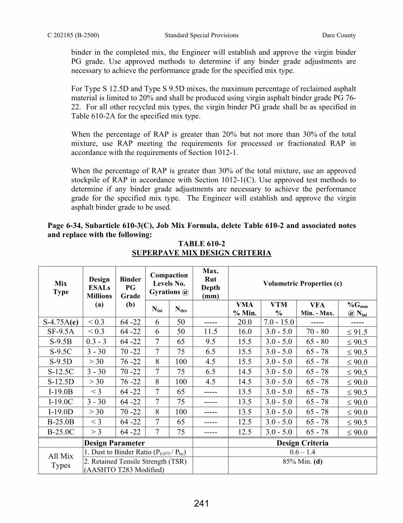
C 202185 (B-2500) Standard Special Provisions Dare County
binder in the completed mix, the Engineer will establish and approve the virgin binder PG grade. Use approved methods to determine if any binder grade adjustments are necessary to achieve the performance grade for the specified mix type. For Type S 12.5D and Type S 9.5D mixes, the maximum percentage of reclaimed asphalt material is limited to 20% and shall be produced using virgin asphalt binder grade PG 76-22. For all other recycled mix types, the virgin binder PG grade shall be as specified in Table 610-2A for the specified mix type. When the percentage of RAP is greater than 20% but not more than 30% of the total mixture, use RAP meeting the requirements for processed or fractionated RAP in accordance with the requirements of Section 1012-1. When the percentage of RAP is greater than 30% of the total mixture, use an approved stockpile of RAP in accordance with Section 1012-1(C). Use approved test methods to determine if any binder grade adjustments are necessary to achieve the performance grade for the specified mix type. The Engineer will establish and approve the virgin asphalt binder grade to be used.
Page 6-34, Subarticle 610-3(C), Job Mix Formula, delete Table 610-2 and associated notes and replace with the following:
TABLE 610-2 SUPERPAVE MIX DESIGN CRITERIA
Compaction Levels No.
Gyrations @
Max. Rut
Depth (mm)
Volumetric Properties (c) Mix Type
Design ESALs
Millions (a)
Binder PG
Grade (b) Nini Ndes VMA
% Min. VTM
% VFA
Min. - Max. %Gmm @ Nini
S-4.75A(e) < 0.3 64 -22 6 50 ----- 20.0 7.0 - 15.0 ----- ----- SF-9.5A < 0.3 64 -22 6 50 11.5 16.0 3.0 - 5.0 70 - 80 ≤ 91.5 S-9.5B 0.3 - 3 64 -22 7 65 9.5 15.5 3.0 - 5.0 65 - 80 ≤ 90.5 S-9.5C 3 - 30 70 -22 7 75 6.5 15.5 3.0 - 5.0 65 - 78 ≤ 90.5 S-9.5D > 30 76 -22 8 100 4.5 15.5 3.0 - 5.0 65 - 78 ≤ 90.0 S-12.5C 3 - 30 70 -22 7 75 6.5 14.5 3.0 - 5.0 65 - 78 ≤ 90.5 S-12.5D > 30 76 -22 8 100 4.5 14.5 3.0 - 5.0 65 - 78 ≤ 90.0 I-19.0B < 3 64 -22 7 65 ----- 13.5 3.0 - 5.0 65 - 78 ≤ 90.5 I-19.0C 3 - 30 64 -22 7 75 ----- 13.5 3.0 - 5.0 65 - 78 ≤ 90.0 I-19.0D > 30 70 -22 8 100 ----- 13.5 3.0 - 5.0 65 - 78 ≤ 90.0 B-25.0B < 3 64 -22 7 65 ----- 12.5 3.0 - 5.0 65 - 78 ≤ 90.5 B-25.0C > 3 64 -22 7 75 ----- 12.5 3.0 - 5.0 65 - 78 ≤ 90.0
Design Parameter Design Criteria 1. Dust to Binder Ratio (P0.075 / Pbe) 0.6 – 1.4 All Mix
Types 2. Retained Tensile Strength (TSR) (AASHTO T283 Modified)
85% Min. (d)
241

C 202185 (B-2500) Standard Special Provisions Dare County
Notes: (a) Based on 20 year design traffic. (b) When Recycled Mixes are used, select the binder grade to be added in accordance
with Subarticle 610-3(A). (c) Volumetric Properties based on specimens compacted to Ndes as modified by the
Department. (d) AASHTO T 283 Modified (No Freeze-Thaw cycle required). TSR for Type S 4.75A, Type B 25.0B, and Type B 25.0C mixes is 80% minimum. (e) Mix Design Criteria for Type S 4.75A may be modified subject to the approval of
the Engineer. Page 6-34, Insert the following immediately after Table 610-2:
TABLE 610-2A SUPERPAVE MIX DESIGN CRITERIA
Percentage of RAP in Mix Category 1 Category 2 Category 3
Mix Type % RAP ≤20% 20.1% ≤ %RAP ≤ 30.0% %RAP > 30.0% All A and B Level
Mixes, I19.0C, B25.0C PG 64 -22 PG 64 -22 TBD
S9.5C, S12.5C, I19.0D PG 70 -22 PG 64-22 TBD S 9.5D and S12.5D PG 76-22 N/A N/A
Note: (1) Category 1 RAP has been processed to a maximum size of 2 inches. (2) Category 2 RAP has been processed to a maximum size of 1 inch by either crushing and or screening to reduce variability in the gradations. (3) Category 3 RAP has been processed to a maximum size of 1 inch, fractionating the RAP into 2 or more sized stockpiles
Page 6-35, Table 610-3 delete and replace with the following:
TABLE 610-3 ASPHALT PLACEMENT- MINIMUM TEMPERATURE REQUIREMENTS
Asphalt Concrete Mix Type Minimum Air Temperature
Minimum Surface Temperature
ACBC, Type B 25.0B, C, B 37.5C 35°F 35°F ACIC, Type I 19.0B, C, D 35°F 35°F ACSC, Type S 4.75A, SF 9.5A, S 9.5B 40°F 50°F* ACSC, Type S 9.5C, S 12.5C 45°F 50°F ACSC, Type S 9.5D, S 12.5D 50°F 50°F
* 35°F if surface is soil or aggregate base for secondary road construction. Page 6-44, Article 610-8 SPREADING AND FINISHING, third full paragraph, replace the first sentence with the following:
242

C 202185 (B-2500) Standard Special Provisions Dare County
Use the 30 foot minimum length mobile grade reference system or the non-contacting laser or sonar type ski with at least four referencing stations mounted on the paver at a minimum length of 24 feet to control the longitudinal profile when placing the initial lanes and all adjacent lanes of all layers, including resurfacing and asphalt in-lays, unless otherwise specified or approved.
Page 6-45, Article 610-8 SPREADING AND FINISHING delete the third paragraph on page 6-45 and replace with the following: Use a Material Transfer Vehicle (MTV) when placing all asphalt concrete plant mix pavements which require the use of asphalt binder grade PG 76-22 and for all types of OGAFC, unless otherwise approved. Use a MTV for all surface mix regardless of binder grade placed on Interstate facilities. Where required above, utilize the MTV when placing all full width travel lanes, collector lanes, ramps, and loops. Page 6-50, Article 610-13 DENSITY ACCEPTANCE, delete the second paragraph and replace with the following:
As an exception, when the first layer of mix is a surface course and is being placed directly on an unprimed aggregate or soil base, the layer will be included in the "Other" construction category.
Page 6-50, Article 610-13 DENSITY ACCEPTANCE, delete the formula and description in the middle of the page and replace with the following:,
PF = 100 – 10(D)1.465 where: PF = Pay Factor (computed to 0.1%)
D = the deficiency of the lot average density, not to exceed 2.0%
Page 6-53, Article 620-4 MEASUREMENT AND PAYMENT, sixth paragraph, delete the last sentence and seventh paragraph, delete the paragraph and replace with the following:
The adjusted contract unit price will then be applied to the theoretical quantity of asphalt binder authorized for use in the plant mix placed during the partial payment period involved, except that where recycled plant mix is used, the adjusted unit price will be applied only to the theoretical number of tons of additional asphalt binder materials required by the job mix formula.
Page 6-54, Article 620-4 MEASUREMENT AND PAYMENT, add the following pay item:
Pay Item Pay Unit Asphalt Binder for Plant Mix, Grade PG 70-28 Ton
243

C 202185 (B-2500) Standard Special Provisions Dare County
Page 6-59, Article 650-5 CONSTRUCTION REQUIREMENTS delete the second paragraph from the bottom of the page beginning “Use a Material Transfer Vehicle (MTV)…” and replace with the following: Use a Material Transfer Vehicle (MTV) when placing all asphalt concrete plant mix pavements which require the use of asphalt binder grade PG 76-22 and for all types of OGAFC, unless otherwise approved. Use a MTV for all surface mix regardless of binder grade placed on Interstate facilities. Where required above, utilize the MTV when placing all full width travel lanes, collector lanes, ramps, and loops. Page 6-69, Table 660-1 MATERIAL APPLICATION RATES AND TEMPERATURES, add the following:
Type of Coat Grade of Asphalt Asphalt Rate
gal/yd2
Application Temperature
oF
Aggregate Size
Aggregate Rate lb./sq. yd.
Total Sand Seal CRS-2 or
CRS-2P 0.22-0.30 150-175 Blotting
Sand 12-15
Page 6-75, Subarticle 660-9(B), Asphalt Seal Coat, add the following as sub-item (5)
(5) Sand Seal
Place the fully required amount of asphalt material in one application and immediately cover with the seal coat aggregate. Uniformly spread the fully required amount of aggregate in one application and correct all non-uniform areas prior to rolling. Immediately after the aggregate has been uniformly spread, perform rolling. When directed, broom excess aggregate material from the surface of the seal coat. When the sand seal is to be constructed for temporary sealing purposes only and will not be used by traffic, other grades of asphalt material meeting the requirements of Articles 1020-6 and 1020-7 may be used in lieu of the grade of asphalt required by Table 660-1 when approved.
Page 6-76, Article 661-1 DESCRIPTION, add the following as the 2nd paragraph:
Provide and conduct the quality control and required testing for acceptance of the UBWC in accordance with Quality Management System for Asphalt Pavements (OGAFC, PADL, and Ultra-Thin HMA Version), included in the contract.
Page 6-76, Article 661-2 MATERIALS, add the following after Asphalt Binder, Grade 70-28:
Item Section Asphalt Binder, Grade 76-22 1020 Reclaimed Asphalt Shingles 1012
244

C 202185 (B-2500) Standard Special Provisions Dare County
Page 6-78, Subarticle 661-2(E), Asphalt Binder For Plant Mix, Grade PG 70-28, rename as ASPHALT BINDER FOR PLANT MIX and add the following as the first paragraph:
Use either PG 70-28 or PG 76-22 binder in the mix design. Where PG 76-22 is being used in the production of Ultra-thin, the grade of asphalt binder to be paid for will be PG 70-28, unless otherwise approved.
Page 6-79, Subarticle 661-2(G), Composition of Mix, add the following as the third sentence of the first paragraph.
The percent of asphalt binder contributed from the RAS shall not exceed 20% of the total binder in the completed mix.
Page 6-80, Article 661-2(G) Composition of Mix, replace Table 661-4 and associated notes with the following:
TABLE 661-4 – MIXTURE DESIGN CRITERIA Gradation Design Criteria (% Passing by Weight)
Standard Sieves 1/2 in. Type A 3/8 in. Type B 1/4 in. Type C ASTM mm (% Passing by Weight) ¾ inch 19.0 100 ½ inch 12.5 85 - 100 100
3/8 inch 9.5 60 - 80 85 - 100 100 #4 4.75 28 - 38 28 – 44 40 - 55 #8 2.36 19 - 32 17 – 34 22 - 32
#16 1.18 15 - 23 13 - 23 15 - 25 #30 0.600 10 - 18 8 - 18 10 - 18 #50 0.300 8 - 13 6 - 13 8 - 13
#100 0.150 6 - 10 4 - 10 6 - 10 #200 0.075 4.0 - 7.0 3.0 - 7.0 4.0 - 7.0
Mix Design Criteria
1/2 in. Type A 3/8 in. Type B 1/4 in. Type C Asphalt Content, % 4.6 - 5.6 4.6 - 5.8 5.0 – 5.8 Draindown Test, AASHTO T 305 0.1% max.
Moisture Sensitivity, AASHTO T 283* 80% min.
Application Rate, lb/ yd2 90 70 50 Approximate Application Depth, in. 3/4 5/8 1/2
Asphalt PG Grade, AASHTO M 320
PG 70-28 or PG 76-22
PG 70-28 or PG 76-22
PG 70-28 or PG 76-22
NOTE: *Specimens for T-283 testing are to be compacted using the SUPERPAVE gyratory compactor. The mixtures shall be compacted using 100 gyrations to achieve specimens approximately 95 mm in height. Use mixture and compaction temperatures recommended by the binder supplier.
245

C 202185 (B-2500) Standard Special Provisions Dare County
Page 6-80, Subarticle 661-3(A) Equipment, add the following as the first paragraph:
Use asphalt mixing plants in accordance with Article 610-5 of the Standard Specifications.
Page 6-82, Subarticle 661-3(C), Application of Ultra-thin Bonded Wearing Course, delete the first paragraph and add the following as the first and second paragraphs.
Use only one asphalt binder PG grade for the entire project, unless the Engineer gives written approval.
Do not place Ultra-thin Bonded Wearing Course between October 31 and April 1, when the pavement surface temperature is less than 50°F or on a wet pavement. In addition, when PG 76-22 binder is used in the JMF, place the wearing course only when the road pavement surface temperature is 60°F or higher and the air temperature in the shade away from artificial heat is 60°F or higher.
Page 10-40, Subarticle 1012-1(A), add the following at the end of the last paragraph, last sentence:
or ultra-thin bonded wearing course. Page 10-41, Table 1012-1, delete the entries for OGAFC and add new entries for OGAFC and a row for UBWC with entries:
Mix Type
Coarse Aggregate
Angularity (b) ASTM D5821
Fine Aggregate Angularity % Minimum
AASHTO T304 Method A
Sand Equivalent % Minimum
AASHTO T176
Flat & Elongated 5:1 Ratio % Maximum
ASTM D4791 Section 8.4
S 9.5 D 100/100 45 50 10 OGAFC 100/100 N/A N/A 10 UBWC 100/85 40 45 10
Delete Note (c) under the Table 1012-1 and replace with the following:
(c) Does not apply to Mix Types SF 9.5A and S 9.5B.
Page 10-42, Subarticle 1012-1(B)(6), add as the last sentence: The percentage loss for aggregate used in UBWC shall be no more than 35%. Page 10-43, Subarticle 1012-1(F): Reclaimed Asphalt Shingle Material (RAS), insert the following immediately following the first paragraph:
246

C 202185 (B-2500) Standard Special Provisions Dare County
(1) Mix Design RAS
Incorporate RAS from stockpiles that have been tested for uniformity of gradation and binder content prior to use in an asphalt mix design.
(2) Mix Production RAS
New Source RAS is defined as acceptable material which was not included in the stockpile when samples were taken for mix design purposes. Process new source RAS so that all materials will pass a 1/2" sieve prior to introduction into the plant mixer unit.
After a stockpile of processed RAS has been sampled and mix designs made from these samples, do not add new source RAS to the original stockpile without prior field testing to insure gradation and binder uniformity. Sample and test new source RAS before blending with the existing stockpile.
Store new source RAS in a separate stockpile until the material can be sampled and tested for comparison with the original recycled mix design data. New source RAS may also be placed against the existing stockpile in a linear manner provided it is sampled for mix design conformity prior to its use in the recycled mix. RAS contamination including but not limited to excessive dirt, debris, clean stone, concrete will not be allowed.
Field approval of new source RAS will be based on the table below and volumetric mix properties on the mix with the new source RAS included. Provided these tolerances are met, volumetric properties of the new mix will then be performed. If all volumetric mix properties meet the mix design criteria for that mix type, the new source RAS may continue to be used. If the gradation, binder content, or any of the volumetric mix properties are not within the allowable tolerances of the table below, do not use the new source RAS unless approved by the Engineer. The Contractor may elect to either not use the stockpile, to request an adjustment to the JMF, or to redesign the mix.
247
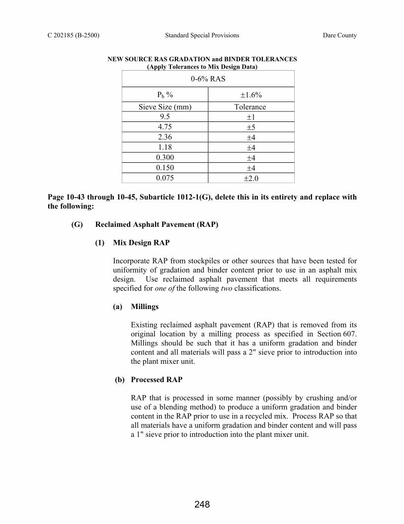
C 202185 (B-2500) Standard Special Provisions Dare County
NEW SOURCE RAS GRADATION and BINDER TOLERANCES
(Apply Tolerances to Mix Design Data)
0-6% RAS
Pb % ±1.6% Sieve Size (mm) Tolerance
9.5 ±1 4.75 ±5 2.36 ±4 1.18 ±4 0.300 ±4 0.150 ±4 0.075 ±2.0
Page 10-43 through 10-45, Subarticle 1012-1(G), delete this in its entirety and replace with the following:
(G) Reclaimed Asphalt Pavement (RAP)
(1) Mix Design RAP
Incorporate RAP from stockpiles or other sources that have been tested for uniformity of gradation and binder content prior to use in an asphalt mix design. Use reclaimed asphalt pavement that meets all requirements specified for one of the following two classifications.
(a) Millings
Existing reclaimed asphalt pavement (RAP) that is removed from its original location by a milling process as specified in Section 607. Millings should be such that it has a uniform gradation and binder content and all materials will pass a 2" sieve prior to introduction into the plant mixer unit.
(b) Processed RAP
RAP that is processed in some manner (possibly by crushing and/or use of a blending method) to produce a uniform gradation and binder content in the RAP prior to use in a recycled mix. Process RAP so that all materials have a uniform gradation and binder content and will pass a 1" sieve prior to introduction into the plant mixer unit.
248

C 202185 (B-2500) Standard Special Provisions Dare County
(c) Fractionated RAP Fractionated RAP is defined as having two or more RAP stockpiles, where the RAP is divided into coarse and fine fractions. Grade RAP so that all materials will pass a 1" sieve. The coarse RAP stockpile shall only contain material retained on a 3/8" screen, unless otherwise approved. The fine RAP stockpile shall only contain material passing the 3/8" screen, unless otherwise approved. The Engineer may allow the Contractor to use an alternate to the 3/8" screen to fractionate the RAP. The maximum percentages of fractionated RAP may be comprised of coarse, fine, or the combination of both. Utilize a separate cold feed bin for each stockpile of fractionated RAP used.
(d) Approved Stockpiled RAP
Approved Stockpiled RAP is defined as fractionated RAP which has been isolated and tested for asphalt content, gradation, and asphalt binder characteristics with the intent to be used in mix designs with greater than 30% RAP materials. Fractionate the RAP in accordance with Section 1012-1(G)(c). Utilize a separate cold feed bin for each approved stockpile of RAP used. Perform extraction tests at a rate of 1 per 1000 tons of RAP, with a minimum of 5 tests per stockpile to determine the asphalt content and gradation. Separate stockpiles of RAP material by fine and coarse fractions. Erect and maintain a sign satisfactory to the Engineer on each stockpile to identify the material. Assure that no deleterious material is allowed in any stockpile. The Engineer may reject by visual inspection any stockpiles that are not kept clean, separated, and free of foreign materials. Submit requests for RAP stockpile approval to the Engineer with the following information at the time of the request: (1) Approximate tons of materials in stockpile (2) Name or Identification number for the stockpile (3) Asphalt binder content and gradation test results (4) Asphalt characteristics of the Stockpile. For the Stockpiled RAP to be considered for approval, the gradation and asphalt content shall be uniform. Individual test results, when compared to the target, will be accepted if within the tolerances listed below:
249

C 202185 (B-2500) Standard Special Provisions Dare County
APPROVED STOCKPILED RAP GRADATION and BINDER TOLERANCES (Apply Tolerances to Mix Design Data)
Pb % ±0.3% Sieve Size (mm) Percent Passing
25.0 ±5% 19.0 ±5% 12.5 ±5% 9.5 ±5% 4.75 ±5% 2.36 ±4% 1.18 ±4% 0.300 ±4% 0.150 ±4% 0.075 ±1.5%
Note: If more than 20% of the individual sieves are out of the gradation
tolerances, or if more than 20% of the asphalt binder content test results fall outside the appropriate tolerances, the RAP shall not be used in HMA unless the RAP representing the failing tests is removed from the stockpile.
Do not add additional material to any approved RAP stockpile, unless otherwise approved by the Engineer.
Maintain at the plant site a record system for all approved RAP stockpiles. Include at a minimum the following: Stockpile identification and a sketch of all stockpile areas at the plant site; all RAP test results (including asphalt content, gradation, and asphalt binder characteristics).
(2) Mix Production RAP
During mix production, use RAP that meets the criteria for one of the following categories:
(a) Mix Design RAP
RAP contained in the mix design stockpiles as described above may be used in all applicable JMFs. These stockpiles have been pretested: however, they are subject to required QC/QA testing in accordance with Subarticle 609-5(C)(2).
(b) New Source RAP
New Source RAP is defined as any acceptable material that was not included in the stockpile or other source when samples were taken for
250

C 202185 (B-2500) Standard Special Provisions Dare County
mix design purposes. Process new source RAP so that all materials have a uniform gradation and binder content and will pass a 2" sieve prior to introduction into the plant mixer unit. After a stockpile of millings, processed RAP, or fractionated RAP has been sampled and mix designs made from these samples, do not add new source RAP to the original stockpile without prior field testing to insure gradation and binder uniformity. Sample and test new source RAP before blending with the existing stockpile.
Store new source RAP in a separate stockpile until the material can be sampled and tested for comparison with the original recycled mix design data. New source RAP may also be placed against the existing stockpile in a linear manner provided it is sampled for mix design conformity prior to its use in the recycled mix. Unprocessed RAP is asphalt material that was not milled and/or has not been processed to obtain a uniform gradation and binder content and is not representative of the RAP used during the applicable mix design. Unprocessed RAP shall not be incorporated into any JMFs prior to processing. Different sources of unprocessed RAP may be stockpiled together provided it is generally free of contamination and will be processed prior to use in a recycled mix. RAP contamination in the form of excessive dirt, debris, clean stone, concrete, etc. will not be allowed. Incidental amounts of dirt, concrete, and clean stone may be acceptable. Unprocessed RAP may be processed and then classified as a new source RAP as described above.
Field approval of new source RAP will be based on Table 1012-2 below and volumetric mix properties on the mix with the new source RAP included. Provided the Table 1012-2 tolerances are met, volumetric properties of the new mix will then be performed. If all volumetric mix properties meet the mix design criteria for that mix type, the new source RAP may continue to be used. If the gradation, binder content, or any of the volumetric mix properties are not within the allowable tolerances of Table 1012-2, do not use the new source RAP unless approved by the Engineer. The Contractor may elect to either not use the stockpile, to request an adjustment to the JMF, or to redesign the mix.
251

C 202185 (B-2500) Standard Special Provisions Dare County
TABLE 1012-2
NEW SOURCE RAP GRADATION and BINDER TOLERANCES (Apply Tolerances to Mix Design Data)
Mix Type
0-20% RAP 20+-30 % RAP 30+ % RAP
Sieve (mm)
Base Inter. Surf. Base Inter. Surf. Base Inter. Surf.
Pb % ± 0.7% ± 0.4% ± 0.3% 25.0 ±10 - - ±7 - - ±5 - - 19.0 ±10 ±10 - ±7 ±7 - ±5 ±5 - 12.5 - ±10 ±10 - ±7 ±7 - ±5 ±5 9.5 - - ±10 - - ±7 - - ±5 4.75 ±10 - ±10 ±7 - ±7 ±5 - ±5 2.36 ±8 ±8 ±8 ±5 ±5 ±5 ±4 ±4 ±4 1.18 ±8 ±8 ±8 ±5 ±5 ±5 ±4 ±4 ±4 0.300 ±8 ±8 ±8 ±5 ±5 ±5 ±4 ±4 ±4 0.150 - - ±8 - - ±5 - - ±4 0.075 ±4 ±4 ±4 ±2 ±2 ±2 ±1.5 ±1.5 ±1.5
ASPHALT PAVEMENTS - WARM MIX ASPHALT SUPERPAVE: (5-19-09) (Rev 01-18-11) DB6 R002 Warm Mix Asphalt (WMA) is defined as additives or processes that allow a reduction in the temperature at which asphalt mixtures are produced and placed. Notify the Engineer at least 2 weeks before producing the WMA so the Engineer can arrange a pre-pave meeting. Discuss special testing requirements necessary for WMA at the pre-pave meeting. Include at the pre-pave meeting the Design-Build Team’s QC manager, Paving Superintendent, and manufacturer’s representative for the WMA technology to be used, the Department’s Roadway Construction Engineer, Resident Engineer, State Pavement Construction Engineer, and Quality Assurance Supervisor. Require a manufacturer's representative for the WMA technology to be present on site at the plant during the initial production and on the roadway during the laydown of the warm mix asphalt.
The requirement for the manufacturer's representative to be present at the pre-pave meeting and on-site at the plant may be waived by the Engineer based on previous work experience with the specific WMA technology used.
If the use of WMA is suspended during production, and the Design-Build Team begins using Hot Mix Asphalt (HMA), then the Design-Build Team shall be required to use HMA for the remainder of the specific route or map unless otherwise approved by the Engineer.
252
C 202185 (B-2500) Standard Special Provisions Dare County
Revise the 2006 Standard Specifications for Roads and Structures as follows: Page 6-8, Article 609-1 Description, insert the following as the second paragraph:
Warm Mix Asphalt (WMA) is defined as additives or processes that allow a reduction in the temperature at which asphalt mixtures are produced and placed. WMA is allowed for use at the Design-Build Team’s option where allowed in the contract documents.
Page 6-9, Article 609-4 Field Verification of Mixture and Job Mix Formula Adjustments,
Second paragraph, insert the following immediately after the first sentence: When producing a WMA, perform field verification testing including Tensile Strength Ratio (TSR) testing in accordance with AASHTO T283 as modified by the Department. Third paragraph, delete the third sentence and replace with the following: Verification is satisfactory for HMA when all volumetric properties except %Gmm@Nini are within the applicable mix design criteria, and the gradation, binder content, and %Gmm@Nini are within the individual limits for the mix type being produced. Verification is satisfactory for WMA when all volumetric properties except %Gmm@Nini are within the applicable mix design criteria, the TSR meets the design criteria, and the gradation, binder content, and %Gmm@Nini are within the individual limits for the mix type being produced.
Page 6-12, Subarticle 609-5(C)2(d) Bulk Specific Gravity of Compacted Specimens, add after (AASHTO T 312):
When producing Warm Mix Asphalt, gyrate specimens to specified Ndes compaction effort without reheating mix other than to desired compaction temperature. Record time needed to reheat samples (if any).
Page 6-14, Subarticle 609-5(C)(2)(e) Tensile Strength Ratio, insert the following immediately after the third paragraph:
When producing WMA, perform TSR testing at i. Prior to initial production for each JMF and ii. Every 15,000 tons.
After three (3) consecutive passing TSR tests for a specific JMF, a request may be submitted to the State Asphalt Design Engineer to revert to the Hot-Mix Asphalt QMS Manual procedures for TSR testing on that JMF. This request shall be submitted in writing and shall include all test result data (Material and Tests Unit Form 612s) performed on the specific JMF.
253

C 202185 (B-2500) Standard Special Provisions Dare County
Page 6-27, Article 610-1 Description, insert the following as the third paragraph:
Warm Mix Asphalt (WMA) is defined as additives or processes that allow a reduction in the temperature at which asphalt mixtures are produced and placed. Use WMA at the Design-Build Team’s option at locations allowed by the contract documents.
Page 6-27, Article 610-2 Materials, insert the following at the end of this Article:
Use only WMA technologies on the allowable routes listed on the Department’s approved list maintained by the Materials and Tests Unit. The Department’s approved list can be found at the following website:
http://www.ncdot.org/doh/operations/materials/pdf/wma.pdf.
Page 6-31, Subarticle 610-3(B) Mix Design-Criteria, add the following as the fifth paragraph:
When WMA is used, submit the mix design without including the WMA additive. Page 6-32, Subarticle 610-3(C) Job Mix Formula, add the following as the second paragraph:
When WMA is used, document the technology used, recommended dosage rate, and the requested plant mix temperature on the JMF submittal. Verify the JMF based on plant produced mixture from the field verification test. Immediately following PG 76-22 335ºF, add the following paragraph: When WMA is used, produce an asphalt mixture within the temperature range of 225°F and 275 °F.
ASPHALT BINDER CONTENT OF ASPHALT PLANT MIXES (10-6-05) DB6 R15 The approximate asphalt binder content of the asphalt concrete plant mixtures used on this project will be as follows:
Asphalt Concrete Base Course Type B 25.0_ 4.4% Asphalt Concrete Intermediate Course Type I 19.0_ 4.8% Asphalt Concrete Surface Course Type S 4.75A 6.8% Asphalt Concrete Surface Course Type SF 9.5A 6.7% Asphalt Concrete Surface Course Type S 9.5_ 6.0% Asphalt Concrete Surface Course Type S 12.5_ 5.5%
The actual asphalt binder content will be established during construction by the CEI firm within the limits established in the 2006 Standard Specifications or Project Special Provisions.
254

C 202185 (B-2500) Standard Special Provisions Dare County
ASPHALT PLANT MIXTURES (07-01-95) DB6 R20 Place asphalt concrete base course material in trench sections with asphalt pavement spreaders made for the purpose or with other equipment approved by the Engineer. BRIDGE DECK RIDEABILITY AND GROOVING General This Special Provision shall govern the testing, diamond grinding, transverse grooving and all other related work associated with obtaining satisfactory rideability and surface texture of the bridge deck surface. Provide a surface finish in accordance with Article 420-14(B) of the Standard Specifications.
Testing Requirements
Perform acceptance testing of the longitudinal profile of the finished bridge deck in each wheel path of each lane in the presence of the Engineer. It is the Design-Build Team’s responsibility to submit a proposed plan of action and schedule for profilograph testing. Use a certified independent provider, approved by the Engineer, to perform the profilograph test.
Prior to profilograph testing, placement of the bridge deck and barrier rail within the section to be tested shall be complete, with the exception of blockouts required for the installation of joints. Do not install joints until the Engineer determines that the rideability requirements herein have been met. Joint locations should be temporarily bridged sufficiently to facilitate operation of the profilograph and corrective equipment across the joint. Remove all obstructions from the bridge deck and sweep the surface clean of debris prior to testing. If automated profilograph equipment is used, there shall be no radio transmissions or other activities that might disrupt the automated profilograph equipment during the testing.
Ensure that the profilograph is in good operating condition per the manufacturer’s recommendations. Maintain tires free of debris and buildup during each test run. Operate the profilograph at a maximum speed of 2 miles per hour (3.2 kph). If a propulsion vehicle is used, it shall be approved, and the gross vehicle weight shall not exceed 1,000 pounds.
At the beginning and end of each day's testing, and at other times determined to be necessary by the Engineer, operate the profilograph over a calibration strip so the Engineer can verify correct operation of the profilograph. The calibration strip shall be a 100 foot section of pavement that is reasonably level and smooth. Submit each day’s calibration graphs with that day’s test section graphs to the Engineer. Calibrate the profilograph in accordance with the current NCDOT procedure entitled "Determination of Profile Index". Copies of this procedure may be obtained from the NCDOT Construction Unit.
Plot each profilogram on a continuous graph at a horizontal scale of 25 feet per inch (0.3 m per mm) with the vertical scale plotted at a true scale. Station numbers shall be recorded on the profilogram at distances not to exceed 200 feet (61.0 m). Note joint locations on the profilogram.
255

C 202185 (B-2500) Standard Special Provisions Dare County
Take profiles with the recording wheel in each wheel path of each lane. The wheel paths of a lane are considered parallel to and approximately 3.5 feet (1.1 m) inside both edges of the travel lane. Take profiles over the entire length of the travel lanes on the bridge deck including approach slabs. Upon completion of testing, submit the profilograms for each wheelpath to the Engineer for analysis. The Engineer will retain the profilograms.
The Engineer will determine the Profile Index for each wheel path in accordance with the procedure entitled "Determination of Profile Index".
A test section is defined as a 600 foot (182.9 m) length of each travel lane. The maximum allowable Profile Index per lane shall not exceed 25” per mile (395 mm per km) as determined with a 0.0” (0.0 mm) blanking band over any 600 foot (182.9 m) test section. The Design-Build Team will correct individual deviations in excess of 0.3” over any 25 foot (7.6 mm in 7.6 m) length on the line tested by diamond grinding. Additionally, the entire deck surface shall meet a 0.125” in 10 feet (3 mm in 3 m) straightedge check made atop the deck either transversely or longitudinally as deemed necessary by the Engineer.
Diamond grinding
If the deck does not meet the testing requirements, diamond grinding is required to make corrections. Diamond grind the full width of all lanes and shoulders in the direction of travel.
When diamond grinding, use either a Boart Longyear PC 5000, a Target 3804 or an approved equal. Submit grinding equipment specifications to the Engineer for approval before any grinding is performed. Use a grinding machine capable of removing a minimum of 3 feet of width with each pass. Multiple passes may be needed to achieve the required depth of removal. In addition, hand grinding may be required to remove vertical steps between passes.
The ground surface shall consist of between 50 and 60 grooves per foot (305 mm) of width. The grooves shall be between 0.09” (2.3 mm) and 0.15” (3.8 mm) in width and 0.0625” (1.6 mm) in depth. The area between the grooves shall be between 0.06” (1.5 mm) and 0.13” (3.3 mm) in width. The final concrete texture shall be uniform.
Construct and operate the grinding machine such that it will not cause strain or damage to the deck surface, excessive ravels, aggregate fractures, spalls, or disturbance of transverse joints. Longitudinally grind the deck parallel to the roadway centerline.
Continuously remove all slurry or other debris resulting from the grinding operations by vacuum pick-up or other approved methods. Prevent the slurry from flowing into floor drains, onto the ground or into the body of water under the bridge. Dispose of all residues off the project.
In completing all corrective work on the deck surface to satisfy the rideability criteria stated herein, limit grinding such that the final reinforcement cover is not less than the plan cover minus ½” (12mm). In cases where this cannot be achieved, other corrective work may be required as directed by the Engineer.
Provide additional profilograph testing as necessary following grinding until the rideability requirements above are satisfied.
256

C 202185 (B-2500) Standard Special Provisions Dare County
Grooving Bridge Floors After the concrete surface profile has been accepted by the Engineer, the concrete blockouts poured, and the joints installed, groove the bridge deck in accordance with Subarticle 420-14(B) of the Standard Specifications. If a substantial amount of bridge deck surface has been diamond ground and/or the concrete cover over the slab reinforcement has been reduced to the minimum, the Engineer may delete all or a portion of the requirement of grooving in that area.
SUBSURFACE DRAINAGE (7-20-10) DB8 R05 Revise the 2006 Standard Specifications for Roads and Structures as follows: Page 8-13, Delete Section 815 SUBSURFACE DRAINAGE and replace it with the following: Description The Design-Build Team shall construct subsurface drains, underdrains, blind drains and other types of drains where groundwater is within 6 feet of subgrade. Install markers to locate concrete pads for drains. This provision does not apply to shoulder drains. Materials Refer to Division 10 of the Standard Specifications. Item Section Portland Cement Concrete, Class B 1000 Select Material, Class V 1016 Subsurface Drainage Materials 1044 Filter Fabric for Subsurface Drains, Type 1 1056 Steel Markers 1072-4 Steel Marker Paint 1080-14 Pavement Marker Paint 1087 Use Class B Concrete for concrete pads and Class V Select Material for subdrain coarse aggregate. Provide subdrain coarse aggregate for subsurface drains and subdrain fine aggregate for underdrains and blind drains. Construction Methods Do not leave filter fabrics uncovered for more than 7 days. Excavate trenches as necessary in accordance with the contract or as directed by the Engineer. For subsurface drains, line trench with filter fabric and overlap fabric ends a minimum of 6” on top of subdrain coarse aggregate. Install blind drains at a depth of 4 to 6 ft below subgrade elevation. Install subdrain pipes for subsurface drains and underdrains at a depth of 4 to 6 ft below subgrade elevation unless the subgrade will be proof rolled. For subsurface drains and underdrains in subgrades that will be
257

C 202185 (B-2500) Standard Special Provisions Dare County
proof rolled, install subdrain pipes at a depth of 6 ft below subgrade elevation. Firmly connect subdrain pipes together as needed. Place perforated subdrain pipes with perforations down except for pipes in dry materials, in which case turn perforations up or use non-perforated pipes. For concrete pipes in dry materials, construct mortar joints in accordance with Subarticle 300-6(A) of the Standard Specifications. Place subdrain aggregate beneath, around and over subdrain pipes such that pipes are covered by at least 6” of aggregate unless shown otherwise on the plans. Do not displace or damage subdrain pipes while placing and compacting subdrain aggregate. Lightly compact backfill material such that settlement is minimized. Use solvent cement for connecting polyvinyl chloride (PVC) outlet pipes and fittings such as wyes, tees and elbows. Provide connectors for outlet pipes and fittings that are watertight and suitable for gravity flow conditions. Cover open ends of outlet pipes with rodent screens as shown on the plans. Connect drains to concrete pads or existing drainage structures at ends of outlet pipes. Construct concrete pads and provide an Ordinary Surface Finish in accordance with Subarticle 825-6(B) of the Standard Specifications. Furnish and install steel and pavement markers at concrete pads as shown on the plans. Allow drains to function for up to 30 days or a sufficient time as determined by the Engineer before undercutting, proof rolling or constructing embankments over drains. GUARDRAIL ANCHOR UNITS, TYPE 350 (04-20-04) DB8 R65 Description Furnish and install guardrail anchor units in accordance with the details in the plans as developed by the Design-Build Team, the applicable requirements of Section 862 of the 2006 Standard Specifications for Roads and Structures, and at locations shown in the plans. Materials The Design-Build Team may at his option, furnish any one of the guardrail anchor units. Guardrail anchor unit (ET-2000) as manufactured by: TRINITY INDUSTRIES, INC. 2525 N. STEMMONS FREEWAY DALLAS, TEXAS 75207 TELEPHONE: 800-644-7976
258

C 202185 (B-2500) Standard Special Provisions Dare County
The guardrail anchor unit (SKT 350) as manufactured by: ROAD SYSTEMS, INC. 3616 OLD HOWARD COUNTY AIRPORT BIG SPRING, TEXAS 79720 TELEPHONE: 915 263-2435 Prior to installation the Design-Build Team shall submit to the Engineer: 1. FHWA acceptance letter for each guardrail anchor unit certifying it meets the requirements
of NCHRP Report 350, Test Level 3, in accordance with Section 106-2 of 2006 Standard Specifications for Roads and Structures.
2. Certified working drawings and assembling instructions from the manufacturer for each
guardrail anchor unit in accordance with Section 105-2 of the 2006 Standard Specifications for Roads and Structures.
No modifications shall be made to the guardrail anchor unit without the express written permission from the manufacturer. Perform installation in accordance with the details in the plans, and details and assembling instructions furnished by the manufacturer. Construction Guardrail end delineation is required on all approach and trailing end sections for both temporary and permanent installations. Guardrail end delineation consists of yellow reflective sheeting applied to the entire end section of the guardrail in accordance with Section 1088-3 of the 2006 Standard Specifications for Roads and Structures and is incidental to the cost of the guardrail anchor unit. STREET SIGNS AND MARKERS AND ROUTE MARKERS (7-1-95) DB9 R01 Move any existing street signs, markers, and route markers out of the construction limits of the project and install the street signs and markers and route markers so that they will be visible to the traveling public if there is sufficient right of way for these signs and markers outside of the construction limits. Near the completion of the project and when so directed by the Engineer, move the signs and markers and install them in their proper location in regard to the finished pavement of the project. Stockpile any signs or markers that cannot be relocated due to lack of right of way, or any signs and markers that will no longer be applicable after the construction of the project, at locations directed by the Engineer for removal by others. The Design-Build Team shall be responsible to the owners for any damage to any street signs and markers or route markers during the above described operations.
259

C 202185 (B-2500) Standard Special Provisions Dare County
STEEL U-CHANNEL POSTS AND STEEL SQUARE TUBE SUPPORTS: (7-18-06) (Rev 1-18-11) SP9 R02 Revise the 2006 Standard Specifications as follows: Page 9-15 Subarticle 903-3(D) delete the last sentence in the first paragraph and add the following: Use posts of sufficient length to permit the appropriate sign mounting height. Spliced posts are not permitted on new construction. Page 9-16 Subarticle 903-3(G) delete the last sentence in the first paragraph and add the following: Use posts of sufficient length to permit the appropriate sign mounting height. Spliced posts are not permitted on new construction. Page 9-16 Subarticle 903-3(G), delete the fourth paragraph and add the following: Do not weld or cut supports in the field except for the saw cutting of steel square tube material for the frames and cross-braces that may be required for Types D, E, and F signs with two or more supports. GALVANIZED HIGH STRENGTH BOLTS, NUTS AND WASHERS (02-17-09) DB10 R02 Revise the 2006 Standard Specifications for Roads and Structures as follows: Page 10-126, Subarticle 1072-7(F)(3) Change the AASHTO reference to ASTM B 695 Class 55 Page 10-247, Table 1092-2, Steel Sign Materials, Change High Strength Bolts, Nuts & Washers ASTM Specifications for Galvanizing to B695 Class 55. Page 10-259, Subarticle 1094-1(A) Breakaway or Simple Steel Beam Sign Supports, replace the third paragraph with the following:
Fabricate high strength bolts, nuts, and washers required for breakaway supports from steel in accordance with ASTM A325 and galvanize in accordance with ASTM B 695 Class 55.
Page 10-261, Article 1096-2 Steel Overhead Sign Structures, replace the last sentence with the following:
The galvanizing shall meet the requirement of ASTM B 695 Class 55 for fasteners and ASTM A123 for other structural steel.
260

C 202185 (B-2500) Standard Special Provisions Dare County
GALVANIZING (8-17-10) DB10 R03 Revise the Standard Specifications as follows: Page 10-150, Subarticle 1076-1, Galvanizing, add a second paragraph as the follows:
Allow the Engineer to obtain samples of molten zinc directly from the galvanizing vat upon request. AGGREGATE PRODUCTION (11-20-01) DB10 R05 Provide aggregate from a producer who utilizes the new Aggregate Quality Control / Quality Assurance Program that is in effect at the time of shipment. No price adjustment is allowed to Design-Build Team or producers who utilize the new program. Participation in the new program does not relieve the producer of the responsibility of complying with all requirements of the 2006 Standard Specifications for Roads and Structures. Copies of this procedure are available upon request from the Materials and Test Unit. CONCRETE BRICK AND BLOCK PRODUCTION (11-20-01) DB10 R10 Provide concrete brick and block from a producer who utilizes the new Solid Concrete Masonry Brick / Unit Quality Control / Quality Assurance Program that is in effect on the date that material is received on the project. No price adjustment is allowed to Design-Build Team or producers who utilize the new program. Participation in the new program does not relieve the producer of the responsibility of complying with all requirements of the 2006 Standard Specifications for Roads and Structures. Copies of this procedure are available upon request from the Materials and Test Unit. PORTLAND CEMENT CONCRETE (Alkali-Silica Reaction) (2-20-07) DB10 R16 Revise the 2006 Standard Specifications for Roads and Structures as follows: Article 1024-1(A), replace the 2nd paragraph with the following: Certain combinations of cement and aggregate exhibit an adverse alkali-silica reaction. The alkalinity of any cement, expressed as sodium-oxide equivalent, shall not exceed 1.0 percent. For mix designs that contain non-reactive aggregates and cement with an alkali content less than 0.6%, straight cement or a combination of cement and fly ash, cement and ground granulated blast furnace slag or cement and microsilica may be used. Unless otherwise required to reduce heat of hydration in accordance with the Mass Concrete Project Special Provision or as required by the Structures Scope of Work, the pozzolan quantity shall not exceed the amount shown in Table 1024-1. For mixes that contain cement with an alkali content between 0.6% and 1.0%, and
261

C 202185 (B-2500) Standard Special Provisions Dare County
for mixes that contain a reactive aggregate documented by the Department, regardless of the alkali content of the cement, use a pozzolan in the amount shown in Table 1024-1. Obtain the list of reactive aggregates documented by the Department at:
http://www.ncdot.org/doh/operations/materials/pdf/quarryasrprob.pdf
Table 1024-1 Pozzolans for Use in Portland Cement Concrete
Pozzolan Rate Class F Fly Ash 20% by weight of required cement content, with 1.2
lbs Class F fly ash per lb of cement replaced Ground Granulated Blast Furnace Slag 35%-50% by weight of required cement content
with 1 lb slag per lb of cement replaced Microsilica 4%-8% by weight of required cement content, with
1 lb microsilica per lb of cement replaced WATER FOR CONCRETE: (10-19-10) DB10 R17 Revise the 2006 Standard Specifications for Roads and Structures as follows: Page 10-63, Article 1024-4, replace article with the following: 1024-4 WATER Ensure that water used to condition, wash, or as an integral part of materials is clear and free from injurious amounts of oil, acid, alkali, organic matter, or other deleterious substance. It shall not be salty or brackish. Water used in the production of concrete or grout shall be from wells or public water systems which are suitable for drinking and must meet the criteria listed in Table 1024-1. Test all water from wells and public water supplies from all out of state locations and in the following counties: Beaufort, Bertie, Brunswick, Camden, Carteret, Chowan, Craven, Currituck, Dare, Gates, Hyde, New Hanover, Onslow, Pamlico, Pasquotank, Pender, Perquimans, Tyrell, and Washington unless the Engineer waives the testing requirements. Water from a municipal water supply in all other NC counties may be accepted by the Engineer without testing.
262

C 202185 (B-2500) Standard Special Provisions Dare County
TABLE 1024-1
ACCEPTANCE CRITERIA FOR WATER USED IN THE PRODUCTION OF CONCRETE
Requirement Limit Test Method Compressive Strength, minimum percent of control at 3 and 7 days 90 percent NCDOT Modified /
AASHTO T106 Time of set, deviation from control
From 1:00 hr. earlier to 1:30 hr. later
NCDOT Modified / AASHTO T131
pH 4.5 to 8.5 NCDOT Modified / AASHTO T26
Chloride Ion Content, Max. 250 ppm ASTM D512
Total Solids Content (Residue), Max. 1000 ppm
NCDOT Modified / Standard Methods for Examination of Water
and Wastewater
Resistivity, Min. 0.500 kohm-cm NCDOT Modified / ASTM D1125
Sulfate as SO4,, Max. 1500 ppm NCDOT Modified / ASTM D516
Presence of Sugar None NCDOT Procedure
Dissolved Organic Matter None NCDOT Modified / AASHTO T26
Page 10-65, Article 1026-4, replace article with the following: 1026-4 WATER All water used for curing concrete shall meet the requirements of Article 1024-4 and Table 1024-1. Water from wells, streams, ponds, or public water systems may be used. GLASS BEADS (7-18-06)(Rev 10-19-10) DB10 R35 Revise the 2006 Standard Specifications for Roads and Structures as follows: Page 10-223, 1087-4(A) Composition, add the following as the fourth paragraph: Glass beads shall have no more than 75 parts per million of arsenic as determined by the United States Environmental Protection Agency Method 6010B in conjunction with the United States Environmental Protection Agency Method 3052 modified. Page 10-223, 1087-4(C) Gradation & Roundness, delete the last paragraph and replace the second sentence of the first paragraph with the following: All Drop-On and Intermixed Glass Beads shall be tested in accordance with ASTM D1155.
263

C 202185 (B-2500) Standard Special Provisions Dare County
Page 10-226, 1087-8 Material Certification, add the following below the first sentence: Glass Beads (for paint, thermoplastic and polyurea) – Type 3 Material Certification for no more than 75 parts per million of arsenic. ENGINEERING FABRICS (7-18-06) (Rev 10-19-10) DB10 R40 Revise the 2006 Standard Specifications for Roads and Structures as follows: Page 10-99, Delete Section 1056 ENGINEERING FABRICS and replace it with the following:
SECTION 1056 ENGINEERING FABRICS
1056-1 General Use engineering fabrics that meet the requirements of Article 4.1 of AASHTO M288 and have been evaluated by National Transportation Product Evaluation Program (NTPEP). When required, sew fabrics together in accordance with Article X1.1.4 of AASHTO M288. Provide sewn seams with seam strengths meeting the required strengths for the engineering fabric type and class specified. Load, transport, unload and store fabrics such that they are kept clean and free of damage. Label, ship and store fabrics in accordance with Section 7 of AASHTO M288. Fabrics with defects, flaws, deterioration or damage will be rejected. Do not unwrap fabrics until just before installation. With the exception of fabrics for temporary silt fences and mechanically stabilized earth (MSE) wall faces, do not leave fabrics exposed for more than 7 days before covering fabrics with material. When required, use pins a minimum of 3/16” in diameter and 18” long with a point at one end and a head at the other end that will retain a steel washer with a minimum outside diameter of 1.5”. When wire staples are required, provide staples in accordance with Subarticle 1060-8(D) of the 2006 Standard Specifications for Roads and Structures. 1056-2 Fabric Properties Provide Type 1 Certified Mill Test Report, Type 2 Typical Certified Mill Test Report or Type 4 Certified Test Report in accordance with Article 106-3 of the 2006 Standard Specifications for Roads and Structures. Furnish certifications with minimum average roll values (MARV) as defined by ASTM D4439 for all fabric properties with the exception of elongation. For testing fabrics, a lot is defined as a single day’s production. Provide engineering fabric types and as submitted and accepted by the Department. Machine direction (MD) and cross-machine direction (CD) are as defined by ASTM D4439. Use woven or nonwoven fabrics with properties meeting the requirements of Table 1056-1.
264

C 202185 (B-2500) Standard Special Provisions Dare County
TABLE 1056-1 FABRIC PROPERTY REQUIREMENTS
Requirements (MARV1) Property ASTM Test
Method Type 1 Type 2 Type 32 Type 4 Type 53
Typical Application
Shoulder Drains
Under Riprap
Temporary Silt Fence
Soil Stabilization
Temporary MSE Walls
Elongation (MD & CD)
D4632 ≥ 50 % ≥ 50 % ≤ 25 % < 50 % < 50 %
Grab Strength (MD & CD)
D4632 90 lbs 205 lbs 100 lbs 180 lbs ---
Tear Strength (MD & CD)
D4533 40 lbs 80 lbs --- 70 lbs ---
Puncture Strength
D6241 220 lbs 440 lbs --- 370 lbs ---
Wide Width Tensile
Strength @ Ultimate
(MD & CD)
D4595 --- --- --- --- 2400 lbs/ft (unless required
otherwise in the contract)
Permittivity D4491 0.20 sec-1 0.20 sec-1 0.05 sec-1 0.05 sec-1 0.20 sec-1 Apparent
Opening Size4 D4751 #60 #60 #30 #40 #30
Ultraviolet Stability
(retained strength)5
D4355 50 % 50 % 70 % 50 % 50%
1MARV does not apply to elongation 2Minimum roll width of 36” required 3Minimum roll width of 13 ft required 4US Sieve No. per AASHTO M92 5After 500 hours of exposure
QUALIFICATION OF WELDS AND PROCEDURES (6-3-09) DB 10 R43 Page 10-143, Subarticle 1072-20(D) Qualification of Welds and Procedures, replace the third sentence of the first paragraph with the following: For all prequalified field welds, submit Welding Procedure Specifications (WPS) for each joint configuration for approval at least 30 days prior to performing any welding. In lieu of this, use the WPS provided and preapproved by the Department. These preapproved WPS are available from the Materials and Tests Unit or at:
http://www.ncdot.org/doh/operations/materials/structural/appr_proc.html.
265

C 202185 (B-2500) Standard Special Provisions Dare County
Use non-prequalified welds only if approved by the Engineer. Submit WPS for all non-prequalified welds to the Engineer for approval. At no cost to the Department, demonstrate their adequacy in accordance with the requirements of the Bridge Welding Code. PAINT SAMPLING AND TESTING (8-15-06) DB10 R 45
Revise the 2006 Standard Specifications for Roads and Structures as follows:
Page 10-190, Article 1080-4, Delete the first paragraph and replace with the following:
All paint will be sampled, either at the point of manufacture or at the point of destination. Inspection and sampling will be performed at the point of manufacture wherever possible. The Design-Build Team shall not begin painting until the analysis of the paint has been performed, and the paint has been accepted. PORTABLE CONCRETE BARRIER (2-20-07) DB10 R50 The 2006 Standard Specifications for Roads and Structures is revised as follows: Page 10-245, Article 1090-1(A) General, add the following after the first sentence: The requirement for approved galvanized connectors will be waived if the barrier remains the property of the Design-Build Team. CHANNELIZING DEVICES (Drums) 7-20-10 DB10 R60 Revise the 2006 Standard Specifications for Roads and Structures as follows: Page 10-236, Subarticle 1089-5(A) Drums (1) General, replace the paragraph with the following: (1) General
Provide drums composed of a body, alternating orange and white 4 band pattern of Type III-High Intensity Microprismatic Sheeting and ballasts that have been evaluated by NTPEP. The following guidelines will be used during the transition from drums with the standard 5 band engineer’s grade sheeting to the new 4 band configuration.
(a) All new drums purchased after July 20, 2010 shall have the new sheeting and 4 band configuration. (b) Existing 5 band drums with engineer’s grade sheeting (both new and used devices in existing inventories) will be allowed for use on all on-going construction projects
266

C 202185 (B-2500) Standard Special Provisions Dare County
until project completion and will also be allowed for use on other projects until a sunset date has been established. (c) Intermixing of “old drums” and “new drums” on the same project is acceptable during the transition. (d) 4 band drums with engineer’s grade sheeting will not be allowed at anytime.
Page 10-236, Subarticle 1089-5(A) Drums (3) Retroreflective Stripes, replace the paragraph with the following: (3) Retroreflective Bands
Provide a minimum of 4 retroreflective bands- 2 orange and 2 white alternating horizontal circumferential bands. The top band shall always be orange. Use a 6” to 8” wide band Type III-High Intensity Microprismatic Retroreflective Sheeting or better that meets the requirement of Section 1093 for each band. Do not exceed 2” for any non-reflective spaces between orange and white stripes. Do not splice the retroreflective sheeting to create the 6-inch band. Apply the retroreflective sheeting directly to the drum surface. Do not apply the retroreflective sheeting over a pre-existing layer of retroreflective sheeting. Do not place bands over any protruding corrugations areas. No damage to the reflective sheeting should result from stacking and unstacking the drums, or vehicle impact.
Page 10-237, Subarticle 1089-5 (B) Skinny-Drums (1) General, replace the paragraph with the following: (1) General
All existing skinny-drums that do not have Type III-High Intensity Microprismatic Sheeting as a minimum will have the same transition requirements as drums as stated above. All new skinny-drums purchased after July 20, 2010 shall have Type III-High Intensity Microprismatic Sheeting as the minimum. Type IV and higher grade sheeting is acceptable for use on both new and used devices. Provide skinny-drums composed of a body, reflective bands, and ballasts that have been evaluated by NTPEP.
Page 10-237, Subarticle 1089-5 (B) Skinny Drums (3) Retroreflective Stripes, replace the paragraph with the following:
(3) Retroreflective Bands
Provide a minimum of 4 retroreflective bands- 2 orange and 2 white alternating horizontal circumferential bands for each skinny-drum. The top band shall always be orange. Use a 6” to 8” wide band Type III-High Intensity Microprismatic Retroreflective
267

C 202185 (B-2500) Standard Special Provisions Dare County
Sheeting or better that meets the requirement of Section 1093 for each band. Do not exceed 2” for any non-reflective spaces between orange and white stripes. Do not splice the retroreflective sheeting to create the 6-inch band. Apply the retroreflective sheeting directly to the skinny-drum surface. Do not apply the retroreflective sheeting over a pre-existing layer of retroreflective sheeting. Do not place bands over any protruding corrugations areas. No damage to the reflective sheeting should result from stacking and unstacking the skinny-drums, or vehicle impact.
TEMPORARY SHORING (09/25/07) DB11 R02 Description Design and construct temporary shoring in accordance with the contract. Temporary shoring includes standard shoring, temporary mechanically stabilized earth (MSE) walls and non-anchored temporary shoring. Trench boxes are not considered temporary shoring. “Standard shoring” refers to standard temporary shoring and standard temporary MSE walls. Notes on plans may restrict the use of one or both types of standard shoring. Notes on plans may also require or prohibit temporary MSE walls. Unless noted otherwise on the plans, temporary shoring is required as shown on the plans and to maintain traffic. Temporary shoring to maintain traffic is defined as shoring necessary to provide lateral support to the side of an excavation or embankment parallel to an open travelway when a theoretical 2:1 (H:V) slope from the bottom of the excavation or embankment intersects the existing ground line closer than 5 ft from the edge of pavement of the open travelway. This provision is not applicable to anchored temporary shoring or the installation of pipes, drop inlets and utilities unless noted otherwise on the plans. Provide all shoring submittals before beginning work. Materials (A) Certifications, Storage and Handling
Provide Type 7 Contractor’s Certifications in accordance with Article 106-3 of the 2006 Standard Specifications for Roads and Structures for all shoring materials used with the exception of reinforcing fabrics and geogrids. Furnish Type 2 Typical Certified Mill Test Reports in accordance with Article 106-3 of the 2006 Standard Specifications for Roads and Structures for all seam strengths and reinforcing fabric and geogrid properties. Provide minimum average roll values (MARV) in accordance with ASTM D4759 for test reports. For testing reinforcing fabric and geogrids, a lot is defined as a single day’s production.
Load, transport, unload and store shoring materials such that they are kept clean and free of damage. Identify, store and handle all geogrids and geotextile fabrics in accordance with ASTM D4873. Geogrids and fabrics with defects, flaws, deterioration or damage will be rejected. Do not leave fabrics or geogrids uncovered for more than 7 days.
268

C 202185 (B-2500) Standard Special Provisions Dare County
(B) Shoring Backfill
Use shoring backfill for the construction of all temporary shoring including backfilling behind non-anchored temporary shoring and in the reinforced zone for temporary MSE walls. Unless backfilling around culverts, use shoring backfill that meets the requirements of Class II Type I, Class III, Class V or Class VI select material in accordance with Section 1016 of the 2006 Standard Specifications for Roads and Structures or AASHTO M145 for soil classification A-2-4 with a maximum plasticity index (PI) of 6. For backfilling around culverts, use shoring backfill as defined herein except for A-2-4 soil.
(C) Non-anchored Temporary Shoring
Use steel shapes, plates and piles that meet the requirements of ASTM A36 and steel sheet piles that meet the requirements of Article 1084-2 of the Standard Specifications. Use timber lagging with a minimum allowable bending stress of 1000 psi that meets the requirements of Article 1082-1 of the 2006 Standard Specifications for Roads and Structures. For standard temporary shoring, use pile sections and lengths and lagging sizes as shown on the plans.
(D) Temporary MSE Walls
Use welded wire reinforcement forms, facings, mesh and mats that meet the requirements of AASHTO M55 or M221. Use connector bars and wires for welded wire wall components and support struts that meet the requirements of AASHTO M32. For standard temporary MSE walls, use wire gauges, strut sizes and welded wire components as shown on the plans.
(1) Geotextile Fabrics
Use geotextile fabrics that meet the requirements of Article 1056-1 of the 2006 Standard Specifications for Roads and Structures.
(a) Reinforcing Fabric
The reinforcement direction (RD) is defined as the direction perpendicular to the wall face and the cross-reinforcement direction (CRD) is defined as the direction parallel to the wall face. Use woven polyester or polypropylene fabric that meets the following properties:
269
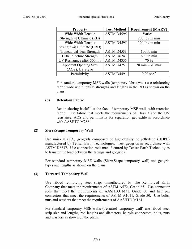
C 202185 (B-2500) Standard Special Provisions Dare County
Property Test Method Requirement (MARV)
Wide Width Tensile Strength @ Ultimate (RD)
ASTM D4595 Varies – 200 lb / in min
Wide Width Tensile Strength @ Ultimate (CRD)
ASTM D4595 100 lb / in min
Trapezoidal Tear Strength ASTM D4533 100 lb min CBR Puncture Strength ASTM D6241 600 lb min
UV Resistance after 500 hrs ASTM D4355 70 % Apparent Opening Size
(AOS), US Sieve ASTM D4751 20 min – 70 max
Permittivity ASTM D4491 0.20 sec-1
For standard temporary MSE walls (temporary fabric wall) use reinforcing fabric wide width tensile strengths and lengths in the RD as shown on the plans.
(b) Retention Fabric
Retain shoring backfill at the face of temporary MSE walls with retention fabric. Use fabric that meets the requirements of Class 3 and the UV resistance, AOS and permittivity for separation geotextile in accordance with AASHTO M288.
(2) SierraScape Temporary Wall
Use uniaxial (UX) geogrids composed of high-density polyethylene (HDPE) manufactured by Tensar Earth Technologies. Test geogrids in accordance with ASTM D6637. Use connection rods manufactured by Tensar Earth Technologies to transfer the load between the facings and geogrids.
For standard temporary MSE walls (SierraScape temporary wall) use geogrid types and lengths as shown on the plans.
(3) Terratrel Temporary Wall
Use ribbed reinforcing steel strips manufactured by The Reinforced Earth Company that meet the requirements of ASTM A572, Grade 65. Use connector rods that meet the requirements of AASHTO M31, Grade 60 and hair pin connectors that meet the requirements of ASTM A1011, Grade 50. Use bolts, nuts and washers that meet the requirements of AASHTO M164. For standard temporary MSE walls (Terratrel temporary wall) use ribbed steel strip size and lengths, rod lengths and diameters, hairpin connectors, bolts, nuts and washers as shown on the plans.
270

C 202185 (B-2500) Standard Special Provisions Dare County
Embedment “Embedment” is defined as the depth of shoring below the bottom of the excavation or the grade in front of the shoring. For cantilever shoring, embedment is the depth of the piling below the grade in front of the shoring. For temporary MSE walls, embedment is the difference between the grade elevation in front of the wall and the elevation of the bottom of the reinforced zone. Portable Concrete Barriers Provide portable concrete barriers in accordance with the plans and if shoring is located within the clear zone as defined in the AASHTO Roadside Design Guide. Use NCDOT portable concrete barriers (PCBs) in accordance with Roadway Standard Drawing No. 1170.01 and Section 1170 of the 2006 Standard Specifications for Roads and Structures. Use Oregon Tall F-Shape Concrete Barriers in accordance with detail drawing and special provision obtained from:
http://www.ncdot.org/doh/preconstruct/wztc/DesRes/English/DesResEng.html The clear distance is defined as the horizontal distance from the back face of the barrier to the edge of pavement and the minimum required clear distance is shown on the traffic control plans. At the Contractor’s option or if the minimum required clear distance is not available, set an unanchored PCB against the traffic side of the shoring and design shoring for traffic impact or use the “surcharge case with traffic impact” for the standard temporary shoring. An anchored PCB or Oregon barrier is required for barriers above and behind temporary MSE walls. Contractor Designed Shoring “Contractor designed shoring” is defined as non-anchored temporary shoring or temporary MSE walls designed by the Contractor. Unless prohibited or required, Contractor designed shoring is optional. Contractor designed shoring is required when notes on plans prohibit the use of standard shoring. Non-anchored Contractor designed shoring is prohibited when notes on plans require the use of temporary MSE walls and Contractor designed temporary MSE walls are prohibited when notes on plans prohibit the use of temporary MSE walls. Before beginning design, survey the shoring location to determine existing elevations and actual design heights. Submit design calculations and drawings including typical sections for review and acceptance showing details of the proposed design and construction sequence in accordance with Article 105-2 of the 2006 Standard Specifications for Roads and Structures. Have shoring designed, detailed and sealed by a Professional Engineer registered in the State of North Carolina. Submit 3 hard copies of design calculations and 10 hard copies of drawings and an electronic copy (pdf or jpeg format on CD or DVD) of both the calculations and drawings. Design non-anchored temporary shoring in accordance with the AASHTO Guide Design Specifications for Bridge Temporary Works and temporary MSE walls in accordance with the AASHTO Allowable Stress Design Standard Specifications for Highway Bridges. Use the following soil parameters for shoring backfill in the reinforced zone.
271

C 202185 (B-2500) Standard Special Provisions Dare County
Total Unit Weight = 120 pcf Friction Angle = 30 degrees Cohesion = 0 psf
Design temporary shoring in accordance with the in-situ assumed soil parameters shown on the plans. Design shoring for a 3-year design service life and a traffic surcharge equal to 240 psf. This surcharge is not applicable for construction traffic. If a construction surcharge will be present within a horizontal distance equal to the height of the shoring, design the shoring for the required construction surcharge. If the edge of pavement or a structure to be protected is within a horizontal distance equal to the height of the shoring, design shoring for a maximum deflection of 3”. Otherwise, design shoring for a maximum deflection of 6”. For non-anchored temporary shoring, the top of shoring elevation is defined as the elevation where the grade intersects the back face of the shoring. For traffic impact, apply 2 kips / ft to the shoring 1.5 ft above the top of shoring elevation. When designing for traffic impact, extend shoring at least 32” above the top of shoring elevation. Otherwise, extend shoring at least 6” above the top of shoring elevation. Standard Shoring Unless notes on plans prohibit the use of one or both types of standard shoring, standard shoring is optional. Submit a “Standard Temporary MSE Wall Selection Form” for each standard temporary MSE wall location and a “Standard Temporary Shoring Selection Form” for up to three standard temporary shoring locations. Submit selection forms at least 14 days before beginning shoring construction. Obtain standard shoring selection forms from:
http://www.ncdot.org/doh/preconstruct/highway/geotech/formdet/standards.html (A) Standard Temporary Shoring
Determine the shoring height, traffic impact, groundwater condition and slope or surcharge case for each standard temporary shoring location. Determine the minimum required extension, embedment and sheet pile section modulus or H pile section from the plans for each location.
(B) Standard Temporary MSE Walls
Choose a standard temporary MSE wall from the multiple temporary MSE wall options shown in the plans. Do not use more than one option per wall location. Step bottom of reinforced zone in increments equal to vertical reinforcement spacing for the wall option chosen. Determine the wall height and slope or surcharge case for each section of standard temporary MSE wall. With the exception of either the first or last section of wall, use horizontal section lengths in increments equal to the following for the wall option chosen.
272

C 202185 (B-2500) Standard Special Provisions Dare County
Standard Temporary MSE Wall
Option Increment
Temporary Fabric Wall 9 ft min (varies) Hilfiker Temporary Wall 10 ft min (varies)
SierraScape Temporary Wall 18 ft – 7 ¼ in Retained Earth Temporary Wall 24 ft
Terratrel Temporary Wall 19 ft – 8 in
Determine the appropriate facings and/or forms and reinforcement length, spacing, strength, type, density and/or size from the plans for each wall section.
Construction Methods When using an anchored PCB, anchor the barrier in accordance with Roadway Standard Drawing 1170.01 and Section 1170 of the 2006 Standard Specifications for Roads and Structures. Control drainage during construction in the vicinity of temporary shoring. Collect and direct run off away from temporary MSE walls, shoring and shoring backfill. (A) Non-anchored Temporary Shoring
Install and interlock sheet piling or install piles as shown on the plans or accepted submittals with a tolerance of 1/2 inch per foot from vertical. Contact the Engineer if the design embedment is not achieved. If piles are placed in drilled holes, perform pile excavation to the required elevations and backfill excavations with concrete and lean sand grout. Remove grout as necessary to install timber lagging. Install timber lagging with a minimum bearing distance of 3” on each pile flange. Backfill voids behind lagging with shoring backfill. Perform welding in accordance with the accepted submittals and Article 1072-20 of the 2006 Standard Specifications for Roads and Structures. (1) Pile Excavation
Excavate a hole with a diameter that will result in at least 3” of clearance around the entire pile. Use equipment of adequate capacity and capable of drilling through soil and non-soil including rock, boulders, debris, man-made objects and any other materials encountered. Blasting is not permitted to advance excavations. Blasting for core removal is permitted only when approved by the Engineer. Dispose of drilling spoils in accordance with Section 802 of the 2006 Standard Specifications for Roads and Structures. Drilling spoils consist of all excavated material including water removed from excavations by either pumping or drilling tools.
273

C 202185 (B-2500) Standard Special Provisions Dare County
If unstable, caving or sloughing soils are encountered, stabilize excavations with clean watertight steel casing. Steel casings may be either sectional type or one continuous corrugated or non-corrugated piece. Provide casings of ample strength to withstand handling and driving stresses and the pressures imposed by concrete, earth or backfill. Use steel casings with an outside diameter equal to the hole size and a minimum wall thickness of 1/4 inch. Before placing concrete, check the water inflow rate in the excavation after any pumps have been removed. If the inflow rate is less than 6” per half hour, remove any water and free fall the concrete into the excavation. Ensure that concrete flows completely around the pile. If the water inflow rate is greater than 6” per half hour, propose and obtain approval of the concrete placement procedure before placing concrete. Center the pile in the excavation and fill the excavation with Class A concrete in accordance with Section 1000 of the 2006 Standard Specifications for Roads and Structures except as modified herein. Provide concrete with a slump of 6 to 8 inches. Use an approved high-range water reducer to achieve this slump. Place concrete in a continuous manner to the bottom of shoring or the elevations shown on the accepted submittals. Fill the remainder of the excavation with a lean sand grout and remove all casings.
(B) Temporary MSE Walls
The Engineer may require a wall preconstruction meeting to discuss the construction and inspection of the temporary MSE walls. If required, conduct the meeting with the Site Superintendent, the Resident or Bridge Maintenance Engineer, the Bridge Construction Engineer and the Geotechnical Operations Engineer before beginning wall construction. Perform all necessary clearing and grubbing in accordance with Section 200 of the 2006 Standard Specifications for Roads and Structures. Excavate as necessary as shown on the plans or accepted submittals. Notify the Engineer when foundation excavation is complete. Do not place shoring backfill or first reinforcement layer until obtaining approval of the excavation depth and foundation material. If applicable, install foundations located within the reinforced zone in accordance with the plans or accepted submittals. Erect and maintain facings and forms as shown on the plans or accepted submittals. Stagger vertical joints of facings and forms to create a running bond when possible unless shown otherwise on the plans or accepted submittals. Place facings and forms as near to vertical as possible with no negative batter. Construct temporary MSE walls with a vertical and horizontal tolerance of 3” when measured with a 10 ft straight edge and an overall vertical plumbness (batter) and horizontal alignment of less than 6”.
274

C 202185 (B-2500) Standard Special Provisions Dare County
Place reinforcement at locations and elevations shown on the plans or accepted submittals and in slight tension free of kinks, folds, wrinkles or creases. Repair or replace any damaged reinforcement. Contact the Engineer when existing or future structures such as foundations, pavements, pipes, inlets or utilities will interfere with reinforcement. To avoid structures, deflect, skew and modify reinforcement. Do not splice reinforcement in the reinforcement direction (RD), i.e., parallel to the wall face. Seams are allowed in the cross-reinforcement direction (CRD). Bond or sew adjacent reinforcing fabric together or overlap fabric a minimum of 18” with seams oriented perpendicular to the wall face. Place shoring backfill in 8 to 10 inch thick lifts and compact in accordance with Subarticle 235-4(C) of the 2006 Standard Specifications for Roads and Structures. Use only hand operated compaction equipment within 3 ft of the wall face. Do not damage reinforcement when placing and compacting shoring backfill. End dumping directly on the reinforcement is not permitted. Do not operate heavy equipment on reinforcement until it is covered with at least 10” of shoring backfill. Do not use sheepsfoot, grid rollers or other types of compaction equipment with feet. Cover reinforcing and retention fabric with at least 3” of shoring backfill. Place top reinforcement layer between 4 and 24 inches below top of wall as shown on the plans or accepted submittals. Bench temporary MSE walls into the sides of excavations where applicable. If the top of wall is within 5 ft of finished grade, remove top form or facing and incorporate the top reinforcement layer into the fill when placing fill in front of the wall. Temporary MSE walls remain in place permanently unless required otherwise.
CHANGEABLE MESSAGE SIGNS (11-21-06) DB11 R 11 Revise the 2006 Standard Specifications for Roads and Structures as follows: Page 11-9, Article 1120-3, Replace the 3rd sentence with the following: Sign operator will adjust flash rate so that no more than two messages will be displayed and be legible to a driver when approaching the sign at the posted speed. FLAGGERS: (2-15-11) DB11 R20 Revise the 2006 Standard Specifications for Roads and Structures as follows: Page 11-13, Article 1150-3 Construction Methods, replace the article with the following:
275
C 202185 (B-2500) Standard Special Provisions Dare County
Provide the service of properly equipped and qualified flaggers (see Roadway Standard Drawing 1150.01) at locations and times for such period as necessary for the control and protection of vehicular and pedestrian traffic. Anyone who controls traffic is required to be qualified. Qualification consists of each flagger receiving proper training in the set-up and techniques of safely and competently performing a flagging operation. Qualification of flaggers is to be done at an NCDOT approved training agency. For a complete listing of these, see the Work Zone Traffic Control’s webpage, http://www.ncdot.gov/doh/preconstruct/wztc/. Prior to beginning work on the project, a Qualification Statement that all flaggers used on the project have been properly trained through an NCDOT approved training resource shall be provided to the Engineer. Flagging operations are not allowed solely for the convenience of the Design-Build Team’s operations. However, if safety issues exist (i.e. sight or stopping sight distance), the Engineer may approve the use of flagging operations. Use flagging methods that comply with the guidelines in the MUTCD. PAVEMENT MARKING LINES (11-21-06) (Rev. 08-17-10) DB12 R01 Revise the 2006 Standard Specifications as follows: Page 12-5, 1205-3 (H) Observation Period, delete 1205-3 (H) and replace with the following: Maintain responsibility for debonding and color of the pavement markings during a 12 month observation period beginning upon final acceptance of the project as defined under Article 105-17. Guarantee the markings under the payment and performance bond in accordance with Article 105-17. During the 12 month observation period, provide pavement marking material that shows no signs of failure due to blistering, chipping, bleeding, discoloration, smearing or spreading under heat or poor adhesion to the pavement materials. Pavement markings that debond due to snowplowing will not be considered a failed marking. Replace, at no additional expense to the Department, any pavement markings that do not perform satisfactorily under traffic during the 12 month observation period. Page 12-8, 1205-4 (C) Application, delete the last two sentences of the second paragraph and replace with the following: Produce in place markings with minimum retroreflective values shown below, as obtained with a LTL 2000 Retroreflectometer or Department approved mobile retroreflectometer. Retroreflective measurements will be taken within 30 days after final placement of the pavement marking. Page 12-9, 1205-4 (D) Observation Period, delete the entire section and replace with the following:
276

C 202185 (B-2500) Standard Special Provisions Dare County
In addition to the requirements of Subarticle 1205-3(H), maintain responsibility for minimum retroreflective values for a 30-day period beginning upon the Engineer’s acceptance of all markings on the project. Guarantee retroreflective values of the markings during the 30-day period under the payment and performance bond in accordance with Article 105-17. Page 12-9, 1205-5 (B) Application, delete the second sentence of the fourth paragraph and replace with the following: Produce in place markings with minimum retroreflective values shown below, as obtained with a LTL 2000 Retroreflectometer or Department approved mobile retroreflectometer. Retroreflective measurements will be taken within 30 days after final placement of the pavement marking. Page 12-10, 1205-5 (C) Observation Period, delete this entire section and replace with the following: Maintain responsibility for minimum retroreflective values for a 30-day period beginning upon satisfactory final placement of all markings on the project. Guarantee retroreflective values of the markings during the 30-day period under the payment and performance bond in accordance with Article 105-17. Page 12-14, Article 1205-9, Maintenance, delete Article 1205-9 and replace with the following: Replace pavement markings that prematurely deteriorate, fail to adhere to the pavement, lack reflectorization, or are otherwise unsatisfactory during the life of the project or during the 12 month observation period as determined by the Engineer at no cost to the Department. Upon notification from the Engineer, winterize the project by placing an initial or additional application of paint pavement marking lines in accordance with Article 1205-8. Payment for Paint Pavement Marking Lines required to winterize the project will be made in accordance with Article 104-8(a). EXCAVATION, TRENCHING, PIPE LAYING & BACKFILLING FOR UTILITIES (02-17-09) DB15 R001 Revise the 2006 Standard Specifications for Roads and Structures as follows: Page 15-5, Article 1505-4 Repair of Pavements, Sidewalks and Driveways, first paragraph, add at the end of the first sentence
in accordance with Section 848.
277

C 202185 (B-2500) Standard Special Provisions Dare County
ON-THE-JOB TRAINING (10-16-07) (Rev. 06-03-09) Z-10 Description The North Carolina Department of Transportation will administer a custom version of the Federal On-the-Job Training (OJT) Program, commonly referred to as the Alternate OJT Program. All contractors (existing and newcomers) will be automatically placed in the Alternate Program. Standard OJT requirements typically associated with individual projects will no longer be applied at the project level. Instead, these requirements will be applicable on an annual basis for each contractor administered by the OJT Program Manager. On the Job Training shall meet the requirements of 23 CFR 230.107 (b), 23 USC – Section 140, this provision and the On-the-Job Training Program Manual. The Alternate OJT Program will allow a contractor to train employees on Federal, State and privately funded projects located in North Carolina. However, priority must be given to training employees on NCDOT Federal-Aid funded projects. Minorities and Women Developing, training and upgrading of minorities and women toward journeymen level status is a primary objective of this special training provision. Accordingly, the Contractor shall make every effort to enroll minority and women as trainees to the extent that such persons are available within a reasonable area of recruitment. This training commitment is not intended, and shall not be used, to discriminate against any applicant for training, whether a member of a minority group or not. Assessing Training Goals The Department through the OJT Program Manager, will assign training goals for a calendar year based on the contractors’ past three years’ activity and the contractors’ anticipated upcoming year’s activity with the Department. At the beginning of each year, all contractors eligible will be contacted by the Department to determine the number of trainees that will be assigned for the upcoming calendar year. At that time, the Contractor shall enter into an agreement with the Department to provide a self-imposed on-the-job training program for the calendar year. This agreement will include a specific number of annual training goals agreed to by both parties. The number of training assignments may range from 1 to 15 per contractor per calendar year. The Contractor shall sign an agreement to fulfill their annual goal for the year. A sample agreement is available at www.ncdot.org/business/ocs/ojt/. Training Classifications The Contractor shall provide on-the-job training aimed at developing full journeyman level workers in the construction craft / operator positions. Preference shall be given to providing training in the following skilled work classifications:
278

C 202185 (B-2500) Standard Special Provisions Dare County
Equipment Operators Office Engineers Truck Drivers Estimators Carpenters Iron / Reinforcing Steel Workers Concrete Finishers Mechanics Pipe Layers Welders
The Department has established common training classifications and their respective training requirements that may be used by the contractors. However, the classifications established are not all-inclusive. Where the training is oriented toward construction applications, training will be allowed in lower-level management positions such as office engineers and estimators. Contractors shall submit new classifications for specific job functions that their employees are performing. The Department will review and recommend for acceptance to FHWA the new classifications proposed by contractors, if applicable. New classifications shall meet the following requirements:
Proposed training classifications are reasonable and realistic based on the job skill classification needs, and
The number of training hours specified in the training classification is consistent with common practices and provides enough time for the trainee to obtain journeyman level status.
The Contractor may allow trainees to be trained by a subcontractor provided that the Contractor retains primary responsibility for meeting the training and this provision is made applicable to the subcontract. However, only the Contractor will receive credit towards the annual goal for the trainee. Where feasible, 25 percent of apprentices or trainees in each occupation shall be in their first year of apprenticeship or training. The number of trainees shall be distributed among the work classifications on the basis of the contractor’s needs and the availability of journeymen in the various classifications within a reasonable area of recruitment. No employee shall be employed as a trainee in any classification in which they have successfully completed a training course leading to journeyman level status or in which they have been employed as a journeyman. Records and Reports The Contractor shall maintain enrollment, monthly and completion reports documenting company compliance under these contract documents. These documents and any other information, as requested, shall be submitted to the OJT Program Manager. Upon completion and graduation of the program, the Contractor shall provide each trainee with a certification Certificate showing the type and length of training satisfactorily completed.
279

C 202185 (B-2500) Standard Special Provisions Dare County
Trainee Interviews All trainees enrolled in the program shall receive an initial and Trainee / Post graduate interview conducted by the OJT program staff. Trainee Wages Contractors shall compensate trainees on a graduating pay scale based upon a percentage of the prevailing minimum journeyman wages (Davis-Bacon Act). Minimum pay shall be as follows:
60 percent of the journeyman wage for the first half of the training period 75 percent of the journeyman wage for the third quarter of the training period 90 percent of the journeyman wage for the last quarter of the training period
In no instance shall a trainee be paid less than the local minimum wage. The Contractor shall adhere to the minimum hourly wage rate that will satisfy both the NCDOL and the Department. Achieving or Failing to Meet Training Goals The Contractor will be credited for each trainee employed by him on the contract work who is currently enrolled or becomes enrolled in an approved program and who receives training for at least 50 percent of the specific program requirement. Trainees will be allowed to be transferred between projects if required by the Contractor’s scheduled workload to meet training goals. If a contractor fails to attain their training assignments for the calendar year, they may be taken off the NCDOT’s Bidders List. Measurement and Payment No compensation will be made for providing required training in accordance with these contract documents.
280

C 202185 (B-2500) Availability of Funds – Termination of Contracts Dare County
STANDARD SPECIAL PROVISION
AVAILABILITY OF FUNDS – TERMINATION OF CONTRACTS (05-20-08) (Rev. 09-28-10) Z-2 General Statute 143C-6-11. (h) Highway Appropriation is hereby incorporated verbatim in this contract as follows: “(h) Amounts Encumbered – Transportation project appropriations may be encumbered in the amount of allotments made to the Department of Transportation by the Director for the estimated payments for transportation project contract work to be performed in the appropriation fiscal year. The allotments shall be multiyear allotments and shall be based on estimated revenues and shall be subject to the maximum contract authority contained in General Statute 143C-6-11(c). Payment for transportation project work performed pursuant to contract in any fiscal year other than the current fiscal year is subject to appropriations by the General Assembly. Transportation project contracts shall contain a schedule of estimated completion progress, and any acceleration of this progress shall be subject to the approval of the Department of Transportation provided funds are available. The State reserves the right to terminate or suspend any transportation project contract, and any transportation project contract shall be so terminated or suspended if funds will not be available for payment of the work to be performed during that fiscal year pursuant to the contract. In the event of termination of any contract, the contractor shall be given a written notice of termination at least 60 days before completion of scheduled work for which funds are available. In the event of termination, the contractor shall be paid for the work already performed in accordance with the contract specifications.” Payment will be made on any contract terminated pursuant to the special provision in accordance with Article 108-13(E), of the North Carolina Department of Transportation Standard Specifications for Roads and Structures, dated July 1, 2006 and as amended by the Standard Special Provision, Division One found elsewhere in this RFP.
281

C 202185 (B-2500) NCDOT General Seed Specifications for Seed Quality Dare County
*** STANDARD SPECIAL PROVISIONS ***
NCDOT GENERAL SEED SPECIFICATIONS FOR SEED QUALITY
(11-18-08) Z-3 Seed shall be sampled and tested by the North Carolina Department of Agriculture and Consumer Services, Seed Testing Laboratory. When said samples are collected, the vendor shall supply an independent laboratory report for each lot to be tested. Results from seed so sampled shall be final. Seed not meeting the specifications shall be rejected by the Department of Transportation and shall not be delivered to North Carolina Department of Transportation warehouses. If seed has been delivered it shall be available for pickup and replacement at the supplier's expense. Any re-labeling required by the North Carolina Department of Agriculture and Consumer Services, Seed Testing Laboratory, that would cause the label to reflect as otherwise specified herein shall be rejected by the North Carolina Department of Transportation. Seed shall be free from seeds of the noxious weeds Johnsongrass, Balloonvine, Jimsonweed, Witchweed, Itchgrass, Serrated Tussock, Showy Crotalaria, Smooth Crotalaria, Sicklepod, Sandbur, Wild Onion, and Wild Garlic. Seed shall not be labeled with the above weed species on the seed analysis label. Tolerances as applied by the Association of Official Seed Analysts will NOT be allowed for the above noxious weeds except for Wild Onion and Wild Garlic. Tolerances established by the Association of Official Seed Analysts will generally be recognized. However, for the purpose of figuring pure live seed, the found pure seed and found germination percentages as reported by the North Carolina Department of Agriculture and Consumer Services, Seed Testing Laboratory will be used. Allowances, as established by the NCDOT, will be recognized for minimum pure live seed as listed on the following pages. The specifications for restricted noxious weed seed refers to the number per pound as follows:
Restricted Noxious Weed
Limitations per Lb. of Seed
Restricted Noxious Weed
Limitations per Lb. of Seed
Blessed Thistle 4 seeds Cornflower (Ragged Robin) 27 seeds Cocklebur 4 seeds Texas Panicum 27 seeds
Spurred Anoda 4 seeds Bracted Plantain 54 seeds Velvetleaf 4 seeds Buckhorn Plantain 54 seeds
Morning-glory 8 seeds Broadleaf Dock 54 seeds Corn Cockle 10 seeds Curly Dock 54 seeds Wild Radish 12 seeds Dodder 54 seeds
Purple Nutsedge 27 seeds Giant Foxtail 54 seeds Yellow Nutsedge 27 seeds Horsenettle 54 seeds Canada Thistle 27 seeds Quackgrass 54 seeds Field Bindweed 27 seeds Wild Mustard 54 seeds
Hedge Bindweed 27 seeds
282

C 202185 (B-2500) NCDOT General Seed Specifications for Seed Quality Dare County Seed of Pensacola Bahiagrass shall not contain more than 7% inert matter, Kentucky Bluegrass, Centipede and Fine or Hard Fescue shall not contain more than 5% inert matter whereas a maximum of 2% inert matter will be allowed on all other kinds of seed. In addition, all seed shall not contain more than 2% other crop seed nor more than 1% total weed seed. The germination rate as tested by the North Carolina Department of Agriculture shall not fall below 70%, which includes both dormant and hard seed. Seed shall be labeled with not more than 7%, 5% or 2% inert matter (according to above specifications), 2% other crop seed and 1% total weed seed. Exceptions may be made for minimum pure live seed allowances when cases of seed variety shortages are verified. Pure live seed percentages will be applied in a verified shortage situation. Those purchase orders of deficient seed lots will be credited with the percentage that the seed is deficient. FURTHER SPECIFICATIONS FOR EACH SEED GROUP ARE GIVEN BELOW: Minimum 85% pure live seed; maximum 1% total weed seed; maximum 2% total other crop seed; maximum 144 restricted noxious weed seed per pound. Seed less than 83% pure live seed will not be approved. Sericea Lespedeza Oats (seeds) Minimum 80% pure live seed; maximum 1% total weed seed; maximum 2% total other crop; maximum 144 restricted noxious weed seed per pound. Seed less than 78% pure live seed will not be approved.
Tall Fescue (all approved varieties) Bermudagrass Kobe Lespedeza Browntop Millet Korean Lespedeza German Millet - Strain R Weeping Lovegrass Clover - Red/White/Crimson Carpetgrass
Minimum 78% pure live seed; maximum 1% total weed seed; maximum 2% total other crop seed; maximum 144 restricted noxious weed seed per pound. Seed less than 76% pure live seed will not be approved. Common or Sweet Sundangrass Minimum 76% pure live seed; maximum 1% total weed seed; maximum 2% total other crop seed; maximum 144 restricted noxious weed seed per pound. Seed less than 74% pure live seed will not be approved. Rye (grain; all varieties) Kentucky Bluegrass (all approved varieties) Hard Fescue (all approved varieties) Shrub (bicolor) Lespedeza
283

C 202185 (B-2500) NCDOT General Seed Specifications for Seed Quality Dare County Minimum 70% pure live seed; maximum 1% total weed seed; maximum 2% total other crop seed; maximum 144 restricted noxious weed seed per pound. Seed less than 70% pure live seed will not be approved.
Centipedegrass Japanese Millet Crownvetch Reed Canary Grass Pensacola Bahiagrass Zoysia
Minimum 70% pure live seed; maximum 1% total weed seed; maximum 2% total other crop seed; maximum 5% inert matter; maximum 144 restricted noxious weed seed per pound. Barnyard Grass Big Bluestem Little Bluestem Bristly Locust Birdsfoot Trefoil Indiangrass Orchardgrass Switchgrass Yellow Blossom Sweet Clover
284
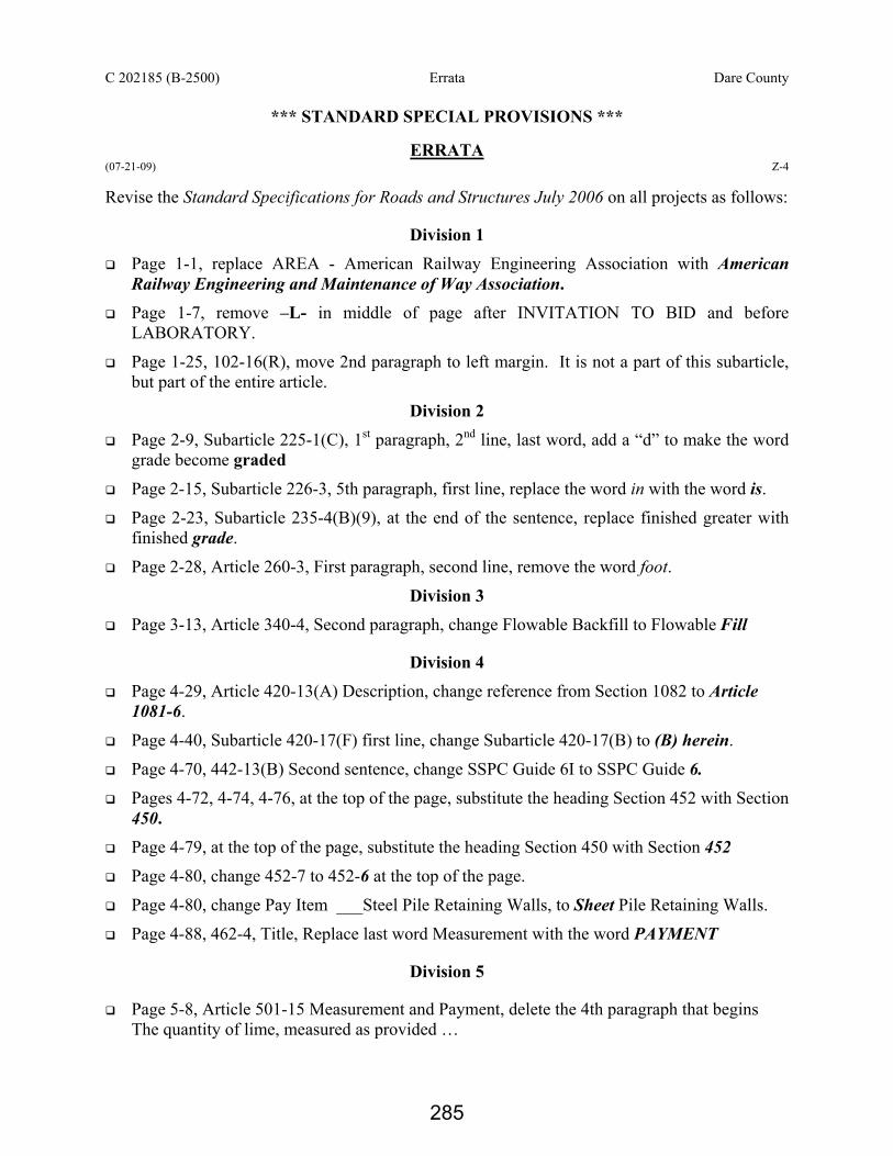
C 202185 (B-2500) Errata Dare County
*** STANDARD SPECIAL PROVISIONS ***
ERRATA (07-21-09) Z-4 Revise the Standard Specifications for Roads and Structures July 2006 on all projects as follows:
Division 1 Page 1-1, replace AREA - American Railway Engineering Association with American
Railway Engineering and Maintenance of Way Association. Page 1-7, remove –L- in middle of page after INVITATION TO BID and before
LABORATORY.
Page 1-25, 102-16(R), move 2nd paragraph to left margin. It is not a part of this subarticle, but part of the entire article.
Division 2
Page 2-9, Subarticle 225-1(C), 1st paragraph, 2nd line, last word, add a “d” to make the word grade become graded
Page 2-15, Subarticle 226-3, 5th paragraph, first line, replace the word in with the word is.
Page 2-23, Subarticle 235-4(B)(9), at the end of the sentence, replace finished greater with finished grade.
Page 2-28, Article 260-3, First paragraph, second line, remove the word foot.
Division 3 Page 3-13, Article 340-4, Second paragraph, change Flowable Backfill to Flowable Fill
Division 4 Page 4-29, Article 420-13(A) Description, change reference from Section 1082 to Article
1081-6.
Page 4-40, Subarticle 420-17(F) first line, change Subarticle 420-17(B) to (B) herein.
Page 4-70, 442-13(B) Second sentence, change SSPC Guide 6I to SSPC Guide 6.
Pages 4-72, 4-74, 4-76, at the top of the page, substitute the heading Section 452 with Section 450.
Page 4-79, at the top of the page, substitute the heading Section 450 with Section 452
Page 4-80, change 452-7 to 452-6 at the top of the page.
Page 4-80, change Pay Item ___Steel Pile Retaining Walls, to Sheet Pile Retaining Walls.
Page 4-88, 462-4, Title, Replace last word Measurement with the word PAYMENT
Division 5
Page 5-8, Article 501-15 Measurement and Payment, delete the 4th paragraph that begins The quantity of lime, measured as provided …
285

C 202185 (B-2500) Errata Dare County
Page 5-14, Article 520-11 Measurement and Payment, first paragraph, second line, delete
will be.
Division 6
Page 6-3, Article 600-9, 2nd Paragraph on this page, replace 818-5 with 818-4.
Pages 6-30 and 31, Subarticle 610-3(A)(13) Move 2 paragraphs from the margin to the right under the number (13).
Page 6-43, Article 610-8, 4th paragraph, remove the first the
Page 6-44, 2nd full paragraph, 1st sentence, delete the first and and add transverse just before cross-slope control.
Page 6-51, at the top of the page, add 610-14 on the same line, and just before the heading MAINTENANCE.
Page 6-53, Article 620-4 sixth paragraph, second line; the word that should be which.
Page 6-66, title, Replace EXISTNG with EXISTING
Page 6-66, Article 657-1, Description, first sentence, replace PS/AR (hot-poured rubber asphalt with hot applied joint sealer.
Page 6-66, Article 657-2, replace PS/AR (Hot-Poured Rubber Asphalt with the following:
Item Section
Hot Applied Joint Sealer 1028-2
Page 6-67, at the top of the page, substitute the heading Section 654 with Section 657.
Page 6-67, Article 657-3 Construction Methods, 2nd paragraph, replace PS/AR sealant with hot applied joint sealer.
Page 6-71, 660-9(B)(1), Replace the first sentence of the first paragraph with the following: Using the quantities shown in Table 660-1, apply asphalt material to the existing surface followed by an application of No. 78 M or lightweight aggregate.
Page 6-89, Add a period at the end of the last sentence at the bottom of the page.
Page 6-90, Article 663-5, first paragraph, first sentence, change 50oF to 50oF; third paragraph, fourth sentence change 325oF to 325oF.
Division 7 Page 7-12, at the top of the page, substitute the heading Section 710 with Section 700.
Page 7-15, Article 710-9, 4th paragraph, last line, change 710-11(B) to 710-10(B).
286

C 202185 (B-2500) Errata Dare County
Division 8
Page 8-13, Article 808-3, 4th Paragraph, third line, replace the word Eexcavation with the word Excavation
Page 8-35, Article 848-2, Item: Replace Cncrete with Concrete
Division 9 Page 9-2, add 901-3 just before CONSTRUCTION METHODS
Division 10
Page 10-12, near bottom of page add (C) before Proportioning and Mixing of Modified Compositions, which should be bold type.
Page 10-28, at the top of the page, substitute Section 1006 for 1005.
Page 10-54, Subarticle 1018-2A), First line, substitute (B) for II, third line, substitute (B)(2) for II-b.
Pages 10-56, 10-58, 10-60 at the top of the page, substitute Section 1018 with Section 1020.
Page 10-84, Table 1042-1, Class 2, Maximum, change from 23r to 23.
Page 10-84, Article 1042-2 Testing, last sentence, replace the word alterations with the word cycles.
Page 10-100, Table 1056-1, replace on the line for Trapezoidal Tear Strength:
Type 1 Type 2 Type 3 Type 4
Class A Class B Soil Stabilization
45 lb 75 lb -- -- 75 lb
Page 10-116, Subarticle 1070-10, first paragraph, second sentence, add or just before cold-forged sleeve.
Pages 10-136 through 10-147, at the top of the page, substitute Section 1074 with Section 1072.
Page 10-157, Article 1077-11, first paragraph, change the reference from Subarticle 420-18(B) to Subarticle 420-17(B).
Page 10-200, Subarticle 1080-14(B), change reference to ASTM D3359
Page 10-211, at the top of the page, substitute Section 1081 with Section 1082.
Page 10-229, add 1088-6 BLANK on the line above 1088-7 TUBULAR MARKERS.
Page 10-244, add 1089-10 BLANK and 1089-11 BLANK on the lines just above 1089-12 FLAGGER.
Page 10-272, delete Article 1098-6 in its entirety. Renumber Articles 1098-7 through 1098-17 as Articles 1098-6 through 1098-16 consecutively.
287

C 202185 (B-2500) Errata Dare County
Division 12
Page 12-21 Add 1266-2 just before the heading MATERIALS.
Division 14 Page 14-33, Article 1413-6, first paragraph, first sentence, first line, replace the word made
with the words paid for.
Division 15
Page 15-2 add 1500-4 just before the heading WEEKEND, NIGHT AND HOLIDAY WORK.
Page 15-4, Subarticle 1505-3(A)(2), replace the 2nd line with the following: Provide shielding or shoring as required under Section 150 or as required elsewhere in the contract.
Page 15-5, add 1505-6 on the same line and just before the heading MEASUREMENT AND PAYMENT. (Remove the period after PAYMENT.)
Page 15-6, Article 1505-6(3), delete in Section 1175 and replace it with elsewhere in the contract.
Page 15-8, add 1510-4 on the same line and just before the heading MEASUREMENT AND PAYMENT.
Page 15-10, substitute BLANK for CONSTRUCTION REQUIREMENTS on the same line and just before 1515-4.
Page 15-10, substitute CONSTRUCTION REQUIREMENTS for General Requirements
Page 15-10, Article 1515-4, add (D) just before the bolded Fire Hydrants.
Page 15-13, Article 1520-3, 8th paragraph, add pipe after diameter.
Page 15-22, add 1540-3 on the same line and just before the heading CONSTRUCTION REQUIREMENTS
Page 15-28, Replace 1550-6 METHOD OF MEASUREMENT with MEASUREMENT AND PAYMENT.
Division 16 Page 16-12, Subarticle 1632-1(C) ¼ Inch hardware cloth, change the minimum width from
24 inches to 48 inches.
Division 17
Page 17-19, Subarticle 1725-2 Material, Second paragraph, change Article 1098-7 to 1098-8
Page 17-20, Subarticle 1726-2 Material, Second paragraph, change Article 1098-8 to 1098-9
END
288

C 202185 (B-2500) Award of Contract Dare County
*** STANDARD SPECIAL PROVISIONS ***
AWARD OF CONTRACT (6-28-77) Z-6 “The North Carolina Department of Transportation, in accordance with the provisions of Title VI of the Civil Rights Act of 1964 (78 Stat. 252) and the Regulations of the Department of Transportation (49 C.F.R., Part 21), issued pursuant to such act, hereby notifies all bidders that it will affirmatively insure that the contract entered into pursuant to this advertisement will be awarded to the lowest responsible bidder without discrimination on the ground of race, color, or national origin”.
289

C 202185 (B-2500) Minority and Female Employment Requirements Dare County
*** STANDARD SPECIAL PROVISIONS ***
MINORITY AND FEMALE EMPLOYMENT REQUIREMENTS (12-18-07) Z-7
NOTICE OF REQUIREMENTS FOR AFFIRMATIVE ACTION TO ENSURE EQUAL EMPLOYMENT OPPORTUNITY (EXECUTIVE NUMBER 11246) 1. The goals and timetables for minority and female participation, expressed in percentage terms for the Contractor’s aggregate workforce in each trade on all construction work in the covered area, see as shown on the attached sheet entitled “Employment Goals for Minority and Female Participation”. These goals are applicable to all the Contractor’s construction work (whether or not it is Federal or federally assisted) performed in the covered area. If the Contractor performs construction work in a geographical area located outside of the covered area, it shall apply the goals established for such geographical area where the work is actually performed. With regard to this second area, the Contractor also is subject to the goals for both its federally involved and nonfederally involved construction. The Contractor’s compliance with the Executive Order and the regulations in 41 CFR Part 60-4 shall be based on its implementation of the Equal Opportunity Clause, specific affirmative action obligations required by the specifications set forth in 41 CFR 60-4.3(a), and its effort to meet the goals. The hours of minority and female employment and training must be substantially uniform throughout the length of the contract, and in each trade and the Contractor shall make a good faith effort to employ minorities and women evenly on each of its projects. The transfer of minority or female employees or trainees from Contractor to Contractor or from project to project or the sole purpose of meeting the Contractor’s goals shall be a violation of the contract, the executive Order and the regulations in 41 CFR Part 60-4. Compliance with the goals will be measured against the total work hours performed. 2. As used in this Notice and in the contract resulting from this solicitation, the “covered area” is the county or counties shown on the cover sheet of the proposal form and contract.
290

C 202185 (B-2500) Minority and Female Employment Requirements Dare County
EMPLOYMENT GOALS FOR MINORITY AND FEMALE PARTICIPATION
Economic Areas
Area 023 29.7% Area 026 33.5% Area 029 15.7%
Bertie County Bladen County Alexander County Camden County Hoke County Anson County Chowan County Richmond County Burke County Gates County Robeson County Cabarrus County Hertford County Sampson County Caldwell County Pasquotank County Scotland County Catawba County Perquimans County Cleveland County Area 027 24.7% Iredell County Area 024 31.7% Chatham County Lincoln County Beaufort County Franklin County Polk County Carteret County Granville County Rowan County Craven County Harnett County Rutherford County Dare County Johnston County Stanly County Edgecombe County Lee County Green County Person County Area 0480 8.5%
Halifax County Vance County Buncombe County Hyde County Warren County Madison County Jones County Lenoir County Area 028 15.5% Area 030 6.3%
Martin County Alleghany County Avery County Nash County Ashe County Cherokee County Northampton County Caswell County Clay County Pamlico County Davie County Graham County Pitt County Montgomery County Haywood County Tyrrell County Moore County Henderson County Washington County Rockingham County Jackson County Wayne County Surry County McDowell County Wilson County Watauga County Macon County Wilkes County Mitchell County Area 025 23.5% Swain County Columbus County Transylvania County Duplin County Yancey County Onslow County Pender County ______________________________________________________________________________
291

C 202185 (B-2500) Minority and Female Employment Requirements Dare County
SMSA Areas
Area 5720 26.6% Area 6640 22.8% Area 3120 16.4%
Currituck County Durham County Davidson County Orange County Forsyth County Area 9200 20.7% Wake County Guilford County Brunswick County Randolph County New Hanover County Area 1300 16.2% Stokes County Alamance County Yadkin County Area 2560 24.2% Cumberland County Area 1520 18.3%
Gaston County Mecklenburg County Union County ______________________________________________________________________________
Goals for Female
Participation in Each Trade
(Statewide) 6.9%
292

C 202185 (B-2500) Required Contract Provisions Federal-Aid Construction Contracts Dare County
*** STANDARD SPECIAL PROVISIONS *** REQUIRED CONTRACT PROVISIONS FEDERAL-AID CONSTRUCTION CONTRACTS (FHWA-1273)
I. General
II. Nondiscrimination
III. Nonsegregated Facilities
IV. Payment of Predetermined Minimum Wage
V. Statements and Payrolls
VI. Record of Materials, Supplies, and Labor
VII. Subletting or Assigning the Contract
VIII. Safety: Accident Prevention
IX. False Statements Concerning Highway Projects
X. Implementation of Clean Air Act and Federal Water Pollution Control Act
XI. Certification Regarding Debarment, Suspension Ineligibility, and Voluntary Exclusion
XII. Certification Regarding Use of Contract Funds for Lobbying
I. GENERAL 1. These contract provisions shall apply to all work performed on the contract by the contractor's own organization and with the
assistance of workers under the contractor's immediate superintendence and to all work performed on the contract by piecework, station work, or by subcontract.
2. Except as otherwise provided for in each section, the contractor shall insert in each subcontract all of the stipulations contained in these Required Contract Provisions, and further require their inclusion in any lower tier subcontract or purchase order that may in turn be made. The Required Contract Provisions shall not be incorporated by reference in any case. The prime contractor shall be responsible for compliance by any subcontractor or lower tier subcontractor with these Required Contract Provisions.
3. A breach of any of the stipulations contained in these Required Contract Provisions shall be sufficient grounds for termination of the contract.
4. A breach of the following clauses of the Required Contract Provisions may also be grounds for debarment as provided in 29 CFR 5.12:
Section I, paragraph 2;
Section IV, paragraphs 1, 2, 3, 4, and 7;
Section V, paragraphs 1 and 2a through 2g.
5. Disputes arising out of the labor standards provisions of Section IV (except paragraph 5) and Section V of these Required Contract Provisions shall not be subject to the general disputes clause of this contract. Such disputes shall be resolved in accordance with the procedures of the U.S. Department of Labor (DOL) as set forth in 29 CFR 5, 6, and 7. Disputes within the meaning of this clause include disputes between the contractor (or any of its subcontractors) and the contracting agency, the DOL, or the contractor's employees or their representatives.
6. Selection of Labor: During the performance of this contract, the contractor shall not:
a. discriminate against labor from any other State, possession, or territory of the United States (except for employment preference for Appalachian contracts, when applicable, as specified in Attachment A), or
b. employ convict labor for any purpose within the limits of the project unless it is labor performed by convicts who are on parole, supervised release, or probation.
II. NONDISCRIMINATION (Applicable to all Federal-aid construction contracts and to all related subcontracts of $10,000 or more.)
1. Equal Employment Opportunity: Equal employment opportunity (EEO) requirements not to discriminate and to take affirmative action to assure equal opportunity as set forth under laws, executive orders, rules, regulations (28 CFR 35, 29 CFR 1630 and 41 CFR 60) and orders of the Secretary of Labor as modified by the provisions prescribed herein, and imposed pursuant to 23 U.S.C. 140 shall constitute the EEO and specific affirmative action standards for the contractor's project activities under this contract. The Equal Opportunity Construction Contract Specifications set forth under 41 CFR 60-4.3 and the provisions of the American Disabilities Act of 1990 (42 U.S.C. 12101 et seq.) set forth under 28 CFR 35 and 29 CFR 1630 are incorporated by reference in this contract. In the execution of this contract, the contractor agrees to comply with the following minimum specific requirement activities of EEO:
a. The contractor will work with the State highway agency (SHA) and the Federal Government in carrying out EEO obligations and in their review of his/her activities under the contract.
293

C 202185 (B-2500) Required Contract Provisions Federal-Aid Construction Contracts Dare County
b. The contractor will accept as his operating policy the following statement:
"It is the policy of this Company to assure that applicants are employed, and that employees are treated during employment, without regard to their race, religion, sex, color, national origin, age or disability. Such action shall include: employment, upgrading, demotion, or transfer; recruitment or recruitment advertising; layoff or termination; rates of pay or other forms of compensation; and selection for training, including apprenticeship, preapprenticeship, and/or on-the-job training."
2. EEO Officer: The contractor will designate and make known to the SHA contracting officers an EEO Officer who will have the responsibility for and must be capable of effectively administering and promoting an active contractor program of EEO and who must be assigned adequate authority and responsibility to do so.
3. Dissemination of Policy: All members of the contractor's staff who are authorized to hire, supervise, promote, and discharge employees, or who recommend such action, or who are substantially involved in such action, will be made fully cognizant of, and will implement, the contractor's EEO policy and contractual responsibilities to provide EEO in each grade and classification of employment. To ensure that the above agreement will be met, the following actions will be taken as a minimum:
a. Periodic meetings of supervisory and personnel office employees will be conducted before the start of work and then not less often than once every six months, at which time the contractor's EEO policy and its implementation will be reviewed and explained. The meetings will be conducted by the EEO Officer.
b. All new supervisory or personnel office employees will be given a thorough indoctrination by the EEO Officer, covering all major aspects of the contractor's EEO obligations within thirty days following their reporting for duty with the contractor.
c. All personnel who are engaged in direct recruitment for the project will be instructed by the EEO Officer in the contractor's procedures for locating and hiring minority group employees.
d. Notices and posters setting forth the contractor's EEO policy will be placed in areas readily accessible to employees, applicants for employment and potential employees.
e. The contractor's EEO policy and the procedures to implement such policy will be brought to the attention of employees by means of meetings, employee handbooks, or other appropriate means.
4. Recruitment: When advertising for employees, the contractor will include in all advertisements for employees the notation: "An Equal Opportunity Employer." All such advertisements will be placed in publications having a large circulation among minority groups in the area from which the project work force would normally be derived.
a. The contractor will, unless precluded by a valid bargaining agreement, conduct systematic and direct recruitment through public and private employee referral sources likely to yield qualified minority group applicants. To meet this requirement, the contractor will identify sources of potential minority group employees, and establish with such identified sources procedures whereby minority group applicants may be referred to the contractor for employment consideration.
b. In the event the contractor has a valid bargaining agreement providing for exclusive hiring hall referrals, he is expected to observe the provisions of that agreement to the extent that the system permits the contractor's compliance with EEO contract provisions. (The DOL has held that where implementation of such agreements have the effect of discriminating against minorities or women, or obligates the contractor to do the same, such implementation violates Executive Order 11246, as amended.)
c. The contractor will encourage his present employees to refer minority group applicants for employment. Information and procedures with regard to referring minority group applicants will be discussed with employees.
5. Personnel Actions: Wages, working conditions, and employee benefits shall be established and administered, and personnel actions of every type, including hiring, upgrading, promotion, transfer, demotion, layoff, and termination, shall be taken without regard to race, color, religion, sex, national origin, age or disability. The following procedures shall be followed:
a. The contractor will conduct periodic inspections of project sites to insure that working conditions and employee facilities do not indicate discriminatory treatment of project site personnel.
b. The contractor will periodically evaluate the spread of wages paid within each classification to determine any evidence of discriminatory wage practices.
c. The contractor will periodically review selected personnel actions in depth to determine whether there is evidence of discrimination. Where evidence is found, the contractor will promptly take corrective action. If the review indicates that the discrimination may extend beyond the actions reviewed, such corrective action shall include all affected persons.
d. The contractor will promptly investigate all complaints of alleged discrimination made to the contractor in connection with his obligations under this contract, will attempt to resolve such complaints, and will take appropriate corrective action within a reasonable time. If the investigation indicates that the discrimination may affect persons other than the complainant, such corrective action shall include such other persons. Upon completion of each investigation, the contractor will inform every complainant of all of his avenues of appeal.
6. Training and Promotion: a. The contractor will assist in locating, qualifying, and increasing the skills of minority group and women employees, and
applicants for employment.
b. Consistent with the contractor's work force requirements and as permissible under Federal and State regulations, the contractor shall make full use of training programs, i.e., apprenticeship, and on-the-job training programs for the geographical area of contract performance. Where feasible, 25 percent of apprentices or trainees in each occupation shall be in their first year of apprenticeship or training. In the event a special provision for training is provided under this contract, this subparagraph will be superseded as indicated in the special provision.
294

C 202185 (B-2500) Required Contract Provisions Federal-Aid Construction Contracts Dare County
c. The contractor will advise employees and applicants for employment of available training programs and entrance requirements for each.
d. The contractor will periodically review the training and promotion potential of minority group and women employees and will encourage eligible employees to apply for such training and promotion.
7. Unions: If the contractor relies in whole or in part upon unions as a source of employees, the contractor will use his/her best efforts to obtain the cooperation of such unions to increase opportunities for minority groups and women within the unions, and to effect referrals by such unions of minority and female employees. Actions by the contractor either directly or through a contractor's association acting as agent will include the procedures set forth below:
a. The contractor will use best efforts to develop, in cooperation with the unions, joint training programs aimed toward qualifying more minority group members and women for membership in the unions and increasing the skills of minority group employees and women so that they may qualify for higher paying employment.
b. The contractor will use best efforts to incorporate an EEO clause into each union agreement to the end that such union will be contractually bound to refer applicants without regard to their race, color, religion, sex, national origin, age or disability.
c. The contractor is to obtain information as to the referral practices and policies of the labor union except that to the extent such information is within the exclusive possession of the labor union and such labor union refuses to furnish such information to the contractor, the contractor shall so certify to the SHA and shall set forth what efforts have been made to obtain such information.
d. In the event the union is unable to provide the contractor with a reasonable flow of minority and women referrals within the time limit set forth in the collective bargaining agreement, the contractor will, through independent recruitment efforts, fill the employment vacancies without regard to race, color, religion, sex, national origin, age or disability; making full efforts to obtain qualified and/or qualifiable minority group persons and women. (The DOL has held that it shall be no excuse that the union with which the contractor has a collective bargaining agreement providing for exclusive referral failed to refer minority employees.) In the event the union referral practice prevents the contractor from meeting the obligations pursuant to Executive Order 11246, as amended, and these special provisions, such contractor shall immediately notify the SHA.
8. Selection of Subcontractors, Procurement of Materials and Leasing of Equipment: The contractor shall not discriminate on the grounds of race, color, religion, sex, national origin, age or disability in the selection and retention of subcontractors, including procurement of materials and leases of equipment.
a. The contractor shall notify all potential subcontractors and suppliers of his/her EEO obligations under this contract.
b. Disadvantaged business enterprises (DBE), as defined in 49 CFR 23, shall have equal opportunity to compete for and perform subcontracts which the contractor enters into pursuant to this contract. The contractor will use his best efforts to solicit bids from and to utilize DBE subcontractors or subcontractors with meaningful minority group and female representation among their employees. Contractors shall obtain lists of DBE construction firms from SHA personnel.
c. The contractor will use his best efforts to ensure subcontractor compliance with their EEO obligations.
9. Records and Reports: The contractor shall keep such records as necessary to document compliance with the EEO requirements. Such records shall be retained for a period of three years following completion of the contract work and shall be available at reasonable times and places for inspection by authorized representatives of the SHA and the FHWA.
a. The records kept by the contractor shall document the following:
1. The number of minority and non-minority group members and women employed in each work classification on the project;
2. The progress and efforts being made in cooperation with unions, when applicable, to increase employment opportunities for minorities and women;
3. The progress and efforts being made in locating, hiring, training, qualifying, and upgrading minority and female employees; and
4. The progress and efforts being made in securing the services of DBE subcontractors or subcontractors with meaningful minority and female representation among their employees.
b. The contractors will submit an annual report to the SHA each July for the duration of the project, indicating the number of minority, women, and non-minority group employees currently engaged in each work classification required by the contract work. This information is to be reported on Form FHWA-1391. If on-the-job training is being required by special provision, the contractor will be required to collect and report training data.
III. NONSEGREGATED FACILITIES (Applicable to all Federal-aid construction contracts and to all related subcontracts of $10,000 or more.)
a. By submission of this bid, the execution of this contract or subcontract, or the consummation of this material supply agreement or purchase order, as appropriate, the bidder, Federal-aid construction contractor, subcontractor, material supplier, or vendor, as appropriate, certifies that the firm does not maintain or provide for its employees any segregated facilities at any of its establishments, and that the firm does not permit its employees to perform their services at any location, under its control, where segregated facilities are maintained. The firm agrees that a breach of this certification is a violation of the EEO provisions of this contract. The firm further certifies that no employee will be denied access to adequate facilities on the basis of sex or disability.
b. As used in this certification, the term "segregated facilities" means any waiting rooms, work areas, restrooms and washrooms, restaurants and other eating areas, timeclocks, locker rooms, and other storage or dressing areas, parking lots, drinking fountains, recreation or entertainment areas, transportation, and housing facilities provided for employees which are segregated by explicit directive, or are, in fact, segregated on the basis of race, color, religion, national origin, age or disability, because of habit, local custom, or otherwise. The only exception will be for the disabled when the demands for accessibility override (e.g. disabled parking).
295

C 202185 (B-2500) Required Contract Provisions Federal-Aid Construction Contracts Dare County
c. The contractor agrees that it has obtained or will obtain identical certification from proposed subcontractors or material suppliers prior to award of subcontracts or consummation of material supply agreements of $10,000 or more and that it will retain such certifications in its files.
IV. PAYMENT OF PREDETERMINED MINIMUM WAGE (Applicable to all Federal-aid construction contracts exceeding $2,000 and to all related subcontracts, except for projects located on roadways classified as local roads or rural minor collectors, which are exempt.)
1. General: a. All mechanics and laborers employed or working upon the site of the work will be paid unconditionally and not less often than
once a week and without subsequent deduction or rebate on any account [except such payroll deductions as are permitted by regulations (29 CFR 3) issued by the Secretary of Labor under the Copeland Act (40 U.S.C. 276c)] the full amounts of wages and bona fide fringe benefits (or cash equivalents thereof) due at time of payment. The payment shall be computed at wage rates not less than those contained in the wage determination of the Secretary of Labor (hereinafter "the wage determination") which is attached hereto and made a part hereof, regardless of any contractual relationship which may be alleged to exist between the contractor or its subcontractors and such laborers and mechanics. The wage determination (including any additional classifications and wage rates conformed under paragraph 2 of this Section IV and the DOL poster (WH-1321) or Form FHWA-1495) shall be posted at all times by the contractor and its subcontractors at the site of the work in a prominent and accessible place where it can be easily seen by the workers. For the purpose of this Section, contributions made or costs reasonably anticipated for bona fide fringe benefits under Section 1(b)(2) of the Davis-Bacon Act (40 U.S.C. 276a) on behalf of laborers or mechanics are considered wages paid to such laborers or mechanics, subject to the provisions of Section IV, paragraph 3b, hereof. Also, for the purpose of this Section, regular contributions made or costs incurred for more than a weekly period (but not less often than quarterly) under plans, funds, or programs, which cover the particular weekly period, are deemed to be constructively made or incurred during such weekly period. Such laborers and mechanics shall be paid the appropriate wage rate and fringe benefits on the wage determination for the classification of work actually performed, without regard to skill, except as provided in paragraphs 4 and 5 of this Section IV.
b. Laborers or mechanics performing work in more than one classification may be compensated at the rate specified for each classification for the time actually worked therein, provided, that the employer's payroll records accurately set forth the time spent in each classification in which work is performed.
c. All rulings and interpretations of the Davis-Bacon Act and related acts contained in 29 CFR 1, 3, and 5 are herein incorporated by reference in this contract.
2. Classification: a. The SHA contracting officer shall require that any class of laborers or mechanics employed under the contract, which is not
listed in the wage determination, shall be classified in conformance with the wage determination.
b. The contracting officer shall approve an additional classification, wage rate and fringe benefits only when the following criteria have been met:
1. the work to be performed by the additional classification requested is not performed by a classification in the wage determination;
2. the additional classification is utilized in the area by the construction industry;
3. the proposed wage rate, including any bona fide fringe benefits, bears a reasonable relationship to the wage rates contained in the wage determination; and
4. with respect to helpers, when such a classification prevails in the area in which the work is performed.
c. If the contractor or subcontractors, as appropriate, the laborers and mechanics (if known) to be employed in the additional classification or their representatives, and the contracting officer agree on the classification and wage rate (including the amount designated for fringe benefits where appropriate), a report of the action taken shall be sent by the contracting officer to the DOL, Administrator of the Wage and Hour Division, Employment Standards Administration, Washington, D.C. 20210. The Wage and Hour Administrator, or an authorized representative, will approve, modify, or disapprove every additional classification action within 30 days of receipt and so advise the contracting officer or will notify the contracting officer within the 30-day period that additional time is necessary.
d. In the event the contractor or subcontractors, as appropriate, the laborers or mechanics to be employed in the additional classification or their representatives, and the contracting officer do not agree on the proposed classification and wage rate (including the amount designated for fringe benefits, where appropriate), the contracting officer shall refer the questions, including the views of all interested parties and the recommendation of the contracting officer, to the Wage and Hour Administrator for determination. Said Administrator, or an authorized representative, will issue a determination within 30 days of receipt and so advise the contracting officer or will notify the contracting officer within the 30-day period that additional time is necessary
e. The wage rate (including fringe benefits where appropriate) determined pursuant to paragraph 2c or 2d of this Section IV shall be paid to all workers performing work in the additional classification from the first day on which work is performed in the classification.
3. Payment of Fringe Benefits: a. Whenever the minimum wage rate prescribed in the contract for a class of laborers or mechanics includes a fringe benefit which
is not expressed as an hourly rate, the contractor or subcontractors, as appropriate, shall either pay the benefit as stated in the wage determination or shall pay another bona fide fringe benefit or an hourly case equivalent thereof.
296

C 202185 (B-2500) Required Contract Provisions Federal-Aid Construction Contracts Dare County
b. If the contractor or subcontractor, as appropriate, does not make payments to a trustee or other third person, he/she may consider as a part of the wages of any laborer or mechanic the amount of any costs reasonably anticipated in providing bona fide fringe benefits under a plan or program, provided, that the Secretary of Labor has found, upon the written request of the contractor, that the applicable standards of the Davis-Bacon Act have been met. The Secretary of Labor may require the contractor to set aside in a separate account assets for the meeting of obligations under the plan or program.
4. Apprentices and Trainees (Programs of the U.S. DOL) and Helpers: a. Apprentices:
1. Apprentices will be permitted to work at less than the predetermined rate for the work they performed when they are employed pursuant to and individually registered in a bona fide apprenticeship program registered with the DOL, Employment and Training Administration, Bureau of Apprenticeship and Training, or with a State apprenticeship agency recognized by the Bureau, or if a person is employed in his/her first 90 days of probationary employment as an apprentice in such an apprenticeship program, who is not individually registered in the program, but who has been certified by the Bureau of Apprenticeship and Training or a State apprenticeship agency (where appropriate) to be eligible for probationary employment as an apprentice.
2. The allowable ratio of apprentices to journeyman-level employees on the job site in any craft classification shall not be greater than the ratio permitted to the contractor as to the entire work force under the registered program. Any employee listed on a payroll at an apprentice wage rate, who is not registered or otherwise employed as stated above, shall be paid not less than the applicable wage rate listed in the wage determination for the classification of work actually performed. In addition, any apprentice performing work on the job site in excess of the ratio permitted under the registered program shall be paid not less than the applicable wage rate on the wage determination for the work actually performed. Where a contractor or subcontractor is performing construction on a project in a locality other than that in which its program is registered, the ratios and wage rates (expressed in percentages of the journeyman-level hourly rate) specified in the contractor's or subcontractor's registered program shall be observed.
3. Every apprentice must be paid at not less than the rate specified in the registered program for the apprentice's level of progress, expressed as a percentage of the journeyman-level hourly rate specified in the applicable wage determination. Apprentices shall be paid fringe benefits in accordance with the provisions of the apprenticeship program. If the apprenticeship program does not specify fringe benefits, apprentices must be paid the full amount of fringe benefits listed on the wage determination for the applicable classification. If the Administrator for the Wage and Hour Division determines that a different practice prevails for the applicable apprentice classification, fringes shall be paid in accordance with that determination.
4. In the event the Bureau of Apprenticeship and Training, or a State apprenticeship agency recognized by the Bureau, withdraws approval of an apprenticeship program, the contractor or subcontractor will no longer be permitted to utilize apprentices at less than the applicable predetermined rate for the comparable work performed by regular employees until an acceptable program is approved.
b. Trainees:
1. Except as provided in 29 CFR 5.16, trainees will not be permitted to work at less than the predetermined rate for the work performed unless they are employed pursuant to and individually registered in a program which has received prior approval, evidenced by formal certification by the DOL, Employment and Training Administration.
2. The ratio of trainees to journeyman-level employees on the job site shall not be greater than permitted under the plan approved by the Employment and Training Administration. Any employee listed on the payroll at a trainee rate who is not registered and participating in a training plan approved by the Employment and Training Administration shall be paid not less than the applicable wage rate on the wage determination for the classification of work actually performed. In addition, any trainee performing work on the job site in excess of the ratio permitted under the registered program shall be paid not less than the applicable wage rate on the wage determination for the work actually performed.
3. Every trainee must be paid at not less than the rate specified in the approved program for his/her level of progress, expressed as a percentage of the journeyman-level hourly rate specified in the applicable wage determination. Trainees shall be paid fringe benefits in accordance with the provisions of the trainee program. If the trainee program does not mention fringe benefits, trainees shall be paid the full amount of fringe benefits listed on the wage determination unless the Administrator of the Wage and Hour Division determines that there is an apprenticeship program associated with the corresponding journeyman-level wage rate on the wage determination which provides for less than full fringe benefits for apprentices, in which case such trainees shall receive the same fringe benefits as apprentices.
4. In the event the Employment and Training Administration withdraws approval of a training program, the contractor or subcontractor will no longer be permitted to utilize trainees at less than the applicable predetermined rate for the work performed until an acceptable program is approved.
c. Helpers:
Helpers will be permitted to work on a project if the helper classification is specified and defined on the applicable wage determination or is approved pursuant to the conformance procedure set forth in Section IV.2. Any worker listed on a payroll at a helper wage rate, who is not a helper under a approved definition, shall be paid not less than the applicable wage rate on the wage determination for the classification of work actually performed.
5. Apprentices and Trainees (Programs of the U.S. DOT): Apprentices and trainees working under apprenticeship and skill training programs which have been certified by the Secretary of Transportation as promoting EEO in connection with Federal-aid highway construction programs are not subject to the requirements
297

C 202185 (B-2500) Required Contract Provisions Federal-Aid Construction Contracts Dare County
of paragraph 4 of this Section IV. The straight time hourly wage rates for apprentices and trainees under such programs will be established by the particular programs. The ratio of apprentices and trainees to journeymen shall not be greater than permitted by the terms of the particular program.
6. Withholding: The SHA shall upon its own action or upon written request of an authorized representative of the DOL withhold, or cause to be withheld, from the contractor or subcontractor under this contract or any other Federal contract with the same prime contractor, or any other Federally-assisted contract subject to Davis-Bacon prevailing wage requirements which is held by the same prime contractor, as much of the accrued payments or advances as may be considered necessary to pay laborers and mechanics, including apprentices, trainees, and helpers, employed by the contractor or any subcontractor the full amount of wages required by the contract. In the event of failure to pay any laborer or mechanic, including any apprentice, trainee, or helper, employed or working on the site of the work, all or part of the wages required by the contract, the SHA contracting officer may, after written notice to the contractor, take such action as may be necessary to cause the suspension of any further payment, advance, or guarantee of funds until such violations have ceased.
7. Overtime Requirements: No contractor or subcontractor contracting for any part of the contract work which may require or involve the employment of laborers, mechanics, watchmen, or guards (including apprentices, trainees, and helpers described in paragraphs 4 and 5 above) shall require or permit any laborer, mechanic, watchman, or guard in any workweek in which he/she is employed on such work, to work in excess of 40 hours in such workweek unless such laborer, mechanic, watchman, or guard receives compensation at a rate not less than one-and-one-half times his/her basic rate of pay for all hours worked in excess of 40 hours in such workweek.
8. Violation: Liability for Unpaid Wages; Liquidated Damages: In the event of any violation of the clause set forth in paragraph 7 above, the contractor and any subcontractor responsible thereof shall be liable to the affected employee for his/her unpaid wages. In addition, such contractor and subcontractor shall be liable to the United States (in the case of work done under contract for the District of Columbia or a territory, to such District or to such territory) for liquidated damages. Such liquidated damages shall be computed with respect to each individual laborer, mechanic, watchman, or guard employed in violation of the clause set forth in paragraph 7, in the sum of $10 for each calendar day on which such employee was required or permitted to work in excess of the standard work week of 40 hours without payment of the overtime wages required by the clause set forth in paragraph 7.
9. Withholding for Unpaid Wages and Liquidated Damages: The SHA shall upon its own action or upon written request of any authorized representative of the DOL withhold, or cause to be withheld, from any monies payable on account of work performed by the contractor or subcontractor under any such contract or any other Federal contract with the same prime contractor, or any other Federally-assisted contract subject to the Contract Work Hours and Safety Standards Act, which is held by the same prime contractor, such sums as may be determined to be necessary to satisfy any liabilities of such contractor or subcontractor for unpaid wages and liquidated damages as provided in the clause set forth in paragraph 8 above.
V. STATEMENTS AND PAYROLLS (Applicable to all Federal-aid construction contracts exceeding $2,000 and to all related subcontracts, except for projects located on roadways classified as local roads or rural collectors, which are exempt.)
1. Compliance with Copeland Regulations (29 CFR 3): The contractor shall comply with the Copeland Regulations of the Secretary of Labor which are herein incorporated by reference.
2. Payrolls and Payroll Records: a. Payrolls and basic records relating thereto shall be maintained by the contractor and each subcontractor during the course of the
work and preserved for a period of 3 years from the date of completion of the contract for all laborers, mechanics, apprentices, trainees, watchmen, helpers, and guards working at the site of the work.
b. The payroll records shall contain the name, social security number, and address of each such employee; his or her correct classification; hourly rates of wages paid (including rates of contributions or costs anticipated for bona fide fringe benefits or cash equivalent thereof the types described in Section 1(b)(2)(B) of the Davis Bacon Act); daily and weekly number of hours worked; deductions made; and actual wages paid. In addition, for Appalachian contracts, the payroll records shall contain a notation indicating whether the employee does, or does not, normally reside in the labor area as defined in Attachment A, paragraph 1. Whenever the Secretary of Labor, pursuant to Section IV, paragraph 3b, has found that the wages of any laborer or mechanic include the amount of any costs reasonably anticipated in providing benefits under a plan or program described in Section 1(b)(2)(B) of the Davis Bacon Act, the contractor and each subcontractor shall maintain records which show that the commitment to provide such benefits is enforceable, that the plan or program is financially responsible, that the plan or program has been communicated in writing to the laborers or mechanics affected, and show the cost anticipated or the actual cost incurred in providing benefits. Contractors or subcontractors employing apprentices or trainees under approved programs shall maintain written evidence of the registration of apprentices and trainees, and ratios and wage rates prescribed in the applicable programs.
c. Each contractor and subcontractor shall furnish, each week in which any contract work is performed, to the SHA resident engineer a payroll of wages paid each of its employees (including apprentices, trainees, and helpers, described in Section IV, paragraphs 4 and 5, and watchmen and guards engaged on work during the preceding weekly payroll period). The payroll submitted shall set out accurately and completely all of the information required to be maintained under paragraph 2b of this Section V. This information may be submitted in any form desired. Optional Form WH-347 is available for this purpose and may be purchased from the Superintendent of Documents (Federal stock number 029-005-0014-1), U.S. Government Printing
298
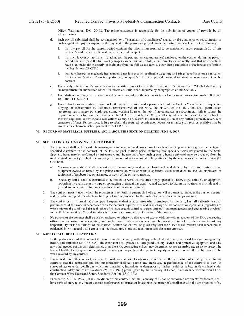
C 202185 (B-2500) Required Contract Provisions Federal-Aid Construction Contracts Dare County
Office, Washington, D.C. 20402. The prime contractor is responsible for the submission of copies of payrolls by all subcontractors.
d. Each payroll submitted shall be accompanied by a "Statement of Compliance," signed by the contractor or subcontractor or his/her agent who pays or supervises the payment of the persons employed under the contract and shall certify the following:
1. that the payroll for the payroll period contains the information required to be maintained under paragraph 2b of this Section V and that such information is correct and complete;
2. that such laborer or mechanic (including each helper, apprentice, and trainee) employed on the contract during the payroll period has been paid the full weekly wages earned, without rebate, either directly or indirectly, and that no deductions have been made either directly or indirectly from the full wages earned, other than permissible deductions as set forth in the Regulations, 29 CFR 3;
3. that each laborer or mechanic has been paid not less that the applicable wage rate and fringe benefits or cash equivalent for the classification of worked performed, as specified in the applicable wage determination incorporated into the contract.
e. The weekly submission of a properly executed certification set forth on the reverse side of Optional Form WH-347 shall satisfy the requirement for submission of the "Statement of Compliance" required by paragraph 2d of this Section V.
f. The falsification of any of the above certifications may subject the contractor to civil or criminal prosecution under 18 U.S.C. 1001 and 31 U.S.C. 231.
g. The contractor or subcontractor shall make the records required under paragraph 2b of this Section V available for inspection, copying, or transcription by authorized representatives of the SHA, the FHWA, or the DOL, and shall permit such representatives to interview employees during working hours on the job. If the contractor or subcontractor fails to submit the required records or to make them available, the SHA, the FHWA, the DOL, or all may, after written notice to the contractor, sponsor, applicant, or owner, take such actions as may be necessary to cause the suspension of any further payment, advance, or guarantee of funds. Furthermore, failure to submit the required records upon request or to make such records available may be grounds for debarment action pursuant to 29 CFR 5.12.
VI. RECORD OF MATERIALS, SUPPLIES, AND LABOR THIS SECTION DELETED JUNE 4, 2007.
VII. SUBLETTING OR ASSIGNING THE CONTRACT 1. The contractor shall perform with its own organization contract work amounting to not less than 30 percent (or a greater percentage if
specified elsewhere in the contract) of the total original contract price, excluding any specialty items designated by the State. Specialty items may be performed by subcontract and the amount of any such specialty items performed may be deducted from the total original contract price before computing the amount of work required to be performed by the contractor's own organization (23 CFR 635).
a. "Its own organization" shall be construed to include only workers employed and paid directly by the prime contractor and equipment owned or rented by the prime contractor, with or without operators. Such term does not include employees or equipment of a subcontractor, assignee, or agent of the prime contractor.
b. "Specialty Items" shall be construed to be limited to work that requires highly specialized knowledge, abilities, or equipment not ordinarily available in the type of contracting organizations qualified and expected to bid on the contract as a whole and in general are to be limited to minor components of the overall contract.
2. The contract amount upon which the requirements set forth in paragraph 1 of Section VII is computed includes the cost of material and manufactured products which are to be purchased or produced by the contractor under the contract provisions.
3. The contractor shall furnish (a) a competent superintendent or supervisor who is employed by the firm, has full authority to direct performance of the work in accordance with the contract requirements, and is in charge of all construction operations (regardless of who performs the work) and (b) such other of its own organizational resources (supervision, management, and engineering services) as the SHA contracting officer determines is necessary to assure the performance of the contract.
4. No portion of the contract shall be sublet, assigned or otherwise disposed of except with the written consent of the SHA contracting officer, or authorized representative, and such consent when given shall not be construed to relieve the contractor of any responsibility for the fulfillment of the contract. Written consent will be given only after the SHA has assured that each subcontract is evidenced in writing and that it contains all pertinent provisions and requirements of the prime contract.
VIII. SAFETY: ACCIDENT PREVENTION 1. In the performance of this contract the contractor shall comply with all applicable Federal, State, and local laws governing safety,
health, and sanitation (23 CFR 635). The contractor shall provide all safeguards, safety devices and protective equipment and take any other needed actions as it determines, or as the SHA contracting officer may determine, to be reasonably necessary to protect the life and health of employees on the job and the safety of the public and to protect property in connection with the performance of the work covered by the contract.
2. It is a condition of this contract, and shall be made a condition of each subcontract, which the contractor enters into pursuant to this contract, that the contractor and any subcontractor shall not permit any employee, in performance of the contract, to work in surroundings or under conditions which are unsanitary, hazardous or dangerous to his/her health or safety, as determined under construction safety and health standards (29 CFR 1926) promulgated by the Secretary of Labor, in accordance with Section 107 of the Contract Work Hours and Safety Standards Act (40 U.S.C. 333).
3. Pursuant to 29 CFR 1926.3, it is a condition of this contract that the Secretary of Labor or authorized representative thereof, shall have right of entry to any site of contract performance to inspect or investigate the matter of compliance with the construction safety
299

C 202185 (B-2500) Required Contract Provisions Federal-Aid Construction Contracts Dare County
and health standards and to carry out the duties of the Secretary under Section 107 of the Contract Work Hours and Safety Standards Act (40 U.S.C. 333).
IX. FALSE STATEMENTS CONCERNING HIGHWAY PROJECTS In order to assure high quality and durable construction in conformity with approved plans and specifications and a high degree of reliability on statements and representations made by engineers, contractors, suppliers, and workers on Federal-aid highway projects, it is essential that all persons concerned with the project perform their functions as carefully, thoroughly, and honestly as possible. Willful falsification, distortion, or misrepresentation with respect to any facts related to the project is a violation of Federal law. To prevent any misunderstanding regarding the seriousness of these and similar acts, the following notice shall be posted on each Federal-aid highway project (23 CFR 635) in one or more places where it is readily available to all persons concerned with the project:
NOTICE TO ALL PERSONNEL ENGAGED ON FEDERAL-AID HIGHWAY PROJECTS 18 U.S.C. 1020 reads as follows:
"Whoever, being an officer, agent, or employee of the United States, or of any State or Territory, or whoever, whether a person, association, firm, or corporation, knowingly makes any false statement, false representation, or false report as to the character, quality, quantity, or cost of the material used or to be used, or the quantity or quality of the work performed or to be performed, or the cost thereof in connection with the submission of plans, maps, specifications, contracts, or costs of construction on any highway or related project submitted for approval to the Secretary of Transportation; or
Whoever knowingly makes any false statement, false representation, false report or false claim with respect to the character, quality, quantity, or cost of any work performed or to be performed, or materials furnished or to be furnished, in connection with the construction of any highway or related project approved by the Secretary of Transportation; or
Whoever knowingly makes any false statement or false representation as to material fact in any statement, certificate, or report submitted pursuant to provisions of the Federal-aid Roads Act approved July 1, 1916, (39 Stat. 355), as amended and supplemented;
Shall be fined not more that $10,000 or imprisoned not more than 5 years or both."
X. IMPLEMENTATION OF CLEAN AIR ACT AND FEDERAL WATER POLLUTION CONTROL ACT (Applicable to all Federal-aid construction contracts and to all related subcontracts of $100,000 or more.)
By submission of this bid or the execution of this contract, or subcontract, as appropriate, the bidder, Federal-aid construction contractor, or subcontractor, as appropriate, will be deemed to have stipulated as follows:
1. That any facility that is or will be utilized in the performance of this contract, unless such contract is exempt under the Clean Air Act, as amended (42 U.S.C. 1857 et seq., as amended by Pub.L. 91-604), and under the Federal Water Pollution Control Act, as amended (33 U.S.C. 1251 et seq., as amended by Pub.L. 92-500), Executive Order 11738, and regulations in implementation thereof (40 CFR 15) is not listed, on the date of contract award, on the U.S. Environmental Protection Agency (EPA) List of Violating Facilities pursuant to 40 CFR 15.20.
2. That the firm agrees to comply and remain in compliance with all the requirements of Section 114 of the Clean Air Act and Section 308 of the Federal Water Pollution Control Act and all regulations and guidelines listed thereunder.
3. That the firm shall promptly notify the SHA of the receipt of any communication from the Director, Office of Federal Activities, EPA, indicating that a facility that is or will be utilized for the contract is under consideration to be listed on the EPA List of Violating Facilities.
4. That the firm agrees to include or cause to be included the requirements of paragraph 1 through 4 of this Section X in every nonexempt subcontract, and further agrees to take such action as the government may direct as a means of enforcing such requirements.
XI. CERTIFICATION REGARDING DEBARMENT, SUSPENSION, INELIGIBILITY AND VOLUNTARY EXCLUSION
1. Instructions for Certification - Primary Covered Transactions: (Applicable to all Federal-aid contracts - 49 CFR 29)
a. By signing and submitting this proposal, the prospective primary participant is providing the certification set out below.
b. The inability of a person to provide the certification set out below will not necessarily result in denial of participation in this covered transaction. The prospective participant shall submit an explanation of why it cannot provide the certification set out below. The certification or explanation will be considered in connection with the department or agency's determination whether to enter into this transaction. However, failure of the prospective primary participant to furnish a certification or an explanation shall disqualify such a person from participation in this transaction.
c. The certification in this clause is a material representation of fact upon which reliance was placed when the department or agency determined to enter into this transaction. If it is later determined that the prospective primary participant knowingly rendered an erroneous certification, in addition to other remedies available to the Federal Government, the department or agency may terminate this transaction for cause of default.
d. The prospective primary participant shall provide immediate written notice to the department or agency to whom this proposal is submitted if any time the prospective primary participant learns that its certification was erroneous when submitted or has become erroneous by reason of changed circumstances.
e. The terms "covered transaction," "debarred," "suspended," "ineligible," "lower tier covered transaction," "participant," "person," "primary covered transaction," "principal," "proposal," and "voluntarily excluded," as used in this clause, have the meanings set out in the Definitions and Coverage sections of rules implementing Executive Order 12549. You may contact the department or agency to which this proposal is submitted for assistance in obtaining a copy of those regulations.
300

C 202185 (B-2500) Required Contract Provisions Federal-Aid Construction Contracts Dare County
f. The prospective primary participant agrees by submitting this proposal that, should the proposed covered transaction be entered into, it shall not knowingly enter into any lower tier covered transaction with a person who is debarred, suspended, declared ineligible, or voluntarily excluded from participation in this covered transaction, unless authorized by the department or agency entering into this transaction.
g. The prospective primary participant further agrees by submitting this proposal that it will include the clause titled "Certification Regarding Debarment, Suspension, Ineligibility and Voluntary Exclusion-Lower Tier Covered Transaction," provided by the department or agency entering into this covered transaction, without modification, in all lower tier covered transactions and in all solicitations for lower tier covered transactions.
h. A participant in a covered transaction may rely upon a certification of a prospective participant in a lower tier covered transaction that is not debarred, suspended, ineligible, or voluntarily excluded from the covered transaction, unless it knows that the certification is erroneous. A participant may decide the method and frequency by which it determines the eligibility of its principals. Each participant may, but is not required to, check the nonprocurement portion of the "Lists of Parties Excluded From Federal Procurement or Nonprocurement Programs" (Nonprocurement List) which is compiled by the General Services Administration.
i. Nothing contained in the foregoing shall be construed to require establishment of a system of records in order to render in good faith the certification required by this clause. The knowledge and information of participant is not required to exceed that which is normally possessed by a prudent person in the ordinary course of business dealings.
j. Except for transactions authorized under paragraph f of these instructions, if a participant in a covered transaction knowingly enters into a lower tier covered transaction with a person who is suspended, debarred, ineligible, or voluntarily excluded from participation in this transaction, in addition to other remedies available to the Federal Government, the department or agency may terminate this transaction for cause or default.
* * * * *
Certification Regarding Debarment, Suspension, Ineligibility and Voluntary Exclusion--Primary Covered Transactions 1. The prospective primary participant certifies to the best of its knowledge and belief, that it and its principals:
a. Are not presently debarred, suspended, proposed for debarment, declared ineligible, or voluntarily excluded from covered transactions by any Federal department or agency;
b. Have not within a 3-year period preceding this proposal been convicted of or had a civil judgement rendered against them for commission of fraud or a criminal offense in connection with obtaining, attempting to obtain, or performing a public (Federal, State or local) transaction or contract under a public transaction; violation of Federal or State antitrust statutes or commission of embezzlement, theft, forgery, bribery, falsification or destruction of records, making false statements, or receiving stolen property;
c. Are not presently indicted for or otherwise criminally or civilly charged by a governmental entity (Federal, State or local) with commission of any of the offenses enumerated in paragraph 1b of this certification; and
d. Have not within a 3-year period preceding this application/proposal had one or more public transactions (Federal, State or local) terminated for cause or default.
2. Where the prospective primary participant is unable to certify to any of the statements in this certification, such prospective participant shall attach an explanation to this proposal.
* * * * *
2. Instructions for Certification - Lower Tier Covered Transactions: (Applicable to all subcontracts, purchase orders and other lower tier transactions of $25,000 or more - 49 CFR 29)
a. By signing and submitting this proposal, the prospective lower tier is providing the certification set out below.
b. The certification in this clause is a material representation of fact upon which reliance was placed when this transaction was entered into. If it is later determined that the prospective lower tier participant knowingly rendered an erroneous certification, in addition to other remedies available to the Federal Government, the department, or agency with which this transaction originated may pursue available remedies, including suspension and/or debarment.
c. The prospective lower tier participant shall provide immediate written notice to the person to which this proposal is submitted if at any time the prospective lower tier participant learns that its certification was erroneous by reason of changed circumstances.
d. The terms "covered transaction," "debarred," "suspended," "ineligible," "primary covered transaction," "participant," "person," "principal," "proposal," and "voluntarily excluded," as used in this clause, have the meanings set out in the Definitions and Coverage sections of rules implementing Executive Order 12549. You may contact the person to which this proposal is submitted for assistance in obtaining a copy of those regulations.
e. The prospective lower tier participant agrees by submitting this proposal that, should the proposed covered transaction be entered into, it shall not knowingly enter into any lower tier covered transaction with a person who is debarred, suspended, declared ineligible, or voluntarily excluded from participation in this covered transaction, unless authorized by the department or agency with which this transaction originated.
f. The prospective lower tier participant further agrees by submitting this proposal that it will include this clause titled "Certification Regarding Debarment, Suspension, Ineligibility and Voluntary Exclusion-Lower Tier Covered Transaction," without modification, in all lower tier covered transactions and in all solicitations for lower tier covered transactions.
301

C 202185 (B-2500) Required Contract Provisions Federal-Aid Construction Contracts Dare County
g. A participant in a covered transaction may rely upon a certification of a prospective participant in a lower tier covered transaction that is not debarred, suspended, ineligible, or voluntarily excluded from the covered transaction, unless it knows that the certification is erroneous. A participant may decide the method and frequency by which it determines the eligibility of its principals. Each participant may, but is not required to, check the Nonprocurement List.
h. Nothing contained in the foregoing shall be construed to require establishment of a system of records in order to render in good faith the certification required by this clause. The knowledge and information of participant is not required to exceed that which is normally possessed by a prudent person in the ordinary course of business dealings.
i. Except for transactions authorized under paragraph e of these instructions, if a participant in a covered transaction knowingly enters into a lower tier covered transaction with a person who is suspended, debarred, ineligible, or voluntarily excluded from participation in this transaction, in addition to other remedies available to the Federal Government, the department or agency with which this transaction originated may pursue available remedies, including suspension and/or debarment.
* * * * *
Certification Regarding Debarment, Suspension, Ineligibility and Voluntary Exclusion--Lower Tier Covered Transactions: 1. The prospective lower tier participant certifies, by submission of this proposal, that neither it nor its principals is presently
debarred, suspended, proposed for debarment, declared ineligible, or voluntarily excluded from participation in this transaction by any Federal department or agency.
2. Where the prospective lower tier participant is unable to certify to any of the statements in this certification, such prospective participant shall attach an explanation to this proposal.
* * * * *
XII. CERTIFICATION REGARDING USE OF CONTRACT FUNDS FOR LOBBYING (Applicable to all Federal-aid construction contracts and to all related subcontracts which exceed $100,000 - 49 CFR 20)
1. The prospective participant certifies, by signing and submitting this bid or proposal, to the best of his or her knowledge and belief, that:
a. No Federal appropriated funds have been paid or will be paid, by or on behalf of the undersigned, to any person for influencing or attempting to influence an officer or employee of any Federal agency, a Member of Congress, an officer or employee of Congress, or an employee of a Member of Congress in connection with the awarding of any Federal contract, the making of any Federal grant, the making of any Federal loan, the entering into of any cooperative agreement, and the extension, continuation, renewal, amendment, or modification of any Federal contract, grant, loan, or cooperative agreement.
b. If any funds other than Federal appropriated funds have been paid or will be paid to any person for influencing or attempting to influence an officer or employee of any Federal agency, a Member of Congress, an officer or employee of Congress, or an employee of a Member of Congress in connection with this Federal contract, grant, loan, or cooperative agreement, the undersigned shall complete and submit Standard Form-LLL, "Disclosure Form to Report Lobbying," in accordance with its instructions.
2. This certification is a material representation of fact upon which reliance was placed when this transaction was made or entered into. Submission of this certification is a prerequisite for making or entering into this transaction imposed by 31 U.S.C. 1352. Any person who fails to file the required certification shall be subject to a civil penalty of not less than $10,000 and not more than $100,000 for each such failure.
3. The prospective participant also agrees by submitting his or her bid or proposal that he or she shall require that the language of this certification be included in all lower tier subcontracts, which exceed $100,000 and that all such recipients shall certify and disclose accordingly.
302

C 202185 (B-2500) General Decision NC20100010 NC 10 Dare County
GENERAL DECISION NC20100010 NC10 Z-11
Date: March 12, 2010
General Decision Number NC20100010 03/12/2010
Superseded General Decision No. NC20080010
State: North Carolina
Construction Type: HIGHWAY
COUNTIES: Alleghany Granville Pasquotank Anson Greene Pender Ashe Halifax Perquimans Avery Harnett Person Beaufort Haywood Pitt Bertie Henderson Polk Bladen Hertford Richmond Brunswick Hoke Robeson Caldwell Hyde Rockingham Camden Iredell Rutherford Carteret Jackson Sampson Caswell Johnston Scotland Chatham Jones Stanly Cherokee Lee Surry Chowan Lenoir Swain Clay Macon Transylvania Cleveland Madison Tyrrell Columbus Martin Vance Craven McDowell Warren Currituck Mitchell Washington Dare Montgomery Watauga Duplin Moore Wayne Edgecombe Nash Wilkes Gates Northampton Wilson Graham Pamlico Yancey
HIGHWAY CONSTRUCTION PROJECTS (does not include tunnels, building structures in rest area projects, railroad construction, and bascule, suspension, and spandrel arch bridges, bridges designed for commercial navigation, and bridges involving marine construction, and other major bridges).
Modification Number Publication Date 0 03/12/2010
303

C 202185 (B-2500) General Decision NC20100010 NC 10 Dare County
SUNC1990-002 02/12/1990 Rates Fringes CARPENTER 7.71 CONCRETE FINISHER 7.64 IRONWORKER (Reinforcing) 9.27 LABORER
General 7.25 Asphalt Raker 7.25 Form Setter (Road) 7.25 Mason (Brick, Block, Stone) 7.76 Pipe Layer 7.25 Power Tool Operator 7.25
POWER EQUIPMENT OPERATORS Asphalt Distributor 7.25 Asphalt Paver 7.25 Bulldozer 7.25 Bulldozer (utility) 7.25 Concrete Finishing Machine 9.48 Concrete Grinder 8.13 Crane, Backhoe, Shovel, & Dragline (Over 1 yd.) 8.53 Crane, Backhoe, Shovel, & Dragline (1 yd. & under) 7.25 Drill Operator 7.65 Grade Checker 7.25 Grease person 7.25 Hydroseeder 7.25 Loader 7.25 Mechanic 8.27 Milling Machine 8.00 Motor Grader (Fine Grade) 8.01 Motor Grader (Rough Grade) 7.42 Oiler 7.25 Piledriver 11.00 Roller (Finish) 7.25 Roller (Rough) 7.25 Scraper 7.25 Screed Asphalt 7.25 Stone Spreader 7.25 Stripping Machine Operator 7.25 Subgrade Machine 9.00 Sweeper 7.25 Tractor (utility) 7.25
TRUCK DRIVERS Single Rear Axle Trucks 7.25 Multi Rear Axle Trucks 7.25 Heavy Duty trucks 7.25 Welder 9.07
304

C 202185 (B-2500) General Decision NC20100010 NC 10 Dare County
Welders – Receive rate prescribed for craft performing operation to which welding is incidental. Unlisted classifications needed for work not included within the scope of the classifications listed may be added after award only as provided in the labor standards contract clauses (29 CFR 5.5(a)(1)(ii)).
In the listing above, the "SU" designation means that rates listed under that identifier do not reflect collectively bargained wage and fringe benefit rates. Other designations indicate unions whose rates have been determined to be prevailing.
WAGE DETERMINATION APPEALS PROCESS
1.) Has there been an initial decision in the matter? This can be:
* an existing published wage determination * a survey underlying a wage determination * a Wage and Hour Division letter setting forth a position on a wage determination matter * a conformance (additional classification and rate) ruling
On survey related matters, initial contact, including requests for summaries of surveys, should be with the Wage and Hour Regional Office for the area in which the survey was conducted because those Regional Offices have responsibility for the Davis-Bacon survey program. If the response from this initial contact is not satisfactory, then the process described in 2.) and 3.) should be followed.
With regard to any other matter not yet ripe for the formal process described here, initial contact should be with the Branch of Construction Wage Determinations. Write to:
Branch of Construction Wage Determinations Wage and Hour Division U. S. Department of Labor 200 Constitution Avenue, N.W. Washington, D.C. 20210
2.) If the answer to the question in 1.) is yes, then an interested party (those affected by the action) can request review and reconsideration from the Wage and Hour Administrator (See 29 CFR Part 1.8 and 29 CFR Part 7). Write to:
Wage and Hour Administrator U.S. Department of Labor 200 Constitution Avenue, N.W. Washington, D.C. 20210
The request should be accompanied by a full statement of the interested party's position and by any information (wage payment data, project description, area practice material, etc.) that the requestor considers relevant to the issue.
3.) If the decision of the Administrator is not favorable, an interested party may appeal directly to the Administrative Review Board (formerly the Wage Appeals Board). Write to:
Administrative Review Board U. S. Department of Labor 200 Constitution Avenue, N.W. Washington, D.C. 20210
4.) All decisions by the Administrative Review Board are final.
END OF GENERAL DECISION
305

C 202185 (B-2500 Division One of Standard Specifications Dare County
*** STANDARD SPECIAL PROVISIONS *** (3-17-10)
DIVISION ONE OF STANDARD SPECIFICATIONS
Division One of the 2006 NCDOT Standard Specifications for Roads and Structures (Standard Specifications) shall apply except as follows:
Definitions: Throughout Division One of the Standard Specifications, the term “Contractor” is replaced with “Design-Build Team”, the term “Bidder” is replaced with “Proposer,” the term “Bid” is replaced by “Price Proposal,” and the phrase “lowest Responsible Bidder” is replaced with “responsible Proposer with the lowest adjusted price.” The replacement of “Contractor” with “Design-Build Team” does not apply to Article 102-2. The replacement of the above terms also does not apply when the terms are part of a phrase (e.g. bid bond, prime contractor, total amount bid, etc.)
Deletions: Articles 102-4, 102-10(C)(2), 102-11(A), 103-2(B), 103-4(B), 104-13, and 108-2 of the Standard Specifications are deleted from Design-Build Contracts.
Modifications: The remainder of this Standard Special Provision includes modifications to Division One of the Standard Specifications.
SECTION 101 DEFINITION OF TERMS
Page 1-2, Article 101-3, replace and add certain definitions as follows:
ADDITIONAL WORK Additional work is that which results from a change or alteration in the contract and for which there are contract unit prices in the original contract or an executed supplemental agreement.
ADVERTISEMENT The public advertisement inviting Statements of Qualifications for the design and construction of specific projects.
AWARD The decision of the Board of Transportation to accept the proposal of the selected Design-Build Team for work which is subject to the furnishing of payment and performance bonds, and such other conditions as may be otherwise provided by law, the Request for Proposals, and the Standard Specifications.
CONTRACT The executed agreement between the Department of Transportation and the successful proposer, covering the performance of the work and the compensation therefor. The term contract is all inclusive with reference to all written agreements affecting a contractual relationship and all documents referred to therein. The contract shall specifically
306

C 202185 (B-2500 Division One of Standard Specifications Dare County include, but not be limited to, the Request for Proposals, the Technical Proposal, the Price Proposal, the printed contract form and all attachments thereto, the contract bonds, the plans and associated special provisions prepared by the Design-Build Team, the standard specifications and all supplemental specifications thereto, the standard special provisions and the project special provisions contained in the Request for Proposals, and all executed supplemental agreements, all of which shall constitute one instrument.
DATE OF AVAILABILITY
That date set forth in the Request for Proposals, by which it is anticipated that the Contract will be executed and preconstruction activities are authorized to begin.
DESIGN-BUILD A form of contracting in which the successful proposer undertakes responsibility for both the design and construction of a project.
DESIGN-BUILD TEAM An individual, partnership, joint venture, corporation or other legal entity that furnishes the necessary design and construction services, whether by itself or through subcontracts.
DESIGN-BUILD PROPOSAL A proposal to contract consisting of a separately sealed Technical Proposal and a separately sealed Price Proposal submitted in response to a Request for Proposals on a Design-Build project.
NOTICE TO PROCEED Written notification from the Department that funds are fully authorized for construction and
that construction may begin provided all pertinent preconstruction requirements of the Request for Proposals are satisfied.
PLANS The project plans, Standard Drawings, working drawings and supplemental drawings, or reproductions thereof, accepted by the Engineer, which show the location, character, dimensions and details of the work to be performed.
(A) Standard Drawings:
Drawings approved for repetitive use, showing details to be used where appropriate. All Standard Drawings approved by the Department plus subsequent revisions and additions. Standard Drawings are available for purchase from:
Randy A. Garris, PE State Contract Officer
1591 Mail Service Center Raleigh, NC 27699-1591
307

C 202185 (B-2500 Division One of Standard Specifications Dare County (B) Preliminary Plans:
Department-furnished drawings included along with a Request for Proposals, or as developed by the Design-Build Team.
(C) Project Plans:
Construction drawings prepared, sealed and completed by the Design-Build Team, or as provided by the Department, that contain specific details and dimensions peculiar to the work.
(D) Working Drawings and Supplemental Drawings:
Supplemental design sheets, shop drawings, or similar data which the Design-Build Team is required to submit to the Engineer.
(E) As-Constructed Drawings:
Final drawings prepared by the Design-Build Team, documenting the details and dimensions of the completed work.
PRICE PROPOSAL The offer of a Proposer, submitted on the prescribed forms, to perform the work and furnish the labor and materials at the price quoted.
PROPOSAL (OR REQUEST FOR PROPOSALS) The paper document provided by the Department that the proposer uses to develop his paper offer to perform the work at designated bid prices.
PROPOSER An individual, partnership, firm, corporation, LLC, or joint venture formally submitting a Technical Proposal and Price Proposal in response to a Request for Proposals.
RIGHT OF WAY The land area shown on the plans as right of way within which the project is to be constructed.
SCHEDULE OF VALUES A schedule of work items necessary to complete work, along with the progress of each work item, primarily for the purpose of partial payments.
TABLE OF QUANTITIES
A listing of work items (corresponding to the items in the Trns*port pay item list) that contributes to a project completion. The table shall include estimated quantities for each work item.
308

C 202185 (B-2500 Division One of Standard Specifications Dare County TECHNICAL PROPOSAL A submittal from a proposer, in accordance with requirements of the Request for Proposals, for the purpose of final selection. The Technical Proposal is defined to also include any supplemental information requested by the Department from a proposer prior to opening bids.
SECTION 102 PROPOSAL REQUIREMENTS AND CONDITIONS
Page 1-11, delete Article 102-1 and replace with the following:
102-1 INVITATION TO BID
After the advertisement has been made, an invitation to bid will be mailed to known prequalified contractors and any other contracting firms, material suppliers, and other interested parties who have requested they be placed on the invitation to bid mailing list informing them that bids will be received for the construction of specific projects. Such invitation will indicate the contract identification number, length, locations, and descriptions; a general summary of the items of work to be performed; and information on how to receive a Request for Qualifications.
All projects will be advertised in daily newspapers throughout the state prior to the bid opening.
Page 1-15, delete Article 102-3 and replace with the following:
102-3 CONTENTS OF REQUEST FOR PROPOSALS A Request for Proposals will be furnished by the Department to the selected proposers from
among the respondents to the Request for Qualifications. Each Request for Proposals will be marked on the front cover by the Department with an identifier of the Proposer to whom it is being furnished. This Request for Proposals will state the location of the project and will show a schedule of contract items for which Technical and Price Proposals are invited. It will set forth the date and time Technical and Price Proposals are to be submitted and will be opened. The Request for Proposals will also include any special provisions or requirements that vary from or are not contained in any preliminary design information or standard specifications.
The Request for Proposals will also include the printed contract forms and signature sheets for execution by both parties to the contract. In the event the Proposer is awarded the contract, execution of the Request for Proposals by the Proposer is considered the same as execution of the contract.
Standard specifications, sealed plans specifically identified as the Department’s responsibility and other documents designated in the Request for Proposals shall be considered a part of the Request for Proposals whether or not they are attached thereto. All papers bound with the proposal are necessary parts thereof and shall not be detached, taken apart, or altered.
The names and identity of each prospective Proposer that receives a copy of the Request for Qualifications for the purposes of submitting a Statement of Qualifications shall be made public, except that a potential Proposer who obtains a Request for Qualifications may, at the time of ordering, request that his name remain confidential.
309

C 202185 (B-2500 Division One of Standard Specifications Dare County Up to three copies of the Request for Proposals will be furnished to each prospective Proposer. Additional copies may be purchased for the sum of $25 each. The copy marked with the Proposer’s name and prequalification number shall be returned to the Department.
Page 1-16, Article 102-6, replace the first paragraph with the following:
The Proposer shall examine carefully the site of the work contemplated, the preliminary plans and specifications, and the Request for Proposals. The submission of a Technical Proposal and a Price Proposal shall be conclusive evidence that the Proposer has investigated and is satisfied as to the conditions to be encountered; as to the character, quality, and scope of work to be performed; the quantities of materials to be furnished; and as to the conditions and requirements of the proposed contract.
Page 1-17, delete Article 102-7 and replace with following:
102-7 SUBSURFACE INVESTIGATION REPORT The Subsurface Investigation and report was made for the purpose of information only. If a subsurface investigation report is available on this project, a copy may be obtained by the prospective proposers upon request. The subsurface investigation on which the report is based was made for the purpose of information only. The various field boring logs, rock cores, and soil test data available may be reviewed or inspected in Raleigh at the office of the Geotechnical Unit. Neither the subsurface investigation report nor the field boring logs, rock cores, or soil test data is part of the contract. General soil and rock strata descriptions and indicated boundaries are based on a geotechnical interpretation of all available subsurface data and may not necessarily reflect the actual subsurface conditions between borings or between sampled strata within the borehole. The laboratory sample data and the in situ (in-place) test data can be relied on only to the degree of reliability inherent in the standard test method. The observed water levels or soil moisture conditions indicated in the subsurface investigations are as recorded at the time of the investigation. These water levels or soil moisture conditions may vary considerably with time according to climatic conditions including temperature, precipitation, and wind, as well as other nonclimatic factors. The Proposer is cautioned that details shown in the subsurface investigation report are preliminary only. The Department does not warrant or guarantee the sufficiency or accuracy of the investigation made, nor the interpretations made or opinions of the Department as to the type of materials and conditions that may be encountered. The proposer is cautioned to make such independent subsurface investigations, as he deems necessary to satisfy himself as to conditions to be encountered on this project. The Design-Build Team shall have no claim for additional compensation or for an extension of time for any reason resulting from the actual conditions encountered at the site differing from those indicated in the subsurface investigation.
Pages 1-17, delete Article 102-8 and replace with the following:
102-8 PREPARATION AND SUBMISSION OF BIDS All Price Proposals shall be prepared and submitted in accordance with the following
requirements:
310

C 202185 (B-2500 Division One of Standard Specifications Dare County
1. The Request for Proposals provided by the Department shall be used and shall not be taken apart or altered. The Price Proposal shall be submitted on the same form, which has been furnished to the Proposer by the Department as identified by the Proposer’s name marked on the front cover by the Department.
2. All entries including signatures shall be written in ink.
3. The Proposer shall submit a lump sum or unit price for every item in the Price Proposal. The lump sum or unit prices bid for the various contract items shall be written in figures.
4. An amount bid shall be entered in the Request for Proposals for every item and the price shall be written in figures in the "Amount Bid" column in the Request for Proposals.
5. The total amount bid shall be written in figures in the proper place in the Request for Proposals. The total amount bid shall be determined by adding the amounts bid for each lump sum item.
6. Changes in any entry shall be made by marking through the entry in ink and making the correct entry adjacent thereto in ink. A representative of the Proposer shall initial the change in ink.
7. The Price Proposal shall be properly executed. In order to constitute proper execution, the Price Proposal shall be executed in strict compliance with the following:
a. If a Price Proposal is by an individual, it shall show the name of the individual and shall be signed by the individual with the word "Individually" appearing under the signature. If the individual operates under a firm name, the bid shall be signed in the name of the individual doing business under the firm name.
b. If the Price Proposal is by a corporation, it shall be executed in the name of the corporation by the President, Vice President, or Assistant Vice President. It shall be attested by the Secretary or Assistant Secretary. The seal of the corporation shall be affixed. If the Price Proposal is executed on behalf of a corporation in any other manner than as above, a certified copy of the minutes of the Board of Directors of said corporation authorizing the manner and style of execution and the authority of the person executing shall be attached to the Price Proposal or shall be on file with the Department.
c. If the Price Proposal is made by a partnership, it shall be executed in the name of the partnership by one of the general partners.
d. If the Price Proposal is made by a Limited Liability Company (LLC), it shall be signed by the manager and notarized.
e. If the Price Proposal is made by a joint venture, it shall be executed by each of the joint venturers in the appropriate manner set out above. In addition, the execution by the joint venturers shall appear below their names.
f. The Price Proposal execution shall be notarized by a notary public whose commission is in effect on the date of execution. Such notarization shall be applicable both to the Price Proposal and to the non-collusion affidavit which is part of the signature sheets.
8. The Price Proposal shall not contain any unauthorized additions, deletions, or conditional bids.
311

C 202185 (B-2500 Division One of Standard Specifications Dare County
9. The Proposer shall not add any provision reserving the right to accept or reject an award, or to enter into a contract pursuant to an award.
10. The Price Proposal shall be accompanied by a bid bond on the form furnished by the Department or by a bid deposit. The bid bond shall be completely and properly executed in accordance with the requirements of Article 102-11. The bid deposit shall be a certified check or cashier check in accordance with Article 102-11.
11. The Price Proposal shall be placed in a sealed envelope and shall have been delivered to and received by the Department prior to the time specified in the Request for Proposals.
Page 1-21, Article 102-11, delete the third paragraph and replace with the following: No bid will be considered or accepted unless accompanied by one of the foregoing securities. The bid bond shall be executed by a Corporate Surety licensed to do business in North Carolina and the certified check or cashiers check shall be drawn on a bank or trust company insured by the Federal Deposit Insurance Corporation and made payable to the Department of Transportation in an amount of at least 5% of the total amount bid for the contract. The condition of the bid bond or bid deposit is: the Principal shall not withdraw its bid within 75 days after the submittal of the same, and if the Board of Transportation shall award a contract to the Principal, the Principal shall within 14 calendar days after the notice of award is received by him give, payment and performance bonds with good and sufficient surety as required for the faithful performance of the contract and for the protection of all persons supplying labor and materials in the prosecution of the work; in the event of the failure of the Principal to give such payment and performance bonds as required, then the amount of the bid bond shall be immediately paid to the Department as liquidated damages, or, in the case of a bid deposit, the deposit shall be forfeited to the Department.
Page 1-22, delete Article 102-12 and replace with the following:
102-12 DELIVERY OF BIDS All Price Proposals shall be placed in a sealed envelope having the name and address of the Proposer, and the statement " Price Proposal for the Design/Build of State Highway Project No. ________________ in ____________County(ies)" on the outside of the envelope. If delivered by mail, the sealed envelope shall be placed in another sealed envelope and the outer envelope addressed to the Contract Officer as stated in the Request for Proposals. The outer envelope shall also bear the statement "Price Proposal for the Design/Build of State Highway Project No. ________________". All Technical Proposals shall be placed in a sealed envelope having the name and address of the Proposer, and the statement "Technical Proposal for the Design/Build of State Highway Project No. ________________ in ____________County(ies)" on the outside of the envelope. If delivered by mail, the sealed envelope shall be placed in another sealed envelope and the outer envelope addressed to the Contract Officer as stated in the Request for Proposal. The outer envelope shall also bear the statement "Technical Proposal for the Design/Build of State Highway Project No. ________________". If delivered in person on or before the due date, the sealed envelope shall be delivered to the office of the Contract Officer as indicated in the Request for Proposals. Price Proposals and Technical Proposals shall be submitted in accordance with the project special provision “Submittal of Proposals” contained elsewhere in this Request for Proposals.
312

C 202185 (B-2500 Division One of Standard Specifications Dare County All Price Proposals and Technical Proposals shall be delivered prior to the time specified in the Request for Proposals. Price proposals and Technical Proposals received after such time will not be accepted and will be returned to the Proposer unopened.
Pages 1-22, delete Article 102-13 and replace with the following:
102-13 WITHDRAWAL OR REVISION OF BIDS A Design-Build Team will not be permitted to withdraw its Technical and Price Proposals after they have been submitted to the Department, unless allowed under Article 103-3 or unless otherwise approved by the State Highway Administrator.
Page 1-23, delete Article 102-14 and replace with the following:
102-14 RECEIPT AND OPENING OF BIDS Price Proposals will be opened and read publicly at the time and place indicated in the Request for Proposals. The scores of the previously conducted evaluation of the Technical Proposals will also be read publicly in accordance with the procedures outlined in the Request for Proposals. Proposers, their authorized agents, and other interested parties are invited to be present.
Page 1-23, Article 102-15, Replace the 1st paragraph with the following:
102-15 REJECTION OF BIDS Any Price Proposal submitted which fails to comply with any of the requirements of Articles 102-8, 102-10 or 102-11, or with the requirements of the project scope and functional specifications shall be considered irregular and may be rejected. A Price Proposal that does not contain costs for all proposal items shall be considered irregular and may be rejected.
SECTION 103 AWARD AND EXECUTION OF CONTRACT
Page 1-25, delete Article 103-1 and replace with the following:
103-1 CONSIDERATION OF PRICE PROPOSALS After the Price Proposals are opened and read, they will be tabulated. The Price Proposal and score of the Technical Proposal will be made available in accordance with procedures outlined in the Request for Proposals. In the event of errors, omissions, or discrepancies in the costs, corrections to the Price Proposal will be made in accordance with the provisions of Article 103-2. Such corrected costs will be used to determine the lowest adjusted price.
After the reading of the Price Proposals and technical scores, the Department will calculate the lowest adjusted price as described in the “Selection Procedure” section of the Request for Proposals.
The right is reserved to reject any or all Price Proposals, to waive technicalities, to request the Proposer with the lowest adjusted price to submit an up-to-date financial and operating
313

C 202185 (B-2500 Division One of Standard Specifications Dare County statement, to advertise for new proposals, or to proceed to do the work otherwise, if in the judgment of the Board, the best interests of the State will be promoted thereby.
Page 1-26, Subarticle 103-2(A), add items (7) and (8) as follows:
(7) Discrepancy in the “Total Amount Bid” and the addition of the “Amount Bid” for each line Item In the case of the Total Amount Bid does not equal the summation of each Amount Bid for the line items, the summation of each Amount Bid for the line items shall be deemed to be the correct total for the entire project.
(8) Omitted Total Amount Bid –Amount Bid Completed
If the Total Amount Bid is not completed and the Amount Bid for all line items is completed the Total Amount Bid shall be the summation of the Amount Bid for all line items.
Page 1-28, Subarticle 103-4(A), replace the fourth sentence with the following:
The notice of award, if the award be made, will be issued within 75 days after the submittal of bids, except that with the consent of the lowest responsible bidder the decision to award the contract to such bidder may be delayed for as long a time as may be agreed upon by the Department and such bidder.
Page 1-29, delete Article 103-6 and replace with the following:
103-6 RETURN OF BID BOND OR BID DEPOSIT
Checks that have been furnished as a bid deposit will be retained until after the contract bonds have been furnished by the successful proposer, at which time Department of Transportation warrants in the equivalent amount of checks that were furnished as a bid deposit will be issued. Paper bid bonds will be retained by the Department until the contract bonds are furnished by the successful proposer, after which all such bid bonds will be destroyed unless the individual bid bond form contains a note requesting that it be returned to the proposer or the Surety.
Page 1-30, delete Article 103-9 and replace with the following:
103-9 FAILURE TO FURNISH CONTRACT BONDS The successful proposer's failure to file acceptable bonds within 14 calendar days after the notice of award is received by him shall be just cause for the forfeiture of the bid bond or bid deposit and rescinding the award of the contract. Award may then be made to the responsible proposer with the next lowest adjusted price or the work may be readvertised and constructed under contract or otherwise, as the Board of Transportation may decide.
314

C 202185 (B-2500 Division One of Standard Specifications Dare County
SECTION 104
SCOPE OF WORK
Page 1-30, delete Article 104-1 and replace with the following:
104-1 INTENT OF CONTRACT The intent of the contract is to prescribe the work or improvements that the Design-Build Team undertakes to perform, in full compliance with the contract. In case the method or character of any part of the work is not covered by the contract, this section shall apply. The Design-Build Team shall perform all work in accordance with the contract or as may be modified by written orders, and shall do such special, additional, extra, and incidental work as may be considered necessary to complete the work to the full intent of the contract. Unless otherwise provided elsewhere in the contract, the Design-Build Team shall furnish all implements, machinery, equipment, tools, materials, supplies, transportation, and labor necessary for the design, prosecution and completion of the work.
Page 1-31, Article 104-3, replace “plans or details of construction” with “contract” in all instances within this Article.
Page 1-40, Article 104-10, replace the first paragraph with the following:
104-10 MAINTENANCE OF THE PROJECT The Design-Build Team shall maintain the project from the date of beginning construction on the project until the project is finally accepted. For sections of facilities impacted by utility construction / relocation performed by the Design-Build Team prior to beginning construction on the roadway project, maintenance of the impacted sections of facilities shall be performed by the Design-Build Team beginning concurrently with the impact. All existing and constructed guardrail / guiderail within the project limits shall be included in this maintenance. This maintenance shall be continuous and effective and shall be prosecuted with adequate equipment and forces to the end that all work covered by the contract is kept in satisfactory and acceptable conditions at all times. The Design-Build Team shall perform weekly inspections of guardrail and guiderail and shall report damages to the Engineer on the same day of the weekly inspection. Where damaged guardrail or guiderail is repaired or replaced as a result of maintaining the project in accordance with this Article, such repair or replacement shall be performed within 7 consecutive calendar days of such inspection report. Page 1-41, Article 104-10, add the following after the last paragraph: The Design-Build Team will not be compensated for performance of weekly inspections and damage reports for the guardrail / guiderail. Other maintenance activities for existing guardrail / guiderail will be handled in accordance with Articles 104-7 and 104-8.
315

C 202185 (B-2500 Division One of Standard Specifications Dare County
SECTION 105 CONTROL OF WORK
Pages 1-46, delete Article 105-2 and replace with the following:
105-2 PLANS AND WORKING DRAWINGS All plans shall be supplemented by such approved working drawings as are necessary to adequately control the work. Working drawings furnished by the Design-Build Team and approved by the Engineer shall consist of such detailed drawings as may be required to adequately control the work. They may include stress sheets, shop drawings, erection drawings, falsework drawings, cofferdam drawings, bending diagrams for reinforcing steel, catalog cuts, or any other supplementary drawings or similar data required of the Design-Build Team. When working drawings are approved by the Engineer, such approval shall not operate to relieve the Design-Build Team of any of his responsibility under the contract for the successful completion of the work. Changes on shop drawings after approval and/or distribution shall be subject to the approval of the Engineer and he shall be furnished a record of such changes.
Page 1-47, Article 105-3, add the following after the 3rd paragraph: The Design-Build Team shall bear all the costs of providing the burden of proof that the nonconforming work is reasonable and adequately addresses the design purpose. The Design-Build Team shall bear all risk for continuing with nonconforming work in question until it is accepted. The Engineer may impose conditions for acceptance of the nonconforming work. The Design-Build Team shall bear all costs for fulfilling the conditions. The decisions whether the product satisfies the design purpose, whether the nonconforming work is reasonably acceptable and the conditions for acceptance are at the sole discretion of the Engineer.
Pages 1-47, delete Article 105-4 and replace with the following:
105-4 COORDINATION OF PLANS, SPECIFICATIONS, SUPPLEMENTAL SPECIFICATIONS, AND SPECIAL PROVISIONS
The Request for Proposals, all Plans, the Standard Specifications, and all supplementary documents are essential parts of the contract and a requirement occurring in one is as binding as though occurring in all. They are intended to be complementary and to describe and provide for a complete work. In case of discrepancy or conflict, the order in which they govern shall be as follows: (A) Request for Proposals (B) Technical Proposal from the Design-Build Team (C) Accepted Plans and Details from the Design-Build Team, or sealed plans provided by the Department, as applicable (D) Standard Drawings (E) Standard Specifications
316

C 202185 (B-2500 Division One of Standard Specifications Dare County Where dimensions on the plans are given or can be computed from other given dimensions they shall govern over scaled dimensions. The Design-Build Team shall take no advantage of any error or omission in the plans, estimated quantities, or specifications. In the event the Design-Build Team discovers an error or omission, he shall immediately notify the Engineer.
Page 1-50, delete Article 105-9 and replace with the following:
105-9 CONTRUCTION STAKES, LINES, AND GRADES The Design-Build Team shall be responsible for any surveying, construction staking and layout required in the performance of the work. He will be responsible for the accuracy of lines, slopes, grades and other engineering work which he provides under this contract. Unless otherwise specified in the Request for Proposals, no measurement or direct payment will be made for this work. The cost shall be considered as included in other contract items.
SECTION 106 CONTROL OF MATERIAL
Page 1-56, Article 106-2, add the following after the second paragraph:
Prior to beginning construction, the Design-Build Team shall provide a Table of Quantities as described in Article 101-3 of these specifications.
The Table of Quantities Work Items shall correspond to Pay Items as defined in the Standard Specifications. These Work Items have associated Materials and Conversion Factors. For non-standard Work Items, a Generic Work Item with the correct Unit of Measure and in an appropriate category will be used. For example, “GENERIC TRAFFIC CONTROL ITEM – EA” or “GENERIC RETAINING WALL ITEM – LF”. For these Generic Work Items, Materials must be defined and appropriate conversion factors submitted.
An initial Table of Quantities shall be submitted no later than 30 calendar days after the date of award. The Table of Quantities shall be updated and resubmitted within 14 days of when a set of Plans is sealed as Release for Construction (RFC) Plans, and whenever there are substantial changes to the Quantities on previously incorporated RFC Plans.
Page 1-58, Article 106-6, replace “specifications” with “contract” as the last word of the 1st paragraph. Page 1-58, Article 106-6(C), replace the 2nd paragraph with the following:
Where the Department agrees to inspect or test materials during their production or at the source of supply, the Design-Build Team shall bear the cost of testing performed on materials ordered by him but not incorporated into the project. For items normally pretested by the Department, the Design-Build Team shall provide a minimum of 30 days notice prior to the beginning of production of the items for this project along with final approved shop drawings.
317

C 202185 (B-2500 Division One of Standard Specifications Dare County
SECTION 107 LEGAL RELATIONS AND RESPONSIBILITY
TO PUBLIC
Page 1-60, Article 107-2, delete the entire article and replace with the following:
In accordance with G.S. 143B-426.40A, the Department will not recognize any assignment of claims by any Contractor against the Department.
Page 1-69, Article 107-18, in the last sentence of the first paragraph, replace the word “legally” with the word “contractually”.
Page 1-69, delete Article 107-19 and replace with the following:
107-19 FURNISHING RIGHT OF WAY The responsibility for coordinating the securing of all necessary rights of way is as outlined in the Request for Proposals.
SECTION 108 PROSECUTION AND PROGRESS
Page 1-71, Article 108-1, add the following sentence to the end of the 1st paragraph:
The Design-Build Team shall not commence work prior to execution of the contract by both the Department and the Design-Build Team.
Page 1-72, delete Article 108-3 and replace with the following:
108-3 PRECONSTRUCTION AND PRE-DESIGN CONFERENCES
The selected Design-Build Team shall meet with the Engineer for a pre-design conference concerning the design phase of the work. This conference shall be held prior to the commencement of work, as it is determined according to Article 108-1, and will be scheduled by the Engineer. At the predesign conference, the Design-Build Team shall furnish authorized signature forms and a list of any proposed subcontractors associated with the design of the project.
A preconstruction conference shall be held at least 10 working days before construction activity begins. This second conference, concerning the construction phase, shall also be scheduled by the Engineer. The Design-Build Team shall give the Engineer a minimum of 45 days notice before he plans to begin construction activities. This will allow the Engineer time for any environmental agency representatives involved in the permitting process, as well as any other pertinent entities, to be scheduled to attend the preconstruction conference. If the Design-Build Team is responsible for utilities in accordance with Article 105-8 and the Request for Proposals, he shall be responsible for coordinating with the Engineer in scheduling their attendance and for notifying them. The Design-Build Team shall also be responsible for
318

C 202185 (B-2500 Division One of Standard Specifications Dare County coordinating with the Engineer in scheduling the attendance of subcontractors and others deemed appropriate, and for notifying them.
At the preconstruction conference, a list of any proposed subcontractors and major material suppliers associated with the construction of the project will be submitted.
If the contract has a DBE requirement, the Design-Build Team shall submit copies of completed and signed DBE subcontracts, purchase orders, or invoices to the Department.
The Design-Build Team shall submit a traffic control plan in accordance with Article 1101-5 and the Request for Proposals. The Design-Build Team shall designate an employee who is competent and experienced in traffic control to implement and monitor the traffic control plan. The qualifications of the designated employee must be satisfactory to the Engineer.
The Design-Build Team shall submit a safety plan and designate an employee as Safety Supervisor.
Both plans shall be submitted at the preconstruction conference and must be satisfactory to the Engineer. Should the design plan include activities that would place personnel on the work site, traffic control and safety plans for those activities shall be submitted at the predesign conference.
During the preconstruction conference, the Engineer will designate a Department employee or employees who will be responsible to see that the traffic control plans and any alterations thereto are implemented and monitored to the end that traffic is carried through the work in an effective manner. If approved by the Engineer, the Design-Build Team may designate one employee to be responsible for both the traffic control and safety plans. The Design-Build Team shall not designate its superintendent as the responsible person for either the traffic control plan or the safety plan, unless approved by the Engineer.
If the project requires that Design-Build Team or State personnel work from falsework, within shoring, or in any other hazardous area the Design-Build Team shall submit, as part of the Design-Build Team's safety plan, specific measures it will use to ensure worker safety.
The Design-Build Team shall also submit a program for erosion control and pollution prevention on all projects involving clearing and grubbing, earthwork, structural work, or other construction, when such work is likely to create erosion or pollution problems.
If the Design-Build Team fails to provide the required submissions, the Engineer may order the preconstruction conference suspended until such time as they are furnished. Work shall not begin until the preconstruction conference has been concluded and the safety plan has been approved, unless authorized by the Engineer. The Design-Build Team shall not be entitled to additional compensation or an extension of contract time resulting from any delays due to such a suspension.
The Design-Build Team shall designate a qualified employee as Quality Control Manager. The Quality Control Manager shall be responsible for implementing and monitoring the quality control requirements of the project.
319

C 202185 (B-2500 Division One of Standard Specifications Dare County Page 1-72, Article 108-4, add the following sentence to the end of this article:
The Design-Build Team shall record the proceedings of these conferences and distribute the final minutes of the conferences to all attendees.
Page 1-74, Article 108-6, replace “40 percent” with “30 percent” in the 1st paragraph.
Page 1-74, Article 108-6, delete the second paragraph and replace with the following:
In any event, the Contractor shall perform with his own organization work amounting to not less than 25% of the difference between the total amount bid and the value of specialty items that have been sublet.
Pages 1-75, delete Article 108-8 and replace with the following:
108-8 FAILURE TO MAINTAIN SATISFACTORY PROGRESS The Engineer will check the Design-Build Team’s progress at the time each partial pay request is received. The Design-Build Team’s progress may be considered as unsatisfactory if, according to the Progress schedule, the projected finish date for all work exceeds the scheduled finish date by more than 10%.
When the Design-Build Team's progress is found to be unsatisfactory as described above, the Engineer may make written demand of the Design-Build Team to state in writing the reason for the unsatisfactory progress and produce such supporting data as the Engineer may require or the Design-Build Team may desire to submit. The Engineer will consider the justifications submitted by the Design-Build Team and extensions of the completion date that have or may be allowed in accordance with Article 108-10(B).
When the Design-Build Team cannot satisfactorily justify the unsatisfactory progress the Engineer may invoke one or more of the following sanctions:
1. Withhold anticipated liquidated damages from amounts currently due or which become due.
2. Remove the Design-Build Team and individual managing firms of the Design-Build Team and/or prequalified design firms from the Department’s Prequalified Bidders List.
When any of the above sanctions have been invoked, they shall remain in effect until rescinded by the Engineer.
Page 1-79, Article 108-10(B), add the following as the first paragraph:
Only delays to activities which affect the completion date or intermediate contract date will be considered for an extension of contract time. No extensions will be granted until a delay occurs which impacts the project’s critical path and extends the work beyond the contract completion date or intermediate completion date. Any extension to the completion date or intermediate contract date will be based on the number of calendar days the completion date or intermediate completion date is impacted as determined by the Engineer’s analysis.
Pages 1-79, delete Subarticle 108-10(B)(1) in its entirety.
320

C 202185 (B-2500 Division One of Standard Specifications Dare County Page 1-82, delete bullet (A)(2) in its entirety.
Page 1-83, Article 108-13, delete bullet (E)(2) in its entirety.
Page 1-84, Article 108-13, add the following:
(F) In the event that the contract is terminated prior to issuance of all permits necessary to complete the project, cumulative payments made to the Design-Build Team under Article 108-13(E) will not exceed $17 Million. In such case, all completed or partially completed work products shall become the property of the Department including but not limited to, geotechnical investigation boring logs, inventory, recommendations, hydraulic models and recommendations, as well as all design files, plans and specifications prepared in anticipation of construction. These work products shall be submitted in both hard copy and usable electronic format.
SECTION 109
MEASUREMENT AND PAYMENT
Page 1-85, Article 109-2, delete the last sentence of the 1st paragraph and replace with the following:
Payment to the Design-Build Team will be made only for the work completed, certified and accepted in accordance with the terms of the contract.
Pages 1-90, delete Article 109-4(A) and replace with the following:
109-4 PARTIAL PAYMENTS
(A) General: Partial payments will be based upon progress estimates prepared by the Engineer at least
once each month on the date established by the Engineer. Partial payments may be made twice each month if in the judgment of the Engineer the amount of work performed is sufficient to warrant such payment. No partial payment will be made when the total value of work performed since the last partial payment amounts to less than $10,000.00. Partial payments will be approximate only and will be subject to correction in the final estimate and payment.
When the contract includes one lump sum price for the entire work required by the contract, partial payments for the lump sum design-build price shall be based on a certified Schedule of Values submitted by the successful Design-Build Team and approved by the Engineer. The certification shall indicate the Design-Build Team has reviewed the information submitted and the information accurately represents the work performed for which payment is requested. The certified Schedule of Values shall be submitted no later than 30 calendar days after the date of award. Each item on the certified Schedule of Values shall be assigned a cost and quantity and shall be identified as an activity on the progress schedule. A revised certified Schedule of Values shall be submitted with each update of the Progress schedule as described in Article 108-2 or
321

C 202185 (B-2500 Division One of Standard Specifications Dare County
when requested by the Engineer. A certified copy of the Table of Quantities shall also be submitted with each payment request. The certification of the Table of Quantities shall indicate the Design-Build Team has reviewed the information submitted and the information accurately represents the materials for the work performed for which payment is requested.
When the contract includes lump sum items for portions of the work required by the contract, and the applicable section of the Specifications or Request for Proposals specify the means by which the total amount bid be included in the partial pay estimates, the Engineer will determine amounts due on the partial pay estimate in accordance with the applicable portion of the Specifications or Request for Proposals.
The Engineer will withhold an amount sufficient to cover anticipated liquidated damages as determined by the Engineer.
Page 1-92, Subarticle 109-5(D), delete the 4th and 5th paragraphs and replace with the following:
Partial payments will not be made on seed or any living or perishable plant materials.
Partial payment requests shall not be submitted by the Design-Build Team until those items requested have corresponding signed and sealed RFC plans accepted by the Department.
Pages 1-94, Article 109-10, add the following as bullets (E) and (F) under the 1st paragraph.
(E) As-constructed plans or other submittals as required by the Contract.
(F) Documents or guarantees to support any warranty provided by the Design Build Team.
322
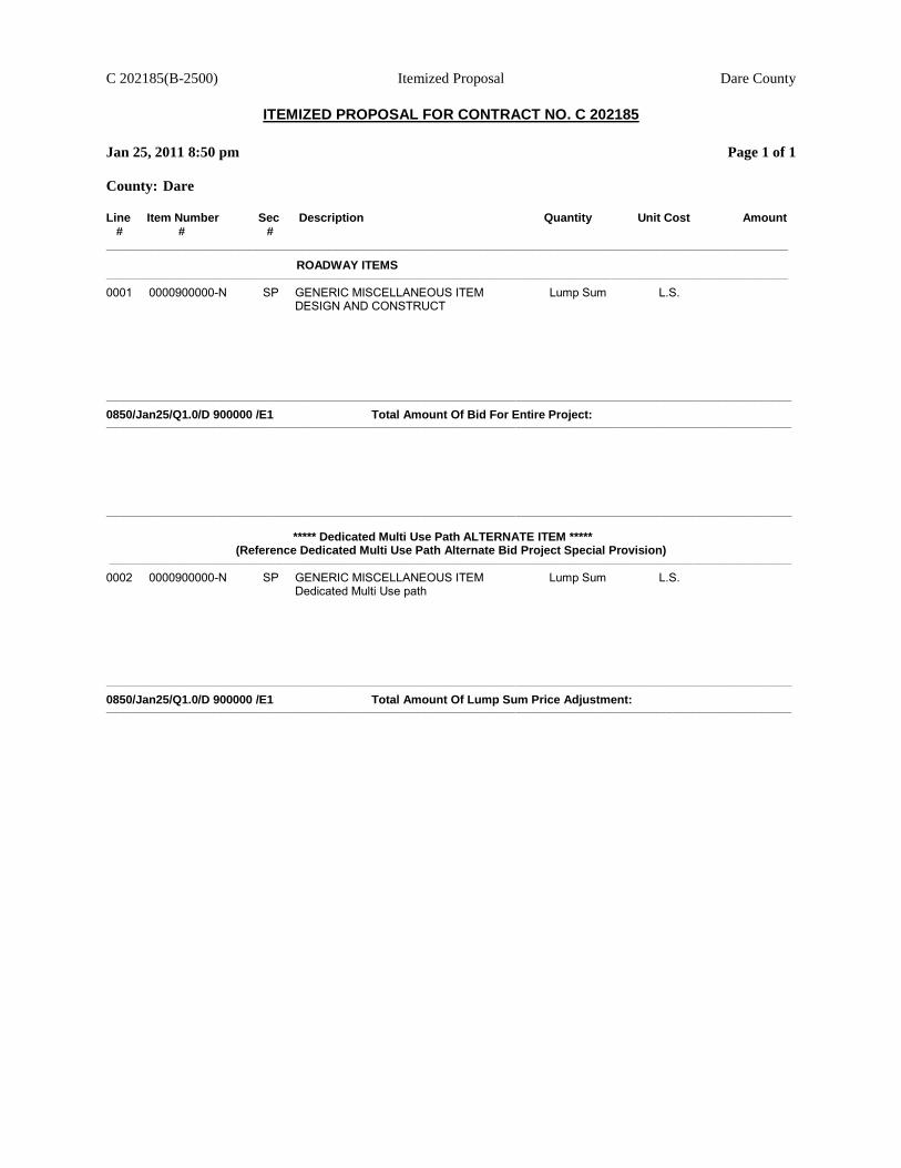
C 202185(B-2500) Itemized Proposal Dare County
ITEMIZED PROPOSAL FOR CONTRACT NO. C 202185
Jan 25, 2011 8:50 pm Page 1 of 1
County: Dare
Line Item Number Sec Description Quantity Unit Cost Amount # # # ________________________________________________________________________________________________________
ROADWAY ITEMS ________________________________________________________________________________________________________________________________________________________________________________________________________________
0001 0000900000-N SP GENERIC MISCELLANEOUS ITEM Lump Sum L.S. DESIGN AND CONSTRUCT
_________________________________________________________________________________________________________________________________________________________________________________________________________________
0850/Jan25/Q1.0/D 900000 /E1 Total Amount Of Bid For Entire Project: _________________________________________________________________________________________________________________________________________________________________________________________________________________
_________________________________________________________________________________________________________________________________________________________________________________________________________________
***** Dedicated Multi Use Path ALTERNATE ITEM *****
(Reference Dedicated Multi Use Path Alternate Bid Project Special Provision) ________________________________________________________________________________________________________________________________________________________________________________________________________________
0002 0000900000-N SP GENERIC MISCELLANEOUS ITEM Lump Sum L.S. Dedicated Multi Use path
_________________________________________________________________________________________________________________________________________________________________________________________________________________
0850/Jan25/Q1.0/D 900000 /E1 Total Amount Of Lump Sum Price Adjustment: _________________________________________________________________________________________________________________________________________________________________________________________________________________
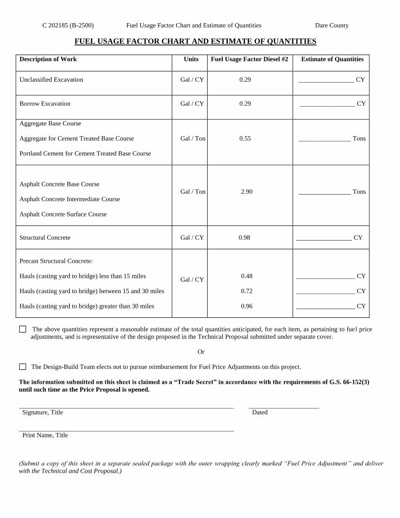
C 202185 (B-2500) Fuel Usage Factor Chart and Estimate of Quantities Dare County
FUEL USAGE FACTOR CHART AND ESTIMATE OF QUANTITIES
Description of Work Units Fuel Usage Factor Diesel #2 Estimate of Quantities
Unclassified Excavation Gal / CY 0.29 _________________ CY
Borrow Excavation Gal / CY 0.29 _________________ CY
Aggregate Base Course
Aggregate for Cement Treated Base Course
Portland Cement for Cement Treated Base Course
Gal / Ton 0.55 ________________ Tons
Asphalt Concrete Base Course
Asphalt Concrete Intermediate Course
Asphalt Concrete Surface Course
Gal / Ton 2.90 ________________ Tons
Structural Concrete Gal / CY 0.98 _________________ CY
Precast Structural Concrete:
Hauls (casting yard to bridge) less than 15 miles
Hauls (casting yard to bridge) between 15 and 30 miles
Hauls (casting yard to bridge) greater than 30 miles
Gal / CY
0.48
0.72
0.96
__________________ CY
__________________ CY
__________________ CY
The above quantities represent a reasonable estimate of the total quantities anticipated, for each item, as pertaining to fuel price
adjustments, and is representative of the design proposed in the Technical Proposal submitted under separate cover.
Or
The Design-Build Team elects not to pursue reimbursement for Fuel Price Adjustments on this project.
The information submitted on this sheet is claimed as a “Trade Secret” in accordance with the requirements of G.S. 66-152(3)
until such time as the Price Proposal is opened.
Signature, Title
Dated
Print Name, Title
(Submit a copy of this sheet in a separate sealed package with the outer wrapping clearly marked “Fuel Price Adjustment” and deliver
with the Technical and Cost Proposal.)

C 2
02
18
5 (
B-2
50
0)
Lis
ting o
f D
BE
Sub
contr
acto
rs
Dar
e C
ounty
LIS
TIN
G O
F D
BE
SU
BC
ON
TR
AC
TO
RS
S
hee
t _
__
_ o
f _
__
_
FIR
M N
AM
E A
ND
AD
DR
ES
S
ITE
M N
O.
ITE
M D
ES
CR
IPT
ION
(*)
AG
RE
ED
UP
ON
UN
IT P
RIC
E
DO
LL
AR
VO
LU
ME
OF
SU
BL
ET
IT
EM
CO
NT
RA
CT
NO
.____________________ C
OU
NT
Y________________________________ F
IRM
________________________
TH
IS F
OR
M M
US
T B
E C
OM
PL
ET
ED
IN
OR
DE
R F
OR
TH
E B
ID T
O B
E C
ON
SID
ER
ED
RE
SP
ON
SIV
E A
ND
BE
PU
BL
ICL
Y R
EA
D.
BID
DE
RS
WIT
H N
O D
BE
PA
RT
ICIP
AT
ION
MU
ST
SO
IN
DIC
AT
E T
HIS
ON
TH
E F
OR
M B
Y E
NT
ER
ING
TH
E W
OR
D O
R N
UM
BE
R Z
ER
O.

C 2
02
18
5 (
B-2
50
0)
Lis
ting o
f D
BE
Sub
contr
acto
rs
Dar
e C
ounty
LIS
TIN
G O
F D
BE
SU
BC
ON
TR
AC
TO
RS
S
hee
t _
__
_ o
f _
__
_
FIR
M N
AM
E A
ND
AD
DR
ES
S
ITE
M N
O.
ITE
M D
ES
CR
IPT
ION
(*)
AG
RE
ED
UP
ON
UN
IT P
RIC
E
DO
LL
AR
VO
LU
ME
OF
SU
BL
ET
IT
EM
CO
NT
RA
CT
NO
.____________________ C
OU
NT
Y________________________________ F
IRM
________________________

C 2
02
18
5 (
B-2
50
0)
Lis
ting o
f D
BE
Sub
contr
acto
rs
Dar
e C
ounty
LIS
TIN
G O
F D
BE
SU
BC
ON
TR
AC
TO
RS
S
hee
t _
__
_ o
f _
__
_
FIR
M N
AM
E A
ND
AD
DR
ES
S
ITE
M N
O.
ITE
M D
ES
CR
IPT
ION
(*)
AG
RE
ED
UP
ON
UN
IT P
RIC
E
DO
LL
AR
VO
LU
ME
OF
SU
BL
ET
IT
EM
CO
NT
RA
CT
NO
.____________________ C
OU
NT
Y________________________________ F
IRM
________________
________

C 2
02
18
5 (
B-2
50
0)
Lis
ting o
f D
BE
Sub
contr
acto
rs
Dar
e C
ounty
LIS
TIN
G O
F D
BE
SU
BC
ON
TR
AC
TO
RS
S
hee
t _
__
_ o
f _
__
_
FIR
M N
AM
E A
ND
AD
DR
ES
S
ITE
M N
O.
ITE
M D
ES
CR
IPT
ION
(*)
AG
RE
ED
UP
ON
UN
IT P
RIC
E
DO
LL
AR
VO
LU
ME
OF
SU
BL
ET
IT
EM
CO
NT
RA
CT
NO
.____
___________
_____ C
OU
NT
Y________________________________ F
IRM
________________________
CO
ST
OF
CO
NS
TR
UC
TIO
N W
OR
K O
NL
Y
$ ________________________________________________________
(*
) T
he
Do
llar
Vo
lum
e S
ho
wn I
n T
his
Co
lum
n S
hal
l b
e
**D
oll
ar V
olu
me
of
DB
E S
ub
contr
acto
r $
__
__
__
__
__
__
__
__
__
__
__
__
__
__
__
__
__
__
Act
ual
Pri
ce A
gre
ed U
po
n b
y t
he
Pri
me
Co
ntr
acto
r an
d t
he
DB
E S
ub
contr
acto
r, a
nd
Thes
e P
rice
s W
ill
Be
Use
d t
o D
eter
min
e
Per
centa
ge
of
To
tal
Co
nst
ruct
ion C
ost
__
__
__
__
__
__
__
__%
The
Per
centa
ge
of
the
DB
E P
arti
cip
atio
n i
n t
his
Co
ntr
act.
(I
ncl
ud
ing R
ight-
of-
Way
Acq
uis
itio
n S
ervic
es)
**
MU
ST
HA
VE
EN
TR
Y E
VE
N I
F F
IGU
RE
TO
BE
EN
TE
RE
D I
S Z
ER
O.

C202185 (B-2500) Execution of Bid, Non-Collusion Affidavit, Debarment Certification Dare County
and Gift Ban Certification
Rev. 7-12-10
EXECUTION OF BID
NON-COLLUSION AFFIDAVIT, DEBARMENT CERTIFICATION AND GIFT BAN CERTIFICATION
CORPORATION
The person executing the bid, on behalf of the Bidder, being duly sworn, solemnly swears (or affirms) that neither he, nor any
official, agent or employee of the bidder has entered into any agreement, participated in any collusion, or otherwise taken any
action which is in restraint of free competitive bidding in connection with any bid or contract, that the bidder has not been
convicted of violating N.C.G.S. § 133-24 within the last three years, and that the Bidder intends to do the work with its own
bonafide employees or subcontractors and is not bidding for the benefit of another contractor.
In addition, execution of this bid in the proper manner also constitutes the Bidder's certification of status under penalty of perjury
under the laws of the United States in accordance with the Debarment Certification attached, provided that the Debarment
Certification also includes any required statements concerning exceptions that are applicable.
N.C.G.S. § 133-32 and Executive Order 24 prohibit the offer to, or acceptance by, any State Employee of any gift from anyone
with a contract with the State, or from any person seeking to do business with the State. By execution of any response in this
procurement, you attest, for your entire organization and its employees or agents, that you are not aware that any such gift has
been offered, accepted, or promised by any employees of your organization.
SIGNATURE OF CONTRACTOR
Full name of Corporation
Address as prequalified
Attest By Secretary/Assistant Secretary President/Vice President/Assistant Vice President
Select appropriate title Select appropriate title
Print or type Signer's name Print or type Signer's name
CORPORATE SEAL
AFFIDAVIT MUST BE NOTARIZED
Subscribed and sworn to before me this the
_______ day of _______________, 20_____
Signature of Notary Public
Of __________________________County
State of ___________________________
My Commission Expires _______________
NOTARY SEAL

C202185 (B-2500) Execution of Bid, Non-Collusion Affidavit, Debarment Certification Dare County
and Gift Ban Certification
Rev. 7-12-10
EXECUTION OF BID
NON-COLLUSION AFFIDAVIT, DEBARMENT CERTIFICATION AND GIFT BAN CERTIFICATION
PARTNERSHIP
The person executing the bid, on behalf of the Bidder, being duly sworn, solemnly swears (or affirms) that neither
he, nor any official, agent or employee of the bidder has entered into any agreement, participated in any collusion, or
otherwise taken any action which is in restraint of free competitive bidding in connection with any bid or contract,
that the bidder has not been convicted of violating N.C.G.S. § 133-24 within the last three years, and that the Bidder intends to
do the work with its own bonafide employees or subcontractors and is not bidding for the benefit of another
contractor.
In addition, execution of this bid in the proper manner also constitutes the Bidder's certification of status under
penalty of perjury under the laws of the United States in accordance with the Debarment Certification attached,
provided that the Debarment Certification also includes any required statements concerning exceptions that are
applicable.
N.C.G.S. § 133-32 and Executive Order 24 prohibit the offer to, or acceptance by, any State Employee of any gift
from anyone with a contract with the State, or from any person seeking to do business with the State. By execution
of any response in this procurement, you attest, for your entire organization and its employees or agents, that you are
not aware that any such gift has been offered, accepted, or promised by any employees of your organization.
SIGNATURE OF CONTRACTOR
Full Name of Partnership
Address as Prequalified
By Signature of Witness Signature of Partner
Print or type Signer's name Print or type Signer's name
AFFIDAVIT MUST BE NOTARIZED
Subscribed and sworn to before me this the
day of _____________________ 20_____.
Signature of Notary Public
of ____________________________County
State of ______________________________
My Commission Expires:_________________
NOTARY SEAL

C202185 (B-2500) Execution of Bid, Non-Collusion Affidavit, Debarment Certification Dare County
and Gift Ban Certification
Rev. 7-12-10
EXECUTION OF BID
NON-COLLUSION AFFIDAVIT, DEBARMENT CERTIFICATION AND GIFT BAN CERTIFICATION
LIMITED LIABILITY COMPANY
The person executing the bid, on behalf of the Bidder, being duly sworn, solemnly swears (or affirms) that neither
he, nor any official, agent or employee of the bidder has entered into any agreement, participated in any collusion, or
otherwise taken any action which is in restraint of free competitive bidding in connection with any bid or contract,
that the bidder has not been convicted of violating N.C.G.S. § 133-24 within the last three years, and that the Bidder intends to
do the work with its own bonafide employees or subcontractors and is not bidding for the benefit of another
contractor.
In addition, execution of this bid in the proper manner also constitutes the Bidder's certification of status under
penalty of perjury under the laws of the United States in accordance with the Debarment Certification attached,
provided that the Debarment Certification also includes any required statements concerning exceptions that are
applicable.
N.C.G.S. § 133-32 and Executive Order 24 prohibit the offer to, or acceptance by, any State Employee of any gift
from anyone with a contract with the State, or from any person seeking to do business with the State. By execution
of any response in this procurement, you attest, for your entire organization and its employees or agents, that you are
not aware that any such gift has been offered, accepted, or promised by any employees of your organization.
SIGNATURE OF CONTRACTOR
Full Name of Firm
Address as Prequalified
Signature of Member/Manager
Individually
Print or type Signer's Name
AFFIDAVIT MUST BE NOTARIZED
Subscribed and sworn to before me this the
_____ day of _____________________ 20__.
Signature of Notary Public
of ____________________________County
State of ______________________________
My Commission Expires:________________
NOTARY SEAL

C202185 (B-2500) Execution of Bid, Non-Collusion Affidavit, Debarment Certification Dare County
and Gift Ban Certification
Rev. 7-12-10
EXECUTION OF BID NON-COLLUSION AFFIDAVIT, DEBARMENT CERTIFICATION AND GIFT BAN CERTIFICATION
JOINT VENTURE (2) or (3)
The person executing the bid, on behalf of the Bidder, being duly sworn, solemnly swears (or affirms) that neither he, nor any official, agent or employee of the bidder has entered into any agreement, participated in any collusion, or otherwise taken any action which is in restraint of free
competitive bidding in connection with any bid or contract, that the bidder has not been convicted of violating N.C.G.S. § 133-24 within the last
three years, and that the Bidder intends to do the work with its own bonafide employees or subcontractors and is not bidding for the benefit of another contractor.
In addition, execution of this bid in the proper manner also constitutes the Bidder's certification of status under penalty of perjury under the laws
of the United States in accordance with the Debarment Certification attached, provided that the Debarment Certification also includes any
required statements concerning exceptions that are applicable.
N.C.G.S. § 133-32 and Executive Order 24 prohibit the offer to, or acceptance by, any State Employee of any gift from anyone with a contract with the State, or from any person seeking to do business with the State. By execution of any response in this procurement, you attest, for your
entire organization and its employees or agents, that you are not aware that any such gift has been offered, accepted, or promised by any employees of your organization.
SIGNATURE OF CONTRACTORS
Instructions: 2 Joint Venturers Fill in lines (1), (2) and (3) and execute. 3 Joint Venturers Fill in lines (1), (2), (3) and (4) and execute. On Line (1), fill in the name of the Joint Venture Company. On Line (2), fill in the name of one of the joint venturers and execute below in the
appropriate manner. On Line (3), print or type the name of the other joint venturer and execute below in the appropriate manner. On Line (4), fill
in the name of the third joint venturer, if applicable and execute below in the appropriate manner.
(1)
Name of Joint Venture
(2)
Name of Contractor
Address as prequalified Signature of Witness or Attest By Signature of Contractor
Print or type Signer's name Print or type Signer's name
If Corporation, affix Corporate Seal and
(3)
Name of Contractor Address as prequalified
Signature of Witness or Attest By Signature of Contractor Print or type Signer's name Print or type Signer's name
If Corporation, affix Corporate Seal and
(4)
Name of Contractor (for 3 Joint Venture only)
Address as prequalified
Signature of Witness or Attest By Signature of Contractor
Print or type Signer's name Print or type Signer's name
If Corporation, affix Corporate Seal
NOTARY SEAL NOTARY SEAL NOTARY SEAL
Affidavit must be notarized for Line (2) Affidavit must be notarized for Line (3) Affidavit must be notarized for Line (4)
Subscribed and sworn to before me this Subscribed and sworn to before me this Subscribed and sworn to before me this
_____day of______________________ 20___ _____day of ____________________ 20___ ____day of ___________________ 20_____
____________________________________ ____________________________________ ____________________________________
Signature of Notary Public Signature of Notary Public Signature of Notary Public
of ____________________________County of ____________________________County of ____________________________County
State of ______________________________ State of _______________________________ State of ______________________________
My Commission Expires:________________ My Commission Expires:_________________ My Commission Expires:________________

C202185 (B-2500) Execution of Bid, Non-Collusion Affidavit, Debarment Certification Dare County
and Gift Ban Certification
Rev. 7-12-10
EXECUTION OF BID NON-COLLUSION AFFIDAVIT, DEBARMENT CERTIFICATION AND GIFT BAN CERTIFICATION
INDIVIDUAL DOING BUSINESS UNDER A FIRM NAME
The person executing the bid, on behalf of the Bidder, being duly sworn, solemnly swears (or affirms) that neither
he, nor any official, agent or employee of the bidder has entered into any agreement, participated in any collusion, or
otherwise taken any action which is in restraint of free competitive bidding in connection with any bid or contract,
that the bidder has not been convicted of violating N.C.G.S. § 133-24 within the last three years, and that the Bidder intends to
do the work with its own bonafide employees or subcontractors and is not bidding for the benefit of another
contractor.
In addition, execution of this bid in the proper manner also constitutes the Bidder's certification of status under
penalty of perjury under the laws of the United States in accordance with the Debarment Certification attached,
provided that the Debarment Certification also includes any required statements concerning exceptions that are
applicable.
N.C.G.S. § 133-32 and Executive Order 24 prohibit the offer to, or acceptance by, any State Employee of any gift
from anyone with a contract with the State, or from any person seeking to do business with the State. By execution
of any response in this procurement, you attest, for your entire organization and its employees or agents, that you are
not aware that any such gift has been offered, accepted, or promised by any employees of your organization.
SIGNATURE OF CONTRACTOR
Name of Contractor
Individual name
Trading and doing business as
Full name of Firm
Address as Prequalified
Signature of Witness Signature of Contractor, Individually
Print or type Signer's name Print or type Signer’s name
AFFIDAVIT MUST BE NOTARIZED
Subscribed and sworn to before me this the
_____ day of _____________________ 20__.
Signature of Notary Public
of ____________________________County
State of ______________________________
My Commission Expires:________________
NOTARY SEAL

C202185 (B-2500) Execution of Bid, Non-Collusion Affidavit, Debarment Certification Dare County
and Gift Ban Certification
Rev. 7-12-10
EXECUTION OF BID NON-COLLUSION AFFIDAVIT, DEBARMENT CERTIFICATION AND GIFT BAN CERTIFICATION
INDIVIDUAL DOING BUSINESS IN HIS OWN NAME
The person executing the bid, on behalf of the Bidder, being duly sworn, solemnly swears (or affirms) that neither he, nor any
official, agent or employee of the bidder has entered into any agreement, participated in any collusion, or otherwise taken any
action which is in restraint of free competitive bidding in connection with any bid or contract, that the bidder has not been
convicted of violating N.C.G.S. § 133-24 within the last three years, and that the Bidder intends to do the work with its own
bonafide employees or subcontractors and is not bidding for the benefit of another contractor.
In addition, execution of this bid in the proper manner also constitutes the Bidder's certification of status under penalty of perjury
under the laws of the United States in accordance with the Debarment Certification attached, provided that the Debarment
Certification also includes any required statements concerning exceptions that are applicable.
N.C.G.S. § 133-32 and Executive Order 24 prohibit the offer to, or acceptance by, any State Employee of any gift from anyone
with a contract with the State, or from any person seeking to do business with the State. By execution of any response in this
procurement, you attest, for your entire organization and its employees or agents, that you are not aware that any such gift has
been offered, accepted, or promised by any employees of your organization.
SIGNATURE OF CONTRACTOR
Name of Contractor
Print or type Individual name
Address as Prequalified
Signature of Contractor, Individually
Print or type Signer's Name
Signature of Witness
Print or type Signer’s name
AFFIDAVIT MUST BE NOTARIZED
Subscribed and sworn to before me this the
_____ day of _____________________ 20__.
Signature of Notary Public
of ____________________________County
State of ______________________________
My Commission Expires:________________
NOTARY SEAL

C202185 (B-2500) Execution of Bid, Non-Collusion Affidavit, Debarment Certification Dare County
and Gift Ban Certification
Rev. 7-12-10
DEBARMENT CERTIFICATION
Conditions for certification:
1. The prequalified bidder shall provide immediate written notice to the Department if at any
time the bidder learns that his certification was erroneous when he submitted his debarment
certification or explanation that is file with the Department, or has become erroneous because
of changed circumstances.
2. The terms covered transaction, debarred, suspended, ineligible, lower tier covered
transaction, participant, person, primary covered transaction, principal, proposal, and
voluntarily excluded, as used in this provision, have the meanings set out in the Definitions
and Coverage sections of the rules implementing Executive Order 12549. A copy of the
Federal Rules requiring this certification and detailing the definitions and coverages may be
obtained from the Contract Officer of the Department.
3. The prequalified bidder agrees by submitting this form, that he will not knowingly enter into
any lower tier covered transaction with a person who is debarred, suspended, declared
ineligible, or voluntarily excluded from participation in NCDOT contracts, unless authorized
by the Department.
4. For Federal Aid projects, the prequalified bidder further agrees that by submitting this form
he will include the Federal-Aid Provision titled Required Contract Provisions Federal-Aid
Construction Contract (Form FHWA PR 1273) provided by the Department, without
subsequent modification, in all lower tier covered transactions.
5. The prequalified bidder may rely upon a certification of a participant in a lower tier covered
transaction that he is not debarred, suspended, ineligible, or voluntarily excluded from the
covered transaction, unless he knows that the certification is erroneous. The bidder may
decide the method and frequency by which he will determine the eligibility of his
subcontractors.
6. Nothing contained in the foregoing shall be construed to require establishment of a system of
records in order to render in good faith the certification required by this provision. The
knowledge and information of a participant is not required to exceed that which is normally
possessed by a prudent person in the ordinary course of business dealings.
7. Except as authorized in paragraph 6 herein, the Department may terminate any contract if the
bidder knowingly enters into a lower tier covered transaction with a person who is
suspended, debarred, ineligible, or voluntarily excluded from participation in this transaction,
in addition to other remedies available by the Federal Government.

C202185 (B-2500) Execution of Bid, Non-Collusion Affidavit, Debarment Certification Dare County
and Gift Ban Certification
Rev. 7-12-10
DEBARMENT CERTIFICATION
The prequalified bidder certifies to the best of his knowledge and belief, that he and his
principals:
a. Are not presently debarred, suspended, proposed for debarment, declared ineligible, or
voluntarily excluded from covered transactions by any Federal department or agency;
b. Have not within a three-year period preceding this proposal been convicted of or had a civil
judgment rendered against them for commission of fraud or a criminal offense in connection with obtaining, attempting to obtain, or performing a public (Federal, State or local) transaction or contract under a public transaction; violation of Federal or State antitrust statutes or commission of embezzlement, theft, forgery, bribery, falsification or destruction of records; making false statements; or receiving stolen property;
c. Are not presently indicted for or otherwise criminally or civilly charged by a governmental
entity (Federal, State or local) with commission of any of the offenses enumerated in paragraph b. of this certification; and
d. Have not within a three-year period preceding this proposal had one or more public
transactions (Federal, State or local) terminated for cause or default.
e. Will submit a revised Debarment Certification immediately if his status changes and will
show in his bid proposal an explanation for the change in status.
If the prequalified bidder cannot certify that he is not debarred, he shall provide an explanation with this submittal. An explanation will not necessarily result in denial of participation in a contract.
Failure to submit a non-collusion affidavit and debarment certification will result in the
prequalified bidder's bid being considered non-responsive.
Check here if an explanation is attached to this certification.

C 202185 (B-2500) Dare County
1-18-08
Z-13
Contract No C 202185
County (ies): Dare
ACCEPTED BY THE
DEPARTMENT OF TRANSPORTATION
Contract Officer
Date
Execution of Contract and Bonds
Approved as to Form:
Attorney General
Signature Sheet (Bid - Acceptance by Department)