final report on the mechanical fasteners (inserts per...
TRANSCRIPT

Final Report on the Mechanical Fasteners
(Inserts per MS21209)
Report prepared for: Nuclear Metals, Inc. 2229 Main Street Concord, MA 01742 Report Prepared by: The Peregrine Falcon Corporation 1051 Serpentine Lane Suite 100 Pleasanton, CA 94566

Final Report on the Mechanical Fasteners (Inserts per MS21209)
Summary
Our testing has shown that the following fastener sizes and lengths will surpass the load carrying capabilities of their complimentary high strength bolts in the temperature range of -55°C to +125°C. These fasteners are: MS21209C0210L, MS21209C041OL and MS21209C0815L. Since, this effort was not comprehensive in its scope; we suggest that these sizes be used only when necessary. In all possible cases the next longer fastener should be used in order to provide a margin of safety to account for corrosion, fatigue, and general wear.
Objective
To provide an engineering basis for the use of three different size fasteners of the fastener type defined by MS21209, “ Insert Screw Thread- Screw Locking". This effort provides a general process specification for the installation of MS21209 fasteners into Beralcast® 363, defines the minimum length requirements of MS21209 fasteners and reviews the metallurgy around the fasteners for effects. It also discusses similarities in process and approach for Beralcast® 363 and how it compares to aluminum.
Discussion
Attached are the statements of work (SOW), identified as Tasks #1 to 5, performed under this effort. The results from those statements of work follow each SOW.
The following items are those which we feel should be highlighted or brought to your attention.
1. Within the scope of this effort we were not able to show significant tool wear
on either the carbide drill bits or the high speed steel taps. This means that the tool life will be significantly longer than 20 holes, maybe two to three times this number. However, we must suggest that tool life be limited to 20 holes since suggesting a longer life span has no testing data to support it.
1

2. No significant adverse metallurgical effects were noticed on the base metal of Beralcast® 363 due to the MS21209 inserts after minimum insert lengths were defined.
3. No unusual data or effects were noted, when comparing them to anticipated
results.
4. This material showed a significant increase in tool life over the experience we have had with beryllium material. Typical 5 holes can be tapped before a new tap is required for these size holes on beryllium. Based on this effort, we believe that tool life for Beralcast® 363 can be increased by a factor of 5 if not 10 over beryllium.
Conclusions
Beralcast® 363, based on this study, can support minimum loads of 239, 631, and 1910 lb. by using inserts per MS21209C0210L, MS21209C0410L and MS21209C0815L respectively.
Report submitted by: Robert E. Hardesty The Peregrine Falcon Corporation
Please note that NMI is free to duplicate any part or all of this report as it sees fit.
2

Task #1: Establish hole and thread design and fabrication for Beralcast™ 363
Objective:
Under this task we will be establishing the hole and thread design. We will be selecting the appropriate diameter drill, the subsequent tap wear and its effect on the parent material for four different size helicoil fasteners. The fastener sizes requested are MS21209C0210L, MS21209C0410L, and MS21209C0810L. Our objective is not to choose the optimum parameters but to perform enough verification work to have an engineering basis to choose reasonable diameter drills to maximize tap life, maximize insert strength and minimize parent metal damage. (Note: No helicoil inserts will be installed under this task.)
Statement of work:
Drill and tap 20 holes each using three different size drills (engineering to select small, medium, & large) for each size fastener listed above. While tapping the holes, we will have the technician monitor and record tap wear and resistance. Any noticeable effects to the base material like breakouts shall be noted. Based on an engineering review of this drilling and tapping exercise, an appropriate drill size will be chosen for each size fastener. Any necessary reverification will also be accomplished at this time. At this point the 5th, 10th, 15th, and 20th tapped holes of the chosen diameter drills will be cross sectioned and evaluated at x30 for parent material damage. Specifically we will be looking for cracks and excessive tool (tap) wear.
Result:
A drill size, tap life and corresponding parent material effect(s) will be identified for each size fastener.

Report on the results of testing on
MS21209 Insert Screw Thread - Screw Locking The following results were obtained during the testing of the MS21209 helicoil inserts according to our sow's.
Task #1: Establish hole and thread design and fabrication for
Beralcast® 363
Results:
Insert Size Drill Size Tap# Tap Life in# of Holes
Comment on Beralcast® 363
MS21209C02 0.0960" 02CPB 20+ No damage
seen MS21209C04 0. 1200" 04CPB 20+
MS21209C08 0.1770" 2CPB 20+
Comments:
No damage seen No damage seen
1. High speed steel drills picked up small particles on their edges leading to
increased wear and galling/scratching of the hole. Carbide tipped drills show very little if any of this same effect.
2. A fluid was used during tapping. Several were tried, some increased galling or
resulted in a reaction with the Beralcast® 363. We suggest the use of a soluble oil with a base of hydrotreated heavy naphthenic distillate (64742525) and Morphonine (002224444). [We used a product called Rust-Lick WS-11 from ITW Fluid Products Group, St. Louis, MO. 63114, 800-443-9536. They have other locations around the country like Tustin, CA and Norcross, GA.] Please also note that this soluble oil is typically used when machining components for high vacuum applications.
3. Typically we can tap about 5 holes per tap on beryllium material. We believe
that at least twice as many holes as 20 can be used with a single tap on Beralcast® 363. We suggest setting tap life at 20, based on the trials performed under this task.

Metallurgical Cross Section @ X30
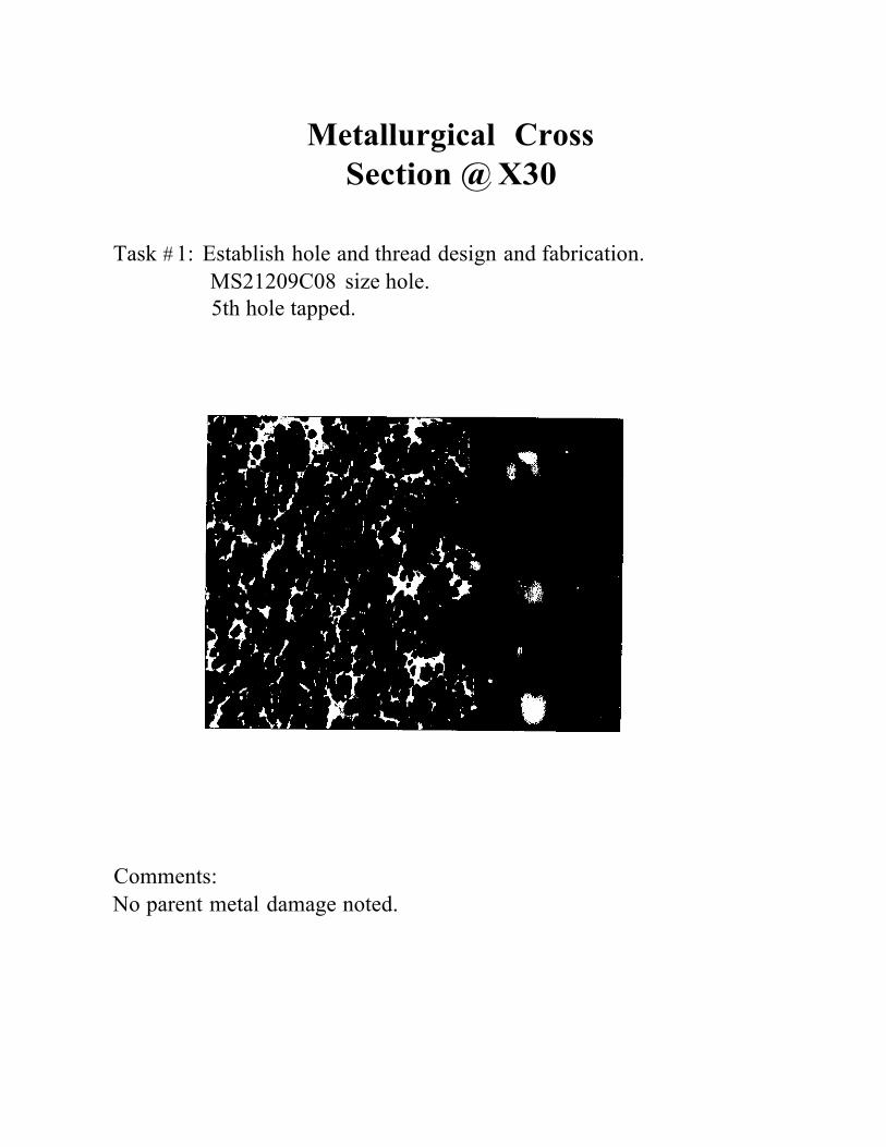
Task #1: Establish hole and thread design and fabrication.
MS21209C02 size hole. 5th hole tapped.
Comments: No parent metal damage noted.

Metallurgical Cross Section @ X30
Task# 1: Establish hole and thread design and fabrication. MS21209C04 size hole. 5th hole tapped.
Comments: No parent metal damage noted.
Metallurgical Cross Section @ X30
Task # 1: Establish hole and thread design and fabrication. MS21209C08 size hole. 5th hole tapped.
Comments: No parent metal damage noted.

Metallurgical Cross Section @ X30
Task #1: Establish hole and thread design and fabrication. MS21209C02 size hole. 20th hole tapped.
Comments: No parent metal damage or excessive tap wear noted.

Metallurgical Cross Section @ X30
Task # 1: Establish hole and thread design and fabrication.
MS21209C04 size hole. 20th hole tapped .
Comments: No parent metal damage or excessive tap wear noted.

Metallurgical Cross Section @ X30
Task # 1: Establish hole and thread design and fabrication.
MS21209C08 size hole. 20th hole tapped.
Comments: No parent metal damage or excessive tap wear noted.

Task #2: Verify insert length requirements for Beralcast™ 363
Objective:
Under this task we will determine the appropriate length for the helicoil inserts for the specified strength of the fasteners and sh'ear strength of the Beralcast™ 363. The fastener sizes requested are MS21209C0210L, MS21209C0410L, and MS21209C0810L. Our objective is to verify that the fasteners (bolts) will fail prior to the Beralcast™ 393.
Statement of work:
We will pull test three coupon each for insert lengths of 10, 1.50, and 20 for each size fastener listed above using the procedures established in task #1. After determining by pull test the appropriate length insert, we will prepare 3 coupons of this length for torque testing to failure for each size fastener. After testing to failure the inserts will be removed and new inserts will be re-installed. If thread repair or other operations are required, they will be so noted. (A procedure for field repair will be produced from this effort.)
Result:
Establish the appropriate length insert for each fastener size for a bolt tensile strength of 160,000 psi. (The purpose of Helicoil fasteners is to have the bolt break and not to strip the parent material. This is a function of the shear strength of the parent material, the ultimate tensile strength of the bolt, the length of the insert, and the condition of the tapped holes.)

Task #2: Verify insert length requirements for Beralcast® 363.
Results:
Tensile tests
Insert Length 1.0 D
MS21209C02
Bolts failed at 245
MS21209C04
Bolts failed at 645
MS21209C08
Beralcast® 363 to 262 lbs. to 700 lbs. failed at 1650, 1746, & 1720 lbs. 1.5 D
N/A
N/A
Bolts failed at 2000 to 2170 lbs.
2.0 D
N/A
N/A
N/A
Torque Tests (All are bolt failures in torque testing.)
Torque test trial MS21209C0210L MS21209C0410L MS21209C0815L
1 12.5 in-lbs. 25 in-lbs. 2 12.5 in-lbs. 30 in-lbs. 3 15 in-lbs. 25 in-lbs.
90 in-lbs. 90 in-lbs. 75 in-lbs.
Comments:
1. Torque testing numbers may have had some influence from bending.

• • •
" " "' ,.
"'-·"-·..
'" '"
Task #3: Evaluation matrix on the mechanical fastening of Beralcast™ 363
Objective:
Under this task we will perform the testing as outlined in the table below. The fastener sizes requested are MS21209C0210L (size #2) for for fastener group size A, MS21209C0410L (size #4) for for fastener group size B, and MS21209C0810L (size #8) for fastener group size D.
Statement of work:
We will perform the testing according to the table below. This is the same table as requested by NMI with the exception of the SEM fractographic evaluation. We will provide NMI with a failed pullout specimen for each temperature tested and group size fastener for your fractographic evaluation. We will be metallurgically evaluating the failed pullout specimens as shown below at x30.
Fut.ner Group A A A D D D
Size: SP""imnlot
Numboor '0 " " '"
Install and NDI Evaluate
Thermal Cyle per ,,. ,,. ,,. ,,. "A Note 1
Metallurgically
Evaluate Cast M.terlal Adjacent
to Insert.
:-
"' "' "' "' "' ,,.
Propou·ty Valut1l at:
-- -- ---·
Ambient ,,. ,,. WA
: Tcamp-e-r.t-u-re=
Metallurglcodly Evat...a.c ..t
M-lal Adjacent to Failed Insert.:
::CC=> = -NJA - -N/A . -NfA
' "' WA WA "' "' "'
------1- ---- -- ---f- ---------- - .. -1----- Ambillnt
T..,perature
-:---- :·-.,•·c-·- 1 WA
.:.._ 1 "'' 1 _--- - NIA- - -T::::- -.,.---- --NIA
+12iC WA "' WA "' "" "'

Note:
1. Thermal cycle testing will be done 5 times from -55°C to +125°C. It will be held at the low and high temperatures for not less than 5 minutes.
2. Metallurgical evaluation of the cast material adjacent to the failed inserts, will
be done at x30.
3. The test set-ups and approaches will be similar to those used for NASA.
Result:
Complete the matrix on the mechanical fastening of Beralcast™ 363. Tabulate the results achieved.

Task #3: Evaluation matrix on the mechanical fastening of Beralcast® 363.
Resl!lts:
MS21209C021OL Specimen lot number Ill
Number of samples
Thermal cycled
Pull at ambient temp.
Pull at -55°C
Pull at +125°C Specimen lot number
Number of samples
Thermal cycled
Pull at ambient temp.
Pull at -55°C
Pull at +125°C
9
N/A
256, 255 & 257 lbs. 273, 270, & 272 lbs.
245, 247, & 239 lbs.
MS21209C0410L 9
N/A
655, 631 & 642 lbs.
715, 693, & 750 lbs.
662, 642, & 650 lbs.
3 All
260, 258, & 252 lbs.
N/A
N/A
Ill
3
All
648, 690, & 645 lbs.
N/A
N/A

MS21209C0815L
Specimen lot number Ill
Number of samples 9 3
Thermal cycled N/A All
Pull at ambient temp. 2100, 2050 & 21051bs. 2075, 2040, & 1910 lbs.
Pull at -55°C 2055, 2035, & 21251bs. N/A
Pull at +125°C 2060, 1955, & 20051bs. N/A
Comments:
1. Metallurgical cross sections to follow according to the matrix and sow. Photographs at x30 enclosed.
2. The procedures used to install the inserts were those verified in the previous
tasks.
3. All tensile tests were performed on an lnstron.
4. The low temperature and high temperature test set-ups are shown in the sketches attached.

Metallurgical Cross Section @ X30
Task #3: Evaluation matrix on the mechanical fastening of Beralcast 363. MS21209C0210L size insert. Failed at ambient temperature.

Metallurgical Cross Section @ X30
Task #3: Evaluation matrix on the mechanical fastening of
Beralcast 363. MS21209C041 OL size insert. Failed at ambient temperature.

Metallurgical Cross Section @ X30
Task #3: Evaluation matrix on the mechanical fastening of Beralcast 363. MS21209C0815L size insert. Failed at ambient temperature.

Metallurgical Cross Section @ X30
Task #3: Evaluation matrix on the mechanical fastening of Beralcast 363. MS21209C0210L size insert. Failed at -55 C

Metallurgical Cross Section @ X30
Task #3: Evaluation matrix on the mechanical fastening of
Beralcast 363. MS21209C041 OL size insert. Failed at -55 C

Metallurgical Cross Section @ X30
Task #3: Evaluation matrix on the mechanical fastening of Beralcast
363. MS21209C0815L size insert. Failed at -55 C

Metallurgical Cross Section @ X30
Task #3: Evaluation matrix on the mechanical fastening of Beralcast
363. MS21209C0210L size insert. Failed at +125 C

Metallurgical Cross Section @ X30
Task #3: Evaluation matrix on the mechanical fastening of
Beralcast 363. MS21209C0410L size insert. Failed at+ 125 C

Metallurgical Cross Section @ X30
Task #3: Evaluation matrix on the mechanical fastening of Beralcast
363. MS21209C0815L size insert. Failed at +125 C
Metallurgical Cross Section @ X30
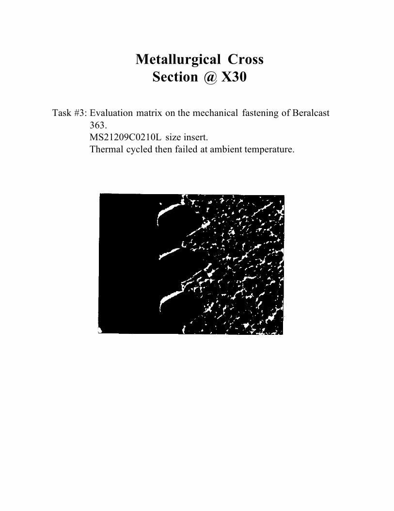
Task #3: Evaluation matrix on the mechanical fastening of Beralcast
363. MS21209C0210L size insert. Thermal cycled then failed at ambient temperature.

Metallurgical Cross Section @ X30
Task #3: Evaluation matrix on the mechanical fastening of Beralcast
363. MS21209C041 OL size insert. Thermal cycled then failed at ambient temperature.

Metallurgical Cross Section @ X30
Task #3: Evaluation matrix on the mechanical fastening of Beralcast 363. MS21209C0815L size insert. Thermal cycled then failed at ambient temperature.

Task #4: Salt fog coupons of Beralcast™ 363, Al6061 T6, and beryllium.
Objective:
To provide NMI with a set of salt fog coupons for testing utilizing the procedures established in tasks 1 through 3.
Statement of work:
Provide a set of coupons for NMI to test for each size fastener (Three in total, i.e. size A, B, & D.) A set of coupons will consist of two Beralcast™ 363, one Al6061 T6, and one beryllium. Each coupon will be 1" x 2" with 3 inserts installed per the procedures utilized in previous tasks. (Note: Two Beralcast™ 363 coupons are provided, one for testing and one for a control coupon for comparison. NMI may want to section one or both of these coupons after salt fog testing.)
Result:
Three sets of test coupons will be supplied to NMI for salt fog testing. (Please note, the coupons presently are not required to be coated.)

Task #5: Final report on the mechanical fastener (helicoil) effort for Beralcast™363
Objective:
Summarize and finalize the results from tasks 1 thru 3 on the mechanical fasteners (helicoils) tested on Beralcast™363.
Statement of work:
Prepare report summarizing the results from tasks 1 through 3. The following will be included for each fastener size.
1. A procedure that can be applied to production requirements for the drilling
and tapping of each size fastener tested. This procedure will specify drill diameters, tap sizes and insert lengths. Insert installation procedures will be discussed.
2. Field installation and replacement procedures for broken bolts.
3. Photographs ( at x30) with a review on tap life, parent material, and thermal
cycling effects.
A copy of all test results , compiled into a tabulated format for task #3 will be provided and then we will provide a discussion on each of the following topics.
A. Similarity of existing installation procedures to ours suggested in 1 above.
Along with the technical merits of this approach.
B. The impact of stress risers in the material, if any.
C. Cost impact associated with the use of Beralcast™363.
D. Technical merits.
1

E. Appearance.
F. Scrap generation.
G. Environmental Impact.
Result:
Five copies of our final report will be supplied to NMI.
2

MS21209C041 OL Installation Procedure
Oper. # Operation Tool Comment
1
Drill hole to a minimum depth of 0.318" or through
0.1200" diameter carbide tipped drill bit
None
2
Countersink 120° +/-5° to a diameter of 0.14 to 0.17"
120° countersink
None
3
Tap #4(0.112")-40 to a thread depth of 0.140"
04CPB plug style tap or equivalent
Class 3B fit. Brush on tapping fluid, see note a below.
4 Remove chips Use D.I. water Do not use air. Air will spread chips & possibly Be dust.
5
Check tapped hole
Use proper gage
None
6
Install MS21209C041OL to 0.75 to 1.5 pitch below surface.
Use installation tool 7551-04 or equivalent
None
7
Break off tang
Use tang break off tool number 3695-04 or equivalent
None
NOTES:
A. Use a soluble oil with a base of hydrotreated heavy naphthenic distillate (64742525) and Morphonine (002224444). We suggest a product called Rust-Lick WS-11 from ITW Fluid Products Group in St. Louis, MO. 63114, 800-443-9536 or equivalent.
B. Some part numbers above are from Helicoil. They are located in Danbury,
Connecticut, phone# 203-743-7651.

MS21209C021 OL Installation Procedure
Oper. # Operation Tool Comment
1
Drill hole to a minimum depth of 0.236" or through
0.0960" diameter carbide tipped drill bit
None
2
Countersink 120° +/-5° to a diameter of 0.09 to 0.11"
120° countersink
None
3
Tap #2(0.086")-56 to a thread depth of 0.100"
02CPB plug style tap or equivalent
Class 3B fit. Brush on tapping fluid, see note a below.
4 Remove chips Use D.I. water Do not use air. Air will spread chips & possibly Be dust.
5
Check tapped hole
Use proper gage
None
6
Install MS21209C0210L to 0.75 to 1.5 pitch below surface.
Use installation tool 551-02 or equivalent
None
7
Break off tang
Use tang break off tool number 3695-02 or equivalent
None
NOTES:
A. Use a soluble oil with a base of hydrotreated heavy naphthenic distillate (64742525) and Morphonine (002224444). We suggest a product called Rust-Lick WS-11 from ITW Fluid Products Group in St. Louis, MO. 63114, 800-443-9536 or equivalent.
B. Some part numbers above are from Helicoil. They are located in Danbury,
Connecticut, phone # 203-743-7651.

MS21209C0815L Installation Procedure
Oper. # Operation Tool Comment
1
Drill hole to a minimum depth of 0.516" or through
0. 1770" diameter carbide tipped drill bit
None
2
Countersink 120° +/-5° to a diameter of 0.20 to 0.23"
120° countersink
None
3
Tap #8(0.164")-32 to a thread depth of 0.280"
2C-·PB plug style tap or equivalent
Class 3B fit. Brush on tapping fluid, see note a below.
4 Remove chips Use D.I. water Do not use air. Air will spread chips & possibly Be dust.
5
Check tapped hole
Use proper gage
None
6
Install MS21209C0815L to 0.75 to 1.5 pitch below surface.
Use installation tool 7551-2 or equivalent
None
7
Break off tang
Use tang break off tool number 3695-2 or equivalent
None
NOTES:
A. Use a soluble oil with a base of hydrotreated heavy naphthenic distillate (64742525) and Morphonine (002224444). We suggest a product called Rust-Lick WS-11 from ITW Fluid Products Group in St. Louis, MO. 63114, 800-443-9536 or equivalent.
B. Some part numbers above are from Helicoil. They are located in Danbury,
Connecticut, phone# 203-743-7651.

Task #5: Final report on the mechanical fastener (helicoil) effort for Beralcast® 363.
Discussion:
A. Similarity of existing installation procedures to ours suggested (in 1 above) for Beralcast® 363. Along with the technical merits of this approach.
The procedures previously supplied are very similar to those used for aluminum with basically the following differences.
1.0 The use of carbide tipped drills versus high speed steel drills. 2.0 The use of larger diameter drills. 3.0 The use of specific lubricates for tapping to minimize reactions and
galling.
B. The impact of stress risers in the material, if any.
No stress risers were observed during the coarse of testing. Due to the scope of this effort we can not preclude the existence of stress risers or concentration that are more significant than other materials like aluminum.
C. Cost impact associated with the use of Beralcast® 363.
The installation of inserts into Beralcast® 363 can have the following three different areas of cost effects over aluminum.
1.0 Tooling. Through the testing performed, the life span for tooling on
Beralcast® 363 is 20 holes. Aluminum is estimated at 100 holes. Based on the price we paid for the taps, drills and fluids, we estimate a difference of $0.80 per hole for tooling.
2.0 Labor. On the installation of less than 50 inserts, we see no difference
in cost over aluminum. Larger quantities based on fixturing and part complexity may have a cost impact associated with Beralcast® 363. This would primarily be savings from seconds to possibly a couple of minutes.

3.0 Risk. The major impact would come from the higher cost associated
with the scrapping of a Beralcast® 363 part. This risk can be (or has been) minimized by first choosing a conservative life span for the tooling like we have suggested (i.e. 20 holes). Then the only the factor is operator error. This also can be minimized by making sure operators are properly trained in this area and that set-up parts are used when feasible.
D. Technical merits.
N/A
E. Appearance.
The Beralcast® 363 parts look very similar to aluminum. There is nothing unusual or effect to be mentioned from our testing.
F. Scrap generation.
Small amounts of chips will be generated during drilling and tapping. These chips should be collected and disposed of according to local standards and requirements.
G. Environmental Impact.
At any time Beralcast® 363 is being drilled or tapped dry, then proper ventilation and vacuum systems should be used. Please refer to the Beralcast® Material Safety Data Sheet for information.

Final Report on
Adhesive Bonding
Report prepared for: Nuclear Metals, Inc. 2229 Main Street Concord, MA 01742 Report Prepared by: The Peregrine Falcon Corporation 1051 Serpentine Lane Suite 100 Pleasanton, CA 94566

Task 2.1.1CIII: Adhesive Bonding
Summary
Beralcast® 363 can be readily bonded using epoxy or silicone based adhesives. Consistent shear strengths over 2500 psi can be obtained at ambient temperatures for epoxy adhesives. Silicone adhesives can provide over 500 psi in shear strength under similar conditions.
Objective The goal for this effort was to investigate the shear strength joining capabilities for selected epoxy and silicone based adhesives. The shear strength goal based on potential structural joining applications was to verify that a shear strength target of 1500 psi could be achieved.
Discussion Attached are the statements of work (SOW), identified as Phases 1 and 2 performed under this effort. Each statement of work is separated by a section divider with the results from that SOW included.
The following items are those which we feel should be highlighted or brought to your attention.
1. A primer is essential in achieving consistent high shear strength bonds on
Beralcast® 363. BR-127 and SS4004 was used for epoxy and silicone based adhesives respectively.
2. EA9394 can provide over 2500 psi in shear strength from -55° C to +90° C.
EA9394 surpasses the original objective of this effort. 3. The Hysol 0151 patch kit can provide over 600 psi of shear strength while
Elektroguard 2100 provides over 250 psi over this same temperature range of -55° C to +90° C.
4. Other epoxy based systems readily bond to Beralcast® 363 like EA9309.
Again the use of a primer is encouraged. 5. Based on the results of this study, there is no reason why complex structures
cannot be bonded together out of Beralcast® 363.
1

6. Surface finish has some impact on bond strength. Bond strength of epoxy based systems degrade on anodized surfaces compared to results achieved on primed machined surfaces. This effect reverses itself for silicone based systems.
Conclusion
Across the temperature range of -55° C to +90° C, EA9394 can provide a shear strength in excess of 2500 psi. Hysol 0151 patch kit and Elektroguard 2100 can provide over 600 psi and 250 psi respectively.
Report submitted by: Robert E. Hardesty
The Peregrine Falcon Corporation Please note that NMI is free to duplicate any part or all of this report as it sees fit.
2

Task 2.1.1CIII: Adhesive Bonding
Objective:
Establish the process necessary to bond Beralcast® 363 using the tube and socket arrangement on the struts as the objective of this activity. In order for this process to be declared successful we must achieve a bond shear strength of 1500 psi (TBC) at room temperature. Achieving this goal will establish a high probability of success for phase 2 which covers the testing needs for the matrices of Tables I-2.1.1A through 1-2.1.1 C including tube and socket joints. Please note that the results from phase 1 may change the bond joint configurations, test procedures or specimens as presently outlined by NMI and LMC.
Statement of work:
We will establish an engineering basis for the issues identified below for the bonding of Beralcast® 363. Where we have extensive experience in the bonding of beryllium, aluminum and aluminum-beryllium materials, we will be addressing these issues in the most cost effective way possible and to provide a high degree of confidence that satisfactoryresults of the test matrix of phase 2 can be achieved. In order to verify our methods and procedures for phase 1, we will be running comparison coupons based upon Hysol's EA 9309NA epoxy adhesive. We have been utilizing this system for over 15 years on beryllium, aluminum, and AI-Be alloys. It has consistently produced high shear strengths. Using this known system on Beralcast® 363, gives us a set of target values for our destructive test results. After verifying that high shear strengths can be achieved with EA 9309NA on Beralcast™ 363, additional testing will be performed as described below.
The following bonding parameters for the NMI/ LMC specified adhesives will be established by performing destructive testing on Beralcast™ using ASTM 01002 finger coupons. ( See Appendix A )
1. Unique bond area surface preparation I surface finish. (mechanical, chemical,
etc.). 2. Maximum surface exposure time allowable (elapsed time between cleaning
and application of adhesive). [Our proposal is based on verifying the industry standard for aluminum of 4 hours. We will not be developing a new standard for Beralcast® 363.]
3

3. Determination of requirements for primer for epoxy adhesives. [The silicone based adhesive already has a primer associated with it for use.]
4. Bonding methods required (including method(s) for bondline control). [Aimed
at the tube/socket joints, issues like too much epoxy, bondline, injection holes and etc.]
5. Deleted: Thermal extremes and thermal cycling effects. [From -55"C to
upper limit]
6. Destructive joint test and evaluation procedures. [Verify methods for phase 2)
7. Facilities and equipment required for joint assembly. [Elevated temperature
fixturing and curing concept for the strut hardware (tube/socket).)
8. Specific joint design for the Task 2.1.1Clll effort. (This is the designs for the double lap shear test coupons and tube/socket bond joint test coupons. NMI will supply Beralcast® 363 material for both types of coupons. On the tube and socket coupons, NMI will supply these net to shape with minimal material for finish machining of the tube and socket interface and the test fixture interface.)
NMI to supply sufficient material to produce the test specimens for this effort. Approximately 250; 0.040" x 0.500" x 1.000" Beralcast™ 363 coupons will be required from NMI.
The following bonding parameters will be addressed by referring to our current process technology, industry standards, and/or other sources as indicated.
A) Cleaning method(s) and sequence (including identification, specification and
control of solvents and or solutions). B) Bond area cleanliness and verification (i.e. water-break test or water drop
test). C) Drying procedures.
D) Cleaned and prepared joint handling restrictions.
E,) Repair procedures.
F) Joint NDI evaluation procedures and acceptance criteria.
G) Material traceability and control (including shelf life and specification control).
4

H) Technician training, special skills required and skill certification.
I) Adhesive preparation methods (i.e. working pot life, mixing ratio, thinning, etc.) [According to the manufacturerʼs instructions for EA 9394, 0151, and Electroguard 210.]
J) Environmental controls (i.e. temperature, humidity, atmosphere, pressure,
etc.). [According to the manufacturerʼs instructions for EA 9394, 0151, and Electroguard 210.]
K) Work area controls and restrictions. [According to the manufacturerʼs
instructions for EA 9394, 0151, and Electroguard 210.]
L) Waste product identification. [Dependent on local, state and federal requirements.]
M) Safety and hazardous material and disposal issues. [MSDS sheets,
telephone conversations, distributed reports and letters on E.H.& S.]
Result Provide a general process specification and guideline on the bonding of Beralcast® 363 using Hysol EA 9394, Hysol 0151, and Electroguard 2100. This will be accomplished by relying upon the specific information from destructive testing above. The test data will be provided in detail all other information will be referenced. These results will be discussed with NMI and a revised recommended test plan/matrix will be presented for phase 2 for approval.
5

Appendix A
Phase 1: ASTM 01002 bonding test coupons
Aluminum fingers
0.040" (Max) X 1.000" X 0.500' BeralcastT"' 363 shim between a set of ASTM D1002 coupons.
Proprietary

Results
6

Task 2.1.1CIII: Adhesive Bonding
Phase 1: Establish the general process for bonding Beralcast® 363.
Results
This effort investigated the parameters for the high strength bonding of Beralcast® 363. These parameters included surface finish, cleaning procedure, post clean exposure time, primers, adhesives, bond line thickness, and cure times and temperatures. Our objective was to achieve a bonding system with minimum shear strength of 1500 psi. The optimum parameters are identified below for each adhesive tested.
Parameter
EA9309NA
0151
EA9394
Elektroguard 2100
Surface finish
As machined or ground
As machined or ground
As machined or ground
As machined or ground
Cleaning procedure
H-F Nitric
H-F Nitric
H-F Nitric Solvent
Post clean exposure (Limit
to less than 4 hours)
Yes
Yes
Yes
No
Primer
BR-127
BR-127
BR-127
SS4004
Bond line thickness
0.005"
0.005"
0.005"
0.010"
Cure Adhesive at 1 hr@ 180°F
2 hr@ 140°F
1 hr@ 150°F
2hr@ 150°F
Average shear strength 4180 psi 4072 psi 3936 psi 571 psi
The three epoxy based adhesive systems investigated readily achieve our shear strength goals at ambient temperatures. The silicone based Elektroguard 2100 provided consistent results but not the high strength that the epoxy based systems provided. The following results and/or information was used in our efforts to verify a process for each adhesive system.
7

1. The EA9309 NA epoxy bonding system is one we typically use. We verified the cleaning processes, bondlines and primers versus this system to use as a reference base to compare the other epoxy and silicone adhesives against.
2. High shear strengths can be obtained on machined, ground and anodized
surfaces as long as proper cleaning methods are employed. Bare metal surfaces must be chemically etched.
3. Tests were run to bond to chem etched bare metal surfaces a full 4 hours
after cleaning. Shear test results were 25% below etched and primed surfaces.
4. Primer, if at all possible, provides a substantial increase in shear strength
results on both the epoxy and silicone based adhesive systems. Primer must be applied within the four hour limit after chem etching.
5. Numerous tests were run but the following bondline thickness provided the
best adhesive strengths for:
• EA9309NA • EA9394 • 0151 • Elektroguard 2100
0.005" 0.005" 0.005" 0.010"
6. All coupons were cleaned as follows, please note the difference method for
epoxy based adhesives and silicone based systems.
Operation Epoxy Silicone Clean machined or ground surface with
acetone acetone
Chern etch with H-F Nitric N/A
Rinse with D.l. water N/A
Dry with Kemwipes N/A
Oven dry at 200 °F for 15 minutes N/A
Prime and cure with BR-127 immediately SS4004 Immediately
8

Once the metal surfaces are primed, then the epoxy adhesives can be utilized up to 6 months thereafter and still achieve similar results. The silicone based adhesive should be applied within 24 hours after primer application. This silicone system has less data available and the primer/adhesive system lends itself easily to this timeframe for application. If longer timeframes are considered than additional testing should be performed.
7. Beralcast® 363 should be handled with clean powder free latex glove from
the point they are solvent wiped through etching, priming and bonding. The parts should be handled in relatively clean, dust free areas. Extreme care should be exercised to avoid the possible introduction of contamination into the adhesive or onto the prepared surfaces.
8. Anodized surfaces need only be solvent wiped prior to bonding directly to the
anodized coating. 9. All testing under this phase was done with ASTM 01002 single lap shear test
coupons. Please see the sketch attached on these type coupons. 10. A product data sheet is attached on each of the adhesives used under this
effort.


Task 2.1.1CIII: Adhesive Bonding
Objective:
Perform the bond test matrix according to tables I-2.1.1A through C. Please note that the results from phase 1 may change or influence this matrix.
Statement of work:
Perform the work identified in tables I-2.1.1A through C entitled "Adhesive Matrix" and "Adhesive Specimen Matrix" respectively less the fractographic I failure evaluation, micro metallurgical evaluation, and corrosion I salt fog testing. We will be supplying coupons for your evaluation for these deleted efforts. Substrate finishes (coatings) per table 1-2.1.1C need to be confirmed and are not part of our current proposal (i.e. anodization).
NMI to supply sufficient Beralcast® 363 material to produce the test specimens for this effort. Approximately x120 pieces of 0.060" x 1.000" x 4.000" will be needed for the double lap shear coupons, based on sandwiching the Beralcast™ 363 between two fingers of aluminum. We will also need approximately x16 tube and socket specimens. The tube and socket joint design will be defined in the phase 1 bond activity.
Result
Provide a report on the findings from our testing above and suggest ways to improve the general process specifications and guidelines provided under phase 1 for Beralcast® 363 for the temperatures and conditions tested. We will also provide all coupons as prepared for the test matrix, as tested and those requiring NMI to perform fractographic evaluation and salt fog testing. This report will also include any of our opinions and suggestions on the following topics.
1. Similarity to existing installation standards.
2. Reduction of stress risers in the design
3. Cost
4. Technical merits
5. Simplicity of procedures and practicality of production application.

6. Applicability of each technique to precision Beralcast® EOSS hardware.
7. Preparation required
8. Property or structure variation due to joint installation.
9. Ability to finish.
10.Appearance
11. Field installation and replacement
12.Waste generation and identification
13. Environmental impact
11

Results
12

Task 2.1.1CIII: Adhesive Bonding
Phase 2: Adhesive matrix for Beralcast® 363.
Results
EA9394 meets the initial high strength objective of this effort. Patch kit 0151 also meets the requirements except at elevated temperatures as demonstrated by the test results shown at 90°C. The silicone based adhesive provides consistent strength but does not generate high strengths. This adhesive has interesting properties because of its electrically resistive properties and potting capabilities.
Table 1-2.1.1 Adhesive Specimen Matrix
Test Specimen Number
Adhesive Finish Pre-test condition
Shear test result, in psi
E1MS-01.1
EA9394
Machined &
None
6200 Primed
E1MS-01.2
EA9394
Machined & Primed
None
7080
E1MS-01.3
EA9394
Machined & Primed
None
6380
E1MS-02.1
EA9394
Machined & Primed
Thermal cycled 10 times
7100
E1MS-02.2
EA9394
Machined & Primed
Thermal cycled 10 times
7600
E1MS-02.3
EA9394
Machined & Primed
Thermal cycled 10 times
6880
E1MS-03.1
EA9394
Machined & Primed
None
7000
13

E1MS-03.2 EA9394 Machined & None 7480 Primed
E1MS-03.3 EA9394 Machined &
Primed None 6800
E1MS-04.1
EA9394
Machined &
None
9420@ -55°C Primed •
E1MS-04.2
EA9394
Machined &
None
9300@ -55°C Primed
E1MS-04.3
EA9394
Machined &
None
8640@ -55°C Primed
E1MS-05.1
EA9394
Machined &
None
3400@ Primed +90°C
E1MS-05.2
EA9394
Machined &
None
2980@ Primed +90°C
E1MS-05.3
EA9394
Machined &
None
2800@ Primed +90°C
E1MS-06.1
EA9394
Machined & Primed
Thermal cycled 10
Salt Fog
times
E1MS-07.1
EA9394
Machined &
None
Salt Fog Primed
E1MS-07.2
EA9394
Machined &
None
Salt Fog Primed
E1MS-07.3
EA9394
Machined &
None
Salt Fog Primed
E1AS-01.1
EA9394
Machined & Anodized
None
5760
E1AS-01.2
EA9394
Machined &
None
5440 Anodized
14

E1AS-01.3 EA9394 Machined & None 5700 Anodized
E1AS-02.1 EA9394 Machined & Thermal 4760
Anodized cycled 10 times
E1AS-02.2 EA9394 Machined & Thermal 4240
Anodized cycled 10 times
E1AS-02.3 EA9394 Machined & Thermal 4400
Anodized cycled 10 times
E1AS-03.1 EA9394 Machined & None 5760
Anodized
E1AS-03.2 EA9394 Machined & Anodized
None 6180
E1AS-03.3
EA9394
Machined &
None
5580 Anodized E1AS-04.1
EA9394
Machined &
None
7400@ -55°C Anodized E1AS-04.2
EA9394
Machined & Anodized
None
7200@ -55°C
E1AS-04.3
EA9394
Machined &
None
6600@ -55°C Anodized E1AS-05.1
EA9394
Machined &
None
2672@ Anodized +90°C E1AS-05.2
EA9394
Machined & Anodized
None
2960@ +90°C
E1AS-05.3
EA9394
Machined & Anodized
None
2992@ +90°C
E1AS-010.1
EA9394
Machined &
None
Salt Fog Anodized
15

E2MS-01.1 0151 Machined & Primed
None 7240
E2MS-01.2
0151
Machined &
None
6760 Primed E2MS-01.3
0151
Machined &
None
6820 Primed E2MS-02.1
0151
Machined &
Thermal
5360 Primed cycled 10 times E2MS-02.2
0151
Machined &
Thermal
6040 Primed cycled 10 times E2MS-02.3
0151
Machined & Primed
Thermal cycled 10
4860
times E2MS-03.1
0151
Machined &
None
6980 Primed
E2MS-03.2
0151
Machined &
None
5760 Primed E2MS-03.3
0151
Machined &
None
7400 Primed
E2MS-04.1
0151
Machined &
None
5600@ -55°C Primed
E2MS-04.2
0151
Machined &
None
7300@ -55°C Primed E2MS-04.3
0151
Machined &
None
6700@ -55°C Primed E2MS-05.1
0151
Machined &
None
840@ +90°C Primed E2MS-05.2
0151
Machined &
None
912@ +90°C Primed
16

E2MS-05.3 0151 Machined & None 800@ +90°C Primed
E2MS-06.1 0151 Machined & Thermal Salt Fog Primed cycled 10 times
E2MS-07.1 0151 Machined & Primed
None Salt Fog
E2MS-07.2
0151
Machined &
None
Salt Fog Primed
E2MS-07.3
0151
Machined & Primed
None
Salt Fog
E2AS-01.1
0151
Machined & Anodized
None
5680
E2AS-01.2
0151
Machined & Anodized
None
6000
E2AS-01.3
0151
Machined &
None
5680 Anodized
E2AS-02.1
0151
Machined & Anodized
Thermal cycled 10 times
5320
E2AS-02.2
0151
Machined & Anodized
Thermal cycled 10 times
5640
E2AS-02.3
0151
Machined & Anodized
Thermal cycled 10 times
5060
E2AS-03.1
0151
Machined & Anodized
None
5960
E2AS-03.2
0151
Machined & Anodized
None
5960
17

E2AS-03.3 0151 Machined & Anodized
None 6000
E2AS-04.1
0151
Machined &
None
7456@ -55°C Anodized E2AS-04.2
0151
Machined &
None
6400@ -55°C Anodized E2AS-04.3
0151
Machined &
None
6200@ -55°C Anodized E2AS-05.1
0151
Machined &
None
BOO@ +90°C Anodized
E2AS-05.2
0151
Machined &
None
632@ +90°C Anodized E2AS-05.3
0151
Machined &
None
740@ +90°C Anodized E2AS-06.1
0151
Machined &
None
Salt Fog Anodized S1AS-01.1
Elektroguard
Machined &
None
N/A 2100 Anodized
S1AS-01.2
Elektroguard
Machined &
None
812 2100 Anodized
S1AS-01.3
Elektroguard
Machined &
None
760 2100 Anodized
S1AS-02.1
Elektroguard
Machined &
Thermal
656 2100 Anodized cycled 10 times S1AS-02.2
Elektroguard 2100
Machined & Anodized
Thermal cycled 10
724
times S1AS-02.3
Elektroguard
Machined &
Thermal
696 2100 Anodized cycled 10 times
18

S1AS-03.1 Elektroguard 2100
Machined & Anodized
None 745
S1AS-03.2
Elektroguard
Machined &
None
715 2100 Anodized S1AS-03.3
Elektroguard 2100
Machined & Anodized
None
735
S1AS-04.1
Elektroguard
Machined &
None
1072@ -55°C 2100 Anodized S1AS-04.2
Elektroguard
Machined &
None
1212@ -55°C 2100 Anodized S1AS-04.3
Elektroguard
Machined &
None
1288@ -55°C 2100 Anodized S1AS-05.1
Elektroguard
Machined &
None
270@ +90°C 2100 Anodized
S1AS-05.2
Elektroguard
Machined &
None
326@ +90°C 2100 Anodized S1AS-05.3
Elektroguard
Machined &
None
290@ +90°C 2100 Anodized
S1AS-06.1
Elektroguard
Machined &
None
Salt Fog 2100 Anodized S1MS-01.1
Elektroguard
Machined &
None
610 2100 Primed
S1MS-01.2
Elektroguard
Machined &
None
621 2100 Primed
S1MS-01.3
Elektroguard
Machined &
None
568 2100 Primed
19

Task 2.1.1Clll: Adhesive Bonding Additional Comments
A. Bonding procedures for Beralcast® 363 are similar in nature to other
metal bonding methods. Primer is typically used on all types of metals including aluminum and titanium. The use of a primer allows for the necessary time required for the bonding of any complex structure.
B. No significant cost impact was noted associated with comparing the
bonding process of Beralcast® 363 to other aerospace applications using metals like aluminum. The only issue associated with cost is the is risk. Since Beralcast® 363 components are typically more costly than aluminum; there will be an increase in the overall price of bonded Beralcast® assemblies to cover the potential loss of an assembly.
C. The methodology and approach to bonding Beralcast® assemblies
follows normal metal bonding procedures. D. Due to the cleaning procedures required to achieve high strength
bonds, bonding of Beralcast® for primary structural loads is not seen as a field operation. Patch and silicone bonds can be done in the field as long as surfaces are simply solvent wiped not abraded.
E. Significant waste generation is not foreseen in the bonding of Beralcast®.
The only potential area would be the etchant solution used for cleaning of the bond faying surfaces prior to the deposition of primer.

Final Report on the Mechanical Fasteners
(Press and shrink fit pins)
Report prepared for: Nuclear Metals, Inc. 2229 Main Street Concord, MA 01742 Report Prepared by: The Peregrine Falcon Corporation 1051 Serpentine Lane Suite 100 Pleasanton, CA 94566

1
Final Report on the Mechanical Fasteners (Press and Shrink Fit Pins)
Summary
Beralcast® 363 behaves more like aluminum than beryllium when a pin is installed using an interference fit. Over 136 pins were installed into Beralcast® 363 through press and shrink fits. None of these installations resulted in parent material damage to the Beralcast® 363.
Objective
This effort was a cursory study to investigate interference fits in Beralcast® 363 as they apply to pins. A general process specification for the installation of 0.190" and 0.375" diameter pins is provided. A discussion on similarities to A356 aluminum is also explored.
Discussion
Attached are the statements of work (SOW), identified as Phases 1,2 and 3 performed under this effort. Each statement of work is separated by a section divider with the results from that SOW included.
The following items are those which we feel should be highlighted or brought to your attention.
1. We had anticipated some brittle failures in installing press fits into Beralcast®
363. None were observed during the course of this testing even though some mis-alignment and severe interference fits were performed.
2. An effort was made to press fit pins into Beralcast® 363 to get the material to
fail by fracture. This was done by increasing the maximum tight interference fit by 50% (0.0015" to 0.0022"). After 10 coupons, no indications were present showing any cracks or defects.
3. Each 0.190" diameter pin was precision ground to -0.00000/+0.000040".
Each corresponding Beralcast® 363 coupon was ground to 0.200" -/+ 0.002" and an appropriate hole was reamed into place through the following steps.

2
Oper. #
Operation
Comments
1.0
Drill a hole using a carbide tipped 0.140" dia. drill
Starting hole diameter
2.0
Open the hole up by using a four fluted 0.184" dia. end mill.
uniformly open the hole up to the approximate diameter.
3.0
Ream the hole with a solid carbide reamer.
Cutting fluids will vary the final diameter due to cooling effects of a lubricant
4.0 Press pin into place using a controlled set-up.
Use a press or facility for the proper installation of pins.
3. Each 0.375" diameter pin was precision ground to -0.00000/+0.000040".
Each corresponding Beralcast® 363 coupon was ground to 0.340" -/+ 0.002" and an appropriate hole was reamed into place through the following steps.
Oper. #
Operation
Comments
1.0
Drill a hole using a carbide tipped 0.3125" dia. drill
Starting hole diameter
2.0
Open the hole up by using a four fluted 0.3715" dia. end mill.
Uniformly open the hole up to the approximate diameter.
3.0
Ream the hole with a solid carbide reamer.
Cutting fluids will vary the final diameter due to cooling effects of a lubricate.
4.0
Press pin into place using a controlled set-up.
Use a press or facility for the proper installation of pins.

3
4. An in depth investigation of the 0.190" diameter pins was performed per Table 1-2.1.2C: Pin Downselect Matrix. The comparative test results to aluminum A356 are as follows:
Type
Fit
Beralcast® 363, average install force in lbs.
Beralcast® 363, average test force in lbs.
Aluminum A356 average install force in lbs.
Aluminum A356 average test force in lbs.
Obi shear Light 413 2511 300 2256 Push
Light
413
143
330
214
Obi shear
Tight
590
2563
434
2100
Push
Tight
548
185
525
329
Double shear strengths on Beralcast® 363 exceed those of aluminum A356 while the push through force is lower. This lower number could be related to the difference in the elastic portion of deformation for A356 & Beralcast® 363. Deformation (Elongation) is made up of elastic and plastic portions. If the elastic portion of deformation of A356 is larger than Beralcast® 363, then the pin will need to overcome a higher initial force to start to push through. Further study would be needed to determine if this is the effect being demonstrated.
5. None of the push through I pull out coupons showed any signs of cracking.
6. The double shear coupons showed signs of initial ductility prior to failure by
fracture.
7. The conductive surfaces tested were Alodine per Mii-C-5541 and the Anodize surfaces were Mii-C-8625 Type Ill.
8. No appreciable differences were seen in double shear strength on
Beralcast® 363 from light to tight fits or from as machined surfaces to conductive or anodized surfaces.
9. Some differences were observed from light to tight and coating influences on
the push through force in Beralcast® 363. More data is required in order to establish any significance.

4
Conclusions Pins can readily be installed in Beralcast® 363 with interference fits of up to 0.00160". (This study tested pin interference fits on 0.190" and 0.375" diameter pins. Smaller than 0.190" and larger than 0.375" diameter pins should first be verified prior to use.)
Report submitted by:
Robert E. Hardesty The Peregrine Falcon Corporation
Please note that NMI is free to duplicate any part or all of this report as it sees fit.

5
Task 2.1.2CIII: Mechanical Fasteners Phase 1: Investigate the general process for the press and shrink fitting of
pins into BeralcastrM 363.
Objective:
Investigate the processes necessary to press and shrink fit pins into Beralcast™ 363 to exceed a push through (or pull out) strength of 250 lbs (TBC). Perform enough verification work to establish a high probability of success for the subsequent steps in accordance to the general intent of Tables 1-2.1.2 through 1- 2.1.2 D. Please note that this may change the pin, joint configurations or tolerances as presently outlined by NMI and LMC.
Statement of work:
Perform preliminary and verification work to address the following issues for the two sizes of pins identified by Lockheed Martin Corporation's "Table 1-2.1.2 Pin Matrix". We have divided the issues into three different sections. The first section will address its issues through destructive testing. The second section will address its issues based upon our experience, existing process specifications, and through the use of industry standards or other available technical information.
Prior to addressing the first set of issues, preliminary testing will be performed to verify the effects of pin installation into Beralcast™ 363. Our calculations show the potential for high stresses due to stress concentrations with interference fits like those shown in your table 1-2.1.2. Initial testing will be performed to establish guidelines for the maximum amount of interference that can be present before failure and the minimum that can be present to achieve the push through I pull out load requirement. 32 pins with press and shrink fits, 60 modified/knurled press fit pins and 12 wet press fit pins will be tested. Testing will include measuring push through forces (if the coupon survives installation).
This first section will address the following issues through destructive testing.
1. Installation condition (dry, wet) materials and process control.
a.) Wet installation shall use MMTI Specification 78002230 for application of
Locking compound per MIL R-46082, Type 1 and procedures for "loose" interference fits and; MMTI Specification 78002201, Type I for application

6
of MIL S-81733, Type 111-1 Polysulfide Sealant and procedures for other wet installations (reference 2.1.2 tables in Appendix 1).
2. Allowable Pin variation or modification (like knurling).
3. Installed pin condition or configuration.
4. Facilities and Equipment required for joint assembly.
5. Destructive joint test and evaluation procedures. (Particularly for tensile
pullout I push through and double shear.)
Under x30 magnification, cross sections of installed pins will be reviewed for process integrity.
NMI to supply sufficient material to produce the test specimens for this effort. This will be approximately x5 pieces of 0.650" x 3" x 8" and x5 pieces of 0.200" x 3" x 8" of Beralcast™ 363.
This second section will address the following issues based upon our experience, existing process specifications, and industry standards or other technical sources.
A) Deburring, cleaning and descaling (as required).
B) Hole evaluation and inspection procedures and acceptance criteria.
C) Pin installation methods.
D) Joint NDI evaluation procedures and acceptance criteria.
E) Thermal extremes and thermal cycle effects.
F) Repair or replacement procedures.
G) Environmental controls (i.e. temperature, humidity, atmosphere, pressure,
etc.).
H) Technician training, special skills required and skill certification. I) Hole sizes, position, configuration, and tolerance (in accordance with existing
industry installation specification or standards as guidelines). J) Hole and fastener tapers, chamfers, radii, etc.

7
Desirable Results
Provide a general process specification and guideline on press and shrink fitting of pins into Beralcast™ 363 relying upon the specific information from the testing above. The test data will be provided in detail all other information will be referenced. These results will be discussed with NMI and a revised recommended test plan/matrix will be presented for phase 2 for approval.

Results

Task 2.1.2CIII: Mechanical Fasteners Phase 1: Investigate the general process for the press and shrink fitting of
pins into BeralcastrM 363.
Results
Discussion:
Beryllium has been known to be a brittle material. Substantial interference fits typically are not successful. Beryllium does not readily yield to evenly distribute loads. Loads tend to concentrate at a singular point or location until it surpasses the yield strength and then rapidly reaches the ultimate strength at which time failure occurs. Due to Beralcasts' high beryllium content, it was assumed that it may also have some of these same difficulties. Interference fits (i.e. a pin in a hole) represent a high risk operation for these type materials. No matter how perfect a hole is reamed and a pin is made, this arrangement will always generate a high stress at a singular point.
Initial stress calculations for a pin in hole arrangement on BeralcastrM indicated we would start to exceed the specified yield strength of BeralcastrM once we exceed an interference of 0.0002" for the 0.190" diameter pins and 0.0004" for the 0.375" diameter pins. If BeralcastrM yields like beryllium, then more significant interference fits would lead to failures.
Extreme care was taken to control our overall approach to the testing of a pin and a hole arrangement on BeralcastrM_ Pins were produced like precision hole gages by grinding to within a tolerance of -0.00000 to + 40 millionths of an inch. Techniques we developed in order to produce holes consistently to the same diameter through a series of drilling, end milling and reaming operations. Reamers were produced to precision ground dimensions in order to achieve minor variations to hole diameters. Additional efforts were performed in order to provide a backu p position in case the interference fit approach became too sensitive to process variations in order to be successful. The backup approach that we had base lined was the knurling of the pins in order to produce a pin that is not consistently solid all the way around the outside diameter. This would allow room for material and pin to perform in an interference condition.
During these initial operations, where slight interference fits were being explored under this first phase effort, it became apparent that the BeralcastTM material was more ductile than our initial conservative thoughts. Our focus then changed to, within reason, what would it take to initiate a crack in the BeralcastTM material. We focused on the smaller diameter pins because our initial stress calculations

indicated that the smaller diameter pins generated the highest stress proportionately as interferences increased. Using the loose, light and tight allowances for interference from Lockheed Martin, we progressed to place a pin in an appropriate hole to demonstrate these fits and to verify our technique. We could not generate a crack in the Beralcast material by simple installation. Therefore, we focused on exceeding the tight interference fit by approximately 50%, and again could not get a crack to initiate in the material.
Coupon# Amount of
interference in
Installation force in lbs.
Push out force in lbs.
inches
77-1
0.0022
740
165
77-2
0.0023
870
280
77-3
0.0023
790
230
77-4
0.0022
760
240
77-5
0.0023
870
325
77-6
0.0022
880
335
77-7
0.0022
860
320
77-8*
0.0023
1000
405
77-9
0.0023
960
400
77-10
0.0022
1000
425
Average
0.0023
873
312 On Test 8 above, the pin was offset to the hole as we tried to install the pin. We deformed the hole, therefore we realigned and installed the pin. Even after this initial deformation to the hole, no cracks were apparent. This testing confirms that BeralcastTM is much more robust (under interference fits) than we had initially anticipated.
The BeralcastTM material utilized had a ground finish prior to a hole being placed into it. The pins utilized were 15-5PH CRES, condition H1025 with a 45° chamfer on the edge. Each hole was inspected using a precision ball gage with precision to 50 millions of an inch. Installation for the tests reported on above was performed by cooling the pins to oo C and heating the BeralcastrM material to

10
125° C (shrink fit). The two were then immediately brought together using a press setup. Each hole was inspected prior to and after under 30X magnification looking for defects. All testing was done at ambient temperature. The following operation steps are our guidelines for each pin size.
• Drill using a carbide tip drill, 0.140" dia. • Open hole with a four fluted end mill, 0.184" india. • Ream with a solid carbide reamer to the appropriate
diameter.

11
Task 2.1.2CIII: Mechanical Fasteners Phase 1: Investigate the general process for the press and shrink fitting of
pins into BeralcastTM 363. Additional Comments
Our overall approach to pin installation, followed guidelines used for aluminum and other materials. We suggest for reference purposes you can refer to ANSI 818.8.2-1978. All pins were clean and free from burrs and scale. The Beralcast® 363 was ground and then holes were reamed into place. Prior to installation each hole was inspected under magnification for defects. Each hole was measured for size to an accuracy of 0.000050". Pins were pressed into the Beralcast® 363 by utilizing an lnstron. This allowed us the ability to read the compressive load cell for installation force.

12
Task 2.1.2CIII: Mechanical Fasteners Phase 2: Pin 1 and 2 development matrix for BeralcastTM 363.
Objective:
After verifying the processes and testing procedures in phase 1, they will be applied to the test matrix of table I-2.1.2A and B to gain quantitative values and engineering data to make a pin downselect for table I-2.1.2C and D.
Statement of work:
Perform the work identified in table I-2.1.2A and B entitled "Pin 1: Development Matrix" and "Pin 2: Development Matrix" respectively less the fractographic I failure evaluation and micro metallurgical evaluations. We will be supplying coupons for your evaluation for this deleted effort.
NMI to supply sufficient material to produce the test specimens for this effort. The approximate material needs are x3 pieces of 0.650" x 3" x 8" and x3 pieces of 0.200" X 3" X 8".
Desirable Results
Provide the results from the testing above and in conjunction with NMI down select to one size pin for extensive testing according to table I-2.1.2C: "Pin Downselect Matrix". We will also provide all coupons as prepared for the test matrix, as tested and those requiring NMI to perform fractographic evaluation.

Results

Task 2.1.2CIII: Mechanical Fasteners Phase 2: Pin 1 and 2 development matrix for BeralcastTM 363.
Results: The specimens were created according to Table I-2.1.2A and B for the Pin 1 and 2 development matrix. Each hole was inspected visually and under magnification. No defects or indications were present. The following is the test data for these two matrices. All testing was done at ambient temperature.
Pin 1 (0.190) Development Matrix
Coupon #
p #
Interference type
Interference amount in
e/D
Installation force in lbs.
Push out force in lbs.
inches
P1-01.1 P1-01.2
1
3
Loose, Wet Press
Loose, Wet
0.00025
0.00020
1.0
1.0
160
185
115
144 Press P1-01.3 P1-02.1
5
2
Loose, Wet Press
Loose, Wet
0.00020
0.00025
1.0
1.5
145
140
105
102 P1-02.2
4
Press Loose, Wet
0.00020
1.5
158
88
P1-02.3
6
Press Loose, Wet
0.00020
1.5
145
115
P1-03.1
7
Press Light, Press
0.00040
1.0
N/A
160
P1-03.2
9
Light, Press
0.00035
1.0
278
95
P1-03.3
11
Light, Press
0.00035
1.0
270
188
P1-04.1
8
Light, Press
0.00035
1.5
440
248
P1-04.2
10
Light, Press
0.00035
1.5
392
124
P1-04.3
12
Light, Press
0.00035
1.5
368
210
P1-05.1
13
Tight, Press
0.00065
1.0
347
156

P1-05.2 15 Tight, Press 0.00065 1.0 368 218
P1-05.3
17
Tight, Press
0.00070
1.0
370
154
P1-06.1
14
Tight, Press
0.00065
1.5
516
172
P1-06.2
16
Tight, Press
0.00060
1.5
530
274
P1-06.3
18
Tight, Press
0.00060
1.5
480
174
P1-07.1
19
Tight, Shrink
0.00065
1.0
310
128
P1-07.2
21
Tight, Shrink
0.00065
1.0
362
78
P1-07.3
23
Tight, Shrink
0.00070
1.0
352
200
P1-08.1
20
Tight, Shrink
0.00060
1.5
455
144
P1-08.2
22
Tight, Shrink
0.00060
1.5
500
110 P1-08.3
24
Tight, Shrink
0.00065
1.5
608
316
Pin 2 (0.375) Development Matrix
Coupon #
p #
Interference type
Interference amount in
inches
e/D Installation force in lbs.
Push out force in lbs.
P2-01.1
1
Loose, Wet
0.00030
1.0
520
302 Press P2-01.2 3 Loose, Wet 0.00030 1.0 421 315 P2-01.3
5
Press Loose, Wet
0.00025
1.0
346
274
Press P2-02.1 2 Loose, Wet 0.00025 1.5 519 250
Press P2-02.2 4 Loose, Wet 0.00030 1.5 500 408
Press P2-02.3 6 Loose, Wet 0.00025 1.5 545 508
Press P2-03.1 7 Light, Press 0.00065 1.0 740 574
P2-03.2
9
Light, Press
0.00060
1.0
730
588 P2-03.3
11
Light, Press
0.00060
1.0
695
428

P2-04.1 8 Light, Press 0.00055 1.5 870 741
P2-04.2
10
Light, Press
0.00060
1.5
870
750
P2-04.3
12
Light, Press
0.00065
1.5
985
586
P2-05.1
1
Tight, Press
0.00165
1.0
1516
1188
P2-05.2
3
Tight, Press
0.00160
1.0
1636
1300
P2-05.3
5
Tight, Press
0.00160
1.0
1620
1262
P2-06.1
2
Tight, Press
0.00160
1.5
1700
1370
P2-06.2
4
Tight, Press
0.00165
1.5
1624
1330
P2-06.3
6
Tight, Press
0.00165
1.5
1900
1566
P2-07.1
7
Tight, Shrink
0.00160
1.0
1900
1125
P2-07.2
9
Tight, Shrink
0.00160
1.0
1860
1475
P2-07.3
11
Tight, Shrink
0.00160
1.0
1965
1425
P2-08.1
8
Tight, Shrink
0.00165
1.5
N/A
1710
P2-08.2
10
Tight, Shrink
0.00165
1.5
2060
1575
P2-08.3
12
Tight, Shrink
0.00170
1.5
2225
1720 At this point, a down select was to be made between further testing on the 0.190" diameter pins or the 0.375" diameter pins. However, the testing requested for the 0.375" diameter pins requires a nominal insertion length into the Beralcast™ material of 0.598". This thickness of material was unavailable for our further testing purposes and therefore, we selected the 0.190" diameter pin for additional testing as outlined in Table I-2.1.2C. Please also note, that the testing performed above with the 0.375" diameter pins was done with a Beralcast material of 0.340" in thickness.

Task 2.1.2CIII: Mechanical Fasteners Phase 3: Pin downselect matrix for Beralcast® 363.
Objective:
Perform a detailed evaluation of one size pin (as selected in phase 2) according to table I-2.1.2C and D.
Statement of work:
Perform the work identified in table I-2.1.2C and D entitled "Pin Downselect Matrix" and "Pin Specimen Matrix" respectively less the fractographic I failure evaluation, micro metallurgical evaluation and corrosion I salt fog testing. We will be supplying coupons for your evaluation for these deleted efforts. Surface finishes per table 1-2.1.2C need to be confirmed and are not part of our current proposal (i.e. anodization).
Under this effortwe will also test, evaluate and report on the specimens for:
1. NDI soundness of joint and freedom from defects caused by pin installation.
2. Defects (if any) in and around insert interface areas. (Please note that all our
evaluations will be done at x30 magnification. NMI will perform any fractography I SEM work.)
3. Mechanically tested for:
• Insertion loads • Pullout strength or push out loads • Double shear I bearing strength
4. At x30 magnification, evaluate the coupons for failure mechanism.
NMI to supply sufficient material to produce the test specimens for this effort. The approximate material needs will be x16 pieces of 3" x 8" of the thickness for the downselected pin diameter, plus x3 pieces of 3" x 8" of A356-AI-02 aluminum of the same thickness.

17
Desirable Results
Provide a report on the findings from our testing above and suggest optimal press or shrink fit designs and parameters for Beralcast™ 363 for the temperatures and conditions tested. We will also provide all coupons as prepared for the test matrix, as tested and those requiring NMI to perform fractographic evaluation and salt fog testing. This report will also include any of our opinions and suggestions we may have for the following topics.
1. Similarity to existing installation standards.
2. Reduction of stress risers in the material
3. Cost
4. Technical merits
5. Simplicity of procedures and practicality of production application.
6. Applicability of each technique to precision Beralcast™ EOSS hardware.
7. Hole design and preparation required
8. Property or structure variation due to joint installation.
9. Ability to finish joint area
10.Appearance
11. Field installation and replacement
12. Scrap generation and identification
13. Environmental impact

Results

Task 2.1.2CIII: Mechanical Fasteners Phase 3: Pin downselect matrix for Beralcast® 363.
Results
The specimens were created according to Table 1-2.1.2C: Pin Downselect Matrix. Each hole was inspected visually and under magnification. No defects or indications were present. The following test data was recorded. Please refer to the table for more specifics on each specimen.
0.190" Diameter Pin Light
Interference Fit with an e/D Ratio = 1.5
Specimen Surface Interference Installation Type Force in
# finish amount in inches
force in lbs. lbs.
PD-01-1.1 As mach 0.00060 418 Dbl Shear 2620
PD-01-1.2
As
mach
0.00060
402
Dbl Shear
2620
PD-01-1.3
As
mach
0.00055
412
Dbl Shear
2650
PD-01-2.1
As
mach
0.00055
394
Dbl Shear
2640
PD-01-2.2
As
mach
0.00060
411
Dbl Shear
2660
PD-01-2.3
As
mach
0.00055
416
Dbl Shear
2640
PD-01-3.1
As
mach
0.00055
375
Dbl Shear
2575
PD-01-3.2
As
mach
0.00055
438
Dbl Shear
2625
PD-01-3.3
As
mach
0.00055
372
Dbl Shear
2590
PD-01-4.1
As
mach
0.00055
437
Dbl Shear
2190
PD-01-4.2
As
mach
0.00060
448
Dbl Shear
2270
PD-01-4.3
As
mach
0.00060
492
Dbl Shear
2340
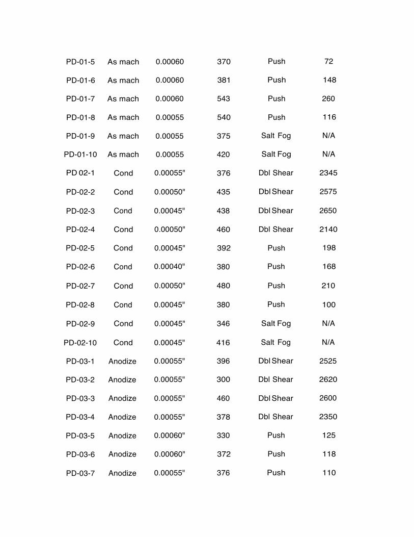
PD-01-5 As mach 0.00060 370 Push 72
PD-01-6
As mach
0.00060
381
Push
148
PD-01-7
As mach
0.00060
543
Push
260
PD-01-8
As mach
0.00055
540
Push
116
PD-01-9
As mach
0.00055
375
Salt Fog
N/A
PD-01-10
As mach
0.00055
420
Salt Fog
N/A
PD 02-1
Cond
0.00055"
376
Dbl Shear
2345 PD-02-2
Cond
0.00050"
435
Dbl Shear
2575
PD-02-3
Cond
0.00045"
438
Dbl Shear
2650
PD-02-4
Cond
0.00050"
460
Dbl Shear
2140
PD-02-5
Cond
0.00045"
392
Push
198
PD-02-6
Cond
0.00040"
380
Push
168
PD-02-7
Cond
0.00050"
480
Push
210 PD-02-8
Cond
0.00045"
380
Push
100
PD-02-9
Cond
0.00045"
346
Salt Fog
N/A
PD-02-10
Cond
0.00045"
416
Salt Fog
N/A
PD-03-1
Anodize
0.00055"
396
Dbl Shear
2525
PD-03-2
Anodize
0.00055"
300
Dbl Shear
2620
PD-03-3
Anodize
0.00055"
460
Dbl Shear
2600
PD-03-4
Anodize
0.00055"
378
Dbl Shear
2350
PD-03-5
Anodize
0.00060"
330
Push
125
PD-03-6
Anodize
0.00060"
372
Push
118 PD-03-7
Anodize
0.00055"
376
Push
110

20
PD-03-8 Anodize 0.00055" 416 Push 85
PD-03-9
Anodize
0.00055"
398
Salt Fog
N/A
PD-03-10
Anodize
0.00055"
394
Salt Fog
N/A
0.190" Diameter Pin Tight Interference
Fit with an e/D Ratio= 1.5
Specimen
# Surface finish
Interference amount in
Installation force in lbs.
Type Force in lbs.
inches
PD-04-1.1
As mach
0.00115
590
Dbl Shear
2505
PD-04-1.2
As mach
0.00120
565
Dbl Shear
2600
PD-04-1.3
As mach
0.00120
540
Dbl Shear
2600
PD-04-2.1
As mach
0.00120
600
Dbl Shear
2700
PD-04-2.2
As mach
0.00120
546
Dbl Shear
2770
PD-04-2.3
As mach
0.00110
575
Dbl Shear
2720
PD-04-3.1
As mach
0.00120
700
Dbl Shear
2700
PD-04-3.2
As mach
0.00120
615
Dbl Shear
2790
PD-04-3.3
As mach
0.00120
671
Dbl Shear
2800
PD-04-4.1
As mach
0.00120
523
Obi Shear
2360
P0-04-4.2
As mach
0.00115
680
Obi Shear
2180
P0-04-4.3
As mach
0.00125
558
Obi Shear
2225
P0-04-5
As mach
0.00110
515
Push
110
P0-04-6
As mach
0.00110
578
Push
226
P0-04-7
As mach
0.00115
698
Push
290

21
PD-04-8 As mach 0.00115 780 Push 234 PD-04-9
As mach
0.00105
475
Salt Fog
N/A
PD-04-10
As mach
0.00105
558
Salt Fog
N/A PD-05-1
Cond
0.00115"
538
Dbl Shear
2510 PD-05-2
Cond
0.00105"
590
Dbl Shear
2580 PD-05-3
Cond
0.00105"
602
Dbl Shear
2600
PD-05-4
Cond
0.00120"
632
Dbl Shear
2390
PD-05-5
Cond
0.00110"
492
Push
198
PD-05-6
Cond
0.00105"
472
Push
186 PD-05-7
Cond
0.00110"
638
Push
241 PD-05-8
Cond
0.00110"
498
Push
86 PD-05-9
Cond
0.00045"
474
Salt Fog
N/A PD-05-10
Cond
0.00045"
430
Salt Fog
N/A PD-06-1
Anodize
0.00120"
638
Dbl Shear
2550 PD-06-2
Anodize
0.00125"
445
Dbl Shear
2660 PD-06-3
Anodize
0.00125"
642
Dbl Shear
2620 PD-06-4
Anodize
0.00120"
552
Dbl Shear
2405 PD-06-5
Anodize
0.00120"
430
Push
193
PD-06-6
Anodize
0.00120"
462
Push
152 PD-06-7
Anodize
0.00125"
512
Push
163 PD-06-8
Anodize
0.00120"
502
Push
140
PD-06-9
Anodize
0.00115
632
Salt Fog
N/A
PD-06-10
Anodize
0.00120"
778
Salt Fog
N/A

22
Aluminum A356 0.190" Diameter Pin Light Interference Fit with an e/D Ratio = 1.5
Specimen #
Surface finish
Interference amount in
Installation force in lbs.
Type Force in lbs.
inches
Al-01-1
As mach
0.00050
330
Obi Shear
N/A
Al-01-2
As mach
0.00055
280
Obi Shear
2225
Al-01-3
As mach
0.00055
266
Obi Shear
2165
Al-01-4
As mach
0.00045
320
Obi Shear
2380
Al-01-5
As mach
0.00050
300
Push
65
Al-01-6
As mach
0.00040
325
Push
138
Al-01-7
As mach
0.00045
375
Push
300
Al-01-8
As mach
0.00045
318
Push
352 Al-01-9
As mach
0.00055
300
Salt Fog
N/A
Al-01-10
As mach
0.00050
300
Salt Fog
N/A

23
Aluminum A356 0.190" Diameter Pin
Tight Interference Fit with an e/D Ratio = 1.5
Specimen #
Surface finish
Interference amount in inches
Installation force in lbs.
Type Force in lbs.
Al-02-1
As mach
0.00100
390
Dbl Shear
1950
Al-02-2
As mach
0.00100
390
Dbl Shear
2150
Al-02-3
As mach
0.00110
484
Dbl Shear
2200
Al-02-4
As mach
0.00110
472
Dbl Shear
2100
Al-02-5
As mach
0.00100
485
Push
150
Al-02-6
As mach
0.00105
550
Push
242
Al-02-7
As mach
0.00105
541
Push
308
Al-02-8
As mach
0.00100
521
Push
615
Al-02-9
As mach
0.00105
485
Salt Fog
N/A
Al-02-10
As mach
0.00105
495
Salt Fog
N/A

24
Task 2.1.2CIII: Mechanical Fasteners
Phase 1: Investigate the general process for the press and shrink fitting of pins into BeralcastTM 363.
Additional Comments
We have the following observations and opinions.
1. Stress risers: We observed no unusual or brittle effects from stress risers on
Beralcast® 363 material in comparison to aluminum A356. 2. Cost: No appreciable cost impact over aluminum A356 installation was
noted. Please note, that Beralcast® 363 is a high performance material and the applications using this material will more critical and more involved than lower tachnology applications. Therefore, more NDE or inspection may be reqiured which will add more time to pin installation.
3. Hole design and preparation: Care should be utilized in opening up the hole
in Beralcast® 363 for pin installation. It discussed previously, in order to get as uniform a hole as possible, the hole should first be drilled undersize, then a four fluted end used to open up the hole, and then it should be reamed to size.
4. Field installation and replacement: We suggest if a pin needs to be re
inserted in the field that it is done so using a potting/adhesive compound. Upon initial installation in production the Beralcast® 363 will yield and through this process open up the hole. If the pin is removed in the field, we recommend potting it back into place. We would suggest that if the design requires, the part be returned to a facility set-up to handle Beralcast® 363 where a larger size hole could be reamed into place and an appropriate pin installed. Reaming Beralcast® 363 will release small paticles of beryllium into the air. This will require proper ventilation/handling. Please refer to the MSDS sheet.
5. Environmental impact: From our opinion, we do not foresee any
environmental impact from the installation of a pin into Beralcast® 363, outside of installation where proper ventilation should be used and making sure the product is protected from corrosion effects.

25
Reference Sheet of
Cross Section Samples Provided
PD Number Sample Number
PD Number Sample Number
PD-01-1.1
82-7
AL-01-2
84-1 PD-01-2.1 82-1 AL-01-6 84-8 PD-01-2.2 82-2 AL-02-1 85-3
PD-01-3.3
82-6
AL-02-2
85-1 PD-01-4.3 82A-12 AL-02-3 85-2 PD-01-5 82-13 AL-02-4 85-4
PD-02-3
86-4
AL-02-6
85-8 PD-02-7 86A-16 AL-02-8 85-10 PD-03-3 87-4 PD-03-4
87A-14
PD-03-6 87-8 PD-04-1.2 83-8
PD-04-2.1
83-1
PD-04-2.2 83-2 PD-04-3.1 83-4
PD-04-4.3
83A-12 PD-04-7 83A-17 PD-05-1 86A-11
PD-05-2
86-1
PD-05-4 86A-13 PD-05-5 86-5
PD-06-1 PD-06-2
87A-11 87-1
PD-06-5 87-5

These aluminum A356 coupons were used to compare to Beralcast 363
Metallurgical Cross Section
Phase 3: Pin downselect matrix for Beralcast 363.
Typical damage seen in Aluminum A356 coupons.
Comments:

These aluminum A356 coupons were used to compare to Beralcast 363
Metallurgical Cross Section @ X30
Phase 3: Pin downselect matrix for Beralcast 363.
Typical damage seen in Aluminum A356 coupons.
Comments:

These aluminum A356 coupons were used to compare to Beralcast 363
Metallurgical Cross Section @ X30
Phase 3: Pin downselect matrix for Beralcast 363.
Typical damage seen in Aluminum A356 coupons.
Comments:
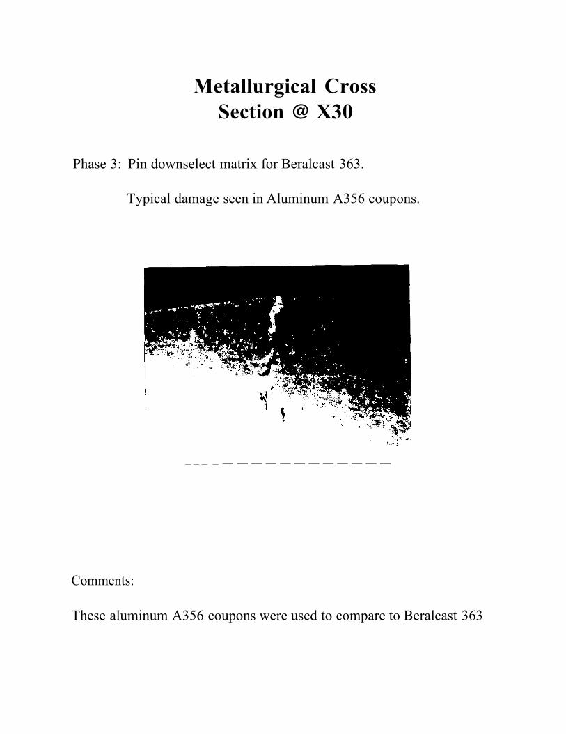
Comments:
These aluminum A356 coupons were used to compare to Beralcast 363
Metallurgical Cross Section @ X30
Phase 3: Pin downselect matrix for Beralcast 363.
Typical damage seen in Aluminum A356 coupons.
--- - ------------

Comments:
These aluminum A356 coupons were used to compare to Beralcast 363
Metallurgical Cross Section @ X30 Phase 3: Pin downselect matrix for Beralcast 363.
Typical damage seen in Aluminum A356 coupons.

Comments:
No unusual effects observed when compared to aluminum A356.
Metallurgical Cross Section @ X30
Phase 3: Pin downselect matrix for Beralcast 363.
Typical damage seen in Beralcast 363 in double shear failure

Comments:
No unusual effects observed when compared to aluminum A356.
Metallurgical Cross Section @ X30
Phase 3: Pin downselect matrix for Beralcast 363.
Typical damage seen in Beralcast 363 in double shear failure

Comments:
No unusual effects observed when compared to aluminum A356.
Metallurgical Cross Section @ X30
Phase 3: Pin downselect matrix for Beralcast 363.
Typical damage seen in Beralcast 363 in double shear failure
Comments:
No unusual effects observed when compared to aluminum A356.
Metallurgical Cross Section @ X30
Phase 3: Pin downselect matrix for Beralcast 363.
Typical damage seen in Beralcast 363 in double shear failure

Comments:
No unusual effects observed when compared to aluminum A356.
Metallurgical Cross Section @ X30
Phase 3: Pin downselect matrix for Beralcast 363.
Typical damage seen in Beralcast 363 in double shear failure

Comments:
No unusual effects observed when compared to aluminum A356.
Metallurgical Cross Section @ X30
Phase 3: Pin downselect matrix for Beralcast 363.
Typical deformation seen in Beralcast 363 from pin installation.

Comments:
No unusual effects observed when compared to aluminum A356.
Metallurgical Cross Section @ X30
Phase 3: Pin downselect matrix for Beralcast 363.
Typical deformation seen in Beralcast 363 from pin installation.