final report of product
DESCRIPTION
This is the final report of test board for stepper motor.TRANSCRIPT

KE30602 Design Project
Final Report
Project Title
Test board for stepper motor
Project Team Name
Touch The Sky
Client :Mr. Tee Tze We
Lecturer :Mr. Liau Chung Fan
Project Team Members:
1. Goai Teck Liang (HK2006-3572) 2. Wong Jih Kian (HK2006-5159) 3. Siti Nor Nabilah (HK2006-2096) 4. Tamil Selvam (HK2006-4025) 5. Mohd Faizal (HK2006-6601)

Acknowledgement
All graces belong to the Almighty alone. Without His grace and blessing, this project
would not have succeeded achieving the objective of the project. We would like to take
this opportunity to express our sincere gratitude to all those who have contributed in
completing this project. Firstly, our sincere thanks goes to our project design’s client
Mr. Tee Zee Wei for his professional ideas and constant attention throughout the
project design . It has been a privilege to work under him as our client .
We also appreciate the efforts and numerous suggestions of Mr. Liau Chung
Fan, to improve the performance of the project. We would like to extend our sincere
appreciation to the ROBOCON team for lending us to use the laboratory and for helped
us to further our step in doing this project by providing facilities and technical help
throughout the project.
Our special thanks go to the Administration of School of Engineering and
Information Technology , for providing this wonderful opportunity to carry out this
project design subject . The project has exposed us to the current technology and also
to increases our knowledge and skills in hardware implementation. We were also
exposed to do a proper research in order to get a clear idea on the selected topic.
Finally, our sincere thank to our friends for their support and motivation throughout
the completion of this project. Please feel free to write or send me e-mail to us

Executive summary
Our product is Test Board for Stepper Motor. The main purpose of designing this
product is for educational kit for a university student. However to make the learning
process more interesting, we design the test board for the stepper motor in the form of
car control. The main component of this product is stepper motor, PIC microcontroller,
encoder and LCD (liquid crystal display). Moreover to control the car control we are
using wireless remote by radio frequency.
The car is built with three wheels. For this product we only used one stepper
motor and it only control one wheel of the car and the other two wheels is used to
stabilize the car. It means that our car only can run forward and backward. Since our
purpose of design this project is for educational kit, we ignore the car control problems
to turn left or right.
In technically, we are design circuit by referring to the books, internet and also
by our own idea. Then we are using Proteus 7 professional to design the complete
circuit. Moreover to interface PIC with the stepper motor and LCD, we are using C
programming. The complete program is simulated in the MPLAB IDE v8.10 and it is
transfer to the PIC using PICkit V2.55 program.
There are many experiments we are doing in a process of building this product.
We are dividing our product into several technical parts such as encoder, LCD, speed
control, remote control and also radio frequency. Each of the part is experimented
separately and any changing will be done due to the time.
The stepper motor will be control by a remote control using radio frequency. The
input will be send directly to the microcontroller and microcontroller will send the data
to the motor drive. Therefore the motor drive will drive the motor. The output of the

motor will be send to the encoder to calculate the speed and from the encoder, the
speed will display to the LCD to display the output.
However there are many difficulties occur while doing the experiment for this
product. From the experiment we already done, we have to cancel some part in our
product. We found that we cannot use radio frequency to interface remote control with
the stepper motor. This is because there are some problem occurs while test our radio
frequency. Radio frequency has a problem to receive a data if in the same range of our
place there a same frequency is used. Noise from surrounding really can affect data
transferring. Therefore it will lag the time for the product to functioning.
Beside radio frequency, we also have to cancel our encoder part. This is because
we broke our encoder while test this part. Moreover it is hard to program the encoder.
Therefore we decide to cancel this part and find other solution to replace it.
As a solution for our failure in our process making this product, we replace the
part we already cancel with other method. For the problem of our radio frequency we
replace it with wire. We interface our remote control and stepper motor with a wire.
Therefore there no more wireless remote control. The main purpose we are changing
this part to wire is our product is about to test the stepper motor and if we get a
problem to send an input to the stepper motor, our product will totally fail. So by using
wire the input can be send to the stepper motor without any problem. Even this method
is not high technology, but we have to realize that it is more important to make the
stepper motor working and we have to ignore the wireless.
In addition of the solution, we replace the encoder with the PIC. Since the
function of the encoder is to calculate the speed of the stepper motor and the output
the data to display on the LCD screen, we decide to use PIC to calculate the speed.
Therefore we write C program to the PIC to calculate the data. In this case we produce
one formula to calculate the speed and put it to the program. So, the output of the
stepper motor will be calculated at PIC and send straightly to the LCD to display.

In conclusion of our finding in our process of making our product, we are really
recommended that this project to take an additional research for future because with
an additional research, this product could be improve and the quality can be increases.
List of figures
List of figures according to chapters Page
CHAPTER 1
Figure 1.1 : Cross section of unipolar stepper motor……………………………….………… 2
Figure 1.2: Cross section of bipolar motor………………………………………………………… 2
Figure 1.3 :Cross sectional of the motor parallel to the shaft……………………………… 3
CHAPTER 3
Figure 3.1:Schematic diagram of the complete design circuit…………………………… 14
Figure 3.2:Car body structure using aluminium ……………………………………………….15
Figure 3.3 :Car body structure using plastics………………………...…………………………15
Figure 3.4: Design of PCB layout using Proteus ( Circuit inside the remote control)…………………………………………………………………………………………………….….17
Figure 3.5 : Design of PCB layout using Proteus ( Circuit inside the racing car)……………………………………………………………………………………………………..……...17
Figure 3.6 : Pin connection of L298……………………….……………………………………….18
Figure 3.7 : Simple circuit of freewheeling diode……………………………..………………19
Figure 3.8 : Location of Dual Full Bridge and Free Wheeling Diode in the motor driver……………………………………………………………………………………………………….....19
Figure 3.9 : Full step stepper motor revolution……………………………………………..….20
Figure 3.10: Half stepping stepper motor revolution degree……………………………..20
Figure 3.11 : Output motor waveform…………………………………………………….….…..22

Figure 3.12 : Output waveform for microstepping circuit using oscilloscope…………………..24
Figure 3.13 : Structure of H- bridge (highlighted in red)…………………………..……..22
CHAPTER 4
Figure 4.1a: Failure circuit of LCD screen……………………………………………….………27
Figure 4.1b: Successful circuit of LCD screen………………………………………….……...27
Figure 4.2: Diagram circuit of voltage regulator………………………………………..…...28
Figure 4.4.1: RF Transmitter Module (433MHz)………………………………………..…...30
Figure 4.4.2: RF Receiver Module (433MHz)…………………………………………….……31
Figure 4.4.4: Circuit diagram of transmitter…………………………………………………..33
Figure 4.4.5: Shows the circuit of the receiver………………………………………………34
Figure 4.4.6: Representation of Each Bit in TXSTA Register………………………………37
Figure 4.4.7: Setting of the Register for USART……………………………………..……….37
Figure 4.4.8: Signal Transfer in Asynchronous mode………………………………………..38
Figure 4.4.9: Block Diagram Showing the transmitter’s program runs………………..39
Figure 4.4.10 Representation of Each Bit in RCSTA Register……………………..………40
Figure 4.4.11 Source codes detecting and solving overrun error…………………………41
Figure 4.6.1: Output waveform for 175 bit……………………………………………………..45
Figure 4.6.2: Output waveform for 53 bit…………………………………………………………46

List of Table
List of figures according to chapters Page
CHAPTER 2
Table 2.1 : Flowchart of the project………………………………………. ………..…………..8
Table 2.2: Estimation budget…………………………………………………………….…….…..11
CHAPTER 3
Table 3.1 : Analysis result of the H – bridge circuit………………………………..………23
CHAPTER 4
Table 4.1 : Test result of LCD screen…………………………………………………………..26
Table 4.2 : Result of Binary code according to the output voltage…………………..29
Table 4.4.1 : Specification of RF- Transmitter Module……………………………………30
Table 4.4.2 : Specification of RF-Receiver Module…………………..…………………….32
Table 4.4.3 : Show the specification of PIC16F877A ……….…………………………….32
Table 4.4.4: Register and Description which will be used……….………………………35
Table 4.5a: Car test data on flat surface(unipolar)………………………………………..43
Table 4.5b : Car test data on sliding surface(unipolar)…………………………………..43
Table 4.5c : Test result in different slant surface…………………………………………..44
Table 4.6: Data result of frequencies versus bits……………………………………..……47
Table 4.7a : Shows the result of the movement of the car at flat road.……………48
Table 4.7b : Shows the car movement result when run up the 300 hill……………49

Chapter 1
INTRODUCTION
1.1 Background
Stepper motor filled a unique niche in the motor control world. These motors
are mainly used in measurement and control applications. Sample applications include
ink jet printers, CNC machines and volumetric pumps. Several features common to all
stepper motors make them ideally suitable for these types of applications. Stepper
motors are brushless. The commutator and brushes of conventional motor are some of
the most failure prone components and they create electrical arcs that are undesirable
or dangerous in some environments. Stepper motor also will not turn at a speed
regardless of a load as long as the load does not exceed the torque rating of the motor.
Open loop position of stepper motors move in quantified increments of steps. Holding
torque characteristic is able to hold the shaft stationary. Stepper Motors come in a
variety of sizes, and strengths, from tiny floppy disk motors, to huge machinery
steppers. There are two basic types of stepper motors, bipolar and unipolar. The
unipolar stepper has 4 wires. Bipolar steppers have 5,6 or 8 wires.
Unipolar Stepper motor has 2 coils, simple lengths of wound wire. The coils are
identical and are not electrically connected. Each coil has a center tap - a wire coming
out from the coil that is midway in length between its two terminals. If the terminals of
a coil are connected, the shaft becomes harder to turn. Because of the long length of
the wound wire, it has a significant resistance (and inductance). The resistance from a
terminal to the center tap is half the resistance from the two terminals of a coil. Coil
resistance of half a coil is usually stamped on the motor. Figure 1.1 shows the cross
section of a stepper unipolar motor. Motor winding number 1 is distributed between the
top and bottom of stator poles, while motor winding 2 of stepper motor is distributed

between left and right of the stator poles. The rotor is permanent magnet with six
poles, three north and three south.
Figure 1.1 : Cross section of unipolar stepper motor.
The Bipolar Stepper motor is very similar to the unipolar Stepper except that the
motor coils lack center taps. Because of this, the Bipolar motor requires a different
type of controller, one that reverses the current flow through the coils by alternating
polarity of the terminals. The advantage to not having a center taps is that the current
runs through entire windings at a time instead just half the windings. As a result bipolar
motor produce more torque that unipolar motor. The draw back of bipolar motors, that
more complex control circuitry is required by bipolar motor. Current flow in bipolar
motor is bidirectional. This requires changing of polarity of each end of the windings. A
control circuit known as H-bridge is used to change the polarity on the end of the
windings.
Figure 1.2: Cross section of bipolar motor.
Figure1.2 illustrates bipolar stepper motor. Motor winding number 1 is distributed
between the top and bottom of stator poles, while motor winding 2 of stepper motor is

distributed between left and right of the stator poles. The rotor is permanent magnet
with six poles, three north and three south arranged around the circumference.
A stepper motor is a polyphase AC synchronous motor , and it is ideally driven by
sinusoidal current. A full step waveform is a gross approximation of a sinusoid, and is
the reason why the motor exhibits so much vibration. Various drive techniques have
been developed to better approximate a sinusoidal drive waveform which are half
stepping and microstepping.
When half stepping, the drive alternates between two phases on and a single
phase on. This increases the angular resolution, but the motor also has less torque at
the half step position. This mitigated by increasing the current in the active winding to
compensate. The advantage of half stepping is that the drive electronics need not
change to support it.
Microstepping is actual "sine cosine microstepping" in which the winding current
approximates a sinusoidal AC waveform. Regardless of the waveform used, as the
microsteps become smaller, motor operation becomes smoother. However, the purpose
of microstepping is not usually to achieve smoothness of motion, but to achieve higher
position resolution. Step size repeatability is an important step motor feature and a
fundamental reason for their use in positioning. Microstepping can affect the step size
repeatability of the motor.
Figure 1.3 :Cross sectional of the motor parallel to the shaft

1.2 Scope of the Project
The conceptual design is used as education kit for technical college especially for
engineering courses to educate them about stepper motor by applying in remote
control car. Basically it can apply to applied mechanic technical lab kit which can
calculate the speed motion of remote car controller. The racing car can control the
speed and show the speed value in the same time. For this design, the remote control
work as test board for control decided speed value and the LCD display showing the
control car moving speed. In this project, three different types of motors that are
bipolar stepper motor, unipolar stepper motor and DC motor. The main reason to use
different motors is to differentiate the functionality of each motor.
1.3 Objective
The objective of the project can be expressed from two prospects; they are from
project prospect and the individual prospect.
The objective of the project from the prospect of the project itself is to develop a
remote control car by using stepper motor. The development process covers the
designing process, fabrication and testing of the whole car controller and speed display
circuit. The designing process is the mechanical designing of the car structure and the
designing of the car speed controller and speed display circuitry. The fabricated
mechanical design will be tested to proof the performance level of the stepper motor.
From the individual prospect, the objective of the project is to improve the
designing, planning and analytical skills in examining the performance and relevance of
an idea from the scope of engineering field. On the other hand, throughout this project,
we gain valuable experience in designing a new product and would also gain deeper
understanding in microcontroller interfacing.

1.4 Problems with current method and new approach.
The educational kit with current method is only testing the speed of stepper
motor. Actually there are many advantages of stepper motor compared to the DC
motor. In the design, we are specifically testing the speed of stepper motor and the
grip braking of stepper motor. Steppers have very good holding torque. Steppers are
can hold a position (to a lesser degree) without power applied, using magnetic 'detent'
torque. Furthermore, we also included the test to differentiate between bipolar and
unipolar motor. Current method also not sufficient to the students as it is hard to
handle and not attractive.
New approach that we implemented in our design is testing the holding torque of
stepper motor. We built three different cars which are using bipolar, unipolar and DC
motor and tested simultaneously to differentiate the characteristic of holding torque of
each motor. To make our design attractive, we implemented the motors in racing cars.

Chapter 2
EXPLORING THE SOLUTION SPACE AND SELECTING SPECIFIC
APPROACH
2.1 Specific approach
The primary or main function of this project is to do a test board for the stepper
motor. The test board for the stepper motor should be able to control the speed of
stepper motor and display the speed. The new approach that we introduced in the
design is the stepper motor used is implemented in the racing car. The racing car
used as educational kit mainly for engineering students. Furthermore, we built two
sets of racing car which is using bipolar and unipolar motor to see the differences
between these two motors.
In our proposed design, we used stepper motor is to compare the stepper motor
speed with DC motor. The car controlled by remote control using RF (radio
frequency) signal. When the car moves, encoder detect the rotation speed of
stepper motor and the information send to the microcontroller 1. This
microcontroller 1 calculates the speed and sends the information to the transmitter.
All these circuitry mechanisms are built in the racing car. The transmitter transmits
the information to the receiver which is embedded in the user’s car remote. The
speed of the car displayed to the user’s remote controller. The second mechanism
that we proposed is speed car controller. Variable resistance used as the speed car
controller which built in the remote controller. Information from the variable
resistance sent to the microcontroller 2 to calculate the speed of stepper motor that
should be. Microcontroller 2 is in the user’s remote controller. Transmitter transmits

the data to the receiver and receiver receives the signal and sends to the motor.
Stepper motor speed is controlled. In the proposed design, we used bidirectional of
signals which is from racing car to remote controller and vice versa.
2.2 Fast Diagram
2.3 Research Method
The development of the mass capacitive sensor involves research, step by step.
The steps are affected by other factors, which cause some delay in certain cases. Each
of the steps was planned well before proceed and sometimes interfere between each
another occurred due to speed up the process especially in the cases where delay
happened. Table 1 shows the overall flow of the project. The steps involved are
elaborated briefly:

:
Table 2.1 : Flowchart of the project
2.3.1 Literature Review and Study
The first step that has been taken is the understanding of the title of the project.
Research has been carried out on the papers, journals, books and Internet resources to
create a strong background on the related topics involved in the project. The research
conducted about the definition of stepper motor, microcontroller technology, stepper
motor types (bipolar and unipolar specifically), motor performance characteristics, and

the application of the stepper motor. This step also involved the complete
understanding of the general view of the project’s scope.
2.3.2 Hardware Description
After understanding the project topic, the next step taken is designing process of
the stepper motor test driver. Few designs have been discussed and come up with the
final idea of the design of the circuit. The limitation of the stepper motor usage is the
main aspect. Then, the proposed hardware design, sent to fabricate.
2.3.4 Circuit Fabrication and Testing
The designing process has been continued with the design and testing of the
circuit. The circuit tested using simulation software before practical test conducted. The
complete analysis carried on the fabricated circuit to find the sensitivity, accuracy and
the difference in between the theoretical and practical response of the circuit, besides
understanding the problems that could happen in circuit part. This step has been
conducted while waiting for the hardware part ( body of the car ) to be fabricated.
2.3.4 Complete Design Testing
After finish testing the circuit part, a complete testing conducted on the mass
capacitive sensor. This testing is the most important element that determines the
performance of the whole system. Graphical analysis has been used as a major
component of the testing process.

2.4 Gantt Chart
The technical gantt chart was developed at the beginning of the project as a
project management plan for the team. At the beginning of the project, our team was
very slow in progress. We are lagging of a week as we should be. We are lack of ideas
and information on how to start the project. As developing the project, many ideas
came through as well as the problems. We manage go through the problem by doing

some modification to the design. At the end of the project, progress in our team is
satisfied. We are back to schedule as we expected should be. The conclusion is, we
manage to follow the management time plan even though, we lag by a week at the
beginning of the project.
2.5 Estimation Budget
Budgets are difficult but essential tools for project management. They permit
teams to identify the financial and other resources required, and to match those
requirements to the available resources. Budgets also require teams to account for
project monies. Finally, budgets serve to formalize the support of the larger
organization from which is drawn. Design project budgets normally include research
expenses, materials for prototypes and support expenses related to the project. The
table below is showing our estimated budgets:
Table 2.2: Estimation budget
No. Items Estimated budget (RM)
1 Stepper motor 100
2 Microcontroller 40
3 Materials for prototype 30
4 Radio Frequency 50
5 Other electronic component 40
TOTAL 250

Chapter 3
TECHNICAL DESCRIPTION OF WORK PERFORMED
3.1 Design
Building the control car consist of two main parts, hardware and software.
Hardware part includes the circuitry design and constructing the car body. Software
part includes developing a program to the microcontroller. Two cars was build in the
project, unipolar stepper motor and bipolar stepper motor.
3.1.1 Hardware
a) Power supply
The circuitry of the project design needs V5 power supply to work. The design
that we made is moveable racing car, so power supply from the adapter is not the
acceptable solution because the range of the racing car movement will be limited. In
the design, 12V battery is used. One of the batteries is for backup as the power decays
in the used battery. The batteries used are seal lead acid battery. Voltage from the
supplied battery will be regulated by voltage regulator to V5 and supplied to the
circuit. A LED indicator was placed in the circuit to indicate the required power supply,

supplies the amount of voltage needed. In the design, there are two voltage regulator
used, each for microcontrollers. The microcontrollers located at the racing car and
user’s remote controller. A large amount of power supply will burn the microcontroller.
b) Circuitry
In the project design, two microcontrollers modeled PIC16F877A are used.
Cascade microcontroller mechanism used in the design. Microcontroller 1 located at the
racing car and microcontroller 2 embedded in user’s remote controller. The speed of the
stepper motor detected by microcontroller 1 and the speed calculated referring to the
speed equation obtained. The speed information is send to the microcontroller 2 via
cascade PIC. Microcontroller 2 receives the signal and displays the speed in the LCD
screen. At the user’s remote controller, there is motor speed control mechanism. The
speed controlled by potentiometer. Large value resistance will produce low speed while
small value resistance produces high speed. The speed control information will send
from the potentiometer to microcontroller 2. Microcontroller 2 detects the speed and
sends the data to microcontroller 1. Speed of the stepper motor will be controlled by
microcontroller 1. The speed control mechanism functions as the test board of the
stepper motor. Basically, there is not much circuitry in our design. Main part in our
design is the PIC programming. Most of the mechanisms are controlled by the PIC.
There is also, motor driver to drive the stepper motor. The motor driver used is, SD02B
from Cytron Technology. In the motor driver itself, contain a PIC. This PIC is used to
control the UART (Universal Asynchronous Receiver Transmitter). UART is a piece of
hardware that translates data between parallel and serial forms. Both cars contain the
same circuitry mechanism and both unipolar and bipolar motor are using the same
motor driver. PCB board was used to design the circuit. The racing car and remote
controller is connected by 3m length of wires.
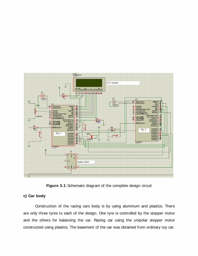
Figure 3.1:Schematic diagram of the complete design circuit
c) Car body
Construction of the racing cars body is by using aluminum and plastics. There
are only three tyres to each of the design. One tyre is controlled by the stepper motor
and the others for balancing the car. Racing car using the unipolar stepper motor
constructed using plastics. The basement of the car was obtained from ordinary toy car.

We implemented the readymade basement to our design by doing some modification.
Circuitry of the design was placed on top the basement. The dimension of the car is
25cm in length and 10cm in width. Height of the car model is 6cm, without the circuit
install in the car design.
Body of the bipolar control car was build by using aluminium. It is constructed by
hand. Same concept as the unipolar motor, there are only three tyres in the design and
the circuit was placed on top of the basement. The car model gain power from V12
battery source. The length of the model is 20cm and width is 10cm. Height of the car
model is 18cm.
Figure 3.2:Car body structure using aluminium

Figure 3.3 :Car body structure using plastic
3.1.2 Software
The software’s that we used in developing the project is MPLAB and Proteus.
MPLAB Integrated Development Environment (IDE) is an integrated toolset for the
development of embedded applications employing and PIC microcontrollers. MPLAB
IDE runs as a 32-bit application , is easy to use and includes a software components
for fast application development and super-charged debugging. MPLAB IDE also serves
as a single, unified graphical user interface for additional Microchip and third party
software and hardware development tools. Moving between tools is a snap, and
upgrading from the free software simulator to hardware debug and programming tools
is done in a flash because MPLAB IDE has the same user interface for all tools. The
codings in the microcontroller can be coded using C language or Assembly language.
Our group used C language to code the microcontroller instead of A. C language is
easier for us to use because we are more familiar to that language. The codings was
coded into the microcontroller using programmer. In the project, the codings plays an
important role as it functions as the ‘main brain’ in the circuit. If the codings is not
successfully done, the circuit will not function.
Proteus is a low-cost package offering facilities for schematic drawing, SPICE
simulation, and PCB layout. The ProSPICE simulation module also includes simulation of

the PIC16F877A microcontroller, and a range of interactive peripheral models such as
LCD displays, matrix keypads, and DC motors. Proteus is an easy-to-use application for
creating printed circuit-board layouts, and is good for students working on small
projects. Proteus creates simple PCBs with 16 copper layers, two silk screens, and four
user/mechanical layers. Completed designs are suitable for reports, tutorials, or
articles. During testing, we found we were forced to register the program before most
of the basic functions would work. Proteus is a great program for creating PCBs.
Simulations of our design cannot be done in Proteus because some of the components
that used are not in the Proteus library such as stepper motor. We only used the
software to design the PCB layout.
Figure 3.4: Design of PCB layout using Proteus ( Circuit inside the remote control)

Figure 3.5 : Design of PCB layout using Proteus ( Circuit inside the racing car)
3.1.3 Dual Full Bridge Motor Driver ( L298)
The model of motor driver that we are using is SD02B. As we studied the circuit
in the driver, we found out that L298 dual full bridge driver is used to drive the bipolar
motor. The dual full bridge driver is embedded inside the motor driver. Operating
supply voltage is up to 46V and total DC current is 4A. The L298 is an integrated
monolithic circuit. It is a high voltage and high current dual full bridge driver design to
accept standard inductive load such as relay, solenoid, DC and stepping motor. Two
enable inputs and are provided to enable or disable the device independently of the
input signals. The emmiter of the lower transistor of each bridge are connected
together and the corresponding external terminal can be used for the connection of an
external sensing resistor. An additional supply input is provided so that the logic works
at a lower voltage. It is a full bridge motor driver intended for a wide range of
automotive applications. Experimentally, we can drive two stepper motors using it. We
can directly interface the input with microcontroller to select the motor direction velocity
and break condition.

Figure 3.6 : Pin connection of L298.
3.1.4 Freewheeling Diode
There are also 4 pairs of freewheeling diodes in the SD02B motor driver.
Freewheeling diode is put into the circuit to protect the switching device from being
damaged by the reverse current of an inductive load. It is normally placed in a circuit so
that it does not conduct when the current is being supplied to the inductive load. When
the current flow to an inductor is suddenly interrupted, the inductor tries to maintain
the current by reversing polarity and increasing the voltage. Without the "freewheeling
diode" the voltage can go high enough to damage the switching device. With it, the
reverse current is allowed to flow through the diode and dissipate.
Figure 3.7 : Simple circuit of freewheeling diode

Figure 3.8 : Location of Dual Full Bridge and Free Wheeling Diode in the motor driver.
3.2 Description
3.2.1 Stepping
In the real world, there are types of phase current waveform which is full step,
half step and microstep. Full stepping motor have 200 rotor teeth or 200 full steps per
revolution of the motor shaft. Dividing the 200 steps per revolution (360o), each full
step angle is 1.8o. Normally full step angle achieved by energizing both windings while
reversing the current alternatively. Essentially, one digital input from the driver is
equivalent to one step.

Figure 3.9 : Full step stepper motor revolution
Half step means that the motor is rotating 400 revolutions per minute. In this
mode, one winding is energized and the two windings is energized alternatively,
causing the rotor to rotate at half the distance (0.9o). Half stepping is more practical
solution. Although it provides less torque, half step motor reduces the amount
‘ jumpiness’ inherent in running in a full step mode.
Figure 3.10: Half stepping stepper motor revolution degree
Microstepping is relatively, new stepper motor that controls the current in the
motor windings to a degree that further subdivides the number of positions between
poles. Microsteppers are capable of rotating at 1/256 per step or over 50,000 steps per
revolution. Dividing the 50,000 steps per revolution (360o), each full step angle is
0.072o.. In our design, both our control car stepper motor driver is using microstepping
steps to generate the rotations. Microstepping stepper motor is used to achieve two
objectives that are, increase the position of resolution and achieve smoother operation
of the motor. Microsteppping is typically used in applications that require accurate
positioning and fine resolution over a wide range of speed. It limits noise and resonance
problems. Microstepping works on the principle of gradually transferring current from
one winding to the other. This is achieved by pulse width modulating (PWM) the
voltage across the windings of the motor. The duty cycle of the signal charging one

winding is decreased as the duty cycle of the signal charging of the next winding is
increased.
Analysis
Stepping motor move by rotating in steps of predetermined degrees called step angle.
The degree rotated and the speed of rotation are easily controlled using electrical signal
called pulses. A pulse is an electrical signal that repeats ON and OFF as shown in Figure
3.11. Each cycle of ON and OFF ( one cycle) is called a pulse. In our design, the ON
period illustrates when the circuit is supplied by +5V and OFF period when 0V voltage
supplied.
Figure 3.11 : Output motor waveform.
T is the time taken for each revolution. By dividing 60s ( a minute) with T obtained, the
revolution per minute value was find.
Microstepping analysis

Figure 3.12 : Output waveform for microstepping circuit using oscilloscope
Referring to the waveform produced in Figure 15, the length of each complete
waveform 1.4 of the box. As we set the oscilloscope, each box wavelength is 1ms per
box.
msmswavelength 4.114.1
For each step, the time taken is 1.4ms. So, per revolution the numbers of steps
produced are:
stepsmss 857,42)4.1(60
Approximately, the steps produced per revolution are 43,000. With the result obtained
each step angle is 0.00837o.
3.2.2 H- bridge
Figure 3.13 : Structure of H- bridge (highlighted in red)

H-bridge is an electronic circuit which enables a voltage to be applied across a
load in either direction. In the design the H – bridge circuit was build inside the bipolar
stepper motor only. These differentiate between unipolar and bipolar motor. The circuit
is used in applications to allow stepper motors to run forwards and backwards. H-
bridge is built with four switches. When the switches S1 and S4 are closed (and S2 and
S3 are open) a positive voltage will be applied across the motor. By opening S1 and S4
switches and closing S2 and S3 switches, this voltage is reversed, allowing reverse
operation of the motor. Using the nomenclature above, the switches S1 and S2 should
never be closed at the same time, as this would cause a short circuit on the input
voltage source. The same applies to the switches S3 and S4. The H-Bridge arrangement
is generally used to reverse the polarity of the motor, but can also be used to 'brake'
the motor, where the motor comes to a sudden stop, as the motor's terminals are
shorted, or to let the motor 'free run' to a stop, as the motor is effectively disconnected
from the circuit. The following table summarizes operation.
Analysis
Table 3.1 : Analysis result of the H – bridge circuit
S1 S2 S3 S4 RESULT
1 0 0 1 Motor moves right
0 1 1 0 Motor moves left
0 0 0 0 No movements
0 1 0 1 Motor brakes
1 0 1 0 Motor brakes

Flowchart of input signal
Yes
No
Yes
No
Input Bit from potentiometer
(analog signal to digital signal)
Received
Bit = 0?
Circuit turn OFF
Turn ON
Receive Bit
1 to 10 ?
Car brake
Motor rotates
Received Bit
10 to 100

3.3 Problem encountered
In the final design built, there are some features was modified or eliminated as
we encountered some problems. There are two features that we modified which are
radio frequency module (RF) and encoder.
The radio frequency signal is totally eliminated from our design. We are using
wire cables instead of wireless. The reasons we eliminate the feature is the signal in the
RF is interphasing with the other group frequency. Most of the other groups are using
the same model of RF with the same frequency (433MHz). Distortion of information
produced and consequently the data received or transmitted is not the acquired signal.
In the design, the functionality of RF is very important. If the RF is not working properly,
the design will become a big failure. As we discussed among the team members, we
are not willing to take any risk, so we change the RF to the wire cables. Furthermore,
the main purpose of the project is to build test board to stepper motor.
The second feature that we modified is the encoder, speed calculation. As we
proposed, the encoder should detect the speed of the stepper motor. Unfortunately, the
encoder that we are using was broke during the installation part. Because of time
limiting factor, we modified the calculation speed mechanism. Microcontroller itself
calculates the rotation of the stepper motor. Data collected from the test done in lab to
come out with speed and torque equation. This equation is programmed in the
microcontroller. Referring to this equation, the speed calculated.
We also encountered a problem during PCB layout. The PCB fabrication process
was perfectly done. But during troubleshooting after soldered the components , the PCB
circuit does not function as expected although the circuit is approved. Many tests have
been done throughout the project for the PCB. The failure of the circuit is because of
electromagnetic effect. Furthermore, the copper in the PCB board is being oxidized to
the surroundings. As a result, we use straight board instead of PCB board.

Chapter 4
TEST DATA WITH PROOF OF FUNCTIONAL DESIGN
4.1 LCD test
We are using LCD type JDH162A for our product and we are using C
programming to interface the LCD with the microcontroller. The circuit design is built on
the Porteus 7 Professional program. The failure circuit is shown on the Figure 4.1a and
the successful circuit is shown in Figure 4.1b. The program is simulated on the MPLAB
IDE v8.1 and it is send to PIC by using Pickit2 v2.55. The result of the experiment for
the LCD is shown in Table 4.1.
Table 4.1 : Test result of LCD screen
Test Result Note
1
(refer to Figure 4a) fail
There are short circuit occur.
The LCD, PIC and voltage regulator is burn.
Some connection are wrong One of the connection not
connected to the ground and cause the short circuit
2
(refer to Figure 4b) success
Circuit is successful connected
The character programmable is display successfully

No component are burn
Figure 4.1a : Failure circuit of LCD screen
Figure 4.1b : Successful circuit of LCD screen

4.2 Speed control
This is a basic circuit diagram that controls the stepper motor speed with voltage
regulator 7805 and potential meter shown in Figure 4.2a. When vary the potential
meter will produce the analogue signal from 0.1V until 5V into microcontroller. In the
microcontroller, ADC converter will convert the analogue input to digital output in order
to decide the stepper motor speed. The output of the speed control circuit when varied
the potential meter.
The speed control circuit connected to PIN 2 of PIC16F877A that the analogue
signal 0-5V sends into microcontroller in order to convert to digital signal. The eight LED
connected from the PIN 33 until PIN 40 of PIC which will indicate the digital signal
changing from 00000000 to 11111111 when the potential meter was varied.
Figure 4.2 : Diagram circuit of voltage regulator.

4.2.1 Measuring output of speed control
According the above circuit diagram, the digital signal changing from 00000000
to 11111111 when varied the variable resistor which the digital signal indicate the
voltage changed from the regulator IC 0 to 5V.
Table 4.2 : Result of Binary code according to the output voltage
Digital signal (Binary Code) Output voltage (Vo) V
00000000 0
00001010 0.18
00010100 0.33
00011110 0.55
00101000 0.70
00110010 0.92
00111100 1.12
01000110 1.31
01010000 1.47
01011010 1.68
01100100 1.90
01101110 2.08
01111000 2.33
10000010 2.50
10001100 2.60
10010110 2.89
10100000 3.02
10101010 3.31

10110100 3.51
10111110 3.68
11001000 3.89
11010010 4.10
11011100 4.22
11100110 4.32
11110000 4.65
11111010 4.75
11111111 4.89
4.3 PCB layout
Below are the PCB layouts that using the Proteus software to design the circuit
track. Further more, printed the PCB layouts on the transparent and then etched it.
Then drilled the holes in order to put the components and soldered all the parts on the
PCB
4.4 Radio Frequency
Hardware:
RF-Module (433MHz)
i) RF Transmitter Module

Figure 4.4.1 RF Transmitter Module (433MHz)
Table 4.4.1 Specification of RF- Transmitter Module
Specifications RF Transmitter Module
Operating Voltage 3V to 12 V
Operating Current Max: 400mA for 12 V supply
Min: 9mA for 3V supply
Frequency 433MHz
Transfer Rate 10Kbps
Antenna Length 18cm
There are 3 pins to connect in the RF Transmitter module. The DATA pin is
connected to the TX pin of the Microcontroller. VCC pin connect to the supply voltage
and GND connect to ground. The antenna can extend with any wire but for better result,
a 50 Ohm coaxial cable is used. The length of the wire as antenna is about 18cm long.
ii) RF-Receiver Module

Figure 4.4.2 RF Receiver Module (433MHz)
Table 4.4.2 Specification of RF-Receiver Module
Specifications RF Receiver Module
Operating Voltage 5.0V ± 0.5V
Operating Current ≤5.5mA for 5.0V supply
Frequency 433MHz
Transfer Rate 10Kbps
Antenna Length 18cm
There are 5 pin to connect for the RF receiver module. The DATA pin of the RF
Receiver Module is connecting to the RX pin of microcontroller. The VCC pin connects to
the 5v supply and the GND pin to ground. The ANT is the antenna of the receiver and
can be extend with any wire. The length of the wire is 18cm for better result.
Microcontroller
i) PIC16F877A

PIC16F877A is an 8-bit microcontroller. It has 5 I/O port where each I/O port have 8
I/O pins. There is 8 A/D input and 15 interrupt. There also implemented with parallel
Slave port in this microcontroller. Table below shows the specification PIC16F877A.
Table 4.4.3 show the specification of PIC16F877A
Model Operating
Frequency
Flash
Memory
(world)
Interrupt Capture/
Compare/PWM
modules
Serial
Communications
I/O
Port
10-bit
Analog-
to-
Digital
Module
16F877A DC-
20MHz
8K 15 2 USART 5 8 Input
channel
Circuit Diagram
i) Transmitter (remote control circuit)
Figure 4.4.4 Circuit diagram of transmitter.

PIC16F877A operate in 5v. Hence, 7805 which is a 5 volt voltage regulator is use
to regulate the input voltage which is 12 volt to a stable dc 5 volt. Two capacitors are
connected to the voltage regulator as shown in the circuit above as a coupling capacitor
to reduce the noise in the regulator and allow the regulator to produce a stable dc 5
volt to be supply to the microcontroller. A 20MHz crystal is connected to pin 15 and pin
16 of the PIC as an oscillator. The oscillator determined the process speed of the
microcontroller.
RF transmitter module also needs a 5 volt supply voltage. The Vcc of the pin is
connected to the pin 25 of the microcontroller. This is done so that the transmitter
input voltage is supply by the microcontroller and the transmitter is always turning off
whenever there is no transmitting process going on. From the table 1.0, the transmitter
needs at least 9mA to operate and PIC16F877A is able to supply 5 volt with the current
of 25mA which is sufficient to operate the transmitter. The data pin of the transmitter is
connected to the TX pin of the microcontroller which is pin 25 for PIC16F877A. TX pin is
for the use of serial communication interface which will transfer 8 bit data to the
transmitter to be transmit.
A potentiometer is connected to pin 2 of PIC16F628A to give signal to the
microcontroller to start transmit each time the potentiometer is turned. The analog-to-
digital signal (0-255) is given to the microcontroller to start transmit. To enable the
potentiometer give a signal (0-255) to the microcontroller, the pin 1 is connected to
high signal (5V) and the pin 2 is connected to the pin 2 of microcontroller, and pin 3 is
connected to the ground (0 V). Therefore, the potentiometer can vary the voltage from
0 V to 5 V. After analog to digital conversion by microcontroller, the potentiometer can
vary the digital value from 0 until 255 which is acting as the speed control for the car.
The 8 LED are connected to the pin 33 to pin 40 as an indicator (0-255) of the
program is running whenever the potentiometer is changing. The 330 ohm resistor is
connected in series with the LED in order to protect the LED damage by the current.
The LED used operate at a current of 15mA and after adding the 330 ohm resistor
series with the LED, the output current of the microcontroller is being reduce to 12mA
which is safe for LED.

ii) Receiver Circuit
Figure 4.4.5 shows the circuit of the receiver
The connection for the microcontroller and voltage regulator is the same as the
circuit for the transmitter. The RF receiver is operating at 5 volt. The Vcc pin of the RF
receiver is connected to the 5 volt supply from the voltage regulator. The data pin of
the receiver is connected to the RX pin which is pin 26 for PIC16F877A. RX pin is for the
use of serial communication interface which will receive the 8 bit data from the
transmitter for further process. In this circuit, when the receiver receive correct data
transmitted from the transmitter, the 8 Led will light on same as the transmitter else
receiver receive the wrong data.
Software
Interface RF-Module with Microcontroller
MPLAB is used as the programming software and c language is used as the
programming language. To interface RF module with microcontroller, Universal
Synchronous and Asynchronous Receiver and Transmitter (USART) or also known as
Serial Communications Interface is used. USART is used for transmit and receive serial

data. The operation of USART can be divided into two types which is synchronous and
asynchronous. Synchronous mode uses a clock and data line. Asynchronous mode does
not use clock accompanying the data. Asynchronous mode will be use in interfacing the
RF module with the microcontroller. Table below show the register and flag bit that will
be used together with its description.
Table 4.4.4 Register and Description which will be used
Register Name Description
TXSTA Transmit Status and Control
RCSTA Receive Status and Control
TXREG Write Transmit Data Register
RCREG Write Receive Data Register
SPBRG Setting Baud Rate
PIR1 Peripheral Interrupt Flag Register
PIE1 Peripheral Interrupt Enable Registers
Flag Bit Name Description
TXIF Located in PIR1 (bit 4) which is use to
check whether TXREG is Full or Empty
RCIF Located in PIR1 (bit 5) which is use to
check whether RCREG is Full or Empty
OERR To test over run error for the RCREG
Register
TXEN Transmit Enable of Disable bit
RF-Module
4.4.1 Theory and Setting Asynchronous Mode Of USART for Transmitter
In previous section, it is shown that the data pin of the transmitter module is
connected to the TX pin of the microcontroller. Seem TX pin normally used as a digital

I/O port, to enable the TX port as a serial port, SPEN which is bit 7 in RCSTA have to be
set. Bit six in TRISC of PIC16F877A have to be clear in order to make the TX pin as an
output pin. TXSTA is the transmit control register for the microcontroller. This register
has to be initializing correctly in order to make the transmission work. By referring to
the data sheet, the TXSTA is initialized as B'00100000' which mean that it transmit 8bit
data in asynchronous low speed mode. Figure 4.4.3 shows the representation of each
bit of the TXSTA register and Figure 4.4.4 show the setting of the register in the
program.
Figure 4.4.6 Representation of Each Bit in TXSTA Register
Figure 4.4.7 Setting of the Register for USART

Next is to set the baud rate of the transmitter. Baud rate refers to the speed at
which the serial data is transferred, in bits per second. In Asynchronous mode, the
baud rate generator sets the baud rate using the value in the SPBRG register. The
BRGH bit in TXSTA selects between high and low speed options for greater flexibility in
setting the baud rate. From the initialization of TXSTA shown above, the BRGH is clear
which mean that the baud rate is in low speed and the SPBRG register is set to 129
where the rate is 2.4K bit per second. The Baud rate for both transmitter and receiver
must be the same in order for the data transmitted to receive in the receiver. The baud
rate can be calculated with the formula shown below.
퐷푒푠푖푟푒푑 푏푎푢푑 푟푎푡푒 = 퐹표푠푐
64(푥 + 1)
Where, Fosc = frequency of crystal used
X= value that will be set in the SPBRG register
Example:
Taking the desired baud rate = 2.4K
2.4퐾 =20푀
64(푥 + 1)
푥 = 129.21
푥 ≈ 129
When a 1 byte digital data is being transmitted, it is transmit from the less
significant bit to the most significant bit. This means that the transmitter transmits
digital data bit by bit to the receiver. Figure 4.4.5 shows how the signal is transfer in
asynchronous mode.

Figure 4.4.8 Signal Transfer in Asynchronous mode
From Figure 4.4.5 the signal is high when no transmission (or reception) is in
progress and goes low when the transmission starts. The receiving device uses this low-
going transition to determine the timing for the bits that follow. The signal stays low for
the duration of the START bit, and is followed by the data bits, Least Significant bit first.
The USART can transmit and receive either eight or nine data bits. The STOP bit follows
the last data bit and is always high. The transmission therefore ends with the pin high.
After the STOP bit has completed, the START bit of the next transmission can occur as
shown by the dotted lines.
During transmitting data, the heart of the transmitter is the Transmit Shift
Register (TSR). This register obtain the data from the transmit buffer, TXREG. Hence,
to transmit a data to the receiver, first is to move the desire transmit data to the TXREG
then it will load to TSR to be transmitted. To check whether the data in TXREG had
been move to TSR, the flag bit TXIF which located in the PIR1 is checked. If TXREG is
empty (means the data already load to TSR) the flag bit TXIF will be set. Hence new
data can be load to TXREG to be transmitted next. The Bit TXEN in TXSTA show in
Figure 4.4.6 is always set so that all the data in TSR will be transmit.

Figure 4.4.9 Block Diagram Showing the transmitter’s program runs
4.4.2) Theory and Setting of Asynchronous Mode Of USART for Receiver
RCSTA is the receive control register for the microcontroller. This register has to
be initializing correctly in order to make the receiver work. By referring to the data
sheet, the RCSTA is initialized as B'10010000' which mean that it continuously receive 8
bit data, asynchronous mode. The SPEN Flag bit in RCSTA have to be set to enable the
serial port. The baud rate for the receiver has to be the same with the transmitter.
Figure 1.7 shows the representation of each bit of the RCSTA register and Figure 1.4
show the setting of the register in the program.
Check TXIF
True
False
Move data to TXREG to be transmitted

Figure 4.4.10 Representation of Each Bit in RCSTA Register
When receiving data from the transmitter, the data is first stall in Receive Shift
Register (RSR). After that the received data is transferred to the RCREG register when it
is empty. Once the transferring process from the RSR to RCREG is complete, the flag bit
RCIF will be set. The RCREG is a double-buffered register which mean that it can store
two byte of data. When the 2nd data come in but the 1st data have not been read yet,
the data will store in the second slot of the RCREG. When the 1st data is read, the 2nd
data will move to the 1st slot and new data can be move into RCREG. However, when
the RCREG is full and the 3rd data is store in the RSR, the flag bit OERR will be set and
the data in RSR will lost. In addition, all the receive process will be stop. Hence it is a
must to clear the flag bit OERR in order to retrieve the receiving process. Flag bit OERR

can be clear by first clear the CREN and then set it again. Figure 1.8 shows how the
overrun error being detected and how it is solve.
Figure 4.4.11 Source codes detecting and solving overrun error
Testing Data (RF)
A experiment is carried out at robocon lab, sktm to test the efficiency of Radio
frequency.
No. of
tests
Distance (m) Efficiency
1 1 correct
2 2 correct
3 3 correct
4 4 correct
5 5 correct
6 6 correct
7 7 correct
8 8 correct
9 9 correct
10 10 correct
11 11 correct
12 12 correct

13 13 correct
14 14 correct
15 15 Partially correct
16 16 Partially correct
17 17 Partially correct
18 18 Partially correct
19 19 Partially correct
20 20 Cant receive
From the analysis above, the result can be concluded when the distance starts to
increase the efficiency start to decrease. From 15 m to 19 m, the data receive start to
corrupted by surrounding and after 20 m the radio frequency is out of the function.
Failure
However the Radio frequency in our project design will be replaced by the wires due to
reason below:
i) Interface by other radio frequency: Many groups are using the value of
frequency of radio frequency.
ii) Protocol : The pre-set method to transmitter and receiver cannot applied in
the the racing car because the value of speed time by time. Therefore, the
probability the receiver receive the wrong data is very high.
4.5 Car test (unipolar stepper motor)
We are testing our product at two different surfaces that is at flat surface and
also at sliding surface. The car is tested by using bipolar and unipolar stepper motor.
The data of unipolar stepper motor is shown at Table 4.4a, Table 4.4b and also Table
4.4c. From the table it is shown that at the flat surface the RPM speed of the motor

decreases when the time increases and at the mount surface RPM speed is also
decreases when the time increases. The RPM speed reach at full-speed at 3 second.
The direction and the total load (1kg) remains as constant.
Table 4.5a (flat surface)
Distance(m) Time(s) Speed(rpm)
1.80 5 115
1.80 9.36 61
1.80 51 11
Table 4.5b: Car test data sliding surface(unipolar)
Distance(m) Time(s) Speed(rpm)
0.7 3 74 (Full-speed)
0.7 5 45
0.7 13 17
Table 4.5c : Test result in different slant surface
Angle Condition Result Note
10o
Low speed
High torque Success
The car successfully climb the sliding surface
The car can stop when an input is given
High speed
Low torque

20o
Low speed
High torque Success
The car successfully climb the sliding surface
The car can stop when an input is given
High speed
Low torque Fail
The car fail to climb the sliding surface
We calculate the speed of the stepper motor by using formula given below
푣 = 푟휔
푣 = 푟2휋푛60
푛 =60푣2휋푟
푣 = 푣푒푙표푐푖푡푦(푚푠 )
푟 = 푟푎푑푖푢푠 표푓 푡ℎ푒 푐푎푟 푐표푛푡푟표푙 푤ℎ푒푒푙
푛 = 푠푝푒푒푑 푖푛 푟푝푚
4.6 Test data for encoder
In the project design, we had programmed the microcontroller to convert analog
signal to digital signals. The reason for the conversion is have many intervals between
the readings. The readings in the digital signal has 256 intervals while in analog signal
has only two readings that are for 5V and 0V. To test the speed of the encoder 8 LEDs
connected to the microcontroller . These LEDs represents the bits ( 0 to 255). 0
represent the smallest delay value while the 255 represents the largest delay value.

When the potentiometer varied, the LEDs blinking are varied. This represent the
amount of bits transmitted to the stepper motor. When the LED is in ON state , it
represented as 1 and when OFF state represented as 0. The waveform of the rotation
speed obtained by connecting the microcontroller to oscilloscope. Referring the
waveform produced the frequency for each bit waveform calculated. Some calculations
are shown as below:
a)
Figure 4.6.1: Output waveform for 175 bit.
As in the picture, the LED bit is 10101111 which is 175 decimal.
Referring to the waveform produced in Figure 4.6.1, the length of each complete
waveform is 2.2 of the box. As we set the oscilloscope, each box wavelength is 1ms
per box.
msmswavelength 2.212.2
The frequency of the waveform obtained by using this formula:

Tf 1 ; ms
f2.21
Hzf 55.454
b)
Figure 4.6.2 : Output waveform for 53 bit.
As in the picture, the LED bit is 00110101 which is 53 decimal.
Referring to the waveform produced in Figure 4.6.2, the length of each complete
waveform is 6.8 of the box. As we set the oscilloscope, each box wavelength is 0.1ms
per box.
msmswavelength 68.01.08.6
The frequency of the waveform obtained by using this formula:
Tf 1 ; ms
f68.01
Hzf 6.1470

The tests were repeated for 20 times with different number of bits. The results are as
Table 4.6.
Table 4.6: Data result of frequencies versus bits
No. of
tests
Bit T ( time of pulse) (s) Frequency (f) (Hz)
1 2 0.00004 25,000
2 4 0.000064 15625
3 7 0.0001 10,000
4 15 0.0002 5,000
5 17 0.00023 4347.83
6 31 0.0004 2500
7 33 0.00043 2325.58
8 37 0.00048 2083.33
9 53 0.00068 1470.6
10 64 0.00084 1190.48
11 70 0.00088 1250
12 95 0.00104 961.54
13 106 0.0014 714.28
14 143 0.0018 555.55
15 159 0.0018 555.56
16 165 0.0021 476.19
17 175 0.0022 454.55
18 205 0.0026 384.88
19 230 0.0030 333.33
20 255 0.0033 303.03
4.7 : Car Testing Power
In this section, our group tested the motor by using the prototype that we had built. We troubleshooted the design to find weather it is successfully worked or not. We test

the car in different speed (RPM) and also the road situation. The test runs data shown at the table 4.7a.
Table 4.7a: Shows the result of the movement of the car at flat road.
Distance(cm) Time Speed(RPM) Note
180 9.36 344
The car move at the
middle speed
The car able to move
forward.
180 51 68
The car move at the low
speed
The car able to move
forward with high torque.
180 5 5
The car move at the high
speed.
Torque very low
Table 4.7b : Shows the car movement result when run up the 300 hill.

Distance
Time Speed(RPM)
Note
Constant 13 148
The car move at the low
The car able to move
forward.
Constant 5 300
The car move at the
middle speed
The car able to move
forward
Constant 3 Full speed
The car move at the high
speed.
Torque very low
By comparing the results obtained, we can conclude that the car speed is
proportionally dependant on the road condition. Based on our observation in the Table
4.7b, when the car at low speed, the time taken is 13s but when the car is high speed,
the car only 3s to going up the hill. This conclude that when the motor in full speed
state , the torque is low while when the motor is in low speed , the torque produced is
high.
Chapter 5

SUMMARY
5.1 Final cost
Part Type of component Quantit
y
Cost of each
component(R
M)
Total cost of
the
component(R
M)
Circuit design
Motor driver 1 135.00 135.00
Stepper motor 1 50.00 50.00
Radio frequency 2 55.00 110.00
Encoder 1 60.00 60.00
LCD(JHD162A) 2 30.00 60.00
PIC(16f877a) 5 25.00 125.00
Voltage regulator 5 6.00 6.00
Oscillator 2 3.50 7.00
IC socket 40 pin 2 0.70 1.40
Switch (push button) 4 0.50 2.00
Switch (toggle) 1 1.80 1.80
PCB connector
(4 ways) 1 1.00 1.00
PCB connector
(2 ways) 1 0.50 0.50
PCB connector
(12 ways) 2 1.50 3.00
Straight pin header
(1 x 40 ways) 1 1.00 1.00
Straight female
header (1 x 40 ways) 1 1.00 1.00
PCB board 1 22.00 22.00

Prototype Box 1 3.00 3.00
Total cost 589.70
5.2 Technical part schedule
No. Team member name Technical part
1 Goai Teck Liang Radio frequency
Interface the stepper motor with
the remote control
2 Tamil Selvam Encoder
Encoder detect the speed
Send the output of stepper
motor and send it to the LCD
3 Siti Nor Nabilah LCD
Display the output of the
stepper motor
4 Wong Jih Kian Speed control
Using the potential meter to
control the speed control
5 Mohd Faizal Motor driver
Used to drive the stepper motor
5.3 Conclusion
Our product is successfully design and functioning as test board for stepper
motor for educational kit for university student. With controlled by one stepper motor it
can move backward and forward. However there is some changing followed to the
design process we have done but it still successfully works.

APPENDIX 1
LCD (liquid crystal display)
By: SITI NOR NABILAH BINTI YAHYA
For this project my part is about to works the LCD. LCD is used to display speed
for the stepper motor. For our project, we are using LCD type JDH162A. For this
product we are interface LCD and PIC. I am designing the circuit of the LCD and PIC
interfacing by referring from book and also from internet. I used C programming to
interface LCD and the PIC. The program is simulated on MPLAB IDE v8.10 and it is send
to the PIC using Pickit2 V2.55.
Speed for the stepper motor will be send to microcontroller and the
microcontroller will calculate the speed and display to the LCD screen. The successful
circuit for the LCD is then will combined with the stepper motor circuit. The
programming is change due to the function. I start create my LCD circuit interface with
PIC by using Proteus 7 Professional program.
To avoid from short circuit I’m not connected pin 15 and 16. For this product we
are designing, we are using both of the line on the LCD to display the character. The
speed and the torque of the stepper motor will be display together on the LCD screen.
The main focus to display character on the LCD is programming.
While doing this LCD part there are many difficulties comes from the
programming. Some error on the programming may affect the LCD display. Moreover
LCD is quiet sensitive because I’ve burn one LCD because of the short circuit. However
by referring to the data sheet we will know the function of the each pin of the LCD.
Reading the data sheet is very important before starting the circuit designing.
As a result of the LCD part, the programming for the LCD is successfully
simulated on the MPLAB IDE v8.10 program. Since the programming is successfully
simulated and there no problem on the circuit connection, the LCD display the character
from the program already write.

(Encoder – speed calculation )
By : TAMIL SELVAM GOVINDARAJOO
I am as the lab coordinator task is to coordinate the lab and buy the components
needed of the project. Ordinary electronics components were bought from electronic
shop in Kota Kinabalu while the unipolar stepper motor was bought from Cytron
Technology via website. Mr. Liau had sponsored us a bipolar stepper motor. As the
objective of our project is to differentiate between unipolar and bipolar stepper motor.
My task was designing the encoder circuit to detect the speed of the stepper
motor. Encoder RE08A was used to detect the speed. The encoder detects the speed
and sends the information to the microcontroller. Microcontroller processes the
informations and calculates the speed. Via cascade microcontroller the information sent
to the microcontroller embedded inside the remote controller and display the speed at
the LCD screen. The encoder is connected to the motor driver. Unfortunately, during
the installation of the encoder, one of the shaft broken. The speed detection will be
disturbed without the shaft.
So, I modified the speed detection mechanism without using the encoder. It is
totally involving the programming part. The microcontroller itself will calculate the
speed of stepper motor. Research of the speed equation was done in the lab and using
the equation the microcontroller been programmed.
Stepper motor speed control
By Wong Jih Kian
The stepper motor speed control is a basic circuit to convert analogue signal to
digital signal and control the stepper motor rotation speed. This circuit operates with
the PIC16F788A which the analogue signals from 0 to 5V to digital signals from

00000000 to 11111111. Basically, it needs one regulator 7805 IC, one potential meter
10Mohm, two 100µF capacitors, and one LED.
Firstly, construct the speed control circuit on test board in order to make sure
the output tested function vary from 0 to 5V when 12V input connected and potential
meter was varied. After tested, connect the output of speed control circuit to the pin 2
of PIC as well as write the program for PIC which can convert the analogue signal to
digital signal. Hence, the digital signal changing from 00000000 to 11111111 when
varied the potential meter in control part that the digital output signal shown from pin
33 until pin 40 by using LED in stepper motor part..
Furthermore, the MPLAB IDE V8.10 program used to simulate then transfers it to
the PIC using Pickit2 V2.55. This circuit construct in control part of stepper motor that
control the speed and two way direction in forward and backward direction. The two
way direction button connected to the pin 15 and 16 of PIC. The speed of stepper
motor would show on LCD when the potential varied.
This circuit design not so much difficulty to construct but what is important is the
programming of PIC that program convert the analogue signal to digital signal and
digital signal changed when the potential varied in order to make sure stepper motor
rotate increase or decrease and forward or backward.
Radio Frequency
By Goai Teck Liang
Interface RF-Module with Microcontroller
RF Transmitter/Receiver Modules are very small in dimension and have a wide
operating voltage range (3V-12V). The low cost RF Transmitter/Receiver can be used to
transmit signal up to 100 meters (the antenna design, working environment and supply
voltage will seriously impact the effective distance). It is good for short distance,
battery power devicedevelopment. In this project design RF Transmitter Modules
315MHz will be used.

The application of RF includes Industrial remote control, telemetry and remote
sensing. Beside that RF also can be used as Alarm systems and wireless transmission
for various types of low-rate digital signal. In addition RF can be used as remote control
for various types of household appliances and electronics projects.
MPLAB is used as the programming software and c language is used as the
programming language. To interface RF module with microcontroller, Universal
Synchronous and Asynchronous Receiver and Transmitter (USART) or also known as
Serial Communications Interface is used. USART is used for transmit and receive serial
data. The operation of USART can be divided into two types which is synchronous and
asynchronous. Synchronous mode uses a clock and data line. Asynchronous mode does
not use clock accompanying the data. Asynchronous mode will be use in interfacing the
RF module with the microcontroller. Table below show the register and flag bit that will
be used together with its description.
Register Name Description
TXSTA Transmit Status and Control
RCSTA Receive Status and Control
TXREG Write Transmit Data Register
RCREG Write Receive Data Register
SPBRG Setting Baud Rate
PIR1 Peripheral Interrupt Flag Register
PIE1 Peripheral Interrupt Enable Registers
Table 1.3 Register and Description which will be used
Flag Bit Name Description
TXIF Located in PIR1 (bit 4) which is use to
check whether TXREG is Full or Empty
RCIF Located in PIR1 (bit 5) which is use to
check whether RCREG is Full or Empty
OERR To test over run error for the RCREG

Register
TXEN Transmit Enable of Disable bit
Motor driver
By: Muhd. Faizal
Motor Driver SD02B
The model of motor driver that we are using is SD02B. As we studied the circuit
in the driver, we found out that L298 dual full bridge driver is used to drive the bipolar
motor. The dual full bridge driver is embedded inside the motor driver. Operating
supply voltage is up to 46V and total DC current is 4A. The L298 is an integrated
monolithic circuit. It is a high voltage and high current dual full bridge driver design to
accept standard inductive load such as relay, solenoid, DC and stepping motor. Two
enable inputs and are provided to enable or disable the device independently of the
input signals. The emmiter of the lower transistor of each bridge are connected
together and the corresponding external terminal can be used for the connection of an
external sensing resistor. An additional supply input is provided so that the logic works
at a lower voltage. It is a full bridge motor driver intended for a wide range of
automotive applications. Experimentally, we can drive two stepper motors using it. We

can directly interface the input with microcontroller to select the motor direction velocity
and break condition.
There are also 4 pairs of freewheeling diodes in the SD02B motor driver.
Freewheeling diode is put into the circuit to protect the switching device from being
damaged by the reverse current of an inductive load. It is normally placed in a circuit so
that it does not conduct when the current is being supplied to the inductive load. When
the current flow to an inductor is suddenly interrupted, the inductor tries to maintain
the current by reversing polarity and increasing the voltage. Without the "freewheeling
diode" the voltage can go high enough to damage the switching device. With it, the
reverse current is allowed to flow through the diode and dissipate.

APPENDIX 2
Reference
Nigel Gardner PICmicro MCUC○R (An introduction to programming; The
Microchip PIC in CCS C) (2000) Bluebird Electronics.
Tim Wilmshurst Designing Embedded Systems with PIC Microcontrollers
Principles and applications (2003) Elsevier Ltd.
Dogan Ibrahim PIC BASIC Projects 30 Projects Using PIC BASIC and PIC
BASIC PRO (2006) Newnes Ltd.
Chuck Hellebuyck Programming PIC Microcontrollers with PicBasic
(2004) Newnes Ltd.
MICROCHIP PIC16F87XA\ Data Sheet 28/40/44-Pin Enhanced Flash
Microcontrollers
JHD162A data sheet(cytron technologies)
PIC16F877A data sheet(cytron technologies)
www.wikipedia.com
www.cytron.com

GROUP MEMBERS PHOTOS
Referring to the first photo. From left : G. Tamil Selvam, Goai Teck Liang, Mohd. Faisal, Siti Nor Nabilah. Not in the picture : Wong Jih Kian.
LEADER
Goai Teck Liang
WEB MASTER
Mohd. Faizal bin Mohd Aslie
PRESENTATION MASTER
Wong Jih Kian
SECRETARY
Siti Nor Nabilah bt. Yahya
LAB COORDINATOR
Tamil Selvam Govindarajoo
SOME PHOTOS DURING FABRICATION OF THE PROJECT
