final report me 450: design and manufacturing iii fall semester...
TRANSCRIPT

Final Report
ME 450: Design and Manufacturing III
Fall Semester 2007
Chainless Challenge: Human-Hydraulic Hybrid Bicycle
Team 8
Jamal Daniel
William Johnson
Alex Lagina
Timothy Li
Section Instructor
Professor Kazuhiro Saitou
December 11, 2007

2
1. ABSTRACT ............................................................................................................................ 4
2. INTRODUCTION .................................................................................................................. 4 3. INFORMATION SEARCH .................................................................................................... 5
3.1. Patent Search and Current Technology ............................................................................ 5
3.2. Technical Benchmarks ..................................................................................................... 6 3.3. Future Information Sources .............................................................................................. 6
4. CUSTOMER REQUIREMENTS AND ENGINEERING SPECIFICATIONS .................... 6 4.1 Customer Requirements ........................................................................................................ 7 Engineering Specifications ......................................................................................................... 8
5. CONCEPT GENERATION.................................................................................................... 9 6. CONCEPT EVALUATION AND SELECTION ................................................................. 11 7. SELECTED CONCEPT ....................................................................................................... 12
7.1. Gearing System ................................................................................................................. 12
7.1.1. Main gear ................................................................................................................ 12 7.1.2. Bearings .................................................................................................................. 13
7.1.3. Spur Gears ............................................................................................................... 13 7.1.4. Motor Sleeves ........................................................................................................ 14
7.1.5 Hydraulic System ...................................................................................................... 14 7.1.6 Accumulators ............................................................................................................ 14 7.1.7 3-way valves ............................................................................................................. 14
7.1.8 Fittings ...................................................................................................................... 14 8. Engineering Analysis ............................................................................................................... 14
8.1 Maximum Acceleration ..................................................................................................... 14 8.2 Motor Torque ..................................................................................................................... 15 8.3 Tire and Rim ...................................................................................................................... 16
8.4 Hub ..................................................................................................................................... 16
8.5 Hub Bolts ........................................................................................................................... 17 8.6 Superbracket ...................................................................................................................... 17
9. Final Design .......................................................................................................................... 18
9.1.1 Spacing Restrictions................................................................................................ 19 9.1.2 Axle ......................................................................................................................... 19
9.1.3 Bracket .................................................................................................................... 20 9.1.4 Main Gear ............................................................................................................... 20
9.1.5 Hub and Main Gear Assembly ................................................................................ 20 9.1.6 Motors/Motor Gears................................................................................................ 21 9.1.7 Accumulator/Pressure Regulator ............................................................................ 21 9.1.8 Hydraulic Lines and Valves ................................................................................... 21 9.1.9 One-Way Locking Needle Bearings ....................................................................... 21
9.2. Design for Manufacturing and Assembly ..................................................................... 22
9.3. Design for the Environment ....................................................................................... 22
9.4. FMEA ......................................................................................................................... 23 10.1 Aluminum Hub ................................................................................................................. 24 10.2 Bracket .............................................................................................................................. 24 10.3 Axle ................................................................................................................................... 24 10.4 Main Gear ......................................................................................................................... 24 10.5 Motor Gears ...................................................................................................................... 25

3
10.6 Additional Components .................................................................................................... 25
11. TESTING ........................................................................................................................... 25 11.1. Safety Testing ............................................................................................................. 25
11.1.1. The hydraulic system .......................................................................................... 25
11.1.2. Hub strength ........................................................................................................ 26 11.1.3. Bracket strength................................................................................................... 26
11.2. Performance Testing ................................................................................................... 26 11.2.1. Testing for maximum acceleration ...................................................................... 26 11.2.2. Testing for maximum torque ............................................................................... 26
12. Discussion of Future Improvements ...................................................................................... 26 12. CONCLUSIONS................................................................................................................ 29 13. ACKNOWLEDGMENTS ..................................................................................................... 29 14. REFERENCES .................................................................................................................. 29
15. TEAM BIOS ...................................................................................................................... 30 APPENDIX A: MAIN GEAR DIMENSIONS & CALCULATIONS AS PERFORMED BY
W07 RBS TEAM .......................................................................................................................... 33 APPENDIX B: ACCUMULATOR ANALYSIS AS CALCULATED BY W07 RBS TEAM ... 37
APPENDIX C: COMPARISON OF FITTINGS AS PERFORMED BY W07 RBS TEAM ...... 38 APPENDIX D: DIMENSIONED DRAWING OF REAR HUB ................................................. 40 APENDIX E: BILL OF MATERIALS......................................................................................... 41
APPENDIX F: DIMENSIONED DRAWING OF AXLE............................................................ 42 APPENDIX G: DIMENSIONED DRAWING OF HYDRAULIC MOTOR............................... 43
APPENDIX H: Dimensioned Drawing of Bracket ....................................................................... 44 APPENDIX I: Finite Element Analysis of Hub .......................................................................... 45

4
1. ABSTRACT
The Parker Hannifin Corporation Hydraulics Department hosts the annual Chainless Challenge,
which challenges universities to design the best bicycle with a hydraulic connection and no chain
between its pedals and drivewheel. The University of Michigan and the United States
Environmental Protection Agency (EPA) have charged us to pioneer the first U of M Hydraulic
Bicycle Team in the same spirit as the Solar Car and mini-Baha teams. The objectives of our
project are to 1) design the bicycle with the greatest possible acceleration due to a pre-charged
hydraulic accumulator and 2) design a pedaling system that allows a cyclist to continue riding
after initial acceleration. This involves the use of a hydraulic pump and motor geared to the
pedals and drivewheel, respectively.
2. INTRODUCTION
The Environmental Protection Agency (EPA), an agency of the U.S. government, was
established by President Nixon in 1970 to enforce federal pollution reduction laws and to
implement various pollution prevention programs. Today, it is undeniable that our environment
has become more hazardous than ever. The U.S. is the world leader in pollution. According to
the 2006 progress report of the EPA‘s Clean Automotive Technology Program [1], transportation
is responsible for 30% of national CO2 emissions in the US. In an effort to decrease the amount
of emissions in high-traffic areas (e.g. cities), it is noted that cycling would make a more
convenient, cleaner, and in some cases, faster alternative to driving a car or taking a bus.
Since 2004, the EPA has worked with ME 450 teams from the University of Michigan in
implementing a regenerative braking system (RBS) in bicycles, with Dr. David Swain as the
EPA sponsor/customer. When student Jason Moore and his team finally designed a working
RBS prototype in Fall 2006, Dr. Swain sent Jason and his prototype to the 2007 Chainless
Challenge as an observer. When the RBS acceleration in Jason's bicycle unofficially won the
"acceleration challenge" part of the competition, Dr. Swain assigned our project team to build a
chainless bicycle based on Jason's design so that the U of M could officially enter and win the
acceleration part of the 2008 Chainless Challenge.
The pedal-to-drivewheel hydraulic connection works by gearing the pedals to a pump that thrusts
an incompressible fluid from a low pressure reservoir to a high pressure accumulator, which then
is released and actuates a hydraulic motor geared up to the drivewheel, accelerating the bicycle.
With a large pre-charge initially in the accumulator, the it will reach an acceleration of 10.2

5
m/s^2, which is the maximum acceleration a bicycle tire can undergo without slipping and the
acceleration that will win the acceleration challenge.
3. INFORMATION SEARCH
This section presents the results of our literature and patent search, and relates them to the
technical benchmarks to be accomplished. This section concludes with a brief description of
future information sources for our project.
3.1. Patent Search and Current Technology
The automobile automatic transmission accomplishes the very same goal that our hydraulic setup
is designed to accomplish – the transfer of mechanical energy from a rotating source to a wheel.
However, we obviously cannot use an automatic transmission on a bicycle because of its size and
weight. Several variable displacement pumps are also on the market.
As reported by the Fall 2006 Regenerative Braking team, there has been an electro-hydraulic/air
bike design that was patented in 1990 [2]. In this design the working fluid (either hydraulic fluid
or air) is pressurized either through braking or pedaling. While this design is known to be
functional, it is impractical since it takes up almost the majority of the bike, as seen in Fig 1.
The majority of its size comes from the complex gear train [3]. Our design will be compact
enough for all major components to fit inside the wheel Hub.
Figure 1: Electro-Hydraulic Bicycle Patent
A patent granted May of 2007 [2] describes a device that can adjustably control flow from
between hydraulic devices. This device could prove very useful. A way to vary the flow from a
pump to the hydraulic motor(s) would eliminate the need for multiple pump combinations.
Further research into the specifications of this device would need to be done before we can
consider using the device in our project.

6
A patent granted in June of 1998 [3] describes an infinitely variable hydraulic pedal pump for
bicycles. The pump‘s displacement is controlled by a valve on the handlebars. This device may
also prove useful in our final design.
3.2. Technical Benchmarks
Several designs for variable displacement pumps already exist. However, our design differs in
that we are implementing a hydraulic transmission and motor on a recumbent two-wheel bike
using fixed displacement pumps. Also, in order to have added stability at slower speeds, we are
going to be putting ―training wheels‖ on the rear axle, which has not yet been implemented on
any hydraulic bike. Finally, we start with a pre-charged accumulator so that short (or longer,
depending on the accumulator capacity) rides require no human work input.
3.3. Future Information Sources
Future sources of information will include fluid mechanics texts, product catalogues of hydraulic
components, component distributors, and experts such as Mr. Katsuo Kurabayashi (project
advisor), Mr. Swain, and a student familiar with the RBS design, Jason Moore. Regarding
manufacturing issues, we could consult Bob Coury (machine shop coordinator).
4. CUSTOMER REQUIREMENTS AND ENGINEERING SPECIFICATIONS
Our information will come primarily from experts who have a great deal of experience working
with previous teams on the hydraulic bike wheel with regenerative braking, both Dr. Swain and
Jason Moore. When a hydraulic pump manufacturer/retailer is located, we will be consulting
with them to ensure we purchase suitable pumps and motors. We will also likely be consulting
numerous textbooks in relation to fluid mechanics, and finite element analysis. Our machining
and manufacturing consultant will be machine shop coordinator Bob Coury. Any additional
information will be acquired through use of the internet.
Component Function
Pedals
Low pressure reservoir
Powers hydraulic pump.
Receives fluid during launching.
High pressure
accumulator
Receives fluid from pre-charge and pumping from pedals.
Hydraulic pump Moves fluid from low to high pressure accumulator; powered by human
pedaling.
Hydraulic motor Actuates when fluid is passed through from high pressure to low pressure

7
accumulator; in the process, accelerates the bicycle via bevel gear
connections to main gear.
Bevel gears Translate motion of the pump/motor to the bicycle wheel via main gear.
Main gear Turns the bicycle wheel using motion of bevel gears.
Table 1: List of component function
4.1 Customer Requirements
The basic rules of the Chainless Challenge give us a foundation from which to design our bicycle.
The following bulleted list outlines the rules set forth by Parker for all bicycles entered in their
challenge:
- Use hydraulic motive power
- No direct connection between pedal gear and rear-wheel or drive gears.
- One person per bicycle
- Use biodegradable fluid
- Must complete course
- Meet all appropriate safety codes
o Multiple, fully-active independent brakes for fail-safe braking
o Start, compete, and stop unassisted
o Functional rear-view mirrors
o Guards over sprockets and other components
- Human powered – no electric motors or internal combustion engines
- Energy may be stored in hydraulic accumulator at the start of the course
Because we have only a third the time given to the rest of the teams that will be participating in
the Parker Chainless Challenge, we have decided in collaboration with our sponsor David Swain
of the EPA only to focus on achieving maximum acceleration with our bicycle. Taking this and
the rules set forth by Parker into consideration, the updated customer requirements are shown
below.
- Maximize acceleration
o Lightweight
o High efficiency
o Ensure static friction rather than kinetic (no wheel slippage)
- Biodegradable hydraulic fluid
- Replace chain with hydraulic motor-accumulator setup
- Apply torque to rear wheel
- Cover components
- Front and rear brakes
- Rearview mirror
- No electric motor or combustion engine
- Stability at low speeds

8
In addition, there are some unstated requirements that we will need to meet in order to be
competitive in the challenge. These are outlined below:
- Achieve top speed of 40 mph
- Ensure motors run in efficient range (1000-4000 rpm)
- Remain upright without assistance at low speeds or when stopped
Because of the complex nature of the Chainless Challenge, there are many goals to be met, and
many specifications to consider in an attempt to meet those goals. In our conversations with Dr.
Swain, we concluded that we would focus first and foremost on the acceleration portion of the
challenge, with the remainder of the design to be completed if time allows later in the semester.
As such, our design specifications are as shown in Table 2 below.
Engineering Specifications
We have calculated that we will be able to achieve an acceleration of about 10.24 m/s2. This will
ensure rapid acceleration without the rear wheel slipping. This acceleration equates to a torque
on the rear wheel of 269 N-m. The bicycle‘s top speed will be theoretically unlimited, but our
goal is to accelerate the bike to approximately 40 mph using a precharge of fluid in a hydraulic
accumulator at 2 kPsi. Based on the work of prior teams, we have assumed an efficiency of
approximately 70%, a maximum system working pressure of 4 kPsi, and will be using a wheel
width and diameter of 4‖ and 26‖, respectively. For the acceleration portion of the challenge, the
bike will use a 6 gallon accumulator. The bike will be powered by two hydraulic motors, whose
displacements sum to 5.6 c.c.
Engineering Specifications Target Value
Wheel width and diameter 4‖ and 26‖, respectively
Top operating speed of bicycle 40 mph
Approximate efficiency > 70%
Maximum launch torque 269 N-m
Maximum system working pressure 4 kPsi
Total weight of hydraulic system < 22 lbs
Motor displacement 5.6 c.c.
Maximum volume of fluid 6 Gal
Table 2: Engineering specifications

9
Figure 2: QFD diagram
5. CONCEPT GENERATION
Based on our FAST diagram below, the task function of our bicycle, ‗maximize acceleration,‘
boils down to 8 major functions: pump fluid, store fluid, channel fluid, direct fluid, transmit
torque, optimize gear-ratio, place gear, and place motors. We limited the ‗store fluid‘ function to
using a piston accumulator, the ‗optimize gear-ratio‘ function to a 12:1 ratio, and the ―place
gear‖ to the rearwheel axle. Therefore, we only brainstormed concepts for the other 5 functions,
which are denoted by the highlighted boxes in the FAST diagram.
Figure 3: FAST diagram
Maximize acceleration
Accumulate pressure
Transmit torque
Power motor
Select configuration
Pump fluid
Optimize gear-ratio
Place gear
Maximize torque
Channel fluid
Direct Fluid
Store fluid
Place motors
10
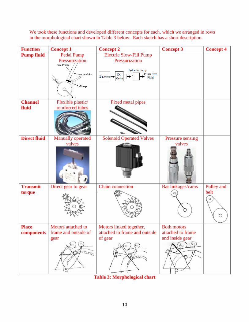
We took these functions and developed different concepts for each, which we arranged in rows
in the morphological chart shown in Table 3 below. Each sketch has a short description.
Function Concept 1 Concept 2 Concept 3 Concept 4
Pump fluid Pedal Pump
Pressurization
Electric Slow-Fill Pump
Pressurization
Channel
fluid
Flexible plastic/
reinforced tubes
Fixed metal pipes
Direct fluid Manually operated
valves
Solenoid Operated Valves
Pressure sensing
valves
Transmit
torque
Direct gear to gear
Chain connection
Bar linkages/cams
Pulley and
belt
Place
components
Motors attached to
frame and outside of
gear
Motors linked together,
attached to frame and outside
of gear
Both motors
attached to frame
and inside gear
Table 3: Morphological chart
11
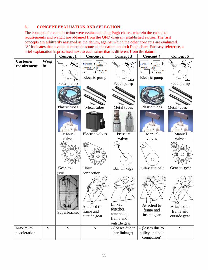
6. CONCEPT EVALUATION AND SELECTION
The concepts for each function were evaluated using Pugh charts, wherein the customer
requirements and weight are obtained from the QFD diagram established earlier. The first
concepts are arbitrarily assigned as the datum, against which the other concepts are evaluated.
"S" indicates that a value is rated the same as the datum on each Pugh chart. For easy reference, a
brief explanation is presented next to each score that is different from the datum.
Concept 1 Concept 2 Concept 3 Concept 4 Concept 5
Customer
requirement
Weig
ht
Pedal pump
Electric pump
Pedal pump
Electric pump
Pedal pump
Plastic tubes
Metal tubes
Metal tubes Plastic tubes
Metal tubes
Manual
valves
Electric valves Pressure
valves Manual
valves
Manual
valves
Gear-to-
gear Chain
connection
Bar linkage
Pulley and belt Gear-to-gear
Superbracket
Attached to
frame and
outside gear
Linked
together,
attached to
frame and
outside gear
Attached to
frame and
inside gear
Attached to
frame and
outside gear
Maximum
acceleration
9 S S - (losses due to
bar linkage)
- (losses due to
pulley and belt
connection)
S

12
Hydraulic
motive power
9 S - (Electric
motor)
S - (Electric
motor)
S
Sufficient top
speed
7 S S - (losses due to
bar linkage)
- (losses due to
pulley and belt
connection)
S
Environmenta
lly friendly
7 S - (Motors and
hydraulic lines
not enclosed)
- (Motors and
hydraulic lines
not enclosed)
- (Motors and
hydraulic lines
not enclosed)
- (Motors and
hydraulic lines
not enclosed)
Lightweight 5 S + (No hub or
superbracket)
+ (No hub or
superbracket)
+ (No hub or
superbracket)
+ (No hub or
superbracket)
Reliable 9 S + (Electric
motor)
- (losses due to
bar linkages)
- (losses due to
pulley and belt
connection)
S
Operational
rearview
mirrors
7 S S S S S
Safety 7 S - (Motors and
hydraulic lines
not enclosed)
- (Motors and
hydraulic lines
not enclosed)
- (Motors and
hydraulic lines
not enclosed)
- (Motors and
hydraulic lines
not enclosed)
Brakes 7 S S S S S
Unassisted
use
9 S S S S S
Total
+
0 14 5 5 5
Total
-
0 23 39 48 14
Total 0 -9 -34 -43 9
Table 4: Pugh chart for ‘pump fluid’
7. SELECTED CONCEPT
This section describes the selected concept of the chainless, hydraulically powered bicycle. Due
to time constraints (due to lead times) and monetary constraints (due to high priced motors,
pumps and recumbent bicycles) we have had to change our design to a standard bicycle instead
of a recumbent.
7.1. Gearing System
7.1.1. Main gear
The construction of our main gear will follow a similar procedure to that of the W07 RBS team.
We will begin with the 16‖ diameter steel gear designed by the F06 team, and remove material
such that the gear can still accommodate the required forces while being as light as possible. We
will use a revised maximum acceleration torque of 208 N-m, and we will continue to use the five
spoke design used by the W07 team. Appendix B shows their calculations, and provides a brief
description of the process we will use to design our main gear.

13
Applying a safety factor of four to our design, the maximum normal and shear stresses are 70
MPa. Using the gear design used by previous teams and equations (1) and (2) below, we find
that the normal stress is 96 MPa, which exceeds the limits of safety. Thus, we will have to
modify the gear design by increasing h to .0299m. This will bring the normal stress down to an
acceptable level of 70 MPa:
23
6
12
2
hbNs
T
hb
h
Ns
T
I
yM
(1)
hb
F
bhb
hhbF
tI
QV
2
3
12
423
(2)
7.1.2. Bearings
Previous teams used a total of 5 bearings because they used bevel gears, but we theoretically
only need three—one for the spur gear and one for the main gear. These gears produce only
radial loads. Therefore we are looking for specific bearings that consider such loads. The motors
that we are purchasing actually have in-board bearings, which will account for any side-loading
created when accelerating. We will also be adding press-fit bearings into each of the spur gears.
We plan to use one-way locking needle bearings in each of the two spur gears to facilitate more
efficient coasting of the bicycle when the hydraulic motors do not need to be in use. These
bearings will allow the motors to transmit torque to the bicycle wheel when needed, and will also
allow the spur gears to rotate around the motor axles when the bike is traveling faster than the
motor RPM. This will be of the greatest benefit to us in two circumstances; when the bicycle has
gathered momentum by traveling downhill, and when the accumulator runs out of hydraulic fluid
during acceleration. The one-way locking needle bearings will be for a shaft 5/8‖ in diameter,
and will have an outer diameter of 7/8‖.
7.1.3. Spur Gears
Each motor will have a spur gear attached to it. These gears must be able to accommodate the
one-way bearings mentioned above, and thus will need to have a bore diameter of 7/8‖. In the
interest of receiving the parts in time, we will be purchasing our gears from a catalog through
Martin Sprocket – however, this imposes some restrictions on what kind of a gear ratio we can
achieve. The smallest gear with a maximum bore of 7/8‖ has 18 teeth, while the largest gear has
180 teeth. This yields a gear ratio of 10:1, which is slightly short of our targeted 12:1 ratio.

14
7.1.4. Motor Sleeves
The motors we have purchased were supposed to have smooth, un-keyed shafts. They do not.
Because of this, we will be fabricating 1/8‖ thick sleeves to press-fit onto the shafts, which will
allow for the use of the one-way locking needle bearings discussed in section 7.1.2. The sleeves
are the primary reason we must use a 10:1 gear ratio instead of our idealized 12:1 ratio.
7.1.5 Hydraulic System
The hydraulic system for this bicycle will consist of two hydraulic motors, one hydraulic pump,
and a high side and a low side accumulator. The components will be connected using flexible
plastic reinforced hydraulic lines, all of which shall be capable of handling our peak pressure of
4000psi. As there will ideally be several different combinations of pump/motor to choose from,
the lines will be connected to several 3 way valves that will be operated manually to allow or
disallow flow through specific components.
7.1.6 Accumulators
The EPA has donated a six gallon accumulator to be used for the acceleration portion of the
Parker Chainless Challenge. This accumulator will be precharged to 4000psi for the event.
7.1.7 3-way valves
The flow of hydraulic fluid through the system and through each of the pumps or motors will be
governed by several three way valves, all of which will have to be manually operated by the
driver as per the regulations of the competition.
7.1.8 Fittings
All pressure drops due to fitting geometry have been calculated by teams previously involved in
the construction of the Regenerative Braking Wheel. The JIC 6 has been chosen as the pressure
drops for this type of fitting are much lower than for JIC 4, and only slightly higher than for JIC
8. The loss in pressure due to using JIC 6 is easily compensated by the decrease in weight due to
passing up JIC 8. The complete results and a short explanation of their calculations can be found
in Appendix C.
8. Engineering Analysis
The acceleration wheel is comprised of the tire, rim, hub, gearing, superbracket, axle, bearings
and hydraulic system. Engineering analysis for each component will be described in this section.
8.1 Maximum Acceleration
Before we can design the size and strength of our components, we must determine the maximum
acceleration of the bike. Our maximum acceleration is limited by the amount of friction
available between the drive wheel and the ground. We do not want to accelerate the wheels
beyond what static friction will allow because we will just waste energy spinning the wheels in
place. Since our bike will be rear wheel drive, the amount of frictional force available is
determined by the weight placed on the rear tire patch. Eq. 1 is used to calculate the weight
transfer to the rear tire patch during acceleration where m is the mass of the bike and rider, b is
15
the horizontal center of gravity measured from the front tire patch, L is the wheelbase, and h is
the vertical center of gravity.
(Eq. 1)
During an optimal acceleration, all of the bike and rider‘s weight will transfer to the rear. Under
these conditions the front wheel is just about to lift off of the ground. Any more acceleration
will cause the bike to wheelie and flip over backwards. Using an estimated bike and rider weight
of 90.72 kg, a 1.067 m wheelbase, and a center of gravity located 0.864 m vertically and 0.533 m
horizontally, we calculated from Eq. 1 a max acceleration of ax = 6.059 m/s2. Under this much
sustained acceleration, the bike could run a quarter mile in 11.5 seconds, reaching a speed of 156
mph! Of course our hydraulic motors will not be able to sustain this amount of power output,
but our initial acceleration will be as close as possible to the maximum without slipping.
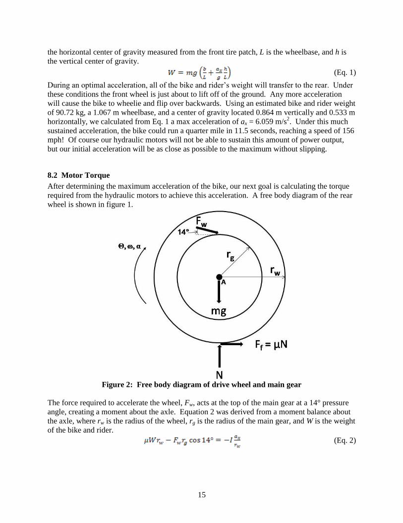
8.2 Motor Torque
After determining the maximum acceleration of the bike, our next goal is calculating the torque
required from the hydraulic motors to achieve this acceleration. A free body diagram of the rear
wheel is shown in figure 1.
Figure 2: Free body diagram of drive wheel and main gear
The force required to accelerate the wheel, Fw, acts at the top of the main gear at a 14° pressure
angle, creating a moment about the axle. Equation 2 was derived from a moment balance about
the axle, where rw is the radius of the wheel, rg is the radius of the main gear, and W is the weight
of the bike and rider.
(Eq. 2)
16
The coefficient of friction, µ, for rubber on dry concrete varies between 0.5 and 0.8[1]
. We will
use the average of 0.65. To calculate the wheel‘s moment of inertia, we approximated it as a
disk with a mass of approximately 27 kg. This approximation was derived from the combination
of the 19.78 kg main gear and a 9.07 kg aluminum hub. Using Eq. 3, we estimate the inertia of
the wheel to be I = 1.054 kg·m2.
(Eq. 3)
Solving Eq. 2 for the wheel force results in Fw = 1001 N. The estimated inertia only accounts for
11% of the total acceleration force requirement, so we should be safe with our estimates. The
true inertia will be smaller after the hub and main gear are lightened by removing excess material.
A gear mounted on the motor shaft will transmit the force, Fw, required for acceleration. The
amount of motor torque required to generate the force is calculated using Eq. 4, where rm is the
radius of the motor gear.
(Eq. 4)
Using a motor gear with a .01524 m radius, we calculate the required motor startup torque to be
τ = 15.25 N·m. We chose to split this torque up between two motors positioned at the top and
bottom of the main gear. This will allow us to design a symmetrical superbracket.
8.3 Tire and Rim
To keep the acceleration wheel as universally applicable as possible, we used the stock tire and
rim of a 24‖ men‘s mountain bike. The tread and strength of the tire and rim will be sufficient to
support the rest of the components as well as handle the torques involved. We have removed the
stock spokes and axle because they do not allow room to install our motors and hydraulics.
8.4 Hub
The hub‘s function is to provide a rigid connection between the main gear and the rim, as well as
support the rider. It serves the exact same purpose as the original stock spokes, but leaves room
for the rest of the critical components. A free body diagram of the hub (figure 2), without the
main gear assembly, shows the load of the rider and bike will be distributed through 6 points on
the hub.

17
Figure 3: (a) Free body diagram for hub. (b) Side view showing bending forces on hub
The bending moment at the outer edge of the hub is caused by the normal force of the weight of
the rider and bike. The ―lip‖ extends ½‖ from the rest of the hub to allow the main gear to ride in
a recess, keeping the entire wheel centered on the axle. The rim will ride in the V shaped groove
in the lip. We have 2‖ of space to work with between the outside of the motor gear and the
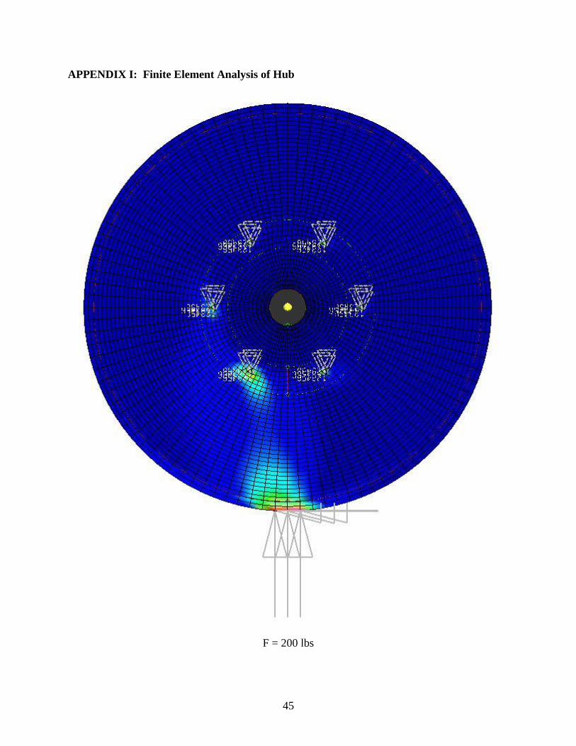
inside of the rim. A finite element analysis of the aluminum hub under a 200 lb load is shown in
figure 3.
8.5 Hub Bolts
The hub is bolted directly to the main gear using standard 1/8‖ diameter ASTM A307 bolts which
can handle tensile pressures of 414 MPa[2]
. We arbitrarily chose to use 6 bolts spaced evenly
around a 4‖ radius as shown in figure 2a. The shear force on each bolt is a combination of the
rider‘s weight, W, and the torque exerted on the wheel by the motor, τ. We use Eq. 5 to calculate
the shear stress on each bolt to be about 20.3 MPa, where V is the shear force and A is the cross
sectional area of each bolt.
(Eq. 5)
A general rule of thumb for the shear strength is 0.58 × tensile strength. These bolts can handle
our expected loads with a safety factor of about 11.
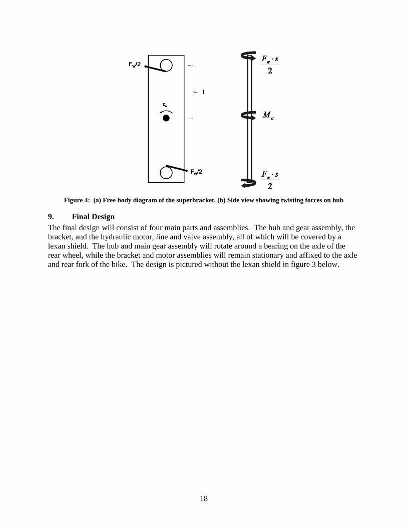
8.6 Superbracket
For the superbracket design, it is critical that the bracket not twist. If this happens, the motor
gear and main gear will not mesh properly, wreaking havoc on our bearings and gears. Since
this is such a critical component, we decided to use steel initially. Later semesters can optimize
the weight and strength of this component. A free body diagram for the superbracket is shown in
figure 4.
18
Figure 4: (a) Free body diagram of the superbracket. (b) Side view showing twisting forces on hub
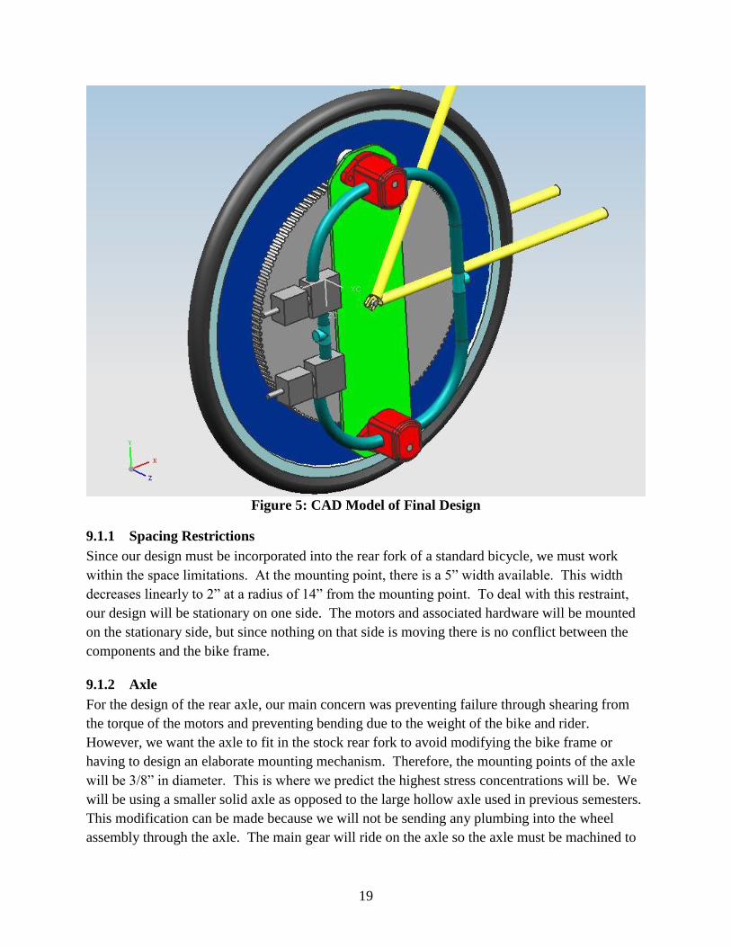
9. Final Design
The final design will consist of four main parts and assemblies. The hub and gear assembly, the
bracket, and the hydraulic motor, line and valve assembly, all of which will be covered by a
lexan shield. The hub and main gear assembly will rotate around a bearing on the axle of the
rear wheel, while the bracket and motor assemblies will remain stationary and affixed to the axle
and rear fork of the bike. The design is pictured without the lexan shield in figure 3 below.
19
Figure 5: CAD Model of Final Design
9.1.1 Spacing Restrictions
Since our design must be incorporated into the rear fork of a standard bicycle, we must work
within the space limitations. At the mounting point, there is a 5‖ width available. This width
decreases linearly to 2‖ at a radius of 14‖ from the mounting point. To deal with this restraint,
our design will be stationary on one side. The motors and associated hardware will be mounted
on the stationary side, but since nothing on that side is moving there is no conflict between the
components and the bike frame.
9.1.2 Axle
For the design of the rear axle, our main concern was preventing failure through shearing from
the torque of the motors and preventing bending due to the weight of the bike and rider.
However, we want the axle to fit in the stock rear fork to avoid modifying the bike frame or
having to design an elaborate mounting mechanism. Therefore, the mounting points of the axle
will be 3/8‖ in diameter. This is where we predict the highest stress concentrations will be. We
will be using a smaller solid axle as opposed to the large hollow axle used in previous semesters.
This modification can be made because we will not be sending any plumbing into the wheel
assembly through the axle. The main gear will ride on the axle so the axle must be machined to

20
a standard diameter to fit the main gear bearing. The ends must also be threaded so mounting
nuts can be put on.
9.1.3 Bracket
The bracket will be responsible for holding the two motors and the hydraulic line assembly in
place, and will provide a platform from which to apply torque to the main gear and hub assembly
from the hydraulic motors. In order to minimize the damage caused by corrosive materials
entering the wheel assembly, the motor bracket would ideally be made of stainless steel.
However because our goal is to maximize acceleration, weight is of greater importance to us and
therefore the bracket will be constructed out of aluminum. It will be firmly affixed to the rear
bracket of the bicycle. The majority of the stresses caused by rapid acceleration will be focused
here, so the current design calls for the bracket to be bolted to the frame as far as possible from
the axis. The exact location of this junction will depend on the geometry of the bike frame and
the correct alignment of the gears.
9.1.4 Main Gear
The main gear must rotate on rear axle with as little friction as possible, via a needle or ball
bearing. It must be the appropriate size to increase motor torque and decrease the motor speed
(the motor speed has to remain between ~1000 and ~4000 rpm under all operating conditions.
The teeth have to be able to support forces from motors and the entire gear must be able to
support the weight of the rider at axle (while remaining as light as possible). Also the gear must
be able to support the normal force from the hub. In order to ensure maximum acceleration the
weight of the gear must be kept as low as possible (lower inertia). Finally, the gear must be
mounted hub, via bolts through the spokes connecting to the hub.
We have purchased our gears through Martin Sprocket with stock specifications, in the interest
of time. Choosing from gears listed in Martin Sprocket‘s catalog, we were able to achieve a
13.3:1 gear ratio using 10 DP gears with a 14.5 degree pitch angle, with 12 and 160 teeth. The
12 tooth gears will accommodate the one-way needle bearings, which will be press-fit inside
each. We have calculated that with a 13.3:1 gear ratio we will still be able to achieve a torque of
203 N-m on the main gear, which should more than double the acceleration achieved by the
previous RBS bike.
9.1.5 Hub and Main Gear Assembly
The hub has to connect and support the rim while connecting to the main gear (via the bolts).
Since it is supporting the rim it must not bend too much under loading or the bike will be
unstable during turning. Because it connects to the rim, manufacturability becomes an issue
since it has to be so large. Also, to connect the hub to the rim the hub must be thick enough to
hold a screw coming from the inside of the rim. The only forces that need to be considered for
the design of the hub are the normal force from the ground due to the total weight of bike (plus
rider) and forces on gear mounting points from weight of bike (plus rider).

21
The main gear will be attached to a ¼‖ thick aluminum hub, which will be machined in-house.
The hub will have a ¼‖ deep recession to house the main gear and the spur gears from the
hydraulic motors. The main gear will be bolted to the hub through each of its spokes, thereby
reducing the stress on the bolts due to their distance from the axis of rotation. Both the main
gear and the hub will rotate about a bearing placed on the stationary axle of the rear wheel.
Appendix D shows a dimensioned drawing of the hub, without the gear.
9.1.6 Motors/Motor Gears
The motors must drive main gear using the high pressure flow from the accumulator. The
correct gear ratios must be chosen so that the operating range of the motors is between 1000 and
4000 rpm. There is a max pressure of accumulator of ~4000 psi but the input flows to motors
will be controlled to suit our needs. The only forces acting on the motors are from the input flow
from the accumulator and the resistive torque from the main gear (due to frication from the
wheel to ground contact).
9.1.7 Accumulator/Pressure Regulator
The main concern with the accumulator is to make sure it can hold pressure up to ~4000 psi and
that the discharge flow can be controlled to a useable rate. The accumulator will be mounted to
the bike frame, most likely behind seat (as to have as little distance as possible for hydraulic lines
to cover)
9.1.8 Hydraulic Lines and Valves
The hydraulic lines will be flexible reinforced plastic JIC6, and will enter the wheel through the
stationary shield, near the bracket. The lines will run to the two hydraulic motors and back out
of the shielded area to a six gallon accumulator mounted on the bicycle. All valves will currently
have to be operated by hand, and will be placed within reach of the rider.
9.1.9 One-Way Locking Needle Bearings
The bearings that will be used in each of the small pinion spur gears will be ordered from
McMaster-Carr and are pictured below. They are rated to operate at temperatures between -22 to
248 degrees Fahrenheit, at a maximum speed of 7501 RPM. Because the motors are only
capable of running at a maximum of 5000 RPM, these bearings will be more than adequate. Of
slight concern is the fact that the bearings are not rated with information about the loads they are
capable of supporting – however we believe that they should be within a safe working range.
The bearings also have a locking torque of 12.417 ft-lbs, or 16.835 N-m, which is greater than
the torque that will be supplied by each hydraulic motor.

22
9.2. Design for Manufacturing and Assembly
The first qualitative analysis we performed was Design for Manufacturing and Assembly
(DFMA), where we prioritized 5 most important guidelines for each of our part designs. We
considered the two parts we were machining, the shell and the bracket. The DFMA table below
summarizes the implementation of these analyses.
DFMA Guidelines Location Implementation
Facilitate orientation for
assembly
Bracket Large irregular holes are non-symmetrical about
the central axis
Avoid long narrow holes All holes are simple through holes that pass
Avoid drilling inclined surfaces through the thin bracket
Standard dimensions for ease of
machining
Holes can be fabricated with standard tools
Use standard stocks for ease of
machining
The shafts that pass through the bracket are
standard Al7075 cylindrical stock with standard
diameters
Standardize parts to reduce part
variety
Shell Identical portions of shell require machining
identical, standardized parts
Table 5: DFMA considerations in prototype
9.3. Design for the Environment
The second type of qualitative analysis we performed was a Design for the Environment (DfE)
analysis, since environmental protection is of high priority for both our sponsor (EPA) and our
customer (Parker Hydraulics). Just like the DFMA, we analyzed the designs for the bracket and
the shell, this time using the same five guidelines. We excluded the use of the guidelines
―Optimize Distribution‖ and ―Optimize End-of-Life Systems‖ because neither of these
considerations is relevant to the short-term vision of our project.
DfE Guidelines Location Implementation
New Concept Development Bracket Use of recyclable materials
Physical Optimization Use less amount of material that fits engineering
specifications
Optimize Production Techniques Start with stock material with dimensions as
close as possible to final dimensions of bracket
Optimize Material Use Manufacture bracket in the way that minimize
scarp material
Reduce Impact During Use Ensure engineering specifications are well
before failure
New Concept Development Shell Use of recyclable materials
Physical Optimization Use less amount of material that fits engineering

23
specifications
Optimize Production Techniques Start with stock material with dimensions as
close as possible to final dimensions of bracket
Optimize Material Use Manufacture bracket in the way that minimize
scarp material
Reduce Impact During Use Ensure engineering specifications are well
before failure
New Concept Development Hydraulic
fluid
As few additives as possible, ensure
biodegradability
Optimize Production Techniques Control waste during production
Reduce Impact During Use Make sure hose lines are closed and secure
Table 6: DfE considerations in prototype
9.4. FMEA
24
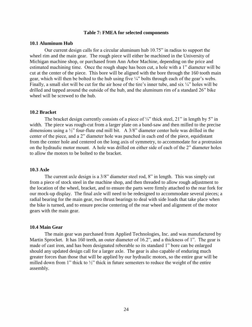
Table 7: FMEA for selected components
10.1 Aluminum Hub
Our current design calls for a circular aluminum hub 10.75‖ in radius to support the
wheel rim and the main gear. The rough piece will either be machined in the University of
Michigan machine shop, or purchased from Ann Arbor Machine, depending on the price and
estimated machining time. Once the rough shape has been cut, a hole with a 1‖ diameter will be
cut at the center of the piece. This bore will be aligned with the bore through the 160 tooth main
gear, which will then be bolted to the hub using five ¼‖ bolts through each of the gear‘s webs.
Finally, a small slot will be cut for the air hose of the tire‘s inner tube, and six ¼‖ holes will be
drilled and tapped around the outside of the hub, and the aluminum rim of a standard 26‖ bike
wheel will be screwed to the hub.
10.2 Bracket
The bracket design currently consists of a piece of ¼‖ thick steel, 21‖ in length by 5‖ in
width. The piece was rough-cut from a larger plate on a band-saw and then milled to the precise
dimensions using a ½‖ four-flute end mill bit. A 3/8‖ diameter center hole was drilled in the
center of the piece, and a 2‖ diameter hole was punched in each end of the piece, equidistant
from the center hole and centered on the long axis of symmetry, to accommodate for a protrusion
on the hydraulic motor mount. A hole was drilled on either side of each of the 2‖ diameter holes
to allow the motors to be bolted to the bracket.
10.3 Axle
The current axle design is a 3/8‖ diameter steel rod, 8‖ in length. This was simply cut
from a piece of stock steel in the machine shop, and then threaded to allow rough adjustment to
the location of the wheel, bracket, and to ensure the parts were firmly attached to the rear fork for
our mock-up display. The final axle will need to be redesigned to accommodate several pieces; a
radial bearing for the main gear, two thrust bearings to deal with side loads that take place when
the bike is turned, and to ensure precise centering of the rear wheel and alignment of the motor
gears with the main gear.
10.4 Main Gear
The main gear was purchased from Applied Technologies, Inc. and was manufactured by
Martin Sprocket. It has 160 teeth, an outer diameter of 16.2‖, and a thickness of 1‖. The gear is
made of cast iron, and has been designated reborable so its standard 1‖ bore can be enlarged
should any updated design call for a larger axle. The gear is also capable of enduring much
greater forces than those that will be applied by our hydraulic motors, so the entire gear will be
milled down from 1‖ thick to ½‖ thick in future semesters to reduce the weight of the entire
assembly.

25
10.5 Motor Gears
The motor gears were purchased from the same location as the main gear, and are also
made by Martin Sprocket. These smaller gears have 12 teeth each, an inner bore diameter of
5/8‖ and are 2‖ thick – 1‖ thick at the teeth, with a hub that is an additional inch in thickness.
This hub will be milled off the gear to allow the bracket, motor, and shaft to fit in the space
allowed by a standard bicycle rear fork.
10.6 Additional Components
All additional components have been purchased and used as-is from a supplier, including
hydraulic lines, bearings, etc.
Since our project is designed around entering the Parker Chainless Challenge, we do not have to
worry about mass production requirements. We are keeping most of the design in the rear tire
hub so that uniform operation can be achieved; when next year‘s team takes on the Chainless
Challenge they will be able to easily put on our rear tire, needing only to hook hydraulic lines to
the motors through the stationary part of the hub. In order to ensure safety and that the hub and
super bracket satisfies our engineering specifications, we will initially do a finite element
analysis on the 2 components, to figure out proper dimensions and what type of steel and
aluminum, respectively.
It is also worth noting that our design calls for one side of the hub to be rotating while the other
side remains uncovered. This is not the most ideal for environmental, safety and aesthetic
requirements. A hub with two connected sides that rotate would more satisfy these requirements,
however this type of design compromises engineering robustness. To address these safety
issues, the stationary side will be mounted to the opposite side of the hub but to the frame of the
bike, just barely coming short of flush with the rotating hub.
11. TESTING
Our prototype‘s state of incompletion limits us from testing it. This section will therefore discuss
the testing through which we would need to put our prototype once it is completed. Besides
testing its functionality, we must test our model‘s safety, performance, and efficiency.
11.1. Safety Testing
One of the most important priorities of our project is its safety and robustness of design. This
calls for testing the safety of the hydraulic system and the strength of the hub and bracket.
11.1.1. The hydraulic system
Once we obtain the hydraulic lines, we will test that all of our connections between the valves,
the motors, and the accumulators are secure. We would test its functionality by pumping a small
accumulator and then releasing the fluid through the system, checking for any leaks or
blockages. We would probably do this repeatedly with different initial pressures in the
26
accumulator. The results of this testing would then ensure whether our system is safe to install on
the bicycle.
11.1.2. Hub strength
Testing of the hub, once it is machined, would include loading it based on how much weight we
project it to undergo, which is about 200 lbs. The process would probably consist of us
measuring the vertical and bending deflection of the hub under different weights. The results
would then lead us to make a conclusion of how durable and reliable the hub is.
11.1.3. Bracket strength
Once fitted onto the bicycle rear wheel, we would need to test the strength of the bracket as it
holds the two motors and clutches onto the bicycle frame. This is especially important during
launch, when we place the most torque from the motors to the main gear. Testing would show
whether the bracket and its connection to the bicycle is strong enough to withstand the amount of
shear stress the torque would exert.
11.2. Performance Testing
The main priority of our design is good performance. Competing in the acceleration challenge,
we want the maximum acceleration. At startup, we need the maximum torque of the motors on
the wheel. These two are the most important aspects to the success of our design.
11.2.1. Testing for maximum acceleration
Testing the maximum acceleration would probably consist of two phases. Both include using the
6 gallon high pressure accumulator and releasing it all through one motor in the system and
measuring the angular acceleration and speed of the spinning rear wheel. However, one initial
test would probably be in a stationary position, with the rear wheel suspended. This would show
us the pure acceleration of the wheel in a free state. The second test would be to actually test the
wheel against the floor, letting someone ride the bicycle as we let the system start up. This would
allow us a more realistic evaluation of the prototype‘s capabilities.
11.2.2. Testing for maximum torque
Testing the maximum torque involves the same two tests as the acceleration in Section 11.2.1
above, but instead releasing the high pressure fluid through both motors instead of just one. This
would result in the greatest amount of torque possible in with our model. We would model the
12. Discussion of Future Improvements
One of the aspects we were trying to focus on was universally compatibility but in building our
prototype we realized in order to properly secure the bracket and motor assembly, the mounting

27
bracket will need to be secured to the frame of the bike. Also, the hub could be ordered to the
desired specifications with a gear machined on the inner lip of the machined-in hole. This would
allow for a decrease in weight, not needing an additional piece to bolt to the hub, as well as a
larger possible gear ratio between the motor gear and the main gear. This would also spread the
stress due to the motor gear and main gear interaction out more uniformly across the hub, as
opposed to just having a gear bolted onto the hub.
With the design of the current hub, the wheel is not very balanced, since there is the offset for the
machined in portion. Future teams might want to center the weight of the wheel for a more
symmetric design. Also, to help reduce weight the hub could be made out of fiber glasses; this
was not a possibility for this semester since we ran into many budget problems.
Future teams will need to focus on a way to power the hydraulic system which powers the
acceleration. Hydraulic pumps would possibly be attached to a pedaling system so that one could
keep standard pedaling system which pressurized hydraulic fluid through hydraulic pumps, then
provided acceleration with the hydraulic motor system presented in this report. Provided with a
estimate that an average bicycle rider can pedal anywhere from 80 to 100 rpm (professional
cyclists reaching speeds over 120 rpm) and with the right gearing system this could provide
adequate power for the challenge. Having some sort of storage device for an added boost at
some point throughout the race course seemed like a good idea; however there has not been any
research into any possible designs or concepts.

28
Figure 6: Gantt chart

29
12. CONCLUSIONS
Our initial hope of redesigning a recumbent bicycle for competition in the Parker Chainless
Challenge has ran into problems due to the high cost associated with recumbent bicycles.
However, upon further research we have come across a better design to use, that of the Go-One,
which reaches much higher speeds than a normal (or recumbent bicycle). Although there is also a
high associated cost, we may be able to borrow one for the competition, which would be ideal.
We are focusing solely on the acceleration part of the challenge, since the pumps needed for the
project have to large a lead time. We will have a working prototype for the design expo that uses
an initial charge in the accumulator for the hydraulic power.
13. ACKNOWLEDGMENTS
First and foremost, we would like to acknowledge everyone involved in the teaching and
administering of ME 450, without whom we would have had neither the funding nor the
knowledge of how to undertake such a project. We would also like to acknowledge our sponsor
David Swain and the United States Environmental Protection Agency for sponsoring the project
and providing a wealth of helpful advice, as well as for donating many parts to the cause.
Thanks also to Bob Coury and Marv Cressey at the University of Michigan machine shop, whose
expert guidance gave us the skills necessary to bring our CAD models from the computer to a
physical product. Lastly, thanks to Jason Moore who provided us with aid not only in person,
but also through the quality and clarity of his final paper from the fall 2005 semester. On a
related note, we would like to thank all the teams who worked on the ME 450 RBS Bicycle,
whose work provided a foundation for our own.
In addition to those who were directly involved in the project and the University of Michigan, we
would like to thank Ledebuhr Industries for their very generous contribution of three hydraulic
motors to our project. Finally, we would like to thank August Brimer at Marzocchi Pompe for
his extremely helpful advice regarding pump/motor selection, Dayton Keller at Martin Sprocket
for imparting his wisdom during our gear selection, and Rob Schiller at Applied Technologies
for helping us select and order our parts.
14. REFERENCES
[[1] United States Environmental Protection Agency, Clean Automotive Technology Program:
Developing Cleaner and More Efficient Vehicles and Engines for Tomorrow, 2006.
[2] Oxley, L. R. (2007). U.S. Patent No. 7,216,579. Washington D.C.: U.S. Patent and
Trademark Office.
[3] Brackett, D.C. (1998). U.S. Patent No. 5,772,225. Washington D.C.: U.S. Patent and
Trademark Office.

30
15. TEAM BIOS
Jamal Daniel is from the west side of Detroit, MI. As with most
mechanical engineers, Jamal grew up taking various items apart to
see just how they worked. With a tradition of intellectual curiosity
and high academic achievement on his mother‘s side of the family,
as well as a strong auto mechanic background in his father‘s family,
Jamal was naturally attracted to mechanical engineering at the
University of Michigan. After graduation, Jamal hopes to pursue a
career in patent law, as well as increase his knowledge of investing.
Eventually, Jamal would like to start a business specializing in
consulting for beginning inventors. In his free time, Jamal thinks he
would enjoy horseback riding, skiing, flying small personal aircraft,
world travel and scuba diving – even though he has never done any of those. In reality, he
enjoys sports, nightlife, poker, cinema, pets and amusement parks.

31
William Johnson is a 5th
year senior in the Mechanical Engineering
department at the University of Michigan. William is also a re-
founding father of the Michigan Alpha Chapter of Phi Delta Theta
International Fraternity, serving as Recruitment Chair and Pledge
Master. He also helped established the Ann Arbor Walk n‘ Roll
philanthropy event to support Lou Gehrig‘s Disease (ALS). William
would like to pursue a career in law, either doing patent law or
working with his mother‘s firm back in Southfield. William also
enjoys traveling, playing sports and is a motorcycle enthusiast. He
is from Southfield, MI.
Alex Lagina is a senior studying Mechanical Engineering at the
University of Michigan. He owns 50% of a small investment
company, and is slowly learning about the many joys of the business
world. Alex enjoys traveling and is a citizen of both the United
States and the United Kingdom. He is also fairly easily distracted
and as a result spends his spare time in a variety of short-lived and
ultimately fruitless pursuits of self-improvement. He enjoys
working humor into places it probably shouldn‘t be. Also, video
games. He is from Traverse City, MI.
32
Timothy Li is a 5th
year senior at the University of Michigan
Mechanical Engineering department, in which he has enjoyed his
design and manufacturing courses. He is especially excited to work
on the CAD drawings for this project. Tim served for two years as
the president of the Michigan Chinese Chapter of InterVarsity
Christian Fellowship, which he led to broaden its focus and change
the organization‘s name to Asian InterVarsity. He loves to play
volleyball, basketball and soccer, watch movies with friends, play
guitar and sing, and draw. He is from West Bloomfield, MI.

33
APPENDIX A: MAIN GEAR DIMENSIONS & CALCULATIONS AS PERFORMED BY
W07 RBS TEAM
Unmodified for larger acceleration torque

34
Main gear calculations (material properties from efunda.com)
Material will be removed from the solid steel 16‖ diameter main gear used by the Fall 2006 team such that
spokes would link a center hub to the gear rim. Consider the maximum braking torque, T = 130 N-m, and Ns
number of spokes in the main gear. Each spoke can be represented as a cantilever beam of rectangular cross
section area of breadth b (spoke thickness) and height h (spoke width) with moment of inertia I. The spoke is
loaded such that the product of the force at its tip, F (the rim of the gear) and the spoke length, r_spoke,
equals to T/Ns to balance the torque about the center (hub). Figure 7 shows the key dimensions of the main
gear used in calculations. Details on gear dimensions are presented in Appendix C.
b
h
rspoke

35
Figure 7: Key dimensions of main gear
Failure under such loading occurs at the intersection of the hub and the spokes. Consider two extreme
scenarios. At the edge of the hub, there is zero shear stress due to transverse loading but there is maximum
normal stress due to bending. At the neutral axis of the spoke, there is maximum shear stress but zero normal
stress. Consider the principal stress equal to the normal stress (with zero shear stress) in the former case, and
principal stress equal to the shear stress (with zero normal stress) in the latter case as follows. These values
are compared to the yield stress of material to check for failure.
The magnitude of the maximum normal stress at the edge of the hub due to the bending moment is given by
eqn. (3), where M is the bending moment, y is the furthest distance from the neutral axis, and I is the moment
of inertia of the cross section of the beam.
23
6
12
2
hbNs
T
hb
h
Ns
T
I
yM
(3)
The maximum shear stress at the neutral axis of the spoke due to F is given by eqn. (4), where V is the
transverse load, Q is the first moment of the sheared section with respect to the neutral axis, I is the moment
of inertia of the cross section of the beam, and t is the thickness of the beam. Details on the calculations are
provided in Appendix C.
hb
F
bhb
hhbF
tI
QV
2
3
12
423
(4)

36
Material Elastic modulus
(GPa)
Yield stress
(MPa)
Density
(kg/m3)
Steel 190 280 7700
Units Quantity
Number of spokes, Ns # 5
Spoke width, h in 1
m 0.0254
Spoke Thickness, b in 0.1875
m 0.0047625
Gear radius, r_gear in 8
m 0.2032
Center hub radius, r_hub in 1.5
m 0.0381
Spoke length, r_spoke = r_gear - r_hub m 0.1651
Braking torque, T (Max. value, for conservative design) N-m 130
Force at tip of spoke, F N 157.480315
Moment of inertia (assume rectangular cross section), I m4 6.50362E-09
Max. normal stress at edge of hub due to bending, σ MPa 50.771755
Max. shear stress at neutral axis due to transverse loading,τ MPa 1.9527598
Mass kg 5.173396105
volume determined by
CAD
Note: the maximum normal stress or shear stress is well below the yield stress. Either case is
assumed as a principal stress due to the configuration considered (as described in main report).

37
APPENDIX B: ACCUMULATOR ANALYSIS AS CALCULATED BY W07 RBS TEAM
In choosing the high pressure accumulator, we have used the commercial approach of assuming
PV nRT and T constant during the accumulation of pressure. Thus, 1 1 2 2PV PV , where
1P is
the precharge pressure ranging from 0 to 3200 psi and 2P is the maximum rated pressure of
5000psi. The precharge improves energy density and allows a reduction in the volume of
operating fluid. We have sourced the accumulator from Parker as advised by Mr. Swain. While
Parker rates the ACP Series Accumulators with a 50mm bore for a maximum pressure of 4000
psi, after talking with Parker, we will be able to go to 5000 psi without any trouble. Calculating
2V for a 1V of 0.32l , 0.5l , and 0.75l where
1V is the volume of the cylinder using the equation
below.
12 1
2
PV V
P
And converting all units to (m3) and Pa and using 1 2
2P PP and
1 2V V V we can
calculate the energy stored as *E P V . The plot below shows that the 0.5l accumulator
precharged to 3200 psi stores more than the required 5000J indicated by the horizontal line. The
0.75l accumulator also fulfills this requirement, but is not chosen because it is heavier.
0.0000E+00
2.0000E+03
4.0000E+03
6.0000E+03
8.0000E+03
1.0000E+04
1.2000E+04
1.4000E+04
0 500 1000 1500 2000 2500 3000 3500
Precharge Pressure (psi)
En
erg
y (
J) 0.75 L
0.5 L
0.32 L
Kill Line
38
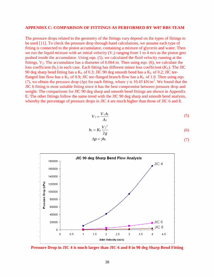
APPENDIX C: COMPARISON OF FITTINGS AS PERFORMED BY W07 RBS TEAM
The pressure drops related to the geometry of the fittings vary depend on the types of fittings to
be used [11]. To check the pressure drop through hand calculations, we assume each type of
fitting is connected to the piston accumulator, containing a mixture of glycerin and water. Then
we run the liquid mixture with an initial velocity (V1) ranging from 1 to 4 m/s as the piston gets
pushed inside the accumulator. Using eqn. (5), we calculated the fluid velocity running at the
fittings, V2. The accumulator has a diameter of 0.064 m. Then using eqn. (6), we calculate the
loss coefficient (hL) in each case. Each fitting has different minor loss coefficient (KL). The JIC
90 deg sharp bend fitting has a KL of 0.3; JIC 90 deg smooth bend has a KL of 0.2; JIC tee-
flanged line flow has a KL of 0.9; JIC tee-flanged branch flow has a KL of 1.0. Then using eqn.
(7), we obtain the pressure drop (∆p) for each fitting, where γ is 10.45 kN/m3. We found that the
JIC 6 fitting is most suitable fitting since it has the best compromise between pressure drop and
weight. The comparisons for JIC 90 deg sharp and smooth bend fittings are shown in Appendix
E. The other fittings follow the same trend with the JIC 90 deg sharp and smooth bend analysis,
whereby the percentage of pressure drops in JIC 4 are much higher than those of JIC 6 and 8.
(5)
(6)
(7)
Pressure Drop in JIC 4 is much larger than JIC 6 and 8 in 90 deg Sharp Bend Fitting
2
112
A
AVV
g
VKh LL
2
22
Lhp

39
Pressure Drop in JIC 4 is much larger than JIC 6 and 8 in 90 deg Smooth Bend Fitting

40
APPENDIX D: DIMENSIONED DRAWING OF REAR HUB
41
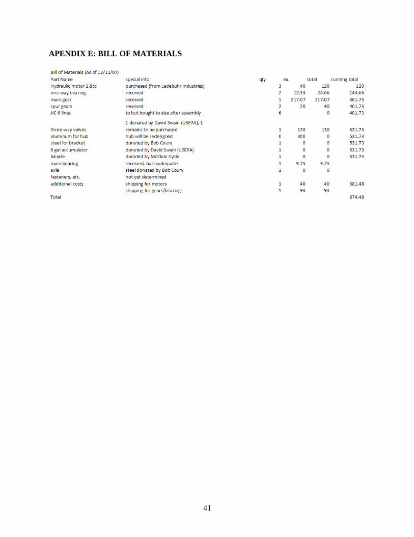
APENDIX E: BILL OF MATERIALS
42
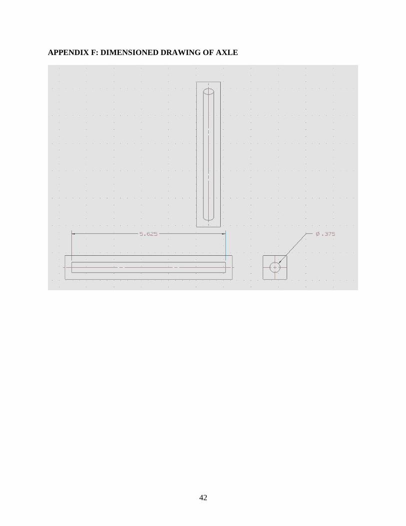
APPENDIX F: DIMENSIONED DRAWING OF AXLE

43
APPENDIX G: DIMENSIONED DRAWING OF HYDRAULIC MOTOR

44
APPENDIX H: Dimensioned Drawing of Bracket
45
APPENDIX I: Finite Element Analysis of Hub
F = 200 lbs