final report magnetic levitation control - aalto
TRANSCRIPT

Aalto University, School of Electrical Engineering Automation and Electrical Engineering (AEE) Master's Programme ELEC-E8002 & ELEC-E8003 Project work course Year 2017
Final Report
Project #26 Magnetic Levitation Control
Date: 28.05.2017
Max Hämäläinen Aapo Ristiluoma Oleg Stikhin Reza Hosseinzadeh Ville Niiranen
Page 1 of 19

Information page Students Max Hämäläinen Aapo Ristiluoma Oleg Stikhin Reza Hosseinzadeh Ville Niiranen Project manager Oleg Stikhin Official instructor Maksim Sokolov Other advisors F Mahafugur Rahman Hafiz Asad Ali Starting date 5.1.2017 Approval The instructor has accepted the final version of this document Date: 28.05.2017
Page 2 of 19

Abstract
The project was to design a controller for a magnetic coil that can levitate a permanent magnet or steel ball in the air. It started by planning the different phases over the upcoming months. Then, some hardware parts such as the magnetic coil and the electronic circuit for supplying the coil, to produce the electromagnetic force were designed. During this period each group member was able to use his theoretical knowledge and apply it to practical matters to better understand the underlying phenomena behind magnetic materials and electronic circuits. To analyze different aspects of the system such as electrical and mechanical dynamics the magnetic levitation system was modeled using Simulink. The simulation results had a significant effect on the designing of the actual controller, as the behaviour of the system became evident at this time. Afterward, a prototype using Arduino MCU was developed to examine the system behavior before implementing the controller in the X2C. The final version of the system then prepared by assembling the electronics, implementing the control algorithm using the X2C for code generation and tuning the controller. During the project, we dealt with a lot of obstacles such as software and hardware incompatibility, the intrinsic nonlinearity of the coil force, etc. Critical thinking and proactivity were among some of the skills that were acquired by group members in the process of working on the project.
Page 3 of 19

Table of Contents Introduction 5
Objective 5
Project plan 5
Simulation 6
Modeling 6
Simulation results 7
Software 8
Development environment 8
Keil µVision 8
Scilab and Xcos 8
X2C 8
Git 8
Microcontroller configuration 8
Control software 9
Hardware 11
Arduino prototype 11
Stand 12
Electronics 13
Control approach discussion 15
Factors affecting the controller and the system 15
Electrical dynamics 15
Mechanical dynamics 15
PWM effect 15
Delays 15
Force production nonlinearity with respect to the air gap 15
Future improvements 16
Hardware improvements 16
Software improvements 17
Reflection of the Project 17
Reaching objective 17
Timetable 17
Risk analysis 17
Project Meetings 17
Quality management 17
Discussion and Conclusions 18
Page 4 of 19

1. Introduction Magnetic levitation is currently under active research, and has a high number of applications. In electric drives, magnetic levitation is used for active magnetic bearings and bearingless machines. In magnetic bearings, the rotating shaft is levitated with electromagnets resulting in very low friction and no mechanical wear. Another application is Maglev (derived from magnetic levitation) which is a transport method that uses magnetic levitation to move vehicles without making contact with the ground. With maglev, a vehicle travels along a guideway using magnets to create both lift and propulsion, thereby reducing friction to a great extent and allowing very high speeds. A project like this is also a good opportunity to test different kinds of tools. The Electric Drives research group has interest in trying out SciLab and X2C for embedded code generation which are both open-source software. SciLab can be used to develop control algorithms and X2C to implement the control to the microcontroller. Using these tools in the project is cost wise and provides useful information about the open-source software. The simple magnetic levitation control system proposed in this project has similarities to the levitation control in active magnetic bearings and bearingless machines. Thus, this project could be used for education and research purposes. For example, creating the control algorithms for a levitation system could be a very exciting and satisfying laboratory exercise.
2. Objective The objective of the project was to build a magnetic levitation system so that a magnetic object could be levitated in a controlled manner. Stable levitation of the object was one of the main goals of the project. Another goal was to develop control software using only open-source software such as SciLab and X2C. The project also has aimed to develop some control system which lets the user to adjust the position of the levitated object in relation to the coil.
3. Project plan The project was to be divided into 9 phases, according to Table 1.
Table 1. Phases of the project plan
Activity Deadline
M1 Project plan 26.1.2017
M2 Familiarizing with Scilab and X2C software 1.2.2017
M3 Hardware prototype ready for software development
1.3.2017
M4 A simple working control loop implemented 14.3.2017
M5 Hardware design finished 1.4.2017
Page 5 of 19

M6 Software is in a presentable state 1.5.2017
M7 Final poster design 9.5.2017
M8 Final gala presentation 16.5.2017
M9 Final report 29.5.2017
The project plan has also described the cost plan, work resources, personal goals of the participants, as well as the jointly agreed formal rules, such as the order of the project meetings, the communication plan, and the quality plan. The project plan can be found in Appendix 2.
4. Simulation
4.1. Modeling Dynamic model of the system [1,2] was implemented using Matlab/Simulink. The equation of motion of the object is
where 𝑚 is the mass of the levitated object, 𝑦 ≥ 0 is the vertical (downward) position of the object measured from a reference point (𝑦=0), 𝑔 is the acceleration due to gravity, 𝐹(𝑦,𝑖) is the force generated by the electromagnet, and 𝑖 is the electric current. Electrical dynamics are modeled with the following equation
The inductance of the electromagnet depends on the position of the levitated object and can be modelled as
where 𝐿 1, 𝐿 0 and 𝑎 are positive constants. With 𝐸(𝑦,𝑖) as the energy stored in the electromagnet, the force 𝐹(𝑦,𝑖) is given by
The system is nonlinear with respect to the air gap (fig. 3b). Thus, a PID controller can only
Page 6 of 19

stabilize the system in the vicinity of one operating point. Feedback linearization is required for stable reference tracking. Current model does not take into account the effect of delays and measurement noise.
Figure 1. Block diagram of the system
The block diagram of the system is presented in the figure 1. This block diagram corresponds to blocks in the Simulink model.
4.2. Simulation results The modeled system in Simulink was simulated by a stepwise change in the position of the magnet at the time = 0.5 s, from a reference value of 5 mm to 6 mm. As it can be seen from the figure 2, although there is some overshoot in the system response, the system reaches stability after 0.4 sec.
Figure 2. Simulation result
In the presented figure, the control system consists of one empirically tuned PID controller and doesn’t take into account the nonlinearity of force production with respect to the airgap, hance the slow response time and the noticeable overshoot after the reference stepwise change.
Page 7 of 19

5. Software
5.1. Development environment The next few subchapters describe the software, that was used in this project.
5.1.1. Keil µVision
μVision provided by Keil is a free integrated development environment used in the project. μVision IDE was selected because it has really good STM32 microcontroller support including software flash tool and online program debugger. IDE also provides advanced source code editor and built-in C/C++ compiler for ARM devices which made setting up software development environment simpler. Although μVision is free software, it is not open-source. It might have been possible to find suitable open-source tools for flashing and debugging STM32 microcontroller, but that would have required use of multiple software instead of one advanced IDE like Keil μVision.
5.1.2. Scilab and Xcos
Scilab is a free and open-source software for numerical computation. Scilab is mainly developed by Scilab Enterprises, but its source code is held in Git repository which can be accessed by anyone. One of the major advantages of Scilab is its third-party support. Along with being open-source third-party support was one of the main reasons why it was used in the project. Xcos is a graphical editor, and part of Scilab used for modeling and simulating dynamical systems. Control system for the microcontroller was developed with Xcos.
5.1.3. X2C
X2C is a free and open source third-party tool for Scilab. It is used for model-based development and code generation of real time control algorithms for microprocessor units. X2C adds new block library to Xcos and graphical control models created using this library can be transformed to C code which is executable on STM32 microcontroller.
5.1.4. Git
Git is an open-source version control system created by Linus Torvalds, creator of the Linux Kernel. Git was used in the project to keep track of software source code changes. Project’s source code repository was hosted on Aalto Version Control System (https://version.aalto.fi) which is a service for software development in Aalto University.
5.2. Microcontroller configuration
STM32F0 microcontroller was selected to the project because it is well supported by X2C tool. Before actual control algorithm implementation microcontroller had to be configured. First step to start configuring microcontroller was to create C++ software project using Keil μVision. Software project consist of four main parts: STM32 standard peripheral libraries, microcontroller configuration files, X2C libraries and control algorithm files. STM32 standard peripheral libraries were used to configure microcontroller I/O pins,
Page 8 of 19

analog-to-digital converters, software interrupts, serial data communication and software timers. These configurations are implemented to microcontroller configuration files. Control algorithm files are files generated by X2C tool and were not modified manually. These files have graphical control model transformed to C code. Implementations of control blocks can be found from X2C libraries. As mentioned earlier Keil μVision IDE has built-in flash tool and online debugger. With these compiled software can be flashed to microcontroller and debugged if needed. Debugger turned out to be useful tool to hunt down software bugs and checking if data acquired from ADCs was reasonable.
5.3. Control software
Control model was developed using X2C libraries in Xcos. Figure 3 illustrates the steps of how graphical Xcos/X2C model (Figure 4) can be used with STM32 microcontroller. First step is to convert model to C code using X2C. After that C code model input and output ports, which usually are variable pointers, have to be connected to microcontroller I/O. This means for example connecting analog signal value received from the ADC to model input port. Connecting ports step has to be done only when new input or output port is added to a graphical model. Next step is to compile software project and flash it to microcontroller. After successful flash program can be observed in two ways: First, using Keil μVision debugger for online debugging with possibility to check variable values and inserting breakpoints. Second, connecting to model using serial data communication between microcontroller and X2C. This allows user to change control parameters like PID controller gains or monitor input and output port signals.
Page 9 of 19
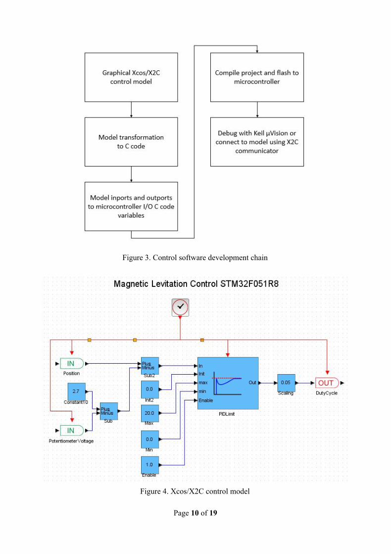
Figure 3. Control software development chain
Figure 4. Xcos/X2C control model
Page 10 of 19

The block diagram of the control system is presented in Figure 4. The PID-controller is implemented with a ready-made control block from X2C. In addition to setting the PID-constants, the control block allows setting minimum and maximum output values and a cutoff frequency for a low-pass filter on the D-term.
6. Hardware
6.1. Arduino prototype Even though the final project was meant to be implemented with the STM32F0-microcontroller, the first prototype of the magnetic levitation control system was made using an Arduino microcontroller. This seemed like a logical step in the project since all group members were at least somewhat familiar with the Arduino but not with the STM32. Building the prototype started with winding the coil. The first coil that was built had a relatively large iron core and had about 1000 turns with 0.3 mm wire. The second coil was made with 0.63 mm wire and had about 1000 turns. It was wound around an empty plastic solder spool and covered with tape to prevent it from unwinding. At this point, the second coil was tested with a core made of thin iron sheets. However, there was a problem since the iron core attracts the magnet that is supposed to be levitated and they would get stuck into each other once getting too close. Therefore, the coil was also tested without the iron core, and it was noticed that the force produced by the coil is enough to lift the magnet from a distance of a few centimeters. Due to this, a decision was made that the project would be completed using the second coil without the iron core.
Next step of making the Arduino prototype was building the output electronics for controlling the current flowing through the coil. The electronics consisted of a transistor, two hall sensors, jumper wires and a few resistors and were connected using a breadboard. The basic idea behind this setup was to determine the relative distance of the magnet by reading the output voltages of the Hall-sensors with the Arduino. The Arduino then adjusts the coil current using the transistor.
Figure 5. Arduino prototype.
The first somewhat successful levitation was achieved by using so-called relay control. The
Page 11 of 19

Arduino was simply used for switching between on- and off-state of the transistor based on the output value of the Hall-sensor. This control method was unstable and the maximum levitation time achieved was less than 10 seconds until the increasing amplitude of the oscillations caused the levitation to fail. After implementing the relay control, it was clear that there was a need for damping in the system to achieve stable levitation. The logical next step was to implement a PID-controller and use pulse width modulation (PWM) for controlling the coil current without any changes to the hardware. The idea was to use the PID controller to adjust the duty cycle of the output pin of the Arduino connected to the transistor. Implementing the PID controller required a complete rewrite of the Arduino code and finding the right gains for the PID. After some time-consuming trial and error tuning, working gains were found, and stable levitation was achieved. At this point, the development with the Arduino was done, and the work continued with STM32F0.
6.2. Stand The aim was to build a simple stand for the system in which all main components of the system are visible. Transparent polycarbonate was selected for the main material since it can be easily cut and bent with a press. The thickness of the top and bottom plate is 5mm. The coil is placed on the top plate and is held there due to its weight. The microcontroller is attached to the bottom plate with short standoff screws. The potentiometer and the power switch are attached to a thinner vertical plate placed on the front of the stand to make them easily accessible. One challenge in the stand design was to make it interfere with the levitation process as little as possible. During the testing phase of the levitation system, it was found that even a small amount of ferromagnetic material near the coil interferes with the levitating magnet thus making controlling it harder. Therefore, standoff insulators were used with nylon nuts to lift the plate holding the coil from the bottom plate.
Figure 6. Unfinished stand.
Page 12 of 19

6.3. Electronics The electronics of the system were kept simple. At the heart of the electronics is an STM32F0 Discovery microcontroller board. The microcontroller runs the control algorithm and interfaces with the control electronics. The electronics were soldered onto a perfboard the size of the microcontroller board. Pin headers were soldered on the perfboard to provide easy connection with the microcontroller board pins. The final board can easily be attached and removed from the perfboard without connecting any wires. The functional diagram of the electronics is presented in figure 7 below and the schematic of the system is presented Appendix 1.
Figure 7. Functional diagram of the electronics
The whole system is supplied from a 24V DC power supply. The coil operates on 24V, the Hall sensors on 5V and the microcontroller on 3.3V. To step the voltage down for electronics, a linear voltage regulator is used. The regulator outputs 5V which is supplied to the Hall sensors and the microcontroller board. The microcontroller board has a separate regulator which steps the 5V to 3.3V for it.
The current flow to the coil is controlled with a single N-type MOSFET. The MOSFET is turned rapidly on and off with a pulse-width modulated signal coming from the microcontroller. To prevent overvoltages when turning the MOSFET off, a freewheeling diode was connected in parallel with the coil. The system has several inputs that provide feedback. Two Hall sensors are used to measure the strength of the magnetic field above and below the coil. Two Hall sensors on both ends of the coil are used to be able to subtract the effect of the coil in the measurements. The Hall sensors output 2.5V when the field is zero, and it goes down to 0V or up to 5V depending on the direction of the field. Since our microcontroller operates on 3.3V and can’t measure voltages higher than that, we are using the 0V-2.5V range as we only need to measure field strength in one direction.
Page 13 of 19
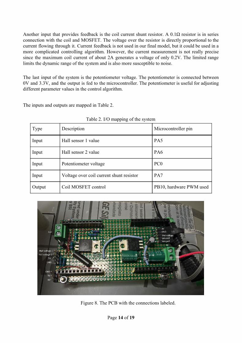
Another input that provides feedback is the coil current shunt resistor. A 0.1Ω resistor is in series connection with the coil and MOSFET. The voltage over the resistor is directly proportional to the current flowing through it. Current feedback is not used in our final model, but it could be used in a more complicated controlling algorithm. However, the current measurement is not really precise since the maximum coil current of about 2A generates a voltage of only 0.2V. The limited range limits the dynamic range of the system and is also more susceptible to noise. The last input of the system is the potentiometer voltage. The potentiometer is connected between 0V and 3.3V, and the output is fed to the microcontroller. The potentiometer is useful for adjusting different parameter values in the control algorithm.
The inputs and outputs are mapped in Table 2.
Table 2. I/O mapping of the system
Type Description Microcontroller pin
Input Hall sensor 1 value PA5
Input Hall sensor 2 value PA6
Input Potentiometer voltage PC0
Input Voltage over coil current shunt resistor PA7
Output Coil MOSFET control PB10, hardware PWM used
Figure 8. The PCB with the connections labeled.
Page 14 of 19

7. Control approach discussion
7.1. Factors affecting the controller and the system
7.1.1. Electrical dynamics In our system, the coil acts as an LR circuit, and its dynamics are presented below,
any changes in the air gap would require the current value to be adjusted and since the coil is fed with voltage and considering the time constant ( ) of the circuit the larger the inductance τ = L
R value, the higher the time constant and as a result, the longer it takes to reach steady-state current. As it was mentioned in the modeling section the inductance changes with any change in the air gap so this also should be considered to have a stable and fast system.
7.1.2. Mechanical dynamics Mechanical dynamics are as below
it is evident that there is a nonlinearity which will be discussed in more detail in the section 7.1.5.
7.1.3. PWM effect The coil is supplied with a PWM voltage which causes additional nonlinearity and inherent delay. Fast switching of high currents can also cause electromagnetic interferences (EMI) and could adversely affect the measurement of the hall sensors.
7.1.4. Delays In control systems delays can cause instability. In the magnetic levitation system, there are some sources of delay such as filter delays from Hall sensors, calculation and I/O delays from the microcontroller. These time delays should be taken into account to have a more stable system.
7.1.5. Force production nonlinearity with respect to the air gap In the figure 9 the coil force and gravity force as a function of airgap are presented. It is clear that the coil force is highly nonlinear and for the coil to be able to produce the required force, appropriate linearization technique has to be implemented.
Page 15 of 19

Figure 9. Coil and gravity force as a function of the air gap
7.2. Control system considerations The electrical dynamics were neglected in the present state of the project. The output of the controller was voltage, that was scaled to the current by dividing with the resistance of the coil - as if the current response was instantaneous. This is a possible assumption, as the mechanical time constant is much larger than the electrical time constant. The mechanical dynamics of the system were controlled by a PID controller. As the system is nonlinear, the PID controller can only provide stability at one operating point, so linearization in the feedback signal from the Hall sensors was done. The electromagnetic force is inversely proportional to the second power of the airgap, as shown in the Modeling section. Using this information, the values from the Hall sensors were translated to values relative to the position of the magnet. Regarding the other effects such as PWM effect and delays, they were neglected in the process of designing and tuning the controller as they did not cause significant issues.
7.2. Future improvements
7.2.1. Hardware improvements ● Faster microcontroller with less internal delay would be a feasible approach in making the
system more stable, ● Using an H-bridge to control the coil. An H-bridge would be able to reverse the voltage
Page 16 of 19

input of the coil, and it could make the system more responsive and allow to generate repulsion forces.
7.2.2. Software improvements ● Designing a current controller ● Parameter identification for modeling and control ● Sensorless methods for estimating the air gap by using a state observer ● Using fixed point numbers in calculations instead of floating point numbers to make
calculations run faster. ● Writing the control software completely in C-code to achieve better performance
8. Reflection of the Project
8.1. Reaching objective The project was completed according to the task description on time before the final gala. Due to some technical problems both from hardware and software side, some adjustments were imminent, but we managed to deal with those issues, and the project was completely ready for the gala.
8.2. Timetable
There were some issues to go forward according to the timetable, but it is something normal that can happen in any project. Regarding the workload, the software part and tuning the controller was a little more time-consuming than what was anticipated.
8.3. Risk analysis
Some of the risks with the software realized, such as getting the software to work with the microcontroller. However, we did not expect that there would be so little documentation for X2C and Scilab. It was challenging to figure out software operation without proper documentation, but we managed to get it to work. We had to ask a few clarifying questions from the X2C software developer via email to clear some issues we had with the software.
8.4. Project Meetings
The project meetings were held 3 or 4 times per month. There were some online meetings such as using Skype and Google Docs chat. For daily communication, we have used a WhatsApp group. The meetings were held both with and without the instructor. We did not prepare the formal agendas, instead we usually devoted each meeting to a single major topic to discuss, of which we informed the instructor. We did not write memos of the meetings, but we tried to document our development process by uploading pictures and writing important information down to our cloud drive. Each official project meeting (i.e., with the instructor) took ca. 1 hour.
8.5. Quality management According to our project plan, the project manager was the main person responsible for quality. He oversees the quality of the project as a whole, while the work package leaders control the quality of their packages more specifically, and report their observations to the project manager. The quality of the work done, and any problems or flaws were controlled and discussed during the project
Page 17 of 19

meetings. Also according to the project plan, the instructor also has played an important role in controlling the quality by providing minimum quality requirements and ensuring that they are fulfilled. Any member of the group noticing a problem or a flaw has indeed immediately informed the group about it. Thus, the quality management has been followed according to the project plan.
9. Discussion and Conclusions
As most of the group members have not had any previous experience in analyzing a project from the business aspects, after completing this we all gained some invaluable knowledge regarding business aspects of a project. A documented report of it is provided in Appendix 3. Furthermore, we developed skills such as critical thinking, personal organization, group work and proactivity throughout various phases of the project. In conclusion, we can say that we have succeeded with the project. Both the main objective and the minor goals have been completed correctly, and in time. Hopefully, the result of this project would contribute to future research in this field.
List of Appendixes 1. PCB schematic 2. Project plan 3. Business aspects document 4. Setting up software development environment for STM32 microcontroller 5. Control program source codes
References 1. Woodson, H. and Melcher, J. (1968). Electromechanical dynamics. 1st ed. University of
Michigan: Wiley 2. Khalil, H. (1996). Nonlinear systems. 2nd ed. Upper Saddle River, New Jersey: Prentice
Hall.
Page 18 of 19

Appendix 1: PCB schematic
Page 19 of 19