final report geological survey for the improvement …
TRANSCRIPT

July, 2017
GEORGE B. PADILLA & Associates Civil/Geotechnical Engineers
9 Sparrow St., Francisville, Mambugan, AntipoloCity 1870, PHILIPPINES Tel./FAX (+632) 6467367 e-mail address: [email protected]
FINAL REPORT GEOLOGICAL SURVEY
FOR THE IMPROVEMENT OF FLOOD FORECASTING AND WARNING SYSTEM
FOR THE CAGAYAN DE ORO RIVER BASIN
VOLUME 1. MAIN REPORT
Prepared for:
NIPPON KOEI CO., LTD
Consultants/Client

Final Report: Geological Survey for the Improvement of Flood Forecasting and Warning System
for the Cagayan de Oro River Basin
GEORGE B. PADILLA & Associates
TABLE OF CONTENTS
VOLUME 1. MAIN REPORT 1 INTRODUCTION ................................................................................... 1 1.1 Authorization ................................................................................... 1 1.2 Report Presentation ........................................................................ 1 2 PURPOSE AND SCOPE OF WORKS ................................................... 2 3 GEOLOGICAL SETTING ....................................................................... 2 3.1 Regional Geology ................................................................................. 2 3.2 Local Geology ........................................................................................ 3 4 GEOTECHNICAL INVESTIGATION PROCEDURES
4.1 Soil Borings ................................................................................ 4 4.2 Laboratory Testing of Borehole Samples ..................................... 5 4.3 Test Pits for Water Level Gauge and Rain Gauge ....................... 6 4.4 Test Pits and Laboratory Tests for Access roads to Site 16B,
Libona ......................................................................................... 7 5 DISCUSSIONS AND RECOMMENDATIONS
5.1 Analysis Inputs and Methodology 5.1.1 Design Soil Profile and Properties at Boreholes .......................... 8 5.1.2 Liquefaction ................................................................................. 8 5.1.3 Types of Foundation .................................................................... 9 5.1.4 Bearing Capacity of Spread Foundations .................................... 9 5.1.5 Analysis of Piles .......................................................................... 10 5.1.6 Factor of Safety (F.S.) ................................................................. 10 5.2 MPRSD-PAG-ASA ...................................................................... 11 5.2.1 Subsurface Conditions and DesignSoil Profile ............................. 11 5.2.2 Liquefaction Potential of MPRSD ................................................ 11 5.2.3 Pile Foundation for MPRSD ........................................................ 12 5.3 RW-2 at Pelaez Bridge, Cagayan de Oro City 5.3.1 Subsurface Conditions and DesignSoil Profile ............................. 12 5.3.2 Liquefaction Potential at RW-2 .................................................... 12 5.3.3 Pile Foundation for RW-2 ............................................................ 12 5.4 XR-1 Site 16B, Libona ................................................................. 13 5.4.1 Subsurfac Conditions and Design Soil Profile at XR-1 ................. 13 5.4.2 Spread Foundation at XR-1 ......................................................... 13

Final Report: Geological Survey for the Improvement of Flood Forecasting and Warning System
for the Cagayan de Oro River Basin
GEORGE B. PADILLA & Associates
5.5 XR-2 Dagumbaan Integrated School, Talakag 5.5.1 Subsurface Conditions and DesignSoil Profil at XR-2 .................. 14 5.5.2 Liquefaction Potential at XR-2 ..................................................... 14 5.5.3 Pile Foundation for XR-2 ............................................................. 14 5.6 Telemeter Houses: Summary of Observations and
Recommendations ...................................................................... 15 5.7 Approach Roads at Site 16B Libona ............................................ 16 5.7.1 CBR Values ................................................................................. 16 5.8 Site Seismic Factors and Coefficients ......................................... 17
6 GENERAL REMARKS ........................................................................... 18 REFERENCES FIGURES Figure 1a. General Location Map Figure 1b. List of Site Locations Figure 2. Topographic Map and Location of TestPits at Site 16B Libona,
Proposed Access Roads Figure3 Geology and Tectonic Map of Project Area Figure 4 Maximum Ground Acceleration Figure 5a. Fault Map for MPRSD Figure 5b. Fault Map for RW-2 Figure 5c. Fault Map for XR-1 Figure 5d. Fault Map for XR-2 ATTACHMENTS A. Symbols B. MPRSD LIQUEFACTION AND PILE ANALYSIS
B1. Design Soil Profile for MPRSD B2 Liquefaction Analysis - MPRSD B3. Analysis of Piles at MPRSD - Normal Condition B4. Design Soil Profile for MPRSD - Liquefaction Condition B5 Analysis of Piles at MPRSD - Liquefaction Condition

Final Report: Geological Survey for the Improvement of Flood Forecasting and Warning System
for the Cagayan de Oro River Basin
GEORGE B. PADILLA & Associates
C. RW-2 LIQUEFACTION AND PILE ANALYSIS
C1. Design Soil Profile at RW-2 C2. Liquefaction Analysis - RW-2 C3. Design Soil Profile for RW-2 - Liquefaction Condition C4 Analysis of Piles at RW-2 - Normal Condition C5 Analysis of Piles at RW-2 - Liquefaction Condition
D. XR-1 SPREAD FOOTING ANALYSIS
D1. Design Soil Profile at XR-1 D2. Bearing Capacity Analysis
E. XR-2 LIQUEFACTION AND PILE ANALYSIS
E1. Design Soil Profile at XR-2 E2. Liquefaction Analysis - XR-2 E3. Design Soil Profile for XR-2 - Liquefaction Condition E4 Analysis of Piles at XR-2 - Normal Condition E5 Analysis of Piles at XR-2- Liquefaction Condition
F BEARING CAPACITY ANALYSIS OF SPREAD FOOTINGS F1. R-8
F2 R-9 F3 R-10 F4 R-11 F5- R-12 F6 R-13

Final Report: Geological Survey for the Improvement of Flood Forecasting and Warning System
for the Cagayan de Oro River Basin
GEORGE B. PADILLA & Associates
VOLUME 2. APPENDICES A. Final Borehole Logs and Summary of Test Results, Photos of Site
Laboratory Tests: Natural moisture content, Atterberg Limits, Sieve analysis, Specific Gravity, Direct Shear Test.
Appendix No.
Borehhole No.
A1 MPRSD
A2 RW-2
A3 XR-1
A4 XR-2
B. Test Pit Logs and Summary of Test Results and Photos of Site
Laboratory Tests: Natural moisture Content, Atterberg Limits, Sieve Analysis, Specific Gravity, Direct Shear Test
Test Pit No.
RW-1
RW-2
RW-3
RW-4
RW-5
RW-7
R-8
R-9
R-10
R-11
R-12
R-13
C. Test Pit Logs for Approach Road at Libona and Photos of Site
Laboratory Tests: Natural moisture content, Atterberg limits. Sieve Analysis, Specific Gravity, Compaction Test, CBR Test
Test Pit No.
TP-1
TP-2
TP-3
TP-4

Final Report: Geological Survey for the Improvement of Flood Forecasting and Warning System
for the Cagayan de Oro River Basin
GEORGE B. PADILLA & Associates Page 1
1 INTRODUCTION
1.1 Authorization
Presented in this report are the results of the geological survey conducted
in connection with the Preparatory Survey for the Improvement of Flood
Forecasting and Warning System for the Cagayan de Oro River Basin.
This work is covered in the contract entered into by and between NIPPON
KOIE CO., Ltd. (the Client/Consultants) and GEORGE B. PADILLA &
Associates (the Contractor).
This report consolidates the earlier submittals of the Contractor to the
Client and completes the works stipulated in the Contract.
1.2 Report Presentation
For convenience, this report is presented in two volumes whose contents
are as follows:
Volume 1. MAIN REPORT: contains background information on the
project, investigation program and procedures, subsurface conditions at
borehole and test pit locations, discussions and recommendations.
Each site is analyzed based on the findings from boreholes or test pits.
Attached to this volume are various maps and analysis works sheets..
Volume 2. TEST RESULTS: This is the Appendix to the Main Report and
contains the final borehole and test pit logs and the laboratory test results.
The field data and laboratory test results, including photos, at each test
pit or borehole are grouped together.
Complete Table of Contents are provided in each volume.
For brevity and convenience, the Project is also referred to as CDOR-
FFWS in the succeeding sections of this report.

Final Report: Geological Survey for the Improvement of Flood Forecasting and Warning System
for the Cagayan de Oro River Basin
GEORGE B. PADILLA & Associates Page 2
2 PURPOSE AND SCOPE OF WORKS
This Geological Survey forms part of the Project for the Improvement of Flood
Forecasting and Warning System in Cagayan River Basin. The Project
consists of various structures within the Cagayan de Oro River Basin. To
design these structures subsurface data and related information are required
for the design of foundations, pavements, identification of sources of borrow
materials for construction, and determination of parameters for analysis of
structures, including geo-hazards particularly liquefaction.
As per Technical Specifications issued by the Client subsurface data
collection by soil borings and test pits were carriedour at specified locations.
These are indicated in the General Location Plan in Figure 1a with the
corresponding list of site locations are in Figure 1b.
Additional Works consisting of Test Pits for purposes of determining the CBR
of subgrade soils at proposed Access Roads Roads in Libona Site 16B were
also carried out (refer to Figure 2).
3.0 GEOLOGIC SETTING
3.1 Regional Geology
Based on the geologic of map from the Mines and Geosciences Bureau, in
the broader physiographic framework of the Philippine archipelago, Region 10
occupies the northern portion of the Central Mindanao. The Central Mindanao
is bounded by two(2) major structures that played a key tectonic role in the
tectonic evolution of the Philippine Mobile Belt, namely the Philippine Trench
and the Philippine Fault Zone.
The geologic evolution of the Central Mindanao was largely controlled by
convergent and transform tectonics intermittently active during Upper
Cretaceous to Pleistocene time and the volcanic activity. These complex
tectonic processes brought about the multiple stage island arc volcano-
sedimentary sequences. The broad geomorphic configuration of the region is
largely controlled by these tectonic processes of the past.
The oldest rocks in the region are the pre-Tertiary metamorphic and ophiolitic
suite of rocks of Cretaceous age. Exposures of post-ophiolitic sedimentary
rocks of Eocene age suggest dominant erosional processed from Paleocene
to Eocene period. On the other hand, the Oligocene to Middle Miocene age is
Final Report: Geological Survey for the Improvement of Flood Forecasting and Warning System
for the Cagayan de Oro River Basin
GEORGE B. PADILLA & Associates Page 3
marked by thick accumulation of arc basaltic volcano sedimentary sequence
and turbidites later succeeded by middle-Miocene to Pliocene volcanic flows,
pyroclastic and epiclastic of more andesitic composition.
Arc magmatism was also active during the middle Miocene to Pliocene times
generation monzonitic and dioritic stocks and plutons and hornblende
andesites. In areas away from paleo-volcanic centers, thick sedimentary
clastic rocks with limestone horizons and calcareous sediments were formed
during the Miocene to Pliocene. Reefal limestone unconformably capped
older rocks with age assignment ranging from Miocene to Plio-Pleistocene.
The Cagayan Gravel represents the latest quaternary deposits in the region.
3.2 Local Geology
The project area is situated along the Cagayan River which drains
northeastward to Macajalar Bay. The area is characterized by gentle to
rugged terrain and steep slopes and deeply-incised valleys with elevation
ranges from 20 m to 400 m. The area is bounded by NW-SE trending fault
which are located east from the project area: the Tagoloan River Fault, the
Cabanglasan Fault and the Central Mindanao Fault.
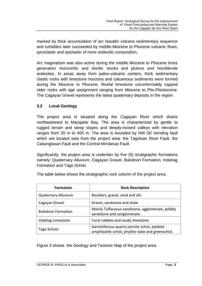
Significantly, the project area is underlain by five (5) stratigraphic formations
namely: Quaternary Alluvium, Cagayan Gravel, Bukidnon Formation, Indahag
Formation and Tago Schist.
The table below shows the stratigraphic rock column of the project area:
Figure 3 shows the Geology and Tectonic Map of the project area.
Formation Rock Description
Quaternary Alluvium Boulders, gravel, sand and silt.
Cagayan Gravel Gravel, sandstone and shale
Bukidnon Formation Mainly Tuffaceous sandstone, agglomerate, pebbly sandstone and conglomerate.
Indahag Limestone Coral rubbles and sandy limestone
Tago Schists Garnetiferous quartz-sericite schist, epidote amphibolite schist, phyllite-slate and greenschist.

Final Report: Geological Survey for the Improvement of Flood Forecasting and Warning System
for the Cagayan de Oro River Basin
GEORGE B. PADILLA & Associates Page 4
4 GEOTECHNICAL INVESTIGATION PROCEDURES
4.1 Soil Borings
Four boreholes, namely: MPRSD, XR-1, XR-2, RW-2 were carried out for the
Project. One borehole RW-1 was deferred.
Two hydraulic fed, rotary drilling rig was employed to advance the borehole, extract soil and core samples, and perform standard penetration test. Basically, a drilling rig consists of a rotary head driven by a13-HP Yanmar diesel engine. This is mounted on a steel frame bolted onto a wooden skid. A mast, consisting of 2” dia. pipe legs, supports a double pulley where a Manila rope and a 3/8” wire rope pass. Lifting of AW drill rods and NW casings, and samplers is done with a motorized cathead. A pressure pump forms part of the drilling equipment. Rotary wash boring technique was used to advance through soil deposits..
Water jets under high pressure is directed through drill rods into the ground by
means of the pressure pump. By means of a chopping tool attached at the tip
of the drill rods the soil is loosened. The cuttings become part of the
suspension that flow under pressure up to the surface and into a settling
basin. The return water is re-circulated but continuous supply of water is
maintained if water is lost in the borehole. The collapsible upper section of
the borehole is stabilized by means of NW steel casings which are driven into
the soil or drilled into rock.
Standard penetration testing (SPT) ASTM D 1586-08 is carried out in soil at depth intervals of not more than 1.0m . The SPT is performed using a standard split-spoon sampler, having 50 mm outside diameter, 35 mm inside diameter and about 710 mm length, which is attached at the bottom of a string of drill rods (see details below). The sampler is driven into the bottom of the borehole. Then it is driven 300 mm further. The number of blows required for each 150 mm of penetration is recorded. The total number of blows for the last 300 mm of penetration is known as the standard penetration resistance (N) of the soil. During the SPT disturbed soil samples are trapped in the split-spoon sampler as it penetrates into the soil. Part of the retrieved soil is placed in moisture-tight plastic bags for further examination and laboratory testing. Undisturbed samples of soft soils (UDS) were extracted using thin walled Shelby tube samplers. Both ends were sealed with wax to prevent disturbance and to preserve natural moisture content.

Final Report: Geological Survey for the Improvement of Flood Forecasting and Warning System
for the Cagayan de Oro River Basin
GEORGE B. PADILLA & Associates Page 5
Penetration through rock as well as hard clay is accomplished by continuous rotary core drilling with NQ size core barrels fitted with tungsten carbide or diamond bits (see details below). The maximum drilling run is 1.5m but shorter runs are made in soft or highly fractured formation to ensure recovery. Rock cores recovered using NQ core bits are about 44mm in diameter. The core samples are placed and arranged in special PVC boxes with appropriate partitions, separators and labels. The water level in each borehole is measured during the drilling period and after the completion of the boreholes. Water level measurements are shown in the boring logs. The results of the SPT, description of the soil and core samples and other field data are recorded in field boring logs. Details of the samplers used are presented in the drawings in the next page.
Field data recorded in field boring logs include the following: sample and
core recovery, solid core recovery, Rock Qualiity Designation(RQD),
description of the samples obtained, and other field observations. These are
presented as Final Borehole Logs and Summary of Test Results in Appendix
B..
4.2 Laboratory Testing of Borehole Samples Selected soil samples from boreholes were subjected to the following laboratory tests:
Standard Test Method for Determination of Water(moisture) Content ASTM D2216 05
Standard Test Methods for Liquid Limit, Plastic limit and Plasticity Index of Soils ASTM D 4318 - 05
Standard Test Method for particle Analysis of Soils Particle Size Analysis of Soils ASTM D 422 -63(2007)
Standard practice for Classification of Soils for Engineering Purposes (Unified Classification System) ASTM D 2487-06
Standard Practice for Determination of the Specific Gravity of Soil Solids ASTM D854-05.
Standard Practice for Direct Shear Test of Soils ASTM D3080-04 All laboratory tests were performed at the Contractor’s field laboratory in Cagayan de Oro City except the UDS which were transported to the main laboratory in Antipolo City.

Final Report: Geological Survey for the Improvement of Flood Forecasting and Warning System
for the Cagayan de Oro River Basin
GEORGE B. PADILLA & Associates Page 6
The final borehole log and laboratory test worksheets for each site are grouped together
4.1 Soil Borings
4.3 Test Pits for Water Level Gauge and Rain Gauge
A total of twelve test pits were excavated to maximum depths of 2.0m or
earlier when boulders are encountered. One of the specified test pits RW-6,
located in LIboran was deferred.

Final Report: Geological Survey for the Improvement of Flood Forecasting and Warning System
for the Cagayan de Oro River Basin
GEORGE B. PADILLA & Associates Page 7
Undisturbed samples using steel molds were extracted at the bottom of the
boreholes, except those that are bouldery. Small samples were also collected
at upper depths.
As those of the borehole samples, the test pit samples were subjected to the
same tests including direct shear tests on UDS samples.
The Final Test Pit Logs and Summary of Test Results, including photos of the
sites, and laboratory work sheets are grouped for each site. These are
presented in Appendix B
4.4 Test Pits and Laboratory Tests for Approach Roads I Site 16B,
Libona
Four test pits, 2.0m deep, were carried out at the proposed Access Roads in
Site 16B, Libona (see Fig. 2). These are intended to secure data and obtain
samples for laboratory testing pertinent to design of roads.
Undisturbed samples (UDS) using CBR steel molds were extracted from the
bottom of the test pits. These were brought to the laboratory for CBR
penetration (ASTM D1883) in their natural moisture content conditions.
Composite bulk samples approximately 50kg were collected and placed in
sacks.. These tested for moisture-density relationship as per AASHTO-
T180”D”. CBR tests (ASTM D1883) ) were carried out on compacted samples
under saturated condition.
The Test Pit Logs with Summary of test results and photos of the site,
including laboratory worksheets, are presented in Appendix C.

Final Report: Geological Survey for the Improvement of Flood Forecasting and Warning System
for the Cagayan de Oro River Basin
GEORGE B. PADILLA & Associates Page 8
5 DISCUSSIONS AND RECOMMENDATIONS
5.1 Analysis Inputs and Methodology 5.1.1 Design Soil Profile and Properties at Boreholes This Evaluator defined the various strata comprising the soil profile of boreholes based essentially on soil type and SPT N values. For purposes of foundation analysis and design, relevant soil properties are assigned to each layer. This Evaluator makes use of the software ALLPile (ref. 1) developed for piles and shallow spread footings to obtain the soil parameters enumerated below.
= unit weight, kN/m3
= friction angle, degrees c = cohesion, kN/m2 k = modulus of subgrade reaction, MN/m3
AllPile uses correlations between SPT N Values and soil type to estimate the values of the above parameters. However, the Evaluator also exercised judgment and professional discretion in the selection and application of the values of parameters. 5.1.2 Liquefaction Earthquake effects on soil such as liquefaction and the concomitant transient
lose of strength and permanent settlement often govern the selection of the
type of foundation for structures.
The liquefaction potential of soils depend on their gradation, plasticity, SPT N
value, and the presence of groundwater. The occurrence of liquefaction will
depend on the magnitude of the earthquake and the ground acceleration it
generates.
Loose, submerged, cohesionless sand and silt, and even slightly cohesive
materials are susceptible to liquefaction. Moderately to highly plastic silt and
clay are not liquefiable.
The susceptibility of soils to liquefaction may be assessed from their
gradation. Indicated in the grain size distribution curves in the Appendices are
red two curves which envelope soils from various places worldwide known to
have liquefied.

Final Report: Geological Survey for the Improvement of Flood Forecasting and Warning System
for the Cagayan de Oro River Basin
GEORGE B. PADILLA & Associates Page 9
The liquefaction potential of the sand and silty sand may be evaluated using
correlations and procedures developed by Seed and Idriss (ref. 2) and
improved by later researchers. Basically, the liquefaction evaluation consist of
comparing the cyclic shear stress induced on the subsoils by an earthquake
and the cyclic shear strength of the subsoils. The latter can be determined
either by laboratory cyclic shear test or correlations with the SPT N-value.
The ratio of the shear strength to the shear stress is the factor of safety
against liquefaction which should be within the acceptable range of 1.25 to
1.5.
With the aid of the software LiquefyPro (Ref. 3) the liquefaction potential of
sites during earthquakes of given magnitude and ground acceleration were
calculated and the corresponding ground settlement estimated.
For this study, the following earthquake parameters were used:
Magnitude: 7.0 Maximum ground acceleration: 0.40g (see Figure 4)
Under liquefaction conditions, the design soil properties are altered. For instance the coefficient of subgrade reaction is degraded to 1/10 its normal condition value. 5.1.3 Types of Foundation Both shallow and deep foundations are presented as alternatives, each with associated risk and cost implications. Spread footings are perceived to be the cheapest type of foundation but as discussed in the succeeding section, this may not be the safest choice in areas that are susceptible to liquefaction. There are also construction difficulties associated with spread footings particularly when working below GWL . The foundation alternative would be piles driven past the liquefiable zone and into firm layers. 5.1.4 Bearing Capacity of Spread Foundations Basically, Terzaghi’s equation is used in determining the ultimate bearing capacity qult of spread foundations as follows:
qult = cNc + 0.5BN+ qNq

Final Report: Geological Survey for the Improvement of Flood Forecasting and Warning System
for the Cagayan de Oro River Basin
GEORGE B. PADILLA & Associates Page 10
where,
Parameter Definition Remarks
c cohesion obtained from laboratory tests or from correlations with SPT
q effective stress of soil at foundation base at depth D
q = D
unit weight of soil Obtained from laboratory tests or correlations with SPT
B width or diameter of foundation
Nc, N/2,
Nq
bearing capacity factors
These are functions of the angle of
internal friction of the soil and are also
obtainable from tables1; is obtained
from laboratory tests or correlations with SPT
5.1.5 Analysis of Piles
The geotechnical axial capacity and lateral resistance of piles was determined
with the aid of the software AllPile..The output from this analysis presented in
this report includes:
Foundation Profile and Soil Conditions (the Design Soil Profile)
Allowable Capacity (Compression and Uplift) vs Depth
Lateral Load vs. Deflection & Maximum Moment
For purposes of this exercises, a 350 x 350 precast concrete pile is assumed.
5.1.6 Factor of Safety (FS) The allowable bearing capacity qall is obtained by applying a factor of safety FS on qult. For this project it is recommended to use FS=3.0 on spread footings and piles, primarily to take into account possible variations in soil properties and construction tolerances.

Final Report: Geological Survey for the Improvement of Flood Forecasting and Warning System
for the Cagayan de Oro River Basin
GEORGE B. PADILLA & Associates Page 11
5.2 MPRSD-PAGASA 5.2.1 Subsurface Conditions and Design Soil Profile This site for a 40-m high communication tower is underlain essentially by a thick deposit of marine sediments as evidenced by the presence of shell fragments from near the surface to depth 34.0m. Beyond 34.0 to 40.0m, the soils are alluvial deposits (see Appendix A1.). SPT N values from the surface to depth of 26m are less than 10. From 2.0m to 6.0m, the materials consist of sand and silt which are essentially cohesionless to slightly plastic. As discussed earlier it is this zone which is potentially liquefiable. After 6.0m up to 40.0m, the materials are composed predominantly of silt that are moderately to highly plastic. Between 26m and 34m SPT N values range from 10 to 33 with a single low insertion of 8. From 34.0m to 39.0m SPT N values go down to between 10 and 12. It is also within this zone that shell fragments are absent, fragments of decayed wood were recovered and very high liquid limits ranging from 51 to127 were obtained. SPT refusal was encountered at 40.0m, the target depth. Groundwater level could vary with season but is herein taken as 2.0m below ground surface. The design soil profile for MPRSD is shown in Attachment B1. 5.2.2 Liquefaction Potential of MPRSD-PAGASA A liquefaction analysis using software Liquefy is presented in Attachment B2 which indicates that the zone from 2.0m-6.0m is liquefiable and the expected total settlement due to liquefaction is about 11cm.(see Attachment B2). Under liquefaction condition the design soil profile is presented in Attachment B4.