final report fingerprint based user...
TRANSCRIPT

Final Report Fingerprint Based User Authentication
April 9, 2007
Wade Milton 0284985 Jay Hilliard 0236769
Breanne Stewart 0216185

University of Guelph School of Engineering
1
Table of Contents 1. Executive Summary ...................................................................................................... 3 2. Introduction ................................................................................................................... 4
2.1 Problem Statement .................................................................................................... 4 2.2 Objectives ................................................................................................................. 4 2.3 Constraints ................................................................................................................ 4 2.4 Criteria ...................................................................................................................... 5 2.5 Assumptions .............................................................................................................. 5
3. Background ................................................................................................................... 5 3.1 Fingerprint Biometrics .............................................................................................. 5 3.2 Fingerprint Analysis.................................................................................................. 6
4. Method ........................................................................................................................... 8 4.1 Analysis techniques: ................................................................................................. 8 4.2 Background Segmentation: ....................................................................................... 9 4.3 Contrast Manipulation: ........................................................................................... 10 4.4 Grey-scale Filtering: ............................................................................................... 11 4.5 Binarization: ............................................................................................................ 13 4.6 Thinning: ................................................................................................................. 14 4.7 Binary Filtering: ...................................................................................................... 14
4.7.1 Ladder and Spur Removal ............................................................................... 15 4.7.2 De-Line Function ............................................................................................. 17
4.8 Other Functions ....................................................................................................... 17 4.8.1 Image Smoothing ............................................................................................. 17 4.8.2 Histogram Graphing ......................................................................................... 18 4.8.3 Orientation Estimation ..................................................................................... 18 4.8.4 Median Filter .................................................................................................... 20
5. Results .......................................................................................................................... 20 5.1 Fingerprint Image Pre-Processing........................................................................... 20 5.2 Mean Filtering ......................................................................................................... 20 5.3 Histogram Equalization .......................................................................................... 21 5.4 Wiener Filter ........................................................................................................... 22 5.5 Binarization ............................................................................................................. 23 5.6 Thinning and Morphological Filtering .................................................................... 23 5.7 Fingerprint classification ........................................................................................ 24
6. Discussion..................................................................................................................... 27 7. Conclusions .................................................................................................................. 29 8. Recommendations ....................................................................................................... 30 9. References .................................................................................................................... 32 Appendix .......................................................................................................................... 34
University of Guelph School of Engineering
2
List of Tables Table 1: Classification based on singular points [12]. ...................................................... 26 Table 2: Comparison between different classification methods. ...................................... 27 List of Figures Figure 1: Different fingerprint patterns. (a) arch, (b) tented arch, (c) right loop, (d) left loop, (e) whorl and (f) twin loop [2] ................................................................................... 6 Figure 2: Flow chart for Image pre-processing. .................................................................. 9 Figure 3: Flow chart for a Gabor filter [7]. ....................................................................... 11 Figure 4: Block diagram for Wiener filtering method [8]. ............................................... 12 Figure 5: Filter Mask for Noise Variance Estimation ...................................................... 13 Figure 6 - Flow chart depicting ladder and spur removal logic. ....................................... 16 Figure 7: Sorbel Mask for X-direction Gradient Estimation ............................................ 19 Figure 8: Sorbel Mask for Y-direction Gradient Estimation ............................................ 19 Figure 9: X-gradient Convolution Calculation ................................................................. 19 Figure 10: Y-gradient Convolution Calculation ............................................................... 19 Figure 11: Calculation for the Orientation Estimation in Radians ................................... 19 Figure 12: Original image and its binarization and thinning. ........................................... 20 Figure 13: Mean filtered image and its result on the final thinned image. ....................... 21 Figure 14: Original image's histogram and its histogram after applying the equalization............................................................................................................................................ 22 Figure 15: Image after applying histogram equalization and its effect on the final thinned image. ................................................................................................................................ 22 Figure 16: Image after passing it through the Wiener filter and the effect on the final thinned image. ................................................................................................................... 22 Figure 17: Binarized filtered image. ................................................................................ 23 Figure 18: Thinned image after filtering and binarization. ............................................... 23 Figure 19: Thinned image passed through the point mask filter. ..................................... 24 Figure 20: Final image after passing through the de-lining function. ............................... 24 Figure 21: Poincare index, the rotation of the vector V along the curve Ψ [14]. ............. 25 Figure 22: The Poincare index for each type of singular point [13]. ................................ 26
University of Guelph School of Engineering
3
1. Executive Summary The focus of this project is to look at the problems surrounding fingerprint-based user
authentication. Biometric authentication is more reliable than tradition methods because
it is not knowledge- or possession- based like a password or swipe card that can be
forgotten or lost, it is a part of the person being identified.
Fingerprint analysis starts with image processing which is where the fingerprint is
converted into a form that can be used to classify and extract minutiae. The next step is
classification which is where the fingerprint is distinguished as part of a smaller group of
fingerprint types so that it is not compared to every fingerprint in the database. Finally,
minutia-based fingerprint analysis involves matching the local discontinuities of the
fingerprint. Discontinuities include terminations, also known as ridge endings, and the
bifurcations which is where ridges fork or diverge. The authentication stage validates the
identity of the individual by extracting the pattern of minutiae from the fingerprint and
subjecting it to a matching algorithm in an effort to validate it against one of the
templates stored in the system database.
This project puts emphasis on the image processing stage by giving detailed descriptions
of each step within this segment of fingerprint authentication. It also investigates the
different methods used to produce a final fingerprint skeleton and the algorithms that are
required for each one. Each algorithm’s effect will also be explained with a
demonstration of its results. The recommended fingerprint classification method is to
group the fingerprints into four types; Arch, Right Loop, Left Loop, and Whorl. This is
done by calculating the Poincare index and tracing the original lines.
University of Guelph School of Engineering
4
2. Introduction
2.1 Problem Statement The focus of this project is to look at the issues surrounding fingerprint-based user
authentication. Biometric authentication is the use of physiological characteristics such
as a fingerprint, hand shape, face map, voice, or iris to determine the identification of the
user [1]. This type of identification is more reliable in comparison to traditional
verification methods such as possession of a key or swipe card, or the knowledge of a
password or login, because the person is required to be physically present at the time of
identification [2]. Reliable personal identification is important in everyday transactions
ranging from ATM withdrawals to restricted building access. Biometric identification
could decrease billions of dollars lost every year to credit card fraud, welfare “double-
dipping”, cellular bandwidth thieves, and ATM fraud by providing near irrefutable proof
of identification.
2.2 Objectives
• Investigate the process of fingerprint-based user authentication.
• Create a software package that implements the pre-processing techniques
suggested in the Greenberg et al article [8].
• Provide software tools and information that can be used to facilitate future
research.
• Recommend a method for classification.
2.3 Constraints
• The fingerprint image must be an uncompressed Bitmap, 256 x 256 pixels.
• Fingerprint images must be previously acquired
University of Guelph School of Engineering
5
2.4 Criteria
• Minimize the cost of the design.
• Provide usable solutions to problems for fingerprint-based authentication.
• Algorithms should be as easy to understand as possible and upgradeable.
2.5 Assumptions
• Assume that a fingerprint image is from a real person.
• Assume the supplied fingerprint has no background or noise which requires
segmentation.
3. Background
3.1 Fingerprint Biometrics Biometrics is the science of identifying a person based on physiological characteristics
that distinguishes one person from another [3]. Biometric identification is more reliable
than traditional verification methods because the person is required to be physically
present at the time of identification [2]. These methods may include the possession of a
key or swipe card or the knowledge of a password or login.
All fingerprints are believed to be unique to each person and finger; even twins do not
have the same fingerprints [1]. As well, fingerprints do not change over time. These
characteristics contribute to why the fingerprint is the most widely used biometric trait.
Fingerprint technology is the most developed technology in biometric recognition [3],
and is legitimate proof of evidence in courts of law all over the world [2].
Fingerprint recognition has been used for a significant amount of time. The “Henry
System” was developed in the early 1800’s by Edward Henry to classify and identify
fingerprints based on the ridge configurations and was revamped by the FBI in the early
University of Guelph School of Engineering
6
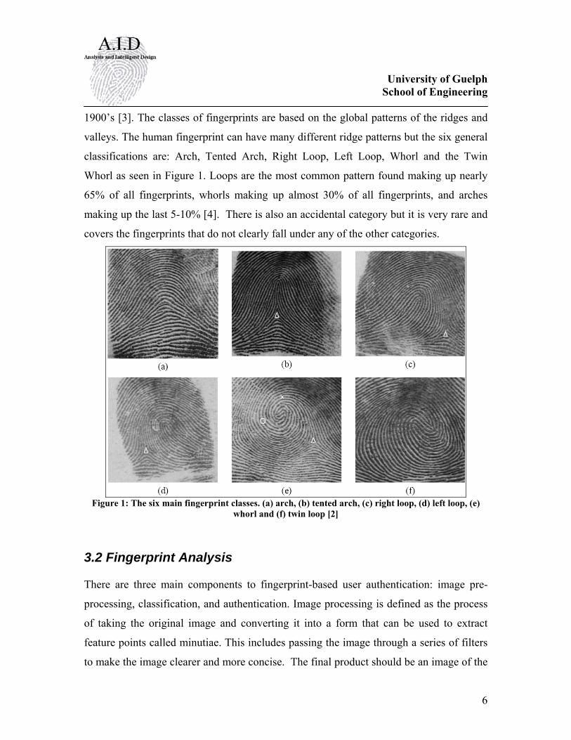
1900’s [3]. The classes of fingerprints are based on the global patterns of the ridges and
valleys. The human fingerprint can have many different ridge patterns but the six general
classifications are: Arch, Tented Arch, Right Loop, Left Loop, Whorl and the Twin
Whorl as seen in Figure 1. Loops are the most common pattern found making up nearly
65% of all fingerprints, whorls making up almost 30% of all fingerprints, and arches
making up the last 5-10% [4]. There is also an accidental category but it is very rare and
covers the fingerprints that do not clearly fall under any of the other categories.
Figure 1: The six main fingerprint classes. (a) arch, (b) tented arch, (c) right loop, (d) left loop, (e)
whorl and (f) twin loop [2]
3.2 Fingerprint Analysis
There are three main components to fingerprint-based user authentication: image pre-
processing, classification, and authentication. Image processing is defined as the process
of taking the original image and converting it into a form that can be used to extract
feature points called minutiae. This includes passing the image through a series of filters
to make the image clearer and more concise. The final product should be an image of the
University of Guelph School of Engineering
7
fingerprint ridges thinned to one pixel without any spurs and bridges remaining. Without
this step the fingerprint cannot be analysed further. Following this is classification where
the fingerprint is distinguished as part of a smaller group of fingerprint types so that it is
not compared to every fingerprint in the database. By only comparing it to similar
fingerprints the amount of time required for processing is drastically reduced. The
authentication stage is the last step where it validates the identity of the individual by
extracting the pattern of minutiae from the fingerprint and subjecting it to a matching
algorithm in an effort to match it against one of the templates stored in the system
database.
The minutiae-based fingerprint matching is a very popular authentication method.
Minutiae-based fingerprint analysis involves matching the local discontinuities or
minutiae of the fingerprint. Discontinuities in a fingerprint include terminations or ridge
endings and the bifurcations where ridges fork or diverge [5]. The information for a
fingerprint is then stored as a point pattern of minutiae instead of a complete image of a
fingerprint [6]. It is also simpler compared to other forms of fingerprint matching such as
ridge-pattern based or complete image based and is faster and has a small template [2].
University of Guelph School of Engineering
8
4. Method
4.1 Analysis techniques: A review of the literature on dealing with fingerprint analysis shows that there are three
steps that are required to implement fingerprint authentication. The first step involves
pre-processing of the fingerprint information so that information can be reliably extracted
from the fingerprint data. The next step is to classify the fingerprint into one of several
sub categories. By classifying fingerprints into sub categories it does not need to be
compared with all the reference fingerprints but, only those in its category. The last step
is then to try and reliably match the fingerprint to one of the stored reference prints.
Within these main steps there is some variety in each approach but all these methods
essentially attempt to produce a similar result. This result in an enhanced fingerprint that
will provide valid information that allows for fingerprints to be matched to previously
sampled information.
It is obvious from our literature review and early attempts to implement some of the
common algorithms suggested in articles centered on fingerprint analysis that the
complete task of fingerprint analysis and matching is far from trivial. For this reason, our
project concentrated on the pre-processing of the grey-scale fingerprint image and to
assign fingerprints to different classes. Fingerprint matching techniques will not be
directly addressed.
The real first step in any fingerprint authentication system is taking a sample of the
fingerprint. This is usually done through the use of a sensor but could be done with
manual techniques. The important detail about sampling a fingerprint is that the
information taken to represent the fingerprint must be converted to a form that can be
manipulated using digital systems. This means that through whatever source that the
University of Guelph School of Engineering
9
fingerprint is taken, the end result is a matrix of pixels that represent the grey-scale ridge
and valley structure of the fingerprint.
The major issue that stem from taking fingerprint samples is the quality of the
information. The quality of the fingerprint will directly affect the system’s ability to
match fingerprint samples and this is the reason that the image needs to be processed
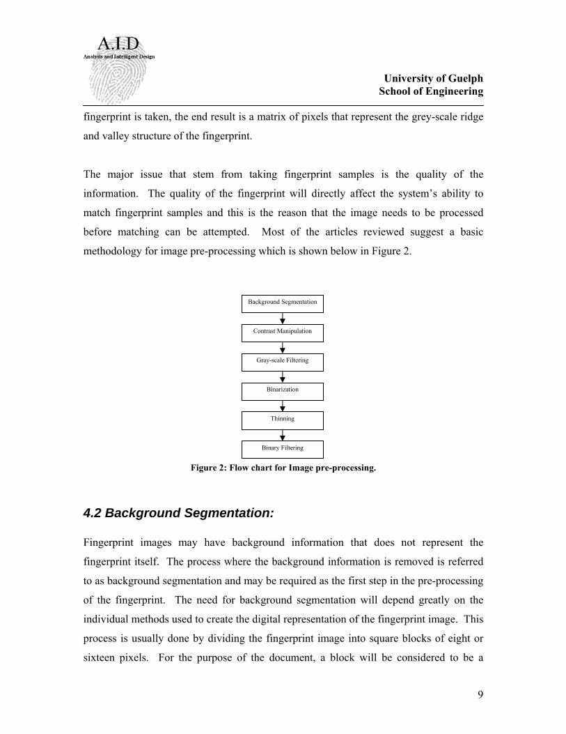
before matching can be attempted. Most of the articles reviewed suggest a basic
methodology for image pre-processing which is shown below in Figure 2.
Figure 2: Flow chart for Image pre-processing.
4.2 Background Segmentation: Fingerprint images may have background information that does not represent the
fingerprint itself. The process where the background information is removed is referred
to as background segmentation and may be required as the first step in the pre-processing
of the fingerprint. The need for background segmentation will depend greatly on the
individual methods used to create the digital representation of the fingerprint image. This
process is usually done by dividing the fingerprint image into square blocks of eight or
sixteen pixels. For the purpose of the document, a block will be considered to be a
Background Segmentation
Contrast Manipulation
Gray-scale Filtering
Binarization
Thinning
Binary Filtering
University of Guelph School of Engineering
10
square sample from the image matrix. The variance in the grey-levels of the pixels in a
block is then compared to the variance of the entire image. Any block that varies beyond
some threshold will then be considered information that is not valid for the fingerprint.
This is a fairly easy task but the problem lies in correctly choosing what threshold will be
used to properly separate the background from the fingerprint image. So far trial and
error has been used to determine this threshold value. Images that do not have a
background or extraneous information do not need to be segmented. The images that we
assume are supplied do not have ambiguous background information and therefore the
segmentation function is not implemented in our final filtration process.
4.3 Contrast Manipulation: The quality of fingerprints will almost never be of a consistent quality. In fact most will
be fairly poor. For this reason fingerprints need to be enhanced to improve the quality of
the results. To improve the quality of the fingerprint image some sort of filtering is
required. To aid in filtering the grey-scale levels of the fingerprint image are usually
manipulated to help enhance the effects of filtering. Two common methods of contrast
manipulation are normalization and histogram equalization. Normalization standardizes
the grey-level intensities of the pixels in the overall matrix of pixels that represent the
fingerprint. One method used to accomplish this uses the accepted mean and variance of
the pixel intensities in the image. The actual mean and variance of the fingerprint is also
calculated. This information is then used to shift the actual pixel intensities
proportionally to the manually specified mean and variance [7].
Another method suggested to enhance the contrast of an image is to use histogram
equalization [8]. This method was implemented in our project as per the first stage
presented in the article by Greenberg et al. The histogram equalization adjusts the grey-
level intensity of the pixels in the local neighbourhood to produce an image that has a
more balanced distribution of pixel intensities over the full range of values from 0 to 255.
University of Guelph School of Engineering
11
( )∑∑= =
×=w
i
w
jnew w
jiIjiI0 0
2
255,),(
w : is the size of the local neighbourhood The Greenberg et al article suggests that they performed the histogram equalization
based on a 13x13 local neighbourhood. We created a function that will perform the
histogram equalization on the input image and this function allows for the size of the
local neighbourhood to be specified in the function call.
After this stage the ridge and valley structure is not changed but the variation of the grey
levels or the pixels is reduced to aid with the future steps used to enhance the fingerprint.
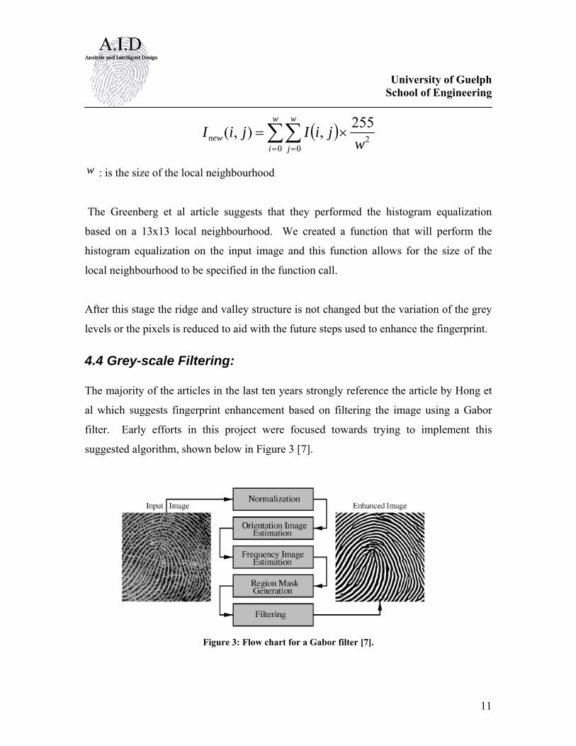
4.4 Grey-scale Filtering: The majority of the articles in the last ten years strongly reference the article by Hong et
al which suggests fingerprint enhancement based on filtering the image using a Gabor
filter. Early efforts in this project were focused towards trying to implement this
suggested algorithm, shown below in Figure 3 [7].
Figure 3: Flow chart for a Gabor filter [7].
University of Guelph School of Engineering
12
The main issue with this technique is that the Gabor filter requires an estimation of the
block orientation around each pixel and an estimation of each blocks frequency. This
information is then used create a complicated filter mask from the Gabor 2-D symmetric
filter equation. Once the mask is calculated it is then convolved with each pixel to
produce a filtered image for that block. This process is then repeated for every pixel and
the associated block around it. These three steps require complicated algorithms that are
computationally expensive and for this reason the Gabor filter will not be pursued further.
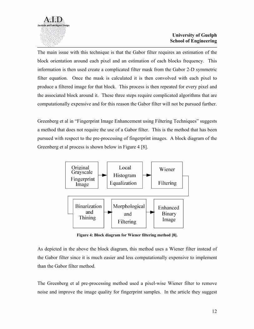
Greenberg et al in “Fingerprint Image Enhancement using Filtering Techniques” suggests
a method that does not require the use of a Gabor filter. This is the method that has been
pursued with respect to the pre-processing of fingerprint images. A block diagram of the
Greenberg et al process is shown below in Figure 4 [8].
Figure 4: Block diagram for Wiener filtering method [8].
As depicted in the above the block diagram, this method uses a Wiener filter instead of
the Gabor filter since it is much easier and less computationally expensive to implement
than the Gabor filter method.
The Greenberg et al pre-processing method used a pixel-wise Wiener filter to remove
noise and improve the image quality for fingerprint samples. In the article they suggest

University of Guelph School of Engineering
13
that the filtering is accomplished using a 3x3 filter mask generated using the given
equation.
( ) ( )( )μσνσμ −
++= 212
22
21 ,, nnInnw
μ : is the local mean
2σ : is the local variance 2ν : Estimation of the noise variance ( )21,nnI : is the grey level intensity of the pixel centering the 3x3 mask
The above equation requires an estimation of the noise variance but, does not suggest
how this should be calculated. In our implementation of the Wiener filter we calculated
the estimated noise variance using a method suggested by J. Immerkaer [10]. This
method used a 3x3 mask that was convolved about the pixel in question to calculate the
noise variance. This method was fast and fit well into the project. The mask is shown in
Figure 5
⎥⎥⎥
⎦
⎤
⎢⎢⎢
⎣
⎡
−−−
−
121242
121
361
Figure 5: Filter Mask for Noise Variance Estimation The function wiener() is used perform the Wiener filtering of the image.
4.5 Binarization: Binarization is easy to implement process that just compares each pixel to some threshold
and then changes it value to either pure white (0x00) or pure black (0xFF). The threshold
University of Guelph School of Engineering
14
used is usually either the global mean or a local block mean. This has been implemented
using a local block mean.
4.6 Thinning: The Greenberg et al article mentions the characteristics of their thinning algorithm but
does not actually state their algorithm. In our project we implemented two different
thinning algorithms.
The first thinning algorithm was implemented from Zhou [9]. This method thins an
image with two basic methods. First pixels in a 3x3 neighbourhood around the central
pixel are removed if their removal does not affect the connectivity of a ridge. The second
stage of the algorithm uses masks to ensure bifurcations are thinned properly.
The second thinning algorithm that was implemented was the MB2 thinning method.
This method uses a series of masks that are rotated around a central pixel at even
multiples of 90 degrees [10]. This method is a rotation invariant algorithm which means
the resulting image is not entirely reduced to a single pixel width. This rotational
invariant thinning might be useful however for a minutia matching process.
4.7 Binary Filtering: Once again Greenberg et al do not explicitly state the binary filtering algorithm that they
use but do state that this is fairly mechanical process of manually finding and removing
ridge structures that probably do not belong and by filling in gaps in ridges that do not
belong. We analyzed this problem and wrote a couple algorithms to solve this problem
removing spurs, ladder structures, and ambiguous lines. A function has not been created
which fills gaps but should be completed in future research to create an improved thinned
image.
University of Guelph School of Engineering
15
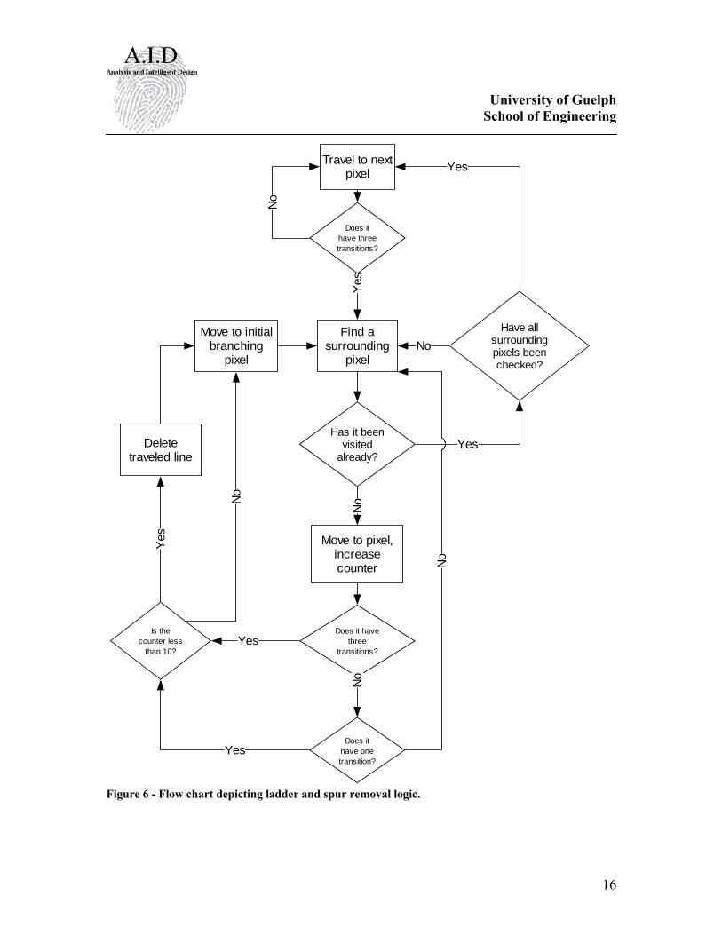
4.7.1 Ladder and Spur Removal Although Greenberg et al. mention the added benefit of implementing a function which
removes ladder structures and spurs, they do not elaborate on their method or suggest a
plan of action. Ladders are usually caused by pits in the ridge detail creating a false
region of lighter pixels which are then binarized incorrectly. These structures will lead to
ambiguous bifurcations being detected. Spurs are also caused by ridge or image
abnormalities but do not adjoin two valleys incorrectly. These will incorrectly generate
ridge endings. Even after subjecting an image to a series of filters these anomalies can
remain.
To solve this problem we created a function which first generates a mask which
represents the number of transitions about a single pixel when traveling in a clockwise
direction in relation to the image. The function then performed the following set of
operations.
University of Guelph School of Engineering
16
Travel to nextpixel
Does ithave threetransitions?
No
Find asurrounding
pixelYe
s
Has it beenvisited
already?
Have allsurroundingpixels beenchecked?
Yes
No
Yes
Move to pixel,increasecounter
No
Does it havethree
transitions?
Does ithave onetransition?
Move to initialbranching
pixel
Deletetraveled line
Is thecounter less
than 10?
Yes
Yes
No
Yes
No
No
Figure 6 - Flow chart depicting ladder and spur removal logic.

University of Guelph School of Engineering
17
This function adequately removed the aforementioned structures resulting in a much
cleaner image. By running this function the number of false minutiae points are
drastically reduced.
4.7.2 De-Line Function This function exhaustively inspects each line by following its path within the fingerprint.
If the line is less than 10 pixels long we assume that the line can be deleted. It
accomplishes this by systematically examining each pixel. When it comes to a pixel
which is an end point it continues along the path until another end point has been reached
using the same method outlined in the flow chart above. Any ambiguous lines remaining
in a final image contribute to the frequency of ridge endings when extracting minutiae.
By removing these lines the number of points which must be analyzed drastically
decreases.
4.8 Other Functions
We have created some other functions that are either used to display information about
the fingerprint image or were created during the early stages of the project but may be
useful in future work in this area. A brief description of their utility is listed below.
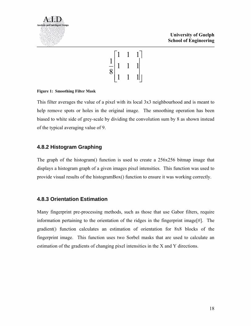
4.8.1 Image Smoothing The Greenberg et al pre-processing method started by performing a histogram
equalization of the fingerprint image. We started our pre-processing by first passing the
image through a smoothing filter.
University of Guelph School of Engineering
18
⎥⎥⎥
⎦
⎤
⎢⎢⎢
⎣
⎡
111111111
81
Figure 1: Smoothing Filter Mask This filter averages the value of a pixel with its local 3x3 neighbourhood and is meant to
help remove spots or holes in the original image. The smoothing operation has been
biased to white side of grey-scale by dividing the convolution sum by 8 as shown instead
of the typical averaging value of 9.
4.8.2 Histogram Graphing The graph of the histogram() function is used to create a 256x256 bitmap image that
displays a histogram graph of a given images pixel intensities. This function was used to
provide visual results of the histogramBox() function to ensure it was working correctly.
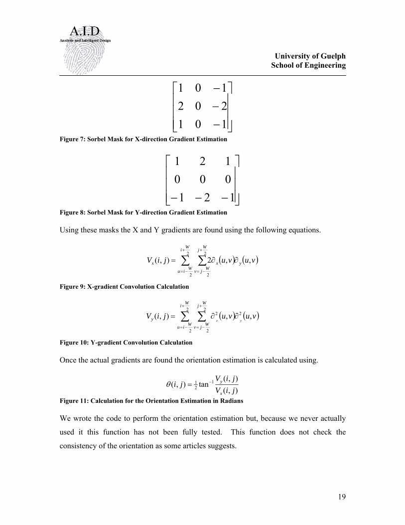
4.8.3 Orientation Estimation Many fingerprint pre-processing methods, such as those that use Gabor filters, require
information pertaining to the orientation of the ridges in the fingerprint image[#]. The
gradient() function calculates an estimation of orientation for 8x8 blocks of the
fingerprint image. This function uses two Sorbel masks that are used to calculate an
estimation of the gradients of changing pixel intensities in the X and Y directions.
University of Guelph School of Engineering
19
⎥⎥⎥
⎦
⎤
⎢⎢⎢
⎣
⎡
−−−
101202101
Figure 7: Sorbel Mask for X-direction Gradient Estimation
⎥⎥⎥
⎦
⎤
⎢⎢⎢
⎣
⎡
−−− 121000121
Figure 8: Sorbel Mask for Y-direction Gradient Estimation Using these masks the X and Y gradients are found using the following equations.
( ) ( )∑ ∑+
−=
+
−=
∂∂=2
2
2
2
,,2),(
Wi
Wiu
Wj
Wjv
yxx vuvujiV
Figure 9: X-gradient Convolution Calculation
( ) ( )∑ ∑+
−=
+
−=
∂∂=2
2
2
2
22 ,,),(
Wi
Wiu
Wj
Wjv
y vuvujiVyx
Figure 10: Y-gradient Convolution Calculation Once the actual gradients are found the orientation estimation is calculated using.
),(),(
tan),( 121
jiVjiV
jix
y−=θ
Figure 11: Calculation for the Orientation Estimation in Radians We wrote the code to perform the orientation estimation but, because we never actually
used it this function has not been fully tested. This function does not check the
consistency of the orientation as some articles suggests.
University of Guelph School of Engineering
20
4.8.4 Median Filter The function median() will perform a median filter for the given image. This filter
functionally replaces the given pixels intensity with the median pixel intensity of a local
5x5 block.
5. Results
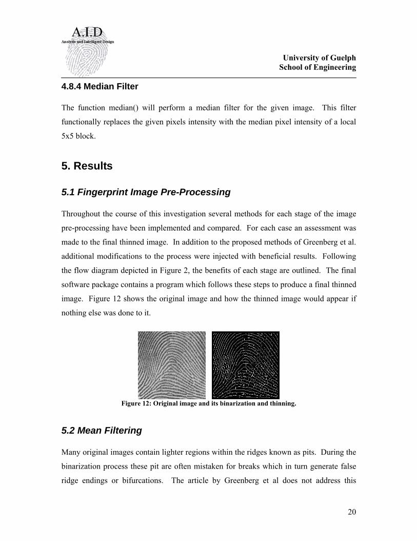
5.1 Fingerprint Image Pre-Processing Throughout the course of this investigation several methods for each stage of the image
pre-processing have been implemented and compared. For each case an assessment was
made to the final thinned image. In addition to the proposed methods of Greenberg et al.
additional modifications to the process were injected with beneficial results. Following
the flow diagram depicted in Figure 2, the benefits of each stage are outlined. The final
software package contains a program which follows these steps to produce a final thinned
image. Figure 12 shows the original image and how the thinned image would appear if
nothing else was done to it.
Figure 12: Original image and its binarization and thinning.
5.2 Mean Filtering Many original images contain lighter regions within the ridges known as pits. During the
binarization process these pit are often mistaken for breaks which in turn generate false
ridge endings or bifurcations. The article by Greenberg et al does not address this
University of Guelph School of Engineering
21
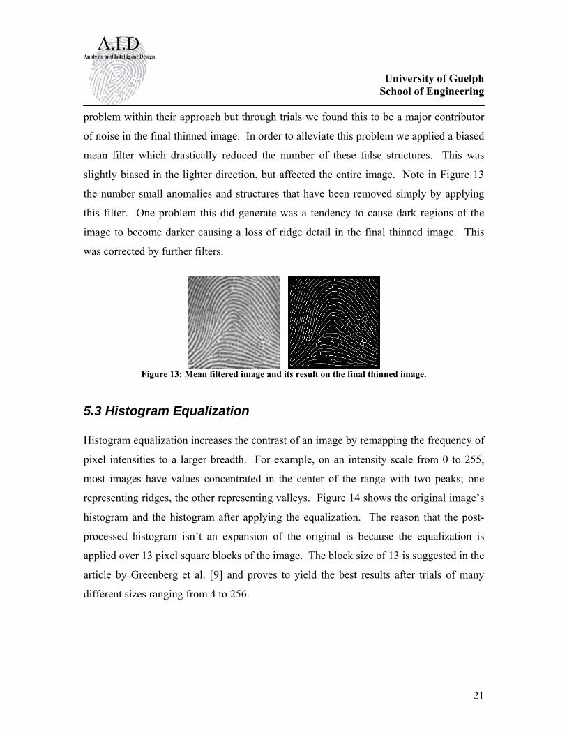
problem within their approach but through trials we found this to be a major contributor
of noise in the final thinned image. In order to alleviate this problem we applied a biased
mean filter which drastically reduced the number of these false structures. This was
slightly biased in the lighter direction, but affected the entire image. Note in Figure 13
the number small anomalies and structures that have been removed simply by applying
this filter. One problem this did generate was a tendency to cause dark regions of the
image to become darker causing a loss of ridge detail in the final thinned image. This
was corrected by further filters.
Figure 13: Mean filtered image and its result on the final thinned image.
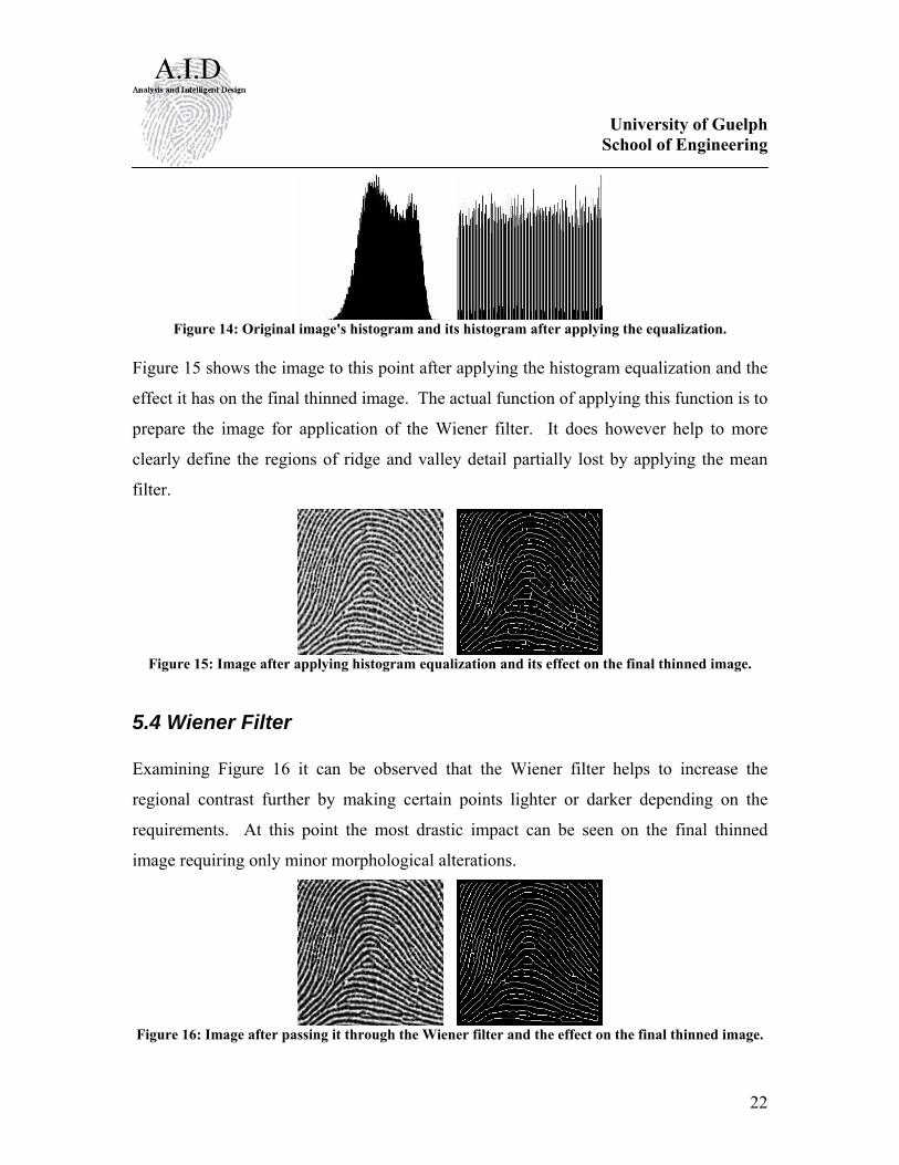
5.3 Histogram Equalization Histogram equalization increases the contrast of an image by remapping the frequency of
pixel intensities to a larger breadth. For example, on an intensity scale from 0 to 255,
most images have values concentrated in the center of the range with two peaks; one
representing ridges, the other representing valleys. Figure 14 shows the original image’s
histogram and the histogram after applying the equalization. The reason that the post-
processed histogram isn’t an expansion of the original is because the equalization is
applied over 13 pixel square blocks of the image. The block size of 13 is suggested in the
article by Greenberg et al. [9] and proves to yield the best results after trials of many
different sizes ranging from 4 to 256.
University of Guelph School of Engineering
22
Figure 14: Original image's histogram and its histogram after applying the equalization.
Figure 15 shows the image to this point after applying the histogram equalization and the
effect it has on the final thinned image. The actual function of applying this function is to
prepare the image for application of the Wiener filter. It does however help to more
clearly define the regions of ridge and valley detail partially lost by applying the mean
filter.
Figure 15: Image after applying histogram equalization and its effect on the final thinned image.
5.4 Wiener Filter Examining Figure 16 it can be observed that the Wiener filter helps to increase the
regional contrast further by making certain points lighter or darker depending on the
requirements. At this point the most drastic impact can be seen on the final thinned
image requiring only minor morphological alterations.
Figure 16: Image after passing it through the Wiener filter and the effect on the final thinned image.
University of Guelph School of Engineering
23
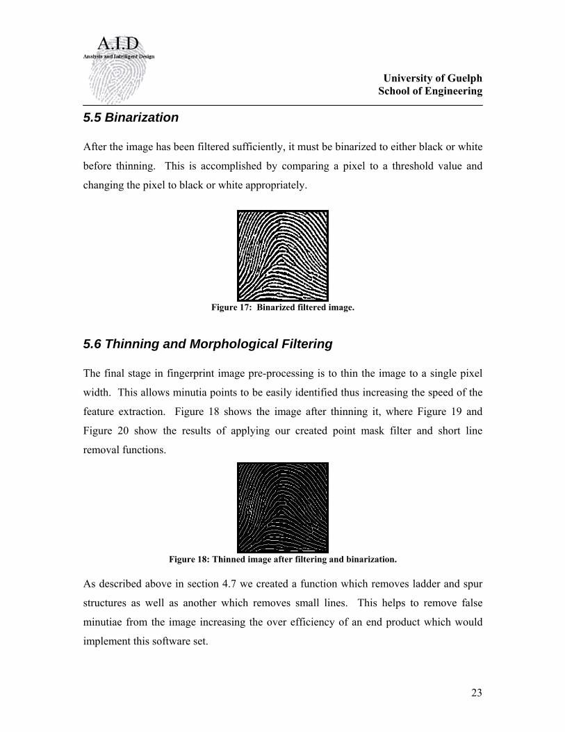
5.5 Binarization After the image has been filtered sufficiently, it must be binarized to either black or white
before thinning. This is accomplished by comparing a pixel to a threshold value and
changing the pixel to black or white appropriately.
Figure 17: Binarized filtered image.
5.6 Thinning and Morphological Filtering The final stage in fingerprint image pre-processing is to thin the image to a single pixel
width. This allows minutia points to be easily identified thus increasing the speed of the
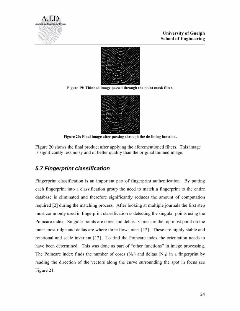
feature extraction. Figure 18 shows the image after thinning it, where Figure 19 and
Figure 20 show the results of applying our created point mask filter and short line
removal functions.
Figure 18: Thinned image after filtering and binarization.
As described above in section 4.7 we created a function which removes ladder and spur
structures as well as another which removes small lines. This helps to remove false
minutiae from the image increasing the over efficiency of an end product which would
implement this software set.
University of Guelph School of Engineering
24
Figure 19: Thinned image passed through the point mask filter.
Figure 20: Final image after passing through the de-lining function.
Figure 20 shows the final product after applying the aforementioned filters. This image is significantly less noisy and of better quality than the original thinned image.
5.7 Fingerprint classification Fingerprint classification is an important part of fingerprint authentication. By putting
each fingerprint into a classification group the need to match a fingerprint to the entire
database is eliminated and therefore significantly reduces the amount of computation
required [2] during the matching process. After looking at multiple journals the first step
most commonly used in fingerprint classification is detecting the singular points using the
Poincare index. Singular points are cores and deltas. Cores are the top most point on the
inner most ridge and deltas are where three flows meet [12]. These are highly stable and
rotational and scale invariant [12]. To find the Poincare index the orientation needs to
have been determined. This was done as part of “other functions” in image processing.
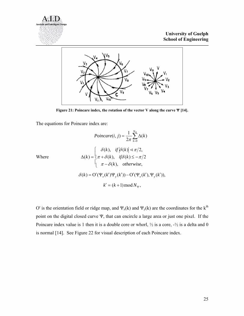
The Poincare index finds the number of cores (NC) and deltas (ND) in a fingerprint by
reading the direction of the vectors along the curve surrounding the spot in focus see
Figure 21.
University of Guelph School of Engineering
25
Figure 21: Poincare index, the rotation of the vector V along the curve Ψ [14].
The equations for Poincare index are:
∑Ψ
=
Δ=N
kkjiPoincare
0)(
21),(π
Where ⎪⎩
⎪⎨
⎧
−−≤+=Δ
,),(2)(),(
,2)(),()(
otherwisekkifk
kifkk
δππδδπ
πδδ <
)),(),(())()(()( kkkkk yxyx ′Ψ′ΨΟ′−′Ψ′ΨΟ′=δ
,mod)1( Ψ+=′ Nkk
O' is the orientation field or ridge map, and Ψx(k) and Ψy(k) are the coordinates for the kth
point on the digital closed curve Ψ, that can encircle a large area or just one pixel. If the
Poincare index value is 1 then it is a double core or whorl, ½ is a core, -½ is a delta and 0
is normal [14]. See Figure 22 for visual description of each Poincare index.

University of Guelph School of Engineering
26
Figure 22: The Poincare index for each type of singular point [13].
To classify using the Poincare index the orientation of the singular points to each other
can be used to distinguish between right loops and left loops. Classification of a
fingerprint can be determined using Poincare index based on the number of cores and
deltas and the orientation of the cores and deltas to each other.
Table 1: Classification based on singular points [12]. Pattern Class Core Delta Arch 0 0 Tented Arch 1 1 (middle) Left Loop 1 1 (right) Right Loop 1 1 (left) Whorl 2 2
After the Poincare indices have been found the way the rest of the classification method
proceeds is different for every journal. There is pseudoridge tracing [12], ridge structure
[handbook], neural network classifier [13], two-stage classifier [13], and nearest k-
neighbour [13]. For the most part the difficulty level of 5 different methods is the same.
Based on accuracy for a 4 – class classification the pseudoridge method would be the best
approach. The accuracy of classification increases when the number of classification
groups is decreased from 5 groups to 4 groups. The problem that rises from having 5
groups is the similarities between the arch and tented arch [12]. This then leads to the
University of Guelph School of Engineering
27
tented arch being classified as an arch [12]. When these two groups are combined into
one the accuracy increases from 84% to 95.3% [12] as seen in Table 2.
Table 2: Comparison between different classification methods. Classification 5 – Class Accuracy % 4 – Class Accuracy % Pseudoridge tracing 84 95.3 Neural Network 90 94.8 Ridge Structure 87.5 92.3 Two-Stage Classifier 86.4 92.1 Nearest K-neighbour 85.4 91.5
6. Discussion Image Pre-Processing:
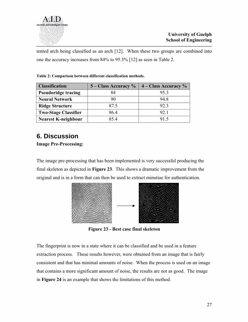
The image pre-processing that has been implemented is very successful producing the
final skeleton as depicted in Figure 23. This shows a dramatic improvement from the
original and is in a form that can then be used to extract minutiae for authentication.
Figure 23 - Best case final skeleton
The fingerprint is now in a state where it can be classified and be used in a feature
extraction process. These results however, were obtained from an image that is fairly
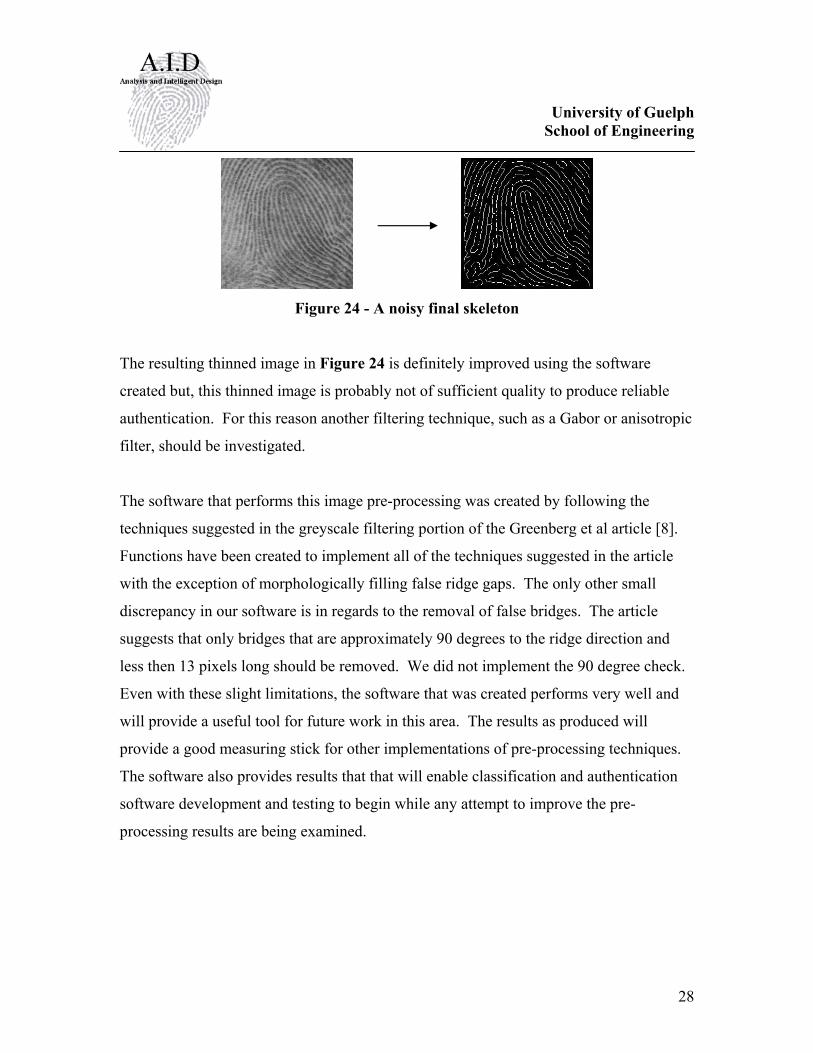
consistent and that has minimal amounts of noise. When the process is used on an image
that contains a more significant amount of noise, the results are not as good. The image
in Figure 24 is an example that shows the limitations of this method.
University of Guelph School of Engineering
28
Figure 24 - A noisy final skeleton
The resulting thinned image in Figure 24 is definitely improved using the software
created but, this thinned image is probably not of sufficient quality to produce reliable
authentication. For this reason another filtering technique, such as a Gabor or anisotropic
filter, should be investigated.
The software that performs this image pre-processing was created by following the
techniques suggested in the greyscale filtering portion of the Greenberg et al article [8].
Functions have been created to implement all of the techniques suggested in the article
with the exception of morphologically filling false ridge gaps. The only other small
discrepancy in our software is in regards to the removal of false bridges. The article
suggests that only bridges that are approximately 90 degrees to the ridge direction and
less then 13 pixels long should be removed. We did not implement the 90 degree check.
Even with these slight limitations, the software that was created performs very well and
will provide a useful tool for future work in this area. The results as produced will
provide a good measuring stick for other implementations of pre-processing techniques.
The software also provides results that that will enable classification and authentication
software development and testing to begin while any attempt to improve the pre-
processing results are being examined.
University of Guelph School of Engineering
29
Fingerprint Classification:
When is comes to classification of fingerprints there many different approaches to take.
The approach that is recommended for the next step in this project would be to get a
working Poincare index and pseudo ridge tracing program that classifies a fingerprint.
The groups recommended for classification are Arch, Right Loop, Left Loop and Whorl,
and to rejects fingerprints that do not fall into any of these 4 categories.
7. Conclusions While investigating the process of fingerprint-based user authentication it was found that
it should be broken into three main groups of image pre-processing, classification, and
feature extraction and authentication. Within these three topics there are many
subsections which must be addressed.
A software package was created that implement’s pre-processing techniques as suggested
in the Greenberg et al. article [8] to make a one-pixel thick skeleton of the fingerprint to
prepare it for classification and feature extraction.
A few other functions were looked into and have been created but were not implemented
into this pre-processing method, but may be implemented in further research.
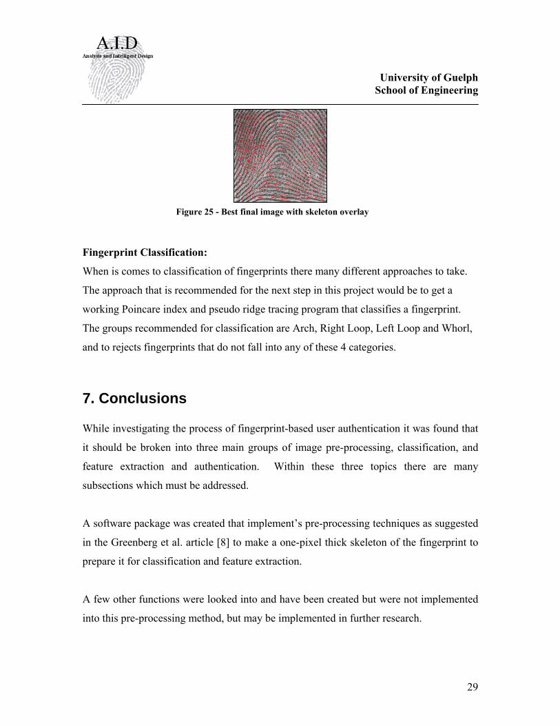
Figure 25 - Best final image with skeleton overlay
University of Guelph School of Engineering
30
The recommended method of classification is calculating the Poincare index to find the
singular points in combination with ridge line tracing. The recommended groupings
include Arch, Right Loop, Left Loop, and Whorl.
8. Recommendations The quality of the results from the pre-processing stage of the fingerprint authentication
will greatly affect a systems ability to successfully classify and reliably match biometric
features. Within the pre-processing stage the most important process is by far the
filtering of less then perfect images. In this project we used a method of image pre-
processing based on the Greenberg et al article [8]. This article used a Wiener filter. In
the equation used to create the Wiener filter convolution mask an estimate of the noise
variance is required. We used a method suggested by Jain to perform this calculation.
This decision should be reviewed or compared to another method used to estimate the
noise variance. After Wiener filtering and thinning the Greenberg et al article suggests
the thinned image should be morphologically filtered to remove spurs, false bridges and
to fill false ridge gaps. Near the end to this project we implemented some basic methods
to remove spurs and false bridges. These methods should be reviewed, most likely by
implementing an alternate method from another article. A method to fill false ridge gaps
needs to implement as there is no function to perform this in the software package. Two
other methods of filtering commonly suggested in fingerprint articles use Gabor or
Isotropic filtering techniques [8]. Although these methods may be mathematically
complex and computationally intensive they should be implemented to asses their merit.
During the scope of the project other functions mentioned in the method such as the
function to find the orientation of the ridge structure, normalize an image and perform
background segmentation were written but not fully tested. These functions should
provide assistance in future research but require testing. The normalize function requires
an assigned value for the mean and variance that the image is normalized to. A
University of Guelph School of Engineering
31
reasonable method to assign these values needs to be determined [9]. The background
segmentation function has two variables that affect its function and need to be considered
in any future use. These variables are the block size of each segment and the threshold
value that determines if a block is segmented or not. The function that calculates the
orientation of the ridge structure within the fingerprint image was written but, needs to be
tested and potentially needs to have a consistency check function added to ensure noise
does not cause invalid results. The software package should be streamlined by
implementing a function that performs convolution. Right now each function that now
each function that performs a convolution operation has this operation embedded within
it.
The next step in this project is to classify the fingerprints that have been filtered through
the image processing functions. The gradient function which was created when
beginning some of the advanced filtering techniques can be used to map the fingerprint’s
local orientation. Most classification schemes use this orientation value in tandem with
other approaches to classify the fingerprint. A classification method has been suggested
which uses the Poincare index along with pseudoridge tracing to classify the fingerprint
into either the Arch, Left loop, Right loop, or Whorl class. After that, minutia points are
located and mapped, then compared to a database of fingerprints.
In the long term this project should look at taking the whole authentication process and
converting it to a form that can be run on an FPGA. By designing the system to process
redundant calculations in parallel, such as matrix convolution, the entire system will be
much faster and allow it to be ported to an embedded system.
University of Guelph School of Engineering
32
9. References
[1] A. Jain, “Fingerprint matching”, http://www.pims.math.ca/industrial/2002/mitacs-agm/jain/, January 2007.
[2] A. Jain and S. Pankanti, “Fingerprint Classification and Matching”, http://www.research.ibm.com/ecvg/pubs/sharat-handbook.pdf, January 2007.
[3] R. Bolle, J Connell, S. Pankanti, N. Ratha and A. Senior, “Guide to Biometrics” New York: Springer, 2004.
[4] “Fingerprint Identification”, http://webfea-lb.fea.aub.edu.lb/dsaf/labs/projectv1.1.pdf, January 2007.
[5] M. Aladjem, I. Dimitrov, S. Greenberg and D. Kogan, “Fingerprint Image Enhancement using Filtering Techniques,” Pattern Recognition, 2000. Proceedings. 15th International Conference, Vol. 3, pp. 322-325, 2000.
[6] X. Jiang, and W. Yua, “Fingerprint Minutiae Matching Based on the Local And Global Structures”, 15th International Conference on Pattern Recognition (ICPR'00). Vol.2. 2000. pp. 1038-1401. [7] L. Hong, Y Wan, and A. Jain, “Fingerprint Image Enhancement: Algorithm and Performance Evaluation,” IEEE Trans. Pattern Analysis and Machine Intelligence, vol. 20, no.8,pp.777-789, 1998 [8] S. Greenberg, M. Aladjem, D. Kogan, and I. Dimitrov, “Fingerprint image enhancement using filtering techniques”, Pattern Recognition, Proceedings. 15th International Conference on, vol. 3, pp. 322-325, 2000. [9] R. Zhou, C. Quek, and G.S. Ng, A novel single-pass thinning algorithm and an effective set of performance criteria Pattern Recognition Letters, 16(12), 1267-1275, 1995 [10] T.M. Bernard; A. Manzanera. “Improved Low Complexity Fully Parallel Thinning Algorithm”. Image Analysis and Processing, 1999, Proceedings, International Conference on 27-29 September 1999, 215-220. [11] J. Immerkaer. “Fast Noise Variance Estimation”. Computer Vision and Image Understanding, vol. 64, no 2, September, pp 300-302, 1992. [12] Q. Zhang, K. Huang, and H. Yan, “Fingerprint Classification Based on Extraction and Analysis of Singularities and Pseudoridges” 2006

University of Guelph School of Engineering
33
[13] A. Jain and S. Prabhakar, “A Multichannel Approach to Fingerprint Classification”, IEEE Transactions on Pattern Analysis and Machine Intelligence, Vol. 21, No. 4, April 1999. [14] Kawagoe, M; Tojo, A. “Fingerprint Pattern Recognition.” Pattern Recognition, vol 17. No 3, pp 295-303, 1984.
University of Guelph School of Engineering
34
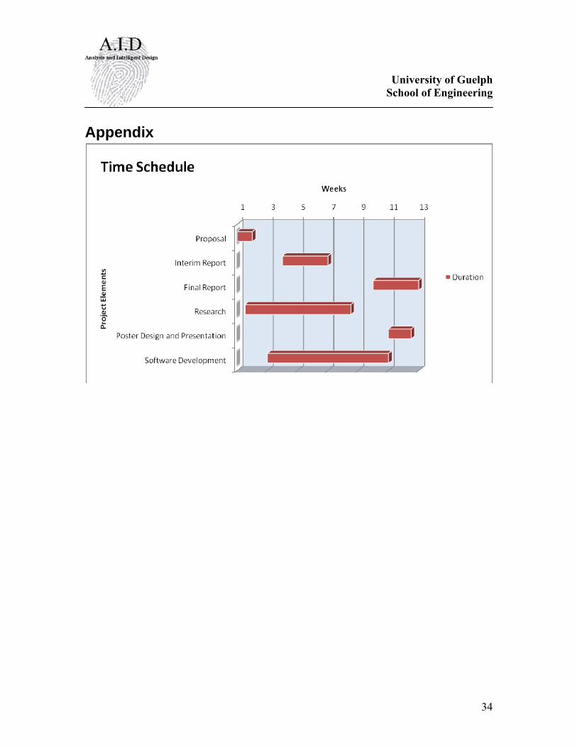
Appendix