final report - duxbury systems
TRANSCRIPT

'
•
•

FINAL REPORT
to
JOHN A. HARTFORD FOUNDATION, INC.
on the Grant entitled
"Development of a High-speed Brailler System for more Rapid and Extensive Production of
Informational Material for the Blind."
during the period
1 July 1967 through 30 June 1970
George F. Dalrymple
from
Sensory Aids Evaluation and Development Center
Massachusetts Institute of Technology
292 Main Street
Cambridge, Massachusetts 02142
29 September 1970

TABLE OF CONTENTS
INTRODUCTION
BRAILLEMBOSS DEVELOPMENT
Page 1
2
BRAILLB1BOSS APPLICATIONS 7
PERSONNEL 11
REFERENCES 13
APPENDIX I EVALUATION OF THE HIT AUTOXATIC BRAILLER 15
APPENDIX II BRAILLEMBOSS DESCRIPTIONS 17
APPENDIX III BRAILLEMBOSS SPECIFICATIONS 29
APPENDIX IV TECH~ICAL DESCRIPTIONS SHEETS
TDS No . 2 - BRAILLEMBOSS , A Braille Page Printer 37
TDS ~o . 3 - DOTSYS - A Braille Translation Program 39
TDS No . 5 - BRAILLEHBOSS APPLICATIONS 41
TDS No . 7- A Pamphlet , "The American Revolution". 43
TDS No . 8 - ONE- CELL Braille Translators 45 BRAILLDlBOSS Inter face Units
TDS No . lO - Conversion Table, Inches to Milli- 47 meters , A Braille Computer Generated Mathematical Table
TDS No . l2 - BRAILLE NEWS DEMONSTRATION 49
0745498


INTRODUCTION
A blind mathematician sits at a teletype and communicates with a
computer. At his elbow is an MIT BRAILLEMBOSS. For each key stroke on
the teletype the BRAILLEMBOSS prints the character in braille. The com
puter answers him and again the message is printed in braille. With the
BRAILLEMBOSS he becomes a fully functioning professional with equal access
to the time-sharing computer as his sighted colleagues.
A blind upper school student in a residential school, far away from
a computer is learning to be a computer programmer . A teletype and BRAILL
~lBOSS are her connections with the computer. With the braille printout
she also is equal with sighted students in her access to the computer.
A blind graduate student must read a memo that his professor has
stored in a computer for all his students. The student sits at a teletype,
dials the computer, turns on a BRAILLEMBOSS, types a few simple commands
and the BRAILLEMBOSS beside him produces a braille copy literally under his
fingertips . When the memo is completely brailled, he releases the computer
with a few typed commands, turns off the BRAILLEMBOSS, tears off his memo
and takes it home to study.
A blind radio announcer must prepare the next news broadcast. He goes
to a BRAILLEMBOSS printing the wire services pre-edited newscasts . He tears
off the copy, quickly scans the content, and with a pair of scissors selects
the sequence of stories. He reads over the newscast and is then ready to be
on-the-air with the news--without sighted help.
A clerk in a public school office is handed a report by a teacher to be
duplicated for her students, one of whom is blind. The clerk duplicates the
copy in the usual fashion, then sits down at a teletype, a computer is dialed,
a few brief commands are typed, then the report is typed into the computer.
The computer translates the material into Grade II braille and sends the trans
lated material to the BRAILLEMBOSS . The braille material is immediately avail
able, almost as fast as the inkprint, ready to be given to the students. The

2
braille was produced using approximately the same effort and skills as
the inkprint copies .
A volunteer braille agency is asked for ten copies of a short braille
work. An expert braillist, using a special Perkins braille writer equipped
with a paper tape punch, brailles a copy. The punched paper tape is then
used as input to a tape reader attached to the BRAILLEMBOSS and the document
is produced at the rate of approximately one page a minute. In the absence
of a trained braillist, the punched paper tape could have been prepared via
computer translation using a straight typist to type the material into the
computer as was done in the previous example.
These examples demonstrate what can be accomplished with the BRAILL
EMBOSS. The first three are true examples of what has been already accom
plished with the BRAILLEMBOSSES made under the Hartford Grant while the last
three examples have been demonstrated in principle.
BRAILLEMBOSS DEVELOPHENT
The goal of the project was the development of a manufacturing model
of the MIT BRAILLEMBOSS including the production of twenty test models for
placement and evaluation in Boston area schools. Two basic models of the
BRAILL~1BOSS have been produced in quantities as shown in Table I. One unit
has been installed at a school, Perkins School for the Blind; another, in
the office of a blind mathematician at the Transportation System Center of
the Department of Transportation (formerly NASA's Electronic Research Center);
and two are installed with computer terminals at the SAEDC.
The BRAILL~1BOSS is one of the output devices needed for a
computerized Braille Information Processing System (BIPS) described
previously1
'2
It is the product of the effort of many students, faculty
and staff of the Mechanical Department and the SAEDC. The earliest studies 3
lead to the original operating design4
The second design5 ' 6 ' 7 was incorporate 8
into a console and demonstrated in a residential school, Perkins School for . 9,10
the Bhnd .

3
TABLE I
BRAILLEMBOSS TYPE SUMMARY
Braillemboss Type
Machine II 6
First Prototype
Model 3
Second Prototype
Model 4
Quantity
*
1
14
1
5
Purpose
To verify certain design changes before constructing prototype unit .
To verify the design of the Model 3 BRAILLEMBOSS
A Braille Page Printer with immediate but not instantaneous access to the braille page
To verify the design changes for the Model 4 BRAILL&~BOSS
A braille page printer for a time-sharing computer terminal where instantaneous access to the braille is required
*The Machine II 6 was the last of the previous group of braillers and was available for experimentation. It is still operational with paper tape input .
4
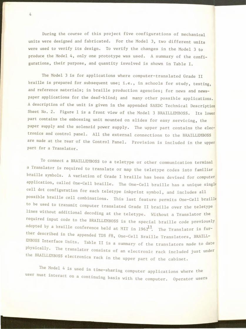
During t he course of this project five configurations of mechanical
units were designed and fabricated . For the Model 3, two different units
wer e used to verify its design . To verify the changes in the Model 3 to
produce the Model 4, only one prototype was used . A summary of the confi
gur ations, their purpose, and quantity involved is shown in Table I.
The Model 3 is for applications where computer-translated Grade II
braille is prepared for subsequent use; i.e., in schools for study, testing ,
and reference materials; in braille production agencies; for news and news
paper applications for the deaf - blind; and many other possible applications .
A description of the unit is given in the appended SAEDC Technical Description
Sheet No . 2 . Figure 1 is a front view of the Model 3 BRAILLEMBOSS. Its lower
part contains the embossing unit mounted on slides for easy servicing, the
paper supply and the solenoid power supply. The upper part contains the elec
tronics and control panel. All the external connections to the BRAILLEMBOSS
are made at the rear of the Control Panel. Provision is included in the upper
part for a Translator .
To connect a BRAILLB1BOSS to a teletype or other communication terminal
a Translator is required to translate or map the teletype codes into familiar
braille symbols . A variation of Grade I braille has been devised for computer
application, called One-Cell braille. The One-Cell braille has a unique single
cell dot configuration for each teletype inkprint symbol, and includes all
possible braille cell combinations. This last feature permits One-Cell braille
to be used to transmit computer translated Grade II braille over the teletype
lines without additional decoding at the teletype . Without a Translator the
required input code to the BRAILLE.."'iBOSS is the special braille code previously
adopted by a braille conference held at MIT in 196.111. The Translator is fur
ther described in the appended TDS #8, One-Cell Braille Translators, BRAILL
DlBOSS Interface Units. Table II is a summary of the translators made to date
physically. The translator consists of an electronic rack included just under
the BRAILLB-1BOSS electronics rack in the upper part of the cabinet.
The Model 4 is used 1·n t · h h 1me-s aring computer applications where t e
user must interact on a continuing basis with the computer. Operator users

5
Figure 1
Model 3 BRAILLEMBOSS
6
Type No. Made
ASCII/DOTSY S 4
ASCII 2
Bardot 1
Table Jl
Translators
Function
' 1 . To provide electrical interface between Hodel 35 Teletypes with a stunt box or LRS 800 Receiving Selector and BRAILLEMBOSS .
2a . To translate teletype codes into the appropriate braille codes, or
2b. To translate DOTSYS transmission codes into braille codes .
la. To provide electrical interface between Model 35 Teletypes with a stunt box or LRS 800 Receiving Selector and BRAILLEMBOSS, or
lb. To provide electrical interface between Models 33, 35 , or 37 Teletypes selector magnet driver and BRAILLEMBOSS.
2. To translate teletype codes into the appropriate braille codes .
1. To provide electrical interface between 5 level tape reader (Model 9 or 15 Teletype) and BRAILLEMBOSS .
2. To translate teletype codes into the appropriate braille codes.

wss.
iOSS,
7
include computer programmers, engineers using the computer to solve en
gineering problems, financial analysts using computer-stored data banks
and other similar operator users. Figure 2 is a view of the t-1odel 4 . The
arrangement of the several units is similar to the ~ode! 3 except for the
location of the embossing unit.
An important consideration of the Hodel 4 BRAILLEHBOSS is the correct
height and placement of the embossing unit for the user ' s convenience, com
fort , and utility. A simple cabinet was designed from slotted angle to permit
quick and easy changes and adjustments to optimize the location of ti1e em
bossing unit and the control panel . Figure 3 is a view of the Second Prototype
as it has been connected to a teletype for regular use in the SAEDC ongoing
braille programs .
BRAILLf:0:·1BOSS APPLICATIONS
* fhe first prototype was extensively operated by an Exerciser to deter-
mine and demonstrate its reliability . After it had produced over 10 million
characters with little or no maintenance, it was connected to a computer via
teletype and was available on-line with an HIT time sharing comp u ter (CTSS) between
June 1969 and May 1970. It was used both by an economics graduate student in
his part-time employment as a systems analyst in the MIT Department of Economics ,
and for demonstrations and tests by the Center ' s personnel . It is temporarily
disconnected while other units are being tested .
The first Model 3 machine was demonstrated via tape reader input using
Teletype (ASCII) coded punched paper tape at the " Blind in Computer Programming ,
an International Conference'', held in Cleveland in October 1969 . The machine
operated correctly without adjustments at ti1e meeting after being transported
1100 miles by station wagon . After the conference the macl1ine was taken to
the office of Dr . John ~orrison, then of NASA, now of Department of Transpor
tation (DOT), and installed . He has used it extensively witi1 a Digital Equip
ment Corporation PDP-10 computer studying insertion trajectories and orbits of
* The Exerciser is an input device that creates repetitious patterns as inputs to the BRAILLC:·1BOSS to tes t and exercise the unit without use of teletypes, punched paper tape readers, or computers.
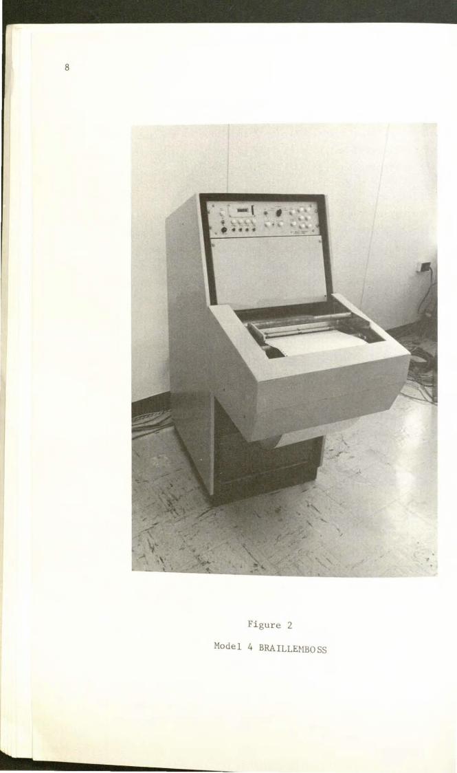
Figure 2
Model 4 BRAILLEHBO SS
9
Figure 3
Second Prototype with Teletype and Tape Reader

10
satellites. His report "Evaluation of MIT Automatic Brailler" written on
line using a computer editor routine is appended . The report was transmitted
to the SAEDC via teletype from the computer at DOT . This machine has em
bossed over 4 million characters with no maintenance except during the first
few weeks when two minor problems were corrected .
The second Model 3 machine was used to produce a conversion table of
inches to millimeters for the Hass . Commission for the Blind . A description
of this project is contained in Technical Description Sheet #10 . The unit
was installed at the Perkins School for the Blind in Watertown , Mass. during
February 1970. The BRAILLEMBOSS is connected in parallel to the page printer
of a teletype used in a computer programming course for the Perkins upper school
students. It has produced over 200 , 000 characters of braille at this writing.
They use the commercially available General Electric time-sharing service .
Another Model 3 machine has been used experimentally to produce in
braille a portion of the news stories carried by the UPI news wire . This de
monstration is described in TDS # 12 , Braille News Demonstration .
The Second Prototype was placed on-line during February 1970 and has
been used extensively for demonstrations, braille production and computer ter
minal operations since that time.
The first Model 4 machine was connected to the SAEDC second computer
terminal during May 1970 replacing the First Prototype . It is presently await
ing shipment to Dr . Edward Glaser , Director of the Case Western Reserve Universi~
Computation Center .
The remaining machines are complete mechanically . Five BRAILLEMBOSS
machines are complete and awaiting disposition . Each unit still must have the
translator required for its particular application. Two additional machines
need only plug-in electronic circuit cards. l'h e additional eight machines
still require both cabinets and some electronic COillponents .
11
PERSONNEL
The principal investigators were Dwight D. M. Bauman, formerly
Associate Professor of Mechanical Engineering; the late John K. Dupress,
Research Associate and Director SAEDC; Robert W. Mann, Professor of Mecha
nical Engineering; and Vito A.Proscia, Research Associate and Director of
SAEDC.
The Project Engineer was George F. Dalrymple who was also the
Electronic Engineer. The Mechanical Engineers were Murray Burnstine and
Ranulf W. Gras . Mr . Burnstine is a consulting engineer and had worked
previously on the embosser . Mr. Gras is a Staff Member of the Draper Labo
ratories (formerly Instrumentation Laboratory). Through Mr . Gras, the facilities
of Draper Laboratories, including metallurgy, inspection , instrument machine
shops and drafting were available to the project .
The Mechanical Technician was Norman J . Berube, the design draftsman
was Paul A. Maccarrone of Draper Laboratories , and the Electronics Technician
was Alexander Glimcher . Robert W. Reid , Mechanical Engineer , and Ernest P .
Johnson , Administrative Assistant, both of Draper Labor atories have contributed
to the project.

13
REFERENCES
1. Hann, R. W., "Enhancing the Availability of Braille", Proceedings of the International Congress on Technology and Blindness, New York, June 1962 .
2 . Dupress, J .K . , Baumann, D.~LB., Mann, R. W. , "Toward Making Braille As Accessible as Print", Engineering Projects Laboratory, MIT Report No. DSR 70249-1, June 1968.
3. Lichtman, S.A., The Design of a High-Speed Slave Brailler for a Braille Converter Device. Thesis (S.B.) Dept. of ~ech . Engr. ~ass.
Inst. of Tech. , May 1961.
4. Kennedy, D.W., A High Speed Braille Embossing System - 3 Volumes . Thesis (S .M. ) , Dept. of Mech . Engr., Mass . Inst . of Tech . May 1963 .
5 . Final Report of the Center for Sensory Aids Evaluation and Devel opment , M. I.T., October 1965.
6 . Final Report of the Center for Sensory Aids Evaluation and Development , M.I. T., April 1967 .
7. Proceedings - Braille Research Conference- Center for Sensory Aids Eval uation and Development , M. I .T., 1965 .
8. Armstrong , A.E., A Braille Telecommunication Terminal, Thesis (S . ~l . )
Dept. of Mech. Engr ., Mass . Inst. of Tech ., June 1965.
9 . Gre i ner, W.E ., Development of a Braille System for a Classroom Use . Thesis (S.M . ), Dept . of Mech . Engr ., Mass. Inst. of Tech ., March 1968 .
10. The Lantern , Vol. XXXVII , No . 3 , March 1968. "Perkins Exper i ment with Computer Produced Braille". Benjamin F . Smith, Assistant Director, and Editorial "Perkins Enters the Computer Age", Edward J . Waterhouse, Director.
11 . Conference on Automatic Data Processing and the Various Braille Codes , MIT, Cambridge , Mass . March 17 & 18, 1961 .


15
'\ 1 .I ' ' ,I t. h ll ' ~ l t ' 11 ' [ I [ ll I 1.. Ill . ... ,t. .... l <>g\
\I ' \ () g ) Ill>\ II Ill 1110' \1 ol I II \ I , ' ' I ( II Ill !J r I d _t: t , \ J ,, ' ' ,, c h 11 ' ( I I ' (J.!J..,.!
APPENDIX I
Evaluation of the ~t . I . T . Automatic Brailler
15 January 1970
The ~.I.T . Brailler has been located in my office in N.A . S . A. ' S Electronic Researcl1 Center in Cambridge , ~ass . for three months . The Brailler is connected to a teletypewriter which is , in turn, connected by a telephone line, to a Digital Equipment Corp . PDP-10 , a digital computer. I share this office with one other person .
I am blind ; my office mate is not . Both of us are PH . D., Aerospace engineers , emplo)ed by :\.A . S.A . to pursue research in the application of orbital mechanics to the determination of the motion of earth satellite . The teletypewriter has been used exclusively by us .
I have been involved in this type of work for ten years . By the n.1ture of the work, it has been essential to program tl1e results of my research on a computer for purposes of verification of the accuracy of Ll1e calculations , evaluation of the methods employed and investigation of possible applications . As is not unusual, I have called in programmers to carry out the actual programming and running of the results on a computer . I have had to rely on others to at least scan the numerical output in order to keep abreast of progress . The whole procedure has been quite unsatisfactory. The effort, time , cost, red tape, and the inefficiency of the procedures have led, in practice, to luying aside possible fruitful avenues for investigation .
With the advent of time-sharing capability , the situation has been completely altered. A scientist can now have direct access to the computer and almost zero turn-around time . However , for a blind scientist the time-sharing capability of computers is absolutely useless without a braille output device to reproduce the teletype output . It was my good fortune that, when the time-sharing facility became available to me , almost simultaneously, the M. I . T . Brailler was put at my disposal for evaluation purposes .
From a purely personal point of view , I cannot emphasize enough the almost unanticipated boost in morale the Brailler has afforded me . For the first time , I can access the computer directly and, for the first time, I can read the results of my labor . It is no exaggeration for me to say that, for the past three months , I have spent just about every waking moment either sitting at the Brailler and teletypewriter or preparing my next numerical experiment . Needless to say, I have not nearly exhausted the backlog, built up during the past ten years , of possible uses for the computer .
From the point of view of a productive worker, my contribution to the in- house effort has kept pace with my colleagues, which would not have been the case had I not had the Brailler at my disposal . I consider it an indispensable instrument for my work. Should I be deprived of its use, my value to my employer would suffer commensurately .
In my opinion, every possible effort should be made to ensure the development and further refinement of the M.I . T . Brailler and its availability to all blind persons who can demonstrate a legitimate use for it . The potential uses for the Brailler are by no means limited to my particular applications. The least that can be said is that whatever is available to a sighted person through a teletypewriter is available to a blind person through the addition of a Brailler. This capability alone is sufficient
to justify the development of the Brailler.
The M.I.T . Brailler does have some shortcomings, but they do not nearly cancel its advantages. One difficulty with the present design, and one which will take some ingenuity to eliminate, is the dropping of a character at the end of a line. This defect has been more of an annoyance to me, rather than a hindrance, since properly formatting the output circumvents line- overlap. Noise is another annoyance which can probably only be ameliorated under the present design. Some aspects of the Brailler which can be improved are : size of the machine, manner of presentation of the brailled material as it issues from the machine, and reliability.
John :-torrison
. Dr. Morrison wrote this report directly into the PDP-10 computer us:ng a teletype and BRAILLEMBOSS. A text editor program TECO (Text Ed1tor and COrrect' ) ' 10n was used to correct, insert delete and modify report as necessary Dr M · ' ' f t th · · orr1son then used an auxiliary program to orma d." report for the line length of the BRAILLEMBOSS. Following Dr. Morrison '
5
1~ec~10ns a teletype at the SAEDC was attached via telephone to the computer ~;omttheereport re~uested. The report was printed on the teletype directlY
computers memo Th' without furth d. . ry · 1S copy was retyped from the teletype copy er e 1t1ng.
George F. Ualrymple

The Model 3 BRAILLEl-IBOSS
Appendix II
BRAILLE·IBOSS DESCRIPTIONS
17
The !·1odel 3 BRAILLE.'1BOSS is a braille page printer designed to
produce braille for later reading. It is completely contained within a
single cabinet, and requires only input signals and AC power to operate.
The input signals can be derived from paper tape readers, teletype (or
other communication terminals), a computer keyboard, or many other similar
devices .
The basic components of the BRAILLEMBOSS are the embossing unit ,
electronics including the control panel, solenoid power supply and paper
supply . Provision is included in the cabinet for mounting the tape reader
power supply when the tape reader is used as input. The Model 3 embossing
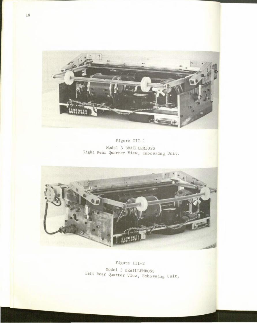
unit is shown in figures III-1 through III-5. The operation of the BRAILL
EMBOSS is discussed in Technical Description Sheet t/2, " BRAILLEMBOSS , A
Braille Page Printer" .
Many design changes were required for increased reliability , improved
accuracy, and reduced noise . These changes were sufficiently extensive to
require verification before incorporating them into the final design. As
many changes as was possible were installed on Machine No. 6 , the last machine
of the previous group made . These changes were tested and the machine oper -
ated extensively . One use of the Machine No . 6 during this period is described
in TDS 117 "A Pamphlet, 'The American Revolution ' , A Short Run Braille Production" .
Thesechanges are described fully in the section, Machine No.~
18
Figure III- 1
Model 3 BRAILLEMBOSS Right Rear Quarter View, Embossing Unit .
Figure III-2
Model 3 BRAILLEMBOSS Left Rear Quarter View, Emb oss ing Unit .

Figure Ill-3
Model 3 BRAILLEHBOSS Top View, Embossing Unit .
19

20
Figure III-4
Model 3 BRAILLEMEOSS Front View, Embossin.g Unit .
Figure Ill-S
Model 3 BRAILLEMBOSS Bottom View, Embossing Unit.

21
Additional changes were made in the design that could not be
easily incorporat~d into ~achine No. 6. These changes were tested on tl1c
First Prototype, a machine \vith all the operc.:tional features of ' the nodcl 3.
This macl1ine operated as a time-sharing computer terminal , and with an exer
ciser, for several months to test and verify its performance . These addition
al changes are described in the section , The First Prototype .
~lachine ll:o . 6 .
This was the last machine of the previous group of braillers to
be built. .\t the start of this grant it was able to run with a breadboard
"exerciser" or driven by a tape reader using an experimental lashup , using a
lot of " tender loving care" . It served as a test device for the early elec
tronic designs and to check out certain mechanical changes . The mechanical
changes it checked out were the various cycle clutches and clutch brakes, the
crank platen drive, the torson stiffened selector bars and the sprocket-drive
paper drive .
The component that prevented the earlier braillers from meeting the
speed specification of 16 characters per second was the cycle clutch. Several
clutches were tried in Xachine No . 6 , but only a Precision Specialties, Inc.
Clutc h Brake , Model CB-2 demonstrated that it satisfied the requirements . This
unit incorporates a brake to supply the required stopping torque as well as a
cycle clutch to couple the dr ive torque. The clutch is assembled by the manu
facturer on the cycle shaft furnished by the MIT Sensory Aids Evaluation and
Development Center .

22
The cam drive mechanism of the platen was a major source of
noise on the earlier machine. The cam followers would leave the cams as
the platen over travelled on the emboss (down) stroke. A crank drive eliminates
the slap when the cam followers return to the cam after overtravel. To im-
prove the control of the platen position, a pivot and arm mechanism was includ~
to eliminate a sliding contact of the earlier machines.
The selector bars of the earlier machines had inadequate torsonal
stiffness. The stroke of the selector bars was a function of the head position
and could not be correctly adjusted over the entire range of head positions .
As a result braille dots would often be missing. The addition of a tube member
to the selector bars gives adequate torsional strength and makes minimal change
in the machine .
A new paper drive based upon fan-folded sprocket-drive paper was
used. The sprocket drive units were purchased from Kidder Press and the drive
motor is a Ledex Digimotor . They replaced two critical assemblies of the old
machine . The friction roller drive was very difficult to adjust for straight
paper motions and the earlier drive devices were either difficult to make or
adjust.
The First Prototype
This machine used a few parts of Machine No. 3, of the previous
group, but it is a Model 3 machine in all operational respects. It incorporated
all the changes listed under Machine No . 6 and was used to check out the final
design of the escapement, head hold down 1 tor bar system, new head design, se ec
solenoids, cooling system, and enclosure.
23
A true escapement was developed for head positioning; i . e., the
head is constrained to move only one space for each cycle shaft revolution.
The rack, built up to two adjacent double pitch racks displaced by one cell
width, is moved from side to side to advance the head. The rack motion is
controlled by an eccentric rotating at one-half the cycle shaft rotation speed .
The earlier machines lowered the rack by a cam and lever to advance the head.
The former approach required a very careful balance between the rack displace
ment, rack displacement time, head friction forces, and the force advancing
the head to control the amount of head advance . The new method removes this
set of critical adjustments and substitutes a simple set of independent adjust-
ments.
The new escapement eliminates the "fly around" method of carriage
return . The heads must now be stepped around. The "step around" method causes
only a small time penalty. The carriage return time from the first cell position
for the " fly around" is approximately 2 seconds versus 2.4 seconds for the "step
around" system . The new escapement adds a gear box, but deletes several com
plicated parts and a solenoid. It also reduces the noise by eliminating a cam,
cam follower and stop .
The head hold-down method has been changed to dovetails and gibs . This
head support arrangement gives better positioning of the heads than the methods
used previously . Also , the support track has been lengthened to provide adequate
support for the head at both ends of the line .
A new head design compatible with the hold down arrangement was made.
Plastics were used wherever possible to reduce the weight . A new plunger plate
Nas designed which has lengthened skirts to prevent the head from catching on the

24
edge of the paper as the head moves around the sprocket onto the support
track. The "back porch" of the plunger plate is recessed for possible later
use of a solid Estane Platen. (The experiments with a solid Estane Platen
did not produce a satisfactory braille . )
The selector bar solenoids are now Guardian T6X12 Cont. 24 V.D .C.
tubular solenoids . They are modified to fit by drilling and tapping and
removing the original mounting threads at the plunger end of the solenoid . The
force and electrical characteristics of these solenoids are quite similar to
the custom-made solenoids of the earlier machines .
The selector bar solenoid cooling was changed such that the solenoids
now receive approximately equal amounts of cooling air. A small pancake fan ,
mounted on the baseplate, and an air duct direct the cooling air to the appro-
priate locations. For braille production applications each machine and its
electronics are mounted in an enclosure t ypical of those used for elec tronic
equipment . The Brailler, paper supply, the solenoid power supply are in the
lower half of the enclosure. The Brailler is mounted on pullout slides for
easy servicing . The Control Panel and electronics rack are in the turret above
including space for one additional electronic rack for the translator as require
Electronics
The early electronics were made from Digital Equipment Corporation
(DEC) R- and \.J- series modules. A h · es of t t e beginning of the Grant , this ser1
modules offered the least expensive and shortest time method to obtain working
electronics which co ld b . 1 lug-1 u e eas1 Y maintained using commercially available P
circuit cards . Two sets of electronics were constructed. One still drives
n
tl
pc:
2)
~lachine No. 6 and the other is used for mechanical tt.'St purposL's.
The electronics were designed to operate from four dat.t sources -
tape re,Jder, binary divider (Bidot) exerciser, cquiprob.tbil ily (Equidut) vxvr
ciser, and manual input. The equiprobability exerciser embosses all possible
combindtion5 of dots before repeating. Teletype operation was not i11cluded as
both the size and cost of a code translator made from this series of logic
cards wus prohibitive.
The final electronics uses DEC K-series modules . The K-seril!S is
slower, less expensive, has greater noise immunity and is better suited for the
Brai ller application than the R- and W- series. In addition, the K-series has
n group of modules designed for code conversion. These l1ave been used to cons
truct a teletype code (ASCII(63)) to one-cell braille translator for a time
shr~ring computer terminal with braille output . The translators are described.
in TOS /J8, "One-Cell Braille Translators BRAILLENBOSS Interface Units . "
The number of operational modes has been increased with the K-series
electronics . These modes are:
l. Exerciser
2 . Manual (panel operation)
3 . Paper Tape Reader
4 . Teletype (through a code converter) and,
5 . Keyboard .
Ihe exerciser is now a plug- in unit and is not an integral part of the elec
:ronics as previously . The code converters are mounted on separate rack
)anels below the electronics main frame rack .
26
Keyboard
The braille keyboard was adapted from that designed by Greiner.
The required circuitry is now included in the electronics . The Braille key-
board has seen little service as the main emphasis has been on computer
production of braille, or as a time sharing computer terminal . When the
BRAILLEMBOSS is used with a t eletype , the teletype-in local mode-becomes a
convenient keyboard .
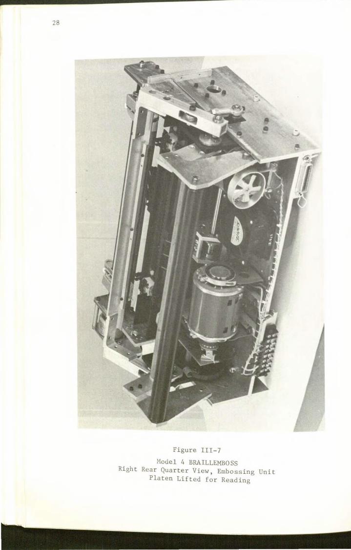
The Model 4 BRAILLEMBOSS
For time sharing or interactive computer operation it is necessary
to read the braille as it is produced o r immediately afterward . The Model
4 machine therefore i s mounted such that the braille is produced with the
bottom of the page closest to the user a t elbow height . A lifting platen
enables the user to r ead the last cell embossed (when the machine is quies-
cent) without moving the paper .
The line length of the Model 4 was increased to 42 cells to enable
an 80 column Hollerith Punched Card (IB~ card) to be printed on two lines
instead of t hree lines. Except for changes dicta ted by t lw 1 i ne length , lift
ing platen and cabine t, Models 3 and 4 are the same.
Figures III-6 and III- 7 a r e r ear quarter views of the ~1odel 4 . With
the platen lifted and with the platen in the emboss position to 1 ift the
platen ,
platen .
grasp the bar handle, lift it up and to the rear .
The Second Proto tyee
The Second Prototype was the first unit to incorporate a lifting
It has a line 1 th f eng o 38 cells instead of 42 eel Is . iS Its cabinet
made from Acme slotted when angle to permit easy change during thL' early tests
the man- machine interface for tl1e Model The line leO! 3 was being investigated . d b 4' 5·
an ca inet are the only differences to distinguish it from the other Model

Figure III- 6
Hodel 4 BRAILLEMBOSS Right Rear Quarter View, Embossing Unit
Platen in Embossing Position .
27
28
Figure III-7
Model 4 BRAILLEMBOSS Right Rear Quarter View, Embossing Unit
Platen Lifted for Reading
29
·' 1 .I ... ... ·' t h ll ... l. { l ... I n .., t 1 1 u t l. "' I t <. h ,, •, I < > g '
\I "- \ () U ) 1//)\ II Il l 1 11 0"- I "- I > I ) I I I I () I ' \t I "- I < I "- I I I<
.!').! '' '''" \/1((/, ( ~I Ill h I I t/ g t , '\J tl \ \ 11 t /1 II ' t I I \ ().!Jo.~.!
APPENDIX Ill
BRAILLER CHARACTERISTICS:
OUTPUT : Fan-Fold Paper ll inch x 11-1/2 inch pages 25 lines of Braille per page 28 lines per page 38 cells of Braille per line
MACHINE FUNCTIONS :
DlPUTS
Emboss. Embosses 0 to 6 dots in a 2 x 3 array per operation Time required: 62 . 5 milliseconds
Line Feed: ~aves paper one line . Time required: 100 milliseconds
Automatic Line Feed: ~1oves paper one line after 38th cell is embossed , either space or dots . Time required: 140 milliseconds including time to emboss
38th cell . Carriage Return : Spaces to end of line and Auto Line Feeds
Time required: (38-N) 62 . 5 + 140 milliseconds. Where N is the cell number in line 1 . . 38
End of Page: Line Feeds to the first line of next page . Time required: (29-H) 125 milliseconds where M is the line
number , 1 ... 28
Exerciser: Prints selected patterns for test purposes .
EQUIDOT -- Prints all possible combinations of 6 dots
BIDOT -- Prints selected dots every 2N th time where N = 1 , 2 , 3 , or 4 .
~anual : Prints selected dots either singly or multiples from control panel switches .
Tape Reader: Prints from special Braille coded 8- level paper tapes using a Friden SP-2 motorized tape reader .

30
CODES :
Teletype : Prints from a t e l e t ype through a code converter or translator.
DOTSYS. Converts to coding used in DOTSYS teletype transmission to brailler input code .
ONE- CELL . Converts ASCII(63 ) to a one-cell braille equivalent in brailler input code .
Keyboard : Prints from an external keyboard using Perkins Brailler keyboard arrangement.
Levels 1 through 6 are embossed as dots 1 through 6 if level 8 (machine function) is zero .
Level 7 is used as an even parity bit (for certain applications).
Level 8 indicates machine function
Carriage Return Levels 1, 2 , 3 , 8
End of Page 1, 2 ' 3, 7, 8
Line Feed 1, 2 , 3, 7, 8
Snace 7' ~
6 Augus t 1969.
Pll Y~

:>1. I . T . HIGH SPEED BRAILLE E}1BOSSER (cant . )
PHYSICAL PLA...~NING
I I
I 1--Lf I I
I I
I /
, .. /
Front PLA..\ VIE\..'
31
OPcembP r 30, 1969
POWEP. REQUTRE~1El'<TS
11 7 Volts 60 cycle AC
0 5 kva .
Height 62 inches
32
M.I.T. BRAILLEMBOSS CHARACTERISTICS (cont'd) 8 June 1970
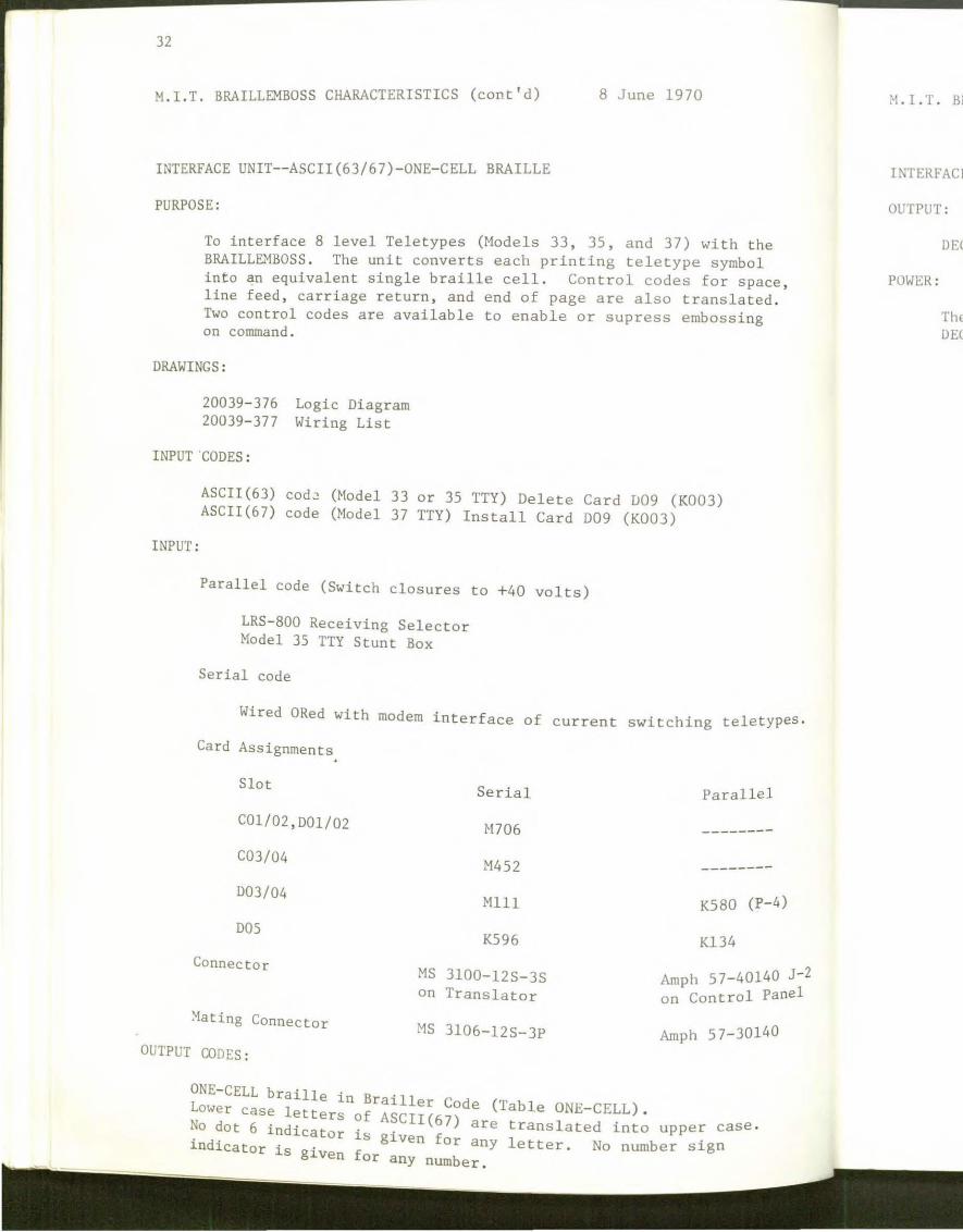
INTERFACE UNIT--ASCII(63/67)-0NE-CELL BRAILLE
PURPOSE:
To interface 8 level Teletypes (Models 33, 35, and 37) with the BRAILL&~BOSS . The unit converts each printing teletype symbol into an equivalent single braille cell. Control codes for space , line feed , carriage return, and end of page are also translated . Two control codes are available to enable or supress embossing on command .
DRAWINGS:
20039- 376 20039- 377
INPUT CODES :
Logic Diagram Wiring List
ASCII (63) cod~ (Model 33 or 35 TTY) Delete Card D09 (K003) ASCII(67) code (Model 37 TTY) Install Card D09 (K003)
INPUT :
Parallel code (Switch closures to +40 volts)
LRS- 800 Receiving Selector Model 35 TTY Stunt Box
Serial code
Wired ORed with modem interface of current switching teletypes .
Card Assignments
Slot
C01/02,D01/02
C03/04
003/04
DOS
Connector
~ating Connector
OUTPUT CODES:
ONE-CELL braille in B .11
Serial Parallel
H706 --------
M452 --------
Mlll K580 (P- 4)
K596 Kl34
MS 3100-12S-3S Amph 5 7-40140 J-Z on Translator on Control Panel
MS 3106-12S-3P Amph 57-30140
Lower 1 ra1 er Code (Table ONE-CELL) case etters of ASCII(6 ) •
No dot 6 · d. 7 are translated into upper case· 1n lcato · · i d. r 18 glven for any letter No number sign n lcator is given for .
any number.
1•1. I. T . Bl
INTERFACI
OUTPUT:
POWER:
DEC
The DEC
:•1 . I. T. BRAILLEMBOSS CHARACTERISTICS (cant' d)
INTERFACE U:-.<IT--ASCII (63/ 6 7) -ONE-CELL BRAILLE (cant ' d)
OUTPUT:
POWER :
DEC K-series gate expander outputs for code levels l through 8 .
The power is furnished by the brailler electronics through output cable DEC BC02S-3 .

34 T BRAILLEMBOSS CHARACTERISTICS (cont ' d) M. I. , 8 Jun~ 1970
Table ONE-CELL
I I f""- r ... L.. ...~ \.,. .... E ASCII(63) ; __ ,r.-.. .::. ~ .J-v .:..!...~ I ,. !
--~-----:---:::---=2-::--~-~1 SYXBOL . or~ I • 2 3 4. ~ 5 6 I 7 6 5 4 3 1 J j : v- I J. 0
~·-o--o-o--1-o--o--c-: oa l -~-~77 ! 1 : 1 • · 1 1':...._-=l=--=1=1
7 8 I
0 0 0 ·1 0 0 1 : 09 I 3 77 i 1 l 1 1 1 1
1,_' 0~..:::.0_0~-=1'---.::..0--=1=---=-0-! CA ! 305 11 I) _f)_'~ 0._.::..1---=1'-
1 0 0 0 1 0 1 1 I OB I ! 3 77 I : 1 1 . : 1 l 1 i.....:::..--==---=--=---==---=---=--: ,_,,___ __ --.J.-----I I ! I
l l l 0 0 0 1 1 0 0 ICC i I~:F_-----': 3~_1 _1_)._!.:_ ... ·. 0
! o o o 1 1 o 1 !oD! CR . :-n1 ', o " " ." f1 0 1 ~--==--~~--==--~~-·=~~r_..:::.~-- -~-~_::;......
ll-..::..0 ---=0---..:0::__.=..1---=1:..__=-1 _:::0--:...:! O:...:.E.:.... 11----+-~-...:...,-:...:' 7~ -----==--- 1 , .1.
!o o o 111 1ioFf j377ll 1 1 1 1 1 1
0 1 0 0 0 c I .------~~-~~. -------------~--~
0 : 20! SP/\CE . 3"0 ! " ') " ') 0._=-l ~1---!; 0 1 0 0 0 0
1 i 211 ! G 5 f) I 0 ==1==1 . O:__:l:___:O:..,..__;Oo_;jl :-.:.o_=-l--=o=---=-o--..:o::..._-=--=::o_J'~~22. ·· · 121 l o_...::.o_.::..C_'>~· 0 .!. o
I
J_0--.:1:::__..:.0_0=--...:::0:.__~1-=-;.-=..:.+-.:._'1-- . 0 71. I 0 , .. l I l , L 0 0~
0 0· _o_1_..:.o_o=---=1=--..:::..o_::_J.....::._.....__s;_· _ c 53 j_~ ~ o 1 ' I ~-~~~. --- ;
0 1 0 0 1 0 l j 25! % 1 51 ! 1 f) 0 1 : ') 1 1 'J--i 0 1 0 0 1 1 I • o'. --'---==---=--.......:::..__::.__.=,1_0~:_:;2 6 ! " . , 1 1 0 l i
I ' I i - _0 _1 __ 0 __;:0:.__..::.1 ___:1:::.._..=1~( =...:.2 7 I l 0 l, ! Q 0 1 f) I 0 0 l 0 I
1- . ~_..- ---~ : • I
:--'-0 --=-1---=0-...::1::___0~..:.!...0~0~· 2~ ~-~_(j_J_()_? : 1 - _ 1_1)_j_l_ 1.~:;._--: _0--=1=--..:.0_1=--...:::0:..__~0--1~~_?? ~~Illi_o _,_1 1 : 1 1_;;:;..1 __
_ o _1_-=-o --=~.:::..0--=1=--~0-;_'12/\ ; ~·~ • 0 ,, , ! 1 0 1 0 , o O_j . -,--~-- I
o 1 o 1 o 1 1 ! 2:.: 1 -k I 1 5 ,, l o " 1 1 ! o , 1 ~ _CJ_..;::.1--=o:___=-1--==1~o::_:.:!.,o~~ 2 c I , ~>-2 -~ o- '> 1 To~ 1 o ! ' 0 1 0 1 1 0 J i 2') I --.- -- - - --- i ;---~_:_--=..--.....:::.._~-..::_f : __ Old, I 0 I
0 1 0 1 l 0 I 2E I I 1 0 0 ~ :---=---..::...~--.::.--.!:,--.::!__J . --.-9) ~ 0 " o 1 r 0
1 0 1 1 ] l i 2F l I I 0 lf, . f) (l 1 l ! 0 0 0 0 ! t I • I' I . ____ ,! • __ _
M. I. T. 1

M.I.T. BRAILLEMBOSS CHARACTERISTICS (cont'd) 35
8 June 1970
Table ONE- CELL
I I ASCII (63) : .. ~ m-m- CELL BRAILLE
··~~ 2 1 I. ;-SYMBOL j OCT I 1 2 3 /, ' 5 6
j J I l ~-----. - 0- 1--1- 0--0- 0--0- r;;-' \ () 1164 ! 0 0 1 0 1: 1
~~ 3 7 81 1 7 6 5
I I I ! I
_o=--=1:.__=--=o--=-a --=o-=1--~ 31 I 1 1. 1 o 2 i o 1 o o ! o o
1 0
1 0 I I I i
I 0 l l 0 0 1 0 :32 2 t 006 I 0 1 l 0 ·0 0
~-_1-_-_-1-~~o-_~-o_·-_~1·~~1~:~:3-=-3~~--~-~~:3~~-:~:o-=-2_-=-2_-.:,.-:!-:o~~l:~:o~~o~:!:l~~o:~:~~= 0 0
0 0 (
! 0 1 ] 0 1 0 0 : 34 4 ! 162 0 1 0 0 :1 ' 1 0 l -I
i 0 l 1 0 l 0 1 35 --·
; a 1 1 0 l 1 0 36 ' 137 '0 ~ 1 0 1 l ]
iO 1 1 o o o ! 38 I LQ 1 l 1 0 0 1 ~39 1 o 1 1 1 o 1 o ! 3A
! 0 1 1 1 0 1 l i 3B j
· o 1 1 1 1 o 0 1 1 1 1 0 1 l3D:
10 1 1 1 1 1
5 : OLI2 0 1
(J 1126 l 0 1 I !
7 i 066 ! 0 1
8
9
) ,,
I
0 0 lo 1 .') h 1 0
1 0
0
0
0
0
1
1
h ' io
i1
:1 . i1
lo
I . .1
11
0 1 1 1 1 i !
..1.. I
1 0 0 l I ~
0 1 0 I 1 0 0 I
I
1 1 0 I
0 0 0 l I
l 1 0 ! 1 0 0 I 1 1 0
1 0 0
0 1 0
0. 0 '
1 0
1 1 13F ? 1 ~~1 -~--------------.,--------~, ---~,-----~·-, ------.
1 o o o o o o 14o1 @ 110 · o o o 1 'o o
1 o o o o o 1! 41! A i 101! 1 o o o lo o 1 0
oo3 I 1 I I
1 0 0 0 0 1 0 42 n 1 0 0 !0 0 0 0 I
I '4" !1
I t 1 0 0 0 0 1 1 I .) c Oll 0 0 1 (0 0 0 0
lu1 I I
1 0 0 0 1 0 0 44 D 11 0 0 1 ll 0 1 0 ! 11
' J. 0 0 0 1 0 1 45 E 021 0 () 0
; I ~1 0 0 0
I 1 .
1 0 0 0 1 1 0 46 F 113 1 0 1 ·0 0 l 0 I
' I I
I ' 1 0 0 0 1 1 l 1L.7 G 033 '1 1 0 ] '1 0 0 0 I I -

36 M. I.T. BRAILL~OSS CHARACTERISTICS (Cont'd) 8 June 1970
Table O~E-CELL
Ascn (63) i I c. ·:-c~~- s~A:L:.E -~--------· C::'''V o• I ,, 7 6 5 "- 3 2 1 i ,- 1
' ·"' 1.. i oc: : . 4 • 5 6 7 8 ~
1 0 0 1 0 ~ 48 ! B I . 2_1_! 1 ___ 0_0 __ Ll 0 1 0
! 1 0 0 1 0 0 1 t 4 9 I 1 ! 0 . : _= 0__9 0 0
1 0 0 1 0 1 0 ! 4A I J 1 0
I 1 0 0 1 0 1 1 I4B I K 0 0
, 1 o o 1 1 o o ;~ r. :~_c7_l, ____ ~_o_o c 1 0 1 o o 1 1 o 1 ' 4~~ l·1s_l, 1_1_.r' o 1 o 1 0. 0 1 1 1 0 14E · " 0 0
_. :---L I
1 0 0 l 1 1 1 14 :· i 0 f) 0 1 0
1 0 l 0 0 0 0 i 50 I , I 0 0 0~ 1 0 1 0 0 0 1 i 51! ~ 1 0 1 0~ 1 0 1 0 0 1 0 l 521 0 j • 0 0 OJ
l l I I 1 o 1 o o 1 1 1 511 <; o 1 o~
I ' j l 0 1 0 1 0 0 ! 54 ! T 0 0 0 I
l 0 1 0 1 0 J 55 i t: 1 0 1 1~ 1 o 1 o 1 1 o ;)6 j v ~ 0 1 o o__, 1 0 1 0 1 l 1 l 57 '.{ 1 .
1 o 1 1 o o o ! ssl :.: o o~ 1 0 1 1 o o 1 1 ~a 1 1 1 0 ----==--.!.-~__;:;:_---=:...L?d..: t y
10 1 101 tOO 1 0 1 1 0 1
1 0 l 1 1 ()
1 0 1 1 ] 0
----------------~ () 0 1
-----------------------
1 0 0
1 Q_
0 Q_
1 1 0
37
~1 .t ., ., a <. h u ~ c t t s ln'>titut c () ( Tc<.hnol<>g)
\1. '- \ 01(} , 1/D.\ I ! VAL l ' A'f/0"- A ,,() J)f'.V/· 1. 01-'.\ll '-I < / . ,,I I . I< 2 9 2 1\ I a i II S I r e e I , C t:l l.tl b r i d g e , t\1 t:1 .< .5 t1 ,. h II \ l I I ' () 2 I -+ 2
BRAILLEMBOSS
A Braille Page Printer
The H. I . T. BRAILL~1BOSS1 is a braille page printer designed to emboss
braille at similar or faster rates than teletypes . The BRAILLEMBOSS accepts electrical braille-coded signals from a variety of sources and in turn produces braille pages. When operating. continuously , it produces a page of braille every 1.6 to 2. 0 minutes .
The BRAILLD1BOSS lines are 38 cells long . Each page has 28 lines with 25 lines for braille and 3 blank lines for the top and bottom margin. The paper used by the BRAILLE~1BOSS is 100 pound-basis manila fan-folded sprocketdrive paper . When the sheets are separated and the sprocket drive strips are removed at the perforations, each sheet is a standard 11 x 11 1/2 inches .
The heart of the BRAILLEMBOSS is the embossing heads, each head contains 6 embossing pins in the braille cell configuration and an interposer pin beneath each embossing pin . These heads are fastened to a chain and so arranged such that one head is always supported under the platen, a steel female die containing 38 braille cells .
Each embossing pin is spring loaded upward . If an interposer pin is held in, then the corresponding embossing pin produces a dot when struck by the platen . If the interposer pin is out, the corresponding spring loaded embossing pin is merely forced down by the platen and no dot is made.
Each interposer pin is controlled by a selector bar. There are 6 selector bars, one for each dot, with 3 on each side of the head . Each s elector bar is parallel to the head support track and is controlled by a solenoid (250 rna @ 40 volts) . When a solenoid is energized, the corresponding interposer pin in the active head is held in .
The heads are positioned by both a support track and a tooth that engages the escapement rack. The tooth is held against the rack by a spring driven by a torque motor. This combination supplies a constant force to keep the tooth engaged .
The escapement rack is composed of two one-half pitch racks displaced by one pitch length. The rack shuttles back and forth at right ang les to the head track and is driven by an eccentric. Each time the rack moves from one side to the other the head advances one cell. ~fuen the active head is in the last cell location, it closes an end-of-line switch us ed in the Carriage Return logic .
SAEDC TECHNICAL DESCRIPTION SHEET NO . 2.
38
BRAILLENBOSS , A Braille P"'ge Printer (cant' d ·) page two
The platen is supported by two pivoted arms and driven by cranks at both ends of the cycle shaft. The rack is also driven by an eccentric geared at one-half speed to the cycle shaft. The cycle sh~ft is driven by a 1/20 horsepower motor through a cycle clutch. Each t1me the cycle clutch solenoid is pulsed, the cycle shaft makes one revolution. The platen goes through one cycle, from top to emboss position, and back to top, while the rack moves from one side to the other side each time the cycle shaft revolves .
The fan-fold sprocket-drive paper is supported by two paper tractors mounted close to the head track and platen but on the output side . The paper tractors are driven by a Ledex Digimotor. Each time the Digimotor is pulsed (5 amps@ 40 volts), it advances the paper on braille line. A page register is also a part of the paper drive and provides one switch closure per page to enable a new page command to be accurately executed.
The emboss sequence is as follows. The electronics determine from the signals that a braille cell is tc be embossed. The cycle clutch is pulsed and the appropriate selector bars are energized . The embossing is performed as the platen reaches the bottom of it's excursion, the selec tor bars are released and the head is advanced as the platen reaches the half way point on it's upward travel. The space sequence is identical except that selector bars are not energized. When the active head is in the last (38th) cell, at the time the selector bars are released, an automatic line feed signal is generated. This provides an automatic carriage return at the end of the line. The paper is advanced and the next head becomes the active head in the first cell position.
The Carriage Return function is controlled by a flip-flop. When the Carriage Return flip-flop is set, a self-clocking series of cycle-clutch pulses are generated and the heads are stepped around . The automatic line feed signal when in the last cell resets the flip-flop and stops the heads s~ch that the active head is in the first cell location. The Line Feed s1gnal pulses the line feed Digimoto r.
, The End-o:-Page f~nction is also controlled by a flip- f 1 op . When the End- of-Page fli.p-flop 1s set, a self clocking series of line feed pulses are.g~nerated to step the paper. When the paper is stepped to the first line pos1.twn on a page, the page register switch resets the End-of-Page flip-flop .
. ~he electrical signals for the BRAILLE.'1BOSS are derived from three pr1.nc1.pal sources manual (. 1 d. 2
3 ' 1.nc u 1ng a keyboard) a paper tape reader , or a translator The rna 1 d ' ddi-. . · nua mo es are uses primarily for test or limited a
tlon ~ol b~~I.lle from other sources. The translator allows other devices such as m~ e h P or 35.teletypes, an IBM 2741, a card reader or similar devices to supp. Y t e electnc~l signals· A three connector adaptor has been made to permi.t paper tapes l.n other d I b er th h h . co es t Jan brai ller codes to drive the em oss roug t e appropri.ate translator.
1) 2) 3)
~IT BRAILL81BOSS Spe · f · · · · n F ·d 1 d 1 Cl. 1.cat1.ons. SAEDC August 19()9 with latest revlS 10 • ri. en .o e SP 2 Paper Tape Reader O~E-CELL Transla t BRA . 8
ors, ILLEHBOSS Inh~rface Units. SAEDC, TDS No. .
August 4, 1970.

39
1\-1 ·' ., .. ·' <.. h ll ., 1.: t t s ln-.r itufl.. o l l << hnnlog \
\/,\01<) . 1/D\ Ll . lll ..-tr/0 ' l'f) ()fl/10!>\11'1 (/,Ill< 2 ') 2 . \1 , , I II \ I ,. t (' I • c <I Ill b ,. ; d g l' • ' " I I ' ' II ( h II ' ' I I ' (I 2 I -1 .!
DOTSYS
A Braille Translation Program
In 1964 the XIT SAEDC undertook the systems design of a programming compl ex adapted to a more ambitious and flexible braille utilization system, than had previously existed . 1 The system was dubbed DOTSYS (the DOT SYStem) and is described in some detail in the Pr oceedi ngs of Brai ll e Research conferences.2 . 3 and by Goldish4 .
DOTSYS ability to translate teletypesetter (TTS) tapes into grnde II braille was demonstrated twice during 1966 . The fi r st demonstration converted news service tapes into brailler code punched paper tapes . These tapes were then run on the ~1IT High Speed Braille Embosser , the predecessor of the BRAILLE:-IBOSS , to produce the braille . The second demonstration converted tlw TTS punched paper tapes used to print a textbook into stereograph punched cards. These cards \vere sent to the American Printing House for the Blind where interpointed zinc braille plates were made on their card driven stereograph . The brail l e was then embossed in the standard fashion .
DOTSYS consists of a number of program co-routines or "boxes " each which manipulates the information being processed in response to computer directed requests from successive elements in the computation chain .
This segmented approacl1 to the programming of DOTSYS was predica t ed on certain projected advantages . Flexibility is achieved since new " boxes" can be introduced progressively into the system with but minor side effects on the rest of the system . Thus , new input media can be assimilated as it becomes available, the translation program can be upgraded, and new braille production techniques can be accommodated . Adaptation to computers of different sizes is facilitated since an overall processing operation can be segmented into blocks which fit the available computer , producing and storing intermediate results for batching operations . Finally , from a program writing and testing point-of-vie\.; , t he "box" approach divides a very big overall job into digestible portions which individuals can program separately while maintaining effective communication with their co-wo rkers , and the individual segments can be independently tested and debugged.
During the summer of 1967 , the necessary parts of DOTSYS were written or modified to permit compu ter translated braille to be generated remotely from the computer. The necessary Input/Output (I/0) boxes were written for a time-shared computer (CTSS, an IBM 7094 at MIT) .
The material to be brailled was typed into the computer by a typist using a model 35 KSR teletype. \.fhen the typist completed typing the material, (or when a maximum of 60 lines were typed), the typist , via a typed command, initiated the translation. The Grade II braille was sent to an liiT High Speed Braille Embosser through the teletype . (During the time the Embosser was printing braille, the Teletypewriter was printing meaningless hasiJ.) The braille is correctly paged and of the standard format.
SAEDC TECHNICAL DESCRIPTION SHEET # 3.

40
DOTSYS: A Braille Tranalatiun Program
page two
It was this system which was demonstrated at Perkins during the winter of 1968. The operation of the remote braille production system was taught to approximately 48 members of the upper school ~c1cul. ty. Enthusiastic approval of the concept around which the ~ystem wab_d~stgn~a -- the production of braille material by an individual who 1.s not famtltclr \..'l.th Grade II braille -was unanimous . Hany of the teachers were familiar with special forms of braille, such as the Nemeth mathematics code, yet understood only superficially the English encoding . Others could read it quickly, but were comparatively slow transcribers . Still others simply did not have time to mnke several braille copies themselves and were dissatisfied with the qua 1 i ty and necessary waiting period for volunteer supplied braille material . The most encouraging result of the demonstration was that well over half of those who used the equipment stated that were it available, they could continue to use it several times a month , even without any further modifications.
Development of DOTSYS was not continued further for several reasons . First, the program is in Fortran Assembly Language (FAP) for IB~ 704 and 709 computers. These computers are now obsolete and have been superceded by the System/360. FAP is a machine language and cannot be readily transferred between similar computers and cannot be used on the 360 series without complete reprogramming or by emulation (now not readily available).
At the time of the Perkins demonstration the then current version of Embosser could operate at only one-half teletype transmission speeds and then only with frequent attention of the experimenter.
These limitations have been overcome. DOTSYS II has been written in ~ higher level computer language, COBOL, a nearly universal language . This anguage is available on most large computers regardless of manufacturer .
Fur~her, the BRAILLB-1BOSS has been developed to the point where it works rel1.ably for long periods of time at MODEL 35 Teletype Speeds.
References :
1.
2.
3.
4.
5 .
~upres~, J .K. , Buamann , D.M.B . , Mann, R.W., "Towards ~laking Braille As ccess1.ble As Print", EPL Report DSR 70249-1, HIT , June 1968.
Proceedings - Braille Research and Development SAEDC MIT, November 1966 . Conf erenc..L', . · ,
Proceedings - Conference EDC MIT, May 1967 . on New Processes for Braille ~lanufacture , SA '
Goldish, L H "B -11 . · n and Use" Th . . : ral e In The United States. It ' s Product ion DistnbutlO
es1.s (S ~~ ) ' ' " ' ' Sloan School of Management, r1IT, February 1967·
Greiner W E "D ) Me h . , 1 . . , . evelopment of Braille For Class Room UsL•", fhesis (M.S . ,
c anlca Engl.neering (MIT) F b ' . e raury, 1968.
July 28 , 1970.

41
1\.1 .l ., ., .l <._ h ll ' c [ ( ., l n,titut<.: " I 1 <-<h ll ulng\
\I'-\ OU 'r " . Ill)\ I I 'AL l .-1"1/0 l' 1 "-.f) f)J I ' / I ()P ,\11 '- 1 c 1 '- 11 U 2 <) 2 • \I '' i 11 .\ f r <' t' f , ( ' ' 111 h r i d g <', t\ I " 1 1 , 1 , I• 11 1 , t t , ( 1 ..! 1 -4 •
BRAILLEMBOSS APPLICATIONS
1 2 The M.I.T. BRAILLEMBOSS ' is an automatic braille printer operated by
electrical signals derived from one of many possible sources . It can operate at speeds compatible with either TELETYPES or IBM 2741 computer terminals. The Model 3 BRAILLEHBOSS produces high quality braille of standard literary format . \-Jhen operating continuously , it produces a page of br aille every 1 . 6 to 2 . 0 minutes .
The initial use of the BRAILLEMBOSS was the production of sing l e copy (or a few copies) of computer translated Grade II literary braille . In this application, a typist unfamiliar with braille can produce Grade II braille merely by typing plain English text, including a few easily l earned format control cha racters , into the computer . Such a system has previously been demons5rated at Perkins Scl1ool for the Blind in Watertown , Massachusetts by William Greiner and a similar system is on-line at the Center at this time . The complete sys tem co~sists of the BRAILLEHBOSS, :-lodel 35 TELETYPE, braille translation program DOTSYS , and an IB~1 7094 timesharing computer at MIT known as CTSS . Applica t ions for this mode of operation include public schools with blind students and agencies producing a limited number of braille copies . In both cases the computer translated braille increases the number of people capable of preparing braille to include those who are not exper t Braillists.
Another application of the BRAILLEMBOSS is the sho rt run production of braille materials using punched paper tape as the s t orage medium . The BR.t\ILLEHBOSS has provision for a paper tape reader, Friden SP- 2 , as an input device. The punched paper tape for demonstrations has been prepared by several means . One demonstratiog project used tape punched on a modified Perkins Brailler by an expert Braillist . Another method of preparing paper tape is by typing on a special TELETYPE converted by Mr. Ray Morrison. Gr ade I braille tapes can be prepared by any typist, but an expert Braillist must be used to produce Grade II braille tapes . Still another method of gener ating tapes is by computer . 6 Each of these methods has been used and has been proven useful for particular applications .
Further , by being a braille page printer for the computer terminal, th e BR.t\ILLR~BOSS opens the doo r of time-sharing computer to the blind programmer. 7
The BRAILLE}fBOSS is connected to the TELETYPE page printer via a braille translator unit8 and it faithfully duplicates in braille the inkprint output of the TELETYPE page printer. The Model 4 BRAILLEMBOSS has a lifting platen such that the programmer can read the last braille cell produced without moving the braille copy . Several computers have been operated by blind programmer s using the BRAILLEMBOSS, including IBM 7094 , IBM 360/67 , Digi tal Equipment Company PDP-10 and the General Electric Time-Sharing Comput er Service.
SAEDC TECHNICAL DESCRIPTION SHEET NO . 5 .

42
BRAILLEHBOSS APPLICATIONS page two
Twenty (20) BRAILLEMBOSS units have been produced at the Center with the support of the John A. Hartford Foundation . Earlier development~l work was supported and continuing demonstrations are supported by the Social Rehabilitation Administration of the Department of Health, Education, and Welfa r e.
References :
1 . M. I . T. BRAILLEMBOSS Specifications . SAEDC, August 1969 (with later revisions as applicable).
2 . BRAILLEMBOSS , A Br aille Page Printer. SAEDC , TDS No . 2
3. Greiner, W. E. , "Development of a Braille System for Classroom Use." (S.H. Thesis, M. E. Department , M. I . T. ). Feb . 1968 .
4. DOTSYS , A Braille Translation Program . SAEDC , TDS No. 3 .
5. The American Revolution, A Short Run Braille Pamphlet Demonstration. SAEDC, TDS No. 7.
6 . Conversion Table, Inches to Millimeters : A Braille Computer Generated Mathematical Table. SAEDC, TDS No . 10 .
7. Lichstein, M. L., Braille Computer Output. (M.I.T. - SAEDC). August 1969.
8. ONE-CELL Braille Translators , BRAILLEMBOSS Interface Units . SAEDC TDS No . 8.
July 29, 19 70

1
No. 8 .
43
Ma'>'>a<..hu~ct t s l n'> t itutc () f I ~ < h n <> I o g ,
\1 '\OU)- / 11 0\ I.V/ I/. l ' A'/ 1 0 A"-0 V/. V /1 OP ,\11 '1 ( I' II U 2 <) 2 I \1 <f i II .\ I r t! t: I , C a Ill b r i d g t! , 1\ f a l ~ a t /) II ' t · I I ' () 2 I -1 .!
A Pamphlet , "The American Revolution", A Short Run Braille Production .
One application of the MIT BRAILLEMBOSS is the short run braille production where only a few copies of a specialized work are required. Brailling of the pamphlet, "The American Revolution" presented an opportunity to demonstrate this application .
The BRAILLEMBOSS in the present state of development can routinely produce a page of braille every 1 . 0 to 2 . 0 minutes given the proper input signals . At the time of this demonstration only ~lachine #6, an experimental unit was available . This was a unit from the original braille production. All of the specified changes in the BRAILLEMBOSS required for improved accuracy, had been incorporated on this machine when the demonstration was performed . The only form of input available for this machine was punched paper tape.
The Howe Press of the Perkins School for the Blind has a paper tape punch controlled by a modified Perkins brailler . The pamphlet was brailled essentially the regular way on this braille writer by a Stereograph Operator at the Howe Press while at the same time a punched paper tape containing the braille codes was being generated . The paper tape was then hand edited and made into tape loops, each containing a single page .
The tape l oops were individually run on the High Speed Braille Embosser (BRAILLB1BOSS). The section of the pamphlet reproduced contained 32 pages of braille , and 25 copies of each page were reproduced for a total of 800 pages. The total BRAILL~1BOSS operating time was 20 hours spread over six working days .
Fifteen copies were given to Perkins Upper school students for their examination and use. The students were asked to record and report every error found . Several errors we r e spotted that existed in every copy. These errors which escaped detection in the tape editing process were later discover ed in the tape . Sometimes weak cells occurred in the last cell of a line. This was corrected in the redesign of the BRAILLEMBOSS , but was not incorporated in the experimental machine . Eleven random errors were discovered; one random erro r per 43 .6 pages , or 24 errors per million characters .
Other methods could be used for both input data preparation and storage . Relatively simple digital magnetic tape units are now available and could be used . A time-shared computer could be used to edit, translate into Grade II, determine the line and page division, and control the BRAILLEMBOSS directly.
This program demonstrated the application of the BRAILLEMBOSS for the production of a limited number of braille copies . The usual process of braille duplication requires the preparation and use of zinc or iron embossing plates to produce braille . However this demonstration showed that a single punched paper tape could be used to • produce several copies of the material, thereby substituting one paper tape for many zinc embossing plates. The program also demonstrated one way the BRAILL~tBOSS fills the gap between the large-run braille printing system and the hand-transcribed braille
production . Technical Description Sheet No . 7 September 28, 1970.


45
1'\1 " ., ., ·' (_ h " ., c l l • J . f ~ n ., l 1 t u t c o '1 ' c <- h n o I o g ~
\ 1 "- \()U) 1/D\ l : I 'ALl ' A 'JJOJ'\. A ,'\.IJ Dli VFf. / . OP t\lf. "- '1 ( / .'\. 'J/ .1< 2 <J 2 ' \1 a i II \ I r t' t' I , C Ll Ill b r i c/ g t' , }\ J a l .\ L'l c b 11 , <' I I , () 2 I -+ 2
ONE- CELL Br aille Translator s BRAILLEMBOSS Interface Units
The M. I. T. BRAILLEMBOSS1
requires electrical signals in the bra iller code to drive the BRAILL~1BOSS . The various information transfer codes, while most are in a similar forn~t to the brailler codes, cannot be used directly to drive the BRAILLEMBOSS as the resulting braille symbols would have meanings completely different than that commonly used. A translator unit is required to map the input codes into the brailler code .
The existing Grade I or Grade II literary braille codes are inadequate for computer programming for at least two reasons. First , several of the s ymbols required in computer progr ams , plus , equals , etc ., are simply not defined in literary braille . They are written out when required. Secondly, format is very important in computer programming , therefore it is necessary that there be a one- cell braille- equivalent for each inkprint character used in the computer character set. The resulting code--developed in consultation with several people--uses the same characters for the alphabet as does literary braille, the lower four dots in the same combination as previously for the numbers , just like the Nemeth convention, but without the number sign and then the remaining characters in the 63 character ASCII character set are defined with the least ambiguous braille codes representing the more important inkprint characters .
There is an additional requirement on the translator , that of matching the electrical requirements of both the input device , a TELETYPE for example , and the BRAILLEMBOSS. With a TELETYPE these inputs can be either switch closures on each code level or a serially coded current switching waveform . With other input devices still other input s may be used which the translator must match .
Several different types of translators2
have been designed, built, and operated. One of them is the "ASCII(63)/ASCII(67)-0NE-CELL Braille Translator ." This translator is designed to connect either a Model 33 , Model 35, or ~1odel 3 7 TELETYPE to the BRAILLEMBOSS . It has the ability, by choice of cards in the input section of the translator, to receive either the current- switching waveform or switch closures on each code level from either a ~1odel 35 "stunt box" or from an LRS 800 Receiving Selector . This translator also has the ability to map the lower case letters into the upper cas e letters such that a Model 37 TELETYPE can be used as an interface unit . Further, there is a remotely controlled on/off switch in the translator t o permit the computer to control embossing. This can be employed if embossing of only computer output is desired and not computer input.
SAEDC TECHNICAL DESCRIPTION SHEET NO . 8.

46
ONE-CELL Braille Translators, BRAILLE."'fBOSS Interface Units (cont'd .) Page two
Another translator, the ASCII(63)-0NE-CELL/DOTSYS translator, operates only with switch closures as inputs, but in two modes. The first translates the codes of the Model 33 or Model 35 TELETYPE into ONE-CELL braille while the second mode translates the special transmission codes used in DOTSYs3 into brailler code .
A third operational translator is for the Teletypewriter code (TTY) used in the United Press International wire service 5 level code. This translator presently accepts only switch closures from a tape reader . Designed, but not yet tested, is the required input circuitry to operate on the serial current switching waveform. This translator has been used in a Braille News Demonstration.4
Translators have been designed but not yet built for 6-level Teletype Setter (TTS) codes and for Hollerith punched cards. It is planned to design translators for IB~1 EBCDIC and IB:1 MT /ST codes . These will be reduced to practice as both time and budget permit.
References:
1 BRAILLEHBOSS, A Braille Page Printer. SAEDC TDS No . 2 and BRAILLEHBOSS APPLICATIONS SAEDC TDS No . 5.
2 M.I.T. BRAILLEMBOSS Specifications. SAEDC, August 1969 (with later revisions as applicable).
3 DOTSYS, A Braille Translation Program . SAEDC, TDS No . 3.
4 Braille News Demonstration. SAEDC TDS N , o . 12 .
July 17, 1970 .

47
M <l s ., a <: h ., ., ·· r t ~ I n . 1· 1 I 1 ~ ~ J ~ ttt ull: o l.<.lno og~
\/./'SOU) / 1/ 0'. !-" VA / L ' / l "J / 0" / ll, / J JJ I ! VF. I . OP 1\I/. ' 1 ( / _,, II U 2 9 2 ,\I a i 1J _<; I ret: I , C a 111 h r J d g t:, 1\1 <1 S ; n < b 11 , ._.. I I ·' () 2 I -1 2
CONVERSION TABLE , INCHES TO MILLIMETERS A BRAILLE COMPUTER GENERATED MATH~1ATICAL TABLE
An example of the use of the BRAILLEMBOSs1•2 as an output device of a
time-sharing computer was the production of a braille inches to millimeters conversion table . Such a table was recently prepared for a rehabilitation client of the Hassachusetts Commission for the Blind . The client has been trained to repair and rebuild foreign car automa t ic transmissions, but the only braille micrometers immediately available to him used inches . The transmissions are measured in metric units , i . e. , millimeters .
The table was produced using the CTSS (an IBM 7094) time-sharing computer3 running a FORTRAN II program, a teletype , punched paper tape reader, Translator and the BRAILLEMBOSS . The table was embossed in "one-cell" braille, developed for computer programmer use . This braille system has aone-to-one correspondence between the braille and inkprint characters . The inkprint characters are those used in the 63 character ASCII (American Standard Code for Information Interchange) character set used in the model 33 and 35 teletype .
Approximately one-half day was used in writing the 33 statement FORTRANII program . During this time four minutes of computer time was used to input the program from the teletype, compile, test , debug , and recompile it .
Punched paper tape was used as a buffer between the computer terminal and the BRAILLENBOSS for several reasons . The first was to make a machine readable master such that multiple braille copies could be produced without incurring the costs of additional computer and terminal time. In addition , it facilitated the writing of the program, since BRAILLEMBOSS timing considerations could be handled by an asynchronous punch paper tape system instead of special programming techniques not readily available in FORTRAN II. The BRAILLEMBOSS carriage return (CR) time is in general much longer than the time for the teletype and computer CR time, such that data would be lost during the time the BRAILLEHBOSS is executing a CR. All other functions of the BRAILLEMBOSS, except the end of page function, are accomplished in less time than with the teletype .
The compiled program was loaded into the computer, and the initial and final page numbers \"ere typed in, one page number per line . The Model 35 ASR teletype was set to the KT mode such that it produced both punched paper tape as well as printed copy. After the first page had been run on the computer, the end of the paper tape was loaded into the tape reader and the BRAILLEMBOSS started . The normal tape reader input to the BRAILLEMBOSS uses the Brailler code, not the ASCII used by the teletype; therefore, a cable adapter was used such that the tape reader was driven in its normal mode, but the output signals were fed into the teletype input jack of the BRAILLEMBOSS . The BRAILLD1BOSS
SAEDC TECHNICAL DESCRIPTION SHEET NO. 10 .
48
CONVERSION TABLE, INCHES TO MILLEMETERS (cont'd) Page two
running time was slightly longer than the terminal running time (in spite of the fact that the BRAILLEMBOSS is operated at a faster rate than the teletype) since each BRAILLEMBOSS carriage return took longer than with the teletype. The terminal running time used for this table was 2.5 hours, but the computer time used was 1 . 9 minutes. It also took approximately three hours to run the program and to emboss the first copy.
The table as produced by the BRAILLEMBOSS is embossed on one side only. If interpointed braille is desired, a suitable converter could be constructed such that the APH Automatic Sterograph at Howe Press could use the ASCII tapes to emboss the zinc plates for press use. Alternatively, the translator in the present embossing system could be used to drive a tape punch to produce paper tapes in the Brailler code used by the sterograph.
This demonstration has shown that the M. I.T . BRAILLEMBOSS, when properly interfaced with a time sharing computer, can produce mathematical tables, in Braille, of any mathematical functions that can be programmed into a computer.
1. BRAILLEMBOSS, A Braille Page Printer, SAEDC TDS #2 .
2. MIT BRAILLEMBOSS SPECIFICATIONS, SAEDC, August 1969 with Revisions
3 . ONE-CELL BRAILLE TRANSLATORS, BRAILLEMBOSS Interface Units SAEDC TD # 5 and 8.
July 20, 1970. Revised August 14, 1970.

49
Ma-,~a(.huscr r s In s r itutl: 0 ( 1· c c h n o I o g )
'>' 1: i' \ 0 U ''t' / J I DS T. V/ J I ll A T I 0 N A /'.. D D T; V /; L 0 P , \I / : -.., ·1 ( 1 /'.. 1 1 U 2 <.J 2 t\1 a i JJ .\ ' I ,. e e I .. C a 111 b r i d g e . 1\f a ~ , a t b 11 , < 1 1 1 () 2 1 -+ .!
BRAILLE NEWS DEMONSTRATION
For several weeks the SAEDC translated int o braille, a portion of the news stories carried by the United Press International news wire . The resulting braille copy was distributed to several blind people close to the Center. Through this service these blind professional people have been presented a new window t o the world -- a window very different from the one normally available to them . The news in depth was available to them when they desired it and in a form they could either skim or examine in detail at their conveni ence .
This has been done through the help and courtesy of Prof . J. F. Reintjes, R. S . Marcus, and R. B. Polanski of the Electronic Systems Laboratory of the Electrical Engineering Department of M. I . T. A UPI wire service 5 level page printer and reperforator was available for their use on a project (DSR 70149) sponsored by the American Newspaper Publishers Association.
The braille was produced by the M.I . T. BRAILLEMBOSS1 equipped with a TELETYPE Translator2 and driven by the paper tape which was punched on the UPI repreforator .
The page printer of the UPI wire service has a maximum line length of 72 characters while the line length of the BRAILLB-1BOSS is 38 cells . The BRAILLEMBOSS has an automatic new line feature such that when the 38th cell is embossed, the paper is advanced and the carriage returned (advanced) ready to emboss the succeeding character at the beginning of the next line . With the difference in line length almost every inkprint line is embossed on two braille lines, sometimes three . The word at the end of the first braille line will be divided arbitrarily in almost every case . A simple modification was installed on the BRAILLE}IBOSS such that the next space after N cells have been embossed causes a carriage return command to be generated . The number ~ was set to 32 cells but can be changed over the total range of 1 to 38 cells.
The carriage return command is treated differently by the wire service page printer and the BRAILLE~tBOSS. The \vire service page printer carriage return command does not advance the paper , only returns the carriage to the first printing location. It requires a separate command to advance the paper. The BRAILLEMBOSS treats the carriage return command as a new line command; i . e., returns the carriage and advances the paper .
These two differences produce a braille page with an unusual format . Each line of inkprint becomes a group of two or three braille lines separated by a blank line . This blank line can be deleted by modifying the BRAILLEMBOSS to require a line feed command after every externa~ carriage return co~~nd .. The braille continues across page lines also. A l1ne feed counter mod1f1cat1on similar to the cell counter could be added to start a new page after every
25 lines of braille.
SAEDC TECHNICAL DESCRIPTION SHEET NO . 12

50
BRAILLE NEWS DEMONSTRATION page two
The reperforator was operated each day, from the time ESL personnel arrived for work until the roll of paper tape (2000) feet was exhausted , generally about 5 hours . The tape was then run on the modified BRAILLEMBOSS equipped with the TTY translator. The BRAILLEMBOSS running time for a roll of paper tape was about 3 hours . A typical run produced approximately 200 pages of braille .
References :
1 . BRAILLEMBOSS Applications, A Braille Page Printer. (SAEDC, TDS No.5 )
2. ONE-CELL Braille Translators, BRAILLEMBOSS Interface Units. (SAEDC, TDS No . 8) .
Revised July 17, 1970 July 28, 1970
)SS ll )