final project report fingerprint enhancement and ... · final project report fingerprint...
TRANSCRIPT

Final Project Report
Fingerprint Enhancement and Identification
by
Adaptive Directional Filtering
EE5359- Multimedia Processing
Spring 2015
Under the guidance of
Dr. K. R. Rao
Submitted by
Vishwak R Tadisina
ID: 1001051048

Fingerprint Enhancement and Identification by Adaptive Directional Filtering
V. R. Tadisina
2 EE-5359 Multimedia Processing- Spring 2015
List of Acronyms:
1D- One Dimension
2D- Two Dimension
AFIS – Automatic Fingerprint Identification System
DC- Direct Current
ECTI-CON - Electrical Engineering/Electronics, Computer, Telecommunications
and Information Technology Conference
FBI – Federal Bureau of Investigation
FFT- Fast Fourier Transform
ICBA- International Conference on Bioinformatics and its Applications
ICPR – International Conference on Pattern Recognition
IEE – Institution of Electrical Engineers
IEEE- Institute of Electrical and Electronics Engineers
ISCV – International symposium on Computer Vision
LCNS- Lecture Notes in Computer Science
LPF- Low Pass Filter
MATLAB – Matrix Laboratory
MTF – Modulation Transfer Function
WACV- Winter Conference on Applications of Computer Vision

Fingerprint Enhancement and Identification by Adaptive Directional Filtering
V. R. Tadisina
3 EE-5359 Multimedia Processing- Spring 2015
Index
S. No. Chapter Name Pg. No
1 Introduction 4
2 Structure of a fingerprint 5
3 Algorithm for Fingerprint Enhancement 7
3.1 Normalization 9
3.2 Ridge orientation and Frequency 9
3.3 Directional Filtering 12
3.3(a) Butterworth Filter 14
3.3(b) Gabor Filter 15
4 Fingerprint Identification 17
4.1 Reference Point Location 18
4.2 Feature vector 19
4.3 Fingerprint Matching 20
5 Implementation 22
6 Scope of the Project 27
7 References 27

Fingerprint Enhancement and Identification by Adaptive Directional Filtering
V. R. Tadisina
4 EE-5359 Multimedia Processing- Spring 2015
1. Introduction A person can be recognized using different means of identification, but identifying
a person based on the biometrics has become important in current diverse businesses
like law enforcement, information system security, finance physical access control
etc. [4]. Fingerprint based identification is one of the most important biometric
technologies which has drawn a substantial amount of attention recently [4]. It is one
of the most reliable mode of authentication. It has been extensively used by forensic
experts in criminal investigations for decades [2]. The best aspect of fingerprint-
based identification is that the fingerprints of a person are unique and does not alter
with aging of an individual [1]. Law enforcement agencies developed a method to
manually match fingerprint. But this method is tedious and time taking. So in early
1960s automatic fingerprint identification system (AFIS) [2] was started. There are
different ways for obtaining a fingerprint. It can be done either by digitalizing the
image taken by ink or by using inkless scanners. So from this it can be observed that
the reliability of a fingerprint identification method depends mainly on the quality
of the extracted features (minutiae) [1]. Various processing stages are included in an
AFIS as shown in Fig. 1 [11]. Representation of fingerprints plays a vital role for
automation in AFIS. This representation should have the following properties.
1. Keep back the uniqueness of each fingerprint in various levels of resolution.
2. Distinct characteristics of a fingerprint can be estimated easily.
3. Easy to apply automatic matching algorithms.
4. Immune to noise distortions.
5. Effective and simple representation [11].

Fingerprint Enhancement and Identification by Adaptive Directional Filtering
V. R. Tadisina
5 EE-5359 Multimedia Processing- Spring 2015
Fig. 1 Stages in an AFIS [11].
2. Structure of a fingerprint: An image of the surface of the skin of the fingertip is called a fingerprint. It consists
of ridges (black lines) separated by valleys as shown in Fig. 2 [2]. The design of the
ridge in a fingerprint can be depicted as an oriented texture pattern with constant
prevalent spatial frequency and orientation in a local neighbourhood. Orientation
depends on flow pattern of the ridges, and frequency on inter-ridge spacing [2].
Fig. 2 Ridges and valleys in a fingerprint image [2]
Fingerprint Enhancement and Identification by Adaptive Directional Filtering
V. R. Tadisina
6 EE-5359 Multimedia Processing- Spring 2015
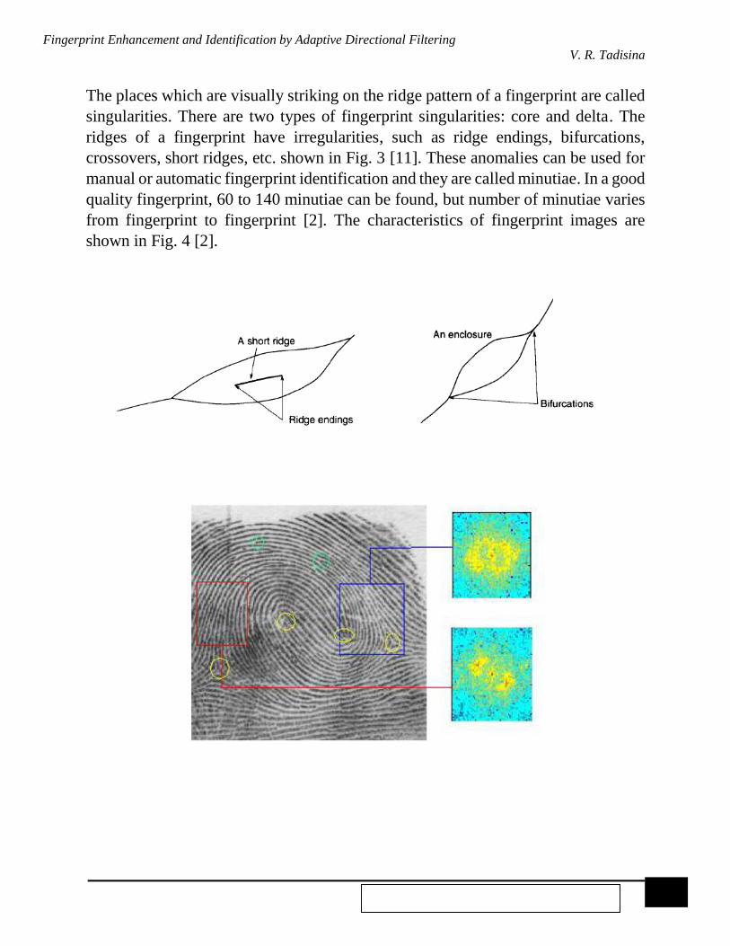
The places which are visually striking on the ridge pattern of a fingerprint are called
singularities. There are two types of fingerprint singularities: core and delta. The
ridges of a fingerprint have irregularities, such as ridge endings, bifurcations,
crossovers, short ridges, etc. shown in Fig. 3 [11]. These anomalies can be used for
manual or automatic fingerprint identification and they are called minutiae. In a good
quality fingerprint, 60 to 140 minutiae can be found, but number of minutiae varies
from fingerprint to fingerprint [2]. The characteristics of fingerprint images are
shown in Fig. 4 [2].
Fig. 3 Bifurcations and short ridges [11]
Fig. 4 A fingerprint image with marked singularities, minutiae and the frequency spectra corresponding to the local regions [2].

Fingerprint Enhancement and Identification by Adaptive Directional Filtering
V. R. Tadisina
7 EE-5359 Multimedia Processing- Spring 2015
3. Algorithm for Fingerprint Enhancement:
There are numerous algorithms for fingerprint enhancement [4]. An ideal algorithm
must increase the contrast between the ridges and valleys of a fingerprint for visual
examination or automatic feature extraction. In this algorithm during the processing
of each pixel, a local neighbourhood of that pixel is considered. Directional filters
are used as the ridges and valleys have well-defined frequency and orientation in the
local area. Here the filtering process is adaptive as the parameters of these directional
filters depend on the local ridge frequency and orientation. So in frequency domain,
directional filters are used for fingerprint enhancement [2].
The flowchart of the fingerprint enhancement algorithm is shown in Fig. 5 [4]. The
main steps of the algorithm include:
1. Normalization: To obtain a pre-specified mean and variance, an input
fingerprint image is normalized [2].
2. Local orientation and Frequency estimation: The normalized input fingerprint
image is used for computing orientation and frequency images [2].
3. Region mask estimation: Each block in the normalized input fingerprint image
are sorted out into a recoverable or an unrecoverable block to find a region
mask estimate [2].
4. Filtering: An enhanced image is obtained from the ridge-and-valley pixels in
the normalized input fingerprint image by using a bank of Gabor filters or
Butterworth filters that are tuned to local ridge orientation and ridge frequency
[2].
Fig. 5 A flowchart of fingerprint enhancement algorithm [4]
Fingerprint Enhancement and Identification by Adaptive Directional Filtering
V. R. Tadisina
8 EE-5359 Multimedia Processing- Spring 2015
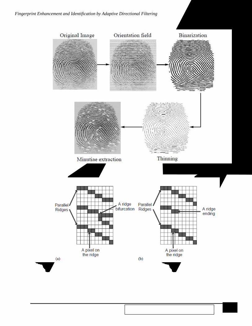
Fig. 6 Various stages in a fingerprint enhancement and identification algorithm [15]
Fig. 7 In (a) the pixel with three neighbours is a ridge bifurcation and in (b), pixel with only one neighbour is a ridge ending [15].
Fingerprint Enhancement and Identification by Adaptive Directional Filtering
V. R. Tadisina
9 EE-5359 Multimedia Processing- Spring 2015
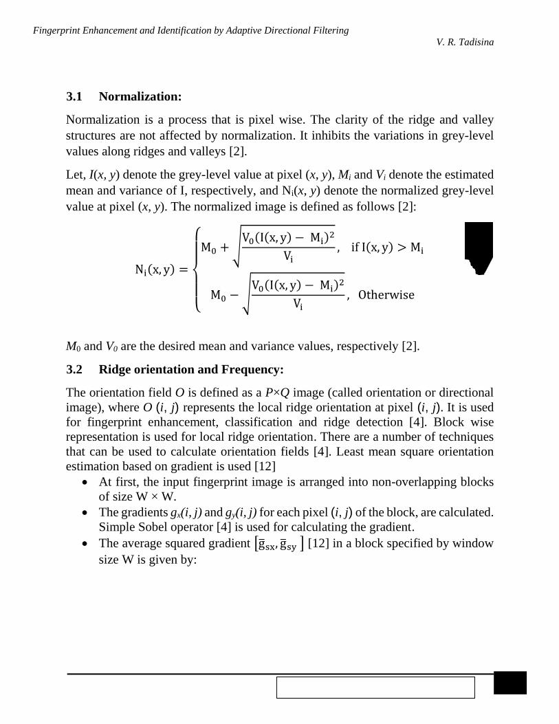
3.1 Normalization:
Normalization is a process that is pixel wise. The clarity of the ridge and valley
structures are not affected by normalization. It inhibits the variations in grey-level
values along ridges and valleys [2].
Let, I(x, y) denote the grey-level value at pixel (x, y), Mi and Vi denote the estimated
mean and variance of I, respectively, and Ni(x, y) denote the normalized grey-level
value at pixel (x, y). The normalized image is defined as follows [2]:
Ni(x, y) =
{
M0 +√
V0(I(x, y) − Mi)2
Vi, if I(x, y) > Mi
M0 −√V0(I(x, y) − Mi)
2
Vi, Otherwise
(1)
M0 and V0 are the desired mean and variance values, respectively [2].
3.2 Ridge orientation and Frequency:
The orientation field O is defined as a P×Q image (called orientation or directional
image), where O (i, j) represents the local ridge orientation at pixel (i, j). It is used
for fingerprint enhancement, classification and ridge detection [4]. Block wise
representation is used for local ridge orientation. There are a number of techniques
that can be used to calculate orientation fields [4]. Least mean square orientation
estimation based on gradient is used [12]
At first, the input fingerprint image is arranged into non-overlapping blocks
of size W × W.
The gradients gx(i, j) and gy(i, j) for each pixel (i, j) of the block, are calculated.
Simple Sobel operator [4] is used for calculating the gradient.
The average squared gradient [g̅sx, g̅sy ] [12] in a block specified by window
size W is given by:

Fingerprint Enhancement and Identification by Adaptive Directional Filtering
V. R. Tadisina
10 EE-5359 Multimedia Processing- Spring 2015
[g̅sxg̅sy
] =
[ ∑ ∑ [gx
2(u,v)−gy2(u,v)]
j+W2
v=j−W2
i+W2
u=i−W2
∑ ∑ 2 gx(u,v)gy(u, v)j+W2
v=j−W2
i+W2
u=i−W2 ]
(2)
The average gradient ϕ direction and dominant local orientation for the block are
given by:
Φ(i, j) = 1
2 tan−1
(
∑ ∑ 2 gx(u, v) gy(u, v)
j+W2
v=j−W2
i+W2
u=i−W2
∑ ∑ [gx2(u, v) − gy
2(u, v)]j+W2
v=j−W2
i+W2
u=i−W2 )
(3)
O(i, j) = Φ(i, j) +
π
2 (4)
as the angle of gradient is perpendicular to the ridge orientation a correction of 90
degrees is essential. Here blocks of size W × W for orientation estimation and
gradients gx and gy are used and calculated using Sobel operator [2].
To remove faulty ridge orientation values at the distorted and noisy regions
further smoothing is required on orientation values. It is done by converting
orientation image into a continuous vector field as shown in the Fig. 8, defined
as follows:
Ψx(i, j) = cos[2 O(i, j)] (5)
Ψ𝑦(𝑖, 𝑗) = sin[2 𝑂(𝑖, 𝑗)] (6)
where Ψx(i, j) and Ψy(i, j) are the x and y components of the continuous vector field
respectively.

Fingerprint Enhancement and Identification by Adaptive Directional Filtering
V. R. Tadisina
11 EE-5359 Multimedia Processing- Spring 2015
Fig.8 A continuous vector field formed by a local orientation image with a block of size W x W and center O (i, j).
Then the filter implementation [1] is given by,
Ψx′(i, j) = ∑ ∑ L(u, v)
WΨ/2
v=−WΨ/2
Ψx(i − uW, j − vW)
WΨ/2
u=−WΨ/2
(7)
Ψy′(i, j) = ∑ ∑ L(u, v)
WΨ/2
v=−WΨ/2
Ψy(i − uW, j − vW)
WΨ/2
u=−WΨ/2
(8)
O′(i, j) =
1
2 tan−1 (
Ψy′(i, j)
Ψx′(i, j)
) (9)
where L is a 2D LPF, W is the block size and WΨ × WΨ specifies the size of the
filter, Ψx′(i, j) and Ψy
′(i, j) are the x and y components of the continuous vector field
respectively after smoothing.
Local ridge frequency can be estimated by:
The grey values of all the pixels situated in each block are projected along a
direction perpendicular to the local orientation and computed. This projection
forms a 1D wave with the local extrema relevant to the ridges and valleys of
the fingerprint [2];

Fingerprint Enhancement and Identification by Adaptive Directional Filtering
V. R. Tadisina
12 EE-5359 Multimedia Processing- Spring 2015
The average number of pixels between two consecutive peaks in the 1D wave
generated above is denoted by K (i, j). The frequency ω(i, j) is computed as,
𝜔(i, j) =
1
K (i, j) (10)
in order to explain the above estimation a modeled fingerprint image instead
of the original raw fingerprint images can be used. A one dimensional (1D)
modeled fingerprint image is used. A finite rectangular wave (as seen in
Fig. 9) which is regarded as the simplification of the projection of all grey
values of the pixels in a direction, normal to the local orientation of the block
with local extrema corresponding to the ridges and valleys of the fingerprint.
Fig. 9 Finite rectangular wave as a modeled fingerprint [15].
3.3 Directional filtering:
In frequency domain local ridge spacing (ρ) gives radial component and local ridge
orientation (ϕ) gives angular component of a filter.
An ideal model of band pass directional filter in Fourier domain [1] can be expressed
using polar coordinates (ρ, ϕ) as

Fingerprint Enhancement and Identification by Adaptive Directional Filtering
V. R. Tadisina
13 EE-5359 Multimedia Processing- Spring 2015
H(ρ, ϕ) = Hr(ρ)Ha(ϕ) (11)
Hr(ρ) and Ha(ϕ) depend on local ridge spacing and local ridge orientation
respectively [12].
Fig. 10 Filter in Fourier domain (a) band pass (radial) component, (b) directional (angular) component, (c) combination of previous two [1].
Instead of applying appropriate filter for each pixel, a finite number of predefined
filters (regarding to finite number of discrete orientations, and fixed frequency) are
applied. The degradation of the filter image and number of filters must be small and
it can be obtained in following way:
1. Either an average ridge frequency or a constant is set empirically for entire
database set to eliminate filter dependence on local ridge frequency. So that the
context of the filter is determined only by the orientation
2. A fixed number (8 or 16) of orientation values by discretization is formed from
which a small number of directional filter components can be obtained.
The Fourier transform Pi, i = 1, 2, . . . , n of the filters is pre-computed and stored.
Filtering an input fingerprint image q(x, y) with dimensions C × D is performed as
follows [3]:
The 2D-FFT F(u, v) of input fingerprint q(x, y) image is computed,
𝐹(𝑢, 𝑣) =1
𝐶 . 𝐷 ∑∑𝑞(𝑥, 𝑦) 𝑒𝑥𝑝 [−𝑗2𝜋 (
𝑢𝑥
𝐶+𝑣𝑦
𝐷)]
𝐷−1
𝑦=0
𝐶−1
𝑥=0
(12)
here u= 0, 1, 2,…, 31 and v = 0, 1, 2,…, 31.
Each directional filter Pi is point-by-point multiplied by F(u, v), obtaining n
filtered image transforms PFi(u, v), i = 1, 2, . . . , n.
Inverse 2D-FFT is computed for each PFi(u, v) resulting in ‘n’ filtered images
pfi(x, y), i = 1, 2, . . . , n (spatial domain) [3]. For x = 0, 1, 2 …31 and y = 0, 1, 2 ...31.
Fingerprint Enhancement and Identification by Adaptive Directional Filtering
V. R. Tadisina
14 EE-5359 Multimedia Processing- Spring 2015
𝑝𝑓𝑖(𝑥, 𝑦) = ∑∑𝑃𝐹𝑖(𝑢, 𝑣) 𝑒𝑥𝑝 [𝑗2𝜋 (𝑢𝑥
𝐶+𝑣𝑦
𝐷)]
𝐷−1
𝑣=0
𝐶−1
𝑢=0
(13)
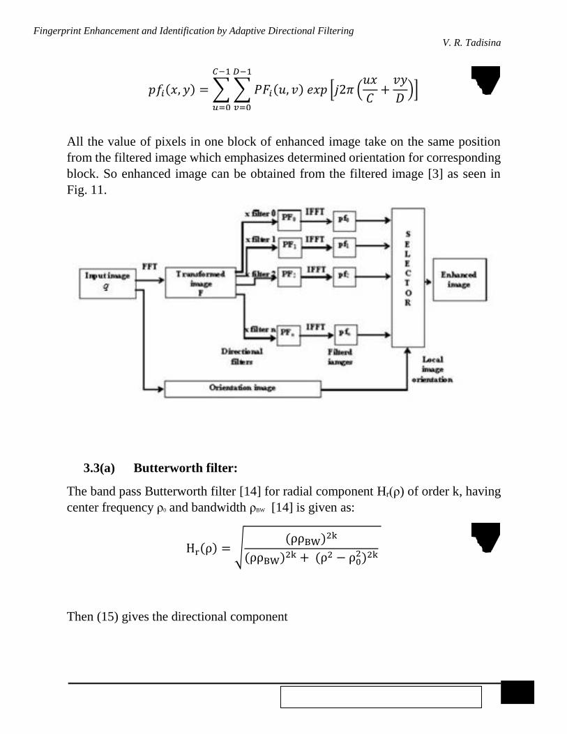
All the value of pixels in one block of enhanced image take on the same position
from the filtered image which emphasizes determined orientation for corresponding
block. So enhanced image can be obtained from the filtered image [3] as seen in
Fig. 11.
Fig. 11 Block diagram of a fingerprint enhancement algorithm [3]
3.3(a) Butterworth filter:
The band pass Butterworth filter [14] for radial component Hr(ρ) of order k, having
center frequency ρ0 and bandwidth ρBW [14] is given as:
Hr(ρ) = √(ρρBW)
2k
(ρρBW)2k + (ρ2 − ρ0
2)2k (14)
Then (15) gives the directional component

Fingerprint Enhancement and Identification by Adaptive Directional Filtering
V. R. Tadisina
15 EE-5359 Multimedia Processing- Spring 2015
Ha(ϕ) = {cos2
π(ϕ − ϕ𝑐)
2ϕBw if ϕ < ϕBw
0 Otherwise
(15)
where ϕBW is the angular bandwidth, and ϕc is the orientation of the filter [14].
Fig. 12 Butterworth bandpass frequency response
3.3(b) Gabor Filter:
Frequency-selective and orientation-selective properties of Gabor filters [6] make
them significant both in frequency and spatial domain. By simple adjustment of
mutually independent parameters, configuration of Gabor filters can be varied based
on different shapes, orientations, width of band pass and central frequencies. The
significant characteristic of a Gabor filter is, if properly tuned it can perform
frequency selective filtering on an image maintaining only regions of a given
frequency and orientation. This fundamental implications are used for research in
fingerprint image analysis and enhancement using this filter [4, 6].
An even symmetric Gabor filter general form [4] in the spatial domain is given by

Fingerprint Enhancement and Identification by Adaptive Directional Filtering
V. R. Tadisina
16 EE-5359 Multimedia Processing- Spring 2015
h(x, y, ϕ, Ω) = exp [−0.5 {(x
σx

Fingerprint Enhancement and Identification by Adaptive Directional Filtering
V. R. Tadisina
17 EE-5359 Multimedia Processing- Spring 2015
Fig. 13 An even-symmetric Gabor filter. (a) The Gabor filter with f = 10 and ϕ = 0. (b) The corresponding MTF [4].
4. Fingerprint Identification For fingerprint identification it is ideal to get representations of fingerprints which
are invariant with reference to scale, translation and rotation [22]. The scale variance
difficulty can be eliminated easily since most fingerprint images could be scaled as
per the dpi specification of the sensors. To remove the other two variance problems
a reference frame can be formed which is rotation and translation invariant [22]. The
translation invariance is handled by establishing a single reference point (core point).
This reference point is obtained based on the assumption that all the fingerprints are
vertically oriented. But practically the fingerprint images may be oriented up to
± 45º away from actual assumed vertical orientation. Cyclic rotation of the feature
values in the Fingercode in the matching stage handles this image rotation partially
[22].
4.1 Reference Point Location
Fingerprints have many perceptible landmark structures which can be used
collectively for finding a reference point [22]. The reference point or core point of a

Fingerprint Enhancement and Identification by Adaptive Directional Filtering
V. R. Tadisina
18 EE-5359 Multimedia Processing- Spring 2015
fingerprint is the point at which the curvature of the concave ridges is maximum as
shown in Fig.14.
Fig. 14 Concave and convex ridges in a fingerprint image when the finger is positioned upright [22].
After finding the smoothened orientation image in section 3.2. From equation (9)
compute E, an image containing only the sine component of O′ [22]
𝐸𝑝(𝑖, 𝑗) = sin(O′(𝑖, 𝑗)). (24)
A label image A(i, j) which indicates the reference point is initialized. Integrate pixel
intensities R1 and R2 for each pixel (i, j) in Ep(i, j) as shown in Fig. 15. Assign the
value of their difference in corresponding pixels to A(i, j) [22]
𝐴(𝑖, 𝑗) = ∑𝐸𝑝(𝑖, 𝑗) −∑𝐸𝑝(𝑖, 𝑗).
𝑅2
𝑝=0
𝑅1
𝑝=0
(25)
On a large database a reference point algorithm is used to empirically determine the
regions R1 and R2 [22]. The maximum curvature in concave ridges can be captured
making use of the geometry of regions R1 and R2. Find the maximum value in
A(i, j) [22] and assign its coordinate to the core, i.e., the reference point.

Fingerprint Enhancement and Identification by Adaptive Directional Filtering
V. R. Tadisina
19 EE-5359 Multimedia Processing- Spring 2015
Fig. 15 Regions for integrating E pixel intensities for A (i, j) [22].
After finding the core point the fingerprint image undergoes directional filtering in
eight different directions.
4.2 Feature vector
From [22] it is clear that a fingerprint image can be sectored into a total of 16 × 5 =
80 sectors (S0 through S79) whose core point [22] is the center of these sectors as
shown in Fig. 16.
Fig. 16 Reference point (x), the region of interest, and 80 sectors [22].
Let Fiϕ (x, y) be the ϕ - direction filtered image for sector Si. Now i ϵ {1, 2, 3,…79}
and ϕ ϵ {0º, 22.5º, 45º, 67.5º, 90º, 112.5º, 135º, 157.5º}. The feature value Viϕ [22]
is the average absolute deviation from mean defined as
𝑉𝑖𝜙 = 1
𝑛𝑖 (∑|𝐹𝑙𝑖𝜙(𝑥, 𝑦) − 𝑃𝑙𝑖𝜙 |
𝑛𝑖
𝑙=0
) (26)

Fingerprint Enhancement and Identification by Adaptive Directional Filtering
V. R. Tadisina
20 EE-5359 Multimedia Processing- Spring 2015
where ni is the number of pixels in Si and Pi ϕ is the mean of pixel values in a sector.
The average absolute deviation of each sector in each of the eight filtered images
defines the components of the feature vector.
4.3 Fingerprint matching
Based on the Euclidean distance between the corresponding Fingercode, fingerprint
matching is done. A Fingercode is a compact length code obtained by the filter-based
bank algorithm in [22] which uses a bank of Gabor filters to capture both local and
global details in a fingerprint. Reference point removes the translation variance
problem. To eliminate rotational variance the Fingercode is rotated cyclically [22].
The steps corresponding to single step cyclic rotation [22] of the features of the
Fingercode are described by (27)-(29). This corresponds to a feature vector which
would be obtained if the image were rotated by 22.5º. A rotation by R steps
corresponds to a rotation R × 22.5º of the image. A positive and negative rotation
implies clockwise and counterclockwise rotation respectively. The Fingercode [22]
obtained after R steps of rotation is given by
𝑉𝑖𝜙
𝑅 = 𝑉𝑖´𝜙´ (27)
𝑖´ = (𝑖 + 𝑚 + 𝑅)|𝑚| + (𝑖
𝑚) ×𝑚 (28)
𝜙´ = (𝜙 + 180º + 22.5º × 𝑅)|180º| (29)
where m is the number of sectors in a band, i ϵ {0,1 , 2,…79} and ϕ ϵ {0º, 22.5º, 45º,
67.5º, 90º, 112.5º, 135º, 157.5º}. Five templates are stored corresponding to the
following five rotations of the Fingercode: 𝑉𝑖𝜙−2, 𝑉𝑖𝜙
−1, 𝑉𝑖𝜙0 , 𝑉𝑖𝜙
1 𝑎𝑛𝑑 𝑉𝑖𝜙2 . To obtain
five different matching scores, input Fingercode is matched with these five
templates. The Fingercode corresponds to a rotation of 22.5º. But the fingerprints
are rotation invariant to small rotation within ± 11.25º. So another feature vector for
each fingerprint is generated which corresponds to a rotation of 11.25º. To generate
this, the original fingerprint is rotated by 11.25º. From the above rotated fingerprint
image five more templates are formed. So a total of ten templates for each fingerprint
[22] are formed as shown in Fig. 17. Fingercodes are generated for every 11.25º of
rotation of the fingerprint image this takes care of rotation invariance [21]. The
matching is done by taking into account the minimum matching distance score of
the ten stored templates [22]. Matching can be done with this minimum score which

Fingerprint Enhancement and Identification by Adaptive Directional Filtering
V. R. Tadisina
21 EE-5359 Multimedia Processing- Spring 2015
gives the best alignment of the two fingerprints. So the fingerprints are matched
using this minimum score.
Fig. 17 Examples of 640-dimensional feature vectors: (a) First impression of finger 1, (b) second impression of finger 1, (c) Fingercode of (a), (d) Fingercode of (b), (e) first impression of finger 2, (f) second impression of finger 2, and (g) Fingercode of (e), and (h) Fingercode of (f) [22].

Fingerprint Enhancement and Identification by Adaptive Directional Filtering
V. R. Tadisina
22 EE-5359 Multimedia Processing- Spring 2015
5. Implementation The performance of the proposed algorithm is tested using the fingerprint database
in [24]. The fingerprint images in this database are greyscale images. They have a
spatial resolution of 96 dpi and an amplitude resolution of 8 bits per pixel.
Dimension of each image is 640 x 480 pixels.
Normalization
Parameters for normalization are set to 100 for both M0 and V0. The ridge
orientations were discretized to 8 values (step 22.5◦). The original fingerprint
images and their normalized images are shown in the Fig. 18.
Fig. 18 a, b, c and d: Original fingerprint images; i, ii, iii and iv: Corresponding normalized images.
Ridge orientation and frequency
To determine ridge orientation, the input fingerprint images are divided into non-
overlapping blocks of size 8 × 8. Then the gradients gx(i, j) and gy(i, j) for each pixel
(i, j) of the block, are calculated by Sobel edge-emphasizing filter. The gradient and
edge detected images are shown in Fig. 19. Then all these gradient values are used
to compute average squared gradient and the average gradient ϕ direction. This
image is smoothened further using a 2D LPF to remove noise. Original fingerprint

Fingerprint Enhancement and Identification by Adaptive Directional Filtering
V. R. Tadisina
23 EE-5359 Multimedia Processing- Spring 2015
images and their orientation images are shown as quiver plots in the Fig. 20. A quiver
plot is vector plot which displays the direction of the ridges in the fingerprint as
arrows with components (u, v) at the points (x, y).
Fig. 19 (a), (b), (c) and (d) are original fingerprint images; (i), (ii), (iii) and (iv) are their respective Edge detected images; (1), (2), (3) and (4) are their respective Gradient images.

Fingerprint Enhancement and Identification by Adaptive Directional Filtering
V. R. Tadisina
24 EE-5359 Multimedia Processing- Spring 2015
Fig. 20 (a), (b) and (c) are original fingerprint images; (1), (2) and (3) are their respective orientation image quiver plots.

Fingerprint Enhancement and Identification by Adaptive Directional Filtering
V. R. Tadisina
25 EE-5359 Multimedia Processing- Spring 2015
Directional filtering
Bank of Gabor filters:
The inter-ridge distance in the fingerprint image is the main factor in determining
the parameters Ω, σx and σy, for optimal Gabor filter operation. The filter frequency
is the average ridge frequency Ω = 1/B where B is the average inter-ridge distance.
If Ω is too large spurious ridges are created in the filtered image, whereas if Ω is too
small nearby ridges are merged into one. The parameters are set to be Ω = 1/5, and
σx = σy = 4.0 [21]. Trade-off in selection of σx and σy is done based on empirical data
[5], so that the filter is robust to noise, but still can capture ridge information at fine
level. Eight different values for ϕ = iπ/8, i= 1, 2, …, 7 (0º, 22.5º, 45º, 67.5º, 90º,
112.5º, 135º, 157.5º) with respect to the x-axis are used. A 0º oriented filter
accentuates those ridges which are parallel to the x-axis and smoothens the ridges in
the other directions [21]. Filters tuned to other directions work in a similar way.
These eight directional-sensitive filters capture most of the global ridge
directionality information as well as the local ridge characteristics present in a
fingerprint [22]. Original fingerprint images and enhanced images obtained by
filtering with eight Gabor filter are shown in Fig. 21. To seize the whole global ridge
information in a fingerprint at least four directional filters are necessary [22], but in
order to capture local characteristics eight directional filters are required. So, four
directions are required for classification and eight directions for matching. Although
there is some redundancy among the eight filtered images, the verification accuracy
is improved by capturing both the global and local information [22].

Fingerprint Enhancement and Identification by Adaptive Directional Filtering
V. R. Tadisina
26 EE-5359 Multimedia Processing- Spring 2015
Fig. 21 (a), (b) and (c) are original fingerprint images; (1), (2) and (3) are the enhanced images obtained by directional filtering using a series of Gabor filters.

Fingerprint Enhancement and Identification by Adaptive Directional Filtering
V. R. Tadisina
27 EE-5359 Multimedia Processing- Spring 2015
6. Scope of the Project: The objective of this project is to apply the algorithm proposed in section 3 to
smudged and corrupted fingerprints to obtain enhanced images. This is done by
adaptive directional filtering in the frequency domain by using Butterworth [2] and
Gabor filters [1] for fingerprint image enhancement and also for removing noise.
MATLAB is used to normalize the corrupted fingerprints. Then the frequency and
ridge orientation are computed for each fingerprint image. After that the image is
filtered using directional filters. Here Butterworth and Gabor filters are used to
obtain an enhanced image. The quality of the images obtained from both filters is
compared visually. Fingerprint identification is done using MATLAB coding on the
filtered enhanced image by detecting reference point and storing a feature vector in
the form of a Fingercode in a data file. This data file is used as a database for
fingerprint matching [21].
7. References:
[1] A. M. Raiˇcevi´c and B. M. Popovi´c, “An Effective and Robust Fingerprint Enhancement by
Adaptive Filtering in Frequency Domain”, Facta Universitatis (NIS) Ser.: Elec. Energ.,
vol. 22, no. 1, pp.91-104, April 2009.
[2] J. E. Hoover, “The Science of Fingerprints: Classification and Uses”, Federal Bureau of
Investigation, Washington, D.C., Aug. 2006.
[3] B. G. Sherlock, D. M. Monro and K. Millard, “Fingerprint enhancement by directional
Fourier filtering,” IEE Proc. Vision Image Signal Process., vol. 141, no. 2, pp.87–94,
April 1994.
[4] L. Hong, Y. Wan and A. K. Jain, “Fingerprint image enhancement: Algorithm and
performance evaluation,” IEEE Trans. Pattern Anal. Machine Intell. vol. 20, no. 8,
pp. 777–789, Aug. 1998.
[5] A. Willis and L. Myers, “A cost-effective fingerprint recognition system for use with low-
quality prints and damaged fingertips,” Pattern Recognition, vol. 34, pp. 255–270,
Jan. 2001.
[6] J. Yang, L. Lin, T. Jiang and Y. Fan, “A modified Gabor filter design method for fingerprint
image enhancement,” Pattern Recognition Letters, vol. 24, pp. 1805–1817, Jan. 2003.
[7] L. Hong, A.K. Jain, S. Pankanti and R. Bolle, “Fingerprint Enhancement,” Proc. First
IEEE- WACV, pp. 202-207, Sarasota, Fla., Dec. 1996.
[8] T. Kamei and M. Mizoguchi, “Image Filter Design for Fingerprint Enhancement,”
Proc. ISCV’ 95, pp. 109-114, Coral Gables, Fla., Nov. 1995.
Fingerprint Enhancement and Identification by Adaptive Directional Filtering
V. R. Tadisina
28 EE-5359 Multimedia Processing- Spring 2015
[9] K. Karu and A.K. Jain, “Fingerprint Classification,” Pattern Recognition, vol. 29, no. 3,
pp. 389-404, July 1996.
[10] L. O’Gorman and J.V. Nickerson, “An Approach to Fingerprint Filter Design,” Pattern
Recognition, vol. 22, no. 1, pp. 29-38, Jan. 1989.
[11] N. Ratha, S. Chen and A.K. Jain, “Adaptive Flow Orientation Based Feature Extraction
in Fingerprint Images,” Pattern Recognition, vol. 28, no. 11, pp. 1657-1672, March 1995.
[12] Y. Wang, J. Hu and F. Han, “Enhanced gradient-based algorithm for the estimation of
fingerprint orientation fields”, Applied Mathematics and Computation, vol. 185, no. 2,
pp. 823-833, Feb. 2007.
[13] D. L. Hartmann, “Filtering of Time Series”, 2014.
[Online]. Available: http://www.atmos.washington.edu/~dennis/552_Notes_7.pdf
[14] S. Chikkerur, A. N. Cartwright and V. Govindaraju, “Fingerprint enhancement using
STFT analysis”, Pattern Recognition, vol. 40, pp. 198-211, Jan. 2007.
[15] R. Iwai and H. Yoshimura, "A New Method for Improving Robustness of Registered
Fingerprint Data Using the Fractional Fourier Transform", International Journal of
Communications, Network and System Sciences, vol. 3, no. 9, pp. 722-729, Sept. 2010.
[16] A. Sherstinsky and R.W. Picard, “Restoration and Enhancement of Fingerprint Images
Using M-Lattice: A Novel Non-Linear Dynamical System,” Proc. 12th ICPR-B,
pp. 195–200, Oct. 1994.
[17] E. Bezhani, D. Sun, J. Nagel and S. Carrato, “Optimized filterbank fingerprint
recognition”, Proc. SPIE 5014, Image Processing: Algorithms and Systems, vol. 2,
pp. 20-24, May 2003.
[18] Project Idea, EE5359-Multimedia Processing Course Website. [Online]. Available:
http://www.uta.edu/faculty/krrao/dip/Courses/EE5359/index_tem.html
[19] P. Salil, J. Anil and P. Sharath, “Learning fingerprint minutiae location and type,” Pattern
Recognition, vol. 36, pp. 1847-1857, Oct. 2003.
[20] MATLAB version 8.1.0.604, Release R2013a, The MathWorks, Inc., Natick,
Massachusetts, United States, Feb 2013.
[21] E. Zhu, J. Yin, G. Zhang and C. Hu, “A Gabor Filter Based Fingerprint Enhancement
Scheme Using average Frequency,” International Journal of Pattern Recognition and
Artificial Intelligence, vol. 20, no. 3, pp. 417-429, May 2006.
[22] A. K. Jain, S. Prabhakar, L. Hong and S. Pankanti,“Filterbank-Based Fingerprint Matching”,
IEEE Transactions on Image Processing, vol. 9, no. 5, pp.846-859, May 2000.
[23] A. K. Jain, S. Prabhakar and L. Hong, “A multichannel approach to fingerprint
classification,” IEEE Trans. Pattern Anal. Machine Intell. vol. 21, no. 4, pp. 348–359,
Apr. 1999.
[24] Fingerprint Verification Competition, The Biometric system lab, University of Bologna,
Cesena-Italy, 2004.
[Online]. Available: http://bias.csr.unibo.it/fvc2004/download.asp.
[25] FBI Fingerprint Database, Washington, D. C., United States.
[Online]. Available: http://www.fbi.gov/about-us/cjis/fingerprints_biometrics/iafis/iafis.
[26] K. R. Rao and S. Chakraborthy, “Fingerprint Enhancement by Directional Filtering”,
ECTI-CON, Hua Hin, Thailand, 16-18 May 2012.
[27] K. R. Rao, D. N. Kim and J. J. Hwang, “Fast Fourier Transform - Algorithms and
Applications”, Springer Science & Business Media, New York, 2010.

Fingerprint Enhancement and Identification by Adaptive Directional Filtering
V. R. Tadisina
29 EE-5359 Multimedia Processing- Spring 2015
[28] S. Chikkerur, C. Wu and V. Govindaraju, "A systematic approach for feature extraction
in fingerprint images", ICBA, LCNS, vol. 3072, pp. 344-350, 15-17 July 2004.
[29] K. Nilsson and J. Bigun, “Localization of corresponding points in fingerprints by complex
filtering”, Pattern Recognition Letters, vol. 24, no. 13, pp. 2135-2144, Sept. 2003.
[30] A. R. Rao, “A Taxonomy for Texture Description and Identification”, Springer Series in
Perception Engineering, New York, 2012.
[31] M. Kass and A. Witkin. "Analyzing oriented patterns", Computer vision, graphics and
image processing, vol. 37, no. 3, pp. 362-385, March 1987.
[32] Image Processing Toolbox User’s guide, The MathWorks, Inc., Natick, Massachusetts,
United States, March 2015.
[Online]. Available: http://nl.mathworks.com/help/pdf_doc/images/images_tb.pdf.
[33] L. Rosa, MATLAB Fingerprint Recognition Functions Code, L'Aquila, Italy.
[Online]. Available: http://www.advancedsourcecode.com/fingerprint.asp.