final-hamworthycombustion andycastell … · oxidation systems industrial dedicated teams of c 100...
TRANSCRIPT

Operational and Design Issues Faced byOperational and Design Issues Faced by Low NOx and Ultra Low NOx Burners
ANDY CASTELL – General Manager, The America’sTel: +1 832 300 2400
E il t ll@h th b ti
lmnopqE-mail: [email protected]
AGENDA
Statement of Intent
The 3 W’s???
•Corporate Overview
•Market Sectors•Market Sectors
What is Delayed Coking
Burner Design – Historical Requirement
Burner Design – Current Requirement
Factors for Consideration in Burner Design
Burner Design – Advantages of Staging Principals
Burner Design – Future Requirements
Burner Design – Next Generation Technology
Necessities for Meeting End User Future Objectives
lmnopqNecessities for Meeting End User Future Objectives
Questions??? 2

Statement of Intent
Hamworthy Combustion informs that the contents contained withinthis presentation, including all information and statements made,are not specific to any manufacturer type or model but are intendedonly as topics for discussion with the intent to simply raise thecriticality of certain information and data necessary to review thecorrect design, operation and function of Low NOx and Ultra LowNOx burners and how if not correctly interpreted this lack of clarityNOx burners and how if not correctly interpreted this lack of clarityin information can lead to incorrectly designed equipment which inturn could lead to a loss in furnace efficiency and overall
d ti f th f it lfproduction of the furnace itself.
The information contained within this presentation is of a proprietary nature and shall not be released to third parties
lmnopqwithout the prior written consent of Hamworthy Combustion.
3
Hamworthy Combustion Global Solutions, Local Delivery
WHO ARE HAMWORTHY COMBUSTION?
WHAT COMBUSTION EQUIPMENTS DO WE SUPPLY??
WHICH MARKET SECTORS DO WE SUPPORT???
THE 3 W’s ???
lmnopq4
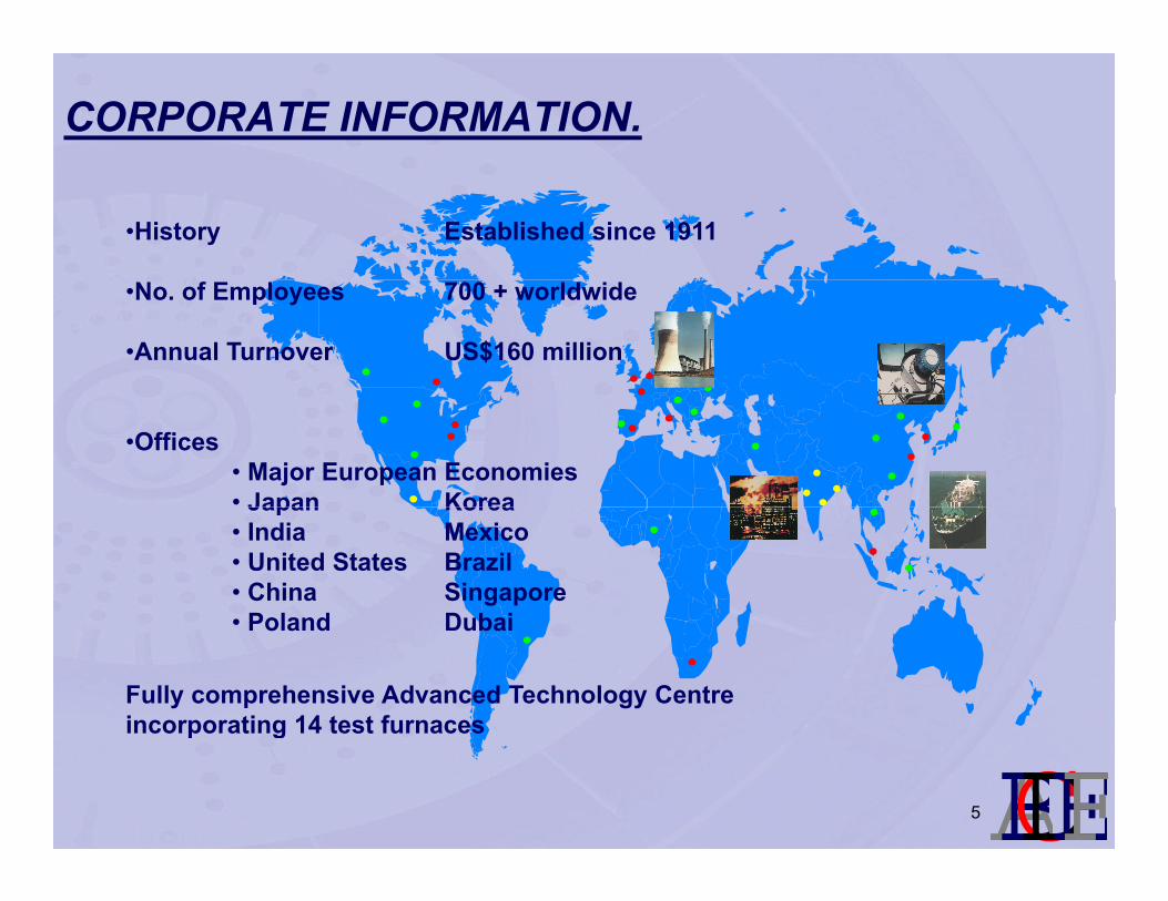
CORPORATE INFORMATION.
•History Established since 1911
•No. of Employees 700 + worldwide
•Annual Turnover US$160 million
•Offices• Major European Economies• Japan KoreaJapan Korea• India Mexico• United States Brazil• China Singapore• Poland Dubai• Poland Dubai
Fully comprehensive Advanced Technology Centre incorporating 14 test furnaces
lmnopqp g
5

MARKET SECTORS – CUSTOMER CENTRIC
Power MarineSales Contracts Commissioning Service Spares
Power
Sales Contracts Commissioning Service Spares
Marine
Power
TOS & Flares
Process
I d t i l
ThermalOxidation Systems
Industrial
Dedicated teams of c 100 people focussed on each sector: specialists 100% full time
& Flares
Process
each sector: specialists, 100% full time
Industrial
lmnopqWe are a true customer solutions provider in the highly specialised markets we serve
6
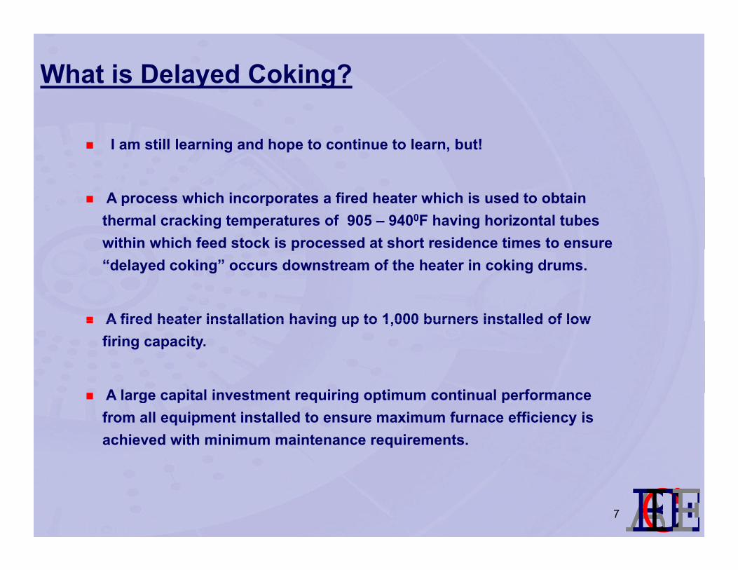
What is Delayed Coking?
I am still learning and hope to continue to learn, but!
A process which incorporates a fired heater which is used to obtain thermal cracking temperatures of 905 – 9400F having horizontal tubes within which feed stock is processed at short residence times to ensure p“delayed coking” occurs downstream of the heater in coking drums.
A fired heater installation having up to 1 000 burners installed of lowA fired heater installation having up to 1,000 burners installed of low firing capacity.
A large capital investment requiring optimum continual performanceA large capital investment requiring optimum continual performance from all equipment installed to ensure maximum furnace efficiency is achieved with minimum maintenance requirements.
lmnopq7
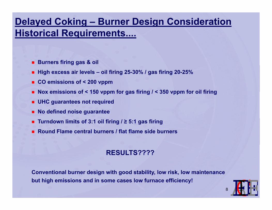
Delayed Coking – Burner Design ConsiderationHistorical Requirements....
Burners firing gas & oil
High excess air levels – oil firing 25-30% / gas firing 20-25%
CO emissions of < 200 vppm
Nox emissions of < 150 vppm for gas firing / < 350 vppm for oil firingNox emissions of < 150 vppm for gas firing / < 350 vppm for oil firing
UHC guarantees not required
No defined noise guarantee
Turndown limits of 3:1 oil firing / ≥ 5:1 gas firing
Round Flame central burners / flat flame side burners
RESULTS????
Conventional burner design with good stability low risk low maintenance
lmnopqConventional burner design with good stability, low risk, low maintenance but high emissions and in some cases low furnace efficiency!
8
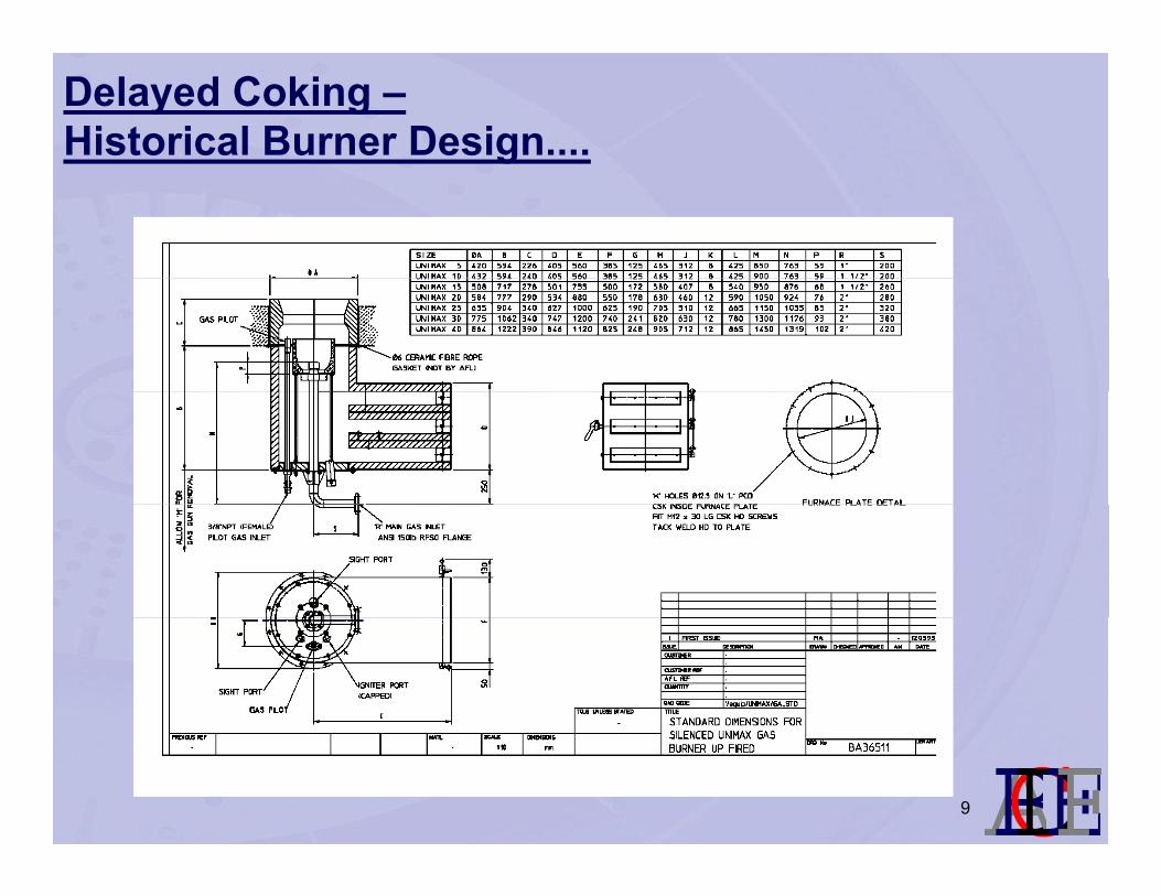
Delayed Coking –Historical Burner Design....
lmnopq9
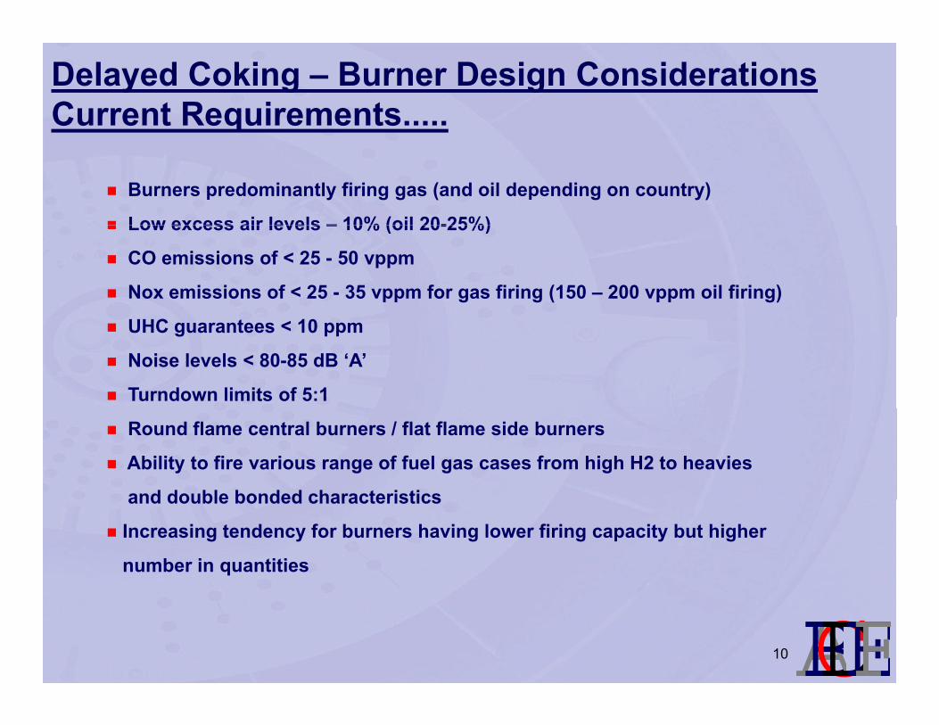
Delayed Coking – Burner Design ConsiderationsCurrent Requirements.....
Burners predominantly firing gas (and oil depending on country)
Low excess air levels – 10% (oil 20-25%)Low excess air levels – 10% (oil 20-25%)
CO emissions of < 25 - 50 vppm
Nox emissions of < 25 - 35 vppm for gas firing (150 – 200 vppm oil firing)
UHC guarantees < 10 ppm
Noise levels < 80-85 dB ‘A’
Turndown limits of 5:1
Round flame central burners / flat flame side burners
Ability to fire various range of fuel gas cases from high H2 to heavies
and double bonded characteristicsand double bonded characteristics
Increasing tendency for burners having lower firing capacity but higher
number in quantities
lmnopq10
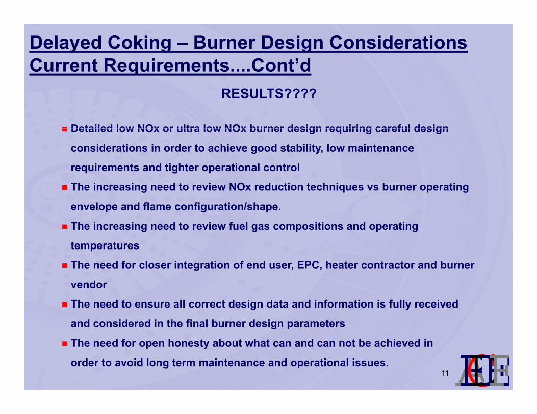
Delayed Coking – Burner Design ConsiderationsCurrent Requirements....Cont’d
RESULTS????
Detailed low NOx or ultra low NOx burner design requiring careful designDetailed low NOx or ultra low NOx burner design requiring careful design
considerations in order to achieve good stability, low maintenance
requirements and tighter operational control
The increasing need to review NOx reduction techniques vs burner operating
envelope and flame configuration/shape.
The increasing need to review fuel gas compositions and operating
temperatures
The need for closer integration of end user, EPC, heater contractor and burner
vendorvendor
The need to ensure all correct design data and information is fully received
and considered in the final burner design parameters
lmnopqThe need for open honesty about what can and can not be achieved in
order to avoid long term maintenance and operational issues.11

Low NOx and Ultra Low NOx Burners –Factors for Consideration
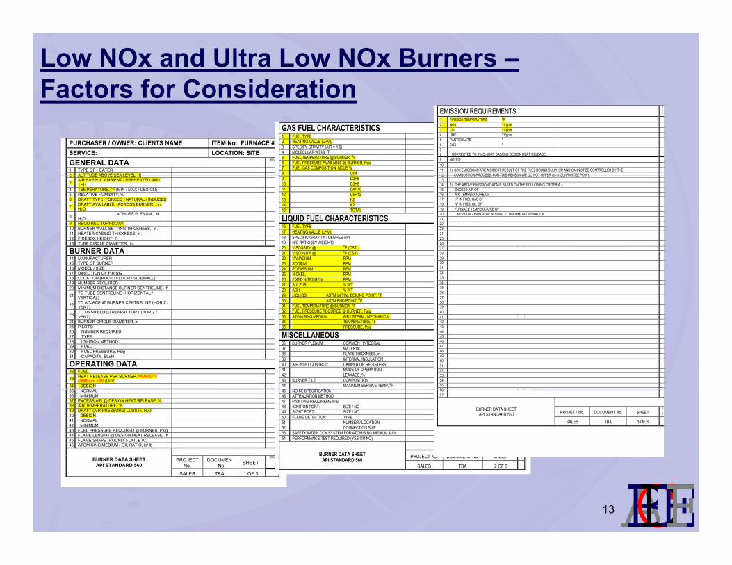
Receiving the correct and complete design data requirements, incl...
– Altitude above sea level clearly stated.
– Units of Liberation clearly stated.
– Maximum pressure drop across burner correctly stated.
– Design duty vs normal duty vs minimum duty fully reviewed
– Fuel compositions and conditions clearly stated.
Emissions requirements stated with no additional safety factor added– Emissions requirements stated with no additional safety factor added
lmnopq12
Low NOx and Ultra Low NOx Burners –Factors for Consideration
PURCHASER / OWNER: CLIENTS NAME ITEM No.: FURNACE # SERVICE: LOCATION: SITE
GENERAL DATA REV
1 TYPE OF HEATER 2 ALTITUDE ABOVE SEA LEVEL ft
GAS FUEL CHARACTERISTICS REV
1 FUEL TYPE
2 HEATING VALUE (LHV), 3 SPECIFY GRAVITY (AIR = 1.0) 4 MOLECULAR WEIGHT 5 FUEL TEMPERATURE @ BURNER, OF 6 FUEL PRESSURE AVAILABLE @ BURNER, Psig 7 FUEL GAS COMPOSITION, MOLE % 8 CH4
EMISSION REQUIREMENTS REV
1 FIREBOX TEMPERATURE OF 2 NOX * Vppm 3 CO * Vppm 4 UHC * Vppm 5 PARTICULATE * 6 SOX * 7 8 * CORRECTED TO 3% O2 (DRY BASIS @ DESIGN HEAT RELEASE) 9 NOTES: 10 11 1) SOX EMISSIONS ARE A DIRECT RESULT OF THE FUEL BOUND SULPHUR AND CANNOT BE CONTROLLED BY THE 12 COMBUSTION PROCESS FOR THIS REASON WE DO NOT OFFER AS A GUARANTEE POINT2 ALTITUDE ABOVE SEA LEVEL, ft
3 AIR SUPPLY AMBIENT / PREHEATED AIR / TEG
4 TEMPERATURE, °F (MIN / MAX / DESIGN) 5 RELATIVE HUMIDITY, % 6 DRAFT TYPE: FORCED / NATURAL / INDUCED
7 DRAFT AVAILABLE: ACROSS BURNER, . in. H2O
8 ACROSS PLENUM, . in. H2O
9 REQUIRED TURNDOWN 10 BURNER WALL SETTING THICKNESS, in. 11 HEATER CASING THICKNESS, in. 12 FIREBOX HEIGHT, ft 13 TUBE CIRCLE DIAMETER, in.
9 C2H6 10 C3H8 11 C4H10 12 C5H12 13 H2 14 N2 15 TOTAL
LIQUID FUEL CHARACTERISTICS16 FUEL TYPE 17 HEATING VALUE (LHV), 18 SPECIFIC GRAVITY / DEGREE API 19 H/C RATIO (BY WEIGHT) 20 VISCOSITY @ OF (CST)
12 COMBUSTION PROCESS, FOR THIS REASON WE DO NOT OFFER AS A GUARANTEE POINT.13 14 2) THE ABOVE EMISSION DATA IS BASED ON THE FOLLOWING CRITERIA :- 15 EXCESS AIR OF 16 AIR TEMPERATURE OF 17 H2 IN FUEL GAS OF 18 N2 IN FUEL OIL OF 19 FURNACE TEMPERATURE OF 20 OPERATING RANGE OF NORMAL TO MAXIMUM LIBERATION. 21 22 23 24 25 26 27BURNER DATA
14 MANUFACTURER 15 TYPE OF BURNER 16 MODEL / SIZE 17 DIRECTION OF FIRING 18 LOCATION (ROOF / FLOOR / SIDEWALL) 19 NUMBER REQUIRED 20 MINIMUM DISTANCE BURNER CENTRELINE, ft
21 TO TUBE CENTRELINE (HORIZONTAL / VERTICAL)
22 TO ADJACENT BURNER CENTRELINE (HORIZ / VERT)
23 TO UNSHIELDED REFRACTORY (HORIZ / VERT)
20 VISCOSITY @ OF (CST)21 VISCOSITY @ OF (CST) 22 VANADIUM, PPM 23 SODIUM, PPM 24 POTASSIUM, PPM 25 NICKEL, PPM 26 FIXED NITROGEN PPM 27 SULFUR, % WT 28 ASH % WT 29 LIQUIDS ASTM INITIAL BOILING POINT, OF 30 ASTM END POINT, OF 31 FUEL TEMPERATURE @ BURNER, OF 32 FUEL PRESSURE REQUIRED @ BURNER, Psig 33 ATOMISING MEDIUM: AIR / STEAM / MECHANICAL
27 28 29 30 31 32 33 34 35 36 37 38 39 40 41 )
24 BURNER CIRCLE DIAMETER,.in. 25 PILOTS: 26 NUMBER REQUIRED 27 TYPE 28 IGNITION METHOD 29 FUEL 30 FUEL PRESSURE, Psig 31 CAPACITY, Btu/H
OPERATING DATA 32 FUEL
33 HEAT RELEASE PER BURNER, MMkcal/hr MMBtu/hr MW (LHV)
34 DESIGN 35 NORMAL
34 TEMPERATURE, OF 35 PRESSURE, Psig
MISCELLANEOUS 36 BURNER PLENUM: COMMON / INTEGRAL 37 MATERIAL 38 PLATE THICKNESS, in 39 INTERNAL INSULATION 40 AIR INLET CONTROL: DAMPER OR REGISTERS 41 MODE OF OPERATION 42 LEAKAGE, % 43 BURNER TILE: COMPOSITION 44 MAXIMUM SERVICE TEMP, OF 45 NOISE SPECIFICATION
42 43 44 45 46 47 48 49 50 51 52 53 54 55 5635 NORMAL
36 MINIMUM 37 EXCESS AIR @ DESIGN HEAT RELEASE, % 38 AIR TEMPERATURE, °F 39 DRAFT (AIR PRESSURE) LOSS in. H2O 40 DESIGN 41 NORMAL 42 MINIMUM 43 FUEL PRESSURE REQUIRED @ BURNER, Psig 44 FLAME LENGTH @ DESIGN HEAT RELEASE, ft 45 FLAME SHAPE (ROUND, FLAT, ETC) 46 ATOMISING MEDIUM / OIL RATIO, lb/ lb
BURNER DATA SHEET
PROJECT DOCUMENREV
45 NOISE SPECIFICATION46 ATTENUATION METHOD 47 PAINTING REQUIREMENTS 48 IGNITION PORT: SIZE / NO 49 SIGHT PORT: SIZE / NO 50 FLAME DETECTION: TYPE 51 NUMBER / LOCATION 52 CONNECTION SIZE 53 SAFETY INTERLOCK SYSTEM FOR ATOMISING MEDIUM & OIL 54 PERFORMANCE TEST REQUIRED (YES OR NO)
BURNER DATA SHEET API STANDARD 560
PROJECT No. DOCUMENT No. SHEET REV
56 57
BURNER DATA SHEET API STANDARD 560
PROJECT No. DOCUMENT No. SHEET REV
SALES TBA 3 OF 3
lmnopq
BURNER DATA SHEET API STANDARD 560
PROJECT No.
DOCUMENT No. SHEET
SALES TBA 1 OF 3
API STANDARD 560SALES TBA 2 OF 3
13
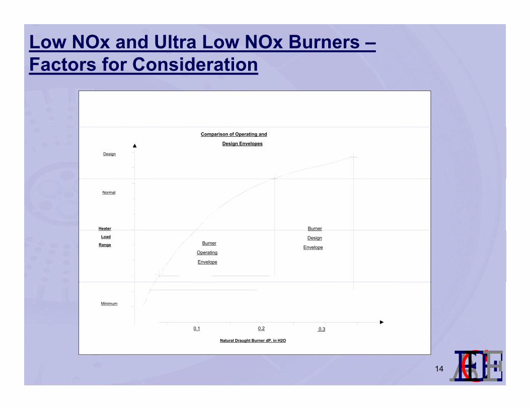
Low NOx and Ultra Low NOx Burners –Factors for Consideration
Comparison of Operating and
Design Envelopes
Design
Heater
Normal
Burner
Burner
Operating
Envelope
Load
RangeDesign
Envelope
Minimum
0.1 0.2 0.3
lmnopqNatural Draught Burner dP. in H2O
14
Low NOx and Ultra Low NOx Burners –Factors for Consideration
Reviewing completely the fuel gas compositions, temperatures
and operating pressures
– Single fuel gas firing
– Requirement to fire high H2 gases to LPG, Butanes, etc...
– Climatic / ambient temperatures and effect on fuel gas conditions.
– Increased tendency for coke formation through variation of fuelsIncreased tendency for coke formation through variation of fuels.
– Possibility of increased maintenance as a result of burner design choice
vs fuel gas composition.
lmnopq15
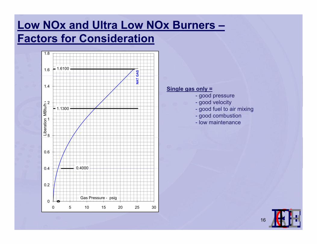
Low NOx and Ultra Low NOx Burners –Factors for Consideration
GAS
1.61001.6
1.8
NAT
G
1.2
1.4
/h
Single gas only = - good pressure- good velocity
1.1300
0.8
1
Libe
ratio
n M
Btu - good fuel to air mixing
- good combustion- low maintenance
0 40000 4
0.6
0.4000
0.2
0.4
Gas Pressure - psig
lmnopq
0000000000000000000000000000000000000000000000000 5 10 15 20 25 30
Gas Pressure psig
16
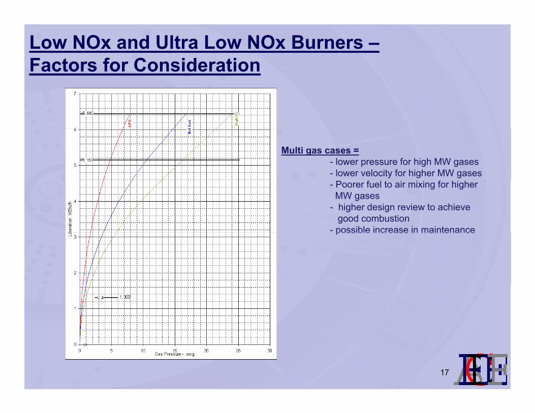
Low NOx and Ultra Low NOx Burners –Factors for Consideration
Multi gas cases = - lower pressure for high MW gases- lower velocity for higher MW gases- Poorer fuel to air mixing for higher MW gases
- higher design review to achieve good combustion
- possible increase in maintenancepossible increase in maintenance
lmnopq17

Low NOx and Ultra Low NOx Burners –Factors for Consideration
Reviewing NOx reduction techniques in terms of staged fuel
vs staged air vs staged combustion
lmnopq18

Staged Air BurnerFlat Flame Burner DynamicsFlat Flame Burner Dynamics
Refractory QuarlRefractory Wall
y
Air Swirler
Secondary
Primary
Combustion AirWindbox
lmnopqGas Gun Fuel Gas
19
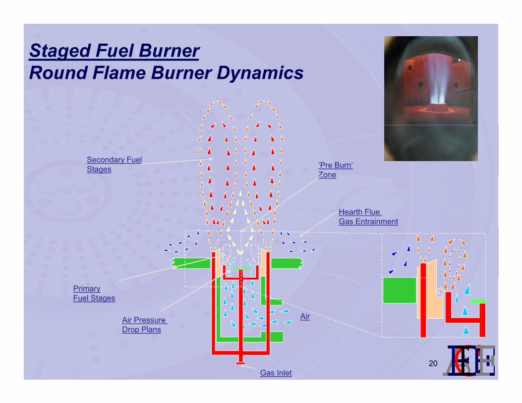
Staged Fuel BurnerRound Flame Burner DynamicsRound Flame Burner Dynamics
Secondary Fuel Stages ‘Pre Burn’
ZoneZone
Hearth Flue Gas Entrainment
Air Pressure Drop Plans
Primary Fuel Stages
Air
lmnopqDrop Plans
Gas Inlet20
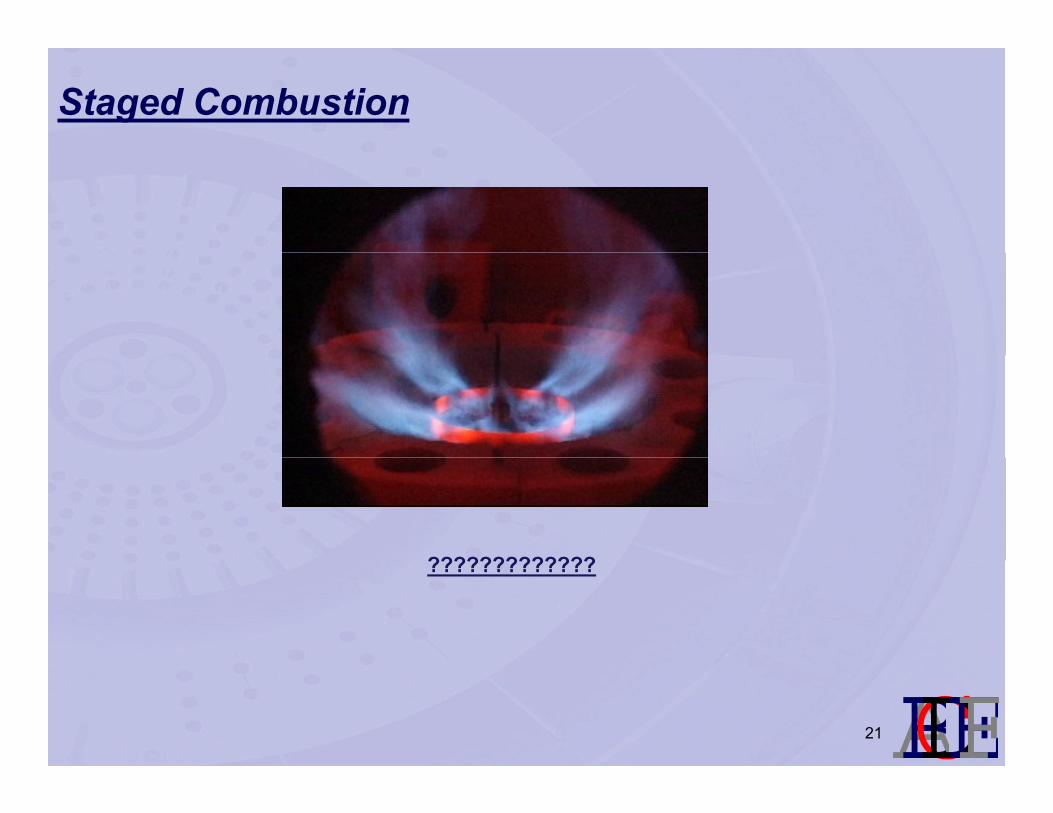
Staged Combustion
??????????????????????????
lmnopq21

Low NOx and Ultra LOw NOx Burners –Advantages Staged Air vs Staged Fuel
St d Ai St d F lStaged Air Staged Fuel
Less Potential for coking Greater NOx reductionWider turndown Easier set up
Less maintenanceIncreased flexibilityIncreased flexibility
Adjustable for changing gas casesTighter flame dimensions
Why????
lmnopq22
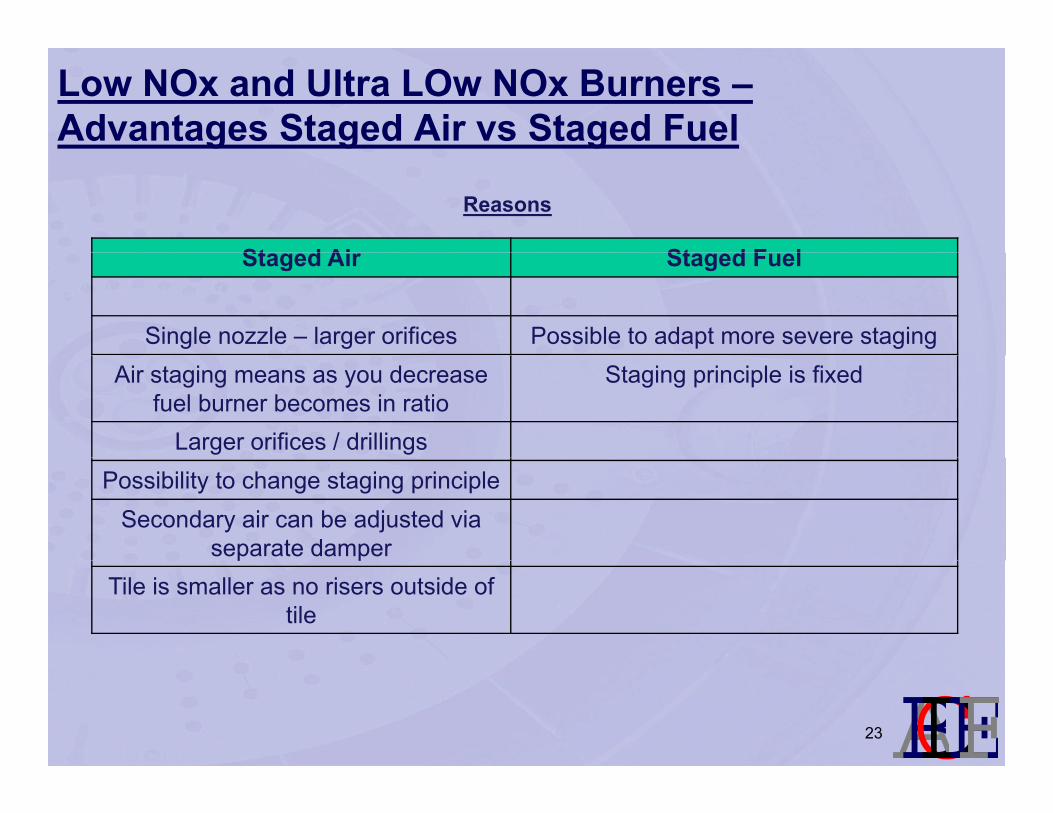
Low NOx and Ultra LOw NOx Burners –Advantages Staged Air vs Staged Fuel
St d Ai St d F l
Reasons
Staged Air Staged Fuel
Single nozzle – larger orifices Possible to adapt more severe stagingAir staging means as you decrease
fuel burner becomes in ratioStaging principle is fixed
Larger orifices / drillingsPossibility to change staging principle
Secondary air can be adjusted via separate damperp p
Tile is smaller as no risers outside of tile
lmnopq23
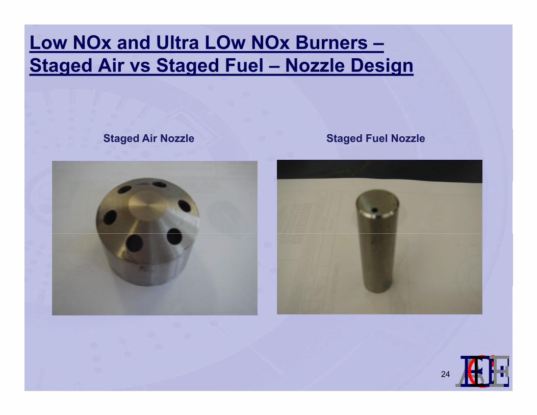
Low NOx and Ultra LOw NOx Burners –Staged Air vs Staged Fuel – Nozzle Design
Staged Air Nozzle Staged Fuel Nozzle
lmnopq24
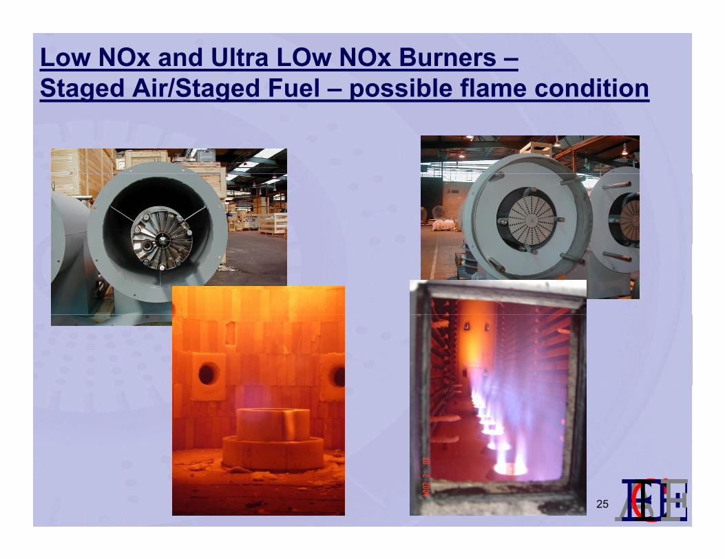
Low NOx and Ultra LOw NOx Burners –Staged Air/Staged Fuel – possible flame condition
lmnopq25
Low NOx and Ultra Low NOx Burners –Factors for Consideration
The need for closer integration of end user, EPC, heater
contractor and burner vendor
The need for open honesty about what can and can not be
achieved in order to avoid long term maintenance and
operational issuesoperational issues.
lmnopq26

Delayed Coking – Burner Design ConsiderationsFuture Requirements.....
Burners predominantly firing gas
Low excess air levels – 5 to 10% (oil 20%)Low excess air levels – 5 to 10% (oil 20%)
CO emissions of < 15 to 20 vppm
Nox emissions of < 20 vppm for gas firing (150 vppm oil firing)
UHC guarantees < 10 ppm
Noise levels < 80-85 dB ‘A’
Turndown limits of 5:1
Ability to meet emissions across all operating conditions
Higher and more even heat flux (tighter flame shape)
Possibly larger burners in restricted burner spacing to meet flux profilePossibly larger burners in restricted burner spacing to meet flux profile
but keep capital cost low.
Ultimately, Lower Capital cost, improved reliability, lower
lmnopqmaintenance, lower emissions & higher efficinecy.
27
Delayed Coking – Burner Design ConsiderationsFuture Requirements.....
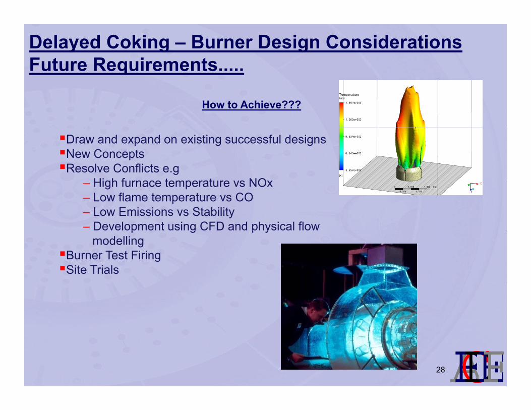
How to Achieve???
Draw and expand on existing successful designsNew ConceptsResolve Conflicts e.g
Hi h f t t NO– High furnace temperature vs NOx– Low flame temperature vs CO– Low Emissions vs Stability – Development using CFD and physical flow p g p y
modellingBurner Test FiringSite Trials
lmnopq28
Delayed Coking – Burner Design ConsiderationsNext Generation Burner Design Evaluation.....
Typical NOx Reduction Technology:
Fuel StagingAir StagingFlue Gas Recirculation (FGR)
Staged fuel or staged air is used to delay combustion, minimise peak flame temperaturepEffect of FGR – adds heat but increases inerts and changes flame temperature / flammability range
lmnopq29
Delayed Coking – Burner Design ConsiderationsAlternative Technology – Staged Combustion.....
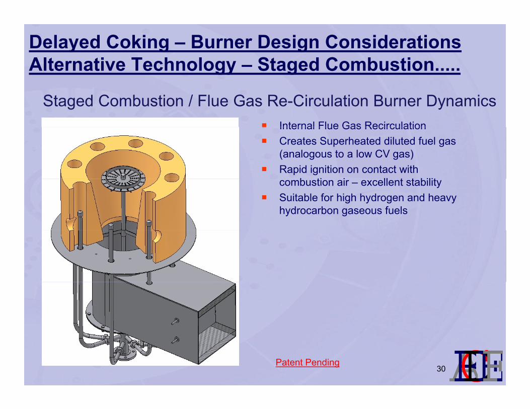
Staged Combustion / Flue Gas Re-Circulation Burner DynamicsInternal Flue Gas RecirculationInternal Flue Gas RecirculationCreates Superheated diluted fuel gas (analogous to a low CV gas)Rapid ignition on contact with
b ti i ll t t bilitcombustion air – excellent stabilitySuitable for high hydrogen and heavy hydrocarbon gaseous fuels
lmnopqPatent Pending30
Advantages of Staged Combustion technology
Simple burner designNo complex low NOx gas nozzlesAvoid pre-mixpStable operation / good burn-outLarge turn-down rangeEven flame profileEven flame profileSuitable for wide range of fuel gas from hydrogen to heavy hydrocarbonsUltra Low NOx (10-15 v ppm??)( pp )Size range 1 – 20 MMBtu/hr
lmnopq31
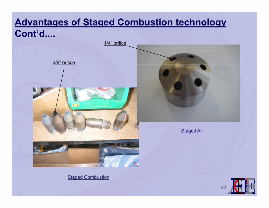
Advantages of Staged Combustion technologyCont’d....
1/4” orifice
3/8” orifice
Staged Air
lmnopqStaged Combustion
32

Advantages of Staged Combustion technologyCont’d....
100% Natural Gas 20% Natural Gas / 80% H2
lmnopq33
Necessities for Meeting End User Future Objectivesj
Review of burner technology vs operating data and conditions.
Increased openness within the industry regarding technology pro’s and con’s.
Larger understanding of end user issues, equipment operability, maintenance requirements. (closer integration)
Clarity in terms of end user emission guarantee requirements –avoid adding safety margin on safety margin
Realisation that a price driven market may not always offer the way forward in terms of achieving optimum furnace operation.
lmnopq34
Questions????
Is Ultra Low NOx the best solution if the operating and maintenance cost of equipment outweigh the cost associatedmaintenance cost of equipment outweigh the cost associated with additional SCR catalyst?
Is it possible moving forward with furnace designs that flameIs it possible moving forward with furnace designs that flame flame burners can be accepted as round flame design?
Are local EPA requirements clearly visible between end user,Are local EPA requirements clearly visible between end user, EPC, heater vendors & equipment suppliers during conceptual design stages of a project?
Do we all know of or have been involved with a furnace where operation could have been improved from an alternative review of burner selection?
lmnopq35