final drainage design report route 8, smithfield/norridgewock
TRANSCRIPT

1 | P a g e
Final Drainage Design Report
Route 8, Smithfield/Norridgewock
For: T. Y. Lin International
and Maine Department of Transportation
By: Northstar Hydro, Inc. June, 2013

Final Drainage Design Report
Route 8, Smithfield/Norridgewock
For: T. Y. Lin International
and Maine Department of Transportation ~\\\\\I II III /// Ill;;.
~'" oF ~,,.., ~'0: By: Vorthf,itar H.l·dro, !Jtc ,~~<c,_ ........... .. .. ... ~.~~; ~ ~ ~...'{~ .. · ... 'l. ~ · .... ' ·· .. 'l. ~"; .. · · .... ~
J une, 2013 ~ / \..E.t4 \ ~ =: ; E.\.: O'c.O\E.t4 : :::: /}... - . \-\i ~I' • :..; % * \~t4\G ~. 1946 ./ \pP \ ~~~;;~#ft ~ u (
1 I
l~

2 | P a g e
1.0 Introduction
This report summarizes final drainage design for the Route 8 project in Smithfield and Norridgewock, Maine. This project comprises approximately 7.8 miles of reconstructed roadway. Approximately 3.9 miles of the reconstruction are in the watershed of North Pond in Smithfield. This lake is classified as a “Lake Most at Risk”, (LMAR). The remainder of the project is not within the watershed of an LMAR or an Urban Impaired Stream (UIS). The following air photo shows the lake drainage basins that influence the project.
2.0 Hydrology Of culverts being replaced, culvert crossing drainage basins range in size from approximately 1 acre to over 100 acres. Several large crossings are not being replaced. The lake watersheds are 22 square miles and 6.6 square miles for North Pond and East Pond. Land used is mixed residential, meadow, woods, and small areas of pavement. Flows were computed using the

3 | P a g e
USGS regional formula for calculation of peak flows, the Rational Method and Hydrocad. Drainage basins and flow calculations were reviewed and revised as part of final design. Hydrology detail is included in the appendix, and Table 1 below summarizes hydrologic data. Table 1, Hydrology Summary, Route 8, Smithfield/Norridgewock.
D.A. TC, min. Q50, cfs
Q100, cfs Q100, cfs
Station Acres USGS Rational USGS Rational 1+36.96 9.1 5 12.5 10.1 15.6 11.3 11+85 4.2 5 6.8 5.5 8.6 6.2 15+54.92 5.8 6.4 8.8 11.4 11.0 12.8 19+41.69 1.5 5 3 3.1 3.8 3.5 26+39.80 1.3 5 2.7 3.4 3.5 3.8 75+50.34 3.06 5 5.3 7.3 6.7 8.1 85+48.55 28.4 10.7 30.2 45.8 37.4 51.3 94+71.41 142.3 25.4 87 88 106 99 120+51.19 41 6.9 31 51 38 57 129+55.61 41 15 41 67 51 75 152+66.17 119.5 52. 44 61 54 68 161+80.63 5.6 10 8.5 10.0 10.7 11. 180+30.00 26 30 28.3 15 35 17 190+11.86 32.5 14 34 41 42 46 201+50 4 5 6.6 7.9 8.3 8.8 223+74.9 66 13 58.6 78 71.8 87 233+26.16 98.7 23 80 72 98 81 239+56.55 2.9 5 5.1 6.5 6.5 7.3 249+10.32 33.5 25 34.4 30 42.3 34 262+24.51 10.3 5 13.7 14.7 17 16.4 266+08 10.2 5 13.6 13 17. 14.3 274+37.59 9.1 5 13 15 16 16.4 284+13.89 34.7 23 35.4 23.7 44 27 305+69.38 13.6 5.9 17.0 25.9 21.2 29 312+91.53 129. 13.2 88 167 108 187 384+00 684.8 317
380

4 | P a g e
Cross culverts, and drainage basins are shown in the map following for project stations 0+00 to 32+00 and are shown below. The national hydrography data-set is also overlaid on the figure. Cross culverts are located in bright green, drainage areas are shown in red.

5 | P a g e
The following map illustrates cross pipes and general drainage for project stations 32+00 to 68+00. For this segment of the project, drainage does not cross the road, and is controlled by either ditches or curbing/closed drainage.

6 | P a g e
The following map shows the project segment from approximate station 65+00 to 129+00. A large culvert/bridge conveys the East Pond outlet stream under the project near project station 68+50. This bridge is not being replaced as part of this project. The project is gently rolling from this bridge to station 129+00. Culverts in this segment were designed based on calculated hydrology and on MDOT experience with this segment of road and lack of flooding issues, giving consideration to existing culvert sizing as well as calculated. Note that Sucker Brook crosses near 135+50. The culverts at this stream crossing were recently replaced so are not being replaced as part of this project.

7 | P a g e
This map shows the project segment from 120+00 to 150+00. This starts a long, flat section of the project where the USGS map shows many potential crossings of intermittent streams. In the field, these crossings have been adjusted to culverts and ditches have been added and used to route flows to selected locations depending on topography and land use. This is an extremely flat section of roadway with slight gradient towards the south and the large stream crossing of Sucker Brook at 135+55. This wide sandy valley bottom mitigates peak runoff to some extent due to infiltration. A new crossing and ditch was added recently near 152+66 to convey flow towards Sucker Brook to the west instead of along the road. Storm runoff can either flow across the road at this culvert or continue in the ditch on the East side of the road. Grading of the ditch will allow flow in either direction. Provision of adequate drainage and culvert cover in this long flat stretch required multiple design iterations.

8 | P a g e
The following map shows the project segment from 200+00 to 249+50. Numerous culverts cross this section of the project where terrain is steeper.

9 | P a g e
The following map shows drainage basins from 262+25 to 306+00. Drainage is fairly steep and flows primarily to the west. 306+00 crosses from west to east.
10 | P a g e
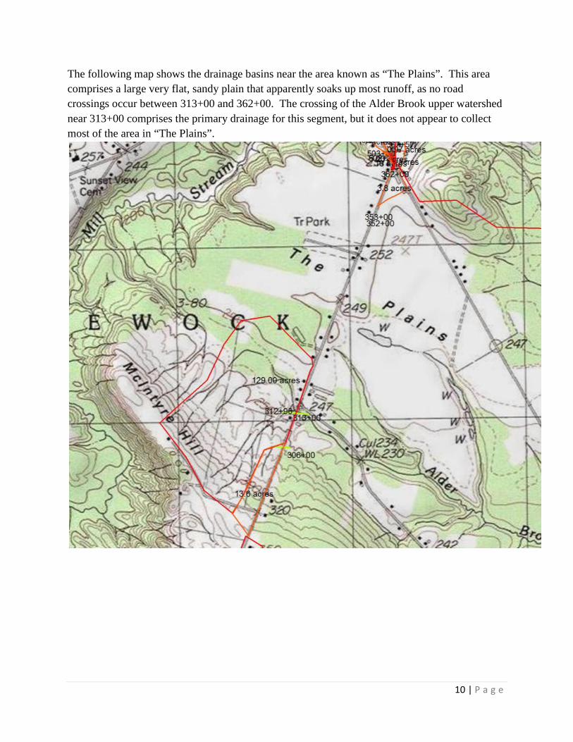
The following map shows the drainage basins near the area known as “The Plains”. This area comprises a large very flat, sandy plain that apparently soaks up most runoff, as no road crossings occur between 313+00 and 362+00. The crossing of the Alder Brook upper watershed near 313+00 comprises the primary drainage for this segment, but it does not appear to collect most of the area in “The Plains”.

11 | P a g e
The map below shows general drainage patterns and drainage basins for the closed drainage systems on Perkins Street and Mechanics Street. Flow is generally towards Mill Stream which flows from Northeast to southwest. The large crossing of Mill Stream at Perkins Street is not being replaced.

12 | P a g e
The following three impaes provide a closer look at drainage basins in the closed drainage portion of the project on Perkins and Mechanics Streets.

13 | P a g e

14 | P a g e
This graphic shows the drainage basin that feeds the culvert at 384+00. Although this culvert is not slated for replacement, rehabilitation of the headwall is included in project plans. Drainage area is in yellow, wetlands in blue. Drainage area is 684.8 acres with 1.8% wetlands.

15 | P a g e
3.0 Culverts Detailed culvert calculations are included in the appendix, including HY-8 calculations. FHWA HEC 5 was also used to check culvert sizing. Existing and proposed culvert information is summarized in the table 2 at the start of the appendix. Culverts at 135+50 and 384+00 are not being replaced.

16 | P a g e
4.0 Driveway Culverts A detailed list of sizes for driveway culverts is included in the appendix. These culverts are sized for an approximate 50-year storm. Each driveway was evaluated for drainage area, and 50-year storm flow for an approximate 50-year storm was calculated for each location, using Table 3 below: Table 3. Driveway Culvert Sizing Chart
Flow estimates
Size Estimates
USGS
Rational
smooth cmp DA acres Q10 Q50 10 50 size size
1 1.1 2.3 1.250 1.3 2 4 5 1.25 1.3 3 5 7 1.25 1.5 5 4.1 7.8 1.250 1.5 6 7 11 1.5 1.5
10 7.3 14 1.5 1.75 20 13 24 2 2 30 17 31 2-2.5 2.5 40 22 40 2.5 2.5 50 26 47 2.5-3 3 70 34 62 3 3 85 39 70 3 3.5
100 46 101 3.5 3.5 150 62 109 3.5 4 200 79 138 4 4 250 95 200
5.0 Ditches Ditches shown on preliminary plans were checked to assure that highest flow level would be below edge of pavement for the 10-year flow within triangular cross sections. It is assumed that ditches will have 4:1 and 2:1 side slopes, and will be 1’ depth below subgrade. The following table shows ditches with highest expected flows, and the expected 10-year maximum depth within the triangular ditch. Detailed ditch calculations were included with the preliminary drainage report.
17 | P a g e
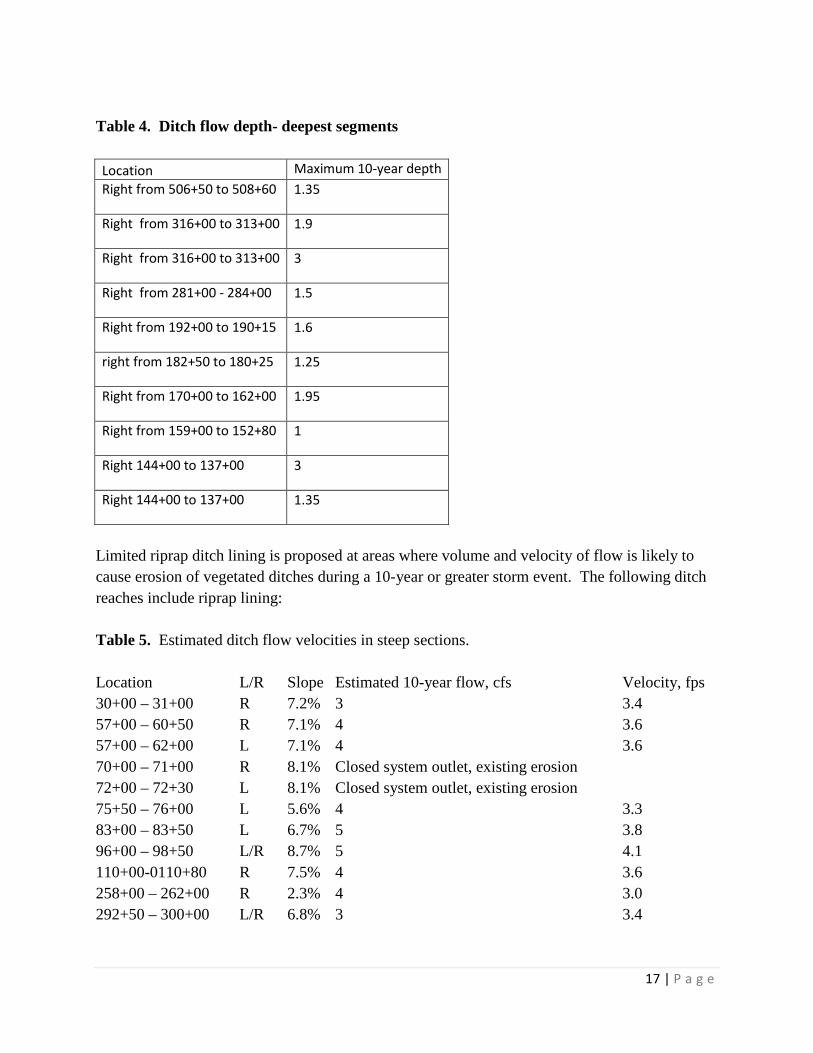
Table 4. Ditch flow depth- deepest segments Location Maximum 10-year depth Right from 506+50 to 508+60 1.35
Right from 316+00 to 313+00 1.9
Right from 316+00 to 313+00 3
Right from 281+00 - 284+00 1.5
Right from 192+00 to 190+15 1.6
right from 182+50 to 180+25 1.25
Right from 170+00 to 162+00 1.95
Right from 159+00 to 152+80 1
Right 144+00 to 137+00 3
Right 144+00 to 137+00 1.35
Limited riprap ditch lining is proposed at areas where volume and velocity of flow is likely to cause erosion of vegetated ditches during a 10-year or greater storm event. The following ditch reaches include riprap lining: Table 5. Estimated ditch flow velocities in steep sections. Location L/R Slope Estimated 10-year flow, cfs Velocity, fps 30+00 – 31+00 R 7.2% 3 3.4 57+00 – 60+50 R 7.1% 4 3.6 57+00 – 62+00 L 7.1% 4 3.6 70+00 – 71+00 R 8.1% Closed system outlet, existing erosion 72+00 – 72+30 L 8.1% Closed system outlet, existing erosion 75+50 – 76+00 L 5.6% 4 3.3 83+00 – 83+50 L 6.7% 5 3.8 96+00 – 98+50 L/R 8.7% 5 4.1 110+00-0110+80 R 7.5% 4 3.6 258+00 – 262+00 R 2.3% 4 3.0 292+50 – 300+00 L/R 6.8% 3 3.4

18 | P a g e
Table 6 below includes typical calculations for triangular ditch flow, for slopes from 5-9%, with riprap lining and Q10 from 3-5 cfs. Many grasses are erodible at 4 fps according to the AASHTO Model Drainage Manual, 1991. The table is included in the appendix under the section relating to BMP design. Table 6. Velocity Calculations.
Q10 h, ft n S S^1/2 Side slopes side slopes 1.49/n*s^1/2 A P A/P^2/3 Q, calc V, fps
5 0.65 0.04 0.06 0.24 4.00 2.00 9.12 1.27 4.13 0.45 5.26 4.15
5 0.63 0.04 0.07 0.26 4.00 2.00 9.86 1.19 4.01 0.45 5.22 4.39
5 0.6 0.04 0.08 0.28 4.00 2.00 10.54 1.08 3.82 0.43 4.90 4.54
5 0.6 0.04 0.09 0.30 4.00 2.00 11.18 1.08 3.82 0.43 5.20 4.82
4 0.6 0.04 0.06 0.24 4.00 2.00 9.12 1.08 3.82 0.43 4.25 3.93
4 0.6 0.04 0.07 0.26 4.00 2.00 9.86 1.08 3.82 0.43 4.59 4.25
4 0.55 0.04 0.08 0.28 4.00 2.00 10.54 0.91 3.50 0.41 3.89 4.28
4 0.55 0.04 0.09 0.30 4.00 2.00 11.18 0.91 3.50 0.41 4.12 4.54
3 0.55 0.04 0.06 0.24 4.00 2.00 9.12 0.91 3.50 0.41 3.37 3.71
3 0.55 0.04 0.07 0.26 4.00 2.00 9.86 0.91 3.50 0.41 3.64 4.01
3 0.5 0.04 0.08 0.28 4.00 2.00 10.54 0.75 3.18 0.38 3.02 4.02
3 0.5 0.04 0.09 0.30 4.00 2.00 11.18 0.75 3.18 0.38 3.20 4.26
6.0 Stormwater Quality MOA review. The Route 8 project in Smithfield/Norridgewock comprises approximately 7.8 miles of reconstructed roadway. Approximately 3.9 miles of the reconstruction are in the watershed of North Pond in Smithfield. This lake is classified as a “Lake Most at Risk”, (LMAR). The remainder of the project is not within the watershed of an LMAR or an Urban Impaired Stream (UIS). The Memorandum of Agreement (MOA) between MDOT and MDEP applies to this project since it is a linear project.

19 | P a g e
This MOA stipulates the following for this project: 1. “Basic” Standards apply to this project. These standards are generally met by applying MDOT’s BMP manual. This includes stormwater measures such as inlet/outlet protection for culverts, properly constructed ditches, etc. These standards include basic
• Erosion and Sedimentation Control • Inspection and Maintenance • Housekeeping
2. The project is in the watershed of an LMAR, North Pond. Under the preliminary design layout, existing shoulders within this watershed totals approximately 5 acres. Approximately 2.6 acres of this existing gravel shoulder area will be paved. This results in no net gain in new impevrious area that drains to this pond. 3. The project is in an existing travel corridor and thus may comply with the General Standards with a redevelopment waiver. The MOA states the Linear Portion of the project within the watershed of an LMAR shall meet the General Standards “to the extent practicable as determined through consultation with and agreement by DEP, except that redevelopment of existing impervious area may qualify for the exception in Section 4(B)(3)(e).” For this project, the net gain in impervious area is less than 20,000 square feet; therefore, the Basic Standards apply. The following figure shows the project and the watershed of North Pond and East Pond.

20 | P a g e
4. The total new pavement for the project is less than 3.0 acres. Because the new pavement is less than 3.0 acres, the project can utilize the General Standards rather than the Phosphorous Standards to meet the Phosphorous Standard. 5. The Flooding Standard applies to the extent practicable, but would only be mandated if new impervious was > 3.0 acres. Meeting the Basic Standards: Ditches were checked for capacity and velocity for selection of lining to resist erosion. Critical segments are noted above in section 5.0 on ditch calculations. Three riprap downspouts are proposed at 42+90 L, 48+50 L and 68+50 R. These structures assist in avoiding concentrated flow, with riprap attenuating flow velocity. Each downspout will include a plunge pool or apron at the base to dissipate energy before outfall.

21 | P a g e
All culverts will include inlet and outlet protection. Standard sized outlet protection is proposed for most culverts. Outlet protection was checked with design calculations for the following larger culverts:
94+71 223+75 233+26 Calculations are included in the appendix. The following locations were identified for further investigation: Station 68+50, L/R: 68+00 R - existing, 69+00 L new, 71+00 L existing Station 313+50 L: Outlet replaces ditch/drive culvert, short length of closed drainage added Station 380+70 Left: New outlet Station 384+15 Left: New outlet Station 515+50 Right: New outlet The following paragraph is excerpted from DEP Chapter 305, 11. State Transportation Facilities, B. Standards. (21) A vegetated area at least 25 feet wide must be established and maintained between any new stormwater outfall structure and the high water line of any open water body. A velocity reducing structure must be constructed at the outlet of the stormwater outfall that will create sheet flow of stormwater, and prevent erosion of soil within the vegetated buffer. If the 25 foot vegetated buffer is not practicable, the applicant must explain the reason for a lesser setback in writing. Approval from the DEP must be in writing and recommendations must be incorporated into the activity.
68+50 L/R
This location has three outfalls, only one that is “new”.
68+40 R: This outlet is an existing stormwater outfall. A new outfall is to be constructed. This picture is looking at bank at 68+40 R. Note steep bank and existing outlet in center of picture. A riprap downspout with lip is proposed at this location. The steep bank and roadway behind the bank preclude setting the outfall back further and there is no room for a level spreader. Q10 is 5.8 cfs and Q50 is 7.8 cfs. A riprap downspout will be used at this location.

22 | P a g e
The following is a close up photo of bank with the existing outlet in the center of the photo.
This photo shows a close up at the bank at the existing outlet at left bottom of photo.

23 | P a g e
At 68+40 L there is no existing stormwater outlet, but there could possibly be room to put a level spreader to handle flow from 68+40 R, but this would become a “new” outfall, and is in a yard as shown below. This location was not recommended.
One catch basin outlets to 69+00 left. Although there is quite a bit of space to include a level spreader with setback, grades from catch basin outlet to the stream do not allow the spreader to

24 | P a g e
be put at grade level. It is proposed to install a wide ditch base at this location. With a Q10 of approximately 1 cfs, the level spreader/ditch base would be 4’ wide. This is a “new” outlet
The last outlet to this stream currently exits the storm drainage system 71+00 R. This outfall turns toward the stream near 70+50 R as shown on the following photo.
This photo shows the same location, looking south, with flow towards the left in picture from approximately 71+00 R. The new outfall will be close to 71+20 R. Q10 is calculated to be 5.9

25 | P a g e
cfs and Q50 is 7.6 cfs. The preliminary design utilized a ditch to the stream bank, which would assist in draining the subgrade as well as conveying stormwater. Another option is to construct a very flat ditch section for approximately 24’, the length of a level spreader, such that stormwater can flow left from the ditch as it does now, but with a constructed level spreader outlet. The final design includes a shallow ditch from 68+70 R to 70+00 R that will not entirely drain the subgrade. A ditch turnout with a level spreader will be used at 70+00 R to maintain current flow conditions.
95+50: The following photos show the existing outlet at 95+50 R. The proposed plunge pool and replacement culvert will improve this currently “hanging culvert. This stream has not been flagged as a “fish” stream.

26 | P a g e
This is the existing scour hole below that culvert, with the culvert outlet near the center of the photo.
313+50 L: An existing ditch/driveway culvert outlet near 313+50 L outlets to a stream that crosses near 313+00 from L to R. This stream was identified as a “fish” stream. The existing outlet will be maintained, but a portion of drainage from this system will be relocated to a new

27 | P a g e
outlet that will include approximately 300’ of new curbing and a ditched area of approximately 3800’. This area drains a very very flat area underlain by sand and gravel. Surface runoff will be limited by the grade and by the permeable soils. An estimated 5.2 acres drain to this location, with a calculated Q10 of 6 cfs. A level spreader at this location would be approximately 24’ long. Due to grading constraints, this structure will not fit the site, so outlet protection suitable for fish passage will be used at this location.
380+70 L: The following photo shows the proposed location of the new outlet near 380+70 L. The setback from the river will be more than 25’. A level spreader will be constructed at the outlet from the pipe. Q 10 is 2.8 cfs, so spreader width would be approximately 11’.
384+20 L:

28 | P a g e
One new outlet is proposed near 384+20 L. This location will drain only two catch basins, so flow is minimal, with Q 10 calculated to be less than 0.9 cfs. A level spreader would be about 4’ wide. The only options at this location for construction of a flow dissipation structure would be to use part of the parking area or to locate the outlet near 383+50 L. Due to site constraints, and limited amount of flow, it is proposed to use a simple riprap apron at the pipe outlet. This shows the steep bank downstream near 384+20 L.
This photo shows the grassy area near 383+50 L, but grading in a level spreader at this location would be difficult. .

29 | P a g e
516+50 R: A new stormwater outlet is proposed near 516+50 R. Q10 at this location is estimated to be 11.1 cfs, requiring a level spreader of about 40’ length. DEP guidance suggests 25’ as a maximum length, and will be used. The site has space for this type of structure, with required setback.
This photo also shows 515+50 R taken from the road.

30 | P a g e
513+50 R: There is also an existing stormwater outlet near 513+50 R, which will be replaced. The bank does not provide space or setback for a level spreader. This photo shows the outlet location. Q10 is 3.2 cfs

31 | P a g e
7.0 Fish Streams
Maine DOT assisted in identifying streams for which fish passage was required when designing culverts. Maine DOT also assisted with the design by identifying bankfull width and recommended culvert sizing. The two culverts for which fish passage accommodations were made are located at project stations 223+75 and 312+92. Both culverts will be 5’ in diameter and will be embedded to accommodate passage. Detailed calculations are included in the appendix.
8.0 Closed Drainage Systems
Closed drainage systems were designed in accordance with Maine DOT Highway Design Guide, Chapter 12. Closed system details are included on project plans and in the appendix.

32 | P a g e
References: 1. U. S. Dept. of the Interior, Geological Survey, with Maine Dept. of Transportation. Estimating the Magnitude and Frequency of Peak Flows for Streams in Maine for Selected Recurrence Intervals. Water Resources Investigations Report 99-4008. 2. Maine Dept of Transportation. Best Management Practices for Erosion and Sediment Control. 3. Maine Dept. of Transportation. Urban and Arterial Highway Design Guide. Chapter 12, May 2002 4. U.S. Dept of Transportation, FHWA. Hydraulic Design of Highway Culverts. Hydraulic Design Series 5. September, 1985. 5. U.S. Dept of Transportation, FHWA HY-8. Culvert Design Software. Version 7.2, January, 2012

33 | P a g e
Appendix
Tables 1a and 1b: Hydrologic Calculations A-1a, 1b Table 2. Summary of Culvert Calculations A-1 Culvert Calculations A-2 – A-189 Driveway Culvert Calculations A-190, 191 BMP Calculations A-192-A-199 Hydraflow/Closed System Calculations A-200-285

Environmental Office Maine Dept. of Transportation Hydrology Unit
Smithfield Norridgewock EOB
12776.00 rev june 2013
Smithfield Norridgewock Norridgewock
--~~----ra6re-1'a--:-Rycrrorogy-car cu rations us-Gs~~- - ------------~------ ---------~·----------~ · ~-~--~-----~-------~~~---~----------------------- --~----- -- --~~---~---~------------~-- ------- -- -
I US Ius or metric
------ -- -------
Station Area NWI Q2 Os Q10 Q25 Oso Q100 Remarks Wetland
ac % ft3/s ft3/s ft3/s ft3/s ft3/s ft3/s I 0 I 0.0 i
I I I I I I
384+00 684.80001 1.8 80.651 141.021 189.504 259.471 317.383 380.815 1312+91.53 129.0000 1.5 19.941 36.60i 50.3841 70.911 88.248 107.532 1305+69.38 13.6203! 0.0 3.25! 6.401 9.127! 13.371 17.0651 21.263 1284+13.89 34.66481 0.0 7.171 13.76i 19.3781 27.97[ 35.364 43.695 1274+37.59 9.1000! 0.0 2.311 4.60! 6.594! 9.72[ 12.459 15.581 1266+08 10.20001 0.0 2.541 5.051 7.229j 10.641 13.619[ 17.014 262+24.51 10.30001 0.0 2.561 5.091 7.2861 10.72[ 13.7231 17.142 249+10.32 33.5000i 6.97[ 13.38 18.851[ 27.22 34.4331 42.558 239+56.55 2.9000i 0.88 1.80[ 2.623[ 3.94 5.106[ 6.452 [233+26.16 98.70001 0.0 17.42 32.46[ 45.037[ 63.92 79.986! 97.902 1223±7.4.9-- ---- 66.oooo 1 12.381 23.33 32.5621 46.51 58.4371 71.786 !201+50 4.0000! 1.15 2.34[ 3.399 5.08 6.5621 8.267 !190+11.86 32.4600! 6.78[ 13.04[ 18.378[ 26.55 33.597! 41.536 : 180+30 26.0000 5.62! 10.87! 15.3681 22.28 28.257! 35.004 1161+80.63 5.6000 1 1.53i 3.09l 4.4591 6.63 8.532! 10.716 j152+66.17 119.5000: 10.0 11.10: 19.56] 26.334! 36.25 44.4421 53.558 1129+55.61 41.50001 8.36! 15.95: 22.403: 32.24 40.6931 50.198 120+51.19 41.0000! 3.3 6.76! 12.69. 17.663! 25.19 31.609! 38.820
194+71.41 142.3ooo I 2.6 20.26 1 36.87 1 50.540' 70.80 87.850i 106.791 :85+48.55 28.35001 6.05 11.67! 16.478! 23.86 30.2301 37.419 ;75+50.34 3.0601: 0.92 1.88, 2.739: 4.11 5.325: 6.725
~ ~26+39.80 1.3000 0.44 0.931 1.374: 2.09 2.7311 3.476 119+41.69 1.4500 0.49 1.02: 1.5oo: 2.28 2.974 3.781
l -- 15+54.92 5.8000, 1.58 3.18i 4.586 6.81 8.768. 11.010
e :11 +85 4.20001 0.1 1.19' 2.42' 3.5141 5.24' 6.772 8.526 :1+36.96 9.1000 0.0 2.31 4.60 6.594• 9.72 1 12.459 15.581 I I ------ --~ -----
Template USGSEqn3.XL T Page USGS Rev. Date 15 May 2001

~ \
~
Smithfield Norridgewock 12776.00
Prepared by: .:E;.:;O:.:;B:....~,.,..,----Date: rev june 2013
Smithfield Norridgewock ------------------------------------~---------~---- ------- ------ ---- -------- -----~ ------- ----------------. ------~-------------------------~ ------------.
Table 1 b. Hydrologic Calculations Rational Method
(Port-1/East-2/Rang-3/P/-4/Newport-5/Mil-6)
T = 2 yrs T = 10 yrs T =50 yrs T = 100 yrs Station Area c Tc I i2 I Q2 Tc i1o I Q10 Tc I iso Oso Tc i100
I
Q100 I
ac min (in/hr) I (ft3/s) min i (in/hr) ! (ft3/s) (in/hr) I (ft3/s) (in/hr) I (ft3/s) I min I min I I
I I I I I I ! !
384+00 684.80 0.23 20.01 2.0301 323.64 17.7 1 3.113! 496.29 16.21 4.251: 677.70 15.6 4.828: 769.71 312+91.53 129.00r 0.28 13.41 2.5211 89.42 13.3 3.5841 127.15 13.21 4.6781 165.95 13.1 5.233i 185.65 305+69.38 13.621 0.30 6.01 3.586: 14.75 5.9[ 4.947i 20.35 5.9~ 6.3011 25.92 5.8 7.0501 29.00 284+13.89 34.66i 0.19 25.91 1.7441 11.62 24.11 2.6351 17.56 23.0[ 3.560' 23.72 22.6 4.0201 26.78 274+37.59 9.10! 0.25 5.0 1 3.8191 8.69 5.o: 5.2151 11.86 5.01 6.593! 15.00 5.0 7.3681 16.76
266+08 10.201 0.19 5.01 3.819! 7.50 5.0[ 5.2151 10.25 5.01 6.593! 12.95 5.0 7.3681 14.48 262+24.51 10.3 0.215 5.0! 3.8191 8.46 5.01 5.215[ 11.55 5.01 6.593[ 14.60 5.0 7.3681 16.32
249+10.32 33.50[ 0.27 25.01 1.782[ 16.12 25.0 1 2.584[ 23.37 25.01 3.4041 30.79 25.0 3.806[ 34.43 239+56.55 2.901 0.34 5.01 3.8191 3.77 5.0[ 5.215! 5.14 5.0[ 6.593! 6.50 5.0! 7.3681 7.26 233+26.16 98.701 0.21 28.2: 1.6551 34.30 25.61 2.5501 52.85 24.01 3.483! 72.20 23.31 3.9491 81.85 223+74.9 66.001 0.25 13.2[ 2.5441 42.07 13.1! 3.612[ 59.75 13.01 4.711! 77.92 12.9! 5.2701 87.15 201+50 4.001 0.30 5.0[ 3.819! 4.58 5.0! 5.215[ 6.26 5.0J 6.593[ 7.91 5.0 1 7.3681 8.84
190+11.86 32.46[ 0.28 15.61 2.335[ 21.22 14.7[ 3.4171 31.06 14.11 4.536! 41.23 13.9[ 5.106[ 46.41 180+30 26.00l 0.19 33.8[ 1.4781 7.30 31.21 2.2771 11.25 29.5[ 3.1021 15.32 28.9[ 3.513! 17.35
161+80.63 9.001 0.48 5.01 3.8191 16.38 5.0 5.2151 22.36 5.0[ 6.5931 28.27 5.0! 7.3681 31.60 152.+66.17 119.501 0.23 52.0! 1.111! 30.55 52.01 1.664. 45.73 52.01 2.2071 60.66 52.0'1 2.478\ 68.09 129+55.61 41.501 0.37 15.01 2.3811 36.57 15.0! 3.381 i . 51.91 15.0[ 4.410; 67.71 15.0! 4.924! 75.61 120+51.19 41.00! 0.21 7.41 3.309j 28.49 7.1! 4.641[ 39.96 6.9! 5.981 I 51.50 6.9; 6.710[ 57.77 94+71.41 142.30! 0.18 27.5! 1.6801 44.00 26.2 2.514! 65.83 25.41 3.3731 88.33 25.1 i 3.800! 99.49 85+48.55 28.35! 0.32 10.91 2.789[ 24.99 10.8 11 3.938! 35.28 10.71. 5.113, 45.80 10.6 11 5.7211 51.251 75+50.34 3.06 0.36 5.01 3.819! 4.22 5.0! 5.2151 5.76 5.01 6.593; 7.28 5.01 7.3681 8.14 26+39.80 1.30! 0.39 5.6! 3.682! 1.88 5.2 1 5.143! 2.62 5.0! 6.585 3.36 5.0 1 7.3681 3.76 19+41.69 1.45• 0.33 5.0! 3.819! 1.82 5.0; 5.2151 2.48 5.0: 6.5931 3.14 5.0: 7.3681 3.51 15+54.92 5.80' 0.32 6.71 3.4391, 6.40 6.5! 4.7881 8.90 6.41 6.137! 11.41 6.3: 6.877' 12.79
11+85 4.20' 0.20 5.01 3.819[ 3.21 5.0. 5.2151 4.38 5.01 6.593 1 5.54 5.01 7.368 6.19. 1+36.96 9.10 0.17 5.0[ 3.819: 5.83 5.0. 5.215: 7.96 5.0 6.593 10.06 5.0 7.368· 11.25

\
Final Drainage Report, Route 8 Smithfield-Norridgewock
Table 2, Culvert Summary
Hydrology Subgrade -------- -- -----
---- D,A.-- ------ QSO - --- QlOO ----
XS Station Acres Design Design Inlet
312+91.53 129.0 88 108.0 243.55
243.55 -1 -·· - --243.S5
305+69.38 13.6 17.1 21.3 257.13
284+13.89 34.7 35.4 44.0 344.68
double culvert 344.68
double culvert 344.68 274+37.59 9.1 13 17.0 362.20
266+08 10.2 13 14.3 360.08
262+24.51 10.25 14.7 16.4 349.37 249+10.32 33.5 34.4 42.3 328.80
double 24" 17 21.0 328.80
239+56.55 2.9 5 6.5 305.55 233+26.16 98.7 80 98.0 294.14
223+74.90 66 58.6 71.8 291.79 223+74.90
201+50 4 7.9 8.8 190+11.86 32.5 33.6 42.0 300.88
180+30.00 26 28.3 35.0 293.00
161+80.63 5.6 10 11.0 275.49
152+66.17 119.5 44 54.0 275.07 129+55.61 41 41 51.0 273.75 120+51.19 41 31 38.0 284.17
94+71.41 142.3 87 106.0 285.87
85+48.55 28.4 30.2 37.4 286.06
75+50.34 2.9 7.3 8.1 281.52 26+39.80 1.3 3.5 3.8 333.10 19+41.69 1.45 3.2 3.5 335.46
15+54.92 5.82 11.4 12.8 349.88
11+85 4.2 5.5 6.2 359.00
1+36.96 9.1 10.1 11.3 360.74
-,....,
Inverts Existing Final Q50* HW/D QlOO head HW/D top of pipe Notes ·lnlet----0utlet--- Gulveft---size --- 8eadwater_ _______ tJYlL __ Q1_9_Q ________
------------------------ -·- HY8 Elev - - - -
-- -- - ----------- ------ - - - --- - - --Size ft
238.24 237.98 3.0 5 243.35 244.80 241.24 FISH stream -cmp 2' embed
238.24 237.98 5 242.70 243.60 241.74 cmp 1.5' embed -- 238.24- 237.98 --- .. --I - _5 - - 242.90- 244.10 241.24 smooth 2' embed
254.31 253.36 1.5 2 256.81 1.3 257.41 1.6 256.31
342.28 341.67 1.5 3 345.28 1.0 345.78 1.2 345.28 Use 1- 2' based on existing/no issues
342.28 341.67 2 344.88 2.8 345.48 1.6 344.28
342.28 341.67 1.5 347.18 3.3 347.28 3.3 343.78
358.75 357.28 1.5-2 2 360.70 1.0 361.05 1.3 360.75
356.69 356.20 1.3 2 358.79 1.1 359.19 1.3 358.69
346.43 346.08 1.5 2 348.69 1.1 348.81 1.3 348.43
326.34 326.14 2.0
326.34 326.14 2.0 2 328.84 1.3 329.5 1.6 328.34 existing 24", no issues, replace in kind
303.14 302.65 1.5 1.5 304.64 1.0 304.84 1.1 304.64
288.90 287.98 4.0 4 292.90 1.0 293.60 1.2 292.90
286.34 285.82 3.0 3.5 290.24 1.1 290.94 1.3 289.84 FISH Stream, use 60"
5 289.80 290.30 embed 1.5-2'
1.5 1.2
296.59 295.74 2.5 2.5 300.09 1.4 301.09 1.8 299.09
290.55 290.31 2.5 293.55 1.2 294.25 1.5 293.05 existing 15" no issues, use 18"
273.03 272.78 1.5 1.5 275.33 1.5 275.63 1.7 274.53
271.54 270.37 3 275.04 1.2 279.37 1.4 274.54
270.76 269.90 1.5 3 274.06 1.1 274.86 1.4 273.76 no recorded issues, reduce to 24"
281.31 280.53 1.5 2.50 284.51 1.3 285.31 1.6 283.81 wetland storage, reduce to 24"
276.45 273.41 2.5 4 280.78 1.1 281.55 1.3 280.45
281.29 277.86 2.0 2.5 284.39 1.2 285.19 1.6 283.79
278.98 276.59 1.5 1.5 280.65 1.1 280.78 1.1 280.48
330.97 330.53 1.5 1.5 332.45 1.0 332.58 1.2 332.47
331.90 330.53 1.5 1.5 332.87 0.7 332.92 0.7 333.40
346.75 344.77 1.25 1.5 349.35 1.8 349.75 2.0 348.25
357.00 355.20 1.5 358.40 0.9 360.50 1.0 358.50
357.71 357.16 1.5 1.5 360.01 1.5 360.31 1.7 359.21 - -

Water Surface Profile Plot for Culvert: 1+35 ""DA-:: 9. 1-Au..uo .
Crossing- Smith11eld RouteS~ Design Discharge- 10.1 ~fs Culvert- 1.,..35, Culvert Discharge- lCU d's
363-
1-
362-
:;:;-- 361 -~
c 0
i5 360-> (J)
w 359-
1-
1-
1-
+----------------
~-·· 1- ............. ._ ··· ...• ········- ·····-- ·······-- ·····--- ·····--· ... ····-····· --------------'--){
358-
1-
357 -J I .l;l~yo.wmr,.,...,
-10 ~1f21UU~vwi£!1d'f*i.•&mubm •• ~il!iQ0JJijii2 .:lmr~mMJ&"'*SMillirk 0 10 20
Culvert Data Summary - 1 +35
Barrel Shape: Circular
Barrel Diameter: 1.50 ft
Barrel Material: Concrete
Embedment: 0.00 in
Barrel Manning's n: 0.0120
Inlet Type: Conventional
Station (ft)
Inlet Edge Condition: Square Edge with Headwall
Inlet Depression: NONE
30 40 50
A--~
q It I

Culvert Performance Curve Plot: 1 +35
360.3
-~ 3602 _,__. ~· c 360.1 0
~ 360.0 (!)
':: 359.9 Q)
~ 359_8 -o (iJ
:!E. 359_7
359.6
Perfon11ance Curve Culvert 1 _;_35
II] [I] Inlet Control Elev Outlet Control Elev
3 59-5 I dwal~"'-~-bz:dmh:2ijmtm!mwlm:kmqmLmbsb.arlm,f"",bwb ·• I. I I I J I J. f' wU I .. I I I I . 1m~--*~ 8.0 8.5 9.0 9.5 10.0 1 0.5 11.0
Total Discharge (cfs)
ft--

0 A-/ Cf. I I) Gcu:J .
Table 1 - Summary of Culvert Flows at Crossing: Smithfield Route 8 Headwater Elevation Total Discharge (cfs) 1 +35 Discharge (cfs) Roadway Discharge ltera ions
(ft) (cfs)
359.53 8.00 8.00 0.00
359.59 8.33 8.33 0.00
359.66 8.66 8.66 0.00
359.73 8.99 8.99 0.00
359.81 9.32 9.32 0.00
359.89 9.65 9.65 0.00
359.97 9.98 9.98 0.00 360.00 <.1 o.-ill}.Q.S() 10.10 0.00 360.13 10.64 10.64 0.00 1
360.22 10.97 10.97 0.00 1
360.32 ( 11.3d)JQ IOU 11.30 0.00 1
363.00 18':"27 18.27 0.00 Overtc pping ()"' --7
r!Jub rq k.::::-1.3~ o. 7 v
A 1

Rating Curve Plot for Crossing: Smithfield Route 8
360.3
360.2 ...... ':':::- ?60 1 c J .
0
~ 360.0 G.)
w '- 359.9 G.) ...... m ~ 359.8 m G.)
I 359]
359.6
Total Rating Curve Crossing: Smithfield Route 8
'="'t)9 5'¥1z:drmhk 1 1 ::dmrJ.~JmJa,;! I I .I I I ;r -~ I 1 alwqmlmwtL~ .._"').._ - ,, n~-, '=~r :::k11f!lli • 8.0 8.5 9.0 9.5 10.0 10.5 11.0
Total Discharge (cfs)
A--

Table 2- Culvert Summary Table: 1+35 Total Culvert Headwater Inlet Control Outlet Flow Normal Critical Outlet Depth Tailwater Outlet Tailwater
Discharge Discharge Elevation (ft) Depth (ft) Control Type Depth (ft) Depth (ft) (ft) Depth (ft) Velocity Velocity (cfs) (cfs) Depth (ft) (ft/s) (fils)
8.00 8.00 359.53 1.816 o.o· 5-S2n 0.836 1.092 0.837 1.010 7.894 1.313
8.33 8.33 359.59 1.883 o.o· 5-S2n 0.857 1.113 0.858 1.031 7.970 1.327
8.66 8.66 359.66 1.952 o.o• 5-S2n 0.879 1.135 0.880 1.050 8.040 1.341
8.99 8.99 359.73 2.023 o.o· 5-S2n 0.900 1.156 0.901 1.069 8.108 1.354 I
9.32 9.32 359.81 2.098 o.o· 5-S2n 0.923 1.178 0.923 1.088 8.167 1.367
9.65 9.65 359.89 2.175 o.o· 5-S2n 0.945 1.199 0.945 1.107 8.216 1.380 '
9.98 9.98 359.97 2.255 o.o· 5-S2n 0.968 1.214 0.969 1.125 8.275 1.392 I
QSO 10.10 10.10 360.00 2.285 o.o· 5-S2n 0.976 1.220 0.979 1.131 8.282 1.397
10.64 10.64 360.13 2.425 o.o· 5-S2n 1.012 1.244 1.013 1.160 8.386 1.416
10.97 10.97 360.22 2.514 o.o· 5-S2n 1.035 1.259 1.068 1.177 8.147 1.427 I
Q/00 11.30 11.30 360.32 2.607 o.o· 5-S2n 1.058 1.274 1.088 1.194 8.216 1.439
6 .;htpa ck $(J;O./,
A- (p

********************************************************************************
Inlet Elevation (invert): 357.71 ft, Outlet Elevation (invert): 357.16 ft
Culvert Length: 40.00 ft, Culvert Slope: 0.0137
********************************************************************************
fh'7

Rating Curve Plot for Crossing: 11+85
358.45
g 358_40 c 0 ....., ~ 358.35 ill
w '--
2 358.30 ill $ -o ill ~ 358.25
358.20
Total Rating Curve Crossing: 11-'-85
4_5 5.0 5.5 Total Discharge (cfs)
6_0
{}~?

~ Tabl mmary Table: Culvert 1 q1vt\ lZ... Total Culvert Headwater Inlet Control Outlet Flow Normal Critical Outlet Depth Tailwater Outlet Tailwater
Discharge Discharge Elevation (fl) Depth (ft) Control Type Depth (ft) Depth (ft) (ft) Depth (ft) Velocity Velocity (cfs) (cfs) Depth (ft) (ft/s) (ft/s)
4.40 4.40 358.17 1.175 o.o· 1-S2n 0.458 0.802 0.461 0.392 9.573 <:.962
4.58 4.58 358.20 1.205 o.o· 1-S2n 0.467 0.818 0.467 0.402 9.777 2.999
4.76 4.76 358.23 1.234 o.o· 1-S2n 0.476 0.835 0.478 0.410 9.865 3.037
4.94 4.94 358.26 1.264 o.o· 1-S2n 0.485 0.852 0.491 0.419 9.898 3.073
5.12 5.12 358.29 1.294 o.o· 1-S2n 0.493 0.869 0.500 0.427 10.028 3.108
5.30 5.30 358.32 1.323 o.o• 1-S2n 0.502 0.886 0.508 0.436 10.034 3.140
5.48 5.48 358.35 1.353 o.o· 1-S2n 0.511 0.902 0.517 0.444 10.122 3.174
G!iP- 5.50 5.50 358.36 1.356) o.o· 1-S2n 0.512 0.904 0.518 0.445 10.133 3.178 I
5.84 5.84 358.41 T.'IT2 o.o· 1-S2n 0.529 0.931 0.556 0.460 9.768 3.237
6.02 6.02 358.44 _1M2 o.o• 1-S2n 0.538 0.945 0.566 0.468 9.833 3.266
Q 6.20 6.20 358.47 \ 1.472 o.o• 1-S2n 0.546 0.959 0.576 0.476 9.905 3.297 I
A~9

********************************************************************************
Inlet Elevation (invert): 357.00 ft, Outlet Elevation (invert): 355.20 ft
Culvert Length: 50.03 ft, Culvert Slope: 0.0360
********************************************************************************
A-11

Culvert Performance Curve Plot: Culvert 1
358.45
~358 40 c . 0
.._. (\)
? 358.35 .......
w '-
2 358.30 (\)
~ m 358.25 I
358.20
4.5
Perfon11ance Curve Culvert: Culvert 1
00 rn Inlet Contro~ Elev Outlet Control Etev
5.0 5.5 6.0 Total Discharge (cfs)
A .. I?,..

Water Surface Profile Plot for Culvert: Culvert 1
Crossing- 11 +85, Design Discharge- 5.5 cfs Culvert- Cuh'ert 1, Culvert Discharge- 5.5 cfs
360
359 ...... ~
§ 358 ::;:::; ro ~ w 357
356
355 -10
Site Data - Culvert 1
0 10 20 30 Station (ft)
Site Data Option: Culvert Invert Data
Inlet Station: 0.00 ft
Inlet Elevation: 357.00 ft
Outlet Station: 50.00 ft
Outlet Elevation: 355.20 ft
Number of Barrels: 1
Culvert Data Summary - Culvert 1
Barrel Shape: Circular
Barrel Diameter: 1.50 ft
Barrel Material: Concrete
Embedment: 0.00 in
Barrel Manning's n: 0.0120
Inlet Type: Conventional
Inlet Edge Condition: Square Edge with Headwall
Inlet Depression: NONE
Roadway Data for Crossing: 11+85
Roadway Profile Shape: Constant Roadway Elevation
40 5·0 60
A -'13

Table 1 - Summary of Culvert Flows at Crossing: 15+55 Headwater Elevation Total Discharge (cfs) 15+55 Discharge (cfs) Roadway Discharge I ten: tions
(ft) (cfs)
348.73 8.90 8.90 0.00 348.82 9.29 9.29 0.00
348.91 9.68 9.68 0.00
349.01 10.07 10.07 0.00
349.11 10.46 10.46 0.00
349.21 10.85 10.85 0.00
349.32 11.24 11.24 0.00 so 349.37 11.40 11.40 0.00 349.55 12.02 12.02 0.00 349.67 12.41 12.41 0.00 349.80 12.80 12.80 0.00
,oo 350.12 13.75 13.75 0.00 Overt pping
It· JL/

Rating Curve Plot for Crossing: 15+55
349_8
~349 .. 6 _._. '==-c 0
:g 349.4 > Q)
w 2 3492 ro $
"0 ro :f 349.0
348.8
Total Rating Curve Crossing: 15-'-55
9 10 11 Tota! Drscharge (cfs}
12 13
A-15

\2-ohooj ~\0
GlGO
Q.IOO
Qsoo$6·
Table 2 - Culvert Summary Table: 15+55 Total Culvert Headwater Inlet Control Outlet Flow Normal
Discharge Discharge Elevation (ft) Depth {ft) Control Type Depth (ft) (cfs) (cfs) Depth {ft)
8.90 8.90 348.73 1.984 1.984 5-SH 0.651
9.29 9.29 348.82 2.072 1.524 4-FFf 0.667
9.68 9.68 348.91 2.163 1.620 4-FFf 0.682
10.07 10.07 349.01 2.258 1.719 4-FFf 0.698
10.46 10.46 349.11 2.358 1.822 4-FFf 0.714
10.85 10.85 349.21 2.462 1.928 4-FFf 0.730
11.24 11.24 349.32 2.570 2.037 4-FFf 0.746
11.40 11.40 349.37 ~ 2.082 4-FFf 0.752
12.02 12.02 349.55 1 .... 2.800 2.265 4-FFf 0.776
12.41 12.41 349.67 2.921 2.383 4-FFf 0.791
12.80 12.80 349.80 ('3.047 ) 2.505 4-FFf 0.806
so "K-uh61\~ ' conre\\J ~ i\ \r-e ~=-<6' .8 \S
Critical Outlet Depth Tailwater Outlet Tailwater Depth (ft) (ft) Depth (ft) Velocity Velocity
(ft/s) (ft/s)
1.150 1.150 0.537 6.132 4.068
1.176 0.667 0.550 12.234 4.120
1.201 0.682 0.563 12.364 4.171
1.218 0.698 0.575 12.486 4.220
1.236 0.714 0.587 12.601 4.269
1.254 0.730 0.599 12.710 4.316
1.272 0.746 0.611 12.814 4.361
1.279 0.752 0.615 12.857 4.380
1.307 0.776 0.633 13.034 4.449
1.325 0.791 0.644 13.138 4.491
1.342 0.806 0.655 13.238 4.532
A ... l(p

********************************************************************************
Inlet Elevation (invert): 346.75 ft, Outlet Elevation (invert): 344.77 ft
Culvert Length: 50.04 ft, Culvert Slope: 0.0396
********************************************************************************
A--17

Culvert Performance Curve Plot: 15+55
~
~.
349.8
349.6
c 349.4 0
~ 349.2 (!)
w ,_ 349.0 (!)
~ 348.8 -o ro ~ 348.6
348.4
Perfom1ance Curve Culvert: ts~ss
00 [I] Inlet Control Elev Outlet Control Etev
_,_ ...... -· ____ ,. .. -·
--"/_---"'- ------"-"' ___ /
.. .&:····
. , ... -······--·
,.,A
348.2-' .•w-&f'illii&W2Ei&&ckm&&&n=-p:m&rm& 'I & ~&mmrh~m 1 -~ I ~ 9 10 11 12 13
Total Discharge {cfs)
A >IS'

Water Surface Profile Plot for Culvert: 15+55
Crossing - 15 : 55, Design Discharge - 11.4 cfs Culvert- 15-'-55, Culvert Discharge- 1 L4 .cfs
350 ~ -----+----------
349
g348 c 0
::;:::; 0J
[) 347 w
346
'J4 r
J :J ~
-10 0
Site Data - 15+55
10 20 30 Station (ft)
Site Data Option: Culvert Invert Data
Inlet Station: 0.00 ft
Inlet Elevation: 346.75 ft
Outlet Station: 50.00 ft
Outlet Elevation: 344.77 ft
Number of Barrels: 1
Culvert Data Summary - 15+55
Barrel Shape: Circular
Barrel Diameter: 1.50 ft
Barrel Material: Concrete
Embedment: 0.00 in
Barrel Manning's n: 0.0120
Inlet Type: Conventional
Inlet Edge Condition: Square Edge with Headwall
Inlet Depression: NONE
------------------)(
40 50 60
A ~11

Rating Curve Plot for Crossing:~ Total Rating Curve
Crossing: 19,42
332.92
332.90
g 332.88 c 0 332.86 ~ ~ 332.84 w (D 332.82
~ 332.80 -o ~ 332.78 I
332.76
332.74
332.72 I adm:aL,;&*j~ I ~<u!rrmwr. 1 Is 1 &"'f'' 1 • I ma!mr::f 1 22&~JME! I J 2.6 2.8 3.0 3.2 3.4
Total' Discharge (cfs)
A· 20
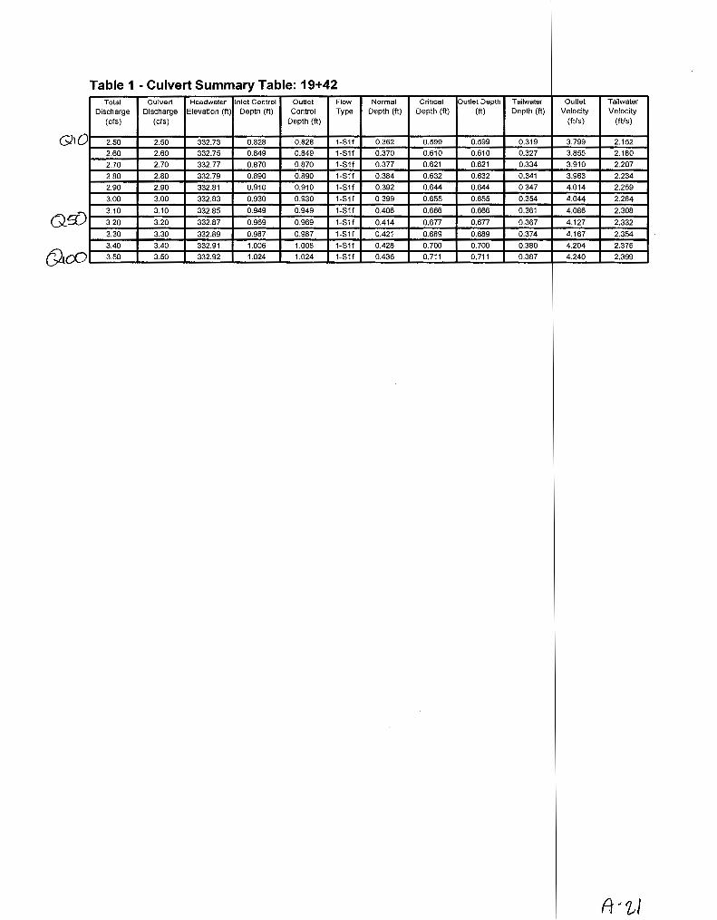
Table 1 -Culvert Summary Table: 19+42 Total Culvert Headwater Inlet Control Outlet Flow Normal Critical Outlet Depth Tailwater Outlet Tailwater
Discharge Discharge Elevation (ft) Depth (ft) Control Type Depth (ft) Depth (ft) (ft) Depth (ft) Velocity Velocity (cfs) (cfs) Depth (ft) (ft/s) (11/s)
Q10 2.50 2.50 332.73 0.828 0.828 1-811 0.362 0.599 0.599 0.319 3.799 2.152
2.60 2.60 332.75 0.849 0.849 1-811 0.370 0.610 0.610 0.327 3.855 2.180
2.70 2.70 332.77 0.870 0.870 1-81f 0.377 0.621 0.621 0.334 3.910 2.207
2.80 2.80 332.79 0.890 0.890 1-811 0.384 0.632 0.632 0.341 3.963 2.234
2.90 2.90 332.81 0.910 0.910 1-Stf 0.392 0.644 0.644 0.347 4.014 2.259
3.00 3.00 332.83 0.930 0.930 1-Stf 0.399 0.655 0.655 0.354 4.044 2.284
3.10 3.10 332.85 0.949 0.949 1-Stf 0.406 0.666 0.666 0.361 4.086 2.308
3.20 3.20 332.87 0.969 0.969 1-81f 0.414 0.677 0.677 0.367 4.127 2.332 Qif) 3.30 3.30 332.89 0.987 0.987 1-Stf 0.421 0.689 0.689 0.374 4.167 2.354
3.40 3.40 332.91 1.006 1.006 1-Stf 0.428 0.700 0.700 0.380 4.204 2.376
CYLoO 3.50 3.50 332.92 1.024 1.024 1-81f 0.436 0.711 0.711 0.387 4.240 2.399
A·tJ

********************************************************************************
Inlet Elevation (invert): 331.90 ft, Outlet Elevation (invert): 330.53 ft
Culvert Length: 50.02 ft, Culvert Slope: 0.0274
********************************************************************************
A/z~

Culvert Performance Curve Plot: 19+42
......., ~
c 0
332.90
il 332.85 > Qj
w '-Qj
~ 332.80 ~
u ro (11
I
332.75
Perfon11ance Curve Culvert: 19-'-42
[I] w Inlet Control Elev Outlet Control E!ev
2.6 2.8 3.0 3.2 3.4 Tatar Discharge (cfs)
ft-<2-j
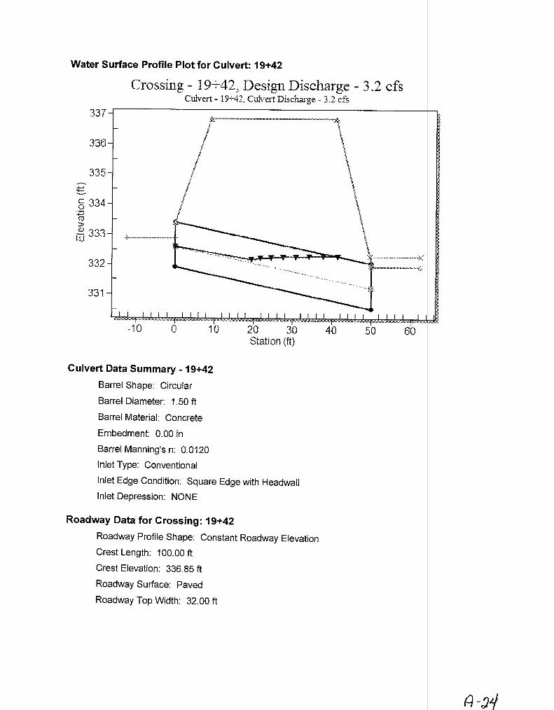
Water Surface Profile Plot for Culvert: 19+42
Crossing- 19+42, Design Discharge- 3.2 cfs Culvert- 19--42, Culvert Discharge- 3.2 d's
337
33f3
335 ......, ~
§ 334 ......, (1J
> G) 333 w
332
331
0
Culvert Data Summary - 19+42
Barrel Shape: Circular
Barrel Diameter: 1.50 ft
Barrel Material: Concrete
Embedment: 0.00 in
Barrel Manning's n: 0.0120
Inlet Type: Conventional
Inlet Edge Condition: Square Edge with Headwall
Inlet Depression: NONE
Roadway Data for Crossing: 19+42
Roadway Profile Shape: Constant Roadway Elevation
Crest Length: 100.00 ft
Crest Elevation: 336.85 ft
Roadway Surface: Paved
Roadway Top Width: 32.00 ft
,.,. ----------------~x
~ (;
(:}~~1

Table 1- C ulvert Summary Tabl~ 9/tr Total C lvert Headwater Inlet Control Outlet Flow Normal Critical Outlet Depth Tailwater Outlet Tailwater
Discharge Dis harge Elevation (It) Depth (It) Control Type Depth (ft) Depth (It) (It) Depth (It) Velocity Velocity (cis) ( Is) Depth (It) (Ills) (Ills)
D 4.80 .80 332.23 1.261 o.o· 1-S2n 0.703 0.839 0.708 0.705 5.846 1.998
5.01 .01 332.27 1.296 o.o· 1-S2n 0.721 0.859 0.723 0.720 5.940 2.022
5.22 .22 332.30 1.330 o.o· 1-S2n 0.739 0.878 0.739 0.736 6.017 2.045
5.43 .43 332.33 1.365 0.0* 1-S2n 0.757 0.898 0.757 0.750 6.075 2.067
5.64 .64 332.37 1.399 o.o· 1-S2n 0.774 0.915 0.774 0.765 6.136 ?.088
5.85 .85 332.40 1.434 o.o• 1-S2n 0.791 0.931 0.791 0.779 6.193 2.109
6.06 .06 332.44 1.469 o.o• 1-S2n 0.808 0.948 0.810 0.793 6.228 2.129
0 6.10 .10 332.45 1.476 o.o· 1-S2n 0.811 0.951 0.813 0.796 6.239 2.133
6.48 .48 332.51 1.540 o.o• 5-S2n 0.842 0.981 0.844 0.821 6.328 2.168
6.69 .69 332.55 1.577 o.o· 5-S2n 0.859 0.998 0.861 0.834 6.379 2.187
r u 6.90 .90 332.58 1.614 o.o• 5-S2n 0.877 1.014 0.877 0.847 6.428 2.205
JJJ iQ Jso ~qllrNJ
..
A-a 5

* the retical depth is impractical. Depth reported is corrected.

********************************************************************************
Inlet Elevation (invert): 330.97 ft, Outlet Elevation (invert): 330.53 ft
Culvert Length: 50.00 ft, Culvert Slope: 0.0088
********************************************************************************

Culvert Pe formance Curve Plot: 26+40
Perfonnance Curve Culvert: 26·'--41}
00 [iJ Inlet Contra! Elev Outlet Control Elev
332.60-h---------------------------.
332.55
~ 332.50 c 0
~ 332.45 •3)
~ 332.40 Q)
-1--' (lj
s 332.35 TI (lj Q)
I 332.30
332.25
5.0 5~5 6~0 7.0 Total Discharge (cfs)
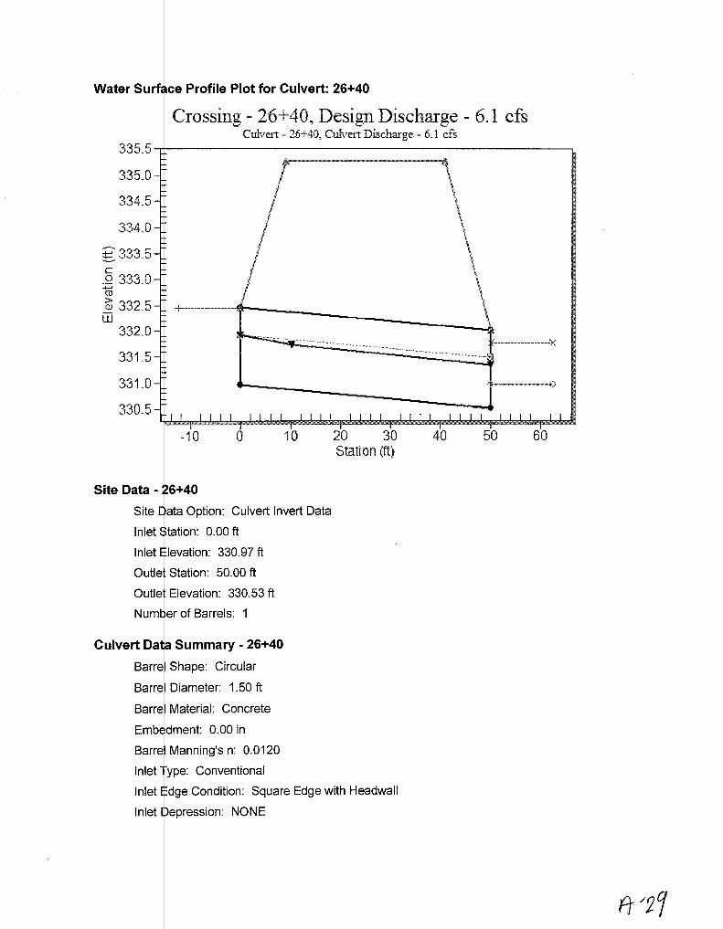
Water Surf ce Profile Plot for Culvert: 26+40
Crossing - 26 ; 40, Design Discharge - 6.1 cfs Culvert - 26-'-40, Culvert Discharge - 6.1 cfs
335_5
335_0
334 .. 5
334.0
;t:: 333.5 c -~ 333.0 .... 0J
~ 332.5 w
332.0
331.5
331.0
330.5
Site Data
Site
! I /
I I I I
Culvert Invert Data
levation: 330.97 ft
Culvert Da Summary - 26+40
Barr I Shape: Circular
Barrel Diameter: 1.50 ft
Barre Material: Concrete
Emb dment: 0.00 in
Barre Manning's n: 0.0120
Inlet ype: Conventional
Inlet dge Condition: Square Edge with Headwall
Inlet epression: NONE
\ \
\ --9

Table 1- C ~lvert Summary Table: 75+50 Total Cu vert Headwater Inlet Control Outlet Flow Normal Critical Outlet Depth Tailwater Outlet Tailwater
Discharge Dis c arge Elevation (ft) Depth (ft) Control Type Depth (ft) Depth (ft) (ft) Depth (ft) Velocity Velocity (cfs) ( fs) Depth (ft) (ft/s) (ft/s)
10 5.80 1.80 280.40 n.39§) o.o• 1-S2n 0.489 0.927 0.496 0.591 11.461 3.084
6.03 L03 280.43 1.435 o.o· 1-S2n 0.498 0.946 0.505 0.603 11.509 3.118
6.26 L26 280.47 1.474 o.o• 1-S2n 0.508 0.964 0.513 0.615 11.687 3.151
6.49 L49 280.51 1.513 o.o· 5-S2n 0.518 0.982 0.521 0.627 11.858 3.183
6.72 f.72 280.55 1.553 o.o• 5-S2n 0.528 1.000 0.533 0.638 11.894 3.214
6.95 L95 280.59 1.593 o.o• 5-S2n 0.538 1.018 0.543 0.650 11.999 3.243
7.18 .18 280.63 1.635 o.o• 5-S2n 0.547 1.037 0.551 0.661 12.169 3.273 !1)- 7.30 .30 280.66 (1":65V o.o· 5-S2n 0.552 1.046 0.559 0.666 12.149 3.288
7.64 .64 280.72 1.721 o.o· 5-S2n 0.567 1.069 0.605 0~682 11.458 3.330 7.87 .87 280.76 1.765 o.o· 5-S2n 0.577 1.084 0.616 0.693 11.531 3.357
100 8.10 uo 280.81 ~<D o.o· 5-S2n 0.586 1.099 0.627 0.703 11.604 3.384
A:3 0

*the retical depth is impractical. Depth reported is corrected.

********************************************************************************
Inlet Elevation (invert): 279.00 ft, Outlet Elevation (invert): 276.60 ft
Culvert Length: 50.06 ft. Culvert Slope: 0.0480
********************************************************************************

Culvert Per ormance Curve Plot: 75+50
280.80
~280.75 _.__. ~
c 280.70 0
~ 280.65 (])
w 280 .. 60 '--(])
1280.55 -o ?E 280.50 I
280.45
280.40
Perfom1ance Curve Culvert: 75+50
00 rn Inlet Control Elev Outlet Control Elev
6.0 6.5 7.0 7.5 Total Discharge (cfs)
8.0

Water Su ce Profile Plot for Culvert: 75+50
Crossing- 75+50, Design Discharge- 7.3 cfs Culveti- 75..;..50
0 Culvert Discharge - 7.3 cfs
284
283
282
~281 c 0
-m 280 i]) w
279
278
277
-10
Site Data - 75+50
0 10 20 30 Station (ft)
Site ata Option: Culvert Invert Data
Inlet tation: 0.00 ft
Inlet Elevation: 279.00 ft
Outl t Station: 50.00 ft
Outl t Elevation: 276.60 ft
Number of Barrels: 1
Culvert D a Summary - 75+50
Barr I Shape: Circular
Barr I Diameter: 1.50 ft
Barr I Material: Concrete
Barr I Manning's n: 0.0120
Inlet ype: Conventional
Inlet Edge Condition: Square Edge with Headwall
Inlet Depression: NONE
40 50 60

180
168
156
144
EXAMPLE
0•42 lnchH (3.~ fHt) 0•120 ch
.tm' * HW 0 fe1t
(I) 2., s.e (21 2.1 7.4
(3) 2.2 7.7
1 0 in feet
To uat scale (21 or (3) project horlzontall, to scale (1), then uu stralgllt lllclined line tllrougll 0 ond Q scot .. , or reverse oa illustrated.
(I) (2) ·(3)
f. I-f ,"2-
1.0
.9
.8
.6
HEADWATER S(!ALES 2 83
'HEADWATER DEPTH FOR CONCRETE PIPE CULVERTS
WITH INLET CONTROL BUREAU OF PUBLIC. ROADS JAN. 1983
REVISED MAY 1964
181

288
287
286
285
284 ,..-..._
.:= .......... c 0 283 ~ Q.)
w 282
281
280
279
~ 278
' (:N ~
-20
Crossing- 85+50, Design Discharge- 30.2 cfs , Culvert- 85+50, Culvert Discharge- 30.2 cfs r:::J . .$1e0/tretJ,.
1>---------------~----~--~'"""""'"""'"""'"'""""~"-~~-"-~-&
I \ / ~ j ' /' \
i ~ i '\
I \
\ \ \
I \ I \ ' \ ,t' '\
' < ' \ j \
' \ I ' ' I
//
' < . ' . \ +- - --j \ I \
\
\ \ \ \
\ ~.
.~~-~~""'~~"'""''"'-@
-10 0 10 20 30 40 50 60 70 80 Station (ft)
I

Table 1 - SL mmary of Culvert Flows at Crossing: 85+50 Headwater Ele ation Total Discharge (cfs) 85+50 Discharge (cfs) Roadway Discharge Iterations
~ ~
!D 283.29 16.50 16.50 0.00 1 283.45 18.59 18.59 0.00 1 283.61 20.68 20.68 0.00 1 283.78 22.77 22.77 0.00 1 283.95 24.86 24.86 0.00 1 284.12 26.95 26.95 0.00 1 284.31 29.04 29.04 0.00 1
!)0~--~2~8~4.~42~---r----~30~·~20~0~~~'+---~3~0.~20~---+-----0~.0~0~--~------1~----~ 284.73 33.22 33.22 0.00 1 284.96 35.31 35.31 0.00 1
\ 285.20 37.40 37.40 0.00 1
1 00 '----2;;..;8~7.;.;;.9~0+-----5;;..;5~.0;...4 __ ....._ __ ..;5~5..;.0~4 ______ ..;o;.;.;.o;..;;o __ --~, __ o.;.v.;..;e;.;.;rt;.;.opi;..:;p;.;.;in.;..:g'-__,

Table 2- C ~lvert Summary Table: 85+50 Total Cu vert Headwater Inlet Control Outlet Flow Normal Critical Outlet Depth Tailwater Outlet Tailwater
Discharge Disc arge Elevation (ft) Depth (ft) Control Type Depth (ft) Depth (ft) (ft) Depth (ft) Velocity Velocity (cfs) ( fs) Depth (ft) (ft/s) (ft/s)
16.50 1 .50 283.29 1.993 o.o· 1-S2n 0.672 1.367 0.683 1.229 15.097 2.458
18.59 1 .59 283.45 2.153 o.o· 1-S2n 0.719 1.458 0.788 1.305 14.073 2.539
20.68 2 .68 283.61 2.313 o.o· 1-S2n 0.763 1.541 0.764 1.376 16.287 £.612
22.77 2 .77 283.78 2.476 o.o· 1-S2n 0.799 1.618 0.883 1.443 14.638 2.680
24.86 2 .86 283.95 2.645 o.o· 5-S2n 0.836 1.695 0.933 1.507 14.851 2.743
26.95 2 .95 284.12 2.823 o.o· 5-S2n 0.872 1.768 0.981 1.568 15.074 2.802
29.04 2 .04 284.31 3.011 o.o· 5-S2n 0.908 1.831 1.026 1.626 15.325 2.857
30.20 3 .20 284.42 . r 3.121) o.o• 5-S2n 0.928 1.866 1.051 1.657 15.412 2.887
33.22 3 .22 284.73 3.427 o.o· 5-S2n 0.981 1.957 1.115 1.735 15.682 2.960
35.31 3 .31 284.96 3.656 o.o• 5-S2n 1.015 2.014 1.159 1.786 15.850 3.007
1 oo~ 37.40 3 .40 285.20" ~ o.o· 5-S2n 1.046 2.058 1.201 1.836 16.036 3.053
A-sg

* the retical depth is impractical. Depth reported is corrected.

Site Data
********************************************************************************
Inlet Elevation (invert): 281.30 ft, Outlet Elevation (invert): 277.90 ft
Culvert Length: 65.09 ft, Culvert Slope: 0.0523
********************************************************************************
Site ata Option: Culvert Invert Data
Inlet tation: 0.00 ft
Inlet levation: 281.30 ft
Outl Station: 65.00 ft
Outl t Elevation: 277.90 ft
er of Barrels: 1
Culvert Da Summary - 85+50
Barr I Shape: Circular
Barr I Diameter: 2.50 ft ·
Barr
Inlet ype: Conventional
Inlet dge Condition: Square Edge with Headwall
Inlet epression: NONE

Table 3-D >wnstream Channel Rating Curve {Crossing: 85+50)
Flow (cfs) Water Surface Depth (ft) Velocity (ft/s) Shear (psf} Froude Number Elev (ft)
16.50 279.13 1.23 2.46 0.46 0.47 18.59 279.21 1.31 2.54 0.49 0.47 20.68 279.28 1.38 2.61 0.52 0.48 22.77 279.34 1.44 2.68 0.54 0.48 24.86 279.41 1.51 2.74 0.56 0.48 26.95 279.47 1.57 2.80 0.59 0.48 29.04 279.53 1.63 2.86 0.61 0.49 30.20 279.56 1.66 2.89 0.62 0.49 33.22 279.63 1.73 2.96 0.65 0.49 35.31 279.69 1.79 3.01 0.67 0.49 37.40 279.74 1.84 3.05 0.69 0.49

Tailwater Channel Data - 85+50
Tailw ter Channel Option: Trapezoidal Channel
Botto Width: 3.00 ft
Side lope (H:V): 2.00 (_:1)
Chan el Slope: 0.0060
Chan el Manning's n: 0.0400
Chan el Invert Elevation: 277.90 ft
Roadway ata for Crossing: 85+50
Road ay Profile Shape: Constant Roadway Elevation
Cres Length: 50.00 ft
ay Surface: Paved
ay Top Width: 32.00 ft
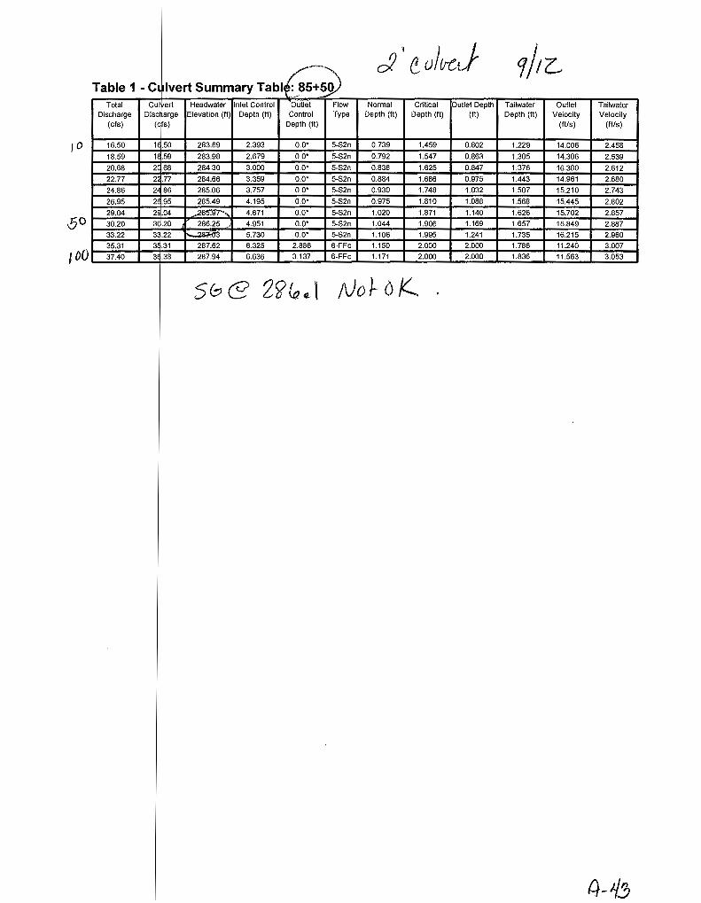
lvert Summary Tabl~ cJ' tulu-J 1/r~
Table 1- C1 Total Cui ert Headwater Inlet Control Outlei Flow Normal Critical Outlet Depth Tailwater Outlet Tailwater
Discharge Disc arge Elevation (It) Depth (It) Control Type Depth (It} Depth (It) (It) Depth (It} Velocity Velocity (cis) (c s) Depth (It) (Ills) (Ills)
,o 16.50 1 .50 283.69 2.393 o.o· 5-S2n 0.739 1.459 0.802 1.229 14.006 2.458
18.59 1 .59 283.98 2.679 o.o• 5-S2n 0.792 1.547 0.863 1.305 14.306 2.539
20.68 2 .68 284.30 3.000 o.o• 5-S2n 0.838 1.625 0.847 1.376 16.380 2.612
22.77 2 .77 284.66 3.359 o.o• 5-S2n 0.884 1.686 0.975 1.443 14.961 2.680
24.86 2 .86 285.06 3.757 o.o· 5-S2n 0.930 1.748 1.032 1.507 15.210 2.743
26.95 2 .95 285.49 4.195 o.o· 5-S2n 0.975 1.810 1.088 1.568 15.445 2.802
29.04 2 .04 ~ ... 4.671 o.o· 5-S2n 1.020 1.871 1.140 1.626 15.702 2.857
30.20 3 .20 286.25 4.951 o.o· 5-S2n 1.044 1.906 1.169 1.657 15.849 2.887
33.22 3 .22 ?~ 5.730 o.o· 5-S2n 1.106 1.995 1.241 1.735 16.215 2.960
35.31 3 .31 287.62 6.325 2.886 6-FFc 1.150 2.000 2.000 1.786 11.240 3.007
100 37.40 3 .33 287.94 6.636 3.137 6-FFc 1.171 2.000 2.000 1.836 11.563 3.053
58@ 2~lo ¢' f\)o J-- o K
tl-1:!;

* the retical depth is impractical. Depth reported is corrected.

********************************************************************************
Inlet Elevation (invert): 281.30 ft, Outlet Elevation (invert): 277.90 ft
Culvert Length: 65.09 ft, Culvert Slope: 0.0523
********************************************************************************

Culvert Pe ormance Curve Plot: 85+50
~
288.0
287.5
~287.0 c ~ 286.5 co > (]) 286 0 w· .
2 285.5 co
~ 285.0 co (])
I 284.5
284.0
Perfom1ance Curve Culvert: 85+50
[I] 00 Inlet Control Etev Outlet Control Elev
20 25 30 Total Discharge (cfs)

Water Surfa e Profile Plot for Culvert: 85+50
Crossing- 85+50, Design Discharge- 30.2 cfs Culvert- 85-'-50, Culvert Discharge- 30.2 .cfs
288
287
286
285
'E- 284 c ~ 283 (1)
~ 282 w
281
280
279
278
-20 0
Culvert Da a Summary - 85+50
Barr I Shape: Circular
Barr I Diameter: 2.00 ft
Barr I Material: Concrete
Barr I Manning's n: 0.0120
Inlet ype: Conventional
20 40 Station (ft)
dge Condition: Square Edge with Headwall
epression: NONE
60 80

Table 2 - De wnstream Channel Rating Curve (Crossing: 85+50)
Flow (cfs)
16.50 18.59 20.68 22.77 24.86 26.95 29.04 30.20 33.22 35.31 37.40
Water Surface Elev (ft)
279.13 279.21 279.28 279.34 279.41 279.47 279.53 279.56 279.63 279.69 279.74
Depth (ft)
1.23 1.31 1.38 1.44 1.51 1.57 1.63 1.66 1.73 1.79 1.84
Velocity (ft/s) Shear (psf)
2.46 0.46 2.54 0.49 2.61 0.52 2.68 0.54 2.74 0.56 2.80 0.59 2.86 0.61 2.89 0.62 2.96 0.65 3.01 0.67 3.05 0.69
Froude Number
0.47 0.47 0.48 0.48 0.48 0.48 0.49 0.49 0.49 0.49 0.49

Tailwater C annel Data- 85+50
Tailw ter Channel Option: Trapezoidal Channel
Botto Width: 3.00 ft
Side lope (H:V): 2.00 (_:1)
Chan el Slope: 0.0060
Chan el Manning's n: 0.0400
Chan ellnvert Elevation: 277.90 ft
Roadway ata for Crossing: 85+50
Road ay Profile Shape: Constant Roadway Elevation
Crest Length: 50.00 ft
ay Surface: Paved
ay Top Width: 32.00 ft
(-1 ·-1-/1

Water Surf ce Profile Plot for Culvert: 94+71
Crossing - 94 + 71, Design Discharge - 91.0 cfs Culvert- 94-i-71, Culvert Discharge- 91.1} d's.
·· . .,._
288
286
284 .~ ....... ...._
~282 0
::;::::; (iJ
> 280 @
w 278
276
274
20 0 20 40 60 80 100 Station {ft)

Table 1- Ct lvert Summary Table: 94+71 Total Cu I ert Headwater Inlet Control Outlet Flow Normal Critical Outlet Depth Tailwater Outlet Tailwater
Discharge Disc arge Elevation (ft) Depth (ft) Control Type Depth (ft) Depth (ft} (ft) Depth (ft) Velocity Velocity (cfs} (c s) Depth (ft) (ft/s) (ft/s)
D 51.00 51 00 279.45 2.997 o.o• 1-S2n 1.115 2.136 1.262 1.292 14.977 7.068
57.00 57 00 279.65 3.197 o.o· 1-S2n 1.191 2.264 1.344 1.366 15.320 7.282
63.00 63 00 279.84 3.393 o.o· 1-S2n 1.250 2.393 1.430 1.435 15.565 7.478
69.00 69 00 280.04 3.586 o.o• 1-S2n 1.308 2.503 1.512 1.501 15.827 7.661
75.00 75 00 280.23 3.782 o.o· . 1-S2n 1.366 2.612 1.591 1.563 16.094 7.832
81.00 81 00 280.43 3.981 o.o· 1-S2n 1.423 2.721 1.668 1.623 16.317 7.992
87.00 87 00 280.64 4.187 o.o• 5-S2n 1.481 2.825 1.744 1.680 16.527 8.143
0 s 91.00 91 00 280.78 ( 4.329) o.o· 5-S2n 1.520 2.884 1.792 1.717 16.676 8.239
99.00 99 00 281.08 4.625 o.o· 5-S2n 1.596 3.003 1.887 1.788 16.968 8.423
105.00 10 .00 281.31 4.860 o.o• 5-S2n 1.647 3.092 1.957 1.839 17.174 8.552
UL V' 111.00 11 .00 281.56 t: 5.107.) o.o· 5-S2n 1.697 3.182 2.028 1.888 17.362 8.677
A 5/
* theo etical depth is impractical. Depth reported is corrected.

********************************************************************************
Inlet Elevation (invert): 276.45 ft, Outlet Elevation (invert): 273.41 ft
Culvert Length: 85.05 ft, Culvert Slope: 0.0358
********************************************************************************
Culvert Invert Data
Outlet tation: 85.00 ft
Outlet levation: 273.41 ft
r of Barrels: 1
Culvert Oat Summary- 94+71
Barrel Shape: Circular
Barrel Diameter: 4.00 ft
Barrel Material: Concrete
Embe ment: 0.00 in
Barrel Manning's n: 0.0120
Inlet T pe: Conventional
Inlet E ge Condition: Grooved End in Headwall
Inlet epression: NONE

Table 2- Do r,vnstream Channel Rating Curve (Crossing: 94+71)
Flow (cfs) Water Surface Depth (ft} Velocity (ft/s) Shear (psf) Froude Number Elev (ft)
51.00 274.70 1.29 7.07 2.90 1.33 57.00 274.78 1.37 7.28 3.07 1.33 63.00 274.85 1.44 7.48 3.22 1.34 69.00 274.91 1.50 7.66 3.37 1.35 75.00 274.97 1.56 7.83 3.51 1.36 81.00 275.03 1.62 7.99 3.65 1.36 87.00 275.09 1.68 8.14 3.77 1.37 91.00 275.13 1.72 8.24 3.86 1.37 99.00 275.20 1.79 8.42 4.02 1.38 105.00 275.25 1.84 8.55 4.13 1.38 111.00 275.30 1.89 8.68 4.24 1.39
Ft-51

Tailwater C annel Data- 94+71
Tailwa er Channel Option: Trapezoidal Channel
Botto Width: 3.00 ft
SideS ope (H:V): 2.00 (_:1)
I Slope: 0.0360
I Manning's n: 0.0350
I Invert Elevation: 273.41 ft
Roadway D ta for Crossing: 94+71
Road ay Profile Shape: Constant Roadway Elevation
ength: 50.00 ft
levation: 288.45 ft
Road ay Surface: Paved
Road ay Top Width: 32.00 ft

:\) (i\ ~
288
286
284
£282 '-"' r::: 0
:.;:::::;
~ Q) w 280
278
276
274
Crossing- 94+71, Design Discharge- 91.0 cfs Culvert- 94+71, Culve1t Discharge- 91.0 cfs 3'( N
0
&-~~~-----------------=--------~------=-----=-~-& I \
; \ I .. ' -' ., I \
I \ ; \ ! \
I \ ! \
! \ { \
I \ I \
! \
/ \ ! ., ! \
{ \ ' \ .' ~ +·············--····· ··············································:t \
l ~. I \
-20
I ' { ' ' ' i )
! \ ! \
I \ ! ' <" \
i '· ; \ ( \ . \
\ \ \
0 20 40 Station (ft)
60
\ \ \
80
I
-~~~-==~--~-----~---e
100

3 Table 2- Cu vert Summary Table: 94+71
Total Cui v rt Headwater Inlet Control Outlet Flow Normal Critical Outlet Depth Tailwater Outlet Tai\water Discharge Disch rge Elevation (ft) Depth (ft) Control Type Depth (ft) Depth (ft) (ft) Depth (ft) Velocity Velocity
(cfs) (cf ) Depth (ft) (ft/s) (fils)
lD 51.00 51. 0 280.09 3.636 o.o· 5-S2n 1.265 2.316 1.425 1.292 15.406 7.068
57.00 57. 0 280.47 4.025 o.o· 5-S2n 1.346 2.437 1.526 1.366 15.777 7.282
63.00 63.DO 280.90 4.455 o.o· 5-S2n 1.427 2.534 1.624 1.435 16.142 7.478
69.00 69. 0 281.38 4.927 o.o• 5-S2n 1.507 2.630 1.720 1.501 16.469 7.661
75.00 75. 0 281.89 5.440 o.o• 5-S2n 1.583 2.726 1.814 1.563 16.775 7.832
81.00 81. 0 282.44 5.992 o.o· 5-S2n 1.660 2.823 1.903 1.623 17.156 7.992
87.00 87.00 283.03 6.579 o.o· 5-S2n 1.736 2.919 1.991 1.680 17.493 8.143 so 91.00 91.00 283.44 /"6.989) o.o· 5-S2n 1.787 2.983 2.047 1.717 17.725 8.239
99.00 99. 0 284.30 T.853 5.203 6-FFc 1.893 3.000 3.000 1.788 14.006 8.423
105.00 10 5 00 284.99 8.537 5.858 6-FFc 1.972 3.000 3.000 1.839 14.854 8.552
/DO, 111.00 111 .00 285.74 /"9.292) 6.551 6-FFc 2.052 3.000 3.000 1.888 15.703 8.677 ~
No
5b-- .,.. - cR~S, 1 !3oT HwjD>:L- ·
A-·57

Site Data- 9 +71
********************************************************************************
Inlet Elevation (invert): 276.45 ft, Outlet Elevation (invert): 273.41 ft
Culvert Length: 85.05 ft, Culvert Slope: 0.0358
********************************************************************************
SiteD ta Option: Culvert Invert Data
InletS ation: 0.00 ft
Inlet E evation: 276.45 ft
Outlet Station: 85.00 ft
Outlet Elevation: 273.41 ft
r of Barrels: 1
Culvert Oat Summary - 94+ 71
Barrel Shape: Circular
Barrel Diameter: 3.00 ft
Barrel Material: Concrete
Embe ment: 0.00 in
Inlet T pe: Conventional
Inlet dge Condition: Grooved End in Headwall
Inlet epression: NONE

Table 3- Do fvnstream Channel Rating Curve (Crossing: 94+71)
Flow (cfs) Water Surface Depth (ft) Velocity (ft/s) Shear (psf) Froude Number Elev (ft)
51.00 274.70 1.29 7.07 2.90 1.33 57.00 274.78 1.37 7.28 3.07 1.33 63.00 274.85 1.44 7.48 3.22 1.34 69.00 274.91 1.50 7.66 3.37 1.35 75.00 274.97 1.56 7.83 3.51 1.36 81.00 275.03 1.62 7.99 3.65 1.36 87.00 275.09 1.68 8.14 3.77 1.37 91.00 275.13 1.72 8.24 3.86 1.37 99.00 275.20 1.79 8.42 4.02 1.38 105.00 275.25 1.84 8.55 4.13 1.38 111.00 275.30 1.89 8.68 4.24 1.39
ft·s9

Tailwater C annel Data- 94+71
Tailw ter Channel Option: Trapezoidal Channel
Botto Width: 3.00 ft
Side lope (H:V): 2.00 (_:1)
Chan el Slope: 0.0360
Chan el Manning's n: 0.0350
Chan ellnvert Elevation: 273.41 ft
Roadway D ta for Crossing: 94+71
ay Profile Shape: Constant Roadway Elevation
ength: 50.00 ft
levation: 288.45 ft
ay Surface: Paved
ay Top Width: 32.00 ft

Table 1- Cu vert Summary Ta~ 2.6' &-t.lveJ 4 z (-}CA-t ch (,U 11Cl tf tl-Total Cui v rt Headwater Inlet Control "--:Outlet ~ow Normal Critical Outlet Depth Tailwater Outlet Tailwater
Discharge Disch age Elevation (ft) Depth (ft) ~ Type Depth (ft) Depth (ft) (ft) Depth (ft) Velocity Velocity (cfs) (cfs Depth (ft) (ft/s) (ft/s)
17.00 17. 0 283.39 2.077 0.044 1-S2n 0.945 1.389 1.023 0.824 9.002 4.438 19.10 19.10 283.55 2.238 0.096 1-S2n 1.010 1.480 1.094 0.876 9.237 4.587
21.20 21. 0 283.71 2.399 0.145 1-S2n 1.068 1.561 1.078 0.925 10.462 4.723 23.30 23. 0 283.87 2.564 0.192 5-S2n 1.126 1.638 1.229 0.972 9.703 4.849
25.40 25. 0 284.05 2.736 0.236 5-S2n 1.184 1.715 1.296 1.016 9.891 4.966
27.50 27. 0 284.23 2.917 0.279 5-S2n 1.242 1.784 1.361 1.059 10.070 5.075
29.60 29. 0 284.42 3.110 0.319 5-S2n 1.297 1.848 1.423 1.099 10.267 5.179
~ 31.00 31. 0 284.56 _.. 3.245;:) 0.346 5-S2n 1.334 1.890 1.464 1.126 10.384 5.245
33.80 33. 0 284.84 3.535 0.396 5-S2n 1.407 1.974 1.543 1.176 10.621 5.369
35.90 35. 0 285.08 3.769 0.433 5-S2n 1.462 2.026 1.608 1.213 10.772 5.457
38.00 38. 0 285.33 4.020 0.468 5-S2n 1.517 2.071 1.664 1.248 10.969 5.541
A ·&I

********************************************************************************
Inlet Elevation (invert): 281.31 ft, Outlet Elevation (invert): 280.53 ft
Culvert Length: 50.01 ft, Culvert Slope: 0.0156
********************************************************************************
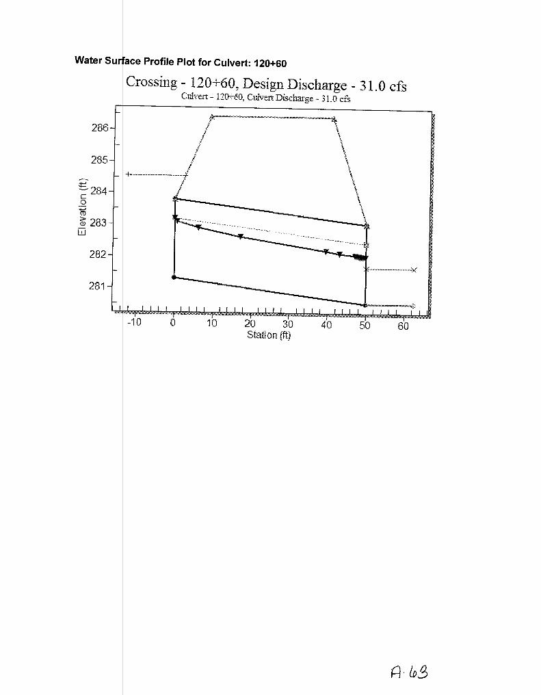
Summary - 120+60
hape: Circular
aterial: Concrete
Inlet T pe: Conventional
Inlet E ge Condition: Square Edge with Headwall
Water Su ace Profile Plot for Culvert: 120+60
286
285
~
~284 c 0
........ (V
1D 283 w
282
281
Crossing- 120: 60, Design Discharge- 31.0 cfs Culvert - 12~60, Culvert Discharge - 31_{} cfs
-10 0 10 20 30 Station (ft)
' :-----------------)('
40 50 60

Water Surf ce Profile Plotfor Culvert: 120+60 j I w~ Flows 1{/) Crossing- 120+60, DesignDischarge_- 13.8 cfs c?uunarfJcu.-£ ·::?
286
285
... ~284 c 0 ... (1)
~ 283 w
282
281
Culvert- 12lF-60, Culvert Dtscharge- 13.8 cfs. I 0 • '4 (AJ,.() •
10 20 30 Station (ft)
40
---··-------------)(
50 60

Table 1- CL lvert Summary Table: 120+60 Total Cu I ert Headwater Inlet Control Outlet Flow Normal Critical Outlet Depth Tailwater Outlet Tailwater
Discharge Disc herge Elevation (It) Depth (It) Control Type Depth (ft) Depth (ft) (ft) Depth (It) Velocity Velocity (cis) (c s) Depth (ft) (ft/s) (ftls)
7.30 7. 0 282.70 1.391 o.o· 1-S2n 0.660 0.956 0.665 0.521 7.960 3.465
8.30 8. 0 282.82 1.506 o.o· 1-S2n 0.706 1.024 0.741 0.560 7.817 3.601
9.30 9. 0 282.93 1.616 o.o· 1-S2n 0.752 1.085 0.754 0.596 8.563 3.726
10.30 10 30 283.03 1.723 o.o· 1-S2n 0.798 1.146 0.799 0.630 8.789 3.841
11.30 11 30 283.14 1.829 o.o• 1-S2n 0.839 1.206 0.840 0.662 9.049 3.946
12.30 12 30 283.25 1.937 o.o· 1-S2n 0.879 1.257 0.886 0.693 9.151 4.045
13.30 13 30 283.36 2.047 o.o· 5-S2n 0.919 1.308 0.923 0.723 9.386 4.138
13.80 (1 3®" 283.41 2.103 o.o· 5-S2n 0.939 1.334 0.946 0.737 9.423 4.182
15.30 15 30 283.59 2.279 o.o• 5-S2n 0.999 1.409 1.064 0.779 9.012 4.308
16.30 16 30 283.71 2.404 0.026 5-S2n 1.037 1.451 1.106 0.806 9.151 4.386
17.30 17 30 283.85 2.535 0.052 5-S2n 1.075 1.493 1.147 0.832 9.286 4.460
A- tos

* thea etical depth is impractical. Depth reported is corrected.

Site Data - 1 0+60
********************************************************************************
Inlet Elevation (invert): 281.31 ft, Outlet Elevation (invert): 280.53 ft
Culvert Length: 50.01 ft, Culvert Slope: 0.0156
********************************************************************************
SiteD ta Option: Culvert Invert Data
InletS ation: 0.00 ft
Inlet E evation: 281.31 ft
Outlet Station: 50.00 ft
Outlet Elevation: 280.53 ft
r of Barrels: 1
Culvert Oat Summary -120+60
Barrel Shape: Circular
Barrel Diameter: 2.00 ft
Barrel Material: Concrete
Embe ment: 0.00 in
Inlet ype: Conventional
Inlet dge Condition: Square Edge with Headwall
Inlet epression: NONE

Table 2- D oNnstream Channel Rating Curve (Crossing: 120+60)
Flow (cfs) Water Surface Depth (ft) Velocity (ft/s) Shear (psf) Froude Number Elev (ft)
7.30 281.05 0.52 3.46 0.98 0.95 8.30 281.09 0.56 3.60 1.05 0.96 9.30 281.13 0.60 3.73 1.11 0.96 10.30 281.16 0.63 3.84 1.18 0.97 11.30 281.19 0.66 3.95 1.24 0.98 12.30 281.22 0.69 4.05 1.30 0.98 13.30 281.25 0.72 4.14 1.35 0.99 13.80 281.27 0.74 4.18 1.38 0.99 15.30 281.31 0.78 4.31 1.46 1.00 16.30 281.34 0.81 4.39 1.51 1.00 17.30 281.36 0.83 4.46 1.56 1.00
A LPF

Tailwater C annel Data -120+60
Tailwa er Channel Option: Trapezoidal Channel
Botto Width: 3.00 ft
SideS ope (H:V): 2.00 (_:1)
I Slope: 0.0300
I Manning's n: 0.0400
I Invert Elevation: 280.53 ft
Roadway D ta for Crossing: 120+60
ay Profile Shape: Constant Roadway Elevation
ength: 50.00 ft
levation: 286.43 ft
ay Surface: Paved
ay Top Width: 32.00 ft

Table 1- C ~lvert Summary Table: 129+55 j: s 1
Total Cu I ert Headwater Inlet Control Outlet Flow Normal Critical Outlet Depth Tailwater Outlet Tailwater Discharge Disc arge Elevation (ft) Depth (ft) Control Type Depth (ft) Depth (ft) (ft) Depth (ft) Velocity Velocity
(cfs) (cfs) Depth (ft) (ft/s) (ft/s)
23.00 2 .00 273.02 2.265 o.o· 1-S2n 1.009 1.541 1.110 0.093 9.654 82.763
25.80 2 .80 273.19 2.432 0.0* 1-S2n 1.073 1.633 1.189 0.099 9.886 86.503
28.60 2 .60 273.36 2.595 o.o· 1-S2n 1.137 1.726 1.264 0.106 10.104 89.894
31.40 3 .40 273.52 2.758 o.o· 1-S2n 1.200 1.816 1.336 0.112 10.314 93.194
34.20 3< .20 273.68 2.922 o.o· 1-S2n 1.256 1.894 1.405 0.118 10.521 96.290
37.00 3 .00 273.85 3.090 0.0* 5-S2n 1.311 1.972 1.471 0.124 10.731 99.227
39.80 3 .80 274.02 ~ o.o• 5-S2n 1.366 2.050 1.539 0.130 10.900 102.037
41.00 4 .00 274.10 3.34~- o.o· 5-S2n 1.390 2.084 1.568 0.132 10.973 103.267
45.40 4 .40 274.40 3.638 0.0* 5-S2n 1.477 2.188 1.668 0.141 11.256 107.247
48.20 4 .20 274.60 3.840 o.o· 5-S2n 1.531 2.252 1.729 0.146 11.433 109.691
51.00 5 .00 274.81 4.054 o.o· 5-S2n 1.583 2.316 1.789 0.152 11.604 112.093
4 ?D

* theo etical depth is impractical. Depth reported is corrected.
A '11

********************************************************************************
Inlet Elevation (invert): 270.76 ft, Outlet Elevation (invert): 269.90 ft
Culvert Length: 52.01 ft, Culvert Slope: 0.0165
********************************************************************************
Culvert Oat Summary - 129+55 2'
Barrel Shape: Circular
Barrel Diameter: 3.00 ft
Barrel Material: Concrete
Emb ment: 0.00 in
Barre Manning's n: 0.0120
Inlet ype: Conventional
Inlet dge Condition: Square Edge with Headwall
Inlet epression: NONE

Water Surf ce Profile Plot for Culvert: 129+55 2'
276
275
~274 :t=_.
c 0
15 273 > Q}
w 272
271
270
.. rossing - 129 ; 56, Design Discharge - 41.0 cfs Culve1t- 129-r-55 2', Culvert Discharge.- 41J} cfs
I I
j i
I
-10 0 10 20 30 40 50 60 Station (ft)

~ -J -e._
User Remarks: 120+50 and 129+50
----'? This map is for general reference only. The US Fish and Wildlife Service Is not responsible for the accuracy or currentness of the base data shown on this map. All wetlands related data should be used In accordance with the layer metadata found on the Wetlands Mapper web site.
route 8
Sep 12,2012
Freshwater Emergent
freshwater Forested/Shrub
Es!uarine and Marine Deepwater
Es\uatm!i1 ;;~nd Marin!i
Freshwater Pond
Lake
R~>leoina
Otfw
D1gital
Scan
;Jo ks- c Lec&d Ala h(IY}J ~ckocr
OrA to. 5-e f, rf' 1/) fAlL~ ck_. ><
6 ~(~ f2 fJCAJ...
r:::!A.w /l ~r- DA.R..Ct.
a, 1~9+ S'D

Water Surf ce Pro~le Plot for Culvert: 15~+66 . :J' l!v% V liMO b J (J~0 Crossmg - 152+66, Destgn Dtscharge - 44.0 cfs {CNJ 1 ~ J. +;,/..,
Culvert- 152~66, Culvert Discharge- 34.5 cfs 278~------------------------------------_J~
277
276
~275 ~
c 0 :;:::; 274 (i)
> (!)
w 273
272
271
-10 0 10 20 30 40 50 60 70 Station (ft)

Table 1- C ulvert Summary Table: 152+66 Total C lvert Headwater Inlet Control Outlet Flow Normal Critical Outlet Depth Tailwater Outlet Tailwater
Discharge Dis ~arge Elevation (ft} Depth (ft) Control Type Depth (ft} Depth (ft} (ft} Depth (ft} Velocity Velocity (cfs} cfs} Depth (ft} (ft/s} (ft/s}
26.30 6.30 275.63 4.086 0.0* 5-S2n 1.276 1.790 1.380 1.831 11.376 2.156
29.07 9.07 276.25 4.709 0.0* 5-S2n 1.369 1.872 1.479 1.921 11.695 2.212
31.84 1.84 276.94 5.396 4.151 4-FFf 1.474 1.954 1.474 2.005 12.858 2.265
34.61 4.06 277.53 5.991 4.710 4-FFf 1.562 2.000 1.642 2.085 12.311 2.315
37.38 4.26 277.59 6.045 4.830 4-FFf 1.570 2.000 1.666 2.162 12.288 2.361
40.15 4.39 277.62 6.084 4.933 4-FFf 1.575 2.000 1.672 2.235 12.298 2.405
~ 42.92 4.50 277.66 6.117 5.028 4-FFf 1.580 2.000 1.677 2.305 12.306 2.446 44.00 4.54 277.67 O.I.>U"") 5.064 4-FFf 1.581 2.000 1.679 2.332 12.309 2.462
£. 48.46 4.69 277.71 6. 173 5.204 4-FFf 1.587 2.000 1.685 2.438 12.324 2.524 51.23 4.78 277.74 6.200 5.287 4-FFf 1.591 2.000 1.689 2.501 12.331 2.560 54.00 4.86 277.76 6.224 5.366 4-FFf 1.594 2.000 1.693 2.562 12.334 2.594
ft 1&

* the retical depth is impractical. Depth reported is corrected.
ft77

********************************************************************************
Inlet Elevation (invert): 271.54 ft, Outlet Elevation (invert): 270.37 ft
Culvert Length: 55.01 ft, Culvert Slope: 0.0213
********************************************************************************
Culvert Da a Summary -152+66
Barr I Shape: Circular
Barr I Diameter: 2.00 ft
Barr I Material: Concrete
Barr I Manning's n: 0.0120
Inlet ype: Conventional
dge Condition: Square Edge with Headwall
epression: NONE

277
276
275
,.-...., ¢::: "-"' c .Q 274 ..... ~ Q)
w
273
:tJ .....) 272 ~
271
Crossing - 152+66, Design Discharge - 44.0 cfs , Culvert- 152+66, Culvert Discharge- 44.0 cfs g~ bvJ do-t~JtJo/
a.--~~-----~~----~-~ --------~-~~---~-~~------~-~
I \ / \
.• ~
/ \ I \
I \
h u Vf:. Vl ()I} f· { () it{A . Ill . I i
l ! \ I \
I / \ I \
-' \ I \\ / I \
+ ··········----- - --- ----- -- - -l \ ! \
/ \ ! \
.! \ \ \
~. \
\
--~-~--------~~-------€!
-10 0 10 20 30 40 50 60 70 Station (ft)

Table 1- C ulvert Summary Table: 152+6w Total Cl vert Headwater Inlet Control Outlet Flo'w-- Normal Critical Outlet Depth Tail water Outlet Tailwater
Discharge Dish arge Elevation (It) Depth (It) Control Type Depth (It) Depth (It) (It) Depth (ft) Velocity Velocity (cfs) (pfs) Depth (It) (!tis) (ft/s)
ID 26.30 2 .30 273.99 2.454 0.0* 1-S2n 1.013 1.650 1.132 1.831 10.754 2.156
29.07 2 .07 274.16 2.616 0.0* 1-S2n 1.069 1.741 1.203 1.921 10.970 2.212
31.84 3 .84 274.32 2.776 0.0* 1-S2n 1.125 1.828 1.271 2.005 11.166 2.265
34.61 3 .61 274.48 2.939 0.0* 1-S2n 1.180 1.905 1.335 2.085 11.372 2.315
37.38 3 .38 274.65 3.106 0.0* 5-S2n 1.231 1.983 1.399 2.162 11.564 2.361
40.15 4 .15 274.82 3.280 0.0* 5-S2n 1.280 2.060 1.460 2.235 11.756 2.405
42.92 4 .92 275.00 ~ 0.0* 5-S2n 1.328 2.131 1.521 2.305 11.935 2.446
so 44.00 4 .00 275.07 -~3.534 0.0* 5-S2n 1.347 2.155 1.544 2.332 12.000 2.462
48.46 4 .46 275.39 3-:853 0.0* 5-S2n 1.424 2.258 1.638 2.438 12.285 2.524
51.23 5 .23 275.61 ~ 0.0* 5-S2n 1.473 2.321 1.696 2.501 12.438 2.560
54.00 5 .00 275.83 4.290 0.0* 5-S2n 1.520 2.385 1.753 2.562 12.596 2.594
'-·~--!00
A?lD

*the retical depth is impractical. Depth reported is corrected.

Site Data - 152+66
********************************************************************************
Inlet Elevation (invert): 271.54 ft, Outlet Elevation (invert): 270.37 ft
Culvert Length: 55.01 ft, Culvert Slope: 0.0213
********************************************************************************
Site ata Option: Culvert Invert Data
tation: 0.00 ft
levation: 271.54 ft
Outl Station: 55.00 ft
Outle Elevation: 270.37 ft
Num er of Barrels: 1
Culvert Da a Summary -152+66
Barre Shape: Circular
Barre Diameter: 3.00 ft
Barre Material: Concrete
Barre Manning's n: 0.0120
Inlet ype: Conventional
Inlet dge Condition: Square Edge with Headwall
Inlet epression: NONE

Water Surf ce Profile Plot for Culvertg
278.0
277.5
277.0
276.5
~276.0
_§ 275 .. 5 ...... (iJ
~ 275.0 w
274.5
274.0
273.5
273.0
:rossing - 161 +80, Design Discharge - 1 0. 0 cfs . 1 Culvert-161-:-SG,CulvertDis.charge.-l(U}cfs n,;:; ION IN
I.··············---. ·········~~~~~¥ .... •• ••' '""~~A~ 0 ~-·" v
-10 0 10 20 30 40 50 60 Station (ft}

Table 1 - Cl lvert Summary Table: 161+80 Total Cui ert Headwater Inlet Control Outlet Flow Normal Critical Outlet Depth Tailwater Outlet Tailwater
Discharge Disc arge Elevation (ft) Depth (ft) Control Type Depth (ft) Depth (ft) (ft) Depth (fl) Velocity Velocity (cfs) (c s) Depth (ft) (fils) (ft/s)
L u 7.70 7. 0. 274.80 1.765 1.803 3-M2! 1.500 1.073 1.074 1.074 5.685 1.392
8.05 8.05 274.87 1.834 1.874 3-M2! 1.500 1.095 1.099 1.099 5.802 1.409
8.40 8. 0 274.93 1.905 1.935 3-M2! 1.500 1.118 1.123 1.123 5.918 1.426
8.75 8. 5 274.99 1.978 1.995 3-M2! 1.500 1.141 1.147 1.147 6.036 1.441
9.10 9.10 275.08 2.055 2.078 3-M2! 1.500 1.163 1.170 1.170 6.154 1.457
9.45 9. 5 275.16 2.135 2.158 3-M2! 1.500 1.186 1.192 1.192 6.274 1.472
9.80 9.80 275.25 2.219 2.255 7-M2! 1.500 1.206 1.214 1.214 6.394 1.487 ~ 10.00 10 00 275.31 2.268 2.305 7-M2! 1.500 1.215 1.227 1.227 6.463 1.494
10.50 10 50 275.45 2.395 2.447 7-M2! 1.500 1.238 1.257 1.257 6.639 1.514
10.85 10 85 275.54 2.489 2.542 7-M2! 1.500 1.254 1.278 1.278 6.763 1.528
11.20 11 20 275.64 2.586 2.639 7-M2! 1.500 1.270 1.299 1.299 6.890 1.541
A~81
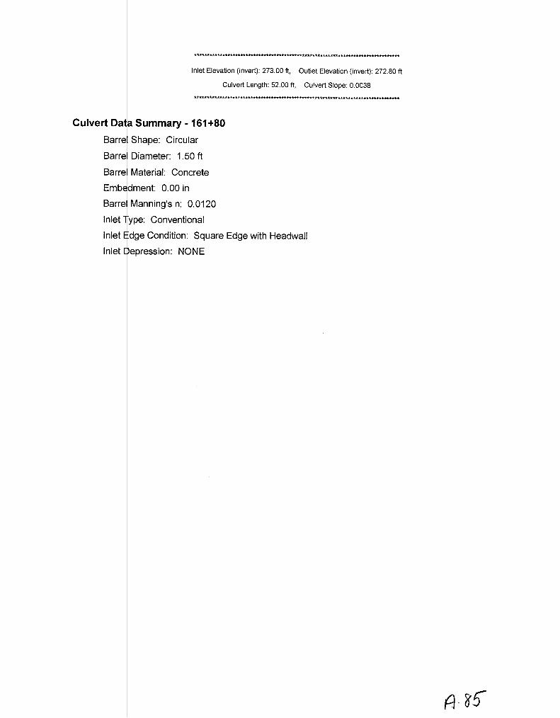
********************************************************************************
Inlet Elevation (invert): 273.00 ft, Outlet Elevation (invert): 272.80 ft
Culvert Length: 52.00 ft, Culvert Slope: 0.0038
********************************************************************************
Culvert Da a Summary -161+80
Barre Shape: Circular
Barre Diameter: 1.50 ft
Barre Material: Concrete
Emb dment: 0.00 in
Barre Manning's n: 0.0120
Inlet ype: Conventional
Inlet dge Condition: Square Edge with Headwall
Inlet epression: NONE

Water Surf ce Profile Plot for Culvert: 161 +80
278.0
277.5
277..0
276.5
~276.0 c -~ 275.5 .._, (\J
13> 275.0 w
274.5
274.0
273.5
273.0
Crossing- 161 +80, Design Discharge- 6.9 cfs Culvert- 161-'-80, Culvert Discharge- 6.9 cfs
\
\ \ J
\ +----------------~ \
~'[----------------~ '*JI;.,.,. ~------------::::::-:-_______ ::::!: _______ ~~-~~--! _________________ --./ : --- - -~ . '
-10 0 10 20 30 40 50 60 Statlon (ft}

Table 1- C ulvert Summary Table: 161+80 Total c I vert Headwater Inlet Control Outlet Flow Normal Critical Outlet Depth Tailwater Outlet Tailwater
Discharge Dis harge Elevation (ft) Depth (ft) Control Type Depth (ft) Depth (ft) (It) Depth (ft) Velocity Velocity (cfs) (pfs) Depth (ft) (ft/s) (ft/s)
/D 5.30 .30 274.42 1.347 1.419 2-M2c 0.970 0.886 0.887 0.885 4.873 1.255
5.55 .55 274.46 1.388 1.459 2-M2c 1.002 0.908 0.908 0.907 4.958 1.271
5.80 .80 274.50 1.430 1.499 3-M2! 1.035 0.927 0.928 0.928 5.052 1.287
6.05 .05 274.54 1.471 1.538 3-M2! 1.070 0.947 0.949 0.949 5.136 1.302
6.30 .30 274.58 1.513 1.577 3-M2! 1.107 0.967 0.969 0.969 5.220 1.317
6.55 .55 274.62 1.556 1.621 3-M2! 1.145 0.987 0.988 0.988 5.303 1.332
6.80 .80 274.66 1.600 1.662 3-M2! 1.183 1.007 1.008 1.008 5.386 ~.345
s-o 6.90 f.90 274.68 1.618 1.678 3-M2! 1.198 1.014 1.015 1.015 5.419 1.351
7.30 .30 274.74 1.690 1.741 2-M2c 1.293 1.046 1.046 1.045 5.546 1.372
7.55 .55 274.78 1.737 1.781 3-M2! 1.500 1.063 1.064 1.064 5.635 1.385
!!J c 7.80 .80 274.83 1.784 1.829 3-M2! 1.500 1.079 1.081 1.081 5.719 1.397
A -g7

********************************************************************************
Inlet Elevation (invert): 273.00 ft, Outlet Elevation (invert): 272.80 ft
Culvert Length: 52.00 ft, Culvert Slope: 0.0038
********************************************************************************
Culvert Da a Summary -161+80
Barr I Shape: Circular
I Diameter: 1.50 ft
Barr I Material: Concrete
Barr I Manning's n: 0.0120
ype: Conventional
dge Condition: Square Edge with Headwall
epression: NONE
A-88'

Water Surf ce Profile Plot for Culvert: 180+30
~rossing- 180+30, Design Discharge- 28.3 cfs Culvert- 180+3G, Culvert Discharge - 28.3 c:l:s
295.0
294.5
294.0 I f
293 .. 5 +--· -----------------
....... ---;; 293.0 0
~ 292.5 Q)
w 292.0 ...., .
. . -----------------X
291.5
291.0
290.5
-10 0 10 20 30 40 50 60 Station (ft}

Table 1 - Cl lvert Summary Table: 180+30 Total Cu I ert Headwater Inlet Control Outlet Flow Normal Critical Outlet Depth Tailwater Outlet Tailwater
Discharge Disc arge Elevation (ft) Depth (ft) Control Type Depth (ft) Depth (ft) (ft) Depth (ft) Velocity Velocity (cfs) (c s) Depth (ft) (ft/s) (ft/s)
I 6 15.40 15 40 292.52 1.966 0.947 1-S2n 1.218 1.320 1.219 1.187 6.481 2.413
17.36 1 .36 292.67 2.118 1.021 1-S2n 1.308 1.405 1.314 1.261 6.645 2.493
19.32 1L32 292.82 2.268 1.090 1-S2n 1.397 1.490 1.402 1.330 6.822 2.565
21.28 21.28 292.97 2.418 1.156 1-S2n 1.485 1.563 1.486 1.396 6.996 2.632 23.24 2 .24 293.12 2.572 1.218 5-S2n 1.577 1.635 1.579 1.458 7.119 2.694
25.20 2 .20 293.28 2.732 1.277 5-S2n 1.669 1.707 1.671 1.517 7.235 2.753
27.16 2 .16 ~~ ~ 1.334 5-S2n 1.763 1.774 1.763 1.574 7.339 2.808
5 0 28.30 2<.3o 1 293.64 '-3.002) 3.093 2-M2c 1.826 1.808 1.814 1.605 7.419 2.838
31.08 31.08 ~ 3.266 3.272 2-M2c 1.980 1.892 1.900 1.680 7.766 2.909
33.04 3 .04 ~.02 ..3-AfiP 3.422 2-M2c 2.141 1.951 1.956 1.730 8.028 2.956
(flJ 35.00 3~ .00 ,l"94.23 1 3.680 \ 3.571 2-M2c 2.500 2.007 2.010 1.779 8.273 3.001 ( ~~
-;- 60 boro,_d_c
I
A ·9D

********************************************************************************
Inlet Elevation (invert): 290.55 ft, Outlet Elevation (invert): 290.31 ft
Culvert Length: 46.00 ft, Culvert Slope: 0.0052
********************************************************************************
Culvert Oat Summary - 180+30
Barre Shape: Circular
Barre Diameter: 2.50 ft
Barre Material: Concrete
Emb dment: 0.00 in
Barre Manning's n: 0.0120
Inlet ype: Conventional
Inlet dge Condition: Square Edge with Headwall
Inlet epression: NONE

Table 2- De ~wnstream Channel Rating Curve {Crossing: 180+30)
Flow (cfs) Water Surface Depth (ft) Velocity (ft/s) Shear (psf) Froude Number Elev (ft)
I 0 15.40 291.50 1.19 2.41 0.44 0.47 17.36 291.57 1.26 2.49 0.47 0.47 19.32 291.64 1.33 2.57 0.50 0.48 21.28 291.71 1.40 2.63 0.52 0.48 23.24 291.77 1.46 2.69 0.55 0.48 25.20 291.83 1.52 2.75 0.57 0.48 27.16 291.88 1.57 2.81 0.59 0.48
0 028.30 291.92 1.61 2.84 0.60 0.49 31.08 291.99 1.68 2.91 0.63 0.49 33.04 292.04 1.73 2.96 0.65 0.49
, rn 35.oo 292.09 1.78 3.00 0.67 0.49
A

Tailwater C annel Data - 180+30
Tailw ter Channel Option: Trapezoidal Channel
Botto Width: 3.00 ft
Side lope (H:V): 2.00 (_: 1)
Chan el Slope: 0.0060
Chan el Manning's n: 0.0400
Chan ellnvert Elevation: 290.31 ft

Water Surf ce Profile Plot for Culvert: 180+30
~rossing- 180+30, Design Discharge- 14.2 cfs
295.0
294.5
294.0
~293.5 ...... -
Culvert- 18Jr3G, Culvert Discharge- 142 cfs
~293.0 0 +-----------------
~ 292.5 <D
w 292.0 ·-········ ......... ~""~~ 0000'00' ~~~-A. ---~¥~~~A
291.5
291.0
290.5
-10 0 10 20 30 40 Station (ft)
50

Table 1 - Cl lvert Summary Table: 180+30 Total Cui ert Headwater Inlet Control Outlet Flow Normal Critical Outlet Depth Tailwater Outlet Tailwater
Discharge Disc arge Elevation (It) Depth (It) Control Type Depth (It) Depth (It) (ft) Depth (It) Velocity Velocity (cfs) (c s) Depth (It) (ft/s) (Ills)
(0 7.70 7. 0 292.00 1.448 0.590 1-S2n 0.919 0.985 0.924 0.830 5.420 1.992
8.68 8.~8 292.11 1.558 0.644 1-S2n 0.987 1.047 0.987 0.884 5.616 ~.061
9.66 9.~6 292.21 1.665 0.694 1-S2n 1.052 1.107 1.056 0.934 5.743 2.123
10.64 10 64 292.32 1.769 0.743 1-S2n 1.116 1.166 1.120 0.983 5.883 2.181
11.62 11 62 292.42 1.874 0.788 1-S2n 1.181 1.222 1.181 1.028 6.020 2.234
12.60 12 60 292.53 1.980 0.832 1-S2n 1.247 1.272 1.252 1.072 6.095 2.285
13.58 13 58 292.64 2.089 0.874 5-S2n 1.313 1.323 1.316 1.114 6.206 2.332
so 14.20 14 20 I,. 292.82 ,./ ? 1RO"'- 2.270 2-M2c 1.356 1.354 1.357 1.139 6.256 2.361
15.54 15 54 292.94 2.319 2.392 2-M2c 1.455 1.419 1.421 1.193 6.510 2.419
16.52 16 52 mQ4 ~43 2.489 2-M2c 1.534 1.460 1.465 1.230 6.698 2.459
( 17.50 17 50 ~293.13) u 2.573) 2.580 2-M2c 1.621 1.502 1.508 1.266 6.889 2.498 -
tt9b

********************************************************************************
Inlet Elevation (invert): 290.55 ft, Outlet Elevation (invert): 290.31 ft
Culvert Length: 46.00 ft, Culvert Slope: 0.0052
********************************************************************************
Culvert Oat Summary - 180+30
Barre Shape: Circular
Barre Diameter: 2.00 ft
Barre Material: Concrete
Emb dment: 0.00 in
Barre Manning's n: 0.0120
Inlet ype: Conventional
Inlet dge Condition: Square Edge with Headwall
Inlet epression: NONE

Water Surfa e Profile Plot for Culvert: 190+12
. .rossing - 190+ 12, Design Discharge - 3 3 . 6 cfs Culvert- 19Ch-12, Culvert Discharge- 33_6 cfs
c 300
303
\ 302
I ----------------------!
301
0 ...... (iJ
iD 299 -w
298 ------------------)(:
297
296
-20 0 20 40 60 80 Station {ft)

Table 1- Cu !vert Summary Table: 190+12 Total Cu I ~rt Headwater Inlet Control Outlet Flow Normal Critical Outlet Depth Tailwater Outlet Tailwater
Discharge Disc h~rge Elevation (ft} Depth (fl} Control Type Depth (ft} Depth (ft} (ft} Depth (ft) Velocity Velocity (cis} (cf } Depth (ft} (fils} (fils}
18.40 18. 0 298.78 2.187 0.0* 1-S2n 1.033 1.450 1.089 1.068 8.956 3.356
20.71 20. 1 298.95 2.364 0.0* 1-S2n 1.102 1.543 1.168 1.134 9.206 3.466
23.02 23.02 299.13 2.545 o.o· 5-S2n 1.171 1.627 1.243 1.197 9.444 3.567
25.33 25 33 299.32 2.733 0.0* 5-S2n 1.240 1.712 1.318 1.256 9.654 3.660
27.64 27 64 299.52 2.933 0.0* 5-S2n 1.306 1.789 1.314 1.312 10.576 3.747
29.95 29 95 299.74 3.146 0.515 5-S2n 1.372 1.858 1.381 1.365 10.778 3.828
32.26 32 26 299.97 3.375 0.566 5-S2n 1.437 1.928 1.446 1.416 10.969 3.905
33.60 33 60 300.11. 3.51ID 0.595 5-S2n 1.475 1.968 1.568 1.445 10.379 3.947
36.88 36 88 300.48 3.887 0.663 5-S2n 1.571 2.047 1.672 1.513 10.585 4.045
39.19 3919 300.76 ~ 0.708 5-S2n 1.639 2.096 1.734 1.558 10.793 4.111
ttJ() 41.50 41 50 301.07 f 4.476) 0.753 5-S2n 1.707 2.144 1.804 1.603 10.957 4.173
A- qo

* theo etical depth is impractical. Depth reported is corrected.

********************************************************************************
Inlet Elevation (invert): 296.59 ft, Outlet Elevation (invert): 295.74 ft
Culvert Length: 64.01 ft, Culvert Slope: 0.0133
********************************************************************************
Culvert Da Summary -190+12
Barrel Shape: Circular
Barrel Diameter: 2.50 ft
Barrel Material: Concrete
Embe ment: 0.00 in
Barrel Manning's n: 0.0120
Inlet ype: Conventional
Inlet dge Condition: Square Edge with Headwall
Inlet epression: NONE

303
302
301
,..........
~300 c 0
:+:; C\1 > Q)
w 299
298
297
'-=? 296 ...__ C::> -
+········································--······················
-20 -10
Crossing - 190+ 12, Design Discharge - 41.8 cfs Culvert- 190+ 12, Culvett Discharge- 41.8 cfs
&----~-~--~----~---------~-----------------------~~~-----"" / \ ~ \ / \
I \ i \
j \ ' \ \ I \
f ' .• ' .. \
I '\ I \ ! \
I \ j \
;I \ ( \
I \ j \
! \ I \ ! I / :
I '\ I \ . \
\
0 10 20 30 40 50 60 Station (ft)
I
--------------~--~~~-0
70 80

Table 1 -Culvert Summary Table: 190+12 Total
Discharge (cfs)
Culvert Disch rge
(cf )
Headwater Inlet Control Elevation (ft) Depth (ft}
Outlet Control
Depth {ft)
Flow Type
Normal Depth (ft)
Critical Depth (ft)
Outlet Depth (ft)
Tailwater Depth (ft)
()(]Uet Velocity
(ft/s)
Tailwater Velocity
(ft/s)
jL) r--2~3~.o~o~~~2~3i.~o--+-~2~9~9~.1~3--t-~2~·=54~3~~--o~.~o·~-+-~~2~n-+--~1~.1~71~~--1~·=62~7~~~1~.2~4=3--+-~1~.1~96~~--9~.~44~2~~~3~.5~6~6~ 25.86 25. 6 299.37 2.778 0.0* 5-S2n 1.256 1.732 1.257 1.269 10.467 3.680
28.72 28. 2 299.62 3.030 0.0* 5-S2n 1.337 1.821 1.345 1.337 10.672 3.785
31.58 31. 8 299.90 3.306 0.552 5-S2n 1.418 1.907 1.421 1.402 10.967 3.883
34.44 34. 4 300.20 3.607 0.613 5-S2n 1.499 1.993 1.598 1.463 10.407 3.973
37.30 37.30 300.53 3.937 0.671 5-S2n 1.583 2.056 1.681 1.521 10.641 4.058
40.16 40.16 300.89 4.~ 0.727 5-S2n 1.668 2.116 1.760 1.577 10.872 4.138 en~~~~~~~~~~--+-~~~~~~~~~~~~~~ 0 V 41.80 41.80 301.11 .. er 4.5!,Z.) 0.758 5-S2n 1.716 2.151 1.814 1.608 10.978 4.182
45.88 45.88 301.70 5.107 0.832 5-S2n 1.851 2.237 1.937 1.682 11.263 4.285
/ /\r\~-4~8~.7~4~~~4~8f..~4--+--3~0~2~.1~5~~~~·~~~~0~.8~8~2--+-5~-~S2~n~--~1~.9~51~~~2~.~29~7~~~2~.0~2~5--+-~1~.7~32~~~1~1~.4~3~2~~-4~.3~5~3--i vt.l 51.60 51 60 302.63( 6.036 0.930 5-S2n 2.080 2.357 2.086 1.780 11.826 4.419
I D
/{)() (j.J
,4- 161--

* theor tical depth is impractical. Depth reported is corrected.
A- JoS

********************************************************************************
Inlet Elevation (invert): 296.59 ft, Outlet Elevation (invert): 295.74 ft
Culvert Length: 64.01 ft, Culvert Slope: 0.0133
********************************************************************************

Culvert Pe rmance Curve Plot: 190+12
302
§ 301 ...... (ij
> (1)
w 300 '--(!)
-I-' (ij
$299 u (ij (1)
I 298
[I]
Perfonnance Curve Culve.rt 19~ 12
[I] Inlet Contro~ Erev Outlet Control Elev
·----- ---- ·--------- -.&:-------- -·----·-----·· ---- ---- -·---------·---------..
297 ~~~~~~----~------~----~----~--~ 25 30 35 40 45 50 Total Discharge (cfs)

-45
-45
-45
~ ........_ c:::,
€)"
-40
-40
-40
-35 -30 -25
-35 -30 -25
-35 -30 -25
Dft= ~ f.o /J-lLlO Q &0::--S8o ~ C-PS (5.( I (Jl) ::. '1/ .f CP. S
S moon-J d£_t
-20 -/5
-20 -15
-20 -15
-/0 -5
.;~q.~
jfj~-~
0
STAl22.3•71.74.l27.!2' RT to STAl223•7B.22.. 28;51( LT;
· .JNstALL6C! X 156.00'; ; . . CUL~ERTPJ/f'l:j OPT. 'II! . 1£MBf=.DD£D 15';~~- L
.. .t ...
-10 -5 0
223+74.90
-10 -5 0
5
5
5
ctv?Prfl;'
2fq.,f zqoJ 5
/0 15
10 15
/0 15
20
20
20
/.6'~d wJ/I,Ayn,o~ (/~
At().dwa~
25 30 35 40
25 30 35 40
25 30 35 40
45 50
45 50
45 50

Table 1-St mmary of Culvert Flows at Crossing: 223+75 Headwater Ele ation Total Discharge (cfs) 223+ 75 smooth 2' Roadway Discharge Iterations
(ft) embed Discharge (cfs) (cfs)
288.59 32.60 32.60 0.00 1 288.75 36.52 36.52 0.00 1 288.91 40.44 40.44 0.00 1 289.06 44.36 44.36 0.00 1 289.22 48.28 48.28 0.00 1
289.36 52.20 52.20 0.00 1 289.52 56.12 56.12 0.00 1 289.61 58.60 58.60 0.00 1 289.81 63.96 63.96 0.00 1 290.00 67.88 67.88 0.00 1 290.23 71.80 71.80 0.00 1 294.29 130.49 130.49 0.00 Overtopping

Rating Cu e Plot for Crossing: 223+75
·_,__..
290.2
290.0
~289.8 c 0
~ 289.6 > G)
w 289.4 '-G)
~ 289.2 "0 ro
:!£ 289.0
288.8
288J3
35 40
Total Rating Curve Crossing: 223+ 75
45 50 55 60 Total Discharge (cfs)
65 70

Table 2 - CLivert Summary Table: 223+75 smooth 2' embed Total
Discharge (cfs)
32.60
36.52
40.44
44.36
48.28
52.20
56.12
58.60
63.96
67.88
71.80
Cui ert Headwater Inlet Control Disci arge Elevation (ft) Depth (ft)
(c s)
32 60 288.59 1.952
36 52 288.75 2.107
4044 288.91 2.262
44 36 289.06 2.415
48 28 289.22 2.565
52 20 289.36 2.715
5612 289.52 2.864
58 60 289.61 2.959
63 96 289.81 3.171
6 .88 290.00 3.399
71.80 290.23 3.626
Outlet Control
Depth (ft)
1.989
2.151
2.306
2.463
2.617
2.764
2.916
3.012
3.213
3.365 3.518
Flow Type
3-M2t
3-M2t
3-M2t
3-M2t
3-M2t
3-M2t
3-M2!
3-M2t
3-M2t 3-M2!
3-M2t
Normal Depth (ft)
1.350
1.457
1.562
1.665
1.769
1.875
1.981
2.049
2.206
2.325
2.460
Critical Depth (ft)
1.093
1.182
1.261
1.338
1.415
1.492
1.561
1.604
1.697
1.765
1.829
Outlet Depth (ft)
1.260
1.339
1.413
1.483
1.551
1.615
1.676
1.714
1.793
1.848
1.902
Tailwater Depth (ft)
1.260
1.339
1.413
1.483
1.551
1.615
1.676
1.714
1.793 1.848
1.902
Outlet Velocity
(f!/s)
5.256
5.555
5.843
6.122
6.394
6.659
6.918
7.079
7.421
7.659 7.924
Tailwater Velocity
(ft/s)
3.440
3.553
3.657
3.754
3.844
3.928
4.008
4.056
4.155 4.222
4.288

********************************************************************************
Inlet Elevation (invert): 286.60 ft, Outlet Elevation (invert): 286.05 ft
Culvert Length: 56.00 ft, Culvert Slope: 0.0098
********************************************************************************
rr ,,o

Culvert Per ormance Curve Plot: 223+75 smooth 2' embed
~
-+-'
290..2
290.0
~-289.8 0
w 289.6 > G)
w 289.4 '-a>
-ro 289.2 $
m 289_0 I
288.8
288.6
35
Perfom1ance Curve Culvert: 223+ 75 smooth 2' embed
00 [i] Inlet Control Elev Outtet Control Elev
40 45 50 55 60 Total Discharge (cfs)
65 70
A- Ill

Water Surf ce Profile Plot for Culvert: 223+75 smooth 2' embed
_,rossing- 223+ 75, Design Discharge - 58.6 cfs Culvert- 223+ 75 smooth 2' embed, Culvert Discharge - 58.6 cfs
-~ _,__,
294
293
292
291 ~-290 c 0
~ 289 >
\ I +----------------rL-----~ - -
0) 288 w I ----· ----- --------·- --------- ---· ---------- --·.- --------.---- .. --·.-. ---, ________________ ;)(
287
286
285
284
0 20 40 Station (ft)
Site Data- 223+75 smooth 2' embed
ata Option: Culvert Invert Data
Inlet tation: 0.00 ft
Inlet levation: 284.60 ft
Out! t Station: 56.00 ft
Out! t Elevation: 284.05 ft
Culvert D ta Summary- 223+75 smooth 2' embed
Barr I Shape: Circular
Barr I Diameter: 5.00 ft
Barr I Material: Concrete
Barr I Manning's n: 0.0120 (top and sides)
Man ing's n: 0.0350 (bottom)
Inlet Type: Conventional
Inlet Edge Condition: Mitered to Conform to Slope
Inlet Depression: NONE
60

Table 3- De wnstream Channel Rating Curve (Crossing: 223+75)
Flow (cfs) Water Surface Depth (ft) Velocity (fils) Shear (psf) Froude Number Elev (ft)
32.60 287.31 1.26 3.44 0.79 0.62 36.52 287.39 1.34 3.55 0.84 0.63 40.44 287.46 1.41 3.66 0.88 0.63 44.36 287.53 1.48 3.75 0.93 0.64 48.28 287.60 1.55 3.84 0.97 0.64 52.20 287.66 1.61 3.93 1.01 0.64 56.12 287.73 1.68 4.01 1.05 0.65 58.60 287.76 1.71 4.06 1.07 0.65 63.96 287.84 1.79 4.15 1.12 0.65 67.88 287.90 1.85 4.22 1.15 0.65 71.80 287.95 1.90 4.29 1.19 0.66
ft /13

Tailwater C annel Data- 223+75
Tailw ter Channel Option: Trapezoidal Channel
Botto Width: 5.00 ft
Side lope (H:V): 2.00 (_:1)
Chan el Slope: 0.0100
Chan el Manning's n: 0.0400
Chan ellnvert Elevation: 286.05 ft
Roadway D ta for Crossing: 223+75
ay Profile Shape: Constant Roadway Elevation
ength: 50.00 ft
levation: 294.29 ft
ay Surface: Paved
ay Top Width: 28.00 ft

Water Surfa e Profile Plot for Culvert: 223+75
294
293
292
~291 c 0
:;:::; 290 (1)
> (jj
w 289
288
287
286
~rossing- 223+75, Design Discharge- 58.4 cfs 1 / Culvert- 223-:-75, Culvert Discharge- 58.4 cfs j .£ J~rw
-10 0 10 20 30 Station {ft)
40 50 60
A- J ,s-
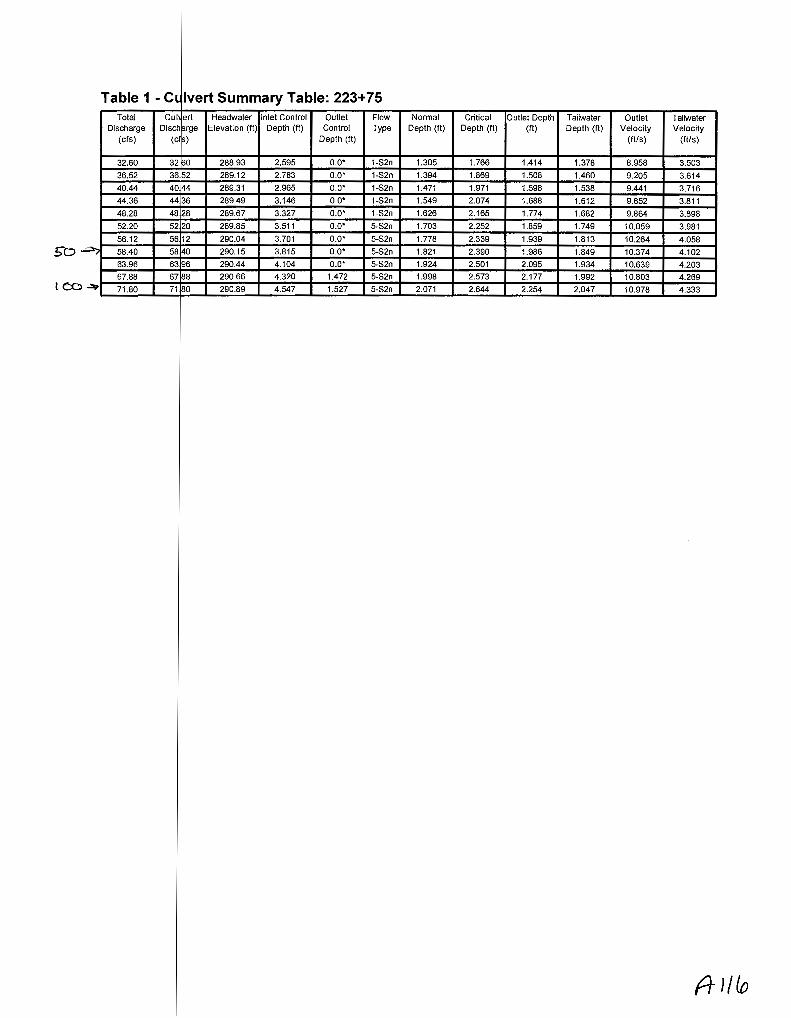
Table 1 - CL lvert Summary Table: 223+75 Total Cui ert Headwater Inlet Control Outlet Flow Normal Critical Outlet Depth Tailwater Outlet Tailwater
Discharge Disc harge Elevation (ft) Depth (ft) Control Type Depth (ft) Depth (ft) (ft) Depth (ft) Velocity Velocity (cfs) (c s) Depth (ft) (ft/s) (ft/s)
32.60 32.60 288.93 2.595 o.o· 1-S2n 1.305 1.766 1.414 1.378 8.958 3.503
36.52 36 52 289.12 2.783 o.o· 1-S2n 1.394 1.869 1.508 1.460 9.205 3.614
40.44 40 4 289.31 2.965 o.o· 1-S2n 1.471 1.971 1.598 1.538 9.441 3.716
44.36 44 36 289.49 3.146 o.o· 1-S2n 1.549 2.074 1.688 1.612 9.652 3.811
48.28 48 28 289.67 3.327 o.o· 1-S2n 1.626 2.165 1.774 1.682 9.864 3.898
52.20 52 20 289.85 3.511 o.o· 5-S2n 1.703 2.252 1.859 1.749 10.059 3.981
56.12 5612 290.04 3.701 o.o· 5-S2n 1.778 2.339 1.939 1.813 10.264 4.058
50 -=;; 58.40 58 40 290.15 3.815 o.o· 5-S2n 1.821 2.390 1.986 1.849 10.374 4.102'
63.96 63 96 290.44 4.104 o.o• 5-S2n 1.924 2.501 2.095 1.934 10.639 4.203
67.88 67 88 290.66 4.320 1.472 5-S2n 1.998 2.573 2.177 1.992 10.803 4.269 ~ 71.80 71 80 290.89 4.547 1.527 5-S2n 2.071 2.644 2.254 2.047 10.978 4.333
A }/(o

* theo etical depth is impractical. Depth reported is corrected.
(t J/1

********************************************************************************
Inlet Elevation (invert): 286.34 ft, Outlet Elevation (invert): 285.82 ft
Culvert Length: 52.00 ft, Culvert Slope: 0.0100
********************************************************************************
Culvert Oat Summary- 223+75
Barrel Shape: Circular
Barrel Diameter: 3.50 ft
Barrel Material: Concrete
Embe ment: 0.00 in
Inlet T pe: Conventional
Inlet dge Condition: Square Edge with Headwall
Inlet epression: NONE

Water Surfa e Profile Plot for Culvert: 233+26
297
296
295
294 .~ ........ ...... . ._,., 29::1 c. ~
0 :;:::; (1J 292 > (j}
w 291
290
289
288
:rossing- 233 i 26, Design Discharge- 80.0 cfs Culvert- 233+26, Culvert Discharge- 80.0 d's
~--------------
I I
\ : ·~-----------------)(
-10 0 10 20 30 40 50 60 70 Station (ft)
ft /19

Table 1 -Culvert Summary Table: 233+26 Total
Discharge (cfs)
Cui' ert Headwater Inlet Control Disch rge Elevation (fl) Depth (fl)
(cf )
Outlet Control
Depth (fl)
Flow Type
Normal Depth (fl)
Critical Depth (fl)
Outlet Depth (fl)
Tailwater Depth (ft)
Outlet Velocity
(fils)
Tailwater Velocity
(fl/s)
45.00 45. 0 291.83 2.932 0.0* 1-S2n 1.284 2.007 1.461 2.239 10.808 5.024
50.30 50. o 292.04 3.141 0.0* 1-S2n 1.360 2.121 1.561 2.438 11.070 5.158
55.60 55. o 292.24 3.343 o.O* 1-S2n 1.435 2.234 1.657 2.634 11.297 5.276
60.90 60 ~0 292.44 3.543 0.0* 1-S2n 1.510 2.348 1.747 2.828 11.537 5.383
66.20 66 20 292.64 3.743 0.0* 1-S2n 1.586 2.452 1.835 3.020 11.760 5.480
71.50 71 50 292.85 3.946 0.0* 1-S2n 1.653 2.549 1.922 3.211 11.973 5.568
76.80 76 80 293.05 4.154 0.0* 5-S2n 1.718 2.645 2.007 3.399 12.171 5.648
80.00 80 00 293.18 4.283 0.0* 5-S2n 1.757 2.703 2.057 3.513 12.291 5.694
87.40 87 40 293.49 4.594 0.0* 5-S2n 1.848 2.830 2.170 3.773 12.557 5.791 I~ ~~-9~2~.7~0~~~9~2~7~0--+-~2~9~3~.7~3--~-4~.~82~9~~--o~.~o.~-+~5~-~S2~n-+--~1.~9~13~~--2~.~90~9~~~2~.2~4~8--+-~3~.9~59~~~1~2~.7~5~1~~~5~.8~5~4~
98.00 98 00 293.98 5.076 4.877 4-FFf 1.979 2.988 1.979 4.143 15.810 5.913

********************************************************************************
Inlet Elevation (invert): 288.90 ft, Outlet Elevation (invert): 288.00 ft
Culvert Length: 55.01 ft, Culvert Slope: 0.0164
********************************************************************************
Culvert Oat Summary - 233+26
Barrel Shape: Circular
Barrel Diameter: 4.00 ft
Barrel Material: Concrete
Embe ment: 0.00 in
Barrel Manning's n: 0.0120
Inlet pe: Conventional
Inlet dge Condition: Square Edge with Headwall
Inlet epression: NONE
f+ I 'Z/

Water Surf ce Profile Plot for Culvert: 249+1 0
~rossing - 24 9+ 10, Design Discharge - 1 7. 0 cfs Culvert - 249-'-10, Culvert Discharge - 17 J} d's.
331.5--n------------------------,
331.0
330.5
330.0
~329.5 ....... ~
c 329.0 0
::;:::; g; 328.5 (1)
w 328.0
327.5
327.0
326.5
326.0
-10
. '-----------------)(
0 10 20 30 40 50 60 Station (ft)
A 121

Table 1- C u vert Summary Table: 239+57 Total Cui v rt Headwater Inlet Control Outlet Flow Normal Critical Outlet Depth Tailwater Outlet Tailwater
Discharge Disc h rge Elevation (ft) Depth (ft) Control Type Depth (ft) Depth (ft) (ft) Depth (ft) Velocity Velocity (cfs) (cf ) Depth (ft) (ft/s) (ftls)
5.10 5.10 304.45 1.310 0.196 1-S2n 0.714 0.867 0.716 0.686 6.122 2.203
5.32 5. 2 304.49 1.346 0.211 1-S2n 0.732 0.888 0.733 0.701 6.203 2.229
5.54 5. 4 304.52 1.382 0.226 1-S2n 0.750 0.907 0.751 0.716 6.261 2.254
5.76 5. 6 304.56 1.419 0.241 1-S2n 0.768 0.924 0.768 0.731 6.325 2.278
5.98 5. 8 304.60 1.455 0.255 1-S2n 0.785 0.942 0.785 0.745 6.389 2.301
6.20 6. 0 304.63 1.492 0.269 1-S2n 0.802 0.959 0.804 0.759 6.430 2.324
6.42 6. 2 304.67 1.530 0.282 5-S2n 0.820 0.976 0.821 0.772 6.484 2.346
6.50 6. 0 304.68 1.543 0.287 5-S2n 0.826 0.983 0.828 0.777 6.503 2.354
6.86 6. 6 304.75 1.606 0.309 5-S2n 0.855 1.011 0.856 0.799 6.584 2.388
7.08 7. 8 304.79 1.646 0.321 5-S2n 0.872 1.029 0.873 0.811 6.640 2.409
7.30 7. 0 304.83 1.686 0.334 5-S2n 0.889 1.046 0.890 0.824 6.684 2.429
AI

********************************************************************************
Inlet Elevation (invert): 303.14 ft, Outlet Elevation (invert): 302.65 ft
Culvert Length: 52.00 ft, Culvert Slope: 0.0094
********************************************************************************
Culvert Oat Summary - 239+57
Barrel Shape: Circular
Barrel Diameter: 1.50 ft
Barrel Material: Concrete
Embe ment: 0.00 in
Inlet T pe: Conventional
Inlet dge Condition: Square Edge with Headwall
Inlet epression: NONE

Table 1- C ulvert Summary Table: 249+1 0 Total Cui v~rt Headwater Inlet Control Outlet Flow Normal Critical Outlet Depth Tailwater Outlet Tailwater
Discharge Disch rge Elevation (ft) Depth (ft) Control Type Depth (ft) Depth (ft) (ft) Depth (ft) Velocity Velocity (cfs) (cf) Depth (ft) (ft/s) (ft/s)
9.50 9. 0 328.09 1.649 1.753 2-M2c 1.144 1.097 1.101 1.029 5.360 1.825
10.65 10. 5 328.21 1.772 1.873 2-M2c 1.233 1.167 1.169 1.091 5.583 1.883
11.80 11. 0 328.33 1.895 1.990 2-M2c 1.325 1.231 1.233 1.150 5.803 1.937
12.95 12.~5 328.45 2.020 2.107 2-M2c 1.419 1.290 1.294 1.205 6.021 1.986
14.10 14. 0 328.57 2.149 2.228 2-M2c 1.526 1.349 1.352 1.258 6.237 2.032
15.25 15.~5 328.69 2.285 2.346 2-M2c 1.654 1.407 1.408 1.308 6.455 2.075
16.40 16. 0 328.81 2.429 2.471 2-M2c 2.000 1.455 1.460 1.356 6.675 2.116
17.00 17.00 328.88 2.507 2.538 2-M2c 2.000 1.480 1.486 1.381 6.791 2.137
18.70 18. 0 329.08 2.743 2.724 2-M2c 2.000 1.552 1.557 1.448 7.139 2.191
19.85 19.85 329.26 2.916 2.882 2-M2c 2.000 1.600 1.601 1.491 7.364 2.226
21.00 21 00 329.44 3.101 3.036 2-M2c 2.000 1.634 1.642 1.532 7.590 2.260
A J

Site Data - 2 9+1 0
Inlet Elevation (invert): 326.34 ft, Outlet Elevation (invert): 326.14 ft
Culvert Length: 52.00 ft, Culvert Slope: 0.0038
SiteD ta Option: Culvert Invert Data
InletS ation: 0.00 ft
Inlet E evation: 326.34 ft
tation: 52.00 ft
Outlet levation: 326.14 ft
r of Barrels: 1
Culvert Oat Summary - 249+1 0
hape: Circular
iameter: 2.00 ft
aterial: Concrete
anning's n: 0.0120
Inlet T pe: Conventional
Inlet E ge Condition: Square Edge with Headwall
Inlet D pression: NONE
Roadway D ta for Crossing: 249+10
Road ay Profile Shape: Constant Roadway Elevation
Crest ength: 50.00 ft
Crest levation: 331.24 ft
Road ay Surface: Paved
Road ay Top Width: 32.00 ft

Water Surfac Profile Plot for Culvert: 262+25
C ossing- 262+25, Design Discharge- 13.7 cfs Culvert- 262-:-25, Culvert Discharge -13.7 cfs
350 +- -----------------~-===========~r::::::o:~r.--.
300
250
§ 200 +-' ro > ~ 150
100
50
Site Data Option: Culvert Invert Data
Inlet Stati n: 0.00 ft
Outlet St tion: 47.00 ft
Outlet Ele ation: 346.08 ft
Culvert Data S mmary - 262+25
Barrel Sh pe: Circular
Barrel Dia eter: 2.00 ft
Barrel Ma ning's n: 0.0120
Inlet Type: Conventional
Inlet Edge Condition: Square Edge with Headwall
Inlet Depr ssion: NONE
60

Table 1- Sum ~ary of Culvert Flows at Crossing: 262+25 Headwater Elevatipn Total Discharge (cfs) 262+25 Discharge Roadway Discharge Iterations
(ft) (cfs) (cfs)
347.83 7.30 7.30 0.00 1 347.94 8.27 8.27 0.00 1
348.05 9.24 9.24 0.00 1
348.15 10.21 10.21 0.00 1
348.25 11.18 11.18 0.00 1
348.36 12.15 12.15 0.00 1
348.47 13.12 13.12 0.00 1
348.53 13.70 13.70 0.00 1
348.69 15.06 15.06 0.00 1
348.81 16.03 16.03 0.00 1
348.93 17.00 17.00 0.00 1
351.76 31.53 31.53 0.00 Overtopping

Rating Curve Plot for Crossing: 262+25
348_8
§ 348_6 ....... ro > G)
w 348_4 ,_ !}) _,_, ro :;;>
-5 348_2 ro Q)
I
348_0
8
Total Rating Curve Crossing: 262+ 25
10 12 14 Total Discharge (cfs)
16

Table 2 - Culv ~rt Summary Table: 262+25 Total Culvert Headwater Inlet Control Outlet Flow Normal Critical Outlet Depth Tailwater Outlet Tailwater
Discharge DischargE . Elevation (ft) Depth (ft) Control Type Depth (ft) Depth (ft) (ft) Depth (ft) Velocity Velocity (cfs) (cfs) Depth {ft) (ft/s) (ft/s)
7.30 7.30 347.83 1.399 0.0* 1-S2n 0.809 0.956 0.809 0.561 6.128 3.158
8.27 8.27 347.94 1.510 0.0* 1-S2n 0.865 1.023 0.872 0.600 6.286 3.278
9.24 9.24 348.05 1.617 0.0* 1-S2n 0.922 1.081 0.924 0.638 6.504 3.386
10.21 10.21 348.15 1.721 0.0* 1-S2n 0.978 1.140 0.979 0.674 6.674 3.487
11.18 11.18 348.25 1.825 0.0* 1-S2n 1.032 1.199 1.032 0.707 6.839 3.580
12.15 12.15 348.36 1.929 0.0* 1-S2n 1.085 1.249 1.088 0.740 6.959 3.668
13.12 13.12 348.47 2.035 0.0* 5-S2n 1.139 1.299 1.143 0.771 7.074 3.749
13.70 13.70 348.53 2.100 0.0* 5-S2n 1.170 1.329 1.172 0.788 7.165 3.796
15.06 15.06 348.69 2.259 0.0* 5-S2n 1.247 1.399 1.247 0.829 7.306 3.899
16.03 16.03 348.81 2.378 0.0* 5-S2n 1.302 1.440 1.305 0.857 7.396 3.969
17.00 17.00 348.93 2.503 0.0* 5-S2n 1.358 1.480 1.359 0.884 7.483 4.035
rt ~~ r

* theoreti al depth is impractical. Depth reported is corrected.
R 1.30
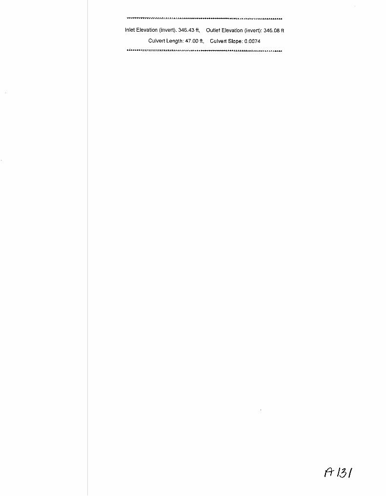
********************************************************************************
Inlet Elevation (invert): 346.43 ft, Outlet Elevation (invert): 346.08 ft
Culvert Length: 47.00 ft, Culvert Slope: 0.0074
********************************************************************************
A' 131

Culvert Perfo mance Curve Plot: 262+25
348_8
6 348J3 +-' m > Q)
w 348_4 '-{!)
+-' m $ 348.2
""0 m Q)
I 348_0
8
Perforrnance Curve Culvert: 262-'-25
[I] [I] Inlet Control Elev Outlet Control E~ev
10 12 14 16 Total Discharge (cfs)
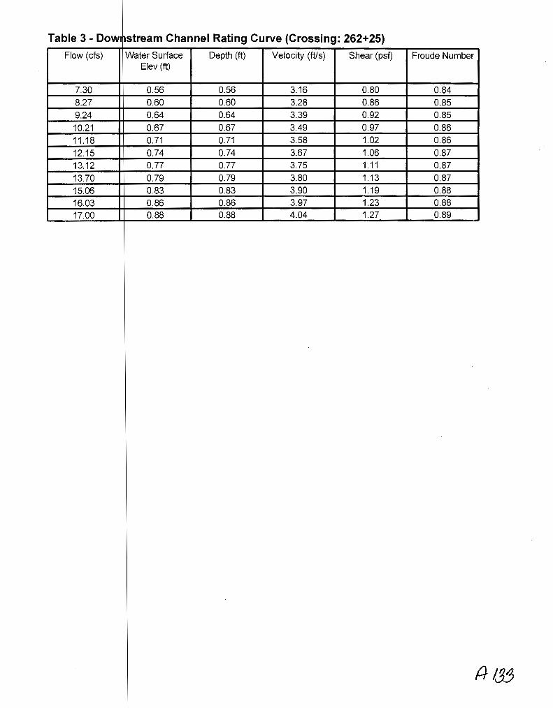
Table 3 - Dow• ~stream Channel Rating Curve (Crossing: 262+25)
Flow (cfs) Water Surface Depth (ft) Velocity (ftls) Shear (psf) Froude Number Elev (ft)
7.30 0.56 0.56 3.16 0.80 0.84 8.27 0.60 0.60 3.28 0.86 0.85 9.24 0.64 0.64 3.39 0.92 0.85
10.21 0.67 0.67 3.49 0.97 0.86
11.18 0.71 0.71 3.58 1.02 0.86
12.15 0.74 0.74 3.67 1.06 0.87
13.12 0.77 0.77 3.75 1.11 0.87
13.70 0.79 0.79 3.80 1.13 0.87
15.06 0.83 0.83 3.90 1.19 0.88
16.03 0.86 0.86 3.97 1.23 0.88 17.00 0.88 0.88 4.04 1.27 0.89

Tailwater Cha nel Data - 262+25
Tailwate Channel Option: Trapezoidal Channel
Bottom idth: 3.00 ft
Side Slo e (H:V): 2.00 (_:1)
Channel lope: 0.0230
Channel anning's n: 0.0400
Channel nvert Elevation: 0.00 ft
Roadway Dat for Crossing: 262+25
Roadwa Profile Shape: Constant Roadway Elevation
Crest Le gth: 50.00 ft
Surface: Paved
Top Width: 28.00 ft

HY-8 Analysis Results
Crossing Sum mary Table
Culvert C rossing: 262+25
Headwater Elevatiof1 ifotal Discharge (cfs) 262+25 Discharge Roadway Discharge Iterations (ft) (cfs) (cfs)
347.83 7.30 7.30 0.00 1
347.94 8.27 8.27 0.00 1
348.05 9.24 9.24 0.00 1
348.15 10.21 10.21 0.00 1
348.25 11.18 11.18 0.00 1
348.36 12.15 12.15 0.00 1
348.47 13.12 13.12 0.00 1
348.53 13.70 13.70 0.00 1
348.69 15.06 15.06 0.00 1
348.81 16.03 16.03 0.00 1
348.93 17.00 17.00 0.00 1
351.76 31.53 31.53 0.00 Overtopping
p

Water Surf ce Profile Plot for Culvert~
600
550
c -~ 500 ......, ro > Q)
w 450
400
350
.rossing- 266:08, Design Discharge- 13.6 cfs Culvert- 266+08, Culvert Discharge- 13.6 cfs
-10 0 10 20 30 40 50 60 Station (ft)
70

Table 1 - Ct lvert Summary Table: 266+08 Total Cui ert Headwater Inlet Control Outlet Flow Normal Critical Outlet Depth Tailwater Outlet Tailwater
Discharge Disc~ arge Elevation (It) Depth (It) Control Type Depth (It) Depth (It) (It) Depth (It) Velocity Velocity (cfs) (c s) Depth (It) (ft/s) \ftls)
[{) 7.20 7. 0 358.08 1.386 0.027 1-S2n 0.759 0.949 0.764 0.517 6.520 3.451 8.18 8. 8 358.19 1.499 0.065 1-S2n 0.816 1.017 0.817 0.555 6.783 3.587 9.16 9. 6 358.30 1.607 0.101 1-S2n 0.867 1.077 0.870 0.591 6.983 3.710 10.14 1014 358.40 1.712 0.134 1-S2n 0.918 1.136 0.926 0.624 7.121 3.823 11.12 1112 358.51 1.817 0.166 1-S2n 0.970 1.196 0.975 0.656 7.314 3.928
12.10 1210 358.61 1.922 0.197 1-S2n 1.020 1.247 1.020 0.687 7.508 4.027
13.08 13 08 358.72 a~ 0.226 5-S2n 1.069 1.297 1.071 0.716 7.642 4.118
13.60 13 60 358.78 2.087} 0.242 5-S2n 1.095 1.324 1.098 0.732 7.707 4.164
15.04 15 04 358.94 -:z:755 0.282 5-S2n 1.166 1.398 1.167 0.772 7.909 4.287
16.02 16 02 359.07 ~ 2.37~ 0.309 5-S2n 1.216 1.439 1.216 0.799 8.013 4.364
17.00 17 00 359.19 2.502) 0.334 5-S2n 1.266 1.480 1.293 0.824 7.922 4.438 --{(f)
A/3 1

********************************************************************************
Inlet Elevation (invert): 356.69 ft, Outlet Elevation (invert): 356.20 ft
Culvert Length: 54.00 ft, Culvert Slope: 0.0091
********************************************************************************
Culvert Oat Summary - 266+08
Barre Shape: Circular
Barre Diameter: 2.00 ft
Barrel Material: Concrete
Embe ment: 0.00 in
pe: Conventional
Inlet dge Condition: Square Edge with Headwall
Inlet NONE
Site Data
SiteD ta Option: Culvert Invert Data
InletS ation: 0.00 ft
Inlet E evation: 356.69 ft
Outlet Station: 54.00 ft
Outlet Elevation: 356.20 ft
r of Barrels: 1
Roadway D ta for Crossing: 266+08
Road ay Profile Shape: Constant Roadway Elevation
Crest ength: 50.00 ft
levation: 632.44 ft
Road ay Surface: Paved
Road ay Top Width: 32.00 ft

Water Su
364
363
362 ........ ~
c 361 0 .._, (1J
> @ 360 w
359
358
357
ce Profile Plot for Culvert: 274+38 f9 Crossing-. 274+38: Design. Dischar~e_- 12.5 cfs
Culvert- 274-;-58, Culvert Dtscharge- 12.:;. cfs
I I
-10 0 10 20 30 40 50 60 Station (ft:)
70

Table 1- C ~lvert Summary Table: 274+38 Total C !vert Headwater Inlet Control Outlet Flow Normal Critical Outlet Depth Tailwater Outlet Tailwater
Discharge Dis harge Elevation (It) Depth (ft) Control Type Depth (It) Depth (It) (ft) Depth (It) Velocity Velocity (cfs) <l~fs) Depth (It) (ft/s) (ft/s)
( CY 6.60 .60 360.04 1.295 0.0* 1..S2n 0.536 0.905 0.544 0.634 9.474 2.438
7.50 .50 360.15 1.402 0.0* 1..S2n 0.577 0.971 0.582 0.680 9.839 2.531
8.40 .40 360.25 1.505 0.0* 1..S2n 0.614 1.030 0.650 0.722 9.558 2.616
9.30 .30 360.35 1.603 0.0* 1-S2n 0.645 1.085 0.650 0.763 10.581 2.693
10.20 1p.20 360.45 1.700 0.0* 1..S2n 0.676 1.140 0.683 0.801 10.732 2.766
11.10 1 .10 360.55 1.796 0.0* 1..S2n 0.707 1.194 0.715 0.838 10.962 2.833
12.00 1 .00 360.64 ~ 0.0* 1-S2n 0.738 1.241 0.796 0.873 10.285 2.896
50 12.50 1 .50 360.70 1.947,..)_ 0.0* 1-S2n 0.756 1.267 0.817 0.892 10.364 2.929
13.80 1~.80 360.84 2.091 0.0* 5-S2n 0.801 1.334 0.867 0.939 10.564 3.011
14.70 1 .70 360.95 2.195 0.0* 5-S2n 0.828 1.380 0.901 0.971 10.697 3.065
15.60 1 .60 361.05 2.304 0.0* 5-S2n 0.855 1.422 0.935 1.001 10.828 3.115
AI

* the retical depth is impractical. Depth reported is corrected.

Site Data - 7 4+38
********************************************************************************
Inlet Elevation (invert): 358.75 ft, Outlet Elevation (invert): 357.28 ft
Culvert Length: 53.02 ft, Culvert Slope: 0.0277
********************************************************************************
Site ata Option: Culvert Invert Data
Inlet tation: 0.00 ft
Inlet levation: 358.75 ft
Outl t Station: 53.00 ft
Outl t Elevation: 357.28 ft
Culvert Da a Summary- 274+38
Barr I Shape: Circular
Barr I Diameter: 2.00 ft
Barr I Material: Concrete
Barr I Manning's n: 0.0120
Inlet ype: Conventional
Inlet dge Condition: Square Edge with Headwall
epression: NONE

Table 2- D :>wnstream Channel Rating Curve (Crossing: 274+38}
Flow (cfs) Water Surface Depth (ft) Velocity (ft!s) Shear (psf) Froude Number Elev (ft)
6.60 357.91 0.63 2.44 0.47 0.61 7.50 357.96 0.68 2.53 0.51 0.62 8.40 358.00 0.72 2.62 0.54 0.62 9.30 358.04 0.76 2.69 0.57 0.63 10.20 358.08 0.80 2.77 0.60 0.63 11.10 358.12 0.84 2.83 0.63 0.64 12.00 358.15 0.87 2.90 0.65 0.64 12.50 358.17 0.89 2.93 0.67 0.64 13.80 358.22 0.94 3.01 0.70 0.64 14.70 358.25 0.97 3.06 0.73 0.65 15.60 358.28 1.00 3.12 0.75 0.65

Tailwater hannel Data- 274+38
Tail ter Channel Option: Trapezoidal Channel
Bott m Width: 3.00 ft
Side lope (H:V): 2.00 (_:1)
Cha nel Slope: 0.0120
Cha nel Manning's n: 0.0400
Cha nellnvert Elevation: 357.28, ft

Water Surf ce Profile Plot for Culvert: 284+14 c;). ,.. d I C v!rai;
347
346
~345 c 0
......., ro i.l) 344 w
343
342
-:rossing- 284+ 14, Design Discharge- 17.6 cfs Culvert- 284-H Culvert Discharge - 17.6 cfs
-10 0 10 20 30 Station (ft)
·: .~----------------:.:~<
40 50 60

Table 1- C ~lvert Summary Table: 284+14 Total Culvert Headwater Inlet Control Outlet Flow Normal Critical Outlet Depth Tailwater Outlet Tailwater
Discharge Dis harge Elevation (fl) Depth (fl) Control Type Depth (II) Depth (fl) (fl) Depth (ft) Velocity V(.locity
(cfs) ( fs} Depth (fl) (fl/s) (fl/s)
9.70 .70 343.94 1.662 0.154 1-S2n 0.825 1.109 0.828 0.764 7.902 2.805
10.87 1 .87 344.07 1.787 0.201 1-S2n 0.878 1.180 0.917 0.811 7.729 2.898
12.04 1 .04 344.19 1.912 0.246 1-S2n 0.931 1.244 0.974 0.856 7.925 2.983
13.21 1 .21 344.32 2.040 0.289 5-S2n 0.984 1.304 1.030 0.899 8.107 3.062
14.38 1 .38 344.45 2.173 0.330 5-S2n 1.035 1.364 1.085 0.940 8.263 3.135
15.55 1 .55 344.59 2.313 0.369 5-S2n 1.085 1.419 1.138 0.979 8.425 3.204
16.72 1 .72 344.74 2.462 0.406 5-S2n 1.136 1.469 1.189 1.016 8.588 3.269
17.60 1 .60 344.86 2.579 0.434 5-S2n 1.173 1.506 1.227 1.044 8.708 3.315
19.06 1 .06 345.07 2.788 0.477 5-S2n 1.237 1.567 1.296 1.087 8.860 3.389
20.23 2 .23 345.25 2.968 0.511 5-S2n 1.289 1.612 1.348 1.121 8.995 3.444
21.40 2 .40 345.44 3.159 0.543 5-S2n 1.342 1.646 1.398 1.153 9.128 3.497
rr )

Site Data- 284+14
**************************************************************************-****
Inlet Elevation (invert): 342.28 ft, Outlet Elevation (invert): 341.67 ft
Culvert Length: 50.00 ft, Culvert Slope: 0.0122
Site Culvert Invert Data
tation: 0.00 ft
levation: 342.28 ft
Outl t Station: 50.00 ft
Outl t Elevation: 341.67 ft
Culvert Da a Summary- 284+14
I Shape: Circular
I Diameter: 2.00 ft
Barr I Material: Concrete
Barr I Manning's n: 0.0120
Inlet ype: Conventional
dge Condition: Square Edge with Headwall
epression: NONE

259
258
~257 c 0
........
~ 256 Q)
w
255
254
1- z' dlr{jjJ Crossing- 305+69, esign Discharge- 17.1 cfs
Culvert - 305-69, Cul;,-ert Discharge - 17.1 d'S.
f
I +-------------------1
f
-10 0 10 20 30 40 50 60 Station (ft)
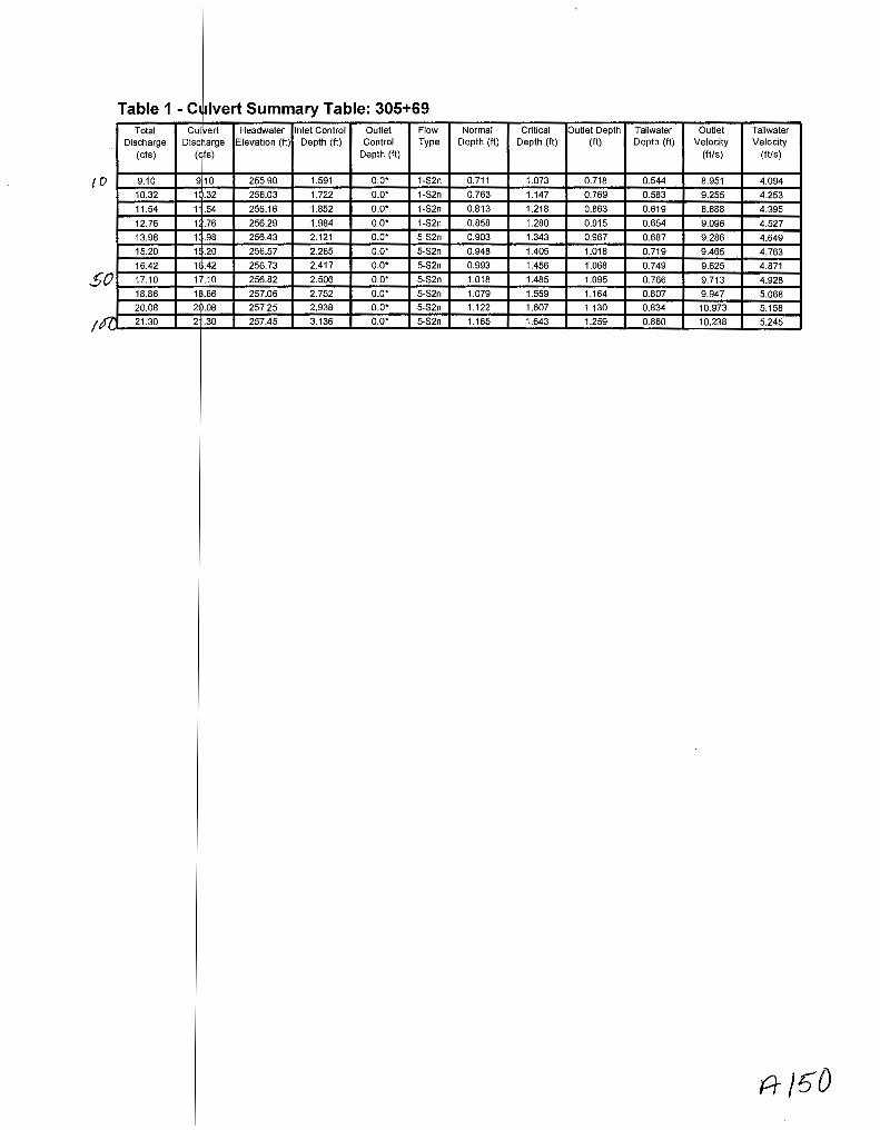
Table 1- C ~lvert Summary Table: 305+69 Total Cu~ert Headwater Inlet Control Outlet Flow Normal Critical Outlet Depth Tailwater Outlet Tailwater
Discharge Dis c arge Elevation (ft) Depth (ft) Control Type Depth (ft) Depth (ft) (It) Depth (ft) Velocity Velocity
(cfs) ( fs) Depth (ft) (ft/s) (ft/s)
0 9.10 910 255.90 1.591 o.o· 1-S2n 0.711 1.073 0.718 0.544 8.951 4.094
10.32 1 .32 256.03 1.722 o.o• 1-S2n 0.763 1.147 0.769 0.583 9.255 4.253
11.54 1 .54 256.16 1.852 o.o• 1-S2n 0.813 1.218 0.863 0.619 8.888 4.395
12.76 1 .76 256.29 1.984 0.0* 1-S2n 0.858 1.280 0.915 0.654 9.096 4.527
13.98 1 .98 256.43 2.121 o.o• 5-S2n 0.903 1.343 0.967 0.687 9.286 4.649
15.20 1 .20 256.57 2.265 o.o· 5-S2n 0.948 1.405 1.018 0.719 9.465 4.763
16.42 1 .42 256.73 2.417 o.o· 5-S2n 0.993 1.456 1.068 0.749 9.625 4.871
5 0 17.10 1 .10 256.82 2.506 o.o· 5-S2n 1.018 1.485 1.095 0.766 9.713 4.928
18.86 1 .86 257.06 2.752 o.o• 5-S2n 1.079 1.559 1.164 0.807 9.947 5.068
20.08 2 .08 257.25 2.938 o.o· 5-S2n 1.122 1.607 1.130 0.834 10.973 5.158
I I(' 21.30 2 .30 257.45 3.136 o.o· 5-S2n 1.165 1.643 1.259 0.860 10.238 5.245
?1-/ 50

f"-,


Site Data-
********************************************************************************
Inlet Elevation (invert): 254.31 ft, Outlet Elevation (invert): 253.36 ft
Culvert Length: 52.01 ft, Culvert Slope: 0.0183
********************************************************************************
Site ta Option: Culvert Invert Data
Inlet tation: 0.00 ft
Inlet levation: 254.31 ft
r of Barrels: 1
Summary - 305+69
Barrel Shape: Circular
Barrel Diameter: 2.00 ft
Barrel Material: Concrete
Embe ment: 0.00 in
Barrel Manning's n: 0.0120
Inlet T pe: Conventional
Inlet E ge Condition: Square Edge with Headwall
Inlet D pression: NONE
ft )5'/

Qso~ rCD ~F,s
CMP c;L'~
e,MP J·S' e,mew
..) moon./ r:P' tH~f;cD
-45 -40 -35 -30
.J.f../3.5b
'21#2.. 7
:J.J./2,. 9
-25 -20
QtOO::: /O~GI=-5
2tltl·f
'il/~.{p
• I
<!:- QSb +ooLJ/;.. bJ () .. 16
oK
-z 1./ t.) .J o'<
-15 -10 -5 0 5 10 15 20
···r,~iflft~ifc~~~M~ .. lffrji~f@--~~·····•••••••••••• ) r·:·~: .. · -45 -40 -35 -30 -25 -20 -15 -10 -5 0 5 10 15 20
3/2+9/.53
-45 -40 -35 -30 -25 -20 -15 -10 -5 0 5 10 15 20
-=t5 -V\ ~
25 30 35 40 45 50
I
~=Ti~t;4k:~[ T.
25 30 35 40 45 50
STA. 312:-73.00, RT TO STA. 312:-86.25, 26.00' RT INSTALL 6' X 18.70' UNDERDRAIN OUTLET W/ 45" ELBOW
25 30 35 40 45 50

~NP 62'tfl..Be.o l
CMP I ~5 2.-NY9itD
Srr!tt>~ fJ-' m..8€.0
~ SC>(f~
'2.43 .. 35"
'2-lJ;l,../
rv-/2- ' 1
~lU UOOS')
'2t/tf,&
2.l/S.(o
24/.f,/ s.Qope- Sh-e(..U..L. 8'fJS4o::: -oo'f:
smco-+k l.b'' ~& ,2by.J -==- 2'5~· yq ... z-a.8. Z3
-60 -55 -50 -45 -40 -35 -30
·--.-·-""""--·-·- ....... __ .._ _____ ..... __ ~
-60 -55 -50 -45 -40 -35 -30
-60 -55 -50 -45 -40 -35 -30
~ -~
s 2. .:o oos-,
J.' ~(V"\bed~ -25 -20 -15 -10 -5 0 5 10 15 20 25 30 35 40 45 50
~;~ ) J§,9''
~;c, f : . : () : '' .. ! ~ ..... ' Hl:.MrNE WCMP ' ::•Y .. --, :-""---~- ..... -~ ·~ ~
t=Mt:Jt:.UU.t=.U" /!Y '· ""'"'
-25 -20 -15 -10 -5 0 5 10
3/2+91.53
-25 -20 -15 -10 -5 0 5 10
15 20
15 20
.;;;:_~~~~~?) 25
25
30 35
STA. 312-73.00, FrT TO STA. 3/2-86.25, 26.00' FrT INSTALL 6' X 18.70'
40
UNDERDRAIN OUTLET W/ 45' ElBOW
30 35 40
45 50
45 50
55
55
55
60
60
60

TRUST
~ -
r··-···~-·-··~·-·n···~···-··- ······-··-··-··-···-\·' ({%;··-···· I 1>- r
I ~~ 1 'r· I '"~; ... .1
CHARTRAND TRUST
"' v ai en + ~ "' ~ "' r II '(.".
~ ·:~s
6'~; "~-~,
B>. ~~
t)~
'
ST A. 3/003.7 3 f(T STA. 3/D-85.76 LT STA. 312•34.64fff ST A. 314+/0.99 fff STA. 3/4+10.89 LT STA. 314•97.98 LT
GRAVEL PAVED GRAVEL PAVED GRAVEL GRAVEL
CURB OPENING
128' 48' 46' 66' 44' 48'
X 3' RJPRAP PAN
DOUGLAS WYMAN CINDY WYMAN
·T 8
• V6 L , . ..., ~~gj . ,;,;;, _,, ;~ E •4.42: "'"'
~
RICHARD H. BROWN KATHERINE BROWN
~ .. -- ·-·· -······.
REMOVE
MARK MERCIER
0 0 z·
~~ "' ...

\)m,()()Jt...\ .;;:2' ~Q) Table 1- S ~mmary of Culvert Flows at Crossing: rte 8 313+00 Headwater Ele vation Total Discharge (cfs) 313+00cmp 2 ft Roadway Discharge Iterations
(ft) embed Discharge (cfs) (cfs)
240.06 20.00 20.00 0.00 1
240.47 28.50 28.50 0.00 1
240.85 37.00 37.00 0.00 1
241.22 45.50 45.50 0.00 1
241.59 54.00 54.00 0.00 1
241.97 62.50 62.50 0.00 1
242.39 71.00 71.00 0.00 1
242.91 79.50 79.50 0.00 1
243.35 86.00 86.00 0.00 1
244.11 96.50 96.50 0.00 1
244.76 105.00 105.00 0.00 1
246.05 119.90 119.90 0.00 Overtopping

Rating Cu e Plot for Crossing: rte 8 313+00
Total Rating Curve Crossing: rte 8 313+00
245_0~--------------------------------------------.
-~ _._.
244_5
244_0
~243.5 c 0
~ 243_0 > 0)
w 242.5 '--0) -ro 242_0 $ -g 241_5 0)
I 241_0
240.5
240_0 ~~~~~~--*=*-~------~~-----.--~ 20 40 60 80 100
Total Discharge (cfs)
A/5~
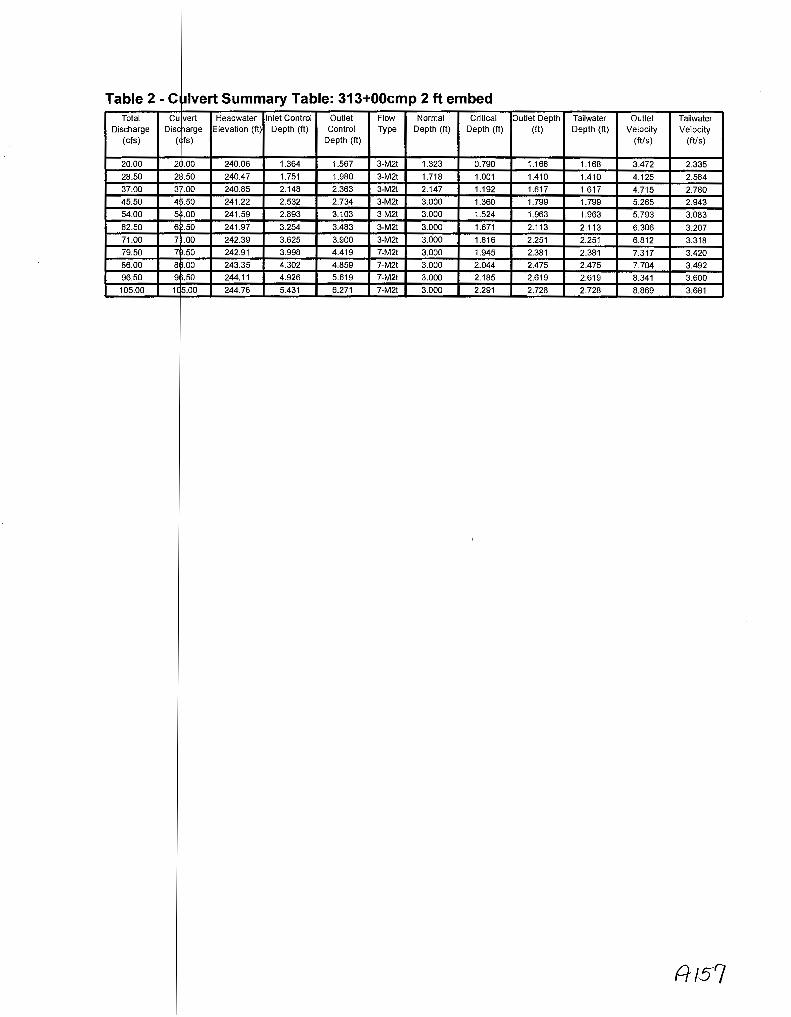
Table 2- C ~lvert Summary Table: 313+00cmp 2ft embed Total Cu vert Headwater Inlet Control Outlet Flow Normal Critical Outlet Depth Tailwater Outlet Tailwater
Discharge Disc arge Elevation (ft) Depth (ft) Control Type Depth (ft) Depth (ft) (ft) Depth (ft) Velocity Velocity (cfs) ( fs) Depth (ft) (ft/s) (ftls)
20.00 2 .00 240.06 1.364 1.567 3-M2t 1.323 0.790 1.168 1.168 3.472 2.335
28.50 2 .50 240.47 1.751 1.980 3-M2t 1.718 1.001 1.410 1.410 4.125 2.584
37.00 3 .00 240.85 2.148 2.363 3-M2t 2.147 1.192 1.617 1.617 4.715 2.780
45.50 4 .50 241.22 2.532 2.734 3-M2t 3.000 1.360 1.799 1.799 5.265 2.943 54.00 5 .00 241.59 2.893 3.103 3-M2t 3.000 1.524 1.963 1.963 5.793 3.083
62.50 6 .50 241.97 3.254 3.483 3-M2t 3.000 1.671 2.113 2.113 6.306 3.207
71.00 7 .00 242.39 3.625 3.900 3-M2t 3.000 1.816 2.251 2.251 6.812 3.318
79.50 7 .50 242.91 3.998 4.419 7-M2t 3.000 1.945 2.381 2.381 7.317 3.420
86.00 8 .00 243.35 4.302 4.859 7-M2t 3.000 2.044 2.475 2.475 7.704 3.492
96.50 9 .50 244.11 4.926 5.619 7-M2t 3.000 2.185 2.619 2.619 8.341 3.600
105.00 1( 5.00 244.76 5.431 6.271 7-M2t 3.000 2.291 2.728 2.728 8.869 3.681
Al57

********************************************************************************
Inlet Elevation (invert): 238.49 ft, Outlet Elevation (invert): 238.23 ft
Culvert Length: 52.00 ft, Culvert Slope: 0.0050
********************************************************************************

Culvert Pe ormance Curve Plot: 313+00cmp 2ft embed
Perfom1ance Curve Culvert: 313-+00cmp 2 ft embed
00 [iJ Inlet Contra~ E!ev Outlet Control Eiev
245~~----------------------------------------~
_244 ...... ~-
c 0
ij 243 > (!)
w @ 242 _,_, ro $ -o m 241 I
240
_,A .... ,. .. ~
/
_ ... --
60 Total Discharge (cfs)

Water Surf ce Profile Plot for Culvert: 313+00cmp 2ft embed
~~ .......
246
245
244
243
~242 c: 0
:w 241 > 11) 240 w
239
238
237
Cr ssing - rte 8 313+00, Design Discharge - 86.0 cfs Culvert- 313+00cmp 2ft embed, Culvert Discharge- 863} ds
~ . ----------------::?( --------- ---· --------·. --------· . --------· ------ --·. --------·. -------· .. --l
Site Data- 13+00cmp 2ft embed
ata Option: Culvert Invert Data
tation: 0.00 ft
levation: 236.49 ft
Culvert Da a Summary - 313+00cmp 2 ft embed
Barr I Material: Corrugated Steel
Emb dment: 24.00 in
Barr I Manning's n: 0.0240 (top and sides)
Man ing's n: 0.0350 (bottom)
ype: Conventional
dge Condition: Thin Edge Projecting
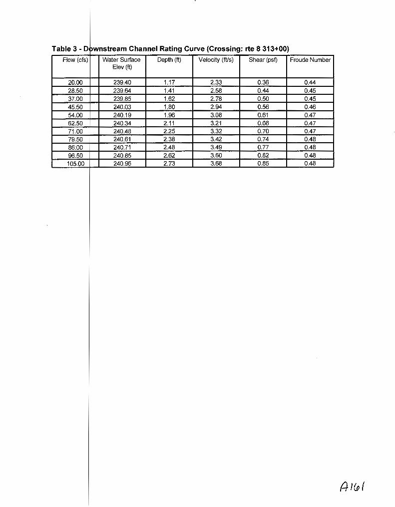
Table 3-D >wnstream Channel Rating Curve (Crossing: rte 8 313+00)
Flow (cfs) Water Surface Depth (ft) Velocity (ft/s) Shear (pst) Froude Number Elev (ft)
20.00 239.40 1.17 2.33 0.36 0.44 28.50 239.64 1.41 2.58 0.44 0.45 37.00 239.85 1.62 2.78 0.50 0.45
45.50 240.03 1.80 2.94 0.56 0.46 54.00 240.19 1.96 3.08 0.61 0.47 62.50 240.34 2.11 3.21 0.66 0.47
71.00 240.48 2.25 3.32 0.70 0.47 79.50 240.61 2.38 3.42 0.74 0.48
86:00 240.71 2.48 3.49 0.77 0.48
96.50 240.85 2.62 3.60 0.82 0.48
105.00 240.96 2.73 3.68 0.85 0.48

Tailwater hannel Data- rte 8 313+00
Tailw ter Channel Option: Trapezoidal Channel
Botto Width: 5.00 ft
Side lope (H:V): 2.00 (_:1)
Chan ellnvert Elevation: 238.23 ft
Roadway ata for Crossing: rte 8 313+00
Road ay Profile Shape: Constant Roadway Elevation
Cres Length: 28.00 ft
Roa way Surface: Paved
Roa way Top Width: 50.00 ft

CMP 1·5' Efl-BW •
Table 1-5 mmary of Culvert Flows at Crossing: rte 8 313+00 Headwater Ele vation Total Discharge (cfs) 313+00cmp 2 ft Roadway Discharge Iterations
(ft) embed Discharge (cfs) (cfs)
240.06 20.00 20.00 0.00 1
240.47 28.50 28.50 0.00 1 240.85. 37.00 37.00 0.00 1
241.22 45.50 45.50 0.00 1
241.59 54.00 54.00 0.00 1
241.97 62.50 62.50 0.00 1 242.39 71.00 71.00 0.00 1 242.91 79.50 79.50 0.00 1
243.35 86.00 86.00 0.00 1
244.11 96.50 96.50 0.00 1
244.76 105.00 105.00 0.00 1
246.05 119.90 119.90 0.00 Overtopping

Rating Cu e Plot for Crossing: rte 8 313+00
Total Rating Curve Crossing: rte 8 313+00
245.0 ---,.j---------------------------,
~ _,__.
244_5
244.0
~·243_5 c 0
~ 243_0 > Q)
w 242_5 '-@
10 242.0 $ -g 241_5 G)
I 241.0
240_5
240_0
~------~~----._~--~--~------~---d 20 40 60 80 100 Tota! Discharge (cfs}

Table 2- C ~lvert Summary Table: 313+00cmp 2ft embed Total Cul~ert Headwater Inlet Control Outlet Flow Normal Critical Outlet Depth Tailwater Outlet Tailwater
Discharge Disc arge Elevation (ft) Depth (ft) Control Type Depth (ft) Depth (ft) (ft) Depth (ft) Velocity Velocity (cfs) ( fs) Depth (ft) (fils) (ft/s)
20.00 2 .00 240.06 1.364 1.567 3-M2! 1.323 0.790 1.168 1.168 3.472 2.335
28.50 2 .50 240.47 1.751 1.980 3-M2t 1.718 1.001 1.410 1.410 4.125 2.584
37.00 3 .00 240.85 2.148 2.363 3-M2! 2.147 1.192 1.617 1.617 4.715 2.780
45.50 4 .50 241.22 2.532 2.734 3-M2t 3.000 1.360 1.799 1.799 5.265 2.943
54.00 5 .00 241.59 2.893 3.103 3-M2t 3.000 1.524 1.963 1.963 5.793 3.083
62.50 6 .50 241.97 3.254 3.483 3-M2! 3.000 1.671 2.113 2.113 6.306 3.207
71.00 7 .00 242.39 3.625 3.900 3-M2! 3.000 1.816 2.251 2.251 6.812 3.318
79.50 7 .50 242.91 3.998 4.419 7-M2! 3.000 1.945 2.381 2.381 7.317 3.420
86.00 8 .00 243.35 4.302 4.859 7-M2! 3.000 2.044 2.475 2.475 7.704 3.492
96.50 9 .50 244.11 4.926 5.619 7-M2! 3.000 2.185 2.619 2.619 8.341 3.600
105.00 10~,00 244.76 5.431 6.271 7-M2! 3.000 2.291 2.728 2.728 8.869 3.681
A-lto~

Inlet Elevation (invert): 238.49 ft, Outlet Elevation (invert): 238.23 ft
Culvert Length: 52.00 ft, Culvert Slope: 0.0050

Culvert Pe formance Curve Plot: 313+00cmp 2ft embed
Perfom1ance Curve Culvert: 313+0Gcmp 2 ft embed
00 [iJ Inlet Contra~ E!ev Outlet Control Elev
245~~----------------------------------------~
~244
c 0
15 243 5) w @ 242 ....... (lJ
$ "'0 (lJ
<D 241 I
240
60 Total Discharge (ds)
AILo/

Water Surf ce Profile Plot for Culvert: 313+00cmp 2 ft embed
Cr ssing- rte 8 313+00, Design Discharge- 86.0 cfs Culvert- 313+00cmp 2ft embed, Culvert Discharge- 86.0 cfs
24!3
245
244
243
~242 c 0
15 241 > <D w 240
239
238
237
23£3
Site Data- 13+00cmp 2ft embed
ata Option: Culvert Invert Data
tation: 0.00 ft
Culvert Da Summary- 313+00cmp 2ft embed
Barre Shape: Circular
Barre Diameter: 5.00 ft
Barre Material: Corrugated Steel
Emb dment: 24.00 in
Barre Manning's n: 0.0240 (top and sides)
Manning's n: 0.0350 (bottom)
Inlet ype: Conventional
Inlet dge Condition: Thin Edge Projecting
Inlet epression: NONE
r ~ .. ----------------";;(

Table 3-D pwnstream Channel Rating Curve (Crossing: rte 8 313+00)
Flow (cfs) Water Surface Depth (ft) Velocity (ft/s) Shear (psf) Froude Number Elev (ft)
20.00 239.40 1.17 2.33 0.36 0.44 28.50 239.64 1.41 2.58 0.44 0.45 37.00 239.85 1.62 2.78 0.50 0.45 45.50 240.03 1.80 2.94 0.56 0.46 54.00 240.19 1.96 3.08 0.61 0.47
62.50 240.34 2.11 3.21 0.66 0.47 71.00 240.48 2.25 3.32 0.70 0.47 79.50 240.61 2.38 3.42 0.74 0.48 86.00 240.71 2.48 3.49 0.77 0.48 96.50 240.85 2.62 3.60 0.82 0.48 105.00 240.96 2.73 3.68 0.85 0.48
Alw q

Tailwater hannel Data- rte 8 313+00
Tailw ter Channel Option: Trapezoidal Channel
Botto Width: 5.00 ft
Side lope (H:V): 2.00 (_:1)
Channel Slope: 0.0050
Channel Manning's n: 0.0400
Channel Invert Elevation: 238.23 ft
Roadway ata for Crossing: rte 8 313+00
Roa way Profile Shape: Constant Roadway Elevation
Cres Length: 28.00 ft
Cres Elevation: 246.05 ft
Roa way Surface: Paved
Roa way Top Width: 50.00 ft

~Jv\P :21 t. r,,~,_t3 t..D I
Table 1-5 ~mmary of Culvert Flows at Crossing: rte 8 313+00 Headwater Ele vation Total Discharge (cfs) 313+00cmp 2 ft Roadway Discharge Iterations
(ft) embed Discharge (cfs) (cfs)
240.06 20.00 20.00 0.00 1 240.47 28.50 28.50 0.00 1 240.85 37.00 37.00 0.00 1 241.22 45.50 45.50 0.00 1 241.59 54.00 54.00 0.00 1
241.97 62.50 62.50 0.00 1 242.39 71.00 71.00 0.00 1 242.91 79.50 79.50 0.00 1
243.35 86.00 86.00 0.00 1
244.11 96.50 96.50 0.00 1
244.76 105.00 105.00 0.00 1
246.05 119.90 119.90 0.00 Overtopping
A- )1

Rating Cu e Plot for Crossing: rte 8 313+00
Total Rating Curve Crossing: rte 8 313+01)
245.0~------------------------------------------~
-~ _.___.
244.5
244_0
~-243.5 c 0
~ 243.0 > (!)
w 242_5 '-(!)
15 242.0 $ -g 241_5 Q)
I 241.0
240.5
240.0 ~~~~~~~--~~~~~=-~~~~
20 40 60 80 100 Total Discharge (cfs)

Table 2- C ~lvert Summary Table: 313+00cmp 2ft embed Total Cu vert Headwater Inlet Control Outlet Flow Normal Critical Outlet Depth Tailwater Outlet Tailwater
Discharge Disc arge Elevation (ft) Depth (ft) Control Type Depth (ft) Depth (ft) (ft) Depth (ft) Velocity Velocity (cis) ( fs) Depth (ft) (ftls) (ft/s)
20.00 2 .00 240.06 1.364 1.567 3-M2t 1.323 0.790 1.168 1.168 3.472 2.335
28.50 2 .50 240.47 1.751 1.980 3-M2t 1.718 1.001 1.410 1.410 4.125 2.584
37.00 3 .00 240.85 2.148 2.363 3-M2t 2.147 1.192 1.617 1.617 4.715 2.780
45.50 4 .50 241.22 2.532 2.734 3-M2t 3.000 1.360 1.799 1.799 5.265 2.943
54.00 5 .00 241.59 2.893 3.103 3-M2t 3.000 1.524 1.963 1.963 5.793 3.083
62.50 6 .50 241.97 3.254 3.483 3-M2t 3.000 1.671 2.113 2.113 6.306 3.207
71.00 7 .00 242.39 3.625 3.900 3-M2t 3.000 1.816 2.251 2.251 6.812 3.318
79.50 7 .50 242.91 3.998 4.419 7-M2t 3.000 1.945 2.381 2.381 7.317 3.420
86.00 8 .00 243.35 4.302 4.859 7-M2t 3.000 2.044 2.475 2.475 7.704 3.492
96.50 9 .50 244.11 4.926 5.619 7-M2t 3.000 2.185 2.619 2.619 8.341 3.600
105.00 1 5.00 244.76 5.431 6.271 7-M2t 3.000 2.291 2.728 2.728 8.869 3.681
Al13

********************************************************************************
Inlet Elevation (invert): 238.49 ft, Outlet Elevation (invert): 238.23 ft
Culvert Length: 52.00 ft, Culvert Slope: 0.0050
********************************************************************************
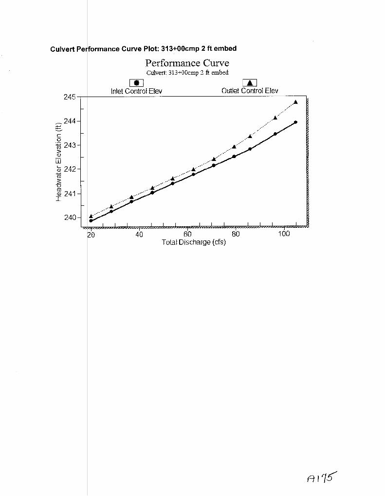
Culvert Pe formance Curve Plot: 313+00cmp 2ft embed
Perfom1ance Curve Culvert: 313+CtCicmp 2 ft embed
00 [iJ Inlet Contra~ E!ev Outlet Control Elev
245~~----------------------------------------~
20 40 60 80 100 Total Discharge (cfs)

Water Su ace Profile Plot for Culvert: 313+00cmp 2ft embed
C ossing - rte 8 313+00, Design Discharge - 86.0 cfs Culvert- 313+00cmp 2ft embed, Culvert Discharge- 86.0 ds
~
246
245
244
243
~242 c 0
~ 241 > G) 240 w
239
238
237
-I ~ . ----------------~,;.( ------------¥ --------· ¥ --------~ ¥ --------· --------· ---------~- -------· ·- --
236 ~~~~~~~~~~--~~----~--~----~--~ -10 0 10 20 30 Station (ft)
Site Data - 13+00cmp 2 ft embed
Site ata Option: Culvert Invert Data
Inlet tation: 0.00 ft
Inlet levation: 236.49 ft
Outlet Station: 52.00 ft
Culvert Oat Summary - 313+00cmp 2 ft embed
Barrel Shape: Circular
Barrel Diameter: 5.00 ft
Barrel Material: Corrugated Steel
Embe ment: 24.00 in
Barrel Manning's n: 0.0240 (top and sides)
Manni g's n: 0.0350 (bottom)
Inlet T pe: Conventional
Inlet E ge Condition: Thin Edge Projecting
Inlet D pression: NONE
40 50 60

Table 3- [ ownstream Channel Rating Curve (Crossing: rte 8 313+00)
Flow (cfs Water Surface Depth (ft) Velocity (ft/s) Shear (psf) Froude Number Elev (ft)
20.00 239.40 1.17 2.33 0.36 0.44 28.50 239.64 1.41 2.58 0.44 0.45 37.00 239.85 1.62 2.78 0.50 0.45 45.50 240.03 1.80 2.94 0.56 0.46 54.00 240.19 1.96 3.08 0.61 0.47 62.50 240.34 2.11 3.21 0.66 0.47 71.00 240.48 2.25 3.32 0.70 0.47 79.50 240.61 2.38 3.42 0.74 0.48
86.00 240.71 2.48 3.49 0.77 0.48
96.50 240.85 2.62 3.60 0.82 0.48
105.00 240.96 2.73 3.68 0.85 0.48
AI

Tailwater hannel Data- rte 8 313+00
ater Channel Option: Trapezoidal Channel
Batt m Width: 5.00 ft
Side Slope (H:V): 2.00 (_:1)
Cha nel Manning's n: 0.0400
Cha nel Invert Elevation: 238.23 ft
Roadway ata for Crossing: rte 8 313+00
Roa way Profile Shape: Constant Roadway Elevation
Cres Length: 28.00 ft
ay Surface: Paved
ay Top Width: 50.00 ft

246
245
244
g243 c 0
::;::::; 242 (iJ
> @
w 241
240
239
238
. - 312+92, De ign Discharge- 86.0 cfs - Culv rert Discharge- 86_() cfs
I +------------------!
I
\ \
\
\
~ ---------- ··-----· -- ·························· ·-- -----------------X
-10 0 10 20 30 40 50 60 Station (ft)

/O
Table 1 - Culvert Summary Table: Culvert 1 Total
Discharge (cfs)
CL /vert Headwater Inlet Control Dis ~arge Elevation {ft) Depth {ft)
( fs)
Outlet Control
Depth (ft)
Flow Type
Normal Depth (ft)
Critical Depth {ft)
Outlet Depth (ft)
Tailwater Depth {ft)
Outlet Velocity
{ft/s)
Tailwater Velocity
(ft/s)
48.00 4 .DO 241.31 3.074 0.0* 1-S2n 1.841 2.071 1.888 1.992 8.221 3.019
53.70 5 .70 241.53 3.294 0.0* 1-S2n 1.968 2.194 2.013 2.104 8.477 3.110
59.40 5 .40 241.75 3.510 0.0* 1-S2n 2.090 2.316 2.138 2.210 8.696 3.193
65.10 6 .10 241.96 3.724 0.0* 1-S2n 2.211 2.432 2.258 2.309 8.907 3.270
70.80 7 .80 242.18 3.942 0.0* 1-S2n 2.331 2.536 2.370 2.404 9.132 3.343
76.50 7 .50 242.41 4.165 0.0* 5-S2n 2.453 2.639 2.460 2.495 9.442 3.411
82.20 8 .20 242.64 4.397 o.o• 5-S2n 2.578 2.743 2.586 2.581 9.581 3.475 ~()~-8~6~.o~o~~~8~.o~o--+-~2~4~2~.8~0--~-4~.~5~~~-~-o~.~o•~-+~5~-S~2~n~--~2.~6~62~-r~2~.8~1~0~~~2~.6~6~9--+-~2.~6~37~-r~9~.6~6~8~~~3~.5~1~6~
93.60 9 .60 243.13 4.893 0.0* 5-S2n 2.833 2.923 2.833 2.745 9.829 3.594
99.30 9~ .30 243.40 >464-... 0.0* 5-S2n 2.981 3.008 2.987 2.822 9.890 3.649
* the retical depth is impractical. Depth reported is corrected.

********************************************************************************
Inlet Elevation (invert): 238.24 ft, Outlet Elevation (invert): 237.98 ft
Culvert Length: 52.00 ft, Culvert Slope: 0.0050
********************************************************************************
Site Data - ulvert 1
Site
Inlet
Culvert Invert Data
Inlet levation: 238.24 ft
Culvert Da Summary - Culvert 1
Barrel Shape: Circular
Barrel Diameter: 4.00 ft
Barrel Material: Concrete
Inlet T pe: Conventional
Inlet E ge Condition: Square Edge with Headwall
Inlet epression: NONE
Roadway D ta for Crossing: 312+92
ay Profile Shape: Constant Roadway Elevation
ength: 50.00 ft
levation: 246.05 ft
ay Surface: Paved
ay Top Width: 28.00 ft

--------
§ X 0 m LL 0
1-:z:: (!)
w :I:
II
10
9
8
7
6
5
3
BUREAU OF PU LIC ROADS JAN. 1963
. 8
.6
.5
(I)
EXAMPLE 5'x 2' Box Q = 75 cfs
Q/8 = 15 cfs/ft.
Inlet HW HW 0 feet
(I) 1.75 3.5
(2) 1.90 3.8
(3) 2.05 4.1
~~:~:o~!~ ~ Flore --+ ~
0:: w I<(
;: 0 <(
HW SCALE WINGWALL w 0 FLARE :z:
(I) 30" to 75"
(2) so•and 15"
(3) o• (extensions of sides)
To use scole (2) or (3) project horizontally.'to scale (1), then use straight inclined line through 0 and Q scales, or reverse as illustrated •
(2) (3)
.30 .35
HEADWATER DEPTH FOR BOX CULVERTS
WITH INLET CONTROL
10
8
7
6
5
4
3
2
1.0
.9
.7
.6
.5
.4
.35

ZONE X
~ <::><)
~
~ ~
APPROXIMATE SCALE
NATIONAL FLOOD INSURANCE PROGRAM
FLOOD INSURANCE RATE MAP
TOWN OF NORRIDGEWOCK, MAINE
(SEE MAP INDEX FOR PANELS NOT PRINTED)
G;J PANEL LOCATION
COMMUNITY-PANEL NUMBER 230178 0016 c
MAP REVISED: MAY 6, 1996

:b oC
~
User Remarks: 384+00
- JJ.7A-UJD -;:::I D/ g
This map Is for general reference only. The US Fish and Wildlife Service Is not responsible for the accuracy or currentness of the base data shown on this map. All wetlands related data should be used in accordance with the layer metadata found on the Wetlands Mapper web site.
norridgewock
Nov 13,2012
Frfishwater Emergent
~eshwater Fores!ediShrub
Esruanne and MariM
freshwater Pond

Water Surf ce Profile Plot for Culvert: 508+86 t'WJ Crossing- 508+86, Design Discharge- 14.2 cfs
Culvert- 508-'-86, Culvert Discharge- 142 cis 212
.211
210
~209 ......, ::'::::'-
§ 208 :;::::; (1J
i1> 207 w
.206
\
\ \
.205
204
203 -10 0 10 20 30 40 50 60
Station (ft)

Table 1 - Culvert Summary Table: 508+86 Total
Discharge (cfs}
7.60
8.60
9.60
10.60
11.60
12.60
13.60
14.20
15.60
16.60
17.60
C lvert Dis::harge
cfs}
.60
.60
.60
1 .60
1 .60
1 .60
1 .60
1 .20
1 .60
1 .60
1 .60
Headwater Inlet Control Elevation (ft} Depth (ft}
206.70 1.402
206.82 1.515
206.92 1.624
207.03 1.731
207.14 1.837
207.25 1.946
207.36 2.057
207.43 2.125
207.59 2.292
207.72 2.419
207.85 2.552
Outlet Control
Depth (ft}
0.0*
0.0*
0.0*
0.0*
0.0*
0.0*
0.0*
0.0*
0.0*
0.0*
0.0*
Flow Type
1-S2n
1-S2n
1-S2n
1-S2n
1-S2n
1-S2n
5-S2n
5-S2n
5-S2n
5-S2n
5-S2n
Normal Depth (ft)
0.526
0.563
0.601
0.630
0.659
0.688
0.717 0.734
0.775 0.803
0.829
Critical Depth (ft}
0.978
1.043
1.103
1.164
1.221
1.272
1.324 1.354
1.422
1.464
1.506
Outlet Depth (ft}
0.533
0.572
0.650
0.685
0.666
0.697
0.794
0.816
0.865
0.899
0.932
Tailwater Depth (ft}
0.589
0.628
0.665
0.700
0.733
0.765
0.795
0.812
0.852
0.879
0.905
Outlet Velocity
(f!ls}
11.224
11.566
10.922
11.105
12.636
12.895
11.694 11.787
11.985
12.122
12.264
Tailwater Velocity
(f!ls}
~.061
4.202
4.333
4.452
4.564
4.668
4.766 4.822
4.946 5.029
5.108

* the retical depth is impractical. Depth reported is corrected.

********************************************************************************
Inlet Elevation (invert): 205.30 ft, Outlet Elevation (invert): 203.40 ft
Culvert Length: 48.04 ft, Culvert Slope: 0.0396
********************************************************************************
Culvert Da Summary - 508+86
Barr I Shape: Circular
Barr I Diameter: 2.00 ft
Barre Manning's n: 0.0120
Inlet ype: Conventional
Inlet dge Condition: Square Edge with Headwall
Inlet epression: NONE
Roadway ata for Crossing: 508+86
Road ay Profile Shape: Constant Roadway Elevation
Crest Length: 50.00 ft
ay Surface: Paved
ay Top Width: 32.00 ft

Route 8
Driveway Culvert Sizing pc. ~ \ "\. '2-Appendix, Final Design
approx .A smooth cmp
location size-It acres Flow estimates Size Estimates
1+40 R 2 4.1 1.25 1.5 USGS Rational smooth cmp
2+90 R 1.5 4.1 1.25 1.5 DA acres Q10 QSO 10 50 size size
5+00 R 1.25 4.1 1.25 1.5 1 1.1 2.3 1.250 1.3
7+50 R 1.25 4.2 1.25 1.5 2 4 5 1.25 1.3
12+70 R 1.25 2.7 1.25 1.5 3 5 7 1.25 1.5
14+00 R 1.25 2.7 1.25 1.5 5 4.1 7.8 1.250 1.5
19+70 L 1.25 <1 1.25 1.25 6 7 11 1.5 1.5
24+25 L 1.25 1.9 1.25 1.25 10 7.3 14.00 1.5 1.75
33+50 R 1.25 <1 1.25 1.25 20 13 24 2 2
49+50 R 1.25 1.6 1.25 1.25 30 17 31 2-2.5 2.5
50+30 R 1.25 <1 1.25 1.25 40 22 40 2.5 2.5
57+50 L 1.5 2 1.25 1.25 so 26 47.00 2.5-3 3
59+00 R 1.5 2 1.25 1.25 70 34 62 3 3
77+00 R 1.25 <1 1.25 1.25 85 39 70 3 3.5
79+00 R 1.25 <1 1.25 1.25 100 46 101 3.5 3.5 83+70 L 1.25 2.5 1.25 1.5 150 62 109 3.5 4
86+30 L 1.25 2 1.25 1.25 200 79 138 4 4 89+20 R 1.25 <1 1.25 1.25 250 95 200
91+70 L 1.25 1 1.25 1.25
92+60 L 1.25 1 1.25 1.25
94+00 L 1.5 1 1.25 1.25
96+10 R 1.25 <1 1.25 1.25
100+10 L 1.5 3 1.25 1.5
102+70 L 1.25 1.5 1.25 1.25
105+50 L 1.25 1 1.25 1.25
113+20 L 1.25 2 1.25 1.25
127+20 L 1.25 to 129 I)Q? 2 2
132+00 L 1.5 2 1.25 1.25
140+80 L 1 remove
146+00 L 1.25 <1 1.25 1.25
147+00 L 1.25 <1 1.25 1.25
147+00 r 1.25 ditch fr m 15 2 2
152+50 L 1.5 1.5 1.5
156+80 L 1.25 <1 1.25 1.25
160+30 R 2 8 2 2
161+50 R 2 8? 2 2
162+00 R 2 8? 2 2
163+00 R 2 8? 2 2
168+00 L 1.5 long, b t <1 1.25 1.25 182+50 L 1.25 <1 1.25 1.25
185+50 R 1.25 1.5 1.25 1.25 186+40 L 1.25 <1 1.25 1.25 187+80 R 1.25 1 1.25 1.25
189+80 R 1.5 1 1.25 1.25 191+75 L 1.25 <1 1.25 1.25
192+50 R 1.5 5.5? 1.5 1.5
194+20 R 1.25 2.9? 1.25 1.5
194+50 L 1.25 <1 1.25 1.25
197+30 L 1.25 <1 1.25 1.25
202+80 R 1.5 2.8 1.25 1.5
205+50 R 1.5 1 1.25 1.25
211+80 R 1.5 1.5 1.25 1.25 215+00 L 1.25 <1 1.25 1.25 216+30 L 1.25 1.5 1.25 1.25
217+50 L 1.25 2 1.25 1.25
217+80 R 2 7.5 2 2
219+90 R 2 10 2 2
220+00 L 1.5 2 1.5 1.5
220+00 R 1.25 10 2 2 from 219+ 90
224+25 R 1.5 2.5 1.25 1.25 226+75 L 1.25 0.5 1.25 1.25 237+40 R 2 8.7 2 2
238+75 R 2 5.9 2 2 244+00 L 1.25 1 1.25 1.25

l 10 E"v.J 'A\-\ c__ .) L, 0 E £.. I'S
244+90 L 1.25 1 1.25
246+00 R 1.5 2 1.25
248+0 L 1.25 <1 1.25
249+90 L 1.25 <1 1.25
250+90 L 1.25 <1 1.25
252+20 L 1.25 <1 1.25
254+50 L 1.25 <1 1.25
256+70 R 1.25 3 1.25
257+00 L 1.25 <1 1.25
257+80 R 1.25 0.5 1.25
258+80 L 1.25 <1 1.25
259+50 L 1.25 <1 1.25
259+60 R 1.25 <1 1.25
265+60 R 1.25 <1 1.25
268+00 R 1.5 0.5 1.25 270+80 R 1.25 0.5 1.25 272+30 R 1.25 1 1.25 280+00 R 1.25 1 1.25 288+20 R 1.25 <1 1.25 292+30 R 1.5 1 1.25
292+60 R 1.25 <1 1.25 295+00 R 1.25 1 1.25
302+00 R 1.5 1.5 1.25
309+75 L 1.5 1.5 1.25
310+80 L 1.5 1.5 1.25
314+00 R 1.5 <1 1.25
315+00 L 1.5 10? 1.5
315+50 R 1.25 5? 1.5 316+40 L 1.5 10? 1.5
317+75 R 1.25 8? 1.5 318+10 L 1.5 5? 1.5
319+75 R 1.25 1.5 320+00 L 1.25 1.5 323+50 L 1.25 1.5 324+50 L 1.25 1.5
325+15 L 1.5 1.5 326+20 R 1.25 1.5
327+00 L 1.25 1.5 328+80 R 1.5 1.5
328+80 R 1.25 1.25
329+75 R 1.25 1.25 330+00 L 1.25 1.25
332+50 L 1.5 1.25
333+50 L 1.5 1.25
334+90 L 1.25 1.25 334+90 R 1.25 1.25
336+30 R 1.25 1.25
337+50 R 1.25 1.25 340+60 R 1.25 1.25
341+80 R 1.25 1.25
343+80 L 1.25 1.25
344+10 L 1.25 1.25 345+20 L 1.25 1.25
345+30 R 1.5 1.5 346+50 R 1.25 1.25
348+00 R 1.25 1.25 352+80 L 1.25 1.25 355+00 L 1.25 1 1.25 357+50 L 1.25 1 1.25 358+25 L 1.25 1 1.25
359+20 L 1.25 1 1.25
359+80 L 1.25 2 1.25
360+50 L 1.25 3 1.25 362+40 L 1.25 3 1.25 to 386+50 included in 4 1.25 500+20 L 1.5 5 1.25 501+10L 1.5 5 1.25 503+00 L 1.5 6 1.5
505+75 L 2 6 2 506+50 L 2 6 2
506+50 R 1.5 1.5 1.5
513+00 R 1.5 1.5 1.5
to 527+50 included in closed ystems
1.25
1.25
1.25
1.25
1.25
1.25
1.25
1.5
1.25
1.25
1.25
1.25
1.25
1.25
1.25
1.25
1.25
1.25 1.25
1.25
1.25
1.25 1.25
1.25
1.25
1.25
1.5
1.5
1.5
1.5
1.5
1.5
1.5
1.5
1.5
1.5
1.5
1.5
1.5 1.25
1.25
1.25
1.25
1.25 1.25
1.25
1.25
1.25 1.25
1.25
1.25
1.25
1.25
Ditch from 352+00 to 312+90 L/R
DA from small to 8-10 acres?
very flat, very sandy
1.5 I ong
1.25
1.25
1.25
1.25 3 55 Lto 503 L
mall to 6 acres? 1.25 s
1.25
1.25
1.25
1.5
1.5
1.5
1.5
1.5
1.5
2 2
1.5 u rban
1.5 "
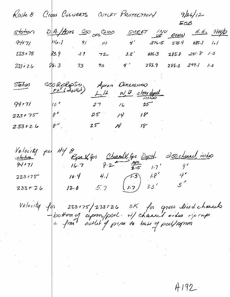
k'ouk a
s-/o-hon
CJt/17/
ZZ3>~ 75
2J3f,z&
Slib&I'J ---CJt/t71
2Z31' 7s-
Z53rZ &
Jl~loc iltj okhtn_ 9~f7/
a~~
D
55 {J u ~..- users ()L)T{_$T PR-orccn~/v 9Pt/t~ &"0-6
4. I~! Qso &1oo Sll.E-FT /NV £ltJII)AJ
.5. G~ E1-ltf}e . c,::s- I ..:..JL£
1& ·I 9/ Ill 1' .,27(,,5 . 273.1 &lJS.J /.I
-51 72- 3,$'' 28t\3 Zf.S. i o29/• ~ j.(J
73 <f6 4' -z<i~. 9 2 ~~. £) zqt.J.; /.tJ
;JfYdn 0/rt.uJ6JC/I],Q
o~caf#= hit wfl. ' '
:?I /{;, ~o-
?II tiC' IY !!?
?;I' zs- /9 1?
d6o c)~ ~~elK:;
7'' ~~~

Date:6/11/2012
' -x-- x-- \
N WI/
N w ~ + 0 0
N w U1
+ 0 0
II ;
; ! j
I !
: I II II ! I !
II l
I n
/ /

-50 -45 -40 -35 -30 -25 -20 -15 -10 -5 0 5 /0 15
2.33+2.6.16
-50 -45 -40 -35 -30 -25 -20 -15 -10 -5 0 5 10 15
20 25 30 35 40 45 50 55 60
20 25 30 35 40 45 50 55 60
65
65
-::rts' -<J:
300
290
285
280 I
70
70
3/0
305
300

[..~::.~~-
(!-
~
REMOVE
ERNEST STEVENS LINDA STEVENS
:
/ /
/~'"
;~. -:;':'>;;;;:> /
\ \ \ 7..
V; ~
ct
EMERY TAYLO
t:.:.~~--~~~~~:::~~===~~·:===~:=~·==~~t.;=::- ~k~:::·~?f.J;J.;Fr I F~ .. ~~~. ,,_,..,
:~:;
--~~. 221+00 222+00
·:~
.. ::\----
N17~·56'14.8"E
--------- -=--·""''''•···'·:::::::.:: / :-; ~; ,;
'~RNEST STEVENS Ll_f;~DA STEVENS
225+00 ~
~-.
,..?. < ·~.:-'~'""" /: --------------~"-------J
\ \\ I irY;:, -\\,( \ ~' ::liil
'":' ;2\ i \0 . ' '\. '' ., r·: . !!'\I \\ 1_~,1; _\;, ': I :, \;
<~.! I: •
---,= 6 6
KENNETH TAY VICKIE TAYLO

Ul
~
~
~
<!. Oi
-~
~
~
13;
c!;
<lJ
~ <tt ~
0 0
~
"'
0
(;;
1?3
[))
~
IJj
"t
~
g)
~
(]) 0
8l
'~ ~ /+J1&

'b_, ·J-..
-REMOVE
93+00
{~~~- ~1t 7~~;J;~);~;(\ .;"::-' ___ _
·---··-··· •;r--··
IJ,/
(?~,.
' :,il; .f.' 1,(''6~'-,.,. '
'<) Xl ·:t~·. t<t:~ <(\
N30°18'59.9"E
c t ~ :> ? ~ ( "cz . e \ ( < ~ ....
I I
I -=6
;;~·
!
'\~,l\'~
II
u 0..
95+00
').5/;:'j ........ ..
\ ~
~
---CLL---
<y~, ............ :r;;·~--~-·-· ~·-·····-- --~-·-"" .... ---··- _____ .. ______ ..... ···-··--
EL -----·······-···-··DYCL .....
96
~;...~·-··--~ -··--·~·~·-··
... S.WEL
:.::~~,~:~;~,::,,;:;~,~,~- - -- ~ ~~ ········ - - - -- - - -
r-, ~~ ~ 1"1·y-, '0
RICHARD LABBE NANCY LABBE
;·y.,...., l")•·v··-.....
Y, ... &11_..__ ...
!JJ[!;
'{7;, REMOVE "~-- ,-~?;c\ "\
..;, ' )
JON~y GOULD 1 GOlJL .. -- D -~')

Oc c::s--Q:
-50 -45 -40 -35 -30 -25 -20 -!5 -/0 -5 0 5 /0 15 20 25 30 35 40 45 50 55 60 65 70
295
290
2B5
2BO
275
270
265 I i
-50 -45 -40 -35 -30 -25 -20 -15 -10 -5 0 5 10 15 20 25 30 35 40 45 50 55 60 65 70
94+71.41
-50 -45 -40 -35 -30 -25 -20 -15 -/0 -5 0 5 /0 !5 20 25 30 35 40 45 50 55 60 65 70
295
290
2B5
2BO
-
275

·~ ....
' i
Permiss ble Velocities: Grass and Earth Lined Channels
Channel Sl pe Lining
0.5% Bennudagrass Reed canaxy grass Tall fescue Kemucky bluegrass Gnlsslegume mixture Red fescue Redtop Sericea le:pedeza Annuallespedeza
Channel S ope Lining
Small . (temp) S-1 OOAt Bermudagrass
Reed canacygrass Tall fescue Kentucky bluegrass Gtasslegume mixture
> 10% Bennudagrass Reed can uygr as s Tall fescue Kentucky bluegrass
PermisSible Velocity*
1.8~ ~-~
1.5 mls 1.5 mls 1.2 mfs L2m/s L2m/s 1.2 mls 1.2m/s
Permissible Velocity*
~ 1.2 m/s 1.2 m/s 0.9m/s 1.2 m/s 0.9 m/s 0.9 mls 0.9m/s
erodible soils, decrease permissible velocities by 25%
Earth Linings
(noncolloidal) {noncolloidal)
(noncolloidaJ) Finn Loam
Fine vel · StiffCl (very colloidal) Grad~ Loam to Cobbles (noncolloidal) Graded, Silt to CoWles (colloidal) Alluvial Silts (noncolloidal) Alluvial Silts (colloidal) Coarse (noncolloidal) Cobbl and Shingles Shales d Hard Pans
Permissible Velocity
Referenced from Model Drainage Manual, 1991, American Association of State l-tiahur v :md Transuortation. Officials (AASHrO).
\
;v~ .:u , .. :_,_\

ooz f) -
:I: '<
~
0. 0
.., c
s:.u
r+ CD
'co -h -0
0
~ c::
~ • "tJ ~ -s:.u
-~-::: ::J
< ~ ~ -· . r
CD +
~ 00 ,_,., ;o
"'
-
z 9 !:: :::l CD (/)
w
II J-- "' +
0 0
0 (j)
I r ....>.
I -...! '< "- I
~ N 0 0 :;: ....>.
en w 0 3 en CD
l ~ <ri
"' 0 0 <n
Route 8 Appendix <200

Storm S1ewer Summary Report Page 1
Line
1'"1'" Flow Line Line Invert Invert Line HGL HGL Minor HGL Dns
No. rate size length ELDn ELUp slope down up los Junct line (cfs) (in) (ft) (ft) (ft) (%) (ft) (ft) (ft (ft) No.
5.1 I 1 11 +85 L oGt 0.00 18 c 10.0 355.20 355.50 3.000 356.25 356.55 nla 356.55 j End
2 9+00 IL to 111+85 L 0.00 12 c 185.0 355.50 356.90 0.757 357.02 357.42 n/a 357.56 1 I
3 11+8 5 cro~s line 0.00 18 c 51.0 355.50 356.98 2.902 356.90 357.88 n/a 357.88 1
I
_i
I I
I route_8 I
Number of lines: 3 ~un Date: 06-17-2013
NOTES: c f ci~; e = ellip; b =box; Return period= 10 Yrs. ; j- Line contains hyd. jump.
I Hydraflow Storm Sewers 2005
Route 8 Appendix <201

Storm Sewer Inventory Report Page 1
Line Alignment Flow Data Physical Data Line ID No.
Dnstr Line Defl June Known Drng Runoff Inlet Invert Line Invert Line Line N J-loss Inlet/ line length angle type Q area coeff time EIDn slope EIUp size type value coeff RimEl No. (ft) (deg) (cfs) (a c) (C) (min) (ft) (%) (ft) (in) (n) (K) (ft)
--
---------------- ------------ --------------- - -- --- --- ----------- -- ------------ ---- --- -- ------- ---- -------------- ------------- --------------- ------------- - -- -------- - --- ---------- --- ----- -- -- ------------ ----- ----- - - ------- ----- ---- ------ -- ----- -- --
1 End 10.0 0.0 Grate 0.00 0.22 0.90 5.0 355.20 3.00 355.50 18 Cir 0.013 1.48 363.50 11+85 Lout
2 1 185.0 0.0 Grate 0.00 0.27 0.90 5.0 355.50 0.76 356.90 12 Cir 0.013 1.00 363.90 9+00 L to 11+85 L
3 1 51.0 80.0 Hdwl 5.50 0.00 0.00 5.0 355.50 2.90 356.98 18 Cir 0.013 1.00 363.50 11 +85 cross line
i
--!
route_S Number of lines: 3 Date: 03-11-2013 ------------------
Hydraflow Storm Sewers 2005 Route 8 Appendix <202

I : .
Stor"1 ~ewer Summary Report Line No.
2
3
qneiD
I '· 11+j5 L:out
9+00 L to 11+85 L I :
11 +85 cross line
route_8
Flow rate (cfs)
7.52
1.24
5.50
Line size (in)
18 c
12 c
18 c
Line length
(ft)
Invert ELDn
(ft)
Invert ELUp (ft)
Line slope (%)
HGL down (ft)
HGL up (ft) ~
nor s )
HGL Junct (ft)
Page 1
Dns line No.
10.0 1355.20 1355.50 I 3.000 1356.25 1356.55 I 01.75 1356.55 I End
185.0 355.50 356.90 0.757 357.02 357.42 0.14 357.56 1
51.0 I 355.50 I 356.98 I 2.902 I 356.90 I 357.88 I nVa I 357.88 i I 1
Number of lines: 3 1 Run Date: 03-11-2013
NOTES: c 1 cir; e = ellip; b =box; Return period= 10 Yrs. ; j- Line contains hyd. jump.
Hydraflow Storm Sewers 2005
Route 8 Appendix <203

Storm Sewer Tabulation Page 1
Station Len Drng Area Rnoff Area x C Tc Rain Total Cap Vel Pipe Invert Elev HGLEiev Grnd I Rim Elev Line ID coeff (I) flow full
Line To I ncr Total I ncr Total Inlet Syst Size Slope Up Dn Up Dn Up On Line
(ft) (ac) (ac) (C) (min) (min) (in/hr) (cfs) (cfs) (ft/s) (in) (%) (ft) (ft) (ft) (ft) (ft) (ft) -- --
·-·
--- ---- ----- --------- ---------- - --------- ----------- - ------ --- --- --- ---- --- -------- ------- -- -- ------ - - - - - -- ----- --------- -------- --- --- - ------- -- --- --- ------ ------- -- ------ ------ --------------
1 End 10.0 0.22 0.49 0.90 0.20 0.44 5.0 7.0 4.6 7.52 18.19 5.71 18 3.00 355.50 355.20 356.55 356.25 363.50 360.00 11+85 Lout
2 1 185.0 0.27 0.27 0.90 0.24 0.24 5.0 5.0 5.1 1.24 3.10 2.29 12 0.76 356.90 355.50 357.42 357.02 363.90 363.50 9+00 L to 11 +85
3 1 51.0 0.00 0.00 0.00 0.00 0.00 5.0 5.0 0.0 5.50 17.89 4.10 18 2.90 356.98 355.50 357.88 356.90 363.50 363.50 11 +85 cross line
route_S Number of lines: 3 Run Date: 03-11-2013
NOTES: Intensity= 32.56/ (Inlet time+ 7.70)" 0.73; Return period= 10 Yrs.
Hydraflow Storm Sewers 2005 Route 8 Appendix <204

Inlet Report Page 1
Line Inlet ID Q= Q Q Q June Curb Inlet Grate Inlet Gutter Inlet Byp No CIA carry capt byp type line
Ht L area L w So w Sw Sx n Depth Spread Depth Spread Depr No (cfs) (cfs) (cfs) (cfs) (in) (ft) (sqft) (ft) (ft) (ftfft) (ft) (ftfft) (ft/ft) (ft) (ft) (ft) (ft) (in)
- ---------------------------------- --- ------ -- 1 -- -- -11+85L- --- --- - 1~01 0:00-- 1:01·- O:GO- Grate- --0.0 0.00- ·0:00 --- 2:00-- ·2:00 --- 0:003 -5,00 0:060- 0:038- 0.013 0.26 4.33-- 0.25- 4.48 - 1.00 - --Off -
2 9+00 L 1.24 0.00 1.24 0.00 Grate 0.0 0.00 0.00 2.00 2.00 0.003 5.00 0.060 0.030 0.013 0.28 4.67 0.27 4.57 0.00 1
3 11+85 R 5.50* 0.00 5.50 0.00 Hdwl 0.0 0.00 0.00 0.00 0.00 Sag 0.00 0.000 0.000 0.000 0.00 0.00 0.00 0.00 0.00 Off
I
!
' route_S I Number of lines: 3 I Run Date: 03-11-2013
NOTES: Inlet N-Values = 0.016; Intensity= 32.56 I (Inlet time+ 7.70)" 0.73; Return period= 10 Yrs.; *Indicates Known Q added
Hydraflow Storm Sewers 2005 Route 8 Appendix <205

"' ~ ~ ~ ~
\ ~
,,.,--~~
i-(2.__ Q_
~ -~ \.r ~ 0<
~;::_
"\'--~
J I
, I
I
Route 8 Appendix <206

Stc . ~ Sewer Tabulation ( ( Page 1
~--Station I Len i Drng Area i Rnoff ~-~rea x C ; Tc - ! Rai~·-,,-r:-ot-al-1 Cap i Vel ~- Pipe ; Invert Elev HGL Elev Grnd I R_im Elev \ Line 10 , ··-, -, r------< coeff ; . ·· (I) flow ; full ' . .... , , --
____ !Line I.I~e 1 liner ,_To_ta_l 1--1-l_n_cr_[ Total j_ln_le_t _sy_st_: -l--j--1----rS..i~~-LSJ.ope ,___up_1 o -UP-rDn-,-Up---i-Dn-~----_ -_ -+~---
1 ' I ;>y··· ' I I I i I i I I I : ! I I VL -1 I ! I ' I I ' I i . I i I !
i I i I ,olf I J I I .,. I ! !I_ ~~· I / I I I I i I I I I : I I i I i ' i I '
' I , I r ' j I ! ·1• I I I I '! I'
I I l i I i I f I I I I . , I i l I I
!
I ' I I
I I ! I I I I I I
I I I I I I I I
I I I l l I i ! I I I I I I I I I I . I I ! I
Project File: 16+70R_out.stm I N~mber of lines: 1
I NOTES: Intensity= 32.56/ (Inlet time+ 7.70) "0.73; Return period"' 10 Yrs. i
I Run Date: 08-29-2012
I
j I
,_~
_j H~dra~ow S!crm Sewers 2005
Route 8 Appendix <207

::,-,..
lnL _Report ,I \. ( Page 1
Line Inlet 10 I Q = i Q- Q ~-~-Ju-n~- ! Curb Inlet Grate Inlet .. , Gutter ~-- Inlet j ~yp No ' CIA I carry capt byp i type · , , i -
1 .•• ··-: - , hne
I i I ~-~- !:_'area 0-_L_Y'L_~I____w_l S_w_'_Sx_J __ o_J)_epth__Sp[ead_'_Oeptn Spreact+Depr-j-N0-1---
-~-=-i -=-~~1-6-+~70--R·~-----~.--!jf--~:-:,: -::c ·~re I ::, ·r :.~/:'"1~~ ','~-·~:~~~ ~~~~~[~ ,::" i :~ ,-,~:-!-::~ ~>i :':l~ 1
l I' I I i I ' I i ! I : !
I i I i II I I i I I : ! il ,1 I I I . I '1
1
! 'I I I I I Ill., . i I I ' ! ' 1 • r i ' , · 1 1 I · I . , 1 ,
I I I I ! I I I I I I I ~,· I
1/ I 1
1 I I I I ,,. 'I I I I I I ' i
i . ! ' I ' I ' j i I I I I . I ' I '
I I . , I ., '
i !
, I I I
I I i
I I I I I I . ' i ! L I I - . i ! f I f ! ProjeotFne; 16<7DR_oot•tm I N"m"•""'"' 1 1 Roo Date~ 08-21>-2012 ~ j NOTES: Inlet N-Values = 0.016; Intensity= 32.56/ (lnlettime + 7.70) 11 0.73; Return period'"' 10 Yrs. ; *Indicates Known Q added
Hydrallm.• S!orm Se•11ers 2-:JOS
Route 8 Appendix <208

Hydraflow Plan View
Outfall .......................................... ··········-·····- ................................ ···-····--········-·····-· ······iN n~oo R
Project File: 22+00R_out.stm l No. Lines: 1 1 09-17-2012
Hydraflow Storm Sewers 2005
Route 8 Appendix <209

Storm Sewer Tabulation Page 1
Station Len DrngArea Rnoff Area x C Tc Rain Total Cap Vel Pipe Invert Elev HGL Elev Grnd I Rim Elev Line ID coeff (I) flow full
Line To I ncr Total I ncr Total Inlet Syst Size Slope Up Dn Up Dn Up Dn Line
(ft) (ac) (ac) (C) (min) (min) (in/hr) (cfs) (cfs) (ft/s) (in) (%) (ft) (ft) (ft) (ft) (ft) (ft)
- - ----- ------ -- ---- - ---------- ----- -- .... I -, - ------- ------------
12 1 End 200.0 0.06 0.06 0.90 0.06 0.06 5.0 5.0 5.1 0.29 2.11 1.89 - (f35- 331.70- 331.00- -331 ~95 33T.25 -- -336:70 -336:00 -2o+oo to 22'~'00R
I
!
I
I
Project File: 22+00R_out.stm Number of lines: 1 Run Date: 09-17-2012 !
NOTES: Intensity= 32.56 I (Inlet time+ 7.70)" 0.73; Return period= 10 Yrs. ! - --- -
Hydraflow Storm Sewers 2005 Route 8 Appendix <210

Inlet Report Page 1
Line Inlet ID Q= Q Q Q June Curb Inlet Grate Inlet Gutter Inlet Byp No CIA carry capt byp type line
Ht L area L w So w Sw Sx n Depth Spread Depth Spread Depr No (cfs) (cfs) (cfs) (cfs) (in) (ft) (sqft) (ft) (ft) (ft/ft) (ft) (ft/ft) (ft/ft) (ft) (ft) (ft) (ft) (in)
-------- ----------------------------------------------------
- -- 1 - - 22+00R - -0:29- 0.00 - 0.29--- 0:00- -Grate - 0.0- -0.00 0.00 -2:00- -2:00- 0:001- -5.00 -- 0:030- 0.030- 0:013- 0:16- 5:33 0:18. - -3:84 - 1:00 Off
I I
I
!
Project File: 22+00R_out.stm I Number of lines: 1 I Run Date: 09-17-2012
NOTES: Inlet N-Values = 0.016; Intensity= 32.56 I (Inlet time+ 7.70)" 0.73; Return period= 10 Yrs.; *Indicates Known Q added -
Hydraflow Storm Sewers 2005 Route 8 Appendix <211

I '< 0. iil
~ rn 0 3
f '" " 0 0
"'
~ 0 + en 0 :;c
-
z ~ c: ::::s CD ~ ......
-0 w
I ...... ...... I
N 0 ...... w
~
0 c:
~
-Q) ::s
~ < -· (I)
~ n
-10-0 + '-'"' 0 ;u
'
'
'
'
Route 8 Appendix <212

i I
Storm /S!ewer Summary Report Page 1
Line
I""'" Flow Line Line Invert Invert Line HGL HGL Mir or HGL Dns
No. rate size length ELDn ELUp slope down up los Junct line (cfs) (in) (ft) (ft) (ft) (%) (ft) (ft) (ft (ft) No.
1 40+50 R outlet 3.34 12 c 35.0 359.50 360.00 1.429 360.28 360.78 n/a 360.78 j End
I
I I
I
' I
I
I
!
I
I I I
' I
I run Date: 03-11-2013 40+50R I !
Number of lines: 1
NOTES: c i c~; e = ellip; b =box; Return period= 10 Yrs. ; j- Line contains hyd. jump. I IHydraflow Storm Sewers 2005
Route 8 Appendix <213

Storm Sewer Tabulation Page 1
Station Len Orng Area Rnoff Area x C Tc Rain Total Cap Vel Pipe Invert Elev HGLEiev Grnd I Rim Elev Line 10 coeff (I) flow full Line To I ncr Total I ncr Total Inlet Syst Size Slope Up On Up On Up On Line (ft) (ac) (ac) (C) (min) (min) (in/hr) (cfs) (cfs) (ft/s) (in) (%) (ft) (ft) (ft) _(ttL (ft) (ft) ----------- -·-·· ---.----
- - -- -- - 1- - - - -- -
1 End 35.0 1.60 1.60 0.41 0.66 0.66 5.0 5.0 5.1 3.34 4.26 5.11 12 1.43 360.00 359.50 360.78 360.28 365.50 365.50 40+50 R outlet
40+50R Number of lines: 1 Run Date: 03-11-2013
NOTES: Intensity= 32.56 I (Inlet time+ 7.70)" 0.73; Return period= 10 Yrs.
Hydraflow Storm Sewers 2005
Route 8 Appendix <214

Inlet Report Page 1
Line Inlet ID Q= Q Q Q June Curb Inlet Grate Inlet Gutter Inlet Byp No CIA carry capt byp type line
Ht L area L w So w Sw Sx n Depth Spread Depth Spread Depr No (cfs) (cfs) (cfs) (cfs) (in) (ft) (sqft) (ft) (ft) (ft/ft) (ft) (ft/ft) (ft/ft) (ft) (ft) (ft) (ft) (in)
----------------------------- - -- - -- I
1 40+50R 3.34 0:00 3:34 . 0.00 Grate 0.0 o:oo - 0.00 2:00 2.66- 0.027 5.00 .. 0.060 0.030 0.013 0.27 4.50 0.24 5.22 1.00 Off
40+50R I Number of lines: 1 I Run Date: 03-11-2013
NOTES: Inlet N-Values = 0.016 ; Intensity= 32.56 I (Inlet time + 7. 70) A 0. 73; Return period = 10 Yrs. ; * Indicates Known Q added
Hydraflow Storm Sewers 2005 Route 8 Appendix <215
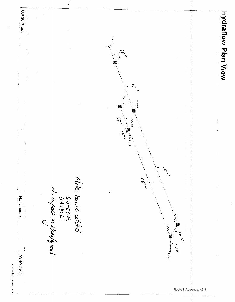
Q) 00 + C1l 0 ;o
. 0 s::::
,_
z 9 c. ::J CD ~ CX>
0 VJ
I ...... CD N 0
VJ
~ ~ '.
~~ ~ ~~ VI ....... ~ i- ~-~C> 0.~
t \'~ ~ Q"~~
........ ~ " ' \ \.
\\.~-..J
\.
?;""'-+ -~ -r
., \ 'l\ \ \, \ \ \
\,_
\.
\.
\ •. \ \~ .•.
\ \~ ~ ;=~._
Ill /
'·" ,·'/.to.. ~\. ~ ' Ill ~ ~
-1 --
-r.u ::l
< -·
Route 8 Appendix <216

i I !
Storm Sewer Summary Report Page 1 I
Line I Line ID Flow Line Line Invert Invert Line HGL HGL I'll in or HGL Dns No. rate size length ELDn ELUp slope down up h ss Junct line
I (cfs) (in) (ft) (ft) (ft) (%) (ft) (ft) (~) (ft) No.
1 I ,
67+50 to 68+50 R o 6.32 24 c 45.0 257.00 262.50 12.222 257.39 263.39 0 28 263.39 End
I : 15 c 262.50 265.50 0.909 263.68 266.10 266.10j 2 64+20 to 67+50 R 2.22 330.0 na 1
I . 3 63+l2 too 64+20R 0.41 12 c 70.0 265.50 268.00 3.571 266.32 268.27 na 268.27 j 2
4 67 +do cross L to R 3.55 18 c 40.0 262.50 264.00 3.750 263.67 264.72 na 264.72 j 1 I I i
5 63+80 to 67+30 L 3.57 15 c 350.0 264.00 267.20 0.914 264.87 267.96 na 267.96 j 4 I .
6 62+~0 tel 63+80 L 3.39 15 c 150.0 267.20 271.00 2.533 268.17 271.74 na 271.74j 5 I ,
7 61 +80 to 62+30 L 3.22 15 c 49.0 271.00 275.00 8.163 271.94 275.72 na 275.72 j 6 I '
8 64+~0 ~ inlet 1.63 15 c 7.0 268.00 268.20 2.857 268.33 269.00 0 06 269.06 2 I .
'
'
!
I
I
I
I
68+50 R out I , Number of lines: 8 IR un Date: 03-19-2013
NOTES: c = ~ir; ';e = ellip; b =box; Return period= 10 Yrs. ; j- Line contains hyd. jump.
I .
I H draflow Storm Sewers 2005 I
Route 8 Appendix <217

Storm Sewer Tabulation Page 1
Station Len DrngArea Rnoff Area x C Tc Rain Total Cap Vel Pipe Invert Elev HGL Elev Grnd I Rim Elev Line ID coeff (I) flow full
Line To I ncr Total I ncr Total Inlet Syst Size Slope Up On Up On Up Dn Line
(ft) (ac) (ac) (C) (min) (min) (in/hr) (cfs) (cfs) (ftls) (in) (%) (ft) (ft) (ft) (ft) (ft) (ft) ----------------·-------
-- ---- ----- -- ------- ----- ------- --
- - --- - I -- --- -J
1 End 45.0 0.44 2.63 0.61 0.27 1.58 5.0 10.0 4.0 6.32 79.07 9.55 24 12.22 262.50 257.00 263.39 257.39 268.50 265.00 67+50 to 68+50
2 1 330.0 0.10 0.83 0.90 0.09 0.49 5.0 7.2 4.5 2.22 6.16 2.85 15 0.91 265.50 262.50 266.10 263.68 273.50 268.50 64+20 to 67+50
3 2 70.0 0.09 0.09 0.90 0.08 0.08 5.0 5.0 5.1 0.41 6.73 1.49 12 3.57 268.00 265.50 268.27 266.32 273.50 273.50 63+52 too 64+20
4 1 40.0 0.08 1.36 0.90 0.07 0.82 5.0 8.2 4.3 3.55 20.34 3.32 18 3.75 264.00 262.50 264.72 263.67 270.00 268.50 67+50 cross L to
5 4 350.0 0.08 1.28 0.90 0.07 0.75 5.0 6.2 4.8 3.57 6.17 4.26 15 0.91 267.20 264.00 267.96 264.87 272.00 270.00 63+80 to 67+30 L
6 5 150.0 0.05 1.20 0.90 0.05 0.68 5.0 5.3 5.0 3.39 10.28 3.92 15 2.53 271.00 267.20 271.74 268.17 277.00 272.00 62+30 to 63+80 L
7 6 49.0 1.15 1.15 0.55 0.63 0.63 5.0 5.0 5.1 3.22 18.45 3.82 15 8.16 275.00 271.00 275.72 271.94 281.00 277.00 61 +80 to 62+30 L ,
8 2 7.0 0.64 0.64 0.50 0.32 0.32 5.0 5.0 5.1 1.63 10.92 4.16 15 2.86 268.20 268.00 269.00 268.33 272.00 273.50 64+20 R inlet
68+50 Rout Number of lines: 8 Run Date: 03-19-2013
NOTES: Intensity= 32.56 I (Inlet time+ 7.70) A 0.73; Return period= 10 Yrs.
Hydraflow Storm Sewers 2005 Route 8 Appendix <218

Inlet Report Page 1
Line Inlet ID Q= Q Q Q June Curb Inlet Grate Inlet Gutter Inlet Byp No CIA carry capt byp type line
Ht L area L w So w Sw Sx n Depth Spread Depth Spread Depr No (cfs) (cfs) (cfs) (cfs) (in) (ft) (sqft) (ft) (ft) (Wft) (ft) (Wft) (Wft) (ft) (ft) (ft) (ft) (in)
--·· --------- ~-------------------------
1 67-1-50 R . ~ ~ 1.37 0:00 1;37 0.00 Grate I~~ 0.0 0.00 -- 0.00 2.00 2.00 o.-o6o !j:oo-- 1J:06() 0.030 o:o13 -0.17-- 2.83 0.15 3.17 1.00 Off
2 64+20 R 0.46 0.00 0.46 0.00 Grate 0.0 0.00 0.00 2.00 2.00 0.010 5.00 0.060 0.030 0.013 0.16 2.67 0.14 2.96 1.00 1
3 63+52 R 0.41 0.00 0.41 0.00 Grate 0.0 0.00 0.00 2.00 2.00 0.010 5.00 0.060 0.020 0.013 0.15 2.50 0.12 3.30 1.00 2
4 67+30 L 0.37 0.00 0.37 0.00 Grate 0.0 0.00 0.00 2.00 2.00 0.060 5.00 0.060 0.030 0.013 0.10 1.67 0.09 1.95 1.00 1
5 63+80 L 0.37 0.00 0.37 0.00 Grate 0.0 0.00 0.00 2.00 2.00 0.010 5.00 0.040 0.030 0.013 0.12 3.00 0.13 2.72 1.00 4
6 62+30 L 0.23 0.00 0.23 0.00 Grate 0.0 0.00 0.00 2.00 2.00 0.060 5.00 0.060 0.030 0.013 0.09 1.50 0.08 1.63 1.00 Off
7 61+75L 3.22 0.00 3.22 0.00 Hdwl 0.0 0.00 0.00 0.00 0.00 Sag 0.00 0.000 0.000 0.000 0.00 0.00 0.00 0.00 0.00 Off
8 64+1 0 field R 1.63 0.00 1.63 0.00 Hdwl 0.0 0.00 0.00 0.00 0.00 Sag 0.00 0.000 0.000 0.000 0.00 0.00 0.00 0.00 0.00 Off
I
68+50 Rout I Number of lines: 8 I Run Date: 03-19-2013
NOTES: Inlet N-Values = 0.016; Intensity= 32.56 I (Inlet time+ 7.70) A 0.73; Return period= 10 Yrs. ; *Indicates Known Q added --- -
Hydraflow Storm Sewers 2005 Route 8 Appendix <219
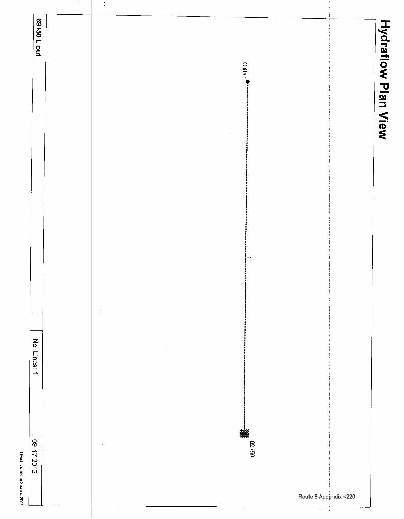
' Q) CD + U'l 0 r-0 c -
0 ~ ~
'~
1---
z 9 c: :::J CD ~ _,.
f--0 O'l <0 <.o I + _,.
01 "'-! 0 I
I'V 0 _,. I'V
Route 8 Appendix <220

Storm Sewer Tabulation Page 1
Station Len Drng Area Rnoff Area x C Tc Rain Total Cap Vel Pipe Invert Elev HGLEiev Grnd I Rim Elev Line ID coeff (I) flow full
Line To I ncr Total I ncr Total Inlet Syst Size Slope Up Dn Up Dn Up Dn Line
(ft) (ac) (ac) (C) (min) (min) (in/hr) (cfs) (cfs) (ft/s) (in) (%) - (ft) __ _i_f!l_ _ _j!!t_ __ __ j_f!l __ _(f!)_ _ _(f!L_ ----------~ ---
.. -·---·-- ·-
I - .... . ....
1 End 100.0 0.18 0.18 0.85 0.15 0.15 5.0 5.0 5.1 0.78 3.56 3.28 12 1.00 256.00 255.00 256.37 255.32 261.00 261.00 69+50 to 68+50 L
69+50 Lout Number of lines: 1 Run Date: 09-17-2012
1 NOTES: Intensity= 32.56 I (Inlet time+ 7.70) 1\ 0.73; Return period= 10 Yrs. --
Hydraflow Storm Sewers 2005 Route 8 Appendix <221

Inlet Report Page 1
Line Inlet ID Q= Q Q Q June Curb Inlet Grate Inlet Gutter Inlet Byp No CIA carry capt byp type line
Ht L area L w So w Sw Sx n Depth Spread Depth Spread Depr No (cfs) (cfs) (cfs) (cfs) (in) (ft) (sqft) (ft) (ft) (ft/ft) (ft) (ft/ft) (ft/ft) (ft) (ft) (ft) (ft) (in)
·----·-------·---------------- ---- ---- ---------·-
1 69+50 0.78 .... 0.00 0.78 ... o:oo ... Grate 0.0 0.00 0.00 2.00 2.db . 0.616 5.00 0.030 0.030 0.013 0.15 5.00 0.17 3.60 1.00 Off
I
I
69+50 Lout I Number of lines: 1 I Run Date: 09-17-2012
NOTES: Inlet N-Values = 0.016; Intensity= 32.56/ (Inlet time+ 7.70) A 0.73; Return period= 10 Yrs.; *Indicates Known Q added
Hydraflow Storm Sewers 2005 Route 8 Appendix <222

~ .... + 0 0 ;:c 0 c: -c;; - 0
c g
-r.u :::s < -· (I)
~ ~
~ :i + "' 0
;;o
""
...,. -.j
"" + r
0 0
r
f--- "'
z 9 r ::J CD '""' ~ 01
II
1--- ~~ 0 ~ co + I "' ...>. =
-.J ~
I N 0 ...>. 1\)
i I
Route 8 Appendix <223

Hydraflow Plan View
72<!-50 L
72+00 L
' j
~/
,/7hSO R
Outfall• ... ••
71 +00 R outlet
?S+5GL1 6
"7t:+.:;,'
:!~~?~3:1~kJ
;<)6l-6astlte 77 rZIJ /2,
/!vnol/(_d__
H6 '~tc) ~Mali
No. Lines: 8
77+20 R
•
06-17-2013
Hydraflow Storm Sewers 2005 Route 8 Appendix <224

I
Stor~ ~ewer Summary Report Page 1
Line No.
Line ID
I 71 +IDO to 71 +50 R
I
Flow rate (cfs)
9.02
2 71+SOL!o71+50R I 2.19
3
4
5
6
7
8
inletlto qrossline at
crosj lille 600+50
71 +50 R to 75+50 I
crosk line at 75+50 I ,
75+50 R to 77+20 !
field I inlet to 75+50
I 71 +00 R outl:et
1.99
1.30
6.63
4.75
0.82
0.27
Line size (in)
18 c
18 c
18 c
18 c
18 c
18 c
12 c
12 c
Line length
(ft)
65.0
65.0
10.0
50.0
400.0
48.0
170.0
5.0
Invert ELDn
(ft)
Invert ELUp (ft)
260.00 I 266.65
261.00 I 266.00
266.00 I 267.00
269.00 1272.00
266.65 I 278.65
277.00 I 278.35
277.00 I 285.00
HGL 11inor up I ss (ft) ft)
Line I HGL slope down (%) (ft)
10.231 261.15 267.80 n1 a
7.692 268.37* 268.40* 0.01
10.000 268.42 268.42 0.03
6.000 I 269.23 I 272.43 1 nva
3.000 I 268.18 I 279.63 1 nva
2.813 1279.97* 1280.07* I 0111
4.706 I 280.07 I 285.38 1 nra
HGL I Dns Junct line (ft) No.
267.80 j I End
268.41 1
268.45 I 2
272.43 j I 3
279.63 j I 1
280.19 I 5
285.38 j ~ 5
278.35 I 278.40 I 1.000 I 280.09* I 280.09* I 0100 I 280.09 I 5
Number of lines: 8 I Riun Date: 06-17-2013
NOTES: c = llcir; e = ellip; b = box; Return period =50 Yrs. ; *Surcharged (HGL above crown). ; j- Line contains hyd. jump.
Hwdraflow Storm Sewers 2005
Route 8 Appendix <225

Storm Sewer Tabulation Page 1
Station Len Drng Area Rnoff Area x C Tc Rain Total Cap Vel Pipe Invert Elev HGL Elev Grnd I Rim Elev Line ID coeff (I) flow full
Line To I ncr Total I ncr Total Inlet Syst Size Slope Up Dn Up Dn Up Dn Line
(ft) (a c) (ac) (C) (min) (min) (in/hr) (cfs) (cfs) (ft/s) (in) _j%) __ ___(_!!)_ ____ - (ft) -- _@) _ _(f!) __ __ (f!)_ __ @)__ ---~-·---------- -·
---- ----- ----- -
----
1 End 65_0 0_26 4.52 0.90 0.23 1.91 5.0 12.1 4.7 9.02 33.59 6.22 18 10.23 266.65 260.00 267.80 261.15 265.00 264.00 71 +00 to 71 +50
2 1 65.0 0.04 0.72 0.90 0.04 0.36 5.0 6.3 6.1 2.19 29.13 1.24 18 7.69 266.00 261.00 268.40 268.37 270.00 265.00 71 +80 L to 71 +50
3 2 10.0 0.18 0.68 0.70 0.13 0.33 5.0 6.1 6.1 1.99 33.21 1.14 18 10.00 267.00 266.00 268.42 268.42 272.00 270.00 inlet to crossline
4 3 50.0 0.50 0.50 0.40 0.20 0.20 5.0 5.0 6.5 1.30 25.72 5.30 18 6.00 272.00 269.00 272.43 269.23 280.00 272.00 cross line 600+50
5 1 400.0 0.24 3.54 0.90 0.22 1.31 5.0 10.3 5.0 6.63 18.19 4.58 18 3.00 278.65 266.65 279.63 268.18 280.50 265.00 71 +50 R to 75+5
6 5 48.0 3.10 3.10 0.30 0.93 0.93 10.0 10.0 5.1 4.75 17.61 2.69 18 2.81 278.35 277.00 280.07 279.97 280.50 280.50 cross line at 75+5
7 5 170.0 0.14 0.14 0.90 0.13 0.13 5.0 5.0 6.5 0.82 7.73 1.99 12 4.71 285.00 277.00 285.38 280.07 289.00 280.50 75+50 R to 77+2
8 5 5.0 0.06 0.06 0.70 0.04 0.04 5.0 5.0 6.5 0.27 3.56 0.35 12 1.00 278.40 278.35 280.09 280.09 180.50 280.50 field inlet to 75+5
~
71 +00 R outlet Number of lines: 8 Run Date: 06-17-2013
NOTES: Intensity = 35.08 I (Inlet time + 6.90) A 0.68; Return period = 50 Yrs. --
Hydraflow Storm Sewers 2005 Route 8 Appendix <226

Inlet Report Page 1
Line Inlet ID Q= Q Q Q June Curb Inlet Grate Inlet Gutter Inlet Byp No CIA carry capt byp type line
Ht L area L w So w Sw Sx n Depth Spread Depth Spread Depr No (cfs) (cfs) (cfs) (cfs) (in) (ft) (sqft) (ft) (ft) (ft/ft) (ft) (ft/ft) (ft/ft) (ft) (ft) (ft) (ft) (in)
-------------------------
0.010 1···- - -
1 71+50R 1.52 0.00 1.52 0.00 Grate 0.0 0.00 0.00 2.00 2.00 0.080 5.00 0.060 0.013 0.16 2.67 0.12 4.43 1.00 Off
2 72+00 L 0.23 0.00 0.23 0.00 Hdwl 0.0 0.00 0.00 0.00 0.00 Sag 0.00 0.000 0.000 0.000 0.00 0.00 0.00 0.00 0.00 Off
3 0.82 0.00 0.82 0.00 Hdwl 0.0 0.00 0.00 0.00 0.00 Sag 0.00 0.000 0.000 0.000 0.00 0.00 0.00 0.00 0.00 Off
4 72+50 L 1.30 0.00 1.30 0.00 Grate 0.0 0.00 0.00 2.00 2.00 0.030 5.00 0.060 0.010 0.013 0.19 3.17 0.13 5.07 1.00 3
5 75+50 r 1.40 0.00 1.40 0.00 Grate 0.0 0.00 0.00 2.00 2.00 0.023 5.00 0.060 0.030 0.013 0.20 3.33 0.18 3.84 1.00 1
6 75+50 L 4.75 0.00 4.75 0.00 Hdwl 0.0 0.00 0.00 0.00 0.00 Sag 0.00 0.000 0.000 0.000 0.00 0.00 0.00 0.00 0.00 Off
7 77+20 R 0.82 0.00 0.82 0.00 Grate 0.0 0.00 0.00 2.00 2.00 0.023 5.00 0.060 0.030 0.013 0.17 2.83 0.15 3.13 1.00 5
8 75+50 R field 0.27 0.00 0.27 0.00 Hdwl 0.0 0.00 0.00 0.00 0.00 Sag 0.00 0.000 0.000 0.000 0.00 0.00 0.00 0.00 0.00 Off
I
1
71 +00 R outlet I Number of lines: 8 I Run Date: 06-17-2013
NOTES: Inlet N-Values = 0.016 ; Intensity= 35.08/ (Inlet time+ 6.90) A 0.68; Return period= 50 Yrs. ; *Indicates Known Q added
Hydraflow Storm Sewers 2005 Route 8 Appendix <227

Hydraulic Grade Line Computations Page 1
Line Size Q Downstream Len Upstream Check JL Minor coeff loss Invert HGL Depth Area Vel Vel EGL Sf Invert HGL Depth Area Vel Vel EGL Sf Ave Enrgy elev elev head elev elev elev head elev Sf loss (in) (cfs) (ft) (ft) (ft) (sqft) (Ws) (ft) (ft) (%) (ft) (ft) (ft) ___1!!L ~qft) _l!!/~_L _@__ _J!!L_ _ f%) -- _(%) _ _jf!) _ _ _(~L- ____ (f!L ---------
... -- - - - - ---
1 18 9.02 260.00 261.15 1.15 1.45 6.22 0.60 261.75 0.850 65.0 266.65 267.80 j 1.15** 1.45 6.22 0.60 268.40 0.850 0.850 nla 1.33 n/a 2 18 2.19 261.00 268.37 1.50 1.77 1.24 0.02 268.40 0.044 65.0 266.00 268.40 1.50 1.77 1.24 0.02 268.43 0.044 0.044 0.028 0.50 0.01 3 18 1.99 266.00 268.42 1.50 1.77 1.12 0.02 268.44 0.036 10.0 267.00 268.42 1.42 1.73 1.15 0.02 268.44 0.031 0.033 0.003 1.33 0.03 4 18 1.30 269.00 269.23 0.23* 0.17 7.55 0.89 270.12 5.887 50.0 272.00 272.43 j 0.43** 0.43 3.05 0.14 272.58 0.455 3.171 nla 1.00 n/a 5 18 6.63 266.65 268.18 1.50 1.77 3.75 0.22 268.40 0.399 400 278.65 279.63 j 0.98** 1.23 5.40 0.45 280.09 0.681 0.540 nla 1.50 0.68 6 18 4.75 277.00 279.97 1.50 1.77 2.69 0.11 280.09 0.205 48.0 278.35 280.07 1.50 1.77 2.69 0.11 280.19 0.205 0.205 0.098 1.00 0.11 7 12 0.82 277.00 280.07 1.00 0.79 1.04 0.02 280.09 0.053 170 285.00 285.38 j 0.38** 0.28 2.95 0.14 285.52 0.542 0.297 nla 1.00 0.14 8 12 0.27 278.35 280.09 1.00 0.79 0.35 0.00 280.09 0.006 5.0 278.40 280.09 1.00 0.79 0.35 0.00 280.09 0.006 0.006 0.000 1.00 0.00
71+00 R outlet I Number of lines: 8 I Run Date: 06-17-2013
Notes: *Normal depth assumed.; **Critical depth.; j-Line contains hyd. jump.
Hydraflow Storm Sewers 2005 Route 8 Appendix <228

Storm Sewer Inventory Report Page 1
Line Alignment No.
Flow Data Physical Data Line ID
Dnstr Line Defl June Known Drng Runoff Inlet Invert Line Invert Line Line N J-loss Inlet/ line length angle type Q area coeff time EIDn slope El Up size type value coeff RimEl No. (ft) (deg) (cfs) (ac) (C) (min) (ft) (%) (ft) (in) (n) (K) (ft) - - -· -· ··-·· ---------------·
--I 1 End 220.0 0.0 Grate 0.00 1.06 0.50 5.0 318.00 5.45 330.00 12 Cir 0.013 1.00 334.00 underdrain
smithfield 110+50 Lout Number of lines: 1 Date: 03-07-2013
Hydraflow Storm Sewers 2005 Route 8 Appendix <229

j
' i
Storni Sewer Summary Report Page 1 I
Line I Line ID Flow Line Line Invert Invert Line HGL HGL M nor HGL Dns No. rate size length ELDn ELUp slope down up lc~s Junct line
I (cfs) (in) (ft) (ft) (ft) (%) (ft) (ft) (~) (ft) No. I i
n}a 1 und~rdrain 2.70 12 c 220.0 318.00 330.00 5.455 318.70 330.70 330.70 j End
I I I I I I
I i
I
I
I I I
I
I I
I
I I I
I I I
I I !
I
i
I I
smithfield 11;0+50 Lout Number of lines: 1 IR ~n Date: 03-07-2013 I
NOTES: c = ~ir; e = ellip; b = box; Return period = 10 Yrs. ; j - Line contains hyd. jump. I
HYdraflow Storm Sewers 2005
Route 8 Appendix <230

Storm Sewer Tabulation Page 1
Station Len Drng Area Rnoff Area x C Tc Rain Total Cap Vel Pipe Invert Elev HGL Elev Grnd I Rim Elev Line ID coeff (I) flow full Line To I ncr Total I ncr Total Inlet Syst Size Slope Up Dn Up Dn Up Dn Line
(ft) (ac) (ac) (C) (min) (min) (in/hr) (cfs) (cfs) (ft/s) (in) (%) (ft) (ft) (ft) (ft) (ft) (ft) ·-- ... -- -- --- ·- - -·-- . -· ---- -----~ -----------
1 End 220.0 1.06 1.06 0.50 0.53 0.53 5.0 5.0 5.1 2.70 8.32 4.62 12 5.45 330.00 318.00 330.70 318.70 334.00 322.00 underdrain
smithfield 110+50 Lout Number of lines: 1 Run Date: 03-07-2013
NOTES: Intensity= 32.56 I (Inlet time+ 7.70) A 0.73; Return period= 10 Yrs.
Hydraflow Storm Sewers 2005 Route 8 Appendix <231

Inlet Report Page 1
-
Line Inlet ID Q= Q Q Q June Curb Inlet Grate Inlet Gutter Inlet Byp No CIA carry capt byp type line
Ht L area L w So w Sw Sx n Depth Spread Depth Spread Depr No (cfs) (cfs) (cfs) (cfs) (in) (ft) (sqft) (ft) (ft) (tuft) (ft) (tuft) (tuft) (ft) (ft) (ft) (ft) (in)
--------- ------------ ----~- -------------------------- ------ - ----~--------- ------~ ------ -----
1 2.70- 0.00 2.70 0.00 Grate 0:0 0:00 0:00 5.98 2.00 0.075 5.00 0.060 0.030 0.013 -0.21 3.5b 0.26 3.35 0.00 Off
I
1-t
I
i
smithfield 110+50 Lout l Number of lines: 1 1 Run Date: 03-07-2013 I
NOTES: Inlet N-Values = 0.016 ; Intensity= 32.56 I (Inlet time + 7. 70) " 0. 73; Return period = 10 Yrs. ; * Indicates Known Q added
Hydraflow Storm Sewers 2005 Route 8 Appendix <232

.... .... .... + ...... 0 r
0 <0
I ....>.
---1
"' 0 ....>. 1\)
0 §; g;,
::I: '< c. ., Q)
"""" -0 ~ "tJ -Q) ::l
< -· CD ~
Route 8 Appendix <233

Storm Sewer Tabulation Page 1
-
Station Len Orng Area Rnoff Area x C Tc Rain Total Cap Vel Pipe Invert Elev HGL Elev Grnd I Rim Elev Line 10 coeff (I) flow full
Line To I ncr Total I ncr Total Inlet Syst Size Slope Up On Up On Up On Line
(ft) (a c) (a c) (C) (min) (min) (in/hr) (cfs) (cfs) (ftls) (in) (%) _J!!L_ _i_f!L_ ___ ®_ _ _ <!!L. _jf!)_ _(f:I:L _ -------·--·--- ---
---- ..
•" ..
1 End 10.0 0.53 1.06 0.50 0.27 0.53 5.0 5.9 4.8 2.56 3.56 4.68 12 1.00 309.10 309.00 309.78 309.64 313.50 313.50 11+70 Lout
2 1 170.0 0.53 0.53 0.50 0.27 0.27 5.0 5.0 5.1 1.35 9.02 2.61 12 6.41 320.00 309.10 320.49 310.21 326.50 313.50 110+00 L
I
111+70 L Number of lines: 2 Run Date: 09-17-2012
NOTES: Intensity= 32.56 I (Inlet time+ 7.70)" 0.73; Return period= 10 Yrs. --
Hydraflow Storm Sewers 2005 Route 8 Appendix <234

Inlet Report Page 1
Line Inlet ID Q= Q Q Q June Curb Inlet Grate Inlet Gutter Inlet Byp No CIA carry capt byp type line
Ht L area L w So w Sw Sx n Depth Spread Depth Spread Depr No (cfs) (cfs) (cfs) (cfs) (in) (ft) (sqft) (ft) (ft) (ftlft) (ft) (ftlft) (ftlft) (ft) (ft) (ft) (ft) (in)
------ ---- -------------~-
-----------------------
1 111+70 out 1.35 0.00 1.35 0:00 Grate o:o - 0.00 0.00 2.00 .2.00 0.075 5.00 0.060 0.030 I CJ.013 0.16 2.67 0.14 3.02 1.00 Off
2 111+00 L 1.35 0.00 1.35 0.00 Grate 0.0 0.00 0.00 2.00 2.00 0.075 5.00 0.060 0.030 0.013 0.16 2.67 0.14 3.02 1.00 1
111+70 L I Number of lines: 2 I Run Date: 09-17-2012
NOTES: Inlet N-Values = 0.016; Intensity= 32.56/ (Inlet time+ 7.70) A 0.73; Return period= 10 Yrs.; *Indicates Known Q added - -· --- -- - -- - - - - - -- --
Hydraflow Storm Sewers 2005 Route 8 Appendix <235

Storm Sewer Tabulation Page 1
Station Len Drng Area Rnoff Area x C Tc Rain Total Cap Vel Pipe Invert Elev HGLEiev Grnd I Rim Elev Line ID coeff {I) flow full
Line To I ncr Total I ncr Total Inlet Syst Size Slope Up Dn Up On Up Dn Line
{ft) {ac) {ac) {C) {min) {min) {in/hr) {cfs) {cfs) {ft/s) {in) . {%) _ _ _j!t!_ ___ __ @__ __ {!!)_ ___ <f!L _ ___ <f!L_ __ @ _ -----------·· ·-. ----------· ·-
I
1 End 10.0 0.05 0.05 0.90 0.05 0.05 5.0 5.0 5.1 0.23 3.56 2.01 12 1.00 290.10 290.00 290.30 290.20 295.00 295.00 223+30 L
I
224+30 L Number of lines: 1 Run Date: 09-17-2012
NOTES: Intensity= 32.56/ (Inlet time+ 7.70) A 0.73; Return period= 10 Yrs. ------ - -
Hydraflow Storm Sewers 2005 Route 8 Appendix <236

Inlet Report Page 1
Line Inlet ID Q= Q Q Q June Curb Inlet Grate Inlet Gutter Inlet Byp No CIA carry capt byp type line
Ht L area L w So w Sw Sx n Depth Spread Depth Spread Depr No (cfs) (cfs) (cfs) (cfs) (in) (ft) (sqft) (ft) (ft) (ft/ft) (ft) (ft/ft) (ft/ft) (ft) (ft) (ft) (ft) (in)
-- .. -·-·· ·----·-~ ----· ---~---·· ~------- ~- --- ------- ------ - ---- -------~---- ----- ---- ...
1 224+20 L 0.23 0.00 0.23" 0.00 Grate 0.0 O.btf 0.00 2.00 2.00 0.019 5.00 0.030 0.030 0.013 0.08 2.67 0.09 2.01 1.00 Off
I
i I
224+30 L I Number of lines: 1 I Run Date: 09·17-2012
NOTES: Inlet N-Values = 0.016; Intensity= 32.56 I (Inlet time+ 7.70) A 0.73; Return period= 10 Yrs.; *Indicates Known Q added -- --
Hydraflow Storm Sewers 2005 Route 8 Appendix <237

~~ I~ let. r:: fO 1c II'+
I I
' I I I
I !
Gi ' I '
t I~ I ~ I rG . ~ I~ f:5' j N 3 (/)
~ Ol
"' g "'
-------------------
\ \,
--------~-----------
\ \,
\ \
\ \ \
\ "\ \
~
"' ·I·
~ r
-S» :::::s
< -· CD ::e
Route 8 Appendix <238

Storm Sewer Inventory Report Line No.
Dnstr line No.
Alignment
June type
Flow Data
Page 1
Physical Data Line ID
type value coeff Rim El
Line length (ft)
Defl angle (de~:~)
Known Q
(cfsl
Drng area (a c)
Invert EIUp (ft)
Line size (in)
Runoff coeff
(Cl
Inlet time (min)
Invert EIDn (ft)
Line slope (%)
Line I N I J-loss [Inlet/
u. • I· .... I . I I . -· I· I ,. -, I ,--, 1·· -'~' .. I \"''"' I· ,~., I·.' 101 I JJLJ I lml 1···· I lnl_ . I /Ill_ I ~U~ .. ··1·· .. . . . ....
2
3
4
5
End
1
2
2
4
313+50 Lout
20.0 I 0.0
350.0 -20.0
5.0 I -90.0
250.0 0.0
5.0 I -90.0
Grate I 0.00
Grate I 0.00
Grate I 0.00
MH I 0.00
Hdwl I 0.00
0.13
0.11
0.23
0.00
4.60
0.90
0.90
0.20
0.00
0.38
5.0 239.45 0.50 239.55 18 Cir
5.0 239.80 0.30 240.85 18 Cir
5.0 241.60 6.00 241.90 12 Cir
0.0 241.10 0.30 241.85 18 Cir
15.0 242.10 28.00 243.50 18 Cir
Number of lines: 5
0.013
0.013
0.013
0.013
0.013
0.59 1245.60 I 313+50 L
1.50 1246.10 I 317+00L
1.00 1244.90 I 317+00Lfield
1.00 I 246.93 I 319+50 L
1.00 1246.93 I 319+50ditch
Date: 11-28-2012
Hydraflow Storm Sewers 2005 Route 8 Appendix <239

Storn1 Sewer Summary Report Page 1
Line No.
2
3
4
5
I
[ Line ID
I
313t50 L I
317-l-oo L I .
3171-00 L field i
319-1[50 L
319~50 ditch I
I
I I I
I I I I
I 313+50 L outj
Flow rate (cfs)
6.12
6.06
0.23
5.82
5.82
Line size (in)
18 c
18 c
12 c
18 c
18 c
Line length
(ft)
Invert ELDn
(ft)
Invert ELUp (ft)
Line slope (%)
HGL down (ft)
HGL up (ft)
[~·nor I ss ( )
HGL I Dns Junct line (ft) No.
20.0 1239.451239.55 1.0.500 1240.39 1240.60 I Ot20 1240.79 I End
350.0 239.80 240.85 0.300 241.12 242.17 0 32 242.48 1
5.0 I 241.60 I 241.90 I 6.000 I 242.68 I 242.68 I 0100 I 242.69 I 2
250.0 I 241.10 1241.85 I 0.300 1242.53 1243.19 I 0119 1243.38 I 2
5.0 I 242.1 o I 243.50 I 28.000 I 243.40 I 244.42 I n(a I 244.42 i I 4
Number of lines: 5 1 Rim Date: 11-28-2012
NOTES: c = bir; I
e = ellip; b =box; Return period= 10 Yrs. ; j- Line contains hyd. jump.
~draflow Storm Sewers 2005
~ .. Route 8 Appendix <240

Storm Sewer Tabulation Page 1
Station Len Drng Area Rnoff Area x C Tc Rain Total Cap Vel Pipe Invert Elev HGL Elev Grnd I Rim Elev Line ID coeff (I) flow full
Line To I ncr Total I ncr Total Inlet Syst Size Slope Up Dn Up Dn Up Dn Line
(ft) (ac) (ac) (C) (min) (min) (in/hr) (cfs) (cfs) (ft/s) (in) (%) (ft) (ft) ----~-
-- (ft) ____ -- _(~--- _i_f!L_ ____ !!!L- ----------·- . --··--. --- -· - ---- --·- -··
1 End 20.0 0.13 5.07 0.90 0.12 2.01 5.0 18.0 3.0 6.12 7.43 4.93 18 0.50 239.55 239.45 240.60 240.39 245.60 0.00 313+50 L
2 1 350.0 0.11 4.94 0.90 0.10 1.89 5.0 16.3 3.2 6.06 5.75 3.68 18 0.30 240.85 239.80 242.17 241.12 246.10 245.60 317+00 L
3 2 5.0 0.23 0.23 0.20 0.05 0.05 5.0 5.0 5.1 0.23 8.72 0.33 12 6.00 241.90 241.60 242.68 242.68 244.90 246.10 317+00 L field
4 2 250.0 0.00 4.60 0.00 0.00 1.75 0.0 15.0 3.3 5.82 5.75 3.43 18 0.30 241.85 241.10 243.19 242.53 246.93 246.10 319+50 L
5 4 5.0 4.60 4.60 0.38 1.75 1.75 15.0 15.0 3.3 5.82 55.57 4.35 18 28.00 243.50 242.10 244.42 243.40 246.93 246.93 319+50 ditch
I
I I
. 313+50 Lout Number of lines: 5 Run Date: 11-28-2012
NOTES: Intensity= 32.56 I (Inlet time + 7. 70) A 0. 73; Return period = 10 Yrs.
Hydraflow Storm Sewers 2005 Route 8 Appendix <241

Inlet Report Page 1
Line Inlet ID Q= Q Q Q June Curb Inlet Grate Inlet Gutter Inlet Byp No CIA carry capt byp type line
Ht L area L w So w Sw Sx n Depth Spread Depth Spread Depr No (cfs) (cfs) (cfs) (cfs) (in) (ft) (sqft) (ft) (ft) (ft/ft) (ft) (ft/ft) (ft/ft) (ft) (ft) (ft) (ft) (in)
-----·-----~-------- -- -- - -------- -------- --·----------------- ---------- --------- ------ ------- ------ ------ ---- -- ·-. -- ·-- ···- .. --- - --- -
1 213+50 L 0.60 0.00 0.60 0.00 Grate 0.0 0.00 0.00 2.00 2.00 O.Ob2 5.00 0.060 0.030 0.013 0.23 3.83 0.21 4.39 1.00 Off 2 317+00 L 0.50 0.00 0.50 0.00 Grate 0.0 0.00 0.00 2.00 2.00 0.002 5.00 0.060 0.030 0.013 0.22 3.67 0.19 4.14 1.00 1 3 317+00 L field 0.23 0.00 0.23 0.00 Grate 0.0 0.00 0.08 2.00 2.00 Sag 5.00 0.060 0.030 0.000 0.37 7.22 0.30 7.22 1.00 Off 4 319+50 L 0.00 0.00 0.00 0.00 MH 0.0 0.00 0.00 0.00 0.00 Sag 0.00 0.000 0.000 0.000 0.00 0.00 0.00 0.00 0.00 Off 5 319+50 ditch 5.82 0.00 5.82 0.00 Hdwl 0.0 0.00 0.00 0.00 0.00 Sag 0.00 0.000 0.000 0.000 0.00 0.00 0.00 0.00 0.00 Off
.
'
313+50 Lout I Number of lines: 5 I Run Date: 11-28-2012 -NOTES: Inlet N-Values = 0.016; Intensity= 32.56 I (Inlet time+ 7.70)" 0.73; Return period= 10 Yrs.; *Indicates Known Q added
Hydraflow Storm Sewers 2005 Route 8 Appendix <242

Hydraflow Plan View
Outfall.
362+00 PJ61!efiG ·}1•
36&+130 i 11111 ~ 367+70 L 36~0 field 300+80l ftellf'llil----·-6___ ,._---·---8___ 0
365+30 R 3 ! 2736h~Qy r ~~~ ,,,,,,,,,,,,,,,,,,,,,,,,,,,,,,,,,,,,,,,,, ,,,, ' ,,,,,,,,,,, .................... 11 ,,,,,,,,,,,,,,,,,,,,,,,,,,,,,,,,,,,,,,,,,,,,,,,,,,,,,,,,,,,,,,,,,,,,,,,,,,,,,,,,,,,,,,,,,,,,,,,,,,,,,t,l~'} 'lf%~ct+ '
/Jd~-b a.~,;,_ S ~ 31.1(, ff'OL -i ~~~~,)
f2_vnpw_d-
,Jo ~y~cl tM._ rbs/
-'1 367+57 L outlet J No. Lines: 12 l 03-12-2013
Hydraflow Storm Sewers 2005 Route 8 Appendix <246

Storm Sewer Inventory Report Page 1
Line Alignment No.
Flow Data Physical Data Line ID
Dnstr Line Defl June Known Drng Runoff Inlet Invert Line Invert Line Line N J-loss Inlet/ line length angle type Q area coeff time EIDn slope EIUp size type value coeff RimEl No. (ft) (deg) (cfs) (ac) (C) (min) (ft) (%) (ft) (in) _ _j_~-- _ _j~-- _j_!!)_ __ - ---~---~----·---·-··
- -· - - ···- -- ·- - --------··~--~---- ·--
1 End 22.0 90.0 Grate 0.00 0.08 0.90 5.0 233.50 2.50 234.05 18 Cir 0.013 2.25 242.80 367+70 Lout
2 1 30.0 0.0 Curb 0.00 0.06 0.90 5.0 234.35 1.50 234.80 18 Cir 0.013 2.25 242.80 367+70 cross
3 2 175.0 90.0 Curb 0.00 0.12 0.90 5.0 235.10 1.83 238.30 18 Cir 0.013 0.50 244.20 365+30 to 367+57 R
4 3 330.0 0.0 MH 0.00 0.00 0.00 5.0 238.60 2.91 248.20 18 Cir 0.013 0.15 257.60 362+00 to 365+40
5 2 10.0 0.0 Grate 0.00 1.30 0.35 5.0 236.20 2.00 236.40 15 Cir 0.013 1.00 242.50 367+57 R inlet
6 1 85.0 90.0 Grate 0.00 0.10 0.90 5.0 234.60 2.82 237.00 12 Cir 0.013 1.50 243.30 366+80 to 367+57 L
7 2 15.0 -90.0 Curb 0.00 0.19 0.90 5.0 235.20 1.20 235.38 15 Cir 0.013 1.50 242.80 368+00 R sag
8 1 135.0 -90.0 Curb 0.00 0.13 0.90 5.0 234.50 1.67 236.75 12 Cir 0.013 0.50 245.20 369+10 to 367+57 L
9 8 10.0 0.0 Grate 0.00 0.45 0.60 5.0 236.75 1.00 236.85 12 Cir 0.013 1.00 245.20 369+60 field inlet
10 7 5.0 90.0 Grate 0.00 1.30 0.35 5.0 235.40 1.00 235.45 15 Cir 0.013 1.00 242.80 field inlet 368+05
11 4 10.0 0.0 Hdwl 0.00 3.80 0.23 10.0 248.20 2.00 248.40 18 Cir 0.013 1.00 257.60 ditch inlet 362+00
12 6 10.0 90.0 Grate 0.00 0.32 0.60 5.0 237.00 1.00 237.10 12 Cir 0.013 1.00 243.30 field inlet 366+80
I
I I I
367+57 L outlet Number of lines: 12 Date: 03-12-2013 I
,. Hydraflow Storm Sewers 2005
Route 8 Appendix <247

Storm Sewer Summary Report Page 1 I
Line I Line ID Flow Line Line Invert Invert Line HGL HGL Ill inor HGL Dns No. I rate size length ELDn ELUp slope down up lc ss Junct line
I (cfs) (in) (ft) (ft) (ft) (%) (ft) (ft) ft) (ft) No. ! I
1 367f70 Lout 9.71 18 c 22.0 233.50 234.05 2.500 234.42 235.24 r 235.24 End
I 7.22 18 c 30.0 234.35 234.80 1.500 235.63 235.83 235.83 j 1 2 367-f;-70 cross na
3 365J3o to 367+57 3.51 18 c 175.0 235.10 238.30 1.829 236.25 239.02 na 239.02j 2 I
4 362i00 to 365+40 3.48 18 c 330.0 238.60 248.20 2.909 239.23 248.91 n a 248.91 j 3
5 367-!)57 R inlet 2.32 15 c 10.0 236.20 236.40 2.000 236.63 237.22 0 12 237.33 2 !
6 366180 to 367+57 L 1.42 12 c 85.0 234.60 237.00 2.824 235.84 237.51 na 237.51 j 1
7 368~00 R sag 3.18 15 c 15.0 235.20 235.38 1.200 236.21 236.16 0 36 236.52 2
8 369+ 0 to 367+57 L 1.96 12 c 135.0 234.50 236.75 1.667 235.79 237.34 na 237.34 j 1
9 369~60 field inlet 1.37 12 c 10.0 236.75 236.85 1.000 237.48 237.47 0 11 237.58 8
I 10 field inlet 368+05 R 2.32 15 c 5.0 235.40 235.45 1.000 236.70 236.70 0 06 236.76 7
11 ditchlinlet 362+00 R 3.49 18 c 10.0 248.20 248.40 2.000 249.13 249.11 na 249.11 j 4
I 12 field inlet 366+80 L 0.98 12 c 10.0 237.00 237.10 1.000 237.60 237.58 0 11 237.69 6
I I I
I I
i \ I
I I
I I ! I I
I I I
I I
I i I
I I I i I I
I ' \
I I I
I I I
!
I I I I I I
I I
I
I I I I
I lR 367+57 L ou~let Number of Jines· 12 un Date: 03-12-2013 I .
NOTES: c = ~ir; .e = ellip; b =box; Return period= 10 Yrs. ; j- Line contains hyd. jump. !
-- -
H~draflow Storm Sewers 2005
Route 8 Appendix <248

Storm Sewer Tabulation Page 1
Station Len Drng Area Rnoff Area x C Tc Rain Total Cap Vel Pipe Invert Elev HGL Elev Grnd I Rim Elev Line ID
coeff (I) flow full Line To I ncr Total I ncr Total Inlet Syst Size Slope Up Dn Up On Up Dn
Line (ft) (ac) (ac) (C) (min) (min) (in/hr) (cfs) (cfs) (ft/s) (in) (%) (ft) (ft) (ft) (ft)
-------- --·---(ft) (ft)
---~-~-----------------------. -·---···-----------··· - -- --
I 1 End 22.0 0.08 7.85 0.90 0.07 2.86 5.0 14.4 3.4 9.71 16.60 7.52 18 2.50 234.05 233.50 235.24 234.42 242.80 242.80 367+70 Lout
2 1 30.0 0.06 6.77 0.90 0.05 2.12 5.0 14.3 3.4 7.22 12.86 5.05 18 1.50 234.80 234.35 235.83 235.63 242.80 242.80 367+70 cross
3 2 175.0 0.12 3.92 0.90 0.11 0.98 5.0 12.9 3.6 3.51 14.20 3.32 18 1.83 238.30 235.10 239.02 236.25 244.20 242.80 365+30 to 367+5
4 3 330.0 0.00 3.80 0.00 0.00 0.87 5.0 10.1 4.0 3.48 17.91 4.56 18 2.91 248.20 238.60 248.91 239.23 257.60 244.20 362+00 to 365+4
5 2 10.0 1.30 1.30 0.35 0.46 0.46 5.0 5.0 5.1 2.32 9.13 4.45 15 2.00 236.40 236.20 237.22 236.63 242.50 242.80 367+57 R inlet
6 1 85.0 0.10 0.42 0.90 0.09 0.28 5.0 5.1 5.1 1.42 5.98 2.69 12 2.82 237.00 234.60 237.51 235.84 243.30 242.80 366+80 to 367+5
7 2 15.0 0.19 1.49 0.90 0.17 0.63 5.0 5.0 5.1 3.18 7.07 3.46 15 1.20 235.38 235.20 236.16 236.21 242.80 242.80 368+00 R sag
8 1 135.0 0.13 0.58 0.90 0.12 0.39 5.0 5.1 5.1 1.96 4.60 3.26 12 1.67 236.75 234.50 237.34 235.79 245.20 242.80 369+10 to 367+5
9 8 10.0 0.45 0.45 0.60 0.27 0.27 5.0 5.0 5.1 1.37 3.56 2.47 12 1.00 236.85 236.75 237.47 237.48 245.20 245.20 369+60 field inlet
10 7 5.0 1.30 1.30 0.35 0.46 0.46 5.0 5.0 5.1 2.32 6.46 1.89 15 1.00 235.45 235.40 236.70 236.70 242.80 242.80 field inlet 368+05
11 4 10.0 3.80 3.80 0.23 0.87 0.87 10.0 10.0 4.0 3.49 14.85 3.63 18 2.00 248.40 248.20 249.11 249.13 257.60 257.60 ditch inlet 362+00
12 6 10.0 0.32 0.32 0.60 0.19 0.19 5.0 5.0 5.1 0.98 3.56 2.32 12 1.00 237.10 237.00 237.58 237.60 243.30 243.30 field inlet 366+80
I
367+57 L outlet Number of lines: 12 Run Date: 03-12-2013 ., NOTES: Intensity= 32.56 I (Inlet time+ 7.70) A 0.73; Return period= 10 Yrs.
Hydraflow Storm Sewers 2005 Route 8 Appendix <249

Inlet Report Page 1
Line Inlet ID Q= Q Q Q June Curb Inlet Grate Inlet Gutter Inlet Byp No CIA carry capt byp type line
Ht L area L w So w Sw Sx n Depth Spread Depth Spread Depr No (cfs) (cfs) (cfs) (cfs) (in) (ft) (sqft) (ft) (ft) (ft/ft) (ft) (ft/ft) (ft/ft) (ft) (ft) (ft) (ft) (in)
------------ ------ -- ---·· -- --- -- -· --. ---~---- ------- ----·--- ~---~---·- ------ ------------------ --~ ~------ -~ ------------~
1 367+70 L 0.37 1.39 1;75 0.00 Grate 0.0 0.00 0.00 2.00 2.00 8.000 5.00 0.060 0.030 0.013 0.08 1.33 0.07 1.20 0.00 Off
2 367+70 R 0.27 1.01 0.33 0.96 Curb 6.5 1.50 0.00 0.00 0.00 0.008 5.00 0.060 0.030 0.013 0.24 4.00 0.24 3.73 2.00 1
3 365+30 R 0.55 0.00 0.15 0.40 Curb 6.5 1.50 0.00 0.00 0.00 0.024 5.00 0.060 0.030 0.013 0.14 2.33 0.14 2.21 2.00 2
4 362+00 r 0.00 0.00 0.00 0.00 MH 0.0 0.00 0.00 0.00 0.00 Sag 0.00 0.000 0.000 0.000 0.00 0.00 0.00 0.00 0.00 Off
5 367+57 r field 2.32 0.00 2.32 0.00 Grate 0.0 0.00 2.00 2.00 2.00 Sag 5.00 0.060 0.030 0.000 0.32 5.71 0.25 5.71 1.00 Off
6 366+80 I 0.46 0.00 0.46 0.00 Grate 0.0- 0.00 0.00 2.00 2.00 0.008 5.00 0.060 0.030 0.013 0.16 2.67 0.14 3.06 1.00 1
7 368+00 r sag 0.87 0.00 0.26 0.61 Curb 6.5 1.50 0.00 0.00 0.00 0.008 5.00 0.060 0.030 0.013 0.20 3.33 0.20 3.22 2.00 2
8 369+50 L 0.60 0.00 0.16 0.43 Curb 6.5 1.50 0.00 0.00 0.00 0.019 5.00 0.060 0.030 0.013 0.15 2.50 0.15 2.38 2.00 1
9 369+60 field 1.37 0.00 1.37 0.00 Grate 0.0 0.00 2.00 2.00 2.00 Sag 5.00 0.060 0.030 0.000 0.25 4.11 0.18 3.85 1.00 Off
10 field 368+05 R 2.32 0.00 2.32 0.00 Grate 0.0 0.00 2.00 2.00 2.00 Sag 5.00 0.060 0.030 0.000 0.32 5.71 0.25 5.71 1.00 Off
11 362+00 R ditch 3.49 0.00 3.49 0.00 Hdwl 0.0 0.00 0.00 0.00 0.00 Sag 0.00 0.000 0.000 0.000 0.00 0.00 0.00 0.00 0.00 Off
12 366+80 L field 0.98 0.00 0.98 0.00 Grate 0.0 0.00 2.00 2.00 2.00 Sag 5.00 0.060 0.030 0.000 0.21 3.50 0.14 3.07 1.00 Off
367+57 L outlet l Number of lines: 12 l Run Date: 03-12-2013
NOTES: Inlet N-Values = 0.016 ; Intensity= 32.56 I (Inlet time + 7. 70) A 0. 73; Return period = 10 Yrs. ; * Indicates Known Q added - - -·
Hydraflow Storm Sewers 2005 Route 8 Appendix <250

Hydraflow Plan View
l
, r\J v 3.~()tq~
~r~-/ i 36 70 L. ____ out
37S+GO L
ill
374+% R
4 375+90 L --
Outfall
373+00 L 330+90 L
378+00 R 379•50 R
,jo-1;-~f.A.S 1~5 acJcft J
C Bf/136 L-r &rL "(}() R..._ ..
No ,M(ac) C¥J tnfJ cJJ
No. Lines: 7 I 1 o3-12-2D13
Hydraflow Storm Sewers 2005 Route 8 Appendix <251

Storm Sewer Inventory Report Page 1
Line Alignment Flow Data Physical Data Line ID No.
Dnstr Line Defl June Known Drng Runoff Inlet Invert Line Invert Line Line N J-loss Inlet/ line length angle type Q area coeff time EIDn slope EIUp size type value coeff RimEl No. (ft) (deg) _ _j~~L- __ (ac) ___ _ __19_ _ _ _(min)____ __j!!) __ _ cr~t- __Jf!)_ -~(!!!L_ _ ___ (!!L _ _ (!SL __ ___ (ft:) ___
------------·------~---~---·· ----------- ~----------- ----·~- -----------·- --~----- ---------·-- -------···----
1 End 85.0 90.0 Grate 0.00 0.13 0.90 5.0 197.50 1.09 198.43 12 Cir 0.013 1.50 204.60 380+90 out L
2 1 280.0 90.0 Grate 0.00 0.12 0.90 5.0 198.43 1.28 202.00 12 Cir 0.013 0.50 208.10 378+00 to 380+90 L
3 2 210.0 0.0 Grate 0.00 0.03 0.90 5.0 202.00 2.38 207.00 12 Cir 0.013 0.50 213.00 375+90 to 378+00 L
4 3 90.0 0.0 Grate 0.00 0.80 0.46 5.0 207.00 15.56 221.00 12 Cir 0.013 1.00 227.30 375+00 L to 375+90
5 1 35.0 0.0 Grate 0.00 0.12 0.90 5.0 198.43 0.49 198.60 12 Cir 0.013 1.50 204.60 380+90 cross
6 5 290.0 90.0 Grate 0.00 0.13 0.90 5.0 198.60 1.17 202.00 12 Cir 0.013 0.50 208.10 378+00 to 379+50 R
7 6 310.0 0.0 Grate 0.00 0.10 0.90 5.0 202.00 6.45 222.00 12 Cir 0.013 1.00 228.50 374+90 to 378+00 R
~ '•
q.p 0
~out Number of lines: 7 Date: 03-12-2013
Hydraflow Storm Sewers 2005 Route 8 Appendix <252

Storm Sewer Summary Report Page 1 I
Line I Line ID Flow Line Line Invert Invert Line HGL HGL 1'1 inor HGL Dns No. ! rate size length EL Dn EL Up slope down up I ss Junct line
j (cfs) (in) (ft) (ft) (ft) (%) (ft) (ft) ft) (ft) No. I ~ I
1 380t90•outl 2.83 12 c 85.0 197.50 198.43 1.094 198.15 199.14 r/a 199.14 End I
2 378t00 to 380+90 L 2.30 12 c 280.0 198.43 202.00 1.275 199.36 202.64 r /a 202.64 j 1 I
3 375t90to378+00L 1.94 12 c 210.0 202.00 207.00 2.381 202.84 207.59 r/a 207.59j 2
4 375too Lto 375+90 1.87 12 c 90.0 207.00 221.00 15.556 207.75 221.58 r /a 221.58 j 3
I 5 380t90 cross 0.96 12 c 35.0 198.43 198.60 0.486 199.45 199.47 C .04 199.51 1
6 378tooto379+50 0.72 12 c 290.0 198.60 202.00 1.172 199.53 202.36 r/a 202.36j 5 I
7 374t90to378+00 0.46 12 c 310.0 202.00 222.00 6.452 202.48 222.29 r/a 222.29j 6
I I I I
I
I I
I
I I
I
I I I I I i i I
I I
I
I i i I I
I ! ' i I ' I I i i
I ' i I
' I I
i i
361 + 70 L ort Number of lines: 7 I Run Date: 03-12-2013
NOTES: c f cir; e = ellip; b =box; Return period= 10 Yrs. ; j- Line contains hyd. jump. I
j Hydraflow Storm Sewers 2005
Route 8 Appendix <253

Storm Sewer Tabulation Page 1
Station Len Drng Area Rnoff Area x C Tc Rain Total Cap Vel Pipe Invert Elev HGL Elev Grnd I Rim Elev Line ID coeff (I) flow full
Line To I ncr Total I ncr Total Inlet Syst Line
Size Slope Up Dn Up Dn Up Dn
······-···--·- -·--·- ~--------(ft) -~~L __ __!_a~l- ___ l~L-
---~~~ -------- Jll!!!'L jmir_:~L J!!l£~)_ _(cf~L j~;fs)_ J!!/§L __ H!!L __ (~L __ _<f!L _ __ Jf!L __ _ jm_ _ ___ (ftj_ ____ __ <f!L __ ___ <f!L_ ---~-------·---·--.
1 End 85.0 0.13 1.43 0.90 0.12 0.94 5.0 18.1 3.0 2.83 3.73 4.97 12 1.09 198.43 197.50 199.14 198.15 204.60 204.00 380+90 out L
2 1 280.0 0.12 0.95 0.90 0.11 0.50 5.0 7.0 4.6 2.30 4.02 3.66 12 1.28 202.00 198.43 202.64 199.36 208.10 204.60 378+00 to 380+9
3 2 210.0 0.03 0.83 0.90 0.03 0.40 5.0 5.6 4.9 1.94 5.50 3.39 12 2.38 207.00 202.00 207.59 202.84 213.00 208.10 375+90 to 378+0
4 3 90.0 0.80 0.80 0.46 0.37 0.37 5.0 5.0 5.1 1.87 14.05 3.46 12 15.56 221.00 207.00 221.58 207.75 227.30 213.00 375+00 L to 375+
5 1 35.0 0.12 0.35 0.90 0.11 0.32 5.0 17.8 3.1 0.96 2.48 1.28 12 0.49 198.60 198.43 199.47 199.45 204.60 204.60 380+90 cross
6 5 290.0 0.13 0.23 0.90 0.12 0.21 5.0 13.9 3.5 0.72 3.86 1.88 12 1.17 202.00 198.60 202.36 199.53 208.10 204.60 378+00 to 379+5
7 6 310.0 0.10 0.10 0.90 0.09 0.09 5.0 5.0 5.1 0.46 9.05 1.85 12 6.45 222.00 202.00 222.29 202.48 228.50 208.10 374+90 to 378+0
-
~ 0 ~ .-0
0
. -36~ •7(}{.. out Number of lines: 7 Run Date: 03-12-2013
.
NOTES: Intensity= 32.56 I (Inlet time + 7. 70) A 0. 73; Return period = 10 Yrs.
Hydraflow Storm Sewers 2005
Route 8 Appendix <254

Inlet Report Page 1
Line Inlet ID Q= Q Q Q June Curb Inlet Grate Inlet Gutter Inlet Byp No CIA carry capt byp type line
Ht L area L w So w Sw Sx n Depth Spread Depth Spread Depr No (cfs) (cfs) (cfs) (cfs) (in) (ft) (sqft) (ft) (ft) (fUft) (ft) (fUft) (fUft) (ft) (ft) (ft) (ft) (in)
~--·· .. - --- ·~·- -··· - . -· - - -- -- -- -· ···- ·- -- -· --· - ·-·
1 380+90 L 0.60 0.00 0.60 0.00 Grate 0.0 0.00 0.00 2.00 2.00 0.003 5.00 0.060 0.030 0.013 0.21 3.50 0.19 4.07 1.00 Off
2 378+00 L 0.55 0.00 0.55 0.00 Grate 0.0 0.00 0.00 2.00 2.00 0.025 5.00 0.060 0.030 0.013 0.14 2.33 0.12 2.66 1.00 1
3 375+90 L 0.14 0.00 0.14 0.00 Grate 0.0 0.00 0.00 2.00 2.00 0.075 5.00 0.060 0.030 0.013 0.07 1.17 0.06 1.29 1.00 2
4 375+00 L 1.87 0.00 1.87 0.00 Grate 0.0 0.00 0.00 2.00 2.00 0.075 5.00 0.060 0.030 0.013 0.18 3.00 0.16 3.43 1.00 3
5 379+50 R 0.55 0.00 0.55 0.00 Grate 0.0 0.00 0.00 2.00 2.00 0.003 5.00 0.060 0.030 0.013 0.21 3.50 0.18 3.94 1.00 4
6 378+00 R 0.60 0.00 0.60 0.00 Grate 0.0 0.00 0.00 2.00 2.00 0.025 5.00 0.060 0.030 0.013 0.14 2.33 0.13 2.74 1.00 1
7 374+90 R 0.46 0.00 0.46 0.00 Grate 0.0 0.00 0.00 2.00 2.00 0.075 5.00 0.060 0.030 0.013 0.11 1.83 0.09 2.01 1.00 6
--- 1-
361+70 Lout I Number of lines: 7 I Run Date: 03-12-2013
NOTES: Inlet N-Values = 0.016 ; Intensity= 32.56 I (Inlet time + 7. 70) A 0. 73; Return period = 10 Yrs. ; * Indicates Known Q added --
Hydraflow Storm Sewers 2005 Route 8 Appendix <255

w 00 ~ + ..... 0 r-0 c -
N
w co .... + (J1 0
.. ····--- ----·--····-------·· ··--·--- -·----------------·-----------------------+--·-····
-Q) ::l
< -· CD :e
Route 8 Appendix <256

Storm Sewer Tabulation Page 1
Station Len Orng Area Rnoff Area x C Tc Rain Total Cap Vel Pipe Invert Elev HGLEiev Grnd I Rim Elev Line 10 coeff (I) flow full
Line To I ncr Total I ncr Total Inlet Syst Size Slope Up On Up On Up On Line
(ft) (ac) (ac) (C) (min) (min) (in/hr) (cfs) _tcfsl ___ _{ftls) __ _ _ji!l_L_ __ (!~_ ·- (ft) ·-__j!tl ____ ___ @ __ __ (ft)-. __ _(ft) --·· __ j_f:tL __ -···--·----------· ·-·--.. ----~------ -------- -------
1 End 20.0 0.14 0.22 0.90 0.13 0.20 5.0 6.8 4.6 0.92 7.96 3.06 12 5.00 186.00 185.00 186.41 185.41 193.10 0.00 384+1 0 Lout
2 1 50.0 0.08 0.08 0.90 0.07 0.07 5.0 5.0 5.1 0.37 5.04 1.57 12 2.00 187.00 186.00 187.26 186.55 193.10 193.10 384+50 L
i 384+10 Lout Number of lines: 2 Run Date: 09-20-2012
lNOTES: Intensity= 32.56/ (Inlet time+ 7.70) 1\ 0.73; Return period= 10 Yrs.
Hydraflow Storm Sewers 2005 Route 8 Appendix <257

Inlet Report Page 1
Line Inlet ID Q= Q Q Q June Curb Inlet Grate Inlet Gutter Inlet Byp No CIA carry capt byp type line
Ht L area L w So w Sw Sx n Depth Spread Depth Spread Depr No (cfs) (cfs) (cfs) (cfs) (in) (ft) (sqft) (ft) (ft) (ft/ft) (ft) (ft/ft) (ft/ft) (ft) (ft) (ft) (ft) (in)
-···-··· -----··-- ·- .. -· ------ -·· .. ---- -----···- -- --···- . - - .. ----- - - -- - ---- .. ----- ----- -- --- ------. --·
1 384+10 L 0.64 0.00 0.64 0.00 Grate o:o 0.00 0.00 2.00 2.00 0.005 5.00 0.060 0.030 0.013 0.20 3.33 0.18 3.81 1.00 Off
2 384+50 0.37 0.00 0.37 0.00 Grate 0.0 0.00 0.00 2.00 2.00 0.005 5.00 0.060 0.030 0.013 0.16 2.67 0.14 3.09 1.00 1
1-
384+10 Lout l Number of lines: 2 I Run Date: 09-20-2012
- NOTES: Inlet N-Values = 0.016; Intensity= 32.56 I (Inlet time+ 7.70)" 0.73; Return period= 10 Yrs. ; *Indicates Known Q added
Hydraflow Storm Sewers 2005 Route 8 Appendix <258

; ~
I ,1!
i ~
" .0
~
i ~ ~ i §
~
CURVE DATA #38 PI "" 381+58.36 D = 5°12'31.3" A = 13°23'23.9~ Rt. R = 1100.00' l = 257.07' T"" 129.12' E "" 7.55'
TOS TELECOi-1-,_
REHAB!LJrATE GRANITE BOX CULVEFTT '
~ '
~ .•• , ... E=tr..RMS. INC.
22.0
2J ~~ --- ~l--: -1 I - ~ -~-- -J- t __ rl : -- -J 5 ~l 0 ------ -- --- _1- ______ _!'~.],.-~gw ~-j - -- - - --:-i.. C! - f - i HLSDI•/37' - -- -~--- - - - ·- -- ---
210 ~~~~-= ~~~- =---~- -- _/- -- - c-_f'J~'- '1
1 -T~-- -~- -_ -t--_ ~ ··- ••_ F_==-----~~-it "<J ' I ---~-- I ____ J --_-_ ~~- -1-1--~ -_[_-I'-~-- ~JL ~1 I
205 r---~ ~~~ _ 5 --=-r ----- r -- --~~-- --=r- = - -~~- ---_=J~~~=-~_-- 1-_
'-.._~- .... ~---1 _:_ -- i - _I I __ I ~~~ -~ '._ - :-
zoo --s't< .. --- ___ j __ - _ - ·- -· I _ ~- ,, I f - - r- --~ - -~/til _ =· oj' - I \(;~ --~,..,- 1 - - - ~ I r 'l - , -· :g - _ _\ _ -,~ I - _ :: f- - '
195 - ;1~~ - 1- -,--._,<:: -- --r =- _- -_ = -1- - l :: -lll~=l --t--- = -~--'~-~\~---~~:--=.:-+---~- :~b-
190
185
-+ -I--- f 1: - I ~~-- . I I
1 :v.c.c'-·3<>1 -"I'"- -- ·I J_uw POrJr•srA. JB+/4:43
' ""]-
-~~~ .. - _. ·j -- E£.&.~193.J:l .. --
~~;.~ . ; 1 .. ! ,·~ i : I
~~· r r
I ' !
-~&j~:~~~~rE =r,J:J'_ -1
r-
. r
I ~ II ~
~! ~ 0
21"" ·~ ~ ~~z "' ~ !S 0 -<!I~ ~ ~ ~ Ul
~ 001 A
\ \--~- \ . \ \ o., ·-,
----~·
~>P'
I Iii! I~ \
G~ll !<" ,.. .. ~ t5~ ,
Vzol~ Gpll ()l)l~ ,..,.e
~ 5~ us "'
\, ;?,~ "' • 1" li
~ "' "' 220 ~ \D~
t ~
. 11;/;i:IJ "i
215
·~ :::.::: (.)
1!, ~
210
0 ~
2.05 lpr:j
0 q ,_.
•o::co 0::
200
Opr:j IZE-< 195
0
1r 190
I 185 I ··!- L
Route 8 Appendix <259

' I]
~ c. ~ 0
" en 0 3 en
~ Ul N 0 0
"'
(11 0 en + en 0
::0 -1 0 r:: -
z 9 c ::J <D C/)
co
0 (,) I
N 0
I N 0
(,)
Route 8 Appendix <260

Storm Sewer Inventory Report Page 1
Line Alignment Flow Data Physical Data Line ID No.
Dnstr Line Defl June Known Drng Runoff Inlet Invert Line Invert Line Line N J-loss Inlet/ line length angle type Q area coeff time EIDn slope EIUp size type value coeff RimEl No. (ft) _ _(d~M__ _icfs) _ _ _(acL __ ___ _19 __ __ (mi_I_!L_ __ _l!!l_ __ j"&)__ __(!!) _____ _ __ (!_rJ_) ___ _ _ _(_!_!)_ __ __ _l!SL _ ___ jf!) __ --------·--·-·-·---------------·--· - ---- ·------·- -·-------------------- ··----------- -- -----
1-
1 End 65.0 180.0 Grate 0.00 0.45 0.68 5.0 214.00 1.00 214.65 24 Cir 0.026 0.50 219.35 506+60 L T outlet
2 1 360.0 0.0 Grate 0.00 0.85 0.73 5.0 214.65 5.38 234.00 18 Cir 0.013 1.48 227.60 504+50 L to 506+00
3 2 330.0 0.0 Grate 0.00 0.08 0.90 5.0 234.30 3.00 244.20 15 Cir 0.013 0.50 251.60 362+00 to 502+40 L
4 3 200.0 0.0 Grate 0.00 0.09 0.90 5.0 244.20 0.50 245.20 15 Cir 0.013 0.50 252.00 360+00 to 362+00 L
5 4 220.0 0.0 Grate 0.00 0.08 0.90 5.0 245.20 0.50 246.30 12 Cir 0.013 0.50 252.40 357+90 to 360+00 L
6 5 215.0 0.0 Grate 0.00 0.09 0.90 5.0 246.30 0.50 247.38 12 Cir 0.013 0.50 252.70 355+60 to 357+90 L
7 6 215.0 0.0 Grate 0.00 0.06 0.90 5.0 247.38 0.50 248.46 12 Cir 0.013 1.00 253.00 353+50 to 355+60 L
8 2 42.0 -80.0 Grate 0.00 0.05 0.90 5.0 237.80 1.07 238.25 18 Cir 0.013 0.50 243.70 502+40 cross
9 8 10.0 0.0 Hdwl 0.00 0.20 0.60 5.0 238.25 2.00 238.45 18 Cir 0.013 1.00 243.70 502+40 RT inlet
-
506+60 RT out Number of lines: 9 Date: 03-20-2013 -
Hydraflow Storm Sewers 2005 Route 8 Appendix <261

Stor~ Sewer Summary Report Page 1
Line I Line ID Flow Line Line Invert Invert Line HGL HGL Ill inor HGL I Dns No. I rate size length ELDn ELUp slope down up I ss Junct line I
i (cfs) (in) (ft) (ft) (ft) (%) (ft) (ft) ft) (ft) No.
1 I
506t60 ,LT outlet 3.15 24 c 65.0 214.00 214.65 1.000 214.72 215.37 ( .07 215.45 End I
2 5o4+5o L to 506+00 2.60 18 c 360.0 214.65 234.00 5.375 215.56 234.62 rIa 234.62 j 1 I
3 362f00 to 502+40 L 0.90 15 c 330.0 234.30 244.20 3.000 234.83 244.58 rIa 244.58 j 2
4 36ofoo to 362+00 L 0.77 15 c 200.0 244.20 245.20 0.500 244.70 245.55 rIa 245.55 j 3 I
5 357t90 ;to 360+00 L 0.60 12 c 220.0 245.20 246.30 0.500 245.66 246.63 r /a 246.63 j 4
6 355r0 to 357+90 L 0.45 12 c 215.0 246.30 247.38 0.502 246.74 247.66 rIa 247.66 5
7 3531
50 :to 355+60 L 0.27 12 c 215.0 247.38 248.46 0.502 247.75 248.68 rIa 248.68 j 6
8 502t40 .cross 0.82 18 c 42.0 237.80 238.25 1.071 238.08 238.60 rIa 238.60 j 2
I • . 9 502t40 RT Inlet 0.61 18 c 10.0 238.25 238.45 2.000 238.70 238.75 rIa 238.75 j 8 I
I I
I
I I I
I I I I I I i I I I
I I
I
I
I I I I I
I I
506+60 RT but. Number of lines: 9 I Run Date: 03-20-2013 I i
NOTES: c f cir; e = ellip; b =box; Return period= 10 Yrs. ; j- Line contains hyd. jump. ( . Route 8 Appendix <262

Storm Sewer Tabulation Page 1
Station Len Drng Area Rnoff Area x C Tc Rain Total Cap Vel Pipe Invert Elev HGL Elev Grnd I Rim Elev Line ID coeff (I) flow full
Line To I ncr Total I ncr Total Inlet Syst Size Slope Up Dn Up Dn Up Dn Line
(ft) (ac) (ac) (C) ------- J~!!ll _(min)_ l~~~ Jcfs) _ JE~L JW~L _ i!!!L _jJo) -- _ (ft:L_ ___ (:!!) __ __ (!!L __ _jft:)_ _ __ jft:L __ __ (ft:L_
--··~---- ·-- --···· ---- -~- ----~-- ---~ --
.. ...
1 End 65.0 0.45 1.95 0.68 0.31 1.45 5.0 33.2 2.2 3.15 11.31 3.08 24 1.00 214.65 214.00 215.37 214.72 219.35 217.30 506+60 LT outlet
2 1 360.0 0.85 1.50 0.73 0.62 1.15 5.0 30.7 2.3 2.60 24.35 3.06 18 5.38 234.00 214.65 234.62 215.56 227.60 219.35 504+50 L to 506+
3 2 330.0 0.08 0.40 0.90 0.07 0.36 5.0 26.1 2.5 0.90 11.18 2.33 15 3.00 244.20 234.30 244.58 234.83 251.60 227.60 362+00 to 502+4
4 3 200.0 0.09 0.32 0.90 0.08 0.29 5.0 22.7 2.7 0.77 4.57 2.21 15 0.50 245.20 244.20 245.55 244.70 252.00 251.60 360+00 to 362+0
5 4 220.0 0.08 0.23 0.90 0.07 0.21 5.0 19.6 2.9 0.60 2.52 2.19 12 0.50 246.30 245.20 246.63 245.66 252.40 252.00 357+90 to 360+0
6 5 215.0 0.09 0.15 0.90 0.08 0.14 5.0 15.2 3.3 0.45 2.52 1.90 12 0.50 247.38 246.30 247.66 246.74 252.70 252.40 355+60 to 357+9
7 6 215.0 0.06 0.06 0.90 0.05 0.05 5.0 5.0 5.1 0.27 2.52 1.57 12 0.50 248.46 247.38 248.68 247.75 253.00 252.70 353+50 to 355+6
8 2 42.0 0.05 0.25 0.90 0.05 0.17 5.0 5.5 5.0 0.82 10.87 3.12 18 1.07 238.25 237.80 238.60 238.08 243.70 227.60 502+40 cross
9 8 10.0 0.20 0.20 0.60 0.12 0.12 5.0 5.0 5.1 0.61 14.85 1.90 18 2.00 238.45 238.25 238.75 238.70 243.70 243.70 502+40 RT inlet
. 506+60 RT out Number of lines: 9 Run Date: 03-20-2013
NOTES: Intensity= 32.56 I (Inlet time + 7. 70) " 0. 73; Return period = 10 Yrs.
Hydraflow Storm Sewers 2005 Route 8 Appendix <263

Inlet Report Page 1
Line Inlet ID Q= Q Q Q June Curb Inlet Grate Inlet Gutter Inlet Byp No CIA carry capt byp type line
Ht L area L w So w Sw Sx n Depth Spread Depth Spread Depr No (cfs) (cfs) (cfs) (cfs) (in) (ft) (sqft) (ft) (ft) (ft/ft) (ft) (ft/ft) (ft/ft) (ft) (ft) (ft) (ft) (in)
-~-- -------~---- --------------- ---·-- ~------- -· -·- - ·- -----------------··------- ------------- -------------
1 506+00 L .. 1.56 0.00 1.56 0:00 Grate 0:0 0.00 0.00 2:00 .. 2:00 0.030 5:oo 0.060 0.030 O.b13 0.20 3.33 0.18 3.79 1.00 Off
2 502+40L 3.16 0.00 3.16 0.00 Grate 0.0 0.00 0.00 2.00 2.00 0.070 5.00 0.060 0.030 0.013 0.22 3.67 0.20 4.22 1.00 1
3 362+00 L 0.37 0.00 0.37 0.00 Grate 0.0 0.00 0.00 2.00 2.00 0.010 5.00 0.056 0.034 0.013 0.14 2.50 0.13 2.59 1.00 2
4 360+00 L 0.41 0.00 0.41 0.00 Grate 0.0 0.00 0.00 2.00 2.00 0.002 5.00 0.059 0.030 0.013 0.20 3.39 0.18 3.84 1.00 3
5 359+90 L 0.37 0.00 0.37 0.00 Grate 0.0 0.00 0.00 2.00 2.00 0.002 5.00 0.059 0.030 0.013 0.19 3.22 0.17 3.66 1.00 4
6 355+60 L 0.41 0.00 0.41 0.00 Grate 0.0 0.00 0.00 2.00 2.00 0.002 5.00 0.057 0.030 0.013 0.20 3.51 0.18 3.84 1.00 5
7 353+50 L 0.27 0.00 0.27 0.00 Grate 0.0 0.00 0.00 2.00 2.00 0.002 5.00 0.050 0.030 0.013 0.16 3.20 0.15 3.30 1.00 6
8 502+30 r 0.23 0.00 0.23 0.00 Grate 0.0 0.00 0.00 2.00 2.00 0.040 5.00 0.027 0.030 0.013 0.07 2.59 0.08 1.76 1.00 2
9 502+30 R in 0.61 0.00 0.61 0.00 Hdwl 0.0 0.00 0.00 0.00 0.00 Sag 0.00 0.000 0.000 0.000 0.00 0.00 0.00 0.00 0.00 Off
-- 506+60 RT out I Number of lines: 9 I Run Date: 03-20-2013
NOTES: Inlet N-Values = 0.016; Intensity= 32.56/ (Inlet time+ 7.70) A 0.73; Return period= 10 Yrs.; *Indicates Known Q added
'. Hydraflow Storm Sewers 2005
Route 8 Appendix <264

I
Ul 0 co + co en (") ... 0 U'•
(/) a
(/) "" <.n "" 0 0 +
= 0> 0>
::I 0 + + m ~ = "" =
<D ~ "' "' '!'._ r ::0 0.. - ~ .... N I!IHloo!!!
!1M ~- -l ~~ ....
Q) ::J
< -· i. C'D "'' a "-' ~ + ~ C)
0 !l) 0..
fer,
<.0
I IY ""' 0
"' ... ,_.._, 0
::0
-•..... ,
z p c: f=
:::l CD (/J
co
f-- ill 0 0) "'' 0
I ....
__. +
--..! ""' I
= ::0
N 0 __. w
Route 8 Appendix <265

Stornil Sewer Summary Report Page 1
I
Line I
Line ID Flow Line Line Invert Invert Line HGL HGL II inor HGL Dns I No.
I rate size length ELDn EL Up slope down up I ss Junct line (cfs) (in) (ft) (ft) (ft) (%) (ft) (ft) ft) (ft) No.
I
1 508t86 out 12.04 24 c 20.0 203.20 203.60 2.000 204.72 204.83 (.82 204.83 End
2 508t86 cross 13.75 24 c 30.0 203.90 204.50 2.000 205.08 205.81 c .92 205.81 1
3 508~86 field inlet 1.46 18 c 8.0 205.00 205.16 2.000 206.40 206.40 c .01 206.42 2
4 508t10 to 508+86 12.74 18 c 48.0 205.00 205.96 2.000 206.07 207.45 1.21 208.66 2
I
5 506t50 to 508+1 0 L I
10.96 15 c 160.0 206.30 210.00 2.312 208.66* 213.27* 1.86 215.13 4
I 6 504.\.40 to 506+30 0.47 12 c 180.0 210.30 221.10 6.000 216.37 221.39 ria 221.39 j 5
I
7 I
508t20'headwall 1.50 15 c 5.0 205.30 205.40 2.000 209.45* 209.45* C.02 209.47 4
8 I .
506t30 1nlet 10.37 18 c 5.0 221.40 221.50 2.000 222.32* 223.14* (.54 223.68 5 I I
0.10 9 syst~m from 506+5 3.15 18 c 280.0 203.60 204.60 0.357 205.33 205.61 205.71 1 I
I I I
i I i I ! ! i ! I
I I I
! I I I i ! i I
I i i i
I '
i \ I
I I
l I I I I
I I I !
I I
~ ~ \Ji IJ'l Q
~ I
~ I ~un Date: 06-17_-2013 508+86 cro~s line Number of lines: 9 I
NOTES: c f cir; e = ellip; b = box; Return perio( = 50 Yrs. ; ~urcharged (HGL above crown). ; j - Line contains hyd. jump.
I ~ Hydraflow Storm Sewers 2005
Route 8 Appendix <266

Storm Sewer Tabulation Page 1
Station Len Drng Area Rnoff Area x C Tc Rain Total Cap Vel Pipe Invert Elev HGL Elev Grnd I Rim Elev Line ID coeff (I) flow full
Line To I ncr Total I ncr Total Inlet Syst Size Slope Up Dn Up Dn Up Dn Line
~-·--~~·-
(ft) __ _t~c) _ __ 1~~t ---~L- ----~~- ~---· ·- _(l!l!_~L -(m_~'!)_ Jin/h~L J~~L------·--· J~f~L _tft!~L __ (i_'!L _ jo&L __ Jf:!:L _ - (ftj ___ _Jf:!:L _ ____ (f:!:L_ ___ Jf:!:L _ _ _ _(f:tL_ -------------------- ..
1 End 20.0 0.12 9.19 0_90 0.11 3.26 5.0 35.6 2.7 12.04 31.99 5.32 24 2.00 203.60 203.20 204.83 204.72 212.00 211.00 508+86 out
2 1 30.0 0.02 9.07 0.90 0.02 3.15 5.0 14.4 4.4 13.75 31.99 6.71 24 2.00 204.50 203.90 205.81 205.08 212.00 212.00 508+86 cross
3 2 8.0 0.90 0.90 0.25 0.23 0.23 5.0 5.0 6.5 1.46 14.85 0.89 18 2.00 205.16 205.00 206.40 206.40 210.00 212.00 508+86 field inlet
4 2 48.0 0.10 8.15 0.90 0.09 2.91 5.0 14.3 4.4 12.74 14.85 8.32 18 2.00 205.96 205.00 207.45 206.07 213.00 212.00 508+1 0 to 508+8
5 4 160.0 0.07 7.05 0.90 0.06 2.48 5.0 14.0 4.4 10.96 9.82 8.93 15 2.31 210.00 206.30 213.27 208.66 216.40 213.00 506+50 to 508+1
6 5 180.0 0.08 0.08 0.90 0.07 0.07 5.0 5.0 6.5 0.47 8.72 1.53 12 6.00 221.10 210.30 221.39 216.37 227.60 216.40 504+40 to 506+3
7 4 5.0 1.00 1.00 0.34 0.34 0.34 14.0 14.0 4.4 1.50 9.13 1.22 15 2.00 205.40 205.30 209.45 209.45 211.00 213.00 508+20 headwall
8 5 5.0 6.90 6.90 0.34 2.35 2.35 14.0 14.0 4.4 10.37 14.85 7.47 18 2.00 221.50 221.40 223.14 222.32 227.60 216.40 506+30 inlet
9 1 280.0 0.00 0.00 0.00 0.00 0.00 33.0 33.0 0.0 3.15 6.28 2.14 18 0.36 204.60 203.60 205.61 205.33 209.60 212.00 system from 506
I
i
f----
508+86 cross line Number of lines: 9 Run Date: 06-17-2013
NOTES: Intensity= 35.08 I (Inlet time + 6.90) A 0.68; Return period = 50 Yrs. --·- ------ ·- -·
Hydraflow Storm Sewers 2005 Route 8 Appendix <267

Inlet Report Page 1
Line Inlet ID Q= Q Q Q June Curb Inlet Grate Inlet Gutter Inlet Byp No CIA carry capt byp type line
Ht L area L w So w Sw Sx n Depth Spread Depth Spread Depr No (cfs) (cfs) (cfs) (cfs) (in) (ft) (sqft) (ft) (ft) (ft/ft) (ft) (ft/ft) (ft/ft) (ft) (ft) (ft) (ft) (in)
··-. -------- --·-- --- --· ·---- --- -- ----·----- --· --- -- -- -·-· -···· -- - -· ---- -- - --- -· ··- --- -·-·- - ----- ------
1 508+86 L 0.70 0.00 0.18 0.52 Curb 6.0 1.50 0.00 0.00 0.00 0.016 5.00 0.038 0.023 0.013 0.14 3.68 0.16 2.80 2.00 Off
2 508+86 R 0.12 0.00 0.12 0.00 Grate 0.0 0.00 0.00 2.00 2.00 0.016 5.00 0.063 0.034 0.013 0.09 1.43 0.08 1.54 1.00 1
3 508+86 field 1.46 0.00 1.46 0.00 Grate 0.0 0.00 1.64 2.00 2.00 Sag 5.00 0.052 0.023 0.000 0.25 4.79 0.19 4.72 1.00 Off
4 508+10 road 0.58 0.00 0.58 0.00 Grate 0.0 0.00 0.00 2.00 2.00 0.016 5.00 0.060 0.030 0.013 0.16 2.67 0.14 2.96 1.00 2
5 506+30 R 0.41 0.00 0.41 0.00 Grate 0.0 0.00 0.00 2.00 2.00 0.016 5.00 0.060 0.030 0.013 0.14 2.33 0.12 2.59 1.00 4
6 504+50 R 0.47 0.00 0.47 0.00 Grate 0.0 0.00 0.00 2.00 2.00 0.079 5.00 0.060 0.030 0.013 0.11 1.83 0.09 2.01 1.00 5
7 508+20 field 1.50 0.00 1.50 0.00 Grate 0.0 0.00 1.68 2.00 2.00 Sag 5.00 0.040 0.020 0.000 0.21 5.38 0.19 5.38 1.00 Off
8 10.37 0.00 10.37 0.00 Hdwl 6.0 2.00 2.00 2.00 2.00 Sag 4.00 0.040 0.020 0.013 0.00 0.00 0.00 0.00 4.00 Off
9 3.15* 0.00 3.15 0.00 Hdwl 6.0 2.00 2.00 2.00 2.00 Sag 4.00 0.040 0.020 0.013 0.00 0.00 0.00 0.00 4.00 1
---~\ 508+86 cross line I Number of lines: 9 I Run Date: 06-17-2013 --NOTES: Inlet N-Values = 0.016; Intensity= 35.08 I (Inlet time+ 6.90) A 0.68; Return period = 50 Yrs. ; • Indicates Known Q added
Hvdraflow Storm Sewers 2005 Route 8 Appendix <268

Hydraulic Grade Line Computations Page 1
Line Size Q Downstream Len Upstream Check JL Minor coeff loss
Invert HGL Depth Area Vel Vel EGL Sf Invert HGL Depth Area Vel Vel EGL Sf Ave Enrgy elev elev head elev elev elev head elev Sf loss
(in) (cfs) (ft) (ft) (ft) (sqft) (ft/s) (ft) (ft) (%) (ft) (ft) (ft) _ _i!tl__ (sqft) _(ftlsj_ __ ® ___ -- (ft) --- __ ("/ll}_ __ __ l"~L - _(!!) __ __(ISL _ __j!!)_ I -- -· -- -- -- --- ----~~---··-· ---
1 24 12.04 203.20 204.72 1.52 2.56 4.70 0.34 205.06 0.330 20.0 203.60 204.83 1.23** 2.02 5.95 0.55 205.38 0.584 0.457 nla 1.50 0.82
2 24 13.75 203.90 205.08 1.18 1.93 7.12 0.79 205.87 0.861 30.0 204.50 205.81 1.31 ** 2.19 6.29 0.61 206.43 0.627 0.744 nla 1.50 0.92
3 18 1.46 205.00 206.40 1.40 1.72 0.85 0.01 206.42 0.017 8.0 205.16 206.40 1.24 1.57 0.93 0.01 206.42 0.019 0.018 0.001 1.00 0.01
4 18 12.74 205.00 206.07 1.07* 1.35 9.42 1.38 207.45 1.987 48.0 205.96 207.45 1.49 1.77 7.21 0.81 208.26 1.372 1.680 0.806 1.50 1.21
5 15 10.96 206.30 208.66 1.25 1.23 8.93 1.24 209.90 2.882 160 210.00 213.27 1.25 1.23 8.93 1.24 214.51 2.881 2.881 4.610 1.50 1.86
6 12 0.47 210.30 216.37 1.00 0.79 0.59 0.01 216.37 0.017 180 221.10 221.39 j 0.29** 0.19 2.47 0.10 221.48 0.513 0.265 nla 1.00 nla
7 15 1.50 205.30 209.45 1.25 1.23 1.22 0.02 209.47 0.054 5.0 205.40 209.45 1.25 1.23 1.22 0.02 209.47 0.054 0.054 0.003 1.00 0.02
8 18 10.37 221.40 222.32 0.92* 1.14 9.08 1.28 223.60 1.994 5.0 221.50 223.14 1.50 1.77 5.87 0.54 223.68 0.975 1.484 0.074 1.00. 0.54
9 18 3.15 203.60 205.33 1.50 1.77 1.78 0.05 205.38 0.090 280 204.60 205.61 1.01 1.26 2.49 0.10 205.71 0.143 0.116 0.326 1.00 0.10
508+86 cross line l Number of lines: 9 l Run Date: 06-17-2013
Notes:* Normal depth assumed.;** Critical depth.; j-Line contains hyd. jump.
Hydraflow Storm Sewers 2005 Route 8 Appendix <269

Hydraflow Plan View
512+50 R
Outfall
,' 512+50 R out No. Lines: 1 • 03-20-2013
Hydraflow Storm Sewers 2005 Route 8 Appendix <270

Storm Sewer Inventory Report Page 1
Line Alignment No.
Flow Data Physical Data Line ID
Dnstr Line Defl June Known Drng Runoff Inlet Invert Line Invert Line Line N J-loss Inlet/ line length angle type Q area coeff time EIDn slope EIUp size type value coeff RimEl No. (ft) (deg) (cfs) (ac) (C) (min) (ft) (%) __ (!!) ___ ____ (!_n_L_ _ __ lll_L __ __ ___(~)_ __ (ft)
------ ·- --·--·---- -- --·----- ··--------- ------------- -------- -----···-··--·----~--~-~-----~-----·-------· --. -·---------- -- -----·- ------· .. ... ----·
1 End 25.0 0.0 Grate 0.00 1.63 0.39 5.0 192.00 1.00 192.25 15 Cir 0.013 1.00 197.00 512+80 R
·-
·512+50 R out Number of lines: 1 Date: 03-20-2013
Hydraflow Storm Sewers 2005 Route 8 Appendix <271

' i
Storn1 Sewer Summary Report Page 1
Line i Line ID Flow Line Line Invert Invert Line HGL HGL M nor HGL Dns No. i rate size length ELDn EL Up slope down up lo~s Junct line
i (cfs) (in) (ft) (ft) (ft) (%) (ft) (ft) (~) (ft) No. I I
1 12-t :ao R 3.24 15 c 25.0 192.00 192.25 1.000 192.72 192.97 na 192.97 j End
512+50 R 01lt Number of lines: 1 I un Date: 03-20-2013
NOTES: c= cir; e = ellip; b =box; Return period= 10 Yrs. ; j- Line contains hyd. jump.
flydraflow Storm Sewers 2005
Route 8 Appendix <272

Storm Sewer Tabulation Page 1
Station Len Drng Area Rnoff Area x C Tc Rain Total Cap Vel Pipe Invert Elev HGL Elev Grnd I Rim Elev Line ID coeff (I) flow full
Line To I ncr Total I ncr Total Inlet Syst Size Slope Up Dn Up Dn Up Dn Line
(ft) (ac) (ac) (C) (min) (min) (in/hr) (cfs) (cfs) (ft/s) (in) (%) (ft) (ft) (ft) (ft) (ft) (ft) ··------~-~ ··-----~--- ·- -------~--~~ ------- --- ---···---~~-- -------- -·-- ---·--··-··----~--- --·--·-. ··-- ---- ------- . --- - -· .. -- ···--. ---
1 End 25.0 1.63 1.63 0.39 0.64 0.64 5.0 5.0 5.1 3.24 6.46 4.42 15 1.00 192.25 192.00 192.97 192.72 197.00 197.00 512+80 R
512+50 Rout Number of lines: 1 Run Date: 03-20-2013
. NOTES: Intensity= 32.56 I (Inlet time+ 7.70) A 0.73; Return period= 10 Yrs. --- ----------- ----
Hydraflow Storm Sewers 2005 Route 8 Appendix <273

Inlet Report Page 1
Line Inlet ID Q= Q Q Q June Curb Inlet Grate Inlet Gutter Inlet Byp No CIA carry capt byp type line
Ht L area L w So w Sw Sx n Depth Spread Depth Spread Depr No (cfs) (cfs) (cfs) (cfs) (in) (ft) (sqft) (ft) (ft) (tUft) (ft) (tUft) (tUft) (ft) (ft) (ft) (ft) (in)
-·-···--~- - -·-- -- ---- ·-- . -· -·· ·- - -- - ---· -·- --- --- .....
...
1 512+50 R 3.24 0.00 3.24 0.00 Grate 0.0 0.00 0.00 2.00 2.00 0.040 5.00 0.030 0.030 0.013 0.19 6.33 0.25 3.90 2.00 Off
~ ~ 512+50 Rout I Number of lines: 1 I Run Date: 03-20-2013 ~ ~ NOTES: Inlet N-Values = 0.016; Intensity= 32.56 I (Inlet time+ 7.70) A 0.73; Return period= 10 Yrs.; *Indicates Known Q added
----- ------
Hydraflow Storm Sewers 2005 Route 8 Appendix <274

I u. I I"""" , I u. !
I~ I I" I j I i I
I I
I
I .
4'.:>A•o ::rsJJrJJq
i I I
I i I
I I
I I I .
- f'a.J(Lfofo? 1 °U : ?/ Ob t 9{ 5 -'f
p Ttl CJ fJ.l(lj r:J.n d ~ SsTJJ tq /'1° 'f'S tJT : :+"1~'~ 10 V
---l :::t: '< c. D1 ...... -0 ~ .,
Route 8 Appendix <275

I
Storlll Sewer Summary Report Page 1
I
Line I Line ID Flow Line Line Invert Invert Line HGL HGL ~0, HGL Dns No. ! rate size length ELDn ELUp slope down up s Junct line
I (cfs) (in) (ft) (ft) (ft) (%) (ft) (ft) ) (ft) No.
! 1 515f9o tp 516+00 11.10 18 c 20.0 189.00 190.20 6.000 190.27 191.47 na 191.47j End
I
2 516~00to 517+00 I
5.92 15 c 110.0 190.20 193.00 2.545 191.86 193.97 na 193.97 j 1
3 517loo to 518+40 I
5.87 15 c 150.0 193.50 195.00 1.000 194.44 195.97 na 195.97 j 2
4 518f40 R to 523+0 4.61 12 c 150.0 195.00 198.50 2.333 195.97 199.40 na 199.40 j 3 I i
5 520+00 to 523+00 2.87 12 c 300.0 199.00 207.50 2.833 199.79 208.22 na 208.22j 4
i 6 523f00 to 524+50 2.52 12 c 300.0 208.50 218.50 3.333 208.93 219.17 na 219.17 j 5
7 \
515+90 cross L to R 5.21 18 c 32.0 190.50 191.00 1.563 192.09 192.09 0 33 192.42 1
8 515i90 to 517+50 L 4.59 15 c 160.0 191.30 194.50 2.000 192.43 195.36
T 195.36 j 7
9 517-lT50 to520+50 L 3.92 15 c 300.0 195.00 198.00 1.000 195.71 198.79 na 198.79 j 8 I I
10 520~50 to 521+50 L 3.62 15 c 150.0 198.30 201.50 2.133 199.01 202.26 na 202.26 j 9 i
11 inletlat 521+50 L 0.92 12 c 10.0 201.50 201.60 1.000 202.56 202.57 0 02 202.59 10 I
12 523i5o to 521 +SO L 2.67 12 c 200.0 201.80 208.00 3.100 202.42 208.69 na 208.69 j 10 i
13 525i5o to 523+50 L 1.59 12 c 200.0 208.50 216.00 3.750 208.96 216.54 na 216.54 j 12
14 inlet lat 526+40 R 1.32 12 c 25.0 218.50 218.88 1.520 219.44 219.41 015 219.56 6 !
15 inlet 1
at 520+00 R 1.76 12 c 10.0 198.50 198.70 2.000 199.92* 199.94* 0 08 200.02 4
16 field :inlet at 518+40 1.34 12 c 10.0 195.00 195.20 2.000 196.44* 196.45* 0 05 196.50 3
I
I I
I
I
\
!
j
I ! I
I
i
i I
515+80 R 1
Number of lines: 16 I ~un Date: 11-20-2012
NOTES: c = cir; e = ellip; b =box; Return period= 10 Yrs. ; *Surcharged (HGL above crown). ; j- Line contains~yd. jump.
+ydraflow Storm Sewers 2005
Route 8 Appendix <276
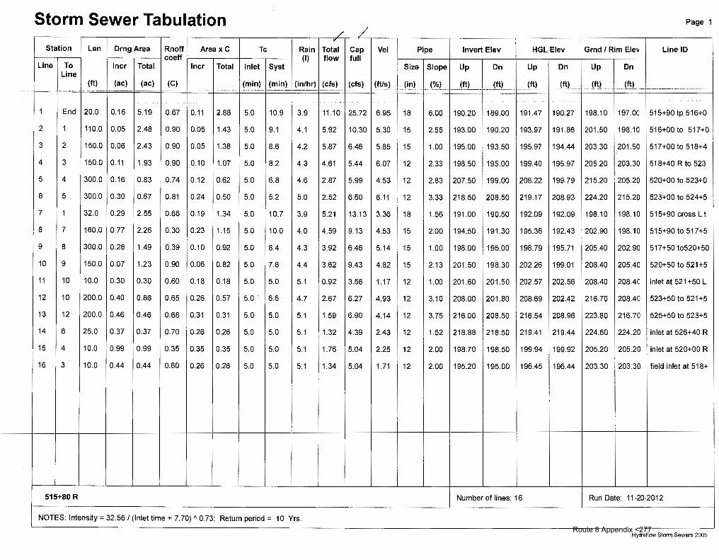
Storm Sewer Tabulation Page 1
Station Len OrngArea Rnoff Areax C Tc Rain Total Cap Vel Pipe Invert Elev HGL Elev Grnd I Rim Elev Line 10 coeff (I) flow full
Line To I ncr Total I ncr Total Inlet Syst Line
Size Slope Up On Up On Up On
(ft) (ac) (ac) (C) (min) (min) (in/hr) (cfs) (cfs) (ft/s) (in) (%) __ !!!L __ ___ JttL ... _ __ tttL _ ___ 1!!L _ __ !ttL __ __ jft) --- ---------··-·--·-·---··· ·- ·---- ----··. --- ·- --------·· ·--. ·-· --
1 End 20.0 0.16 5.19 0.67 0.11 2.88 5.0 10.9 3.9 11.10 25.72 6.95 18 6.00 190.20 189.00 191.47 190.27 198.10 197.oa 515+90 tp 516+0
2 1 110.0 0.05 2.48 0.90 0.05 1.43 5.0 9.1 4.1 5.92 10.30 5.30 15 2.55 193.00 190.20 193.97 191.86 201.50 198.1 a 516+00 to 517+0
3 2 150.0 0.06 2.43 0.90 0.05 1.38 5.0 8.6 4.2 5.87 6.46 5.85 15 1.00 195.00 193.50 195.97 194.44 203.30 201.5a 517+00 to 518+4
4 3 150.0 0.11 1.93 0.90 0.10 1.07 5.0 8.2 4.3 4.61 5.44 6.07 12 2.33 198.50 195.00 199.40 195.97 205.20 203.3a 518+40 R to 523
5 4 300.0 0.16 0.83 0.74 0.12 0.62 5.0 6.8 4.6 2.87 5.99 4.53 12 2.83 207.50 199.00 208.22 199.79 215.20 205.2a 520+00 to 523+0
6 5 300.0 0.30 0.67 0.81 0.24 0.50 5.0 5.2 5.0 2.52 6.50 6.11 12 3.33 218.50 208.50 219.17 208.93 224.20 215.2a 523+00 to 524+5
7 1 32.0 0.29 2.55 0.66 0.19 1.34 5.0 10.7 3.9 5.21 13.13 3.36 18 1.56 191.00 190.50 192.09 192.09 198.10 198.1 a 515+90 cross L t
8 7 160.0 0.77 2.26 0.30 0.23 1.15 5.0 10.0 4.0 4.59 9.13 4.53 15 2.00 194.50 191.30 195.36 192.43 202.90 198.1 a 515+90 to 517+5
9 8 300.0 0.26 1.49 0.39 0.10 0.92 5.0 8.4 4.3 3.92 6.46 5.14 15 1.00 198.00 195.00 198.79 195.71 205.40 202.9a 517+50to520+50
10 9 150.0 0.07 1.23 0.90 0.06 0.82 5.0 7.6 4.4 3.62 9.43 4.82 15 2.13 201.50 198.30 202.26 199.01 208.40 205.4a 520+50 to 521+5
11 10 10.0 0.30 0.30 0.60 0.18 0.18 5.0 5.0 5.1 0.92 3.56 1.17 12 1.00 201.60 201.50 202.57 202.56 208.40 208.4a inlet at 521 +50 L
12 10 200.0 0.40 0.86 0.65 0.26 0.57 5.0. 6.6 4.7 2.67 6.27 4.93 12 3.10 208.00 201.80 208.69 202.42 216.70 208.4a 523+50 to 521+5
13 12 200.0 0.46 0.46 0.68 0.31 0.31 5.0 5.0 5.1 1.59 6.90 4.14 12 3.75 216.00 208.50 216.54 208.96 223.80 216.7a 525+50 to 523+5
14 6 25.0 0.37 0.37 0.70 0.26 0.26 5.0 5.0 5.1 1.32 4.39 2.43 12 1.52 218.88 218.50 219.41 219.44 224.60 224.2a inlet at 526+40 R
15 4 10.0 0.99 0.99 0.35 0.35 0.35 5.0 5.0 5.1 1.76 5.04 2.25 12 2.00 198.70 198.50 199.94 199.92 205.20 205.2a inlet at 520+00 R
16 3 10.0 0.44 0.44 0.60 0.26 0.26 5.0 5.0 5.1 1.34 5.04 1.71 12 2.00 195.20 195.00 196.45 196.44 203.30 203.3a field inlet at 518+
+---
515+80 R Number of lines: 16 Run Date: 11-20-2012
NOTES: Intensity= 32.56/ (Inlet time+ 7.70) "0.73; Return period= 10 Yrs. --- ---- --
Hydraflow Storm Sewers 2005 Route 8 Appendix <277

Inlet Report Page 1
"V
Line Inlet ID Q= Q Q Q June Curb Inlet Grate Inlet Gutter Inlet Byp No CIA carry capt byp type line
Ht L area L w So w Sw Sx n Depth Spread Depth Spread Depr No (cfs) (cfs) (cfs) (cfs) (in) (ft) (sqft) (ft) (ft) (ft/ft) (ft) (ft/ft) (ft/ft) (ft) (ft) (ft) (ft) (in)
-·---·-- -~- - ---·-····-·------··---·- ·--··----------- -- . --·--------~ ----·----~ --·-···-·------- ·------- ---- ------------- ---·····----·-·· ------- --- ----------- --------- ------~ -~----- ----~----·- -------- ---------- ---------- -----~---- --~----·····---- ------------- -- ·--------- --·-------.
1 515+90 R 0.55 0.00 0.13 0.41 Curb 6.0 1.50 0.00 0:00 0.00 0.032 5.00 0.060 0.030 0.013 0.13 2.17 0.13 2.08 2.00 Off
2 517+00R 0.23 0.00 0.23 0.00 Grate 0.0 0.00 0.00 2.00 2.00 0.032 5.00 0.060 0.030 0.013 0.10 1.67 0.09 1.84 1.00 1
3 518+40 R 0.27 0.00 0.27 0.00 Grate 0.0 0.00 0.00 2.00 2.00 0.011 5.00 0.060 0.030 0.013 0.13 2.17 0.11 2.40 1.00 2
4 520+00 R 0.50 0.00 0.50 0.00 Grate 0.0 0.00 0.00 2.00 2.00 0.011 5.00 0.060 0.030 0.013 0.16 2.67 0.14 3.00 1.00 3
5 523+00 R 0.60 0.00 0.60 0.00 Grate 0.0 0.00 0.00 2.00 2.00 0.025 5.00 0.060 0.030 0.013 0.15 2.50 0.13 2.74 1.00 4
6 524+50 R 1.24 0.00 1.24 0.00 Grate 0.0 0.00 0.00 2.00 2.00 0.044 5.00 0.060 0.030 0.013 0.17 2.83 0.15 3.24 1.00 5
7 515+90 L 0.97 1.27 2.25 0.00 Grate 0.0 0.00 0.00 2.00 2.00 0.032 5.00 0.060 0.030 0.013 0.22 3.67 0.20 4.29 1.00 Off
8 517+50L 1.18 0.34 0.25 1.27 Curb 6.5 1.50 0.00 0.00 0.00 0.032 5.00 0.060 0.030 0.013 0.19 3.17 0.19 3.06 2.00 7
9 520+50 L 0.52 0.00 0.17 0.34 Curb 6.5 1.50 0.00 0.00 0.00 0.011 5.00 0.060 0.030 0.013 0.16 2.67 0.16 2.49 2.00 8
10 521+50 L 0.32 0.00 0.32 0.00 Grate 0.0 0.00 0.00 2.00 2.00 0.025 5.00 0.060 0.030 0.013 0.12 2.00 0.10 2.19 1.00 9
11 521 +50 L field 0.92 0.00 0.92 0.00 Grate 0.0 0.00 0.00 2.00 2.00 0.025 5.00 0.060 0.030 0.013 0.17 2.83 0.15 3.21 1.00 10
12 523+50 L 1.32 1.33 2.66 0.00 Grate 0.0 0.00 0.00 2.00 2.00 0.062 5.00 0.060 0.030 0.013 0.21 3.50 0.19 4.05 1.00 10
13 525+50 L 1.59 0.00 0.26 1.33 Curb 6.5 1.50 0.00 0.00 0.00 0.030 5.00 0.060 0.030 0.013 0.20 3.33 0.20 3.16 2.00 12
14 526+40 R 1.32 0.00 1.32 0.00 Grate 0.0 0.00 0.00 2.00 2.00 0.011 5.00 0.060 0.030 0.013 0.22 3.67 0.20 4.31 1.00 6
15 520+00 R 1.76 0.00 1.76 0.00 Grate 0.0 0.00 0.60 2.00 2.00 Sag 5.00 0.060 0.030 0.000 0.37 7.22 0.30 7.22 1.00 Off
16 518+40 1.34 0.00 1.34 0.00 Grate 0.0 0.00 0.46 2.00 2.00 Sag 5.00 0.060 0.030 0.000 0.37 7.22 0.30 7.22 1.00 Off
1' 'f Q/( oK'.
-
-
515+80 R 1 Number of lines: 16 I Run Date: 11-20-2012
NOTES: Inlet N-Values = 0.016; Intensity= 32.56/ (Inlet time+ 7.70) A 0.73; Return period= 10 Yrs.; *Indicates Known Q added
Hydraflow Storm Sewers 2005 Route 8 Appendix <278