fimac - cordis.europa.eu · (6.1) final numerical tool and (6.2) ... (figure 1). the pim was...
TRANSCRIPT
FIMAC Fast Impact Cross-Analysis Methodology for Composite Leading Edge Structures State of the Art – Background The aerospace community is challenged with how to evaluate the extent of impact damage due to foreign object impact (FOD), from tool drop, hailstone, runway debris, and bird strikes without resorting to exhaustive use of heavy numerical modeling tools and existing software. Extensive work was done by the aerospace research community, software producers, industry, and Government to devise analytical methods to evaluate impact damage on composite structures that can satisfy the certification requirements of modern air transportation systems. During the efforts of this work, the development of an integrated numerical and test approach for composite wing leading edge hailstone impact with electrical ice protection system was accomplished. The work was divided into testing of a building block of coupons, flat and curved panels, and wing leading edge with deicer and heating and the simulation which accurately modeled the tested structures. A validated tool was developed to determine wing leading edge ice impact damage and survivability. In the end a high-fidelity numerical GENOA-LSDYNA FEA model was developed for composite leading edge structures impacted by hail. Predictions were validated with test data and provided impact response database to compliment the experimental validation. The numerical model captured damage not seen during visual inspection which gave insight to heating element damage and effect on heating capabilities. This could help facilitated inspection and maintenance of critical areas for prolonged operational safety. Objectives The accomplished goals of the project were to develop and validate new and faster impact analysis models for LES, which overcome the drawbacks of the fine 3D spatial finite element discretization and time integration involved in present FE impact models. The main innovation of the project lies on the development of new types of integrated finite-element free fast impact models which physically satisfy the governing equations of impact mechanics, and their accuracy and predictive capability were validated and improved by cross-correlations of data from a series of tests organized in a building block
approach. Two types of impact models developed (1) A fast phenomenological semi-analytical impact model (SAIM) and (2) a reduced phenomenological impact model (PIM) which estimated force time response of impacted structures and were used in subsequent numerical simulations. The models were integrated with well-established and verified material characterization and qualification software and multi-scale progressive failure dynamic analysis (PFDA) capabilities, to characterize the impact resistance of composite structures and to determine: type of failure (delamination, crippling, etc.), damage footprint (which ply, length and width), energy absorbed during impact and post-impact residual strength and stiffness in tension (TAI), compression (CIA) and shear (SAI), and the post-impact thermal performance of the heater and remaining deicing functionality. All models accounted for temperature and moisture effects and were suitable for traditional and hybrid composite materials. The main objectives of the work are defined by the six work packages proposed: WP1: Definitions and Specifications which produced Deliverables (1.1) Report on Test Bench and Numerical Tool Specifications. WP2: Impact Modeling Tool Development which produced Deliverables (2.1) 1st Release of Numerical Tool Validated Against Numerical Results. WP3: Building Block Test Program produced Deliverables (3.1) Report on Impact Test-Bench. WP4: Impact Test-Bench Development which produced Deliverables (4.1) First issue of impact test bench, (4.2) Delivery of all specimen, and (4.3) Material Characterization. WP5: Preliminary Tool Validation which produced Deliverables (5.1) 2nd release of the Numerical Tool and (5.2) Final impact test bench. WP6: Total Tests Plan And Completion Of The Numerical Tool which produced Deliverables of the (6.1) final numerical tool and (6.2) report on conclusions and recommendations. Description of work Deliverable 1.1: Report on Test Bench and Numerical Tool Specifications. This deliverable defined the requirements for the anticipated analysis software, the impact testing, and the specifications for the materials, specimens and LES component. Bibliographic reviews were
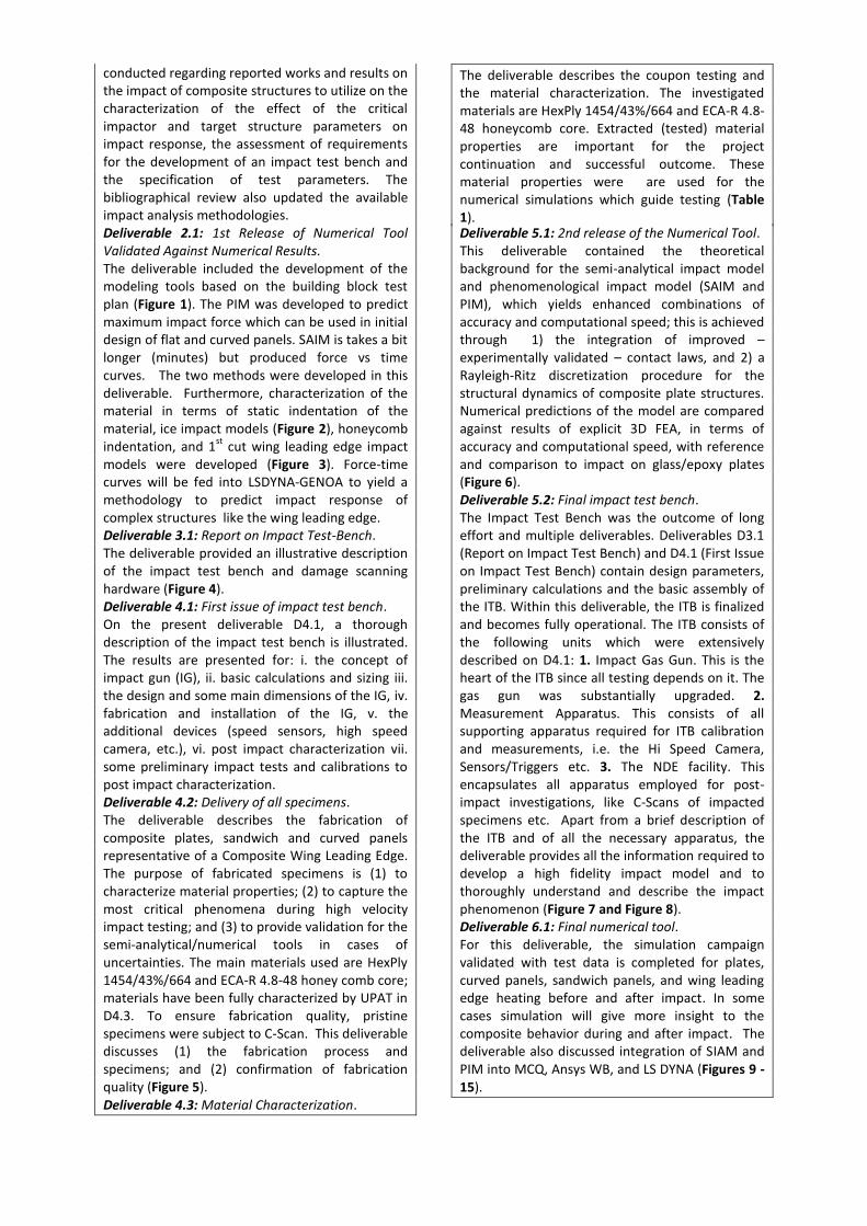
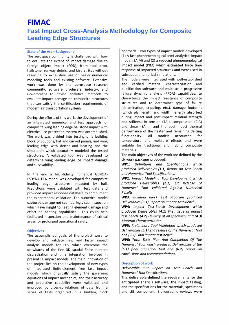
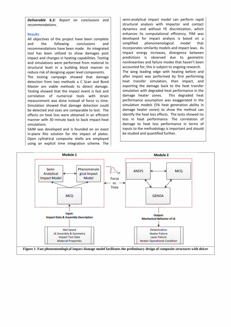
conducted regarding reported works and results on the impact of composite structures to utilize on the characterization of the effect of the critical impactor and target structure parameters on impact response, the assessment of requirements for the development of an impact test bench and the specification of test parameters. The bibliographical review also updated the available impact analysis methodologies. Deliverable 2.1: 1st Release of Numerical Tool Validated Against Numerical Results. The deliverable included the development of the modeling tools based on the building block test plan (Figure 1). The PIM was developed to predict maximum impact force which can be used in initial design of flat and curved panels. SAIM is takes a bit longer (minutes) but produced force vs time curves. The two methods were developed in this deliverable. Furthermore, characterization of the material in terms of static indentation of the material, ice impact models (Figure 2), honeycomb indentation, and 1
st cut wing leading edge impact
models were developed (Figure 3). Force-time curves will be fed into LSDYNA-GENOA to yield a methodology to predict impact response of complex structures like the wing leading edge. Deliverable 3.1: Report on Impact Test-Bench. The deliverable provided an illustrative description of the impact test bench and damage scanning hardware (Figure 4). Deliverable 4.1: First issue of impact test bench. On the present deliverable D4.1, a thorough description of the impact test bench is illustrated. The results are presented for: i. the concept of impact gun (IG), ii. basic calculations and sizing iii. the design and some main dimensions of the IG, iv. fabrication and installation of the IG, v. the additional devices (speed sensors, high speed camera, etc.), vi. post impact characterization vii. some preliminary impact tests and calibrations to post impact characterization. Deliverable 4.2: Delivery of all specimens. The deliverable describes the fabrication of composite plates, sandwich and curved panels representative of a Composite Wing Leading Edge. The purpose of fabricated specimens is (1) to characterize material properties; (2) to capture the most critical phenomena during high velocity impact testing; and (3) to provide validation for the semi-analytical/numerical tools in cases of uncertainties. The main materials used are HexPly 1454/43%/664 and ECA-R 4.8-48 honey comb core; materials have been fully characterized by UPAT in D4.3. To ensure fabrication quality, pristine specimens were subject to C-Scan. This deliverable discusses (1) the fabrication process and specimens; and (2) confirmation of fabrication quality (Figure 5). Deliverable 4.3: Material Characterization.
The deliverable describes the coupon testing and the material characterization. The investigated materials are HexPly 1454/43%/664 and ECA-R 4.8-48 honeycomb core. Extracted (tested) material properties are important for the project continuation and successful outcome. These material properties were are used for the numerical simulations which guide testing (Table 1). Deliverable 5.1: 2nd release of the Numerical Tool. This deliverable contained the theoretical background for the semi-analytical impact model and phenomenological impact model (SAIM and PIM), which yields enhanced combinations of accuracy and computational speed; this is achieved through 1) the integration of improved – experimentally validated – contact laws, and 2) a Rayleigh-Ritz discretization procedure for the structural dynamics of composite plate structures. Numerical predictions of the model are compared against results of explicit 3D FEA, in terms of accuracy and computational speed, with reference and comparison to impact on glass/epoxy plates (Figure 6). Deliverable 5.2: Final impact test bench. The Impact Test Bench was the outcome of long effort and multiple deliverables. Deliverables D3.1 (Report on Impact Test Bench) and D4.1 (First Issue on Impact Test Bench) contain design parameters, preliminary calculations and the basic assembly of the ITB. Within this deliverable, the ITB is finalized and becomes fully operational. The ITB consists of the following units which were extensively described on D4.1: 1. Impact Gas Gun. This is the heart of the ITB since all testing depends on it. The gas gun was substantially upgraded. 2. Measurement Apparatus. This consists of all supporting apparatus required for ITB calibration and measurements, i.e. the Hi Speed Camera, Sensors/Triggers etc. 3. The NDE facility. This encapsulates all apparatus employed for post-impact investigations, like C-Scans of impacted specimens etc. Apart from a brief description of the ITB and of all the necessary apparatus, the deliverable provides all the information required to develop a high fidelity impact model and to thoroughly understand and describe the impact phenomenon (Figure 7 and Figure 8). Deliverable 6.1: Final numerical tool. For this deliverable, the simulation campaign validated with test data is completed for plates, curved panels, sandwich panels, and wing leading edge heating before and after impact. In some cases simulation will give more insight to the composite behavior during and after impact. The deliverable also discussed integration of SIAM and PIM into MCQ, Ansys WB, and LS DYNA (Figures 9 - 15).
Deliverable 6.2: Report on conclusions and recommendations. Results All objectives of the project have been complete and the following conclusions and recommendations have been made. An integrated tool has been utilized to show damages post impact and changes in heating capabilities. Testing and simulations were performed from material to structural level in a building block manner to reduce risk of designing upper level components. The testing campaign showed that damage detection from two methods a C Scan and Bond Master are viable methods to detect damage. Testing showed that the impact event is fast and correlation of numerical tools with strain measurement was done instead of force vs time. Simulation showed that damage detection could be detected and sizes are comparable to test. The effects on heat loss were obtained in an efficient manner with 30 minute back to back impact-heat simulations. SAIM was developed and is founded on an exact in-plane Ritz solution for the impact of plates. Open cylindrical composite shells are employed using an explicit time integration scheme. The
semi-analytical impact model can perform rapid structural analysis with impactor and contact dynamics and without FE discretization, which enhances its computational efficiency. PIM was developed for impact analysis is based on a simplified phenomenological model that incorporates similarity models and impact laws. As impact energy increases, divergence between predictions is observed due to geometric nonlinearities and failure modes that haven’t been accounted for; this is subject to ongoing research. The wing leading edge with heating before and after impact was performed by first performing heat transfer simulation, then impact, and exporting the damage back to the heat transfer simulation with degraded heat performance in the damage heater zones. This degraded heat performance assumption was exaggerated in the simulation models (5% heat generation ability in damage heater zones) to show the method can identify the heat loss effects. The tests showed no loss in heat performance. The correlation of damage to heat loss performance in terms of inputs to the methodology is important and should be studied and quantified further.
Figure 1. Fast phenomenological impact damage model facilitates the preliminary design of composite structures with deicer
Figure 2. Verification of ice impact load displacement for Lagrangian, SPH, and Eulerian models
Figure 3. WLE Initial Impact Models
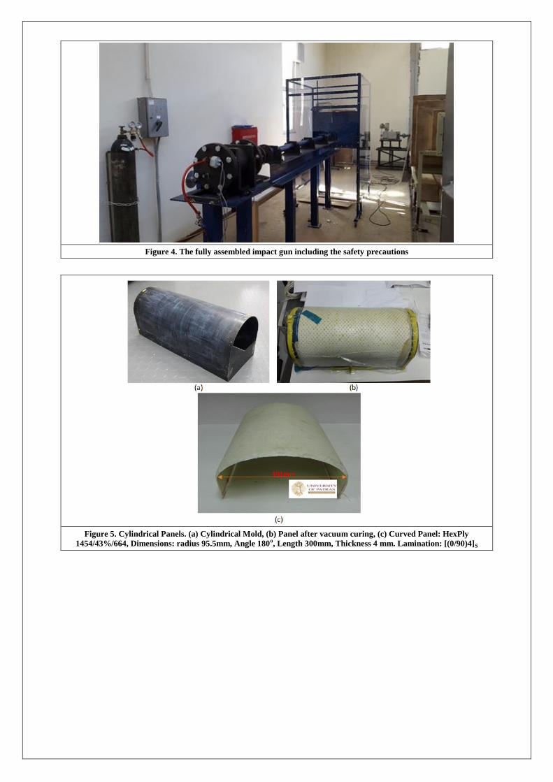
Figure 4. The fully assembled impact gun including the safety precautions
Figure 5. Cylindrical Panels. (a) Cylindrical Mold, (b) Panel after vacuum curing, (c) Curved Panel: HexPly
1454/43%/664, Dimensions: radius 95.5mm, Angle 180o, Length 300mm, Thickness 4 mm. Lamination: [(0/90)4]S
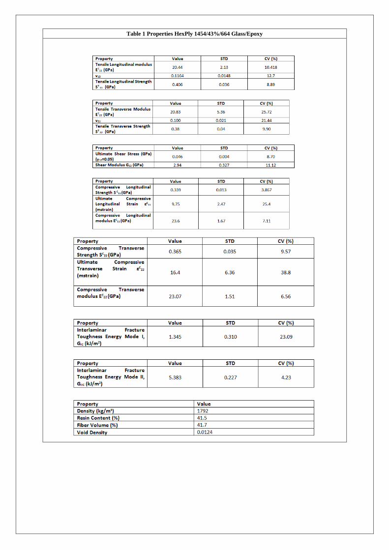
Table 1 Properties HexPly 1454/43%/664 Glass/Epoxy
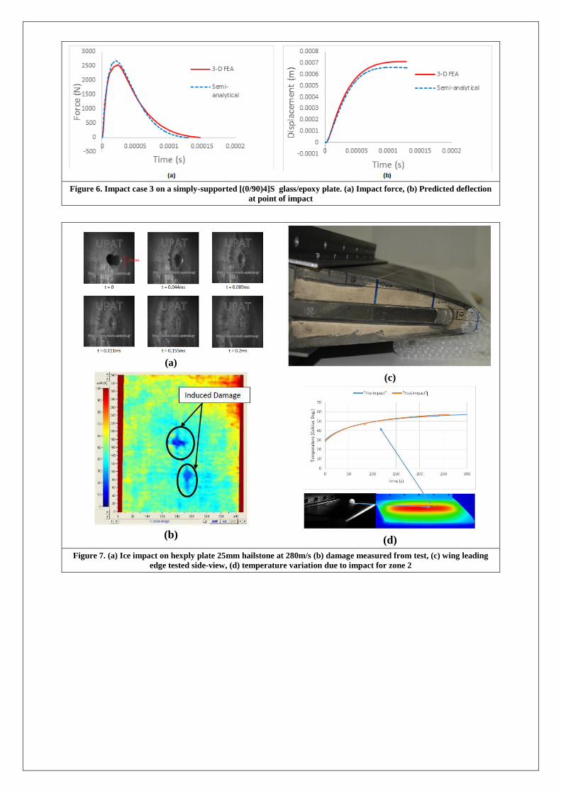
Figure 6. Impact case 3 on a simply-supported [(0/90)4]S glass/epoxy plate. (a) Impact force, (b) Predicted deflection
at point of impact
(a)
(b)
(c)
(d)
Figure 7. (a) Ice impact on hexply plate 25mm hailstone at 280m/s (b) damage measured from test, (c) wing leading
edge tested side-view, (d) temperature variation due to impact for zone 2
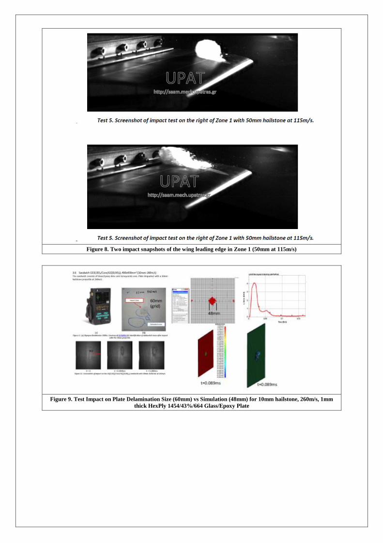
Figure 8. Two impact snapshots of the wing leading edge in Zone 1 (50mm at 115m/s)
Figure 9. Test Impact on Plate Delamination Size (60mm) vs Simulation (48mm) for 10mm hailstone, 260m/s, 1mm
thick HexPly 1454/43%/664 Glass/Epoxy Plate
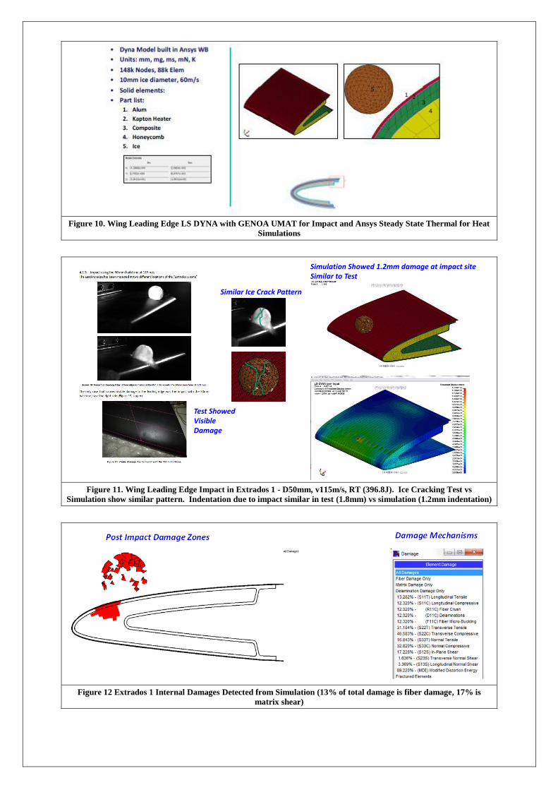
Figure 10. Wing Leading Edge LS DYNA with GENOA UMAT for Impact and Ansys Steady State Thermal for Heat
Simulations
Figure 11. Wing Leading Edge Impact in Extrados 1 - D50mm, v115m/s, RT (396.8J). Ice Cracking Test vs
Simulation show similar pattern. Indentation due to impact similar in test (1.8mm) vs simulation (1.2mm indentation)
Figure 12 Extrados 1 Internal Damages Detected from Simulation (13% of total damage is fiber damage, 17% is
matrix shear)
Test Showed Visible Damage
Simulation Showed 1.2mm damage at impact siteSimilar to Test
Similar Ice Crack Pattern
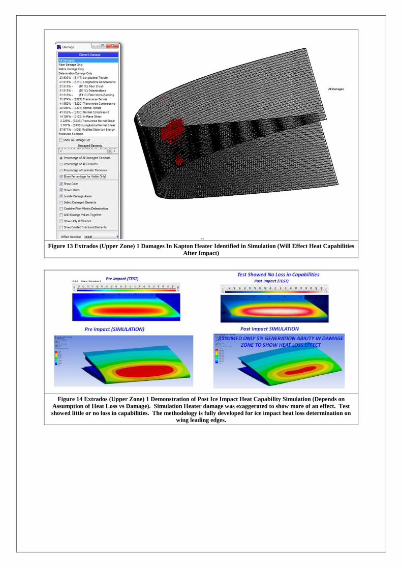
Figure 13 Extrados (Upper Zone) 1 Damages In Kapton Heater Identified in Simulation (Will Effect Heat Capabilities
After Impact)
Figure 14 Extrados (Upper Zone) 1 Demonstration of Post Ice Impact Heat Capability Simulation (Depends on
Assumption of Heat Loss vs Damage). Simulation Heater damage was exaggerated to show more of an effect. Test
showed little or no loss in capabilities. The methodology is fully developed for ice impact heat loss determination on
wing leading edges.
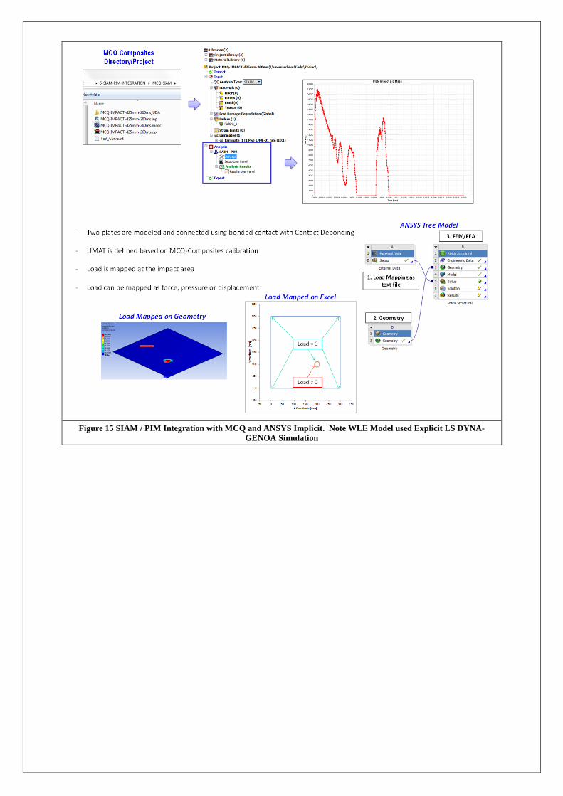
Figure 15 SIAM / PIM Integration with MCQ and ANSYS Implicit. Note WLE Model used Explicit LS DYNA-
GENOA Simulation
Project Summary
Acronym: FIMAC
Name of proposal: Fast Impact Cross-Analysis Methodology for Composite Leading Edge Structures
Technical domain: Engineering
Involved ITD: SGO
Grant Agreement: SP1-JTI-CS-2013-02-SGO-02-073
Instrument: Clean Sky JU
Total Cost: 500000€
Clean Sky contribution: 375000€
Call: SP1-JTI-CS-2013-02
Starting date: Nov 1st, 2014
Ending date: Nov 1st, 2016
Duration: 24 months
Coordinator contact details: Vinicio Salvi
Via Antonio Silvani 118 118
Roma, Italy 00139
Project Officer: Antonio Vecchio
Participating members: Alpha Consulting Services, Rome, Italy
University of Patras (UPAT), Patras, Greece
Godinho Luz Engineering (GLE), Libson, Portugal
Zodiac Aerospace, Caudebec Les Elbeufs, France