fim avionics technical reference manual - nasa · pdf filefim avionics technical reference...
TRANSCRIPT
July 2017
NASA/CR-2017-219646
FIM Avionics Technical Reference Manual Craig Schimmel Honeywell International, Inc., Temple, Arizona
https://ntrs.nasa.gov/search.jsp?R=20170007241 2018-05-17T17:56:31+00:00Z

NASA STI Program . . . in Profile
Since its founding, NASA has been dedicated to the advancement of aeronautics and space science. The NASA scientific and technical information (STI) program plays a key part in helping NASA maintain this important role.
The NASA STI program operates under the auspices of the Agency Chief Information Officer. It collects, organizes, provides for archiving, and disseminates NASA’s STI. The NASA STI program provides access to the NTRS Registered and its public interface, the NASA Technical Reports Server, thus providing one of the largest collections of aeronautical and space science STI in the world. Results are published in both non-NASA channels and by NASA in the NASA STI Report Series, which includes the following report types:
• TECHNICAL PUBLICATION. Reports of
completed research or a major significant phase of research that present the results of NASA Programs and include extensive data or theoretical analysis. Includes compilations of significant scientific and technical data and information deemed to be of continuing reference value. NASA counter-part of peer-reviewed formal professional papers but has less stringent limitations on manuscript length and extent of graphic presentations.
• TECHNICAL MEMORANDUM. Scientific and technical findings that are preliminary or of specialized interest, e.g., quick release reports, working papers, and bibliographies that contain minimal annotation. Does not contain extensive analysis.
• CONTRACTOR REPORT. Scientific and technical findings by NASA-sponsored contractors and grantees.
• CONFERENCE PUBLICATION. Collected papers from scientific and technical conferences, symposia, seminars, or other meetings sponsored or co-sponsored by NASA.
• SPECIAL PUBLICATION. Scientific, technical, or historical information from NASA programs, projects, and missions, often concerned with subjects having substantial public interest.
• TECHNICAL TRANSLATION. English-language translations of foreign scientific and technical material pertinent to NASA’s mission.
Specialized services also include organizing and publishing research results, distributing specialized research announcements and feeds, providing information desk and personal search support, and enabling data exchange services.
For more information about the NASA STI program, see the following:
• Access the NASA STI program home page at
http://www.sti.nasa.gov
• E-mail your question to [email protected]
• Phone the NASA STI Information Desk at 757-864-9658
• Write to: NASA STI Information Desk Mail Stop 148 NASA Langley Research Center Hampton, VA 23681-2199

National Aeronautics and Space Administration Langley Research Center Prepared for Langley Research Center Hampton, Virginia 23681-2199 under Contract NNL13AA03B, NNL15AB46T
July 2017
NASA/CR-2017-219646
FIM Avionics Technical Reference Manual Craig Schimmel Honeywell International, Inc., Temple, Arizona

Available from:
NASA STI Program / Mail Stop 148
NASA Langley Research Center
Hampton, VA 23681-2199
Fax: 757-864-6500
The use of trademarks or names of manufacturers in this report is for accurate reporting and does not
constitute an official endorsement, either expressed or implied, of such products or manufacturers by the
National Aeronautics and Space Administration.

i
ADVANCED TECHNOLOGY
Document / Data Item Approval Sheet
TITLE: FIM Avionics Technical Reference Manual
DATA ITEM: EG-003690-6.15
Deliverable Number: 6.15
APPROVALS DATE SIGNATURE
PREPARED BY Craig Schimmel
Craig Schimmel
PROGRAM MANAGEMENT Rick Berckefeldt
Rick Berckefeldt
PROJECT ENGINEER Jack Rahn
Jack Rahn
SYSTEMS ENGINEER Bill True
Bill True
ii
DELIVERABLE 6.15: FIM AVIONICS TECHNICAL REFERENCE MANUAL
FOR BOEING RESEARCH AND TECHNOLOGY
AGREEMENT NO: LETTER CONTRACT 1099212 DATED JUNE 15, 2015
IN SUPPORT OF NASA ATD-1 PRIME CONTRACT NNL13AA03B
REV B
8 MARCH 2017
PREPARED BY: HONEYWELL INTERNATIONAL, INC. AEROSPACE – DEFENSE & SPACE
1300 W. WARNER ROAD TEMPE, AZ 85285
CAGE 59364
DOCUMENT NUMBER: EG-003690-6.15

Use or disclosure of data contained on this sheet is subject to the restrictions on the title page of this document. i
REVISION HISTORY
Rev Date Revision Summary — 1-Dec-16 Initial version A 7 Mar 17 Updates per customer comments
- Updated diagrams and text to match SDD updates - Text and formatting corrections - Attached latest Speed Control source code (may be
delivered in separate zip file) B 8 Mar 17 Removed title page footer

Use or disclosure of data contained on this sheet is subject to the restrictions on the title page of this document. ii
TABLE OF CONTENTS
1.0 INTRODUCTION ............................................................................................................... 1 1.1 System Overview ................................................................................................... 1 1.2 Document Overview ............................................................................................... 1
2.0 REFERENCED DOCUMENTS .......................................................................................... 1 2.1 Customer Documents ............................................................................................. 1 2.2 Honeywell Documents ............................................................................................ 1 2.3 Other Documents ................................................................................................... 1
3.0 FIM AVIONICS TECHNICAL REFERENCE ...................................................................... 3 3.1 Theory of Operation ................................................................................................ 3
3.1.1 FIM Application launch and initialization ................................................. 5 3.1.2 FIM Application Installation and Directories ............................................ 5 3.1.3 FIM Application Configuration ................................................................. 7 3.1.4 FIM Host ............................................................................................... 10 3.1.5 Trajectory Generator ............................................................................. 21 3.1.6 Speed Control ....................................................................................... 24 3.1.7 Navigation Database ............................................................................ 28 3.1.8 Field Upgrades – FIM Host Application ................................................. 28 3.1.9 Field Upgrades – Traffic Computer ....................................................... 29 3.1.10 TCAS / FIM coexistence ....................................................................... 29
3.2 FIM Application Software Architecture Description ............................................... 29 3.2.1 Resource Requirements ....................................................................... 29 3.2.2 FIM Application Architecture ................................................................. 30 3.3.2 Data Logging ........................................................................................ 61
3.4 Interface Control Specifications ............................................................................ 64 3.4.1 TPU to FIM Avionics ICD ...................................................................... 64 3.4.2 TPU Dependency ................................................................................. 64
4.0 SAMPLE FILES ............................................................................................................... 71 4.1 Sample FIM Host Configuration Files ................................................................... 71
4.1.1 ConfigIM.conf Sample........................................................................... 71 4.1.2 EFBCom.conf ....................................................................................... 72 4.1.3 StapLabelChannel.conf ......................................................................... 72
5.0 DATA LOGGING VALUES.............................................................................................. 74
6.0 SPEED CONTROL SOURCE ........................................................................................ 118
7.0 ACRONYMS .................................................................................................................. 119

Use or disclosure of data contained on this sheet is subject to the restrictions on the title page of this document. 1
1.0 INTRODUCTION
1.1 System Overview The objective of this program is to design and develop two prototype FIM avionics systems that can be installed in the following aircraft: B737-NG, B757-200. The FIM avionics system shall host a FIM application based on NASA’s ASTAR algorithm.
1.2 Document Overview This document contains a summary of technical information relating to the Honeywell FIM software, TPU and system operation. 2.0 REFERENCED DOCUMENTS The following documents apply to the extent to which they are referenced within this plan 2.1 Customer Documents Document Number Document Title CR-2015-218794
Honeywell_SOW_ATD1_Phase2_REV B.docx NASA ASTAR 13 rev. 7 description document
2.2 Honeywell Documents Document Number Document Title EG-003690-6.3.D EG-003690-6.3.C
Software Design Description for the FIM software FIM Software Requirements Specification
EG-003690-6.7 EG-003690-6.20 EG-003690-6.22 XCRIBE D201404000021
Honeywell Inputs for the System Requirements Definition Document Ground Test Plan Test Aircraft Installation Plan Honeywell XCRIBE Programming Manual Maintenance Manual, TPA-100B TCAS Processor
2.3 Other Documents Document Number Document Title

Use or disclosure of data contained on this sheet is subject to the restrictions on the title page of this document. 2
ATD1_FIMSRD_2015-01-23 Flight Deck Interval Management (FIM) System Requirements Document (SRD)
D06412904 Rev. B D06415030 Rev. B 8725G1 ARINC 834
G700AB Software Design Guide ICD For the Smart Display Unit Specification Control Drawing for the Smart Display EFB Aircraft Data Interface Function (ADIF)

Use or disclosure of data contained on this sheet is subject to the restrictions on the title page of this document. 3
3.0 FIM AVIONICS TECHNICAL REFERENCE
The technical reference document provides an overview of the technical design, operation and performance of the FIM application and FIM avionics system
3.1 Theory of Operation
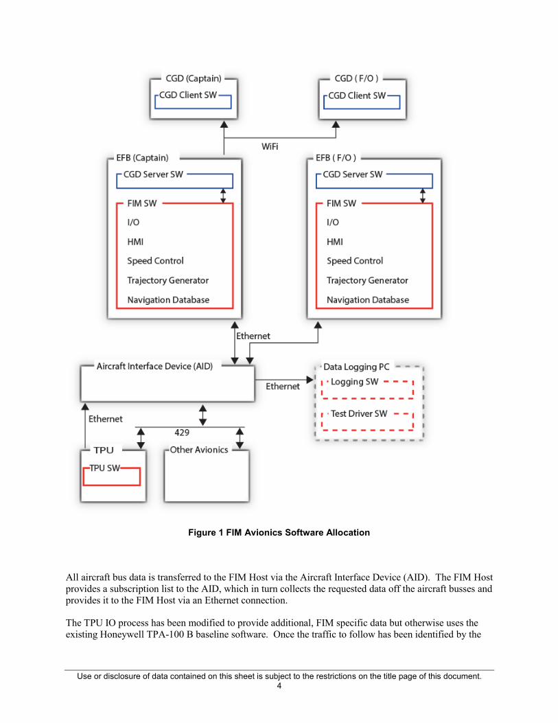
The EFB FIM software is comprised of the FIMHost.exe application and the CGD Server. The FIM Host implements the CDTI, FIM IO, Speed Control, Trajectory Generation, and Navigation Database Services. The CGD Server receives data from the FIM Host and transfers it to a web browser based application on the CGD hardware. Separate EFB and CGD are provided for the captain and first officer. The FIM Host software operates in a master-slave mode, with the captain’s EFB typically being the master. User input and current FIM state is shared between the master and slave, but only the master EFB performs the FIM computation.
Use or disclosure of data contained on this sheet is subject to the restrictions on the title page of this document. 4
Figure 1 FIM Avionics Software Allocation
All aircraft bus data is transferred to the FIM Host via the Aircraft Interface Device (AID). The FIM Host provides a subscription list to the AID, which in turn collects the requested data off the aircraft busses and provides it to the FIM Host via an Ethernet connection.
The TPU IO process has been modified to provide additional, FIM specific data but otherwise uses the existing Honeywell TPA-100 B baseline software. Once the traffic to follow has been identified by the

Use or disclosure of data contained on this sheet is subject to the restrictions on the title page of this document. 5
FIM Host software, the TPU will ensure the target data is provided in the DTIF traffic, even if it would have been normally prioritized out.
Data logging is performed off board, on a separate data logging laptop PC. The data logging system is based on the existing Honeywell MonTPA (Monitor TPA) logging software. In the case of MonTPA, the traffic computer sends data logging packets over Ethernet to the MonTPA logging software running on the laptop. The FIM Host software uses the same approach and logging packet structure, but connects to the MonEFB (Monitor EFB) logging software on the PC. MonEFB is a variant of MonTPA modified to parse and display the FIM specific log messages. Both MonTPA and MonEFB capture all received data in log files for post event analysis.
3.1.1 FIM Application launch and initialization
While the FIM application, FIMHost.exe, can be run directly by double clicking the executable on the EFB, a batch file on the EFB desktop sets up the networking parameters, runs the CGD server and the FIM host software. To start the EFB FIM software, double click the StartFIM.bat batch file. The FIM software will initialize per the configuration files, with only one EFB taking on the master role.
Figure 2 EFB Software Startup
The TPU is installed and starts up as in any other aircraft installation.
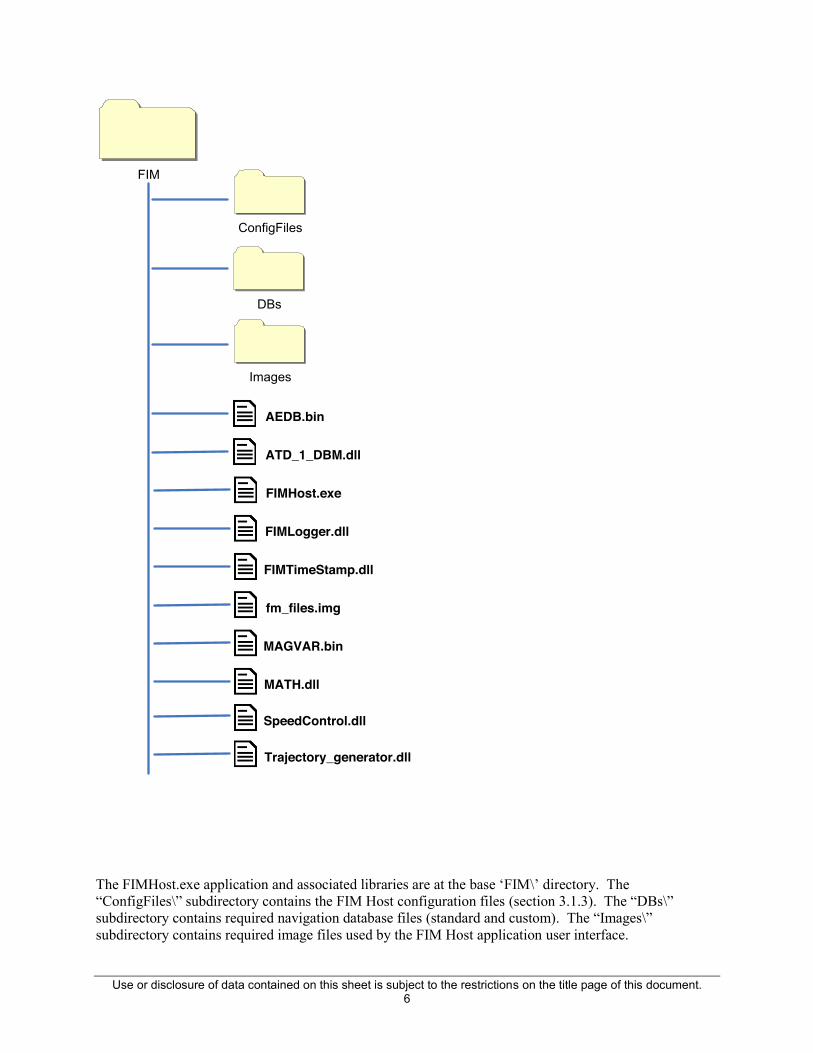
3.1.2 FIM Application Installation and Directories
The FIM Avionics EFB is a MS Windows based tablet. The FIM Application is installed in a subdirectory on the “C:” drive. The directory structure is shown:
Use or disclosure of data contained on this sheet is subject to the restrictions on the title page of this document. 6
ConfigFiles
FIM
DBs
Images
AEDB.bin
ATD_1_DBM.dll
FIMHost.exe
FIMLogger.dll
FIMTimeStamp.dll
fm_files.img
MAGVAR.bin
MATH.dll
SpeedControl.dll
Trajectory_generator.dll
The FIMHost.exe application and associated libraries are at the base ‘FIM\’ directory. The “ConfigFiles\” subdirectory contains the FIM Host configuration files (section 3.1.3). The “DBs\” subdirectory contains required navigation database files (standard and custom). The “Images\” subdirectory contains required image files used by the FIM Host application user interface.
Use or disclosure of data contained on this sheet is subject to the restrictions on the title page of this document. 7
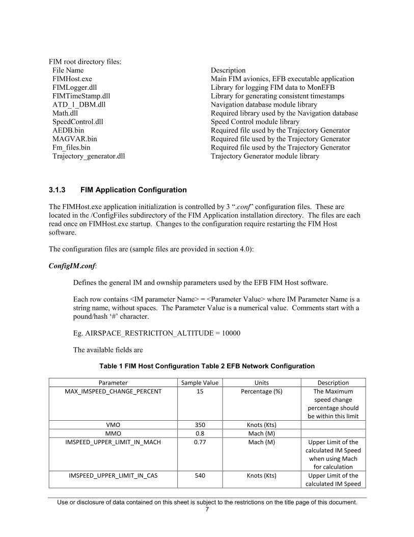
FIM root directory files: File Name Description FIMHost.exe Main FIM avionics, EFB executable application FIMLogger.dll Library for logging FIM data to MonEFB FIMTimeStamp.dll Library for generating consistent timestamps ATD_1_DBM.dll Navigation database module library Math.dll Required library used by the Navigation database SpeedControl.dll Speed Control module library AEDB.bin Required file used by the Trajectory Generator MAGVAR.bin Required file used by the Trajectory Generator Fm_files.bin Required file used by the Trajectory Generator Trajectory_generator.dll Trajectory Generator module library
3.1.3 FIM Application Configuration
The FIMHost.exe application initialization is controlled by 3 “.conf” configuration files. These are located in the /ConfigFiles subdirectory of the FIM Application installation directory. The files are each read once on FIMHost.exe startup. Changes to the configuration require restarting the FIM Host software.
The configuration files are (sample files are provided in section 4.0):
ConfigIM.conf:
Defines the general IM and ownship parameters used by the EFB FIM Host software.
Each row contains <IM parameter Name> = <Parameter Value> where IM Parameter Name is a string name, without spaces. The Parameter Value is a numerical value. Comments start with a pound/hash ‘#’ character.
Eg. AIRSPACE_RESTRICITON_ALTITUDE = 10000
The available fields are
Table 1 FIM Host Configuration Table 2 EFB Network Configuration
Parameter Sample Value Units Description MAX_IMSPEED_CHANGE_PERCENT 15 Percentage (%) The Maximum
speed change percentage should be within this limit
VMO 350 Knots (Kts) MMO 0.8 Mach (M)
IMSPEED_UPPER_LIMIT_IN_MACH 0.77 Mach (M) Upper Limit of the calculated IM Speed
when using Mach for calculation
IMSPEED_UPPER_LIMIT_IN_CAS 540 Knots (Kts) Upper Limit of the calculated IM Speed

Use or disclosure of data contained on this sheet is subject to the restrictions on the title page of this document. 8
when using CAS for calculation
IMSPEED_LOWER_LIMIT_IN_CAS 120 Knots (Kts) Lower Limit of the calculated IM Speed
when using CAS / Mach for calculation
MIN_FINAL_APPROACH_SPEED 120 Knots (Kts) Minimum Final Approach Speed of
the Aircraft HORIZONTAL_PATH_CONFORMANCE_LIMIT 3.0 Nautical Miles (NM) Maximum
Horizontal deviation from the Computed
Trajectory CRUISE_PROFILE_ALTITUDE_IN_FL 230 FL Cruise Profile
Altitude in terms of Flight Level
CRUISE_PROFILE_SPEED_IN_MACH 0.75 Mach (M) Cruise Profile Speed DESCENT_PROFILE_SPEED_IN_CAS 240 Knots (Kts) Descend Profile
Speed AIRSPACE_RESTRICTION_SPEED_IN_CAS 250 Knots (Kts) Airspace Speed
Restriction AIRSPACE_RESTRICTION_ALTITUDE 10000 Feet (ft) Airspace Restriction
Altitude FINAL_APPROACH_DELTA_ANGLE 45 Degrees Minimum Angle for
the Ownship or the Target for Final
Approach Clearance
EFBCom.conf:
Defines the EFB master, slave and observer IP communications addresses. Each configuration row contains <Label> _SPACE_ <IP Address>, where label provides the name of the remote connection. Comments start with a pound/hash ‘#’ character.
The valid labels are: Parameter Name Example IP Address Description
CAPTAINEFBIP 192.168.4.101 Master EFB FIRSTOFFICEREFBIP 192.168.4.102 Slave EFB
TESTDIRECTOREFBIP 192.168.4.103 Test Director EFB AIDUIP 192.168.4.254 Aircraft Interface Device
StapLableChannel.conf:

Use or disclosure of data contained on this sheet is subject to the restrictions on the title page of this document. 9
Defines which ARINC labels and channels that the AID will subscribe to, and transfer to the EFB using the STAP protocol. Each configuration row contains <Label> _SPACE_ <Channel #>. Comments start with a pound/hash ‘#’ character.
Table 3 STAP Label Configuration
Label No Channel No Description DTIF (Display of Traffic Information Files) Information
367 0 DTIF STX and ETX Labels 366 0 DTIF Data Labels
Ownship Information 110 0 GPS Latitude Coarse 111 0 GPS Longitude Coarse 120 0 GPS Latitude Fine 121 0 GPS Longitude Fine 203 0 Barometric Altitude 205 3 Mach 206 3 Calibrated Air Speed 213 3 Static Air Temperature 312 2 Ground Speed 313 2 True Track Angle 314 2 True Heading 315 2 Wind Speed 316 2 Wind Direction
Health Information 13 0 TCAS Display Control 15 0 TCAS Altitude Selection Limit
125 0 UTC Time HH:MM.M 140 0 UTC Time Seconds Fine 150 0 UTC Time HH:MM:SS 163 0 Availability of different application 270 0 Advisory 274 0 TCAS mode 350 0 TCAS System Health
Use or disclosure of data contained on this sheet is subject to the restrictions on the title page of this document. 10
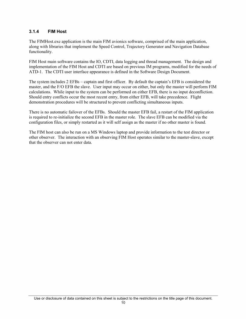
3.1.4 FIM Host
The FIMHost.exe application is the main FIM avionics software, comprised of the main application, along with libraries that implement the Speed Control, Trajectory Generator and Navigation Database functionality.
FIM Host main software contains the IO, CDTI, data logging and thread management. The design and implementation of the FIM Host and CDTI are based on previous IM programs, modified for the needs of ATD-1. The CDTI user interface appearance is defined in the Software Design Document.
The system includes 2 EFBs – captain and first officer. By default the captain’s EFB is considered the master, and the F/O EFB the slave. User input may occur on either, but only the master will perform FIM calculations. While input to the system can be performed on either EFB, there is no input deconfliction. Should entry conflicts occur the most recent entry, from either EFB, will take precedence. Flight demonstration procedures will be structured to prevent conflicting simultaneous inputs.
There is no automatic failover of the EFBs. Should the master EFB fail, a restart of the FIM application is required to re-initialize the second EFB in the master role. The slave EFB can be modified via the configuration files, or simply restarted as it will self assign as the master if no other master is found.
The FIM host can also be run on a MS Windows laptop and provide information to the test director or other observer. The interaction with an observing FIM Host operates similar to the master-slave, except that the observer can not enter data.

Use or disclosure of data contained on this sheet is subject to the restrictions on the title page of this document. 11
3.1.4.1 FIM Host State Flow
The FIM Host manages the FIM state flow within the FIM Avionics. The following describes the state flow architecture implemented in the FIM Host.
Enabling ARM: The operator enters the Own-ship information and the Target information.
The Airport is assumed to be the same for both ownship and target. The below flow diagram explains the enabling of ARM button to activate FIM (Flight-deck Interval Management)
Figure 3 ARM State Flow

Use or disclosure of data contained on this sheet is subject to the restrictions on the title page of this document. 12
General State Machine Execution:
State Machine
Ownship & Target Data
Speed Control & Trajectory
Data
Output State
Figure 4 General State Machine Flow
The State machine consumes the user input, ownship and target information, speed control output and trajectory output, validates the states and provides the state as output. The following State Machine flow is the high level view of the state machine, with detailed state flows following.

Use or disclosure of data contained on this sheet is subject to the restrictions on the title page of this document. 13
Figure 5 FIM State Machine Flow

Use or disclosure of data contained on this sheet is subject to the restrictions on the title page of this document. 14
Transition from ARMED to Other States: The flow diagram presents the possible transition from ARMED States.
Has Ownship crossed PTP?
ARMED State
NO
YES
OFF / TERMINATE State
Has Pilot Invoked “CANCEL IM”?
YES
Criteria Failed?
NO
UNABLE State YES
AVAILABLE State
NO
Criteria met for moving to
AVAILABLE State?YES
NO
Figure 6 ARMED State Transition

Use or disclosure of data contained on this sheet is subject to the restrictions on the title page of this document. 15
Transition from AVAILABLE to Other States: The flow diagram illustrates the possible transition from AVAILABLE States.
Has Ownship crossed PTP?
AVAILABLE State
NO
YES
OFF / TERMINATE State
Has Pilot Invoked “CANCEL IM”?
YES
Criteria Failed?
NO
UNABLE State YES
NO
Has Pilot Invoked “EXECUTE”?PAIRED State YESNO
ARMED State
Pilot Amended IM Clearance? Or Pilot Amended Ownship
Information? Or Criteria match for ARMED State?
NO
YES
Figure 7 AVAILABLE State Transition

Use or disclosure of data contained on this sheet is subject to the restrictions on the title page of this document. 16
Transition from PAIRED to Other States: The flow diagram shows the possible transition from PAIRED States.
Has Ownship crossed PTP?
PAIRED State
NO
YES
OFF / TERMINATE State
Has Pilot Invoked “CANCEL IM”?
YES
Criteria Failed?
NO
UNABLE State YES
NO
NO
ARMED State
Pilot Amended IM Clearance? Or Pilot Amended Ownship
Information?
NOYES
Pilot Initiated Suspend?
NO
SUSPEND AVAILABLE State YES
Criteria match for ARMED State?SUSPEND ARMED State YES
Figure 8 Paired State Transition

Use or disclosure of data contained on this sheet is subject to the restrictions on the title page of this document. 17
Transition from SUSPENDED AVAILABLE to Other States: The flow diagram shows the possible transition from SUSPENDED AVAILABLE States.
Has Ownship crossed PTP?
SUSPEND AVAILABLE State
NO
YES
OFF / TERMINATE State
Has Pilot Invoked “CANCEL IM”?
YES
Criteria Failed?
NO
UNABLE State YES
NO
NO
ARMED State
Pilot Amended IM Clearance? Or Pilot Amended Ownship
Information?
NOYES
Criteria match for SUSPENDED ARMED
State?
NO
SUSPEND ARMED State YES
Pilot Initiated Resume?PAIRED State YES
Figure 9 Suspend-Available State Transition

Use or disclosure of data contained on this sheet is subject to the restrictions on the title page of this document. 18
Transition from SUSPENDED ARMED to Other States: The flow diagram illustrates the possible transition from SUSPENDED ARMED States.
Has Ownship crossed PTP?
SUSPEND ARMED State
NO
YES
OFF / TERMINATE State
Has Pilot Invoked “CANCEL IM”?
YES
Criteria Failed?
NO
UNABLE State YES
NO
NO
ARMED State
Pilot Amended IM Clearance? Or Pilot Amended Ownship
Information?
NOYES
Criteria match for SUSPENDED
AVAILABLE State?
SUSPEND AVAILABLE State YES
Figure 10 Suspend-Available State Transition

Use or disclosure of data contained on this sheet is subject to the restrictions on the title page of this document. 19
ARMED, AVAILABLE, PAIRED, SUSPENDED AVAILABLE, SUSPENDED ARMED transition to OFF / TERMINATE State
Figure 11 Transition to Terminate

Use or disclosure of data contained on this sheet is subject to the restrictions on the title page of this document. 20
UNABLE state transitioning to OFF / TERMINATE State:
UNABLE State
Has Pilot Invoked Terminate?
YES
Transition to OFF / Terminate State
NO
Figure 12 Unable State Transition
3.1.4.2 FIM Host Execution
Execution of the modules within the FIM Host is thread based. Though MS Windows is not a real time operating system, the FIM Host provides internal thread management to maintain some overall execution and timing control. This helps to ensure that individual modules do not starve other modules. Additionally, threading performance is captured in the FIM Host logging to allow evaluation of thread performance.

Use or disclosure of data contained on this sheet is subject to the restrictions on the title page of this document. 21
Figure 13 FIM Host Thread Flow
The IO Thread handles incoming data, storing the latest bus data (via the AID) in a ping-pong data buffer for use by the other modules. The Build Thread executes the Speed Control processing, which in turn invokes the TG, as well as managing the current IM state. The Display Thread updates the CDTI and processes any user input. The Logging Thread collects log data from the other modules and transmits log buffers to the external MonEFB logging application. Finally the Coordination thread manages the master-slave coordination between the EFBs and the CGD coordination.
3.1.5 Trajectory Generator
The Trajectory Generator (TG) module provides utilities to generate a 4D Trajectory for a given flight plan. The TG can produce 4D trajectories for the ownship as well as the designated aircraft the ownship is instructed to follow or Traffic-To-Follow (TTF).
The TG component also has the responsibility to store the Traffic History Database (THDB) which captures data (e.g. Position, Ground speed, Altitude etc.) for traffic in the vicinity, and making the history available once the designated traffic has been chosen

Use or disclosure of data contained on this sheet is subject to the restrictions on the title page of this document. 22
Trajectory GeneratorHMI
Database Management
Speed Control
Input:-Flight Plan (DB Keys)-Wind data-ABP, PTP (DB Keys)-Traffic Data (from IO)- Ownship stateOutput:-4D Trajectory
Input:- DB KeyOutput:-Flight Plan Element
Input:- NoneOutput:-4D Trajectory data-Periodic aircraft progress data
Figure 14 Trajectory Generator Architecture Relationship
The Trajectory Generator module is primarily invoked for computation by the Speed Control, although the CDTI/HMI retrieves data for the ownship and target for display. The TG retrieves data as needed from the navigation database module (NDB), and stores temporary waypoints in the NDB.

Use or disclosure of data contained on this sheet is subject to the restrictions on the title page of this document. 23
Trajectory Generator
Flight Planning Component
Lateral Path Construction Component
Vertical Path Construction Component
Atmospheric Modeling
Component
Database Management Component
Multi Trajectory Manager TTF
DiscoveryManager
Traffic History Manager
Figure 15 Trajectory Generator Architecture
The core of the Trajectory Generator architecture and code is based on existing Honeywell FMS strategic planning software. The strategic planning baseline provides lateral/vertical flight planning, trajectory computation, descent path construction and predictions. These capabilities are used by the HMI and Speed Control for path generation, and ownship & traffic path conformance monitoring.
The principal components of the Trajectory Generator FIM Avionics software are:
• Flight Planning Component: This component is responsible for inserting/deleting/modifying the flight plan information. This component converts IFPI elements into a string of waypoints with their applicable altitude and speed constraints as defined in the procedures. It contains the classes required to instantiate Static Flight Plan’s (SFP). All information which can be entered to specify a Plan in the system will be contained and managed as part of a SFP. The use of the term Static is to convey that these Plans maintain no information which requires update based on aircraft or system state, they are static with respect to how and when they are created. Primarily the Plans are only manipulated by a user performing an aperiodic action which results in an event on the SFP of interest. No periodic processing based on aircraft or system state will result in a change or modification to a SFP.
• Lateral Path Construction Component: The objective of this component is to perform the transformation of ARINC 424 leg information (the Lateral Flight Plan) into a continuous series of Segments which represent both the path described by the leg information and the lateral transitions between these legs.

Use or disclosure of data contained on this sheet is subject to the restrictions on the title page of this document. 24
• Vertical Path Construction Management Component: This component takes the input flight plan, a starting Aircraft state and constructs the vertical Trajectory meeting all the constraints w.r.t Altitude, Speed, Time and Position.
• Atmospheric Modeling Component: This component blends the current sensed atmospheric conditions into the forecast model in order to provide a smoother transition of flight from current situations into the predicted situations.
• Multi Trajectory Manager Component: This component manages the trajectory generation of ownship and TTF.
• TTF Discovery Manager Component: The Designated Traffic’s cruise altitude, cruise speed, and descent speed are not expected to be known by the ownship’s crew, nor are there any UI interfaces for entering these. Therefore, an algorithm is implemented to discover what the Traffic’s cruise conditions are based on its historic data. This component implements the discovery algorithm
• Traffic History Manager Component: This component manages the traffic history database, which provides up to 1000 seconds of track history for traffic DTIF data.
As some FIM operations require history of the traffic to follow, a traffic history database is maintained. This database contains a circular buffer for each of 600 individual flight IDs (configurable as needed). For each flight id, 1000 track seconds of DTIF information (flight ID, track ID, position, altitude, ground speed and track) of non coasted is maintained. While track history is only needed for the traffic to follow, until the TTF is known track history needs to be maintained for all possible candidates.
3.1.6 Speed Control
The Speed Control module (SC) implements the ASTAR 13, revision 7 speed control law as described in the NASA CR-2015-218794 document. It provides both trajectory and state based spacing mechanisms and produces speed commands to the aircraft crew to achieve and maintain desired spacing goals. The Speed Control module relies on the TG module for trajectory and path generation.
The module also performs conformance monitoring to determine aircraft conformance to the commanded speed. The commanded speed is presented to the crew via the FIM Host HMI and the CGD. As there is no linkage between the FMS and FIM avionics, the crew must respond and act on the speed commands. Conformance monitoring will observe the aircraft response and provide alerts if conformance is not maintained.
The SC module is divided into a number of sub components as shown below.

Use or disclosure of data contained on this sheet is subject to the restrictions on the title page of this document. 25
Figure 16 Speed Control Sub Components
The speed control sub-elements are:
• Speed Control Interface: Provides the SC interface to the FIM system. The FIM Host application provides inputs, invokes speed control and receives speed commands through this interface.
• Speed Control Handler: Responsible for the setup, processing and cleanup. Calculates the spacing clearance based on IM state transitions, and trajectory generator valid. Invalidates outputs if no clearance is selected.
• Spacing Clearance: Selects the control law and transitions between control laws based on the input conditions.

Use or disclosure of data contained on this sheet is subject to the restrictions on the title page of this document. 26
• Speed Conformance Monitor: Determines aircraft CAS / Mach conformance to commanded IM speed
• Speed Control Inputs: Processes inputs from the HMI, IO and trajectory generator and makes them available within the Speed Control module.
• Speed Control Outputs: Holds the speed control outputs, making them available to the HMI. Outputs are invalid when spacing clearance is not setup.
• Constant Time Delay & Trajectory Based Operation: Implement the respective control law
• Spacing Clearance: Controls selection and transition between control laws based on input conditions
The general data flow within the SC module is illustrated below. Note that while TBO and CTD are both illustrated simultaneously, only one methodology is in operation at a time. Data logging and error handling are provided by the FIM Host, and are common services available to all modules.

Use or disclosure of data contained on this sheet is subject to the restrictions on the title page of this document. 27
Figure 17 Speed Control Data Flow
Speed Control receives HMI state and IO via the Speed Control Interface. The state provided by the HMI determines the SC operation. The Speed Control Inputs element abstracts the data from the interface for use within the SC module.
Depending on the clearance and HMI inputs, the Speed Control Handler filters the input and prepares the SC module to begin a clearance. Once the needed data is available, the specific control law module (TBO/CTD) is instantiated and begins executing. The Spacing Clearance element manages transitions between the control laws as needed.
The selected CTD or TBO control law module execution is controlled by data arrival, and results in the generation of a commanded IM speed which is provided to the HMI. The Speed Control Outputs element holds the current commanded IM speed between SC invocations.

Use or disclosure of data contained on this sheet is subject to the restrictions on the title page of this document. 28
3.1.7 Navigation Database
The ability to perform lookups in a navigation database is independent functionality used by a variety of applications including FMS systems. The database lookup functionality is heavily based on the reuse of FMS capabilities, utilizing the same database structure. The ATD-1 FIM Navigation database module provides independent access to the database, based on the FMS access methods, but without requiring the FMS interfaces.
The navigation database module (NDB) is based on the Honeywell NextGen FMS software. The database is the Honeywell FLEX2 format, transformed from Jeppeson A242 data. Additionally, a custom database is used to store non standard waypoints. The custom database is used by the Trajectory Generator for temporary storage of generated along track waypoints.
The database file is loaded by the FIM Host into memory on startup. Updated databases are simply copied onto the MS Windows file system into the FIM Host application directory, replacing the old files, such as from a USB memory device containing the updated database file.
The navigation database module provides access and lookup to the CDTI, Speed Control and Trajectory Generator modules. Each modules uses the NDB interface to request data as needed, which the NDB retrieves from the actual database file.
3.1.8 Field Upgrades – FIM Host Application
Being a MS Windows based platform, the FIM Host software upgrades are performed by simply replacing the appropriate files in the “C:/FIM” directory using the standard MS Window File Manager. The file structure is described in section 3.1.2.
In the field, upgrades will be loaded onto a USB memory stick and copied to the FIM Host directory structure.
1. Plug the memory stick into the EFB
2. Open the Windows File manager and find the USB memory
3. Navigate to the FIM Host
4. Copy the files from the USB stick
5. Navigate to the local directory containing the FIM Host and paste the copied files. This will replace the local copy of files.
Alternatively, the files can be copied using drag-and-drop from the USB memory to the local directory.

Use or disclosure of data contained on this sheet is subject to the restrictions on the title page of this document. 29
3.1.9 Field Upgrades – Traffic Computer
The traffic computer will be upgraded as any other Honeywell COTS TPA 100 B, as described in the TPA 100 B Maintenance Manual.
3.1.10 TCAS / FIM coexistence
As shown previously in Figure 1, this implementation of FIM Avionics maintains separation between the TCAS and the FIM software. The TCAS software operates as usual on the traffic computer hardware, with minor changes to support additional FIM application data needs. The FIM Software executes on the separate EFB COTS hardware.
The interaction between the FIM software and the TCAS through the aircraft interface device (AID). The AID collects bus data, including from the TCAS, and makes it available to the EFB via an Ethernet connection. The FIM Software on the EFB uses STAP (Simple Text Avionics Protocol) to subscribe to data available from the AID.
Traffic computer(TPA-100B),IRU,ADC
AID (Aircraft interface
Device)
CDTIApplication
(EFB)ARINC 429
STAP(Ethernet Bus)
Socket Communication
3.2 FIM Application Software Architecture Description
3.2.1 Resource Requirements
The UTC EFB was pre-selected for use as the FIM hardware platform. The resource requirements are provided as average and max usage of resources during typical IM operations. The resource testing was performed with traffic ranging from 5 to a full 127 over several MOPS test cases.
CPU Max usage: 47%
CPU Avg. usage: 29 %
RAM Max usage: 255MB
RAM Avg. usage: 225 MB
The consumed resources place the FIM application well within the capabilities of the core i7 based UTC G700 EFB and allow headroom for future growth.
Use or disclosure of data contained on this sheet is subject to the restrictions on the title page of this document. 30
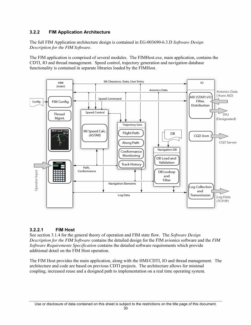
3.2.2 FIM Application Architecture
The full FIM Application architecture design is contained in EG-003690-6.3.D Software Design Description for the FIM Software.
The FIM application is comprised of several modules. The FIMHost.exe, main application, contains the CDTI, IO and thread management. Speed control, trajectory generation and navigation database functionality is contained in separate libraries loaded by the FIMHost.
3.2.2.1 FIM Host See section 3.1.4 for the general theory of operation and FIM state flow. The Software Design Description for the FIM Software contains the detailed design for the FIM avionics software and the FIM Software Requirements Specification contains the detailed software requirements which provide additional detail on the FIM Host operation.
The FIM Host provides the main application, along with the HMI/CDTI, IO and thread management. The architecture and code are based on previous CDTI projects. The architecture allows for minimal coupling, increased reuse and a designed path to implementation on a real time operating system.

Use or disclosure of data contained on this sheet is subject to the restrictions on the title page of this document. 31
Figure 18 FIM Host Executive Architecture
The FIM Host IO configures the AID via STAP configuration, as described in 3.1.3. The AID retrieves the requested bus data and passes it to the FIM Host over an Ethernet connection. Connection and interfacing with the AID are described in D06412904-B G700AB Software Design Guide and the ARINC 834 Aircraft Data Interface Function standard for the STAP protocol.
The FIM Host IO stores received data in a ping-pong buffer which is available to Speed Control and Trajectory Generator. Speed Control and Trajectory Generator in turn store results in the ping pong data buffer for use by the HMI and IO functions.
The HMI/CDTI provides the user interface and information display. The HMI follows the NASA implementation, adapted to a landscape orientation and soft buttons to better suit the EFB, CGD and provide the most usable display area. The HMI wireframe design is fully documented in the EG-003690-6.3.D Software Design Description for the FIM Software.
The Build Manager is responsible for implementing the FIM state machine, previously described in 3.1.4.1, and invoking the Speed Control and Trajectory Generator according to the state flow, which is driven by user actions and data inputs.

Use or disclosure of data contained on this sheet is subject to the restrictions on the title page of this document. 32
The FIM Host also provides several general services necessary for the system operation. The EFB Data Receiver manages input synchronization between the master and slave EFB. The MonEFB server provides data logging capabilities used by all of the FIM modules. Additionally config file handling, local data logging and error handling services are provided.
3.2.2.2 Speed Control
See section 3.1.6 for Speed Control theory of operation which describes the general operation and data flow for the Speed Control module. The Software Design Description for the FIM Software contains the detailed design for the FIM avionics software and the FIM Software Requirements Specification contains the detailed software requirements which provide additional detail on the Speed Control operation.
The following show the internal sequence diagrams, describing the internal architecture of the Speed Control module. Refer to the Speed Control source code package, section 6.0 provided for implementation details.
Figure 19 Speed Control Power Up Sequence Diagram
Figure 19 shows the control flow when the InitSpeedControl() interface is invoked first time by HMI after loading the speed control module. InitSpeedControl() creates a singleton instance of the Speed Control Interface and Error Handler. Speed Control Interface instantiates the Speed Control Handler and Speed Control Handler creates a Singleton instance of Speed Control Inputs.

Use or disclosure of data contained on this sheet is subject to the restrictions on the title page of this document. 33
Figure 20 Speed Control Setup Sequence
Figure 20 illustrates the control flow for setting up a new Spacing Clearance, and sets TG valid.
SpeedControl1HzHandler() is an export interface to the HMI and is invoked once every second. Control flows via the Go() function to Speed Control Interface’s periodic function which in turn invokes Speed Control Handler's periodic function.
SC Handler invokes the SpeedControlInputs::ProcessInputs() function which updates the inputs from HMI/IO for use by other Speed Control modules. It also updates the inputs from TG by getting the latest inputs for the current iteration using TG interface get_trajectory_interval_managment_record().
When the TG is ready with valid inputs, SC instantiates the appropriate Spacing Clearance object as defined by the clearance type.
o For MAINTAIN & CAPTURE, a CTD object is instantiated.
o For SPACE, TBO object is instantiated.

Use or disclosure of data contained on this sheet is subject to the restrictions on the title page of this document. 34
o For CROSS, both TBO and CTD are instantiated
Figure 21 Spacing Clearance Sequence Diagram
Figure 21 shows the control flow sequence when a valid Spacing Clearance is setup and TG inputs to Speed Control are valid. SC Handler invokes the periodic functions of the Spacing Clearance object instance.
Based on the setup clearance type and input condition ABP Passed/Not passed, the Spacing Clearance i periodic handler invokes the applicable control law periodic handler as follows.
o If clearance type is SPACE or CROSS (Before ABP), TBO’s periodic handler is invoked.
o If clearance type is MAINTAIN or CAPTURE or CROSS (After ABP), CTD’s periodic handler is invoked.
The TBO/CTD periodic handler computes Command IM Speed, Instantaneous Speed and outputs to HMI. If IM State is PAIRED, the handler periodic function also invokes the Speed Conformance

Use or disclosure of data contained on this sheet is subject to the restrictions on the title page of this document. 35
Monitor periodic function which monitors Aircraft CAS/Mach conformance to expected CAS/Mach values. The result is used to drive the HMI Speed conformance output (IM Command flashing). SpeedControl1HzHandler() sets the outputs into Speed Control Outputs before returning the control back to HMI where the results are consumed.
Figure 22 Spacing Clearance Cleanup Sequence Diagram
The Spacing Clearance Cleanup sequence is followed when the TG inputs to Speed Control become invalid. During this sequence the Spacing Clearance object is deleted, which in turn deletes the control law objects.

Use or disclosure of data contained on this sheet is subject to the restrictions on the title page of this document. 36
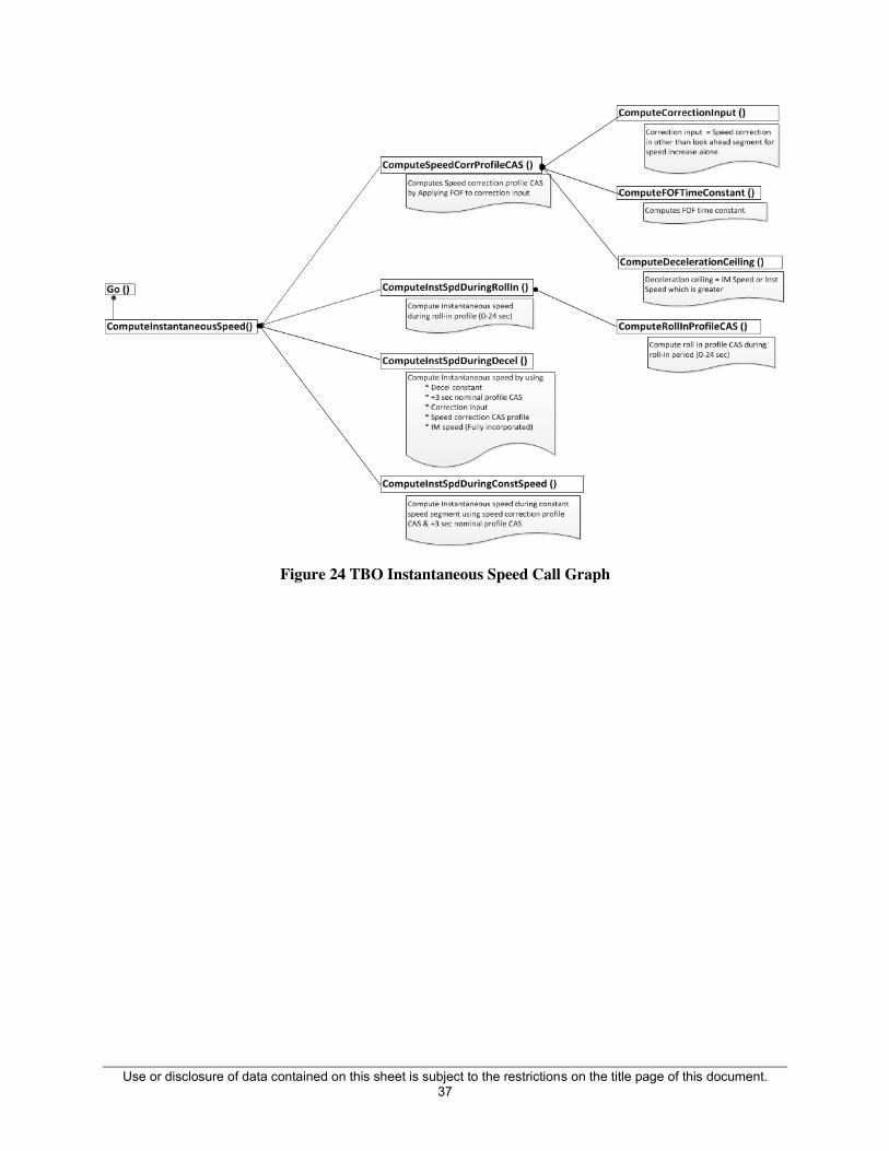
The following call graphs illustrate the arrangement and connectivity between the functions within the Speed Control module.
Figure 23 TBO Speed Correction & Commanded IM Speed Call Graph
Use or disclosure of data contained on this sheet is subject to the restrictions on the title page of this document. 37
Figure 24 TBO Instantaneous Speed Call Graph

Use or disclosure of data contained on this sheet is subject to the restrictions on the title page of this document. 38
Figure 25 CTD Call Graph

Use or disclosure of data contained on this sheet is subject to the restrictions on the title page of this document. 39
Figure 26 CTD Commanded IM Speed Call Graph
3.2.2.3 Trajectory Generator
See section 3.1.5 for Trajectory Generator theory of operation which describes the general operation of the TG module. The Software Design Description for the FIM Software contains the detailed design for the FIM avionics software and the FIM Software Requirements Specification contains the detailed software requirements which provide additional detail on the Trajectory Generator operation.
The following shows the internal architecture of the module.
Use or disclosure of data contained on this sheet is subject to the restrictions on the title page of this document. 40
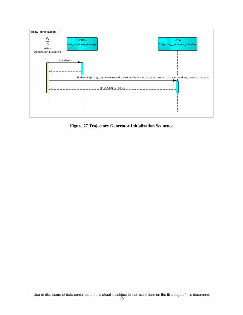
Figure 27 Trajectory Generator Initialization Sequence
sd TG - Initialization
«HMI»Application Executive
«DBM»Nav_database_manager
«TG»Trajectory_generator_initialize
initialize_trajectory_generator(nav_db_start_address, nav_db_size, custom_db_start_address, custom_db_size)
initialize()
:TRJ_GEN_STATUS

Use or disclosure of data contained on this sheet is subject to the restrictions on the title page of this document. 41
A. Lateral Revision Interface
Figure 28 Trajectory Generator Lateral Revision Sequence
sd TG - Lateral Rev ision Interface
«HMI»Application Executive
Trajectory_generator«DBM»DatabaseManager
alt
[if TOKEN is valid]
For insertion of any flight plan element into the TG, clients have to get the database keys of the element from Database manager. If key is valid, then invoke the flight planning interface of TG. This pattern holds true for every flight plan interface provided by TG
is_destination_airport_valid(airport ident)
:TOKEN
insert_destination_airport(PLAN_ID, DB_KEY):TRJ_GEN_STATUS

Use or disclosure of data contained on this sheet is subject to the restrictions on the title page of this document. 42
B. Periodic update Interface
Figure 29 Trajectory Generator Periodic Sequence
sd TG - Periodic Update
Application executive invokes TG periodically with current aircraft state parameters. TG determines if trajectory reconstruction is required. If the aircraft has deviated beyond a particular limit from original path, a reconstruction is performed.TG updates the progress data with the input aircraft state parameters. Following this TG clients can now query TG requesting updated progress data along interested points
«HMI»Application Executive
Trajectory_generator
alt Trajectory reconstruction required
trajectory_periodic_processing(PLAN_ID, Sensed_aircraft_state_parameters* const)
update_progress_data()
generate_trajectory(PLAN_ID, Sensed_aircraft_state_parameters* const): TRJ_GEN_STATUS
Use or disclosure of data contained on this sheet is subject to the restrictions on the title page of this document. 43
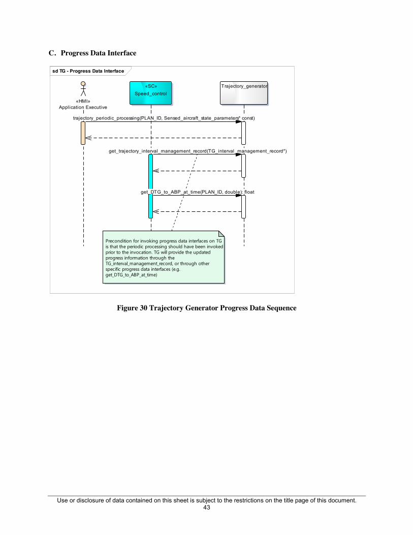
C. Progress Data Interface
Figure 30 Trajectory Generator Progress Data Sequence
3.3 Interfaces
sd TG - Progress Data Interface
«SC»Speed_control
Trajectory_generator
«HMI»Application Executive
Precondition for invoking progress data interfaces on TG is that the periodic processing should have been invoked prior to the invocation. TG will provide the updated progress information through the TG_interval_management_record, or through other specific progress data interfaces (e.g. get_DTG_to_ABP_at_time)
get_trajectory_interval_management_record(TG_interval_management_record*)
trajectory_periodic_processing(PLAN_ID, Sensed_aircraft_state_parameters* const)
get_DTG_to_ABP_at_time(PLAN_ID, double): float

Use or disclosure of data contained on this sheet is subject to the restrictions on the title page of this document. 44
Figure 31 Trajectory Generator Interface Data
class TG - Interface Data Types
vector
«typedef»Flight_plan_element_v ector
Flight_plan_element_vector::iterator
«typedef»Flight_plan_element_iterator
«struct»Sensed_aircraft_state_parameters
+ d_is_airborne_b: bool+ d_latitude: double+ d_longitude: double+ d_heading: double+ d_track: double+ d_time_in_seconds: double+ d_wind_direction: double+ d_altitude: float+ d_CAS: float+ d_TAS: float+ d_mach: float+ d_ground_speed: float+ d_temperature: float+ d_total_pressure: float+ d_wind_speed: float
«struct»Traffic_info
+ d_flight_id: char ([TG_FLIGHT_ID])+ d_track_id: char+ d_lattitude: double+ d_longitude: double+ d_altitude: float+ d_ground_speed: short+ d_track_angle: float+ d_raw_value: int
«struct»Traffic_record
+ d_time_frame: unsigned long+ d_traffic_record: Traffic_info ([TG_MAX_TRAFFIC_INFO])
__int64
«typedef»DB_KEY
«enumeration»PLAN_ID
OWNSHIP_e = 0 TARGET_e
«enumeration»Waypoint_type
DEFAULT_e = 0 MERGE_POINT_e ACHEIVE_BY_POINT_e PLANNED_TERMINATION_POINT_e
«enumeration»Speed_type
CAS_e = 0 MACH_e TAS_e GROUND_SPEED_e
«struct»IDENT
+ d_ident: char ([MAX_ID_LENGTH])
«struct»Wind_record
+ d_speed_knots: double+ d_wind_direction_degrees: double+ d_altitude_feet: double
«struct»Waypoint_wx_record
+ d_waypoint_db_key: DB_KEY+ d_wind_info: Wind_record+ d_instance_id: int
«struct»Temperature_record
+ d_altitude_feet: double+ d_temp_degree_celcius: double
«struct»Cruise_wind
+ d_speed_knots: double+ d_wind_direction_degrees: double
«struct»Position_record
+ d_latitude: double+ d_longitude: double+ d_validity_b: bool
«struct»Waypoint
+ d_ident: char ([MAX_ID_LENGTH])+ d_waypoint_position: Position_record+ d_waypoint_type: Waypoint_type
«struct»Trip_segment_record
+ d_dist_to_go: float+ d_enroute_time: double+ d_sequence_status_b: bool+ d_validity_b: bool
«struct»Aircraft_dynamic_state
+ d_speed: float+ d_position: Position_record+ d_active_waypoint: Waypoint+ d_speed_type: Speed_type
«struct»Segment_speed_record
+ d_current_segment_speed: float+ d_next_segment_speed: float+ d_enroute_time_current_segment_end_point: double+ d_current_segment_speed_type: Speed_type+ d_next_segment_speed_type: Speed_type«struct»
Lead_speed
+ d_three_sec_lead_speed: float+ d_nine_sec_lead_speed: float+ d_three_sec_lead_speed_validity_b: bool+ d_nine_sec_lead_speed_validity_b: bool
«enumeration»Spacing_goal_type
NONE_e TIME_e DISTANCE_e
«struct»Assigned_spacing_goal_record
+ d_TTG_to_ASG_distance: double+ d_DTG_to_ASG_time: float+ d_spacing_goal: Spacing_goal_type
«struct»TG_interv al_management_record
+ d_ownship_to_TTF: Trip_segment_record+ d_ownship_to_ABP: Trip_segment_record+ d_ownship_to_PTP: Trip_segment_record+ d_TTF_to_ABP: Trip_segment_record+ d_TTF_to_PTP: Trip_segment_record+ d_ASG_ownship_to_ABP: Trip_segment_record+ d_ownship_lead_speed: Lead_speed+ d_current_ownship_state: Aircraft_dynamic_state+ d_current_TTF_state: Aircraft_dynamic_state+ d_ownship_segment_speed_record: Segment_speed_record+ d_ASG_record: Assigned_spacing_goal_record+ d_TTF_Actual_arrival_time_at_ABP: double+ d_TTF_time_at_ownship_position: double+ d_DTG_ownship_to_ABP_at_ETA_of_TTF: float+ d_ownship_trajectory_info_valid: bool+ d_TTF_trajectory_info_valid: bool+ d_ownship_off_route: bool+ d_TTF_off_route: bool+ d_ownship_bad_route: bool+ d_TTF_bad_route: bool
«enumeration»TRJ_GEN_STATUS
TG_SUCCESS_e TG_FAILURE_e TG_INVALID_INPUT_e
+d_traffic_record
+d_active_waypoint
+d_waypoint_position
+d_waypoint_db_key
+d_next_segment_speed_type
+d_spacing_goal
+d_current_segment_speed_type
+d_current_TTF_state
+d_wind_info
+d_ownship_lead_speed
+d_speed_type
+d_position
+d_ownship_to_TTF+d_TTF_to_ABP
+d_ownship_segment_speed_record
+d_ownship_to_ABP
+d_current_ownship_state
+d_waypoint_type
+d_TTF_to_PTP+d_ASG_ownship_to_ABP+d_ownship_to_PTP+d_ASG_record

Use or disclosure of data contained on this sheet is subject to the restrictions on the title page of this document. 45
3.3.1.1 Navigation Database
See section 3.1.7 for Navigation Database theory of operation which describes the general operation of the Nav DB module. The Software Design Description for the FIM Software contains the detailed design for the FIM avionics software and the FIM Software Requirements Specification contains the detailed software requirements which provide additional detail on the Navigation Database operation. The following shows the internal architecture of the module.

Use or disclosure of data contained on this sheet is subject to the restrictions on the title page of this document. 46
Figure 32 Use Case Diagram For DBM Module Interaction
The ATD application executive initiates the NAVDB loading and custom DB loading. The initialization status will be provided back to the user to indicate the initialization was successful or unsuccessful. The executive also needs to set the appropriate Database cycle. Usually this should match with the onboard avionics Navigation database cycle.
sd DB Access Activ ity
:ATD Wrapper
ATD Application
:SSL_DBM.LIB
Query navdb(ident)
NavDB loaded status()
Custom DB loaded status()
load custom DB(file start address, size)
retrieve records()
Custom DB Initialization(fi le path)
Records()
Open Database(database start address, size)
:Token
NavDB Initialization(database path)
policy find(ident)
Get records(Token)

Use or disclosure of data contained on this sheet is subject to the restrictions on the title page of this document. 47
Figure 33 Use Case Diagram for DBM Loading
uc ATD_DBM Use cases
ATD_DBM
ATD Application
Nav DB Loading
Custom DB LoadingCustom DB Pool
Creation
DB Integrity Check
Nav DB Access Custom DB Access
Custom DB Update Set NDB Cycle
«include»
«extend»
«extend»
«include»
«include»

Use or disclosure of data contained on this sheet is subject to the restrictions on the title page of this document. 48
3.3.1.2 FIM Host Interface
The following table documents the inter-module data interface. With the exception of the Speed Control module, the detailed interface API is not provided. The Speed Control source code containing the API is provided as a separate source code package.
Sl No. Source Destination Parameter Units Data Type Comments
1 EFB-HMI Spd-Ctrl IM_State n/a enum
ARMED, AVAILABLE,SUSPEND,RESUME,PAIRED,CANCEL
2 EFB-HMI Spd-Ctrl ASG n/a Float eg: 120.0
3 EFB-HMI Spd-Ctrl ASG_Units Sec or NM enum eSEC, eNM
4 EFB-HMI Spd-Ctrl DesignatedTrafficID n/a char* eg: ASQ7Q44
5 EFB-HMI Spd-Ctrl IM_ClearanceType n/a enum MAINTAIN, CAPTURE,CROSS,SPACING,NONE
6 EFB-HMI Spd-Ctrl Altitude entry for Wind Feet int eg:10000, 0 for Surface
7 EFB-HMI TG Ownship_IFPI_Record n/a struct
Contains upto 10 IFPI elements entered by crew manually or by selection of arrival ,approach and transition
8 EFB-HMI TG DescentWinds n/a struct
Contains upto 5 altitudes including surface and corresponding wind direction and speed.
9 EFB-HMI TG ABP n/a struct
Contains an Ident of a waypoint common to Tgt and Ownship and an along path distance from this waypoint where Achieve By Point is desired.
10 EFB-HMI TG PTP n/a struct
Contains an Ident of a waypoint common to Tgt and Ownship and an along path distance from this waypoint where Planned Termination Point is desired.
11 EFB-HMI TG IM_ClearanceType n/a enum MAINTAIN, CAPTURE,CROSS,SPACING,NONE

Use or disclosure of data contained on this sheet is subject to the restrictions on the title page of this document. 49
Sl No. Source Destination Parameter Units Data Type Comments
12 EFB-HMI TG Dest ICAO char* eg: KDEN
13 EFB-HMI TG Ownship_IFPI_Record n/a struct
Contains upto 10 IFPI elements entered by crew manually or by selection of arrival ,approach and transition . Also wind speed and direction are included for each waypoint if entries were made.
14 EFB-HMI TG HMI.Tgt_IFPI_Record n/a struct
Contains upto 5 waypoints entered by crew manually or by selection of arrival ,approach and transition . Also wind speed and direction are included for each waypoint if entries were made.
15 EFB-HMI TG IM TARGET APPROACH n/a char* eg: ILS17R
16 EFB-HMI TG Selected RANGE NM float eg: 25.0
17 IO TG Traffic Data record n/a struct The Entire Traffic List as received from TCAS
18 EFB-HMI TG DescentWinds n/a struct
Contains upto 5 altitudes including surface and corresponding wind direction and speed.
19 EFB-HMI TG Ownship_IFPI_Record n/a struct
Contains upto 10 waypoints entered by crew manually or by selection of arrival ,approach and transition . Also wind speed and direction are included for each waypoint if entries were made.
20 EFB-HMI TG ABP n/a struct
Contains an Ident of a waypoint common to Tgt and Ownship and an along path distance from this waypoint where Achieve By Point is desired.
21 EFB-HMI TG PTP n/a struct
Contains an Ident of a waypoint common to Tgt and Ownship and an along path distance from this waypoint where Planned Termination Point is desired.

Use or disclosure of data contained on this sheet is subject to the restrictions on the title page of this document. 50
Sl No. Source Destination Parameter Units Data Type Comments
22 Spd-Ctrl EFB-HMI SpeedConformanceMonitor
In Conformance/ Out Of Conformance enum
23 Spd-Ctrl EFB-HMI SpacingInterval N/a int Spacing Interval
24 Spd-Ctrl EFB-HMI SpacingIntervalUnits NM/Secs enum Spacing interval units
25 Spd-Ctrl EFB-HMI ASG_Time n/a int Assigned Spacing Goal in secs
26 Spd-Ctrl EFB-HMI ASG_Dist Sec or NM enum Assigned Spacing Goal in NM
27 NavDB EFB-HMI IM CAUTION, ADVISORY and INFO MESSAGES n/a enum NM/Secs
28 NavDB EFB-HMI Airports ICAO Array of char* List of Airport Names
29 NavDB EFB-HMI Arrival n/a Array of char* List of Arrivals for the Airport
30 NavDB EFB-HMI Transision n/a Array of char* List of Transision for the Arrial
31 NavDB EFB-HMI Approach n/a Array of char*
List of Approach for the Arrival List of Approach for the Transition List of Approach for the Arrival and Transition
32 EFB-HMI Spd-Ctrl CASMachSelection n/a enum DEFAULT, MACH, CAS
33 IO Spd-Ctrl Ownship Maximum Operating Limit Speed - CAS (Vmo)
34 IO Spd-Ctrl Ownship Maximum Operating Limit Speed - Mach (Mmo) MACH float
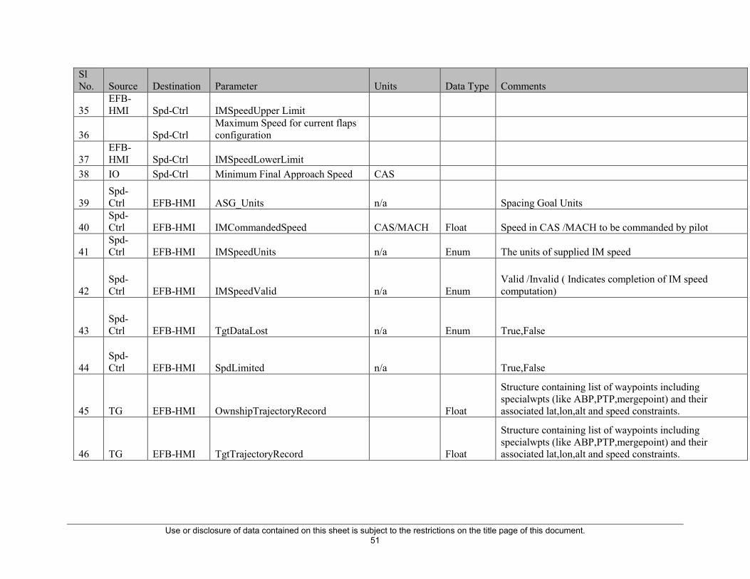
Use or disclosure of data contained on this sheet is subject to the restrictions on the title page of this document. 51
Sl No. Source Destination Parameter Units Data Type Comments
35 EFB-HMI Spd-Ctrl IMSpeedUpper Limit
36 Spd-Ctrl Maximum Speed for current flaps configuration
37 EFB-HMI Spd-Ctrl IMSpeedLowerLimit
38 IO Spd-Ctrl Minimum Final Approach Speed CAS
39 Spd-Ctrl EFB-HMI ASG_Units n/a Spacing Goal Units
40 Spd-Ctrl EFB-HMI IMCommandedSpeed CAS/MACH Float Speed in CAS /MACH to be commanded by pilot
41 Spd-Ctrl EFB-HMI IMSpeedUnits n/a Enum The units of supplied IM speed
42 Spd-Ctrl EFB-HMI IMSpeedValid n/a Enum
Valid /Invalid ( Indicates completion of IM speed computation)
43 Spd-Ctrl EFB-HMI TgtDataLost n/a Enum True,False
44 Spd-Ctrl EFB-HMI SpdLimited n/a True,False
45 TG EFB-HMI OwnshipTrajectoryRecord Float
Structure containing list of waypoints including specialwpts (like ABP,PTP,mergepoint) and their associated lat,lon,alt and speed constraints.
46 TG EFB-HMI TgtTrajectoryRecord Float
Structure containing list of waypoints including specialwpts (like ABP,PTP,mergepoint) and their associated lat,lon,alt and speed constraints.

Use or disclosure of data contained on this sheet is subject to the restrictions on the title page of this document. 52
Sl No. Source Destination Parameter Units Data Type Comments
47 TG EFB-HMI IM_ApplicationInfoValid Valid /Invalid Enum
If any IM Application Information (for all of “a” through “e” above) is Invalid, the FIM Avionics System shall (FRAC.014) set the IM Application Information Status to Invalid and provide the Invalid IM Application Information Criteria to the HMI/CDTI Interface.
48 TG EFB-HMI OwnshipOffRoute True,False Enum
4.1.3.3 Horizontal Path Conformance Monitoring Status MOPS Status: Modified The Ownship and Designated Traffic are expected to comply with the navigation requirements associated with the procedure(s) identified by the Intended Flight Path Information (IFPI). Horizontal Path Conformance Monitoring Status identifies when the Ownship or the Designated Traffic are not conforming to the Horizontal Path calculated by the FIM Avionics System, which may result in significant errors in the PSI or MSI and thus Commanded IM Speeds.
49 TG EFB-HMI TgtOffRoute True,False Enum
4.1.3.3 Horizontal Path Conformance Monitoring Status MOPS Status: Modified The Ownship and Designated Traffic are expected to comply with the navigation requirements associated with the procedure(s) identified by the Intended Flight Path Information (IFPI). Horizontal Path Conformance Monitoring Status identifies when the Ownship or the Designated Traffic are not conforming to the Horizontal Path calculated by the FIM Avionics System, which may result in significant errors in the PSI or MSI and thus Commanded IM Speeds.

Use or disclosure of data contained on this sheet is subject to the restrictions on the title page of this document. 53
Sl No. Source Destination Parameter Units Data Type Comments
50 TG EFB-HMI OwnshipTTGABP Seconds Integer
4.1.3.2.14 Time-to-Go Calculation MOPS Status: Modified (Not everything included from sections C.3.3-4 in Appendix C of MOPS for FIM V7.0) For the Achieve Stage, the FIM Avionics System shall be capable of calculating the Ownship’s Time-to-Go to the Achieve-by Point from the current Along-path Position that is consistent with the Ground Speed Profile
51 TG EFB-HMI OwnshipDTGABP NM Integer
4.1.3.2.14 Time-to-Go Calculation MOPS Status: Modified (Not everything included from sections C.3.3-4 in Appendix C of MOPS for FIM V7.0) For the Achieve Stage, the FIM Avionics System shall be capable of calculating the Ownship’s Time-to-Go to the Achieve-by Point from the current Along-path Position that is consistent with the Ground Speed Profile
52 TG EFB-HMI PTPMonitoringStatus Reached/Not Reached Enum
4.1.10 Planned Termination Point Monitoring Status MOPS Status: As Is FIM Avionics System will monitor the Along-path Position of the Ownship and indicate to CDTI when Ownship has reached Planned Termination Point. The Planned Termination Point Monitoring Status is in one of the following two states: 1. “Not Reached:” Ownship’s Along-path Position has not reached the Planned Termination Point. 2. “Reached:” Ownship’s Along-path Position has reached the Planned Termination Point
53 TG EFB-HMI PTPWpt
Planned termination point
Waypoint Record

Use or disclosure of data contained on this sheet is subject to the restrictions on the title page of this document. 54
Sl No. Source Destination Parameter Units Data Type Comments
54 TG EFB-HMI TgtBadRoute True,False Enum
A valid Ownship traffic record and an Ownship route definition exists, but the calculated trajectory cannot be calculated, or it does not meet speed or altitude constraints
55 TG EFB-HMI OwnshipBadRoute True,False Enum
A valid Target traffic record and a Target route definition exists, but the calculated trajectory cannot be calculated, or it does not meet speed or altitude constraints.
56 EFB-HMI TG IMInfoClear True,False enum Transient 2 secs signal to clear all IM information
57 IO EFB-HMI TCVertRAStatus Enum Enum For TCAS annunciation Display 58 IO EFB-HMI TCMode Enum Enum For TCAS annunciation Display 59 IO EFB-HMI TCModeStatus Enum Enum For TCAS annunciation Display 60 IO EFB-HMI TrfcAppAvailableStatus Enum enum Traffic Application availability word status 61 IO EFB-HMI TrfcEVAcqGrpAvail Enum enum EV Acq application availability 62 IO EFB-HMI TrfcIntervalMgmtGrpAvail Enum enum IM application availbility 63 IO EFB-HMI TrfcGrndBasedGrpAvail Enum enum SURF appln availaibility 64 IO EFB-HMI TrfcEVApprGrpAvail Enum enum EV appr Appln availbility 65 IO EFB-HMI TrfcItpGrpAvailable Enum enum ITP application availability 66 IO EFB-HMI TrfcFaultLabelStatus Enum enum For TCAS annunciation Display 67 IO EFB-HMI TrfcSystemStatus Enum enum For IM system status display 68 IO EFB-HMI AsasSystemStatus Enum enum For IM system status display 69 IO EFB-HMI TrfcDtifTransmit Enum Enum TCAS Dtif status 70 IO EFB-HMI TrfcDtifTransmitStatus Enum Enum TCAS Dtif status 71 IO EFB-HMI UTCTime Struct Float UTC time as reported by TCAS computer 72 IO EFB-HMI OwnshipTrackAngle float float Ownship track angle 73 IO EFB-HMI OwnshipTrackAngleStatus Enum enum Ownship track angle status 74 IO EFB-HMI OwnshipPressureAlt float float Ownship pressure altitude

Use or disclosure of data contained on this sheet is subject to the restrictions on the title page of this document. 55
Sl No. Source Destination Parameter Units Data Type Comments 75 IO EFB-HMI OwnshipPressureAltStatus Enum enum Ownship pressure altitude status 76 IO EFB-HMI OwnshipLatitudeCoarse float float 77 IO EFB-HMI OwnshipLatitudeCoarseStatus Enum enum 78 IO EFB-HMI OwnshipLongitudeCoarse float float 79 IO EFB-HMI OwnshipLongitudeCoarseStatus Enum enum 80 IO EFB-HMI OwnshipLongitudeFine float float 81 IO EFB-HMI OwnshipLongitudeFineStatus Enum enum 82 IO EFB-HMI OwnshipLatitudeFine float float 83 IO EFB-HMI OwnshipLatitudeFineStatus Enum enum 84 IO EFB-HMI OwnshipGroundSpeed float float 85 IO EFB-HMI OwnshipGroundSpeedStatus Enum enum 86 IO EFB-HMI OwnshipWindSpeed float float 87 IO EFB-HMI OwnshipWindSpeedStatus Enum enum 88 IO EFB-HMI OwnshipWindDirection float float 89 IO EFB-HMI OwnshipWindDirectionStatus Enum enum 90 IO EFB-HMI OwnshipMach float float 91 IO EFB-HMI OwnshipMachStatus Enum enum 92 IO EFB-HMI OwnshipCAS float float 93 IO EFB-HMI OwnshipCASStatus Enum enum 94 IO EFB-HMI OwnshipStaticAirTemp float float 95 IO EFB-HMI OwnshipStaticAirTempStatus Enum enum
96 IO Spd-Ctrl MaxIMSpeedCorrectionPercent percent int
The limits on the IM Speeds in the FIM Avionics System shall (new_2.2.4.5.3B) be configurable at installation with a default value of 15%.

Use or disclosure of data contained on this sheet is subject to the restrictions on the title page of this document. 56
Sl No. Source Destination Parameter Units Data Type Comments
97 IO Spd-Ctrl GroundSpeedToleranceWithTgtAC knots int
For Distance‐based ASG, after the Designated Traffic reaches the Planned Termination Point, and until Ownship reaches the Planned Termination Point, the FIM Avionics System shall (new_2.2.4.5A) compute IM Speeds such that the Ownship has a ground speed at the Planned Termination Point that is within 10 knots of the ground speed of the Designated Traffic at the Planned Termination Point.
98 IO Spd-Ctrl OwnshipCAS float float
When the IM Speed Mach/CAS selection is computed in CAS, the FIM Avionics System shall (FRAC.251) evaluate the Speed Conformance Monitoring Status on one (1) second intervals starting 11 seconds after the new IM Speed, and ending when Ownship’s CAS is within 5 knots of the new IM Speed.
99 IO Spd-Ctrl OwnshipCASStatus Enum enum 100 IO Spd-Ctrl OwnshipMach float float 101 IO Spd-Ctrl OwnshipMachStatus Enum enum
102 IO THDB Traffic Data record record struct All traffic data received from TPU 103 IO Spd-Ctrl OwnshipPressureAlt Feet float 104 IO Spd-Ctrl OwnshipPressureAltStatus enum Enum 105 IO Spd-Ctrl OwnshipWindSpeed knots float 106 IO Spd-Ctrl OwnshipWindSpeedStatus Enum Enum 107 IO Spd-Ctrl OwnshipWindDirection deg float 108 IO Spd-Ctrl OwnshipWindDirectionStatus Enum Enum 109 IO Spd-Ctrl OwnshipStaticAirTemp float 110 IO Spd-Ctrl OwnshipStaticAirTempStatus Enum Enum
111 TG Spd-Ctrl OwnshipABPMonitor Passed/Not Passed enum Ownship Passed ABP
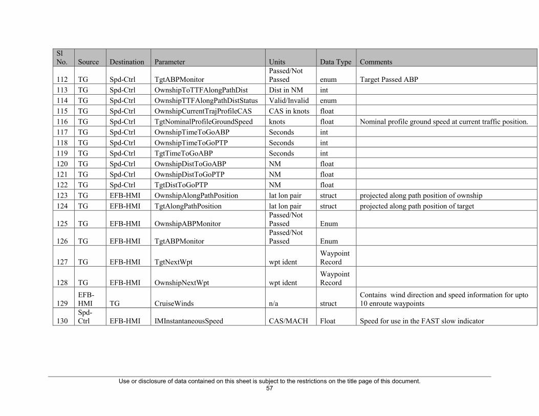
Use or disclosure of data contained on this sheet is subject to the restrictions on the title page of this document. 57
Sl No. Source Destination Parameter Units Data Type Comments
112 TG Spd-Ctrl TgtABPMonitor Passed/Not Passed enum Target Passed ABP
113 TG Spd-Ctrl OwnshipToTTFAlongPathDist Dist in NM int 114 TG Spd-Ctrl OwnshipTTFAlongPathDistStatus Valid/Invalid enum 115 TG Spd-Ctrl OwnshipCurrentTrajProfileCAS CAS in knots float 116 TG Spd-Ctrl TgtNominalProfileGroundSpeed knots float Nominal profile ground speed at current traffic position. 117 TG Spd-Ctrl OwnshipTimeToGoABP Seconds int 118 TG Spd-Ctrl OwnshipTimeToGoPTP Seconds int 119 TG Spd-Ctrl TgtTimeToGoABP Seconds int 120 TG Spd-Ctrl OwnshipDistToGoABP NM float 121 TG Spd-Ctrl OwnshipDistToGoPTP NM float 122 TG Spd-Ctrl TgtDistToGoPTP NM float 123 TG EFB-HMI OwnshipAlongPathPosition lat lon pair struct projected along path position of ownship 124 TG EFB-HMI TgtAlongPathPosition lat lon pair struct projected along path position of target
125 TG EFB-HMI OwnshipABPMonitor Passed/Not Passed Enum
126 TG EFB-HMI TgtABPMonitor Passed/Not Passed Enum
127 TG EFB-HMI TgtNextWpt wpt ident Waypoint Record
128 TG EFB-HMI OwnshipNextWpt wpt ident Waypoint Record
129 EFB-HMI TG CruiseWinds n/a struct
Contains wind direction and speed information for upto 10 enroute waypoints
130 Spd-Ctrl EFB-HMI IMInstantaneousSpeed CAS/MACH Float Speed for use in the FAST slow indicator

Use or disclosure of data contained on this sheet is subject to the restrictions on the title page of this document. 58
Sl No. Source Destination Parameter Units Data Type Comments
131 TG Spd-Ctrl OwnshipPTPMonitoringStatus Reached/Not Reached Enum
4.1.10 Planned Termination Point Monitoring Status MOPS Status: As Is FIM Avionics System will monitor the Along-path Position of the Ownship and indicate to CDTI when Ownship has reached Planned Termination Point. The Planned Termination Point Monitoring Status is in one of the following two states: 1. “Not Reached:” Ownship’s Along-path Position has not reached the Planned Termination Point. 2. “Reached:” Ownship’s Along-path Position has reached the Planned Termination Point
132 TG Spd-Ctrl OwnshipTTGtoTTFPosition Seconds int Ownship Time to go to TTF current position. 133 TG Spd-Ctrl OwnshipCurrentSegmentEndSpeed knots Float 134 TG Spd-Ctrl OwnshipNextSegmentEndSpeed knots Float
135 TG Spd-Ctrl OwnshipTTGtoEndOfCurrent SpeedSegment
136 TG Spd-Ctrl OwnshipTTGtoPointASGDistanceFromABP Seconds int Time Equivalent of Distance based spacing.
137 IO Spd-Ctrl CasMachCrossOverAltitude Feet Float 138 IO Spd-Ctrl OwnshipLatitudeCoarse float float 139 IO Spd-Ctrl OwnshipLatitudeCoarseStatus Enum enum 140 IO Spd-Ctrl OwnshipLongitudeCoarse float float 141 IO Spd-Ctrl OwnshipLongitudeCoarseStatus Enum enum 142 IO Spd-Ctrl OwnshipLongitudeFine float float 143 IO Spd-Ctrl OwnshipLongitudeFineStatus Enum enum 144 IO Spd-Ctrl OwnshipLatitudeFine float float 145 IO Spd-Ctrl OwnshipLatitudeFineStatus Enum enum 146 IO TG OwnshipLatitudeCoarse float float 147 IO TG OwnshipLatitudeCoarseStatus Enum enum

Use or disclosure of data contained on this sheet is subject to the restrictions on the title page of this document. 59
Sl No. Source Destination Parameter Units Data Type Comments 148 IO TG OwnshipLongitudeCoarse float float 149 IO TG OwnshipLongitudeCoarseStatus Enum enum 150 IO TG OwnshipLongitudeFine float float 151 IO TG OwnshipLongitudeFineStatus Enum enum 152 IO TG OwnshipLatitudeFine float float 153 IO TG OwnshipLatitudeFineStatus Enum enum 154 TG Spd-Ctrl TgtActualTimeOfArrivalatABP UTC time 155 THDB TG Designated Traffic History Buffer Struct
157 EFB-HMI THDB Designated Traffic ID Char array
158 IO Spd-Ctrl EpochTime Seconds int
159 TG Spd-Ctrl DesignatedTrafficsTimeAtCurrentOwnshipPosition Struct
160 TG Spd-Ctrl OwnshipDTGtoABPat<current time + TgtTimeToGoABP> NM
For distance based clearance in Achieve phase, the Predicted spacing interval is computed as the ownships distance to go at the time the deignated traffic is predicted to cross the ABP.
161 TG Spd-Ctrl OwnshipTrajProfileCASWith3secLead knots Float Ownship Profile Speed 3 seconds from now
162 TG Spd-Ctrl OwnshipTrajProfileCASat9secAfterSpeedSegmentStart knots Float Ownship profile Speed 9 seconds from start of a segment
163 Spd-Ctrl EFB-HMI SpacingErrorInTime Seconds int Spacing Error for the early late indicator
164 TG Spd-Ctrl TgtPTPMonitor Passed/Not Passed enum Target Passed PTP
165 TG Spd-Ctrl TgtTimeToGoPTP Seconds int Target Time to go PTP. 166 TG Spd-Ctrl TgtActualTOAatPTP Seconds int Target Actual Time of Arrival at PTP
167 TG Spd-Ctrl TgtTimeAtOwnshipProximatePosWith15secLead seconds int
Target history time at ownship proximate position +15 sec lead
168 TG Spd-Ctrl TgtReportedGroundSpeed knots float Reported ground speed at current traffic position.

Use or disclosure of data contained on this sheet is subject to the restrictions on the title page of this document. 60
Sl No. Source Destination Parameter Units Data Type Comments
169 TG Spd-Ctrl TgtNominalHistoryCAS knots Float
Traffic's time history data from 15 seconds in front of the ownship's current position converted to CAS using avergae ground speed.
170 IO Spd-Ctrl OwnshipPressureAlt float float Ownship pressure altitude 171 IO Spd-Ctrl OwnshipPressureAltStatus Enum enum Ownship pressure altitude status

Use or disclosure of data contained on this sheet is subject to the restrictions on the title page of this document. 61
3.3.2 Data Logging
Data logging is performed by a combination of the EFB FIM software, the TPU software and external data logging applications. The data logging elements are highlighted in the diagram below.
Figure 34 Aircraft Data Logging Environment

Use or disclosure of data contained on this sheet is subject to the restrictions on the title page of this document. 62
The red lines in the diagram above indicate the logging data flow from the EFB and TPU. The TPU and FIM software use the same data logging methodology. Both transmit log data via Ethernet to a data logging PC. TPU data is logged by the legacy MonTPA application while EFB data is logged by the MonEFB software. MonEFB is derived from MonTPA, with modifications to display EFB data rather than TPU data. Two instances of MonEFB may run on the data logging PC to capture data from both EFBs.
Both MonEFB and MonTPA are capable of displaying live data as it is received, and capture data to a binary log file. Post exercise, the binary log files can be parsed out into CSV files using the existing xcribe parsing software for further analysis.
The data logging applications MonTPA and MonEFB run on a single data logging PC, external to the FIM avionics.
The same data logging system is available in integration lab and the aircraft.
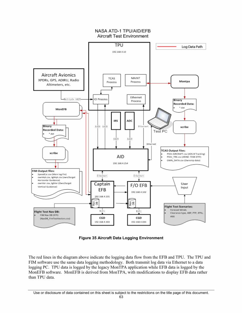
Use or disclosure of data contained on this sheet is subject to the restrictions on the title page of this document. 63
Figure 35 Aircraft Data Logging Environment
The red lines in the diagram above indicate the logging data flow from the EFB and TPU. The TPU and FIM software use the same data logging methodology. Both transmit log data via Ethernet to a data logging PC. TPU data is logged by the legacy MonTPA application while EFB data is logged by the MonEFB software. MonEFB is derived from MonTPA, with modifications to display EFB data rather than TPU data.

Use or disclosure of data contained on this sheet is subject to the restrictions on the title page of this document. 64
Both MonEFB and MonTPA are capable of displaying live data as it is received, and capture data to a binary log file. Post capture, the binary log files can be parsed out into CSV files using the Honeywell xcribe parsing software for further analysis. Xcribe uses parsing definition files (.def) which define not only how to read the binary data, but how to format the resulting CSV files – which fields to include, order, etc. The operation of the XCRIBE and definition files is described in the Honeywell XCRIBE Programming Manual.
The data logging applications MonTPA and MonEFB run on a data logging PC, external to the FIM avionics.
3.4 Interface Control Specifications
3.4.1 TPU to FIM Avionics ICD
The TPU bus interface is described in the TPA 100B Maintenance Manual. The FIM avionics application selects which data to receive, via the AID, using the STAP protocol. The AID latches the selected TPU data from the aircraft bus and transfers it to the FIM avionics application. The TPU data transferred to the FIM application is documented in Table 3 STAP Label Configuration.
3.4.2 TPU Dependency
The TPU used in the ATD-1 demonstration was a Honeywell TPA-100B with limited modifications to provide enhanced data for the FIM Host application. The FIM avionics as demonstrated is dependent on such a TPU.
The following modifications have been made to the Honeywell traffic computer to support the FIM software.
TCAS process:
x The IM Application now has its own set of crosschecks because of the different crosscheck requirements imposed by the NASA Spec.
x Logical changes made to always keep the Traffic to Follow (TTF) in the ESTB list, even if it is out prioritized by other traffic. If a given target matches the TTF, the target will always be promoted, demoting the traffic with the least priority on the list. If the TTF has the least priority on the list, and a new higher priority target is about to be promoted, a target with the second least priority will be demoted instead.
x Similar to the Mode S ID hash table, a Flight ID Hash Table has been created to keep track of duplicate flight ID’s.
Use or disclosure of data contained on this sheet is subject to the restrictions on the title page of this document. 65
I/O process:
x Logical changes made to reorder the DTIF to include the TTF when merging the active and passive lists together. If the TTF is specified, the DTIF’s ordering will be as follows:
o RA
o TA
o PA
o TTF
o all others with priority sorting
x Functional changes have been made to receive a DTIF (L366, L367) from the previously unused Traffic Display Control Bus #1/#2. The bus now processes a DTIF and pulls out the necessary information it needs from the intruder. In our case it is flight ID, but could later be modified to pull out other elements.
x The I/O Process now packs L165, L166, L174, L313, L110, L111, L120, and L121 according to ARINC 735B.
I/O output (hw output interface):
x The I/O Process now outputs Label 163, the application availability word, with the availability of the Interval Management availability in bits 14, 15 and 16.
x The I/O Process now outputs Label 366 Type 4, intruder information quality, with the Interval Management Quality Level in bits 17, and 18.
x The I/O Process now outputs an intruder’s velocity coast status in bit 14 of Label 366 Type 3.
x The I/O Process now outputs the following labels on the TA/RA Bus #1/#2 according to ARINC 735B

Use or disclosure of data contained on this sheet is subject to the restrictions on the title page of this document. 66
3.4.2.1 FIM Avionics Operator Troubleshooting Guide
3.4.2.1.1 FIM Host Software and Platform Troubleshooting Many of the potential FIM Host troubleshooting issues can be resolved by verifying the configuration file settings. The following are a list of checks to review when the FIM Host is not operating as expected.
x Ensure that the IP addresses for the master and slave do not conflict, and correct in the FIM Host configuration file. See the config file section.
x Verify the the EFB operates as expected without the FIM Host running – normal MS Windows functionality.
x Verify that the files in the FIM\ directory are from the intended version of the application and libraries from different versions are not loaded.
The FIM EFB platform is a COTS MS Windows based device. In the case of general platform errors the device should be powered down and restarted. Non-FIM Host crashes, operating error or hardware failures should be referred to the COTS vendor, United Technologies.
3.4.2.1.2 Aircraft Specific Troubleshooting
The FIM EFB and aircraft interface device (AID) are COTS products from United Technologies. The interface installation varies by aircraft. Document EG---3690-6.22 provides the installation plan as applied on the ATD-1 program.
Installation and troubleshooting of these devices should follow the UT installation guide appropriate for the specific aircraft. Section 2.3 includes references to vendor documents relevant to the ATD-1 equipment.
3.4.2.1.2.1 Installation Checkout The following steps can be used to verify the installation and identify possible installation errors. The following equipment is required:
x Two EFB
x One Aid
x Two CGD

Use or disclosure of data contained on this sheet is subject to the restrictions on the title page of this document. 67
x USB Power Hub (one is already on the aircraft)
x One Wireless Router (one is already on the aircraft)
x One TPA-100 Traffic Computer
x One TRA-100B
x Engineering Laptop with MonEFB, MonTPA and FIM Host software (for test director display)
3.4.2.1.2.2 Non-FIM Avionics
x The TRA-100B may or may not be certified by the time of the flight test, if it is not certified it will be considered part of the experimental equipment. Check out of the TPA-100B and TRA-100B should be done per the maintenance or installation manual appropriate for the equipment.
x All other required avionics should installed and maintained per normal aircraft procedures.
3.4.2.1.2.3 FIM Equipment Installation This test can be performed with partial equipment if necessary, but must be repeated for each EFB SDU and CGD location. For final checkout before flight test, all equipment must be installed. This description applies to the 757 configuration, other aircraft may be slightly different. Install and check out the items listed in the table below.
x Detailed instructions are provided after the table.
x Install and check: OK?
x TRA-100 Traffic Computer
x TRA-100B Transponder
x Wi-Fi Router
x USB Power Hub
x Aircraft Interface Device
x EFB Location 1 (Captain’s Side)
x EFB Location 2 (First Officer’s Side)

Use or disclosure of data contained on this sheet is subject to the restrictions on the title page of this document. 68
x CGD Location 1 (Captain’s Side)
x CGD Location 2 (First Officer’s Side)
x Engineering Laptop
x MonTPA
x MonEFB
x Test Director Display
If you need to verify or perform original installation, perform the following steps. If the installation has already been performed and the equipment configured, these steps are not necessary. (Initial install only) To make it easier to operate the EFB during the installation process, bring a USB hub, keyboard, mouse and memory stick. Configure files and manually start the system as follows:
1. Start the EFB (username: SDU password: SDU) and configure the Windows orientation appropriate for the side of the aircraft it is installed on. 2. Load the flight STAP config file if necessary. (alternate methods are available, one method is to connect a laptop computer to the Ethernet network, attached to the EFB using Windows file explorer (address \\192.168.4.101 for captain, \\192.168.4.101 for first officer. Copy the file StapLabelChannel_aircraft.conf to “StapLabelChannel.conf.” (These files are found in the Honeywell folder, build subfolder, config files folder). Repeat for Capt & FO EFBs. (This step may not be necessary if EFB’s have already been configured for flight) 3. If necessary, update cgd.htm in the directory below, edit with notepad: ws = new WebSocket("ws://192.168.4.102:9099 (May not be necessary if EFB’s have already been configured for flight) use 101 for captain’s side, 102 for first officer side. 4. Start the CGD Server (go to C:\honeywell\nodejs-v0.12.7\newcgd\...(pick latest folder)..\CGD.bat) 5. Start the FIM Host (go to C:\Honeywel\...(latest directory)…\FIMHost.exe start FimHost.exe) or use the desktop shortcut. 6. Connect the CGDs to the wireless network. This may need to be done manually using phone settings. (CGD may report no SIM card, this is normal) If manual connection is required, use SSID: TP-LINK_D89F26 Password: 27D889F26 Case Sensitive.) iPhone password, if there is one, is 123456)

Use or disclosure of data contained on this sheet is subject to the restrictions on the title page of this document. 69
3.4.2.1.2.4 Normal Start up This procedure applies after files have been configured per the previous section. If the EFB’s come up with a logon screen, enter:
User: SDU Password: SDU
Start the FIM application and CGDs: 1. On Capt, EFB double click “Primary” shortcut (this starts the FIM host application and the CGD server. By default, the Capt EFB will always be the master.) 2. On FO EFB double click “Secondary” shortcut (this starts the FIM host application but not the CGD server. By default the FO EFB will always be the slave.) 3. On Capt CGD, select the “Primary” shortcut (this will connect the CGD to the Primary/Master EFB). 4. On FO CGD, select the “Primary” shortcut (this will connect the CGD to the Primary/Master EFB, both Capt and FO CGD’s should always be connected to the Master). (Note that the CGD’s have a “Secondary” shortcut that should only be used if the Capt EFB is not operational and the FO EFB is acting as the master.) Since several required FIM inputs are not valid when the aircraft is not airborne (e.g. True Track, CAS, etc.) the system will always show IM SYS FAIL when stationary on the ground. To verify the correct inputs are being supplied, perform the Alternate Check below using the MonEFB tool. Alternative check:
1. Configure the MonEFB laptop to be on the 192.168.4.x subnetwork (use some address between 105..119, the WiFi route will be assigning address above this rage). 2. Verify the WiFi router is configured on this subnet (we use 192.168.4.117 for the router address) 3. Configure the WiFi router for DHCP (so iphones will get the address) 4. Connect Laptop with MonEFB 5. In the MonEFB Connection dialog, use the address 192.168.4.101 to connect to the captain EFB or 192.168.4.102 to connect to the FO EFB. 6. Verify the labels under IM Sys Fail Status in IM STATE page of MonEFB:
x GPS will be stale
x IM Availability will be UNAVAILBLE

Use or disclosure of data contained on this sheet is subject to the restrictions on the title page of this document. 70
Everything else should be FRESH or NORMAL or YES If the above produres to not produce the intended results, verify the IP addresses in the FIM Host configuration files, verify the AID installation and wiring per the manufacturers installation documentation appropriate for the specific aircraft.
3.4.2.1.2.5 Ground Functional Checks Since Flight Deck Interval Management is a strictly airborne procedure, only limited functional checks are possible in a ground test. The procedures above test basic connectivity. These additional tests check the few additional functions that can be tested on the ground.
x Run the TCAS self test, verify same pattern is shown on the TCAS and FIM CDTI
x Check the functions on the FIM application, captain side:
o Display Range setting
o Filter Selection
o Arc/Plan mode
x Reat above on the FO side
If the FIM software does not display correctly restart the EFB. If the functions continues to fail, resinstall the FIM software.

Use or disclosure of data contained on this sheet is subject to the restrictions on the title page of this document. 71
4.0 SAMPLE FILES
The following are sample configuration and data files for reference. These examples provide reasonable starting values as a reference or regression comparison.
4.1 Sample FIM Host Configuration Files
Below are sample FIM Host configuration files, as described in section 3.1.3.
4.1.1 ConfigIM.conf Sample ################################################################################################################################# ## Module name: IM Config Data ## ## Purpose: This Configuration file defines the IM configuration parameters and values ## ## Modification History: ## CR Date Name Comment ## --- ---- ---- ------- ## ## XX_XX 21-Mar-2016 PS Initial Revision. ## ## ## The format is <IMPARAM><EQUAL><IMPARAMVALUE> ## Comments start with '#' Symbol ################################################################################################################################# #################################### # IM Config Data # # <IMPARAM><EQUAL><IMPARAMVALUE> # #################################### AIR_SPEED_PROFILE_TOLERANCE_PERCENT = 1 TIME_BASED_TOLERANCE = 2 GROUND_SPEED_DIFFERENCE_AT_PTP = 3 MAX_IMSPEED_CHANGE_PERCENT = 15 ASG_MSI_DIFF = 5 VMO = 350 MMO = 0.8 IMSPEED_UPPER_LIMIT_IN_MACH = 0.77 IMSPEED_UPPER_LIMIT_IN_CAS = 540 IMSPEED_LOWER_LIMIT_IN_CAS = 120 MIN_FINAL_APPROACH_SPEED = 120 HORIZONTAL_PATH_CONFROMANCE_LIMIT = 9 CRUISE_PROFILE_ALTITUDE_IN_FL = 230 CRUISE_PROFILE_SPEED_IN_MACH = 0.75 DESCENT_PROFILE_SPEED_IN_CAS = 240 AIRSPACE_RESTRICTION_SPEED_IN_CAS = 250

Use or disclosure of data contained on this sheet is subject to the restrictions on the title page of this document. 72
AIRSPACE_RESTRICTION_ALTITUDE = 10000
4.1.2 EFBCom.conf ## ## Purpose: This EFB communication interfaces ## ## Modification History: ## CR Date Name Comment ## --- ---- ---- ------- ## ## XX_XX 09-DEC-2015 AR Initial Revision. ## XX_XX 25-AUG-2016 PS Test Director IP Added. ## ## ## The format is <LABEL><SPACE><IP ADDRESS> ## Comments start with '#' Symbol ################################################################################################################################# #################################### # EFB MASTER AND SLAVE # # <LABEL><SPACE><IP ADDRESS> # #################################### CAPTAINEFBIP 159.99.196.91 # Master side EFB IP FIRSTOFFICEREFBIP 159.99.196.129 # Slave side EFB IP TESTDIRECTOREFBIP 159.99.196.190 # Test Director EFB IP AIDUIP 192.168.4.254 # AIDU IP Address
4.1.3 StapLabelChannel.conf ################################################################################################################################# ## ## Module name: Label and Channel Configuration ## ## Purpose: This Configuration file defines the ARINC LABELS and their CHANNELS ## ## Modification History: ## CR Date Name Comment ## --- ---- ---- ------- ##
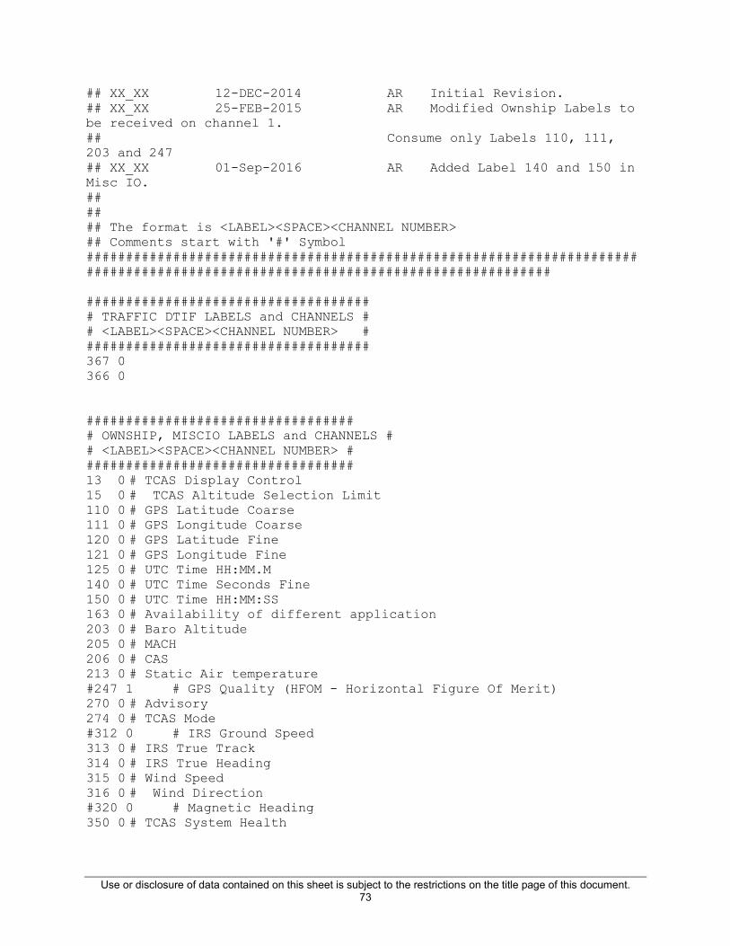
Use or disclosure of data contained on this sheet is subject to the restrictions on the title page of this document. 73
## XX_XX 12-DEC-2014 AR Initial Revision. ## XX_XX 25-FEB-2015 AR Modified Ownship Labels to be received on channel 1. ## Consume only Labels 110, 111, 203 and 247 ## XX_XX 01-Sep-2016 AR Added Label 140 and 150 in Misc IO. ## ## ## The format is <LABEL><SPACE><CHANNEL NUMBER> ## Comments start with '#' Symbol ################################################################################################################################# #################################### # TRAFFIC DTIF LABELS and CHANNELS # # <LABEL><SPACE><CHANNEL NUMBER> # #################################### 367 0 366 0 ################################## # OWNSHIP, MISCIO LABELS and CHANNELS # # <LABEL><SPACE><CHANNEL NUMBER> # ################################## 13 0 # TCAS Display Control 15 0 # TCAS Altitude Selection Limit 110 0 # GPS Latitude Coarse 111 0 # GPS Longitude Coarse 120 0 # GPS Latitude Fine 121 0 # GPS Longitude Fine 125 0 # UTC Time HH:MM.M 140 0 # UTC Time Seconds Fine 150 0 # UTC Time HH:MM:SS 163 0 # Availability of different application 203 0 # Baro Altitude 205 0 # MACH 206 0 # CAS 213 0 # Static Air temperature #247 1 # GPS Quality (HFOM - Horizontal Figure Of Merit) 270 0 # Advisory 274 0 # TCAS Mode #312 0 # IRS Ground Speed 313 0 # IRS True Track 314 0 # IRS True Heading 315 0 # Wind Speed 316 0 # Wind Direction #320 0 # Magnetic Heading 350 0 # TCAS System Health
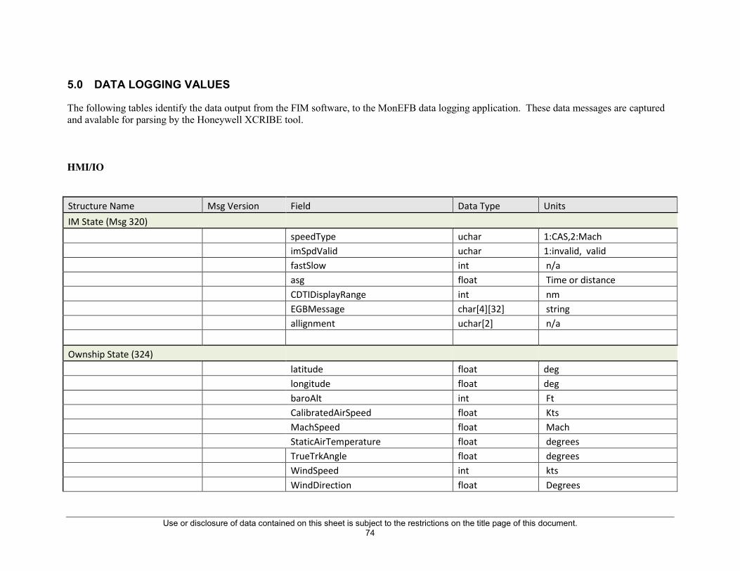
Use or disclosure of data contained on this sheet is subject to the restrictions on the title page of this document. 74
5.0 DATA LOGGING VALUES
The following tables identify the data output from the FIM software, to the MonEFB data logging application. These data messages are captured and avalable for parsing by the Honeywell XCRIBE tool. HMI/IO Structure Name Msg Version Field Data Type Units IM State (Msg 320) speedType uchar 1:CAS,2:Mach imSpdValid uchar 1:invalid, valid fastSlow int n/a asg float Time or distance CDTIDisplayRange int nm EGBMessage char[4][32] string allignment uchar[2] n/a Ownship State (324) latitude float deg longitude float deg baroAlt int Ft CalibratedAirSpeed float Kts MachSpeed float Mach StaticAirTemperature float degrees TrueTrkAngle float degrees WindSpeed int kts WindDirection float Degrees

Use or disclosure of data contained on this sheet is subject to the restrictions on the title page of this document. 75
TrueHeading float Degrees GroundSpeed float Kts verticalRate float Fpm UTCHour uchar Hours UTCMinute uchar Minutes UTCSecond uchar Seconds (resolution 1 sec) UTCSecFine float Seconds - fractional EpochInSec uint Seconds EpochInMs uint Miliseconds alignment uchar[1] n/a Designated Traffic (325) 0 latitude float deg longitude float deg trackAngle float deg groundSpeed float Kts pressureAlt int Ft verticalRate float Fpm Range float Nm Bearing float degrees
VelocityCoastStatus enum(uint)
eRawStatus, /* 0 - Raw */ eCoastedStatus /* 1 - Coasted */
airGroundState enum(uint)
eAirborne, /* 0 - Airborne */ eOnGround /* 1 - Ground */

Use or disclosure of data contained on this sheet is subject to the restrictions on the title page of this document. 76
qualIM enum(uint)
eInValidQual, /* 0 - Invalid (Do Not Display) */ eResvQual, /* 1 - Reserved */ eDegradedQual, /* 2 - Degraded Performance Accuracy */ eGoodQual /* 3 - Good Performance Accuracy */
trafficID uchar[9] String trackID uint
versionNumber enum(uint)
eVersion0, /* 0 - Version0 */ eVersion1 /* 1 - Version1 */
alignment uchar[3] n/a IM SYS Fail status (326) 0 bIsIMSysFail bool (uchar) True: IM Sys Fail Set tcasSystemHealthAvlStatus enum (uint) Stale = 0, Fresh = 1 appAvailabilityAvlStatus enum (uint) tcasDispCtrlAvlStatus enum (uint) trueTrkAglAvalStatus enum (uint) altitudeAvalStatus enum (uint) gpsLatitudeCoarseAvalStatus enum (uint)

Use or disclosure of data contained on this sheet is subject to the restrictions on the title page of this document. 77
gpsLatitudeFineAvalStatus enum (uint) gpsLongitudeCoarseAvalStatus enum (uint) gpsLongitudeFineAvalStatus enum (uint) windDirectionAvalStatus enum (uint) windSpeedAvalStatus enum (uint) machSpeedAvalStatus enum (uint) calibratedAirSpeedAvalStatus enum (uint) staticAirTemperatureAvalStatus enum (uint)
asasSystemStatus enum (uint) 0: TCAS Normal, l 1 :TCAS has Failed
tcasSystemStatus enum (uint)
imAvailability enum (uint) tcasFaultLblStatus enum (uint) {NorOpr = 0, NCD, FT, Failed } applLblStatus enum (uint) trueTrkAglStatus enum (uint) {Failed = 0, NCD, FT, NorOpr}
altitudeStatus enum (uint) gpsLatitudeStatusCoarse enum (uint) gpsLatitudeStatusFine enum (uint) gpsLongitudeStatusCoarse enum (uint) gpsLongitudeStatusFine enum (uint) windDirectionStatus enum (uint) windSpeedStatus enum (uint) machSpeedStatus enum (uint) calibratedAirSpeedStatus enum (uint) staticAirTemperatureStatus enum (uint) dtifTransmission bool (uchar) allignment uchar[2] n/a IM Config Information (327)
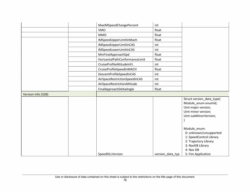
Use or disclosure of data contained on this sheet is subject to the restrictions on the title page of this document. 78
MaxIMSpeedChangePercent int VMO float MMO float IMSpeedUpperLimitInMach float IMSpeedUpperLimitInCAS int IMSpeedLowerLimitInCAS int MinFinalApproachSpd float HorizantalPathConformanceLimit float CruiseProfileAltitudeInFL int CruiseProfileSpeedInMACH float DescentProfileSpeedInCAS int AirSpaceRestrictionSpeedInCAS int AirSpaceRestrictionAltitude int FinalApproachDeltaAngle float Version Info (328)
SpeedDLLVersion version_data_typ
Struct version_data_type{ Module_enum enumId; Uint major version; Uint minor version; Uint subMinorVersion; } Module_enum: 0: unknown/unsupported 1: SpeedControl Library 2: Trajectory Library 3: NavDB Library 4: Nav DB 5: Fim Application

Use or disclosure of data contained on this sheet is subject to the restrictions on the title page of this document. 79
TrajDLLVersion version_data_typ See above
NavDBDLLVersion version_data_typ See above
NAVDBVersion version_data_typ See above
FIMAppVersion version_data_typ See above
Application Start Time (334) day uchar month uchar year uint hour uchar minute uchar epochInSec uint epochInMilisec uint OwnshipEnrty (336) DestinationAirport uchar[24] String name Runway uchar[24] String name
Use or disclosure of data contained on this sheet is subject to the restrictions on the title page of this document. 80
CruiseProfileAltitude int feet CruiseProfileSpeed float Mach DescentProfileSpeed int Cas DirectToPoint char[24] CruiseWindsEntry (337) WaypointIdent uchar[32] String name Direction int degrees Speed int kts DescentWindsEntry (338) Altitude int ft Direction int degrees Speed int kts IMClearanceEntry (339)
IMClearanceType uint enum { eIMNone, eIMCapture, eIMCross, eIMMaintain, eIMSpacing };
SpacingGoalUnit uint enum { eSECONDS, eMILES };
SpacingGoalVal float Seconds or miles (per above)
Use or disclosure of data contained on this sheet is subject to the restrictions on the title page of this document. 81
TargetIdent uchar[9] String id
AcheiveByType uint enum { eSelect, eDefault, eWPT, eAfter, eBefore }
AcheiveByRange float Nm
AcheiveByWaypoint uchar[32] String ident
TerminateAtType uint enum { eSelect, eDefault, eWPT, eAfter, eBefore }
TerminateAtRange float

Use or disclosure of data contained on this sheet is subject to the restrictions on the title page of this document. 82
TerminateAtWaypoint uchar[32] String ident allign uchar[3] n/a
OwnshipWaypointList (340) waypoint uchar[24] String ident IMSpeedSettingsEntry (341) IMSpeedUpperLimitMach float Mach IMSpeedUpperLimitCAS int kts IMSpeedLowerLimitCAS int kts
IMSpeedUnit enum { enMACH, enCAS, enDEFAULT, }
AirSpeedRestriction int kts AltitudeRestriction int ft NavDBSettingsEntry (342)

Use or disclosure of data contained on this sheet is subject to the restrictions on the title page of this document. 83
NavDBCurrentCycle enum
{ eFIRSTCYCLE = 0, eSECONDCYCLE = 1 }
EffectiveStartDate struct St_DateType - typedef struct { int nDay; int nMonth; int nYear; }St_DateType
EffectiveEndDate struct
St_DateType - typedef struct { int nDay; int nMonth; int nYear; }St_DateType
OwnshipFlightPath (345) FlightPath uchar[488] String list of nav points
TargetFlightPath (346)
FlightPath uchar[488]
String list of nav points ThreadTime(347) IOThreadEntryTime uint millisecond NumberOfEntriesPerSecIO uint n/a

Use or disclosure of data contained on this sheet is subject to the restrictions on the title page of this document. 84
BuildThreadEntryTime uint millisecond NumberOfEntriesPerSecBuild uint n/a TGSCThreadEntryTime uint millisecond NumberOfEntriesPerSecTGSC uint n/a DisplayThreadEntryTime uint millisecond NumberOfEntriesPerSecDisplay uint n/a TrafficData(348) timeFrame double sec trfcNumber uint(short) n/a
relAltStatusT2 Enum(uint)
eInValid, /* 0 - Invalid */ eValid /* 1 - Valid
bearingStatus uint
0 - Invalid 1 - Valid
vertSpdStatus uint trackAngleStatus uint gndSpdStatus uint
Use or disclosure of data contained on this sheet is subject to the restrictions on the title page of this document. 85
closureRateStatus uint

Use or disclosure of data contained on this sheet is subject to the restrictions on the title page of this document. 86
advisory uint
0 - Non Threat 1 - Traffic Advisory
2 - Resloution Advisory 3 - Proximate Traffic
4 - Reserved 5 - Reserved 6 - Reserved 7 - Reserved
8 - Airborne Military Target 9 - Reserved Military Target
10 - Reserved Military Target 11 - Reserved Military Target 12 - Reserved Military Target 13 - Reserved Military Target 14 - Reserved Military Target 15 - Reserved Military Target
0 - Invalid 1 - TCAS
2 - ADS-B 3 - ADS-R 4 - TIS-B
5 - Reserved 6 - Reserved
7 - Multi-Source Traffic Data
0 - Airborne 1 - Ground
trfcSource uint onGround uint flightID[9] uchar
trfcRange Float

Use or disclosure of data contained on this sheet is subject to the restrictions on the title page of this document. 87
trfcBearing Float degrees
lat float
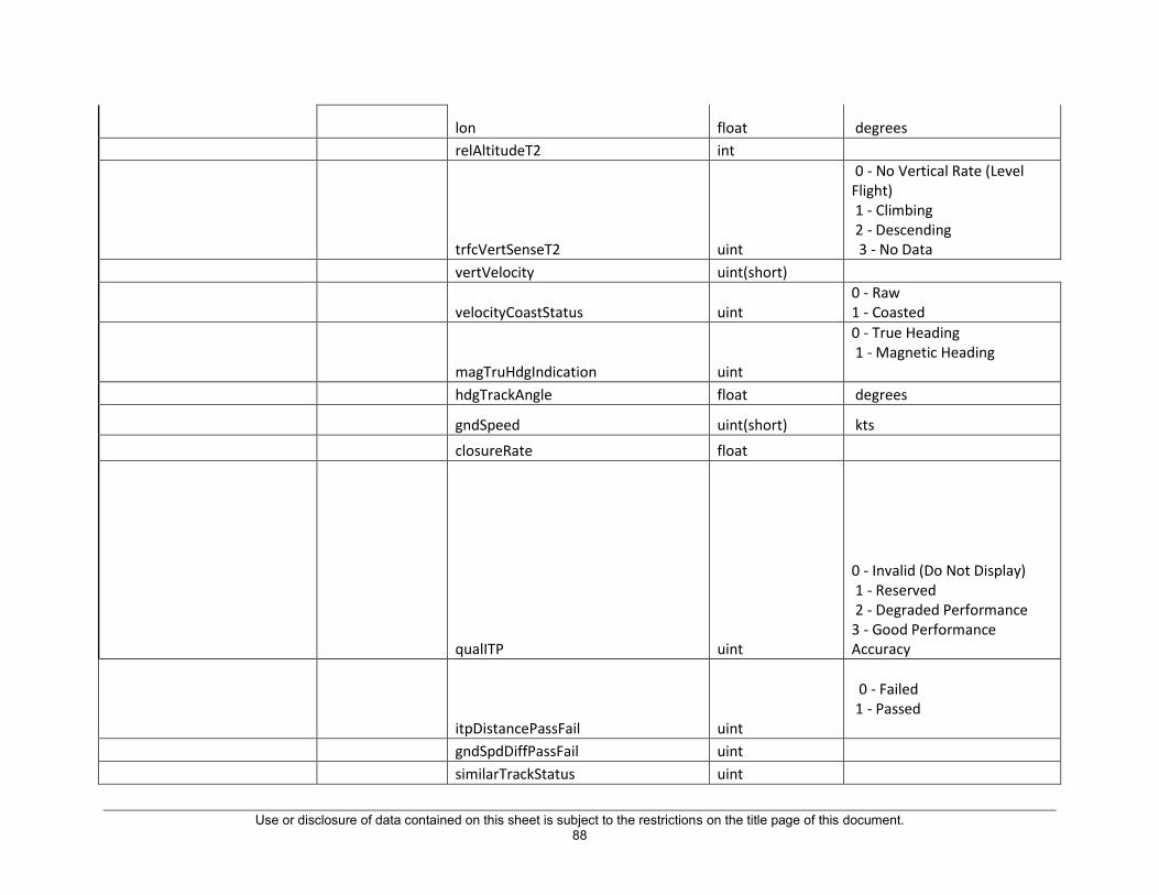
Use or disclosure of data contained on this sheet is subject to the restrictions on the title page of this document. 88
lon float degrees relAltitudeT2 int
trfcVertSenseT2 uint
0 - No Vertical Rate (Level Flight) 1 - Climbing 2 - Descending 3 - No Data
vertVelocity uint(short)
velocityCoastStatus uint 0 - Raw 1 - Coasted
magTruHdgIndication uint
0 - True Heading 1 - Magnetic Heading
hdgTrackAngle float degrees
gndSpeed uint(short) kts closureRate float
qualITP uint
0 - Invalid (Do Not Display) 1 - Reserved 2 - Degraded Performance 3 - Good Performance Accuracy
itpDistancePassFail uint
0 - Failed 1 - Passed
gndSpdDiffPassFail uint similarTrackStatus uint
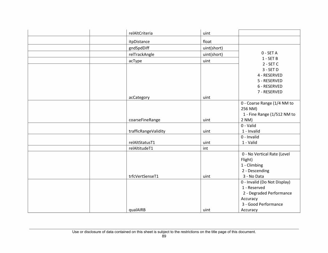
Use or disclosure of data contained on this sheet is subject to the restrictions on the title page of this document. 89
relAltCriteria uint
itpDistance float gndSpdDiff uint(short)
0 - SET A 1 - SET B 2 - SET C 3 - SET D
4 - RESERVED 5 - RESERVED 6 - RESERVED 7 - RESERVED
relTrackAngle uint(short) acType uint
acCategory uint
coarseFineRange uint
0 - Coarse Range (1/4 NM to 256 NM) 1 - Fine Range (1/512 NM to 2 NM)
trafficRangeValidity uint 0 - Valid 1 - Invalid
relAltStatusT1 uint 0 - Invalid 1 - Valid
relAltitudeT1 int
trfcVertSenseT1 uint
0 - No Vertical Rate (Level Flight) 1 - Climbing 2 - Descending 3 - No Data
qualAIRB uint
0 - Invalid (Do Not Display) 1 - Reserved 2 - Degraded Performance Accuracy 3 - Good Performance Accuracy

Use or disclosure of data contained on this sheet is subject to the restrictions on the title page of this document. 90
qualSURF uint
typedef enum { eValidRev, /* 0 - Valid */ eInValidRev /* 1 - Invalid */ }
qualIM uint
0 - Invalid 1 - Valid
qualTSAA uint
qualACM uint
0 - No Vertical Rate (Level Flight) 1 - Climbing 2 - Descending 3 - No Data
qualVSA uint 0 - Invalid (Do Not Display) 1 - Reserved
2 - Degraded Performance Accuracy
3 - Good Performance Accuracy
0 - extended beyond length/width
1 - matches length/width
posOffsetApplied uint width uint length uint lengthWidthStatus uint
nUTCSeconds int nUTCMinutes int

Use or disclosure of data contained on this sheet is subject to the restrictions on the title page of this document. 91
nUTCHours int

Use or disclosure of data contained on this sheet is subject to the restrictions on the title page of this document. 92
dUTCFineSeconds double
timeOfApplicability uint 0 - Valid 1 - InValid

Use or disclosure of data contained on this sheet is subject to the restrictions on the title page of this document. 93
Speed Control
Structure Name Msg Version Field Data Type Units
Speed Control State (Msg 321) 0
RecID short (uint16)

Use or disclosure of data contained on this sheet is subject to the restrictions on the title page of this document. 94
IM_State enum (uint)
OFF_TERMINATE=1, ARMED=2, AVAILABLE=3, SUSPEND_ARMED=4, SUSPEND_AVAILABLE=5, PAIRED=6, UNABLE=7
IMClearanceType enum (uint)
MAINTAIN=1, CAPTURE, CROSS, SPACE, NONE
SpeedControlState bool (uchar)
ABPMonitor enum (uint) abpPassed=1, abpNotPassed=2
PTPMonitor enum (uint) ptpReached=1, ptpNotReached=2
ASGValidForMaintClr bool (uchar)
ASGComputedForMaintClr bool (uchar)
alignment uchar[3]
TBO Control Law (Msg 322) 0
RecID short (uint16)
SCSystemTimeInSec double Sec
FirstCycle bool (uchar)

Use or disclosure of data contained on this sheet is subject to the restrictions on the title page of this document. 95
ASG float
ASGUnits enum(uint)
asguSEC=1, asguNM, asguINVALID
QuantizationSpeedLimit float Kts
SegZone enum (uint)
segzoneINVALID=0, segzoneAtRollIn=1, segzoneDuringRollIn, segzoneLookAhead, segzoneUnrestricted
SegType enum (uint)
stypeLevel, stypeAccel, stypeDecel, stypeINVALID
RollInCount int LookAheadDuration int Secs SpacingInterval float Nm/sec SpacingIntervalStatus enum(uint) scINVALID=1, scVALID SpacingErrorInSecs int Nm/sec SpacingErrorFP float Nm/sec
ProgressIndicatorStatus enum(uint) piOFF=1, piON
EarlyLateIndicatorScale enum(uint)
els45SEC=1, els120SEC, elsINVALID
GSCTau float sec
GSCoastedState enum csNonCoasted=1, csCoasted
GSCDeltaTime int GSC2Tau float sec

Use or disclosure of data contained on this sheet is subject to the restrictions on the title page of this document. 96
GSCFilterInput float Kts GSCGndSpdCompTerm float Kts GSCGndSpdCompFilter float kts GSCGainLimit float GSCSpeedErrorCompensation float Kts GainforSpeedError float SpeedError float Kts VmoLimit float Kts MMOLimitInMach float MMOLimitInKts float Kts IMSpeedUpperLimitInKts float Kts IMSpeedUpperLimitInMach float Mach IMSpeedUpperLimitAsMachInKts float Kts SelIMSpeedUpperLimitInKts float Kts ArspcAirspaceRestrictionAltInFt double Feet ArspcRateInKtsPerSec float kts/sec ArspcTimeNeededToReduceSpeed float Sec ArspcSmallerTimeNeeded float Sec ArspcOwnshipEstimatedVerticalRateInFps float Fps ArspcDerivedAltInFt float Feet
ArspcsrState enum (uint) INACTIVE:1, ACTIVE:0
ArspcRestrictionLimitInKts float kts
RFUpcomingRFRestrictedLeg bool (uchar)
RFActiveRFRestrictedLeg bool (uchar)
RFOwnshipDTGToStartOfRFLeg float NM RFRestrictedSpeedForUpcomingRFLeg float kts RFRateInKtsPerSec float Kts/sec

Use or disclosure of data contained on this sheet is subject to the restrictions on the title page of this document. 97
RFTimeNeededToReduceSpeed float Sec RFEstDTGToStartOfRFLeg float NM RFOwnshipEstimatedGroundSpeedInKts float kts RFRestrictionLimitInKts float kts
RFSpeedRestrictionState enum (uint) INACTIVE:1, ACTIVE:0
CtrlLawRestrictionState enum (uint) CtrlLawRestrictionLimitInKts float Kts
CtrlLawSelectedSpeedRestriction enum (uint)
spNomProfileUprLmt, spVmoUprLmt, spMmoUprLmt, spIMSpdUprLmt, spAirSpcRestrUprLmt, spRFSpdRestrUprLmt, spNomProfileLwrLmt, spIMSpdLwrLmt, pMinFASLwrLmt
CtrlLawTimeUntilCrossing float Sec CtrlLawTimeUntilStartOfLeg float Sec CtrlLawRemainingSpeedReductionForAirspace float Kts CtrlLawRemainingSpeedReductionForRF float Kts CtrlLawSpdRestrictionDecelRate float NomProfUpperSpdLimitInKts float Kts NomProfLowerSpdLimitInKts float Kts IMSpeedLowerLimitinKts float Kts

Use or disclosure of data contained on this sheet is subject to the restrictions on the title page of this document. 98
SelectedUpperSpeedLimit enum (uint)
spNomProfileUprLmt, spVmoUprLmt, spMmoUprLmt, spIMSpdUprLmt, spAirSpcRestrUprLmt, spRFSpdRestrUprLmt, spNomProfileLwrLmt, spIMSpdLwrLmt, pMinFASLwrLmt
SelectedLowerSpeedLimit enum (uint)
spNomProfileUprLmt, spVmoUprLmt, spMmoUprLmt, spIMSpdUprLmt, spAirSpcRestrUprLmt, spRFSpdRestrUprLmt, spNomProfileLwrLmt, spIMSpdLwrLmt, pMinFASLwrLmt
AppliedSpeedLimit enum (uint)
spNomProfileUprLmt, spVmoUprLmt, spMmoUprLmt, spIMSpdUprLmt, spAirSpcRestrUprLmt, spRFSpdRestrUprLmt, spNomProfileLwrLmt, spIMSpdLwrLmt, pMinFASLwrLmt
SpeedLimited bool (uchar)
IsUprSpdLmtApplied bool (uchar)

Use or disclosure of data contained on this sheet is subject to the restrictions on the title page of this document. 99
SpeedCorrection float Kts OwnshipCurrSegEndSpdInKts float Kts OwnshipNextSegEndSpdInKts float Kts DTGInNm float NM IMCommandedSpeedInKts float Kts SpdInMachBeforeRoundup float IMCommandedSpeedInMach float IMSpeedUnits enum(uint) imsouKNOTS=1, imsouMACH IMSpeedStatus enum(uint) scINVALID=1, scVALID
InstSpdInputSource enum(uint)
tboISISNotUpdated, tboISISSpeedRate, tboISISSpeedRestrictionDecelRate, tboISISSpeedCorrProfileCAS, tboISISRollInProfileCAS, tboISISFASInterceptProfile
IMInstantaneousSpeed float InstSpdCorrectionInput float kts InstSpdDecelCeiling float kts LastInstSpdSpeedCorrProfileCAS float kts InstSpdSpeedCorrProfileCAS float kts InstSpdTermA float InstSpdFOFTimeConstant float InstSpdRollInProfileCAS float kts InstSpdOwnshipAtRollInCAS float kts InstSpdRollInSpeedDiff float kts
CurrSegType enum (uint)
stypeLevel:0, stypeAccel, stypeDecel
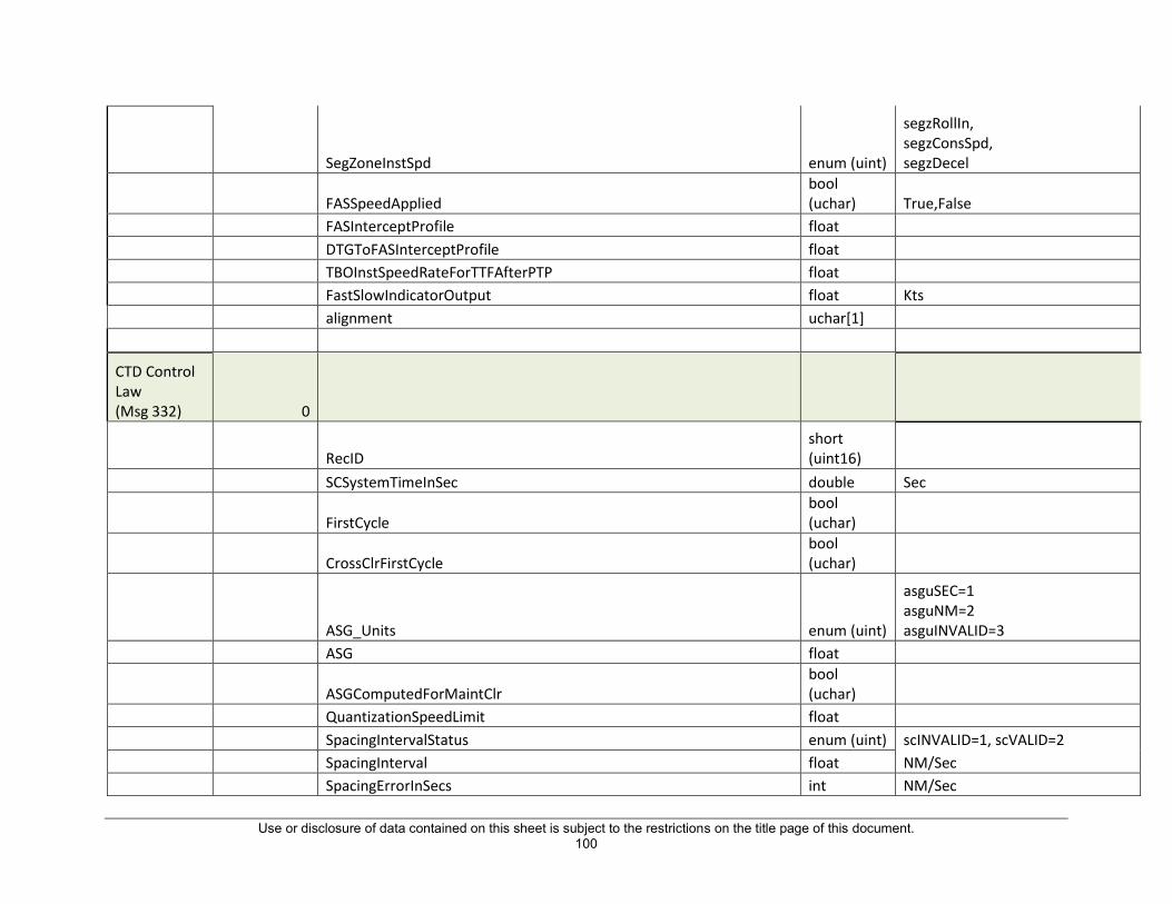
Use or disclosure of data contained on this sheet is subject to the restrictions on the title page of this document. 100
SegZoneInstSpd enum (uint)
segzRollIn, segzConsSpd, segzDecel
FASSpeedApplied bool (uchar) True,False
FASInterceptProfile float DTGToFASInterceptProfile float TBOInstSpeedRateForTTFAfterPTP float FastSlowIndicatorOutput float Kts alignment uchar[1]
CTD Control Law (Msg 332) 0
RecID short (uint16)
SCSystemTimeInSec double Sec
FirstCycle bool (uchar)
CrossClrFirstCycle bool (uchar)
ASG_Units enum (uint)
asguSEC=1 asguNM=2 asguINVALID=3
ASG float
ASGComputedForMaintClr bool (uchar)
QuantizationSpeedLimit float SpacingIntervalStatus enum (uint) scINVALID=1, scVALID=2 SpacingInterval float NM/Sec SpacingErrorInSecs int NM/Sec

Use or disclosure of data contained on this sheet is subject to the restrictions on the title page of this document. 101
SpacingErrorFP float NM/Sec TimeAtASGBehindTTFPos double Sec TimeAtOwnToTTFDistBehindTTFPos double Sec GainforSpeedError float SpeedError float Kts
MinCaptureRate bool (uchar)
ProgressIndicatorStatus enum (uint) piOFF=1, piON
EarlyLateIndicatorScale enum (uint)
els45SEC=1, els120SEC, elsINVALID
VmoLimit float Kts MMOLimitInMach float Kts MMOLimitInKts float Kts IMSpeedUpperLimitInKts float Kts IMSpeedUpperLimitInMach float Mach IMSpeedUpperLimitAsMachInKts float kts SelIMSpeedUpperLimitInKts float kts ArspcAirspaceRestrictionAltInFt double Feet ArspcRateInKtsPerSec float kts/sec ArspcTimeNeededToReduceSpeed float Sec ArspcSmallerTimeNeeded float Sec
ArspcOwnshipEstimatedVerticalRateInFps float Fps ArspcDerivedAltInFt float Feet
ArspcsrState enum (uint) INACTIVE:1, ACTIVE:0
ArspcRestrictionLimitInKts float kts

Use or disclosure of data contained on this sheet is subject to the restrictions on the title page of this document. 102
RFUpcomingRFRestrictedLeg bool (uchar)
RFActiveRFRestrictedLeg bool (uchar)
RFOwnshipDTGToStartOfRFLeg float NM RFRestrictedSpeedForUpcomingRFLeg float kts RFRateInKtsPerSec float kts/sec RFTimeNeededToReduceSpeed float Sec RFEstDTGToStartOfRFLeg float NM RFOwnshipEstimatedGroundSpeedInKts float kts RFRestrictionLimitInKts float kts
RFSpeedRestrictionState enum (uint) INACTIVE:1, ACTIVE:0
CtrlLawRestrictionState enum (uint) INACTIVE:1, ACTIVE:0
CtrlLawRestrictionLimitInKts float Kts
CtrlLawSelectedSpeedRestriction enum (uint)
spNomProfileUprLmt, spVmoUprLmt, spMmoUprLmt, spIMSpdUprLmt, spAirSpcRestrUprLmt, spRFSpdRestrUprLmt, spNomProfileLwrLmt, spIMSpdLwrLmt, pMinFASLwrLmt
CtrlLawTimeUntilCrossing float Sec CtrlLawTimeUntilStartOfLeg float Sec
CtrlLawRemainingSpeedReductionForAirspace float Kts CtrlLawRemainingSpeedReductionForRF float Kts CtrlLawSpdRestrictionDecelRate float

Use or disclosure of data contained on this sheet is subject to the restrictions on the title page of this document. 103
NomProfUpperSpdLimitInKts float Kts NomProfLowerSpdLimitInKts float Kts IMSpeedLowerLimitinKts float Kts
SelectedUpperSpeedLimit enum (uint)
spNomProfileUprLmt, spVmoUprLmt, spMmoUprLmt, spIMSpdUprLmt, spAirSpcRestrUprLmt, spRFSpdRestrUprLmt, spNomProfileLwrLmt, spIMSpdLwrLmt, pMinFASLwrLmt
SelectedLowerSpeedLimit enum (uint)
spNomProfileUprLmt, spVmoUprLmt, spMmoUprLmt, spIMSpdUprLmt, spAirSpcRestrUprLmt, spRFSpdRestrUprLmt, spNomProfileLwrLmt, spIMSpdLwrLmt, pMinFASLwrLmt
AppliedSpeedLimit enum (uint)
spNomProfileUprLmt, spVmoUprLmt, spMmoUprLmt, spIMSpdUprLmt, spAirSpcRestrUprLmt, spRFSpdRestrUprLmt, spNomProfileLwrLmt, spIMSpdLwrLmt, pMinFASLwrLmt

Use or disclosure of data contained on this sheet is subject to the restrictions on the title page of this document. 104
SpeedLimited bool (uchar)
IsUprSpdLmtApplied bool (uchar)
IMCommandedSpeedInKts float Kts SpdInMachBeforeRoundup float IMCommandedSpeedInMach float Mach IMSpeedUnits enum (uint) imsouKNOTS=1, imsouMACH IMSpeedStatus enum (uint) scINVALID=1, scVALID TgtHistCASAt15SecLeadFromOwnship float CTDProfileCAS float
CTDDecelIndication bool (uchar)
TTFTOADecelSegEnd float OwnshipDecelEndSpeed float LastIMSpeedElapsedCycleCount int LockoutCounter int
DecelLockout enum (uint)
decelLOCK, decelUNLOCK, decelINVALID
RoundEndCAS2ktsPosBiasCorrection float Kts RoundCAS2ktsPosBiasCorrection float Kts Round15sLeadCAS5ktsPosBiasCorrection float Kts Round15sLeadCAS2ktsPosBiasCorrection float Kts RoundCAS2ktsPosBias float kts Round15sLeadCAS2ktsPosBias float kts CAS2ktsNegBiasWithCorrection float kts
FiveDecel bool (uchar)
TwoDecel bool (uchar)

Use or disclosure of data contained on this sheet is subject to the restrictions on the title page of this document. 105
FiveAccel bool (uchar)
TwoAccel bool (uchar)
InstSpdInputSource enum(uint)
ctdISISNotUpdated, ctdISISSpeedRate, ctdISISSpeedRestrictionDecelRate
IMInstantaneousSpeed float CTDInstSpeedRate float SpeedChange float kts SegmentLength float Sec FastSlowIndicatorOutput float alignment uchar[1]
Speed Conformance Monitor (Msg 323) 0
RecID short (uint16)
SCM_State enum (uint) scmInactive:1, scmActive:2
SegType enum (uint)
stypeLevel:0, stypeAccel, stypeDecel
CommandedIMSpd float Kts NewIMSpeedFirstCAS float Kts NewIMSpeedFirstMach float Mach NoOfCycle int ExpectedCAS float Kts

Use or disclosure of data contained on this sheet is subject to the restrictions on the title page of this document. 106
ExpectedMACH float Mach
SpdConformance enum (uint) InConformance=1, OutOfConformance=2
OwnshipCASInKts float Kts OwnshipMach float Mach alignment uchar[2] TG IM Record (Msg 333)
RecID short (uint16)
OwnToTTF_DTG float NM OwnToTTF_TTG float Secs OwnToABP_DTG float NM OwnToABP_TTG double Secs OwnToPTP_DTG float NM OwnToPTP_TTG double Secs TTFToABP_DTG float NM TTFToABP_TTG double Secs TTFToPTP_DTG float NM TTFToPTP_TTG double Secs Owniship_Vertical_Deviation float TTF_Vertical_Deviation float Owniship_Lateral_Deviation float TTF_Lateral_Deviation float OwnshipLeadSpeed_3SECS float OwnshipLeadSpeed_27SECS float CurrentOwnshipState_CAS float Kts CurrentOwnshipState_GroundSpeed float Kts

Use or disclosure of data contained on this sheet is subject to the restrictions on the title page of this document. 107
CurrentOwnshipState_CrossoverAlt float kts CurrentOwnshipState_Latitude float deg CurrentOwnshipState_Longitude float deg
CurrentOwnshipState_SpeedType enum (uint)
CAS_e = 0, MACH_e, TAS_e, GROUND_SPEED_e
CurrentTTFState_CAS float Kts CurrentTTFState_GroundSpeed float Kts CurrentTTFState_CrossoverAlt float Kts CurrentTTFState_Latitude float deg CurrentTTFState_Longitude float deg
CurrentTTFState_SpeedType enum (uint)
CAS_e = 0, MACH_e, TAS_e, GROUND_SPEED_e
OwnshipCurrentSegmentSpeedRecord_SegmentSpeed float Kts
OwnshipCurrentSegmentSpeedRecord_EnrouteTimeSegmentEndPoint float Kts
OwnshipCurrentSegmentSpeedRecord_SegmentSpeedType enum (uint)
CAS_e = 0, MACH_e, TAS_e, GROUND_SPEED_e
OwnshipNextSegmentSpeedRecord_SegmentSpeed float Secs
OwnshipNextSegmentSpeedRecord_SegmentSpeedType enum (uint)
CAS_e = 0, MACH_e, TAS_e, GROUND_SPEED_e
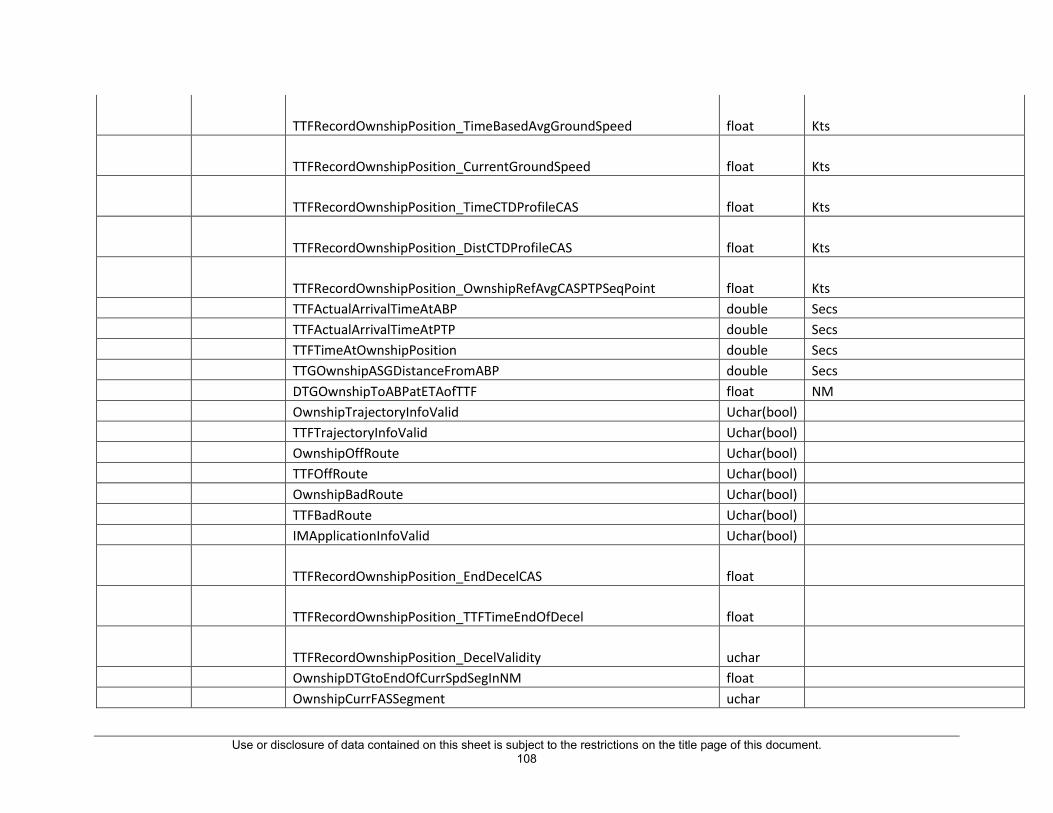
Use or disclosure of data contained on this sheet is subject to the restrictions on the title page of this document. 108
TTFRecordOwnshipPosition_TimeBasedAvgGroundSpeed float Kts
TTFRecordOwnshipPosition_CurrentGroundSpeed float Kts
TTFRecordOwnshipPosition_TimeCTDProfileCAS float Kts
TTFRecordOwnshipPosition_DistCTDProfileCAS float Kts
TTFRecordOwnshipPosition_OwnshipRefAvgCASPTPSeqPoint float Kts TTFActualArrivalTimeAtABP double Secs TTFActualArrivalTimeAtPTP double Secs TTFTimeAtOwnshipPosition double Secs TTGOwnshipASGDistanceFromABP double Secs DTGOwnshipToABPatETAofTTF float NM OwnshipTrajectoryInfoValid Uchar(bool) TTFTrajectoryInfoValid Uchar(bool) OwnshipOffRoute Uchar(bool) TTFOffRoute Uchar(bool) OwnshipBadRoute Uchar(bool) TTFBadRoute Uchar(bool) IMApplicationInfoValid Uchar(bool)
TTFRecordOwnshipPosition_EndDecelCAS float
TTFRecordOwnshipPosition_TTFTimeEndOfDecel float
TTFRecordOwnshipPosition_DecelValidity uchar OwnshipDTGtoEndOfCurrSpdSegInNM float OwnshipCurrFASSegment uchar

Use or disclosure of data contained on this sheet is subject to the restrictions on the title page of this document. 109
OwnshipNextFASSegment uchar
SpeedRestrictionRecord_NominalDecelRateSpeedLimit float
SpeedRestrictionRecord_DownpathRFMostRestrSpeedValidity uchar
SpeedRestrictionRecord_DownpathRFMostRestrSpeed float
SpeedRestrictionRecord_DTGStartOfRFLeg float
SpeedRestrictionRecord_ActiveRFMostRestrSpeedValidity uchar
SpeedRestrictionRecord_ActiveRFMostRestrSpeed float NomCASAtEndOfDecel float OwnshipDeltaCASPerNM float alignment uchar[2]
Trajectory Generator
Structure Name Msg Version Field Data Type Units
Vertical And Lateral TCP(msg 329) 0
planId enum(uInt) OWNSHIP_e = 0 TARGET_e =1

Use or disclosure of data contained on this sheet is subject to the restrictions on the title page of this document. 110
TCPType bool (uchar) TRUE = Lateral TCP FALSE = Vertical TCP
TGGenerationReason enum(uInt)
INITIAL_TRAJECTORY_e = 0 WIND_DEV_e = 1 VERTICAL_DEV_e = 2
Vertical TCP nomPathAlt float feet
waypointIdentity uChar[24] nomGndSpeed float Kts nomCASorMach float Kts nomTrueAirspeed float Kts forecastWindVec float Kts forecastWindDirection float Degrees predictedWind float Kts predictedWindDirection float Degrees forecastTemp float Centigrade speedErrorValue float Kts
speedSegmentErrorReason enum(uInt)
NO_ERROR_e = 0, SPEED_ERROR_e = 1, ALTITUDE_ERROR_e = 2
altitudeErrorValue float feet
altitudeSegmentErrorReason enum(uInt)
NO_ERROR_e = 0, SPEED_ERROR_e = 1, ALTITUDE_ERROR_e = 2
Lateral/Horizontal TCP ABPValidity bool(uchar)
TRUE = Valid ABP FALSE = INVALID ABP

Use or disclosure of data contained on this sheet is subject to the restrictions on the title page of this document. 111
segmentType enum(uInt) Straight = 0 Trun = 1
distanceToGoPTP float NM distanceToGoABP float NM turnRadius float NM course float Degrees latitude float Degrees longitude float Degrees timeToGoABP double Time in seconds (Epoch) timeToGoPTP double Time in seconds (Epoch)
unitX double Meters unitY double Meters unitZ double Meters alignment uchar[2]
Flight Plan Waypoints (Msg 330) -
planId enum(uInt) OWNSHIP_e = 0, TARGET_e
waypointIdentity uChar[24] waypointLatitude float Degrees waypointLongitude float Degrees waypointAltitudeConstraintLower float feet
waypointAltitudeConstraintLowerValidity enum(uInt) VALID_e = 0 INVALID_e = 1
waypointAltitudeConstraintLowerType enum(uInt) AA_e = 0, AB_e=1, AT=2

Use or disclosure of data contained on this sheet is subject to the restrictions on the title page of this document. 112
waypointAltitudeConstraintLowerSourceType enum(uInt)
ST_NO_SOURCE_e =0, ST_COMPUTED_e = 1 ST_DEFAULT_e = 2 ST_DATABASE_e = 3
waypointAltitudeConstraintUpper float feet
waypointAltitudeConstraintUpperValidity enum(uInt) VALID_e = 0 INVALID_e = 1
waypointAltitudeConstraintUpperType enum(uInt) AA_e = 0, AB_e=1, AT=2
waypointAltitudeConstraintUpperSourceType enum(uInt)
ST_NO_SOURCE_e =0, ST_COMPUTED_e = 1 ST_DEFAULT_e = 2 ST_DATABASE_e = 3
waypointSpeedConstraint float Kts
waypointSpeedConstraintValidity enum(uInt) VALID_e = 0 INVALID_e = 1
waypointSpeedConstraintSourceType enum(uInt)
ST_NO_SOURCE_e =0, ST_COMPUTED_e = 1 ST_DEFAULT_e = 2 ST_DATABASE_e = 3
waypointFPA float Degrees
waypointFPAValidity enum(uInt) VALID_e = 0 INVALID_e = 1
waypointWindSpeed float Kts waypointWindDirection float Degrees waypointWindAltitude float feet temperature float Centigrade waypointTurnRadius float NM waypointTurnCenterLat float Degrees waypointTurnCenterLon float Degrees

Use or disclosure of data contained on this sheet is subject to the restrictions on the title page of this document. 113
TG Perf data (Msg 331) 0
planId enum(uInt) OWNSHIP_e = 0, TARGET_e
cruiseAltitude float feet
cruiseAltitudeValidity enum(uInt) DATA_VALID_e = 0 , DATA_INVALID_e = 1
cruiseCAS float Kts
cruiseCASValidity enum(uInt) DATA_VALID_e = 0 , DATA_INVALID_e = 1
cruiseMach float Mach number
cruiseMachValidity enum(uInt) DATA_VALID_e = 0 , DATA_INVALID_e = 1
descentCAS float Kts
descentCASValidity enum(uInt) DATA_VALID_e = 0 , DATA_INVALID_e = 1
descentMach float Mach number
descentMachValidity enum(uInt) DATA_VALID_e = 0 , DATA_INVALID_e = 1
TG Forecast Wind data (Msg 335) 0
planId enum(uInt) OWNSHIP_e = 0, TARGET_e
waypointIdentity uChar[24] forecastWindMag float Kts forecastWindDirection float Degrees forecastWindAlt float feet

Use or disclosure of data contained on this sheet is subject to the restrictions on the title page of this document. 114
TG Discoery data (Msg 343) 0
discoveryAlgoStatus bool(uchar) TRUE = Success FALSE = Failure
metaPhase enum(uInt) NO_PHASE_e = 0, CRUISE_e = 1, DESCENT_e = 2
cruiseAltitude float feet
cruiseAltitudeValidity enum(uInt) DATA_VALID_e = 0 , DATA_INVALID_e = 1
cruiseCAS float Kts
cruiseCASValidity enum(uInt) DATA_VALID_e = 0 , DATA_INVALID_e = 1
cruiseMach float Mach number
cruiseMachValidity enum(uInt) DATA_VALID_e = 0 , DATA_INVALID_e = 1
descentCAS float Kts
descentCASValidity enum(uInt) DATA_VALID_e = 0 , DATA_INVALID_e = 1
descentMach float Mach number
descentMachValidity enum(uInt) DATA_VALID_e = 0 , DATA_INVALID_e = 1
alignment uchar[3]
TG Traffic records (Msg 344) 0 timeFrame double Time in seconds (Epoch) flightId uchar[9]

Use or disclosure of data contained on this sheet is subject to the restrictions on the title page of this document. 115
trackId uint latitude float Degrees longitude float Degrees altitude float feet groundSpeed float Kts trackAngle float Degrees rawValue uint
VelocityCoastStatus enum(uint) RAW_e = 0, COASTED_e = 1
alignment uchar[3]
End of decel Computation Data (Msg 349) 0 trafficTimeFrame double Time in seconds (Epoch) ownshipTrack; double degrees ownshipWindSpeedKnots double kts ownshipWindDirectionDegrees double degrees ownshipAlt double feet ownshipISADev; double Degree celcius trafficAltitudeAtOwnhipPositon float feet speed1 float kts
speed1Validity enum(uint) EOD_DATA_INVALID_e = 0, EOD_DATA_VALID_e = 1
speed2 float kts

Use or disclosure of data contained on this sheet is subject to the restrictions on the title page of this document. 116
speed2Validity enum(uint) EOD_DATA_INVALID_e = 0, EOD_DATA_VALID_e = 1
speed3 float kts
speed3Validity enum(uint) EOD_DATA_INVALID_e = 0, EOD_DATA_VALID_e = 1
speed4 float kts
speed4Validity enum(uint) EOD_DATA_INVALID_e = 0, EOD_DATA_VALID_e = 1
avgGroundSpeed float kts trafficTrack double degrees trafficAlt double feet testCAS float kts testTimeStamp double Time in seconds (Epoch) endOfDecel float kts endOfDecelTime double Time in seconds (Epoch)
result enum(uint)
INIT_e = 0, EOD_DEFAULT_e = 1, FOURTY_SEC_LAPSED_e = 2, END_OF_TRAFFIC_RECORD_e = 3, ACCEL_SEG_e = 4, DECEL_SEG_e = 5

Use or disclosure of data contained on this sheet is subject to the restrictions on the title page of this document. 117

Use or disclosure of data contained on this sheet is subject to the restrictions on the title page of this document.
118
6.0 SPEED CONTROL SOURCE
This section has been redacted to comply with the Intellectual Property clause of the contract.
.

Use or disclosure of data contained on this sheet is subject to the restrictions on the title page of this document. 119
7.0 ACRONYMS
AID Aircraft Interface Device
FIM Flight Deck Interval Management
NDB Navigation Database module
SC Speed Control module
STAP Simple Text Avionics Protocol
TG Tragectory Generator module
THDB Traffic History Database
TTF Traffic To Follow

REPORT DOCUMENTATION PAGE
Standard Form 298 (Rev. 8/98) Prescribed by ANSI Std. Z39.18
Form Approved OMB No. 0704-0188
The public reporting burden for this collection of information is estimated to average 1 hour per response, including the time for reviewing instructions, searching existing datasources, gathering and maintaining the data needed, and completing and reviewing the collection of information. Send comments regarding this burden estimate or any otheraspect of this collection of information, including suggestions for reducing the burden, to Department of Defense, Washington Headquarters Services, Directorate for InformationOperations and Reports (0704-0188), 1215 Jefferson Davis Highway, Suite 1204, Arlington, VA 22202-4302. Respondents should be aware that notwithstanding any otherprovision of law, no person shall be subject to any penalty for failing to comply with a collection of information if it does not display a currently valid OMB control number. PLEASE DO NOT RETURN YOUR FORM TO THE ABOVE ADDRESS.
1. REPORT DATE (DD-MM-YYYY) 2. REPORT TYPE 3. DATES COVERED (From - To)
4. TITLE AND SUBTITLE 5a. CONTRACT NUMBER
5b. GRANT NUMBER
5c. PROGRAM ELEMENT NUMBER
5d. PROJECT NUMBER
5e. TASK NUMBER
5f. WORK UNIT NUMBER
6. AUTHOR(S)
7. PERFORMING ORGANIZATION NAME(S) AND ADDRESS(ES) 8. PERFORMING ORGANIZATION REPORT NUMBER
10. SPONSOR/MONITOR'S ACRONYM(S)
11. SPONSOR/MONITOR'S REPORT NUMBER(S)
9. SPONSORING/MONITORING AGENCY NAME(S) AND ADDRESS(ES)
12. DISTRIBUTION/AVAILABILITY STATEMENT
13. SUPPLEMENTARY NOTES
14. ABSTRACT
15. SUBJECT TERMS
16. SECURITY CLASSIFICATION OF:
a. REPORT b. ABSTRACT c. THIS PAGE
17. LIMITATION OF ABSTRACT
18. NUMBER OF PAGES
19a. NAME OF RESPONSIBLE PERSON
19b. TELEPHONE NUMBER (Include area code)
(757) 864-9658
This document contains a summary of technical information relating to the Honeywell FIM software,TPU and system operation.
NASA Langley Research Center Hampton, VA 23681-2199
National Aeronautics and Space Administration Washington, DC 20546-0001
Unclassified - Unlimited Subject Category 03 Availability: NASA STI Program (757) 864-9658
NASA-CR-2017-219646
01- 07- 2017 Contractor Report
STI Help Desk (email: [email protected])
U U U UU
ATD-1; Airspace Managment; Aviation; FIM
FIM Avionics Technical Reference Manual
Schimmel, Craig
128
NASA
Langley Technical Monitor: Denise K. Scearce
NNL15AB46T
330693.04.10.07.09
NNL13AA03B