fim annual work schedule technical specifications · pdf filefim annual work schedule...
TRANSCRIPT


Foreword
2 FIM Annual Work Schedule Technical Specifications November 2009
Foreword
The Forest Information Manual (FIM) prescribes FIM technical specifications that describe
information standards. Technical specifications are prepared to facilitate the provision of information
prescribed by the FIM. They provide the direction for exchanging information between the MNR and
the forest industry. They provide detailed, technical and product specific requirements and outline
roles and responsibilities. The FIM technical specifications cover subjects such as:
• detailed data attribute descriptions
• acceptable file and media formats
• metadata requirements
• information exchange parameters and protocol
• standards/procedures for quality control, error handling, and verification
FIM technical specifications are effective upon regulation of the FIM or as they are developed.
Technical specifications may be revised periodically to consider more effective and efficient ways of
managing, transferring, and receiving information. Changes or revisions to technical specifications
do not impact the requirements or direction for the provision of information as prescribed by the FIM.
It is a requirement of the FIM that the FIM technical specifications (and revisions) be followed.
These FIM Annual Work Schedule Technical Specifications are prescribed by the Forest Information
Manual.
A list of current FIM technical specifications and the scope of information to which they apply will be
maintained and available on the Forest Information Portal(FI Portal). The MNR and forest industry
are required to use the technical specifications listed on the FI Portal.

Table of Contents
FIM Annual Work Schedule Technical Specifications 3 November 2009
Table of Contents
Foreword........................................................................................................................................ 2
1.0 Introduction........................................................................................................................... 7
2.0 Roles and Responsibilities .................................................................................................... 8 2.1 Licensee........................................................................................................................................... 8 2.2 Ministry of Natural Resources...................................................................................................... 8
3.0 Implementation ..................................................................................................................... 9 3.1 Revision Notes ................................................................................................................................ 9
4.0 Product Descriptions .......................................................................................................... 10 4.1 Water Crossing Review Results.................................................................................................. 10
4.1.1 Description, Intent and Intended Use................................................................................... 10 4.1.2 Packaging and Naming Convention..................................................................................... 10 4.1.3 Metadata............................................................................................................................... 10 4.1.4 Format .................................................................................................................................. 10 4.1.5 Data Transfer and Schedule ................................................................................................. 11
4.2 Scheduled Operations Spatial Information Specifications....................................................... 12 4.2.1 Description, Intent and Intended Use................................................................................... 12 4.2.2 Packaging and Naming Convention..................................................................................... 13 4.2.3 Metadata............................................................................................................................... 13 4.2.4 Format .................................................................................................................................. 13 4.2.5 Data Transfer and Schedule ................................................................................................. 14 4.2.6 Review and Approval........................................................................................................... 14 4.2.7 Scheduled Harvest Layer ..................................................................................................... 15 4.2.8 Areas of Concern in Scheduled Operations Layer ............................................................... 17 4.2.9 Scheduled Residual Patches Layer....................................................................................... 19 4.2.10 Scheduled Road Corridors Layer ......................................................................................... 21 4.2.11 Scheduled Operational Road Boundaries Layer .................................................................. 23 4.2.12 Scheduled Existing Road Activities Layer........................................................................... 25 4.2.13 Scheduled Water Crossing Activities Layer ........................................................................ 27 4.2.14 Scheduled Non-Water AOC Crossings ................................................................................ 29 4.2.15 Scheduled Aggregate Extraction Areas Layer ..................................................................... 31 4.2.16 Scheduled Site Preparation Treatments Layer ..................................................................... 33 4.2.17 Scheduled Regeneration Treatments Layer.......................................................................... 35 4.2.18 Scheduled Tending Treatments Layer ................................................................................. 37 4.2.19 Scheduled Protection Treatments Layer .............................................................................. 39 4.2.20 Existing Forestry Aggregate Pits Layer ............................................................................... 41
4.3 Map Specifications ....................................................................................................................... 43 4.3.1 Description, Intent and Intended Use................................................................................... 43 4.3.2 Packaging and Naming Convention..................................................................................... 43 4.3.3 Metadata............................................................................................................................... 45 4.3.4 Format .................................................................................................................................. 45 4.3.5 Public Notice Map ............................................................................................................... 50

Table of Contents
4 FIM Annual Work Schedule Technical Specifications November 2009
4.3.6 Annual Work Schedule Index Map...................................................................................... 52 4.3.7 Annual Work Schedule Operations Maps ............................................................................. 54 4.3.8 AWS Summary Map ............................................................................................................. 58
4.4 AWS Text and Tables.................................................................................................................. 60 4.4.1 Description, Intent and Intended Use................................................................................... 60 4.4.2 Packaging and Naming Convention..................................................................................... 60 4.4.3 Metadata............................................................................................................................... 61 4.4.4 Format .................................................................................................................................. 61 4.4.5 Data Transfer and Schedule ................................................................................................. 62 4.4.6 Review and Approval........................................................................................................... 62 4.4.7 AWS Text ............................................................................................................................ 62 4.4.8 Tables ................................................................................................................................... 62
5.0 Submission Files .................................................................................................................. 63 5.1 Description, Intent and Intended Use ........................................................................................ 63 5.2 Packaging and Naming Convention ........................................................................................... 64 5.3 Metadata ....................................................................................................................................... 64 5.4 Format........................................................................................................................................... 64 5.5 Data Transfer and Schedule ....................................................................................................... 65 5.6 Review and Approval .................................................................................................................. 65 5.7 Annual Work Schedules .............................................................................................................. 66
5.7.1 Description, Intent and Intended Use................................................................................... 66 5.7.2 Packaging and Naming Convention..................................................................................... 66 5.7.3 Folder Requirements ............................................................................................................ 66 5.7.4 Product Components ............................................................................................................ 67
5.8 AWS Changes............................................................................................................................... 69 5.8.1 Description, Intent and Intended Use................................................................................... 69 5.8.2 Packaging and Naming Convention..................................................................................... 69 5.8.3 Metadata............................................................................................................................... 73 5.8.4 Format .................................................................................................................................. 73 5.8.5 Data Transfer and Schedule ................................................................................................. 74 5.8.6 Review and Approval........................................................................................................... 74
Appendix 1 Tabular Attribute Descriptions........................................................................... 75 A1.1 Scheduled Harvest Layer ........................................................................................................ 75
A1.1.1 AWS_YR........................................................................................................................... 75 A1.1.2 SILVSYS ........................................................................................................................... 76 A1.1.3 HARVCAT........................................................................................................................ 76 A1.1.4 FUELWOOD..................................................................................................................... 77
A1.2 Areas of Concern in Scheduled Operations Layer ............................................................... 79 A1.2.1 AOCID............................................................................................................................... 79 A1.2.2 AOCTYPE......................................................................................................................... 79
A1.3 Scheduled Residual Patches Layer......................................................................................... 80 A1.3.1 AWS_YR........................................................................................................................... 80 A1.3.2 RESID................................................................................................................................ 80
A1.4 Scheduled Road Corridors Layer........................................................................................... 82 A1.4.1 AWS_YR........................................................................................................................... 82 A1.4.2 ROADID............................................................................................................................ 82

Table of Contents
FIM Annual Work Schedule Technical Specifications 5 November 2009
A1.4.3 ROADCLAS...................................................................................................................... 83 A1.4.4 AOCXID............................................................................................................................ 83 A1.4.5 NOXING ........................................................................................................................... 84 A1.4.6 ACCESS ............................................................................................................................ 84 A1.4.6 ACCESS ............................................................................................................................ 84 A1.4.7 DECOM............................................................................................................................. 85 A1.4.8 CONTROL1 and CONTROL2 .................................................................................... 85
A1.5 Scheduled Operational Road Boundaries Layer................................................................... 87 A1.5.1 AWS_YR........................................................................................................................... 87 A1.5.2 ORBID............................................................................................................................... 87
A1.6 Scheduled Existing Road Activities Layer............................................................................. 89 A1.6.1 AWS_YR........................................................................................................................... 89 A1.6.2 ROADID............................................................................................................................ 89 A1.6.3 ROADCLAS...................................................................................................................... 90 A1.6.4 ACCESS ............................................................................................................................ 91 A1.6.5 DECOM............................................................................................................................. 91 A1.6.6 MAINTAIN ....................................................................................................................... 92 A1.6.7 MONITOR......................................................................................................................... 92 A1.6.8 CONTROL1 and CONTROL2 .................................................................................... 93
A1.7 Scheduled Water Crossing Activities Layer.......................................................................... 95 A1.7.1 AWS_YR........................................................................................................................... 95 A1.7.2 WATXID ........................................................................................................................... 95 A1.7.3 WATXTYPE ..................................................................................................................... 96 A1.7.4 CONSTRCT ...................................................................................................................... 96 A1.7.5 MONITOR......................................................................................................................... 97 A1.7.6 REMOVE .......................................................................................................................... 97 A1.7.7 REPLACE ......................................................................................................................... 98 A1.7.8 ROADID............................................................................................................................ 98
A1.8 Scheduled Non-Water AOC Crossings Layer ..................................................................... 100 A1.8.1 AWS_YR......................................................................................................................... 100 A1.8.2 AOCXID.......................................................................................................................... 100 A1.8.3 ROADID.......................................................................................................................... 101
A1.9 Aggregate Extraction Areas................................................................................................... 102 A1.9.1 AWS_YR......................................................................................................................... 102 A1.9.2 AGAREAID .................................................................................................................... 102
A1.10 Scheduled Site Preparation Treatments Layer .................................................................. 104 A1.10.1 AWS_YR........................................................................................................................ 104 A1.10.2 TRTMTHD1, TRTMTHD2 and TRTMTHD3............................................................... 104
A1.11 Scheduled Regeneration Treatments Layer ....................................................................... 106 A1.11.1 AWS_YR........................................................................................................................ 106 A1.11.2 TRTMTHD1, TRTMTHD2 and TRTMTHD3............................................................... 106
A1.12 Scheduled Tending Treatments Layer................................................................................ 108 A1.12.1 AWS_YR........................................................................................................................ 108 A1.12.2 TRTMTHD1, TRTMTHD2 and TRTMTHD3............................................................... 108
A1.13 Scheduled Protection Treatments Layer ............................................................................ 110 A1.13.1 AWS_YR........................................................................................................................ 110 A1.13.2 TRTMTHD1, TRTMTHD2 and TRTMTHD3............................................................... 110
A1.14 Forestry Aggregate Pits Layer............................................................................................. 112
Table of Contents
6 FIM Annual Work Schedule Technical Specifications November 2009
A1.14.1 PIT_ID........................................................................................................................... 112 A1.14.2 PIT_OPEN...................................................................................................................... 112 A1.14.3 PITCLOSE...................................................................................................................... 113 A1.14.4 CAT9APP........................................................................................................................ 113
Appendix 2 FI Portal Validations.......................................................................................... 115 A2.1 Assumptions ............................................................................................................................ 115 A2.2 Stage 1 Validations.................................................................................................................. 115 A2.3 Stage 2 Validations.................................................................................................................. 115 A2.4 Stage 2 Attribute Validations................................................................................................. 117
Appendix 3 Data Identification Form................................................................................... 123
Introduction
FIM Annual Work Schedule Technical Specifications 7 November 2009
1.0 Introduction
The requirement to create and submit an annual work schedule has its basis in the Forest
Management Planning Manual (FMPM) which requires that an annual work schedule (AWS) be
prepared for each forest management unit. Annual work schedules are prepared for a one-year
period starting April 1st and ending March 31st.
The purpose of this technical specification is to support the Forest Information Manual (FIM)
requirements for the exchange of annual work schedule information. This document describes the
data exchange requirements and standards for both the Ministry of Natural Resources (MNR),
Sustainable Forest Licensees, Plan holders and other forest resource licence holders with forest
management responsibilities (referred to as Licensees in the remainder of this document). This
document also describes the exchange requirements for changes to the annual work schedule
during implementation.
These specifications describe the data exchange standards only and do not affect how information
may be stored or maintained by either MNR or the Licensee. Each party is expected to generate the
required information products in the specified data exchange format from their proprietary system(s).

Roles and Responsibilities
8 FIM Annual Work Schedule Technical Specifications November 2009
2.0 Roles and Responsibilities
2.1 Licensee The Licensee is responsible for production and submission of all components of the AWS
submission file and AWS changes submission files. AWS changes include revisions, appended
documents (i.e., forest operations prescription changes, prescribed burn plans, herbicide project
plans, insecticide project plans), and changes to values. Submission is to be via the Forest
Information Portal (FI Portal).
2.2 Ministry of Natural Resources The MNR is responsible for providing the water crossing review results, based on the Fisheries Act
review, to the Licensee for inclusion in table AWS-1, Annual Schedule of Water Crossings to be
Replaced, Constructed/Reviewed.
The MNR will verify that all information products submitted by the Licensee meet the standards
defined in this FIM Annual Work Schedule Technical Specifications and are complete. When an
information product is determined to be unacceptable, MNR will provide the Licensee with a list of
required alterations.

Implementation
FIM Annual Work Schedule Technical Specifications 9 November 2009
3.0 Implementation
These FIM Annual Work Schedule Technical Specifications are in effect upon regulation of the
Forest Information Manual 2009. They apply to scheduled operations beginning April 1, 2010 and
beyond.
3.1 Revision Notes Notable changes and revisions from the June 2008 version of the FIM Annual Work Schedule
Technical Specifications include:
• Requirement to provide geospatial data layers of scheduled operations
• List of harvest and renewal and maintenance areas is replaced by the provision of geospatial
data layers
• Option to provide maps in pdf format
• Map surround text scale must be prefaced with “Original Document Scale”
• Removal of requirement for Annual Work Schedule Composite Maps
• Removal of requirement for Key Map
• Additional requirement for Index Map
• Changes to required content on Annual Work Schedule Operations Maps
• Mandatory requirements for AWS FI Portal submission file have been enhanced
• Additional section describing text and table requirements of AWS submission file
• Mapping and Submission file sections have been streamlined
• Forest Operation Prescription changes are no longer required to be submitted and appended to
the AWS
• SGR is no longer required to be confirmed and/or updated for scheduled operations in the AWS
• Areas of concern for sensitive values may be omitted from the publicly available operations
maps (planning team decision)
• Validation rules used by the FI Portal to assess AWS submissions against the required
standards have been included in the appendix

Product Descriptions Water Crossing Review Results
10 FIM Annual Work Schedule Technical Specifications November 2009
4.0 Product Descriptions
4.1 Water Crossing Review Results
4.1.1 Description, Intent and Intended Use The planning of water crossings will occur in two successive annual work schedules to enable the
review of the water crossings with respect to the Fisheries Act.
MNR will review the location and conditions of construction for water crossings identified in table
AWS-1, Annual Schedule of Water Crossings to be Replaced, Constructed/Reviewed, as planned to
be constructed in a future AWS. This review will follow the direction provided in the Protocol for the
Review of Water Crossings Proposed Through the Forest Management Planning Process (April,
2005), meeting the FMPM, Part D, Section 3.2.5.1 requirement for a Fisheries Act review of all
planned water crossing construction. MNR’s review results are a requirement of table AWS-1 in the
year the water crossing is scheduled for construction.
4.1.2 Packaging and Naming Convention There is no standard packaging and/or naming convention for this product. MNR Districts and
Licensees will exchange this product in a manner that best suits their processes and local situation.
4.1.3 Metadata There is no specific metadata requirement as this is not a stand alone information product. This
information will be incorporated into the AWS submission file and the metadata for that product will
apply.
4.1.4 Format There is no standard format for this product. MNR Districts and Licensees will exchange this product
in a format that best suits their processes and local situation.

Product Descriptions Water Crossing Review Results
FIM Annual Work Schedule Technical Specifications 11 November 2009
4.1.5 Data Transfer and Schedule MNR will provide water crossing review results, for those crossings identified in the current AWS as
being planned to be constructed in a future AWS, to the Licensee by November 15 of each year. It is
recommended that the FI Portal be used to facilitate this exchange of information.

Product Descriptions Scheduled Operations Spatial Information Specifications
12 FIM Annual Work Schedule Technical Specifications November 2009
4.2 Scheduled Operations Spatial Information Specifications
4.2.1 Description, Intent and Intended Use The scheduled operations information is a set of geospatial data layers which identify and provide
information on areas specific to the AWS operating year on:
• Harvest
• Areas of concern (AOCs)
• Residual patches
• Road corridors
• Operational road boundaries
• Existing roads
• Water crossings
• Non-water AOC crossings
• Aggregate extraction areas
• Site preparation treatments
• Regeneration treatments
• Tending treatments
• Protection treatments
• Existing forestry aggregate pits
These products will be used to facilitate the MNR review of the annual work schedule and aid MNR
staff in the performance of their duties throughout the year. This product will also be used to aid in
the identification of persons who may be directly affected by forest management operations during
the year of the annual work schedule, and in particular those persons who have requested notice of
specific activities that will occur in specific areas. This will include examination of registered traplines
and mining activity within the areas scheduled for operations, to identify specific individuals who are
directly affected.
The details of each of these spatial information products are described in the individual product
sections starting with Section 4.2.7.
Additional non-standard spatial information products may be included in the annual work schedule
submission.

Product Descriptions Scheduled Operations Spatial Information Specifications
FIM Annual Work Schedule Technical Specifications 13 November 2009
4.2.2 Packaging and Naming Convention The scheduled operations spatial information will be included in the submission zip file according to
Section 5.0.
Naming conventions for the individual annual work schedule spatial information products is
discussed in the individual product sections.
Additional non-standard spatial information products should follow a similar naming convention and
must only contain numeric values from 0 to 9, characters from A to Z and underscores.
4.2.3 Metadata Part of the metadata requirements will be met by use of the standard naming convention as well as
the submission details that are collected when AWS submission files are submitted via the FI Portal.
4.2.4 Format • Spatial information and associated tabular attributes are to be submitted as a double precision
ArcInfo coverage, exported to a standard ESRI Interchange file format (.e00), with no
compression. Where software versions enforce a maximum line limitation, multiple export files
per coverage are acceptable (e.g., .e00, .e01, .e02, etc).
• Each coverage must contain a defined projection. Choice of projection is a planning team
decision. The selected projection is to be used for all spatial products associated with a forest
management plan (e.g., planning inventory, operational planning layers, scheduled operations
layers, annual reporting layers).
• Information managed in the UTM projection, where management units span more than one UTM
zone, must be projected to a single UTM zone. Choice of UTM zone is a planning team decision.
• Information is to be provided in NAD83 CNT datum.
• Spatial information will be submitted in a seamless format or as a map-joined product with or
without the tile lines removed (dissolved).
Product Descriptions Scheduled Operations Spatial Information Specifications
14 FIM Annual Work Schedule Technical Specifications November 2009
• Additional attributes are acceptable. Attributes are not required to be in a specific order.
Attributes that are not required to be populated may be omitted from the layer.
Format requirements specific to each product are discussed in the individual product sections.
4.2.5 Data Transfer and Schedule The scheduled operations spatial information is a required component of the AWS submission file
and is subject to those timelines. Refer to Section 5.5 for more information.
4.2.6 Review and Approval Review and approval of the scheduled operations information is performed as part of AWS review.
Refer to Section 5.6 for more information.

Product Descriptions Scheduled Operations Spatial Information Specifications
FIM Annual Work Schedule Technical Specifications 15 November 2009
4.2.7 Scheduled Harvest Layer
4.2.7.1 Description, Intent and Intended Use
The scheduled harvest layer identifies areas scheduled for harvest operations during the year. In
order to provide flexibility for unforeseen circumstances, up to two years of the average annual
available harvest area by forest unit may be identified. Areas will be identified by silvicultural system,
harvest category, and non-commercial fuelwood availability.
This layer is essentially a subset of the planned harvest layer in the approved forest management
plan (FMP). Licensees may choose to include all harvest areas identified in the FMP. An attribute
identifying the AWS year will distinguish the areas scheduled in the applicable AWS. Any changes to
planned harvest areas, as a result of approved amendments, will be reflected in the layer.
In the scheduled harvest layer for the last year of the forest management plan, the Licensee will
ensure that the harvest area does not exceed the harvest area remaining in the ten year period of
the plan.
4.2.7.2 Naming Convention
A standard naming convention will be used for the scheduled harvest layer. The file name is
composed of the following parts:
MU<management unit>_<year>SHR<file number>.E00
where:
MU Letters “MU” representing Forest Management Unit.
<management unit> The three digit FMU number, pad left with zeros as required (e.g., 001).
_ Underscore character as a separator.
<year> Two digit numeric start year of the AWS (e.g., 2010 is 10).
SHR Letters "SHR" representing Scheduled Harvest.
<file number> This value is used where multiple layers are required due to overlapping
areas being identified. The default value is 00 when the layer is
submitted as a single entity.
.E00 File format extension for coverages.
Examples:
MU123_10SHR00.E00 (Scheduled Harvest – 2010 AWS)

Product Descriptions Scheduled Operations Spatial Information Specifications
16 FIM Annual Work Schedule Technical Specifications November 2009
OR
MU123_10SHR01.E00 (first multiple layer submitted)
MU123_10SHR02.E00 (second multiple layer submitted)
4.2.7.3 Format
Spatial Requirements The scheduled harvest layer contains only polygon features. The polygon coverage must be created
in accordance with the direction specified in Section 4.2.4.
Tabular Requirements The tabular attributes associated with the scheduled harvest layer are to be included in the polygon
attribute table (.pat) described below.
Polygon attribute table (.pat) layout
for the Scheduled Harvest coverage.
field name width field type decimal places
attribute description appendix
AREA 8 floating 5 area PERIMETER 8 floating 5 perimeter <cover_name># 4 binary -- ESRI assigned feature
identifier
<cover_name>-ID 4 binary -- user assigned feature identifier
AWS_YR 4 integer -- AWS year A1.1.1 SILVSYS 2 character -- silviculture system A1.1.2 HARVCAT 8 character -- harvest category A1.1.3 FUELWOOD 1 character -- fuelwood area A1.1.4

Product Descriptions Scheduled Operations Spatial Information Specifications
FIM Annual Work Schedule Technical Specifications 17 November 2009
4.2.8 Areas of Concern in Scheduled Operations Layer
4.2.8.1 Description, Intent and Intended Use
The areas of concern (AOC) in scheduled operations layer is submitted as one or more geospatial
data layers. Examples of multiple layers may include but are not limited to:
• Individual layers based on the area of concern identification (e.g., moose aquatic feeding areas,
fisheries values, etc,)
• Individual layers based on the area of concern type (reserve or modified)
This layer(s) includes areas of concern associated with scheduled areas of operations (harvest,
renewal and maintenance, road construction, water crossings, and aggregate extraction areas). This
layer is essentially a subset of the AOC layer(s) in the forest management plan (FMP). Licensees
may choose to include all AOCs identified in the FMP in this layer(s). Any changes to AOCs in
scheduled areas of operations, as a result of approved amendments and/or changes to values will
be reflected in the layer(s). Changes to AOCs in areas of operations scheduled in a previous or
future AWS are not required to be reflected in the layer(s).
Areas of concern for renewal and maintenance activities are normally only required for modified
operations or where a value may be impacted by renewal and maintenance activities (e.g., timing
restrictions, herbicide application restrictions or site disturbance restrictions).
4.2.8.2 Naming Convention
A standard naming convention will be used for the AOCs in scheduled operations layer. The file
name is composed of the following parts:
MU<management unit>_<year>SAC<file number>.E00
where:
MU Letters “MU” representing Forest Management Unit.
<management unit> The three digit FMU number, pad left with zeros as required (e.g., 001).
_ Underscore character as a separator.
<year> Two digit numeric start year of the AWS (e.g., 2010 is 10).
SAC Letters "SAC" representing Scheduled Areas of Concern.
<file number> This value is used when several AOC layers are submitted. The default value is 00 where the product is submitted as a single entity.

Product Descriptions Scheduled Operations Spatial Information Specifications
18 FIM Annual Work Schedule Technical Specifications November 2009
.E00 File format extension for coverages.
Examples: MU123_10SAC01.E00 (Area of Concern - layer 1)
MU123_10SAC02.E00 (Area of Concern - layer 2)
4.2.8.3 Format
Spatial Requirements
The AOCs in scheduled operations layer contains only polygon features. The polygon coverage
must be created in accordance with the direction specified in Section 4.2.4.
Tabular Requirements
The tabular attributes associated with the AOC for scheduled operations layer are to be included in
the polygon attribute table (.pat) described below.
Polygon attribute table (.pat) layout
for the AOC in Scheduled Operations coverage.
field name width field type decimal places
attribute description appendix
AREA 8 Floating 5 area PERIMETER 8 Floating 5 perimeter <cover_name># 4 Binary -- ESRI assigned feature identifier <cover_name>-ID 4 binary -- user assigned feature identifier AOCID 15 character -- AOC identifier A1.2.1 AOCTYPE 1 character -- AOC type A1.2.2

Product Descriptions Scheduled Operations Spatial Information Specifications
FIM Annual Work Schedule Technical Specifications 19 November 2009
4.2.9 Scheduled Residual Patches Layer
4.2.9.1 Description, Intent and Intended Use
The scheduled residual patches layer is required if stand level residual requirements were identified
in the forest management plan to be addressed during the implementation of operations.
4.2.9.2 Naming Convention
A standard naming convention will be used for the scheduled residual patches layer. The file name
is composed of the following parts:
MU<management unit>_<year>SRP<file number>.E00
where:
MU Letters “MU” representing Forest Management Unit.
<management unit> The three digit FMU number, pad left with zeros as required (e.g., 001).
_ Underscore character as a separator.
<year> Two digit numeric start year of the AWS (e.g., 2010 is 10).
SRP Letters "SRP" representing Scheduled Residual Patches.
<file number> This value will always be 00 (default) as multiple layers can not exist.
.E00 File format extension for coverages.
Example:
MU123_10SRP00.E00 (Scheduled Residual Patches – 2010 AWS)
4.2.9.3 Format
Spatial Requirements The scheduled residual patches layer contains only polygon features. The polygon coverage must
be created in accordance with the direction specified in Section 4.2.4.
Tabular Requirements The tabular attributes associated with the scheduled residual patches layer are to be included in the
polygon attribute table (.pat) described below.
Polygon attribute table (.pat) layout
for the Scheduled Residual Patches coverage.

Product Descriptions Scheduled Operations Spatial Information Specifications
20 FIM Annual Work Schedule Technical Specifications November 2009
field name width field type decimal
places attribute description appendix
AREA 8 floating 5 area PERIMETER 8 floating 5 perimeter <cover_name># 4 binary -- ESRI assigned feature
identifier
<cover_name>-ID 4 binary -- user assigned feature identifier
AWS_YR 4 integer -- AWS year A1.3.1 RESID 10 character -- residual patch identifier A1.3.2
Product Descriptions Scheduled Operations Spatial Information Specifications
FIM Annual Work Schedule Technical Specifications 21 November 2009
4.2.10 Scheduled Road Corridors Layer
4.2.10.1 Description, Intent and Intended Use
The scheduled roads corridors layer contains primary and branch road corridors in which road
construction is scheduled to occur. This layer also identifies which corridors are scheduled to have
access controls implemented or be decommissioned in the same year as construction.
This layer is essentially a subset of the Planned Road Corridors layer in the forest management plan
(FMP). Licensees may choose to include all road corridors identified in the FMP in this layer. An
attribute identifying the AWS year will distinguish the areas scheduled for activities in the applicable
AWS. Any changes to planned road corridors, as a result of approved amendments, will be reflected
in the layer. The 100 metre-wide location for each crossing of an AOC, and where practical,
restrictions on the location of the crossing, are to be included. Areas where restrictions are not
identified will be interpreted as the acceptable variations on the crossing location.
Monitoring and maintenance activities are not required to be identified in the same year as
construction. Newly constructed roads are the responsibility of the Licensee until a formal transfer of
responsibility has occurred.
4.2.10.2 Naming Convention
A standard naming convention will be used for the scheduled road corridors layer. The file name is
composed of the following parts:
MU<management unit>_<year>SRC<file number>.E00
where:
MU Letters “MU” representing Forest Management Unit.
<management unit> The three digit FMU number, pad left with zeros as required (e.g., 001).
_ Underscore character as a separator.
<year> Two digit numeric start year of the AWS (e.g., 2010 is 10).
SRC Letters "SRC" representing Scheduled Road Corridors.

Product Descriptions Scheduled Operations Spatial Information Specifications
22 FIM Annual Work Schedule Technical Specifications November 2009
<file number> This value will always be 00 (default) as multiple layers can not exist.
.E00 File format extension for coverages.
Example:
MU123_10SRC00.E00
4.2.10.3 Format
Spatial Requirements The scheduled road corridors layer contains only polygon features. The polygon coverage must be
created in accordance with the direction specified in Section 4.2.4.
Tabular Requirements The tabular attributes associated with the scheduled road corridors layer are to be included in the
polygon attribute table (.pat) described below.
Polygon attribute table (.pat) layout
for the Scheduled Road Corridors coverage.
field name width field type decimal places
attribute description appendix
AREA 8 floating 5 area PERIMETER 8 floating 5 perimeter <cover_name># 4 binary -- ESRI assigned feature
identifier
<cover_name>-ID 4 binary -- user assigned feature identifier AWS_YR 4 integer -- AWS year A1.4.1 ROADID 30 character -- road identifier A1.4.2 ROADCLAS 1 character -- road class A1.4.3 AOCXID 15 character -- AOC crossing identifier A1.4.4 NOXING 15 character -- crossing prohibited A1.4.5 ACCESS 1 character -- access control A1.4.6 DECOM 1 character -- decommissioning A1.4.7 CONTROL1 4 character -- access control or
decommissioning type A1.4.8
CONTROL2 4 character -- access control or decommissioning type
A1.4.8

Product Descriptions Scheduled Operations Spatial Information Specifications
FIM Annual Work Schedule Technical Specifications 23 November 2009
4.2.11 Scheduled Operational Road Boundaries Layer
4.2.11.1 Description, Intent and intended Use
The scheduled operational road boundaries layer identifies areas where new operational roads and
forestry aggregate pits may be constructed/established during the year. An operational road
boundary identifies the perimeter of the harvest area and the area from an existing road or
scheduled road corridor to the harvest area. Specific areas within renewal and maintenance areas
may also be included in this layer if operational road construction is scheduled to occur. Additional
area is not required for the establishment of forestry aggregate pits within renewal and tending areas
of operations along existing roads.
This layer is essentially a subset of the Operational Road Boundaries layer in the FMP. Licensees
may choose to include all operational road boundaries identified in the FMP in this layer. An attribute
identifying the AWS year will distinguish the areas scheduled for activities during the year. Licensees
may also choose to identify only specific portions of an operational road boundary that more closely
identifies the area where activities are scheduled to occur during the year. Any changes to planned
operational road boundaries, as a result of approved amendments, will be reflected in the layer.
4.2.11.2 Naming Convention
A standard naming convention will be used for the scheduled operational road boundaries layer. The
file name is composed of the following parts:
MU<management unit>_<year>SOR<file number>.E00
where:
MU Letters “MU” representing Forest Management Unit.
<management unit> The three digit FMU number, pad left with zeros as required (e.g., 001).
_ Underscore character as a separator.
<year> Two digit numeric start year of the AWS (e.g., 2010 is 10).
SOR Letters "SOR" representing Scheduled Operational Road Boundaries.
<file number> This value will always be 00 (default) as multiple layers can not exist.
.E00 File format extension for coverages.
Example:
MU123_10SOR00.E00

Product Descriptions Scheduled Operations Spatial Information Specifications
24 FIM Annual Work Schedule Technical Specifications November 2009
4.2.11.3 Format
Spatial Requirements The scheduled operational road boundaries layer contains only polygon features. The polygon
coverage must be created in accordance with the direction specified in Section 4.2.4.
Tabular Requirements The tabular attributes associated with the scheduled operational road boundaries layer are to be
included in the polygon attribute table (.pat) described below.
Polygon attribute table (.pat) layout for the Scheduled Operational Road Boundaries coverage
field name width field type decimal places
attribute description appendix
AREA 8 floating 5 area PERIMETER 8 floating 5 perimeter <cover_name># 4 binary -- ESRI assigned feature identifier
<cover_name>-ID 4 binary -- user assigned feature identifier
AWS_YR 4 integer -- AWS year A1.5.1 ORBID 20 character -- operational road boundaries
identifier A1.5.2

Product Descriptions Scheduled Operations Spatial Information Specifications
FIM Annual Work Schedule Technical Specifications 25 November 2009
4.2.12 Scheduled Existing Road Activities Layer
4.2.12.1 Description, Intent and Intended Use
The scheduled existing road activities layer identifies existing roads or road segments where use
management activities are scheduled to occur.
This layer is essentially a subset of the Existing Road Use Management Strategy layer in the FMP.
Licensees may choose to include all existing roads identified in the FMP in this layer. An attribute
identifying the AWS year will distinguish the roads scheduled for activities in the applicable AWS.
4.2.12.2 Naming Convention
A standard naming convention will be used for the scheduled existing road activities layer. The file
name is composed of the following parts:
MU<management unit>_<year>SRA<file number>.E00 where:
MU Letters “MU” representing Forest Management Unit.
<management unit> The three digit FMU number, pad left with zeros as required (e.g., 001).
_ Underscore character as a separator.
<year> Two digit numeric start year of the AWS (e.g., 2010 is 10).
SRA Letters "SRA" representing Scheduled Existing Road Activities
<file number> This value will always be 00 (default) as multiple layers can not exist.
.E00 File format extension for coverages.
Example:
MU123_10SRA00.E00
4.2.12.3 Format
Spatial Requirements
The scheduled existing road activities coverage contains only line features. The line coverage must
be created in accordance with the direction specified in Section 4.2.4.
Tabular Requirements The tabular attributes associated with the scheduled existing road activities layer are to be included
in the arc attribute table (.aat) described below.

Product Descriptions Scheduled Operations Spatial Information Specifications
26 FIM Annual Work Schedule Technical Specifications November 2009
Arc attribute table (.aat) layout
for the Scheduled Existing Road Activities coverage.
field name width field
type decimal places
attribute description appendix
FNODE# 4 Binary -- from node TNODE# 4 Binary -- to node LPOLY# 4 Binary -- left polygon RPOLY# 4 Binary -- right polygon LENGTH 8 floating 5 length <cover_name># 4 Binary -- ESRI assigned feature identifier <cover_name>-ID 4 Binary -- user assigned feature identifier AWS_YR 4 integer -- AWS year A1.6.1 ROADID 30 character -- road identifier A1.6.2 ROADCLAS 1 character -- road class A1.6.3 ACCESS 1 character -- access control A1.6.4 DECOM 1 character -- decommissioning A1.6.5 MAINTAIN 1 character -- maintenance A1.6.6 MONITOR 1 character -- monitoring A1.6.7 CONTROL1 4 character -- access control or
decommissioning type A1.6.8
CONTROL2 4 character -- access control or decommissioning type
A1.6.8

Product Descriptions Scheduled Operations Spatial Information Specifications
FIM Annual Work Schedule Technical Specifications 27 November 2009
4.2.13 Scheduled Water Crossing Activities Layer
4.2.13.1 Description, Intent and Intended Use
The scheduled water crossing activities layer contains the locations of water crossings that will be
constructed or during the year and the following year. Water crossings are required to be identified
the year prior to construction to enable a review by MNR with respect to the Fisheries Act. The
scheduled water crossing activities layer will also contain the locations of water crossings to be
replaced or decommissioned during the year to enable a review by MNR with respect to the
Fisheries Act. Water crossings scheduled to be monitored may also be identified, if desired.
The scheduled water crossing activities layer contains point features only. The actual water crossing
location may be constructed within 50 metres of the point location identified.
4.2.13.2 Naming Convention
A standard naming convention will be used for the scheduled water crossing activities layer. The file
name is composed of the following parts:
MU<management unit>_<year>SWC<file number>.E00
where:
MU Letters “MU” representing Forest Management Unit.
<management unit> The three digit FMU number, pad left with zeros as required (e.g., 001).
_ Underscore character as a separator.
<year> Two digit numeric start year of the AWS (e.g., 2010 is 10).
SWC Letters "SWC" representing Scheduled Water Crossings Activities.
<file number> This value will always be 00 (default) as multiple layers can not exist.
.E00 File format extension for coverages.
Example:
MU123_10SWC00.E00

Product Descriptions Scheduled Operations Spatial Information Specifications
28 FIM Annual Work Schedule Technical Specifications November 2009
4.2.13.3 Format
Spatial Requirements The scheduled water crossing activities layer contains only point features. The point coverage must
be created in accordance with the direction specified in Section 4.2.4.
Tabular Requirements The tabular attributes associated with the scheduled water crossing activities layer are to be
included in the point attribute table (.pat) described below.
Point attribute table (.pat) layout
for the Scheduled Water Crossings Activities coverage.
field name width field type decimal places
attribute description appendix
AREA 8 floating 5 area PERIMETER 8 floating 5 perimeter <cover_name># 4 binary -- ESRI assigned feature
identifier
<cover_name>-ID 4 binary -- user assigned feature identifier
AWS_YR 4 integer -- AWS year A1.7.1 WATXID 12 character -- water crossing identifier A1.7.2 WATXTYPE 4 character -- water crossing type A1.7.3 CONSTRCT 1 character -- construction A1.7.4 MONITOR 1 character -- monitoring A1.7.5 REPLACE 1 character -- replacement A1.7.6 REMOVE 1 character -- decommissioning A1.7.7 ROADID 30 character -- road identifier A1.7.8

Product Descriptions Scheduled Operations Spatial Information Specifications
FIM Annual Work Schedule Technical Specifications 29 November 2009
4.2.14 Scheduled Non-Water AOC Crossings
4.2.14.1 Description, Intent and Intended Use
The scheduled non-water AOC crossings layer contains the locations of scheduled new operational
roads through non-water AOCs.
The scheduled non-water AOC crossings layer contains line features only. The actual crossing
location through the AOC may be within 50 metres of either side of the line location identified.
4.2.14.2 Naming Convention
A standard naming convention will be used for the scheduled non-water AOC crossings layer. The
file name is composed of the following parts:
MU<management unit>_<year>SNW<file number>.E00
where:
MU Letters “MU” representing Forest Management Unit.
<management unit> The three digit FMU number, pad left with zeros as required (e.g., 001).
_ Underscore character as a separator.
<year> Two digit numeric start year of the AWS (e.g., 2010 is 10).
SNW Letters "SNW" representing Scheduled Non-Water AOC Crossings.
<file number> This value will always be 00 (default) as multiple layers can not exist.
.E00 File format extension for coverages.
Example:
MU123_10SNW00.E00
4.2.14.3 Format
Spatial Requirements The scheduled non-water AOC crossings layer contains only line features. The line coverage must
be created in accordance with the direction specified in Section 4.2.4.

Product Descriptions Scheduled Operations Spatial Information Specifications
30 FIM Annual Work Schedule Technical Specifications November 2009
Tabular Requirements The tabular attributes associated with the scheduled non-water AOC crossings layer are to be
included in the arc attribute table (.aat) described below.
Arc attribute table (.aat) layout
for the Scheduled Non-Water AOC Crossings coverage.
field name Width
field type decimal places
attribute description appendix
FNODE# 4 binary -- from node TNODE# 4 binary -- t as multiple layers can not
exist. .o node
LPOLY# 4 binary -- left polygon RPOLY# 4 binary -- right polygon LENGTH 8 floating 5 length <cover_name># 4 binary -- ESRI assigned feature
identifier
<cover_name>-ID 4 binary -- user assigned feature identifier
AWS_YR 4 integer -- AWS year A1.8.1 AOCXID 15 character -- AOC crossing identifier A1.8.2 ROADID 30 character - road identifier A1.8.3

Product Descriptions Scheduled Operations Spatial Information Specifications
FIM Annual Work Schedule Technical Specifications 31 November 2009
4.2.15 Scheduled Aggregate Extraction Areas Layer
4.2.15.1 Description, Intent and Intended Use
The scheduled aggregate extraction areas layer contains areas where forestry aggregate pits are
scheduled to be established. Aggregate extraction areas are areas outside of road corridors, areas
of operations and operational road boundaries where the Licensee has scheduled to extract
aggregate material. An aggregate extraction area is defined as an individual polygon depicting a
planned pit location within 500 meters of an existing access road.
This layer is essentially a subset of the Planned Aggregate Extraction Areas layer in the forest
management plan (FMP). Licensees may choose to include all aggregate extraction areas identified
in the FMP in this layer. An attribute identifying the AWS year will distinguish the areas scheduled for
activities in the applicable AWS. Any changes to scheduled aggregate extraction areas, as a result
of approved amendments, will be reflected in the layer.
4.2.15.2 Naming Convention
A standard naming convention will be used for the scheduled aggregate extraction areas layer. The
file name is composed of the following parts:
MU<management unit>_<year>SAG<file number>.E00
where:
MU Letters “MU” representing Forest Management Unit.
<management unit> The three digit FMU number, pad left with zeros as required (e.g., 001).
_ Underscore character as a separator.
<year> Two digit numeric start year of the AWS (e.g., 2010 is 10).
SAG Letters "SAG" representing Scheduled Aggregate Extraction Areas.
<file number> This value will always be 00 (default) as multiple layers can not exist.
.E00 File format extension for coverages.
Example:
MU123_10SAG00.E00

Product Descriptions Scheduled Operations Spatial Information Specifications
32 FIM Annual Work Schedule Technical Specifications November 2009
4.2.15.3 Format
Spatial Requirements The scheduled aggregate extraction areas layer contains only polygon features. The polygon
coverage must be created in accordance with the direction specified in Section 4.2.4.
Tabular Requirements The tabular attributes associated with the scheduled aggregate extraction areas layer are to be
included in the polygon attribute table (.pat) described below.
Polygon attribute table (.pat) layout
for the Scheduled Aggregate Extraction Areas coverage.
field name width field type decimal places
attribute description appendix
AREA 8 floating 5 area PERIMETER 8 floating 5 perimeter <cover_name># 4 binary -- ESRI assigned feature identifier <cover_name>-ID 4 binary -- user assigned feature identifier AWS_YR 4 integer -- AWS year A1.9.1 AGAREAID 15 character -- Aggregate extraction area identifier A1.9.2

Product Descriptions Scheduled Operations Spatial Information Specifications
FIM Annual Work Schedule Technical Specifications 33 November 2009
4.2.16 Scheduled Site Preparation Treatments Layer
4.2.16.1 Description, Intent and Intended Use
The scheduled site preparation treatments layer is one of four geospatial data layers that identify the
areas where renewal and maintenance operations are scheduled during the year. This layer will
identify renewal and maintenance operations related to site preparation treatments. The treatment
method will be identified for each area.
4.2.16.2 Naming Convention
A standard naming convention will be used for the scheduled site preparation treatments layer. The
file name is composed of the following parts:
MU<management unit>_<year>SSP<file number>.E00
where:
MU Letters “MU” representing Forest Management Unit.
<management unit> The three digit FMU number, pad left with zeros as required (e.g., 001).
_ Underscore character as a separator.
<year> Two digit numeric start year of the AWS (e.g., 2010 is 10).
SSP Letters “SSP” representing Scheduled Site Preparation Treatments.
<file number> This value will always be 00 (default). Overlapping areas are
accommodated using additional attributes.
.E00 File format extension for coverages.
Example:
MU123_10SSP00.E00
4.2.16.3 Format
Spatial Requirements The scheduled site preparation treatments layer contains only polygon features. The polygon
coverage must be created in accordance with the direction specified in Section 4.2.4.

Product Descriptions Scheduled Operations Spatial Information Specifications
34 FIM Annual Work Schedule Technical Specifications November 2009
Tabular Requirements The tabular attributes associated with the scheduled site preparation treatments layer are to be
included in the polygon attribute table (.pat) described below.
Polygon attribute table (.pat) layout for the Scheduled Site Preparation Treatments coverage
field name width field type decimal
places attribute description appendix
AREA 8 floating 5 area
PERIMETER 8 floating 5 perimeter
<cover_name># 4 binary -- ESRI assigned feature identifier
<cover_name>-ID 4 binary -- user assigned feature identifier
AWS_YR 4 integer -- AWS year A1.10.1
TRTMTHD1 8 character -- silvicultural treatment method A1.10.2
TRTMTHD2 8 character -- silvicultural treatment method A1.10.2
TRTMTHD3 8 character -- silvicultural treatment method A1.10.2
The fields that are identified with grey shading are not required if there are no overlapping site preparation treatments scheduled. If they are included, they can be left blank. Additional TRTMTHD fields may be added if needed.

Product Descriptions Scheduled Operations Spatial Information Specifications
FIM Annual Work Schedule Technical Specifications 35 November 2009
4.2.17 Scheduled Regeneration Treatments Layer
4.2.17.1 Description, Intent and Intended Use
The scheduled regeneration treatments layer is one of four geospatial data layers that identify the
areas where renewal and maintenance operations are scheduled during the year. This layer will
identify renewal and maintenance operations related to regeneration treatments. The treatment
method will be identified for each area.
4.2.17.2 Naming Convention
A standard naming convention will be used for the scheduled regeneration treatments layer. The file
name is composed of the following parts:
MU<management unit>_<year>SRG<file number>.E00
where:
MU Letters “MU” representing Forest Management Unit.
<management unit> The three digit FMU number, pad left with zeros as required (e.g., 001).
_ Underscore character as a separator.
<year> Two digit numeric start year of the AWS (e.g., 2010 is 10).
SRG Letters “SRG” representing Scheduled Regeneration Treatments.
<file number> This value will always be 00 (default). Overlapping areas are
accommodated using additional attributes.
.E00 File format extension for coverages.
Example:
MU123_10SRG00.E00
4.2.17.3 Format
Spatial Requirements The scheduled regeneration treatments layer contains only polygon features. The polygon coverage
must be created in accordance with the direction specified in Section 4.2.4.

Product Descriptions Scheduled Operations Spatial Information Specifications
36 FIM Annual Work Schedule Technical Specifications November 2009
Tabular Requirements The tabular attributes associated with the scheduled regeneration treatments layer are to be
included in the polygon attribute table (.pat) described below.
Polygon attribute table (.pat) layout for the Scheduled Regeneration Treatments coverage
field name width field type decimal
places attribute description appendix
AREA 8 floating 5 area
PERIMETER 8 floating 5 perimeter
<cover_name># 4 binary -- ESRI assigned feature identifier
<cover_name>-ID 4 binary -- user assigned feature identifier
AWS_YR 4 integer -- AWS year A1.11.1
TRTMTHD1 8 character -- silvicultural treatment method A1.11.2
TRTMTHD2 8 character -- silvicultural treatment method A1.11.2
TRTMTHD3 8 character -- silvicultural treatment method A1.11.2
The fields that are identified with grey shading are not required if there are no overlapping regeneration treatments scheduled. If they are included, they can be left blank. Additional TRTMTHD fields may be added if needed.

Product Descriptions Scheduled Operations Spatial Information Specifications
FIM Annual Work Schedule Technical Specifications 37 November 2009
4.2.18 Scheduled Tending Treatments Layer
4.2.18.1 Description, Intent and Intended Use
The scheduled tending treatments layer is one of four geospatial data layers that identifies the areas
where renewal and maintenance operations are scheduled during the year. This layer will identify
renewal and maintenance operations related to tending treatments. The treatment method will be
identified for each area
4.2.18.2 Naming Convention
A standard naming convention will be used for the scheduled tending treatments layer. The file
name is composed of the following parts:
MU<management unit>_<year>STT<file number>.E00
where:
MU Letters “MU” representing Forest Management Unit.
<management unit> The three digit FMU number, pad left with zeros as required (e.g., 001).
_ Underscore character as a separator.
<year> Two digit numeric start year of the AWS (e.g., 2010 is 10).
STT Letters “STT” representing Scheduled Tending Treatments.
<file number> This value will always be 00 (default). Overlapping areas are
accommodated using additional attributes.
.E00 File format extension for coverages.
Examples:
MU123_10STT00.E00
4.2.18.3 Format
Spatial Requirements The scheduled tending treatments layer contains only polygon features. The polygon coverage must
be created in accordance with the direction specified in Section 4.2.4.

Product Descriptions Scheduled Operations Spatial Information Specifications
38 FIM Annual Work Schedule Technical Specifications November 2009
Tabular Requirements The tabular attributes associated with the scheduled tending treatments layer are to be included in
the polygon attribute table (.pat) described below.
Polygon attribute table (.pat) layout for the Scheduled Tending Treatments coverage
field name width field type decimal
places attribute description appendix
AREA 8 floating 5 Area
PERIMETER 8 floating 5 Perimeter
<cover_name># 4 binary -- ESRI assigned feature identifier
<cover_name>-ID 4 binary -- user assigned feature identifier
AWS_YR 4 integer -- AWS Year A1.12.1
TRTMTHD1 8 character -- silvicultural treatment method A1.12.2
TRTMTHD2 8 character -- silvicultural treatment method A1.12.2
TRTMTHD3 8 character -- silvicultural treatment method A1.12.2
The fields that are identified with grey shading are not required if there are no overlapping tending treatments scheduled. If they are included, they can be left blank. Additional TRTMTHD fields may be added if needed.
Product Descriptions Scheduled Operations Spatial Information Specifications
FIM Annual Work Schedule Technical Specifications 39 November 2009
4.2.19 Scheduled Protection Treatments Layer
4.2.19.1 Description, Intent and Intended Use
The scheduled protection treatments layer is one of five geospatial data layers that identifies the
areas where renewal and maintenance operations are scheduled during the year. This layer will
identify renewal and maintenance operations related to scheduled protection treatments. The
treatment method will be identified for each area.
4.2.19.2 Naming Convention
A standard naming convention will be used for the scheduled protection treatments layer. The file
name is composed of the following parts:
MU<management unit>_<year>SPT<file number>.E00
where:
MU Letters “MU” representing Forest Management Unit.
<management unit> The three digit FMU number, pad left with zeros as required (e.g., 001).
_ Underscore character as a separator.
<year> Two digit numeric start year of the AWS (e.g., 2010 is 10).
SPT Letters “SPT” representing Scheduled Protection Treatments.
<file number> This value will always be 00 (default). Overlapping areas are
accommodated using additional attributes.
.E00 File format extension for coverages.
Example:
MU123_10SPT00.E00
4.2.19.3 Format
Spatial Requirements The scheduled protection treatments layer contains only polygon features. The polygon coverage
must be created in accordance with the direction specified in Section 4.2.4.
Tabular Requirements

Product Descriptions Scheduled Operations Spatial Information Specifications
40 FIM Annual Work Schedule Technical Specifications November 2009
The tabular attributes associated with the scheduled protection treatments layer are to be included in
the polygon attribute table (.pat) described below.
Polygon attribute table (.pat) layout for the Scheduled Protection Treatments coverage
field name width field type decimal
places attribute description appendix
AREA 8 floating 5 area
PERIMETER 8 floating 5 perimeter
<cover_name># 4 binary -- ESRI assigned feature identifier
<cover_name>-ID 4 binary -- user assigned feature identifier
AWS_YR 4 integer -- AWS year A1.13.1
TRTMTHD1 8 character -- silvicultural treatment method A1.13.2
TRTMTHD2 8 character -- silvicultural treatment method A1.13.2
TRTMTHD3 8 character -- silvicultural treatment method A1.13.2
The fields that are identified with grey shading are not required if there are no overlapping protection treatments scheduled. If they are included, they can be left blank. Additional TRTMTHD fields may be added if needed.

Product Descriptions Scheduled Operations Spatial Information Specifications
FIM Annual Work Schedule Technical Specifications 41 November 2009
4.2.20 Existing Forestry Aggregate Pits Layer
4.2.20.1 Description, Intent and Intended Use
The existing forestry aggregate pits layer contains the locations of all existing forestry aggregate pits
on the forest management unit. Aggregate resources can be removed from forestry aggregate pits
by the forest industry without the requirement for an aggregate permit under the Aggregate
Resources Act.
The locations of new forestry aggregate pits to be established during the year are not required to be
identified in this layer. New forestry aggregate pits will be identified in the applicable annual report
and the annual work schedule aggregate pits layer in the following year.
4.2.20.2 Naming Convention
A standard naming convention will be used for the forestry aggregate pits layer. The file name is
composed of the following parts:
MU<management unit>_<year>AGP<file number>.E00
where:
MU Letters “MU” representing Forest Management Unit.
<management unit> The three digit FMU number, pad left with zeros as required (e.g., 001).
_ Underscore character as a separator.
<year> Two digit numeric start year of the AWS (e.g., 2010 is 10).
AGP Letters "AGP" representing Forestry Aggregate Pits.
<file number> This value will always be 00 (default) as multiple layers can not exist.
.E00 File format extension for coverages.
Example:
MU123_10AGP00.E00

Product Descriptions Scheduled Operations Spatial Information Specifications
42 FIM Annual Work Schedule Technical Specifications November 2009
4.2.20.3 Format
Spatial Requirements The forestry aggregate pits layer contains only point features which will identify the centre of the pit
extraction area. The point coverage must be created in accordance with the direction specified in
Section 4.2.4.
Tabular Requirements The tabular attributes associated with the forestry aggregate pits layer are to be included in the point
attribute table (.pat) described below.
Point attribute table (.pat) layout
for the Scheduled Forestry Aggregate Pits coverage.
field name width field type decimal places
attribute description appendix
AREA 8 floating 5 area PERIMETER 8 floating 5 perimeter <cover_name># 4 binary -- ESRI assigned feature identifier <cover_name>-ID 4 binary -- user assigned feature identifier PIT_ID 15 character -- aggregate pit identifier A1.14.1 PIT_OPEN 9 character -- pit opening date A1.14.2 PITCLOSE 9 character -- pit closure date A1.14.3 CAT9APP 9 character -- Category 9 application date A1.14.4

Product Descriptions Map Specifications
FIM Annual Work Schedule Technical Specifications 43 November 2009
4.3 Map Specifications
4.3.1 Description, Intent and Intended Use Maps are required for conveying information about operations that were previously planned and
approved in the forest management plan, and are scheduled for implementation during the fiscal
year, as well as information on operations that are planned and approved in the AWS (e.g., water
crossings). All maps, except for the public notice maps, will be submitted as described in Section
5.0, Submission File.
It is not a requirement to produce French language versions of all maps for areas designated under
the French Language Services Act. A French language version of the public notice map is required
for areas designated under the French Language Services Act. A French language version of the
summary map is required for all areas.
Information about when each map is required, and for what purpose, is provided in the detailed map
description sections (Sections 4.3.5 - 4.3.8).
4.3.2 Packaging and Naming Convention Maps that are a required component of an AWS submission file will use a standard naming
convention. A standard naming convention must be used to permit an automated validation of the
information product. Standardized naming of files also facilitates internet viewing, file retention and
data discovery. The file name is composed of the following parts:
MU<management unit>_<year>_AWS_MAP_<description>_<file number>.<extention>
where:
MU Letters “MU” representing Management Unit.
<management unit> The three digit MU number, padded left with zeros as required (e.g., 001).
_ Underscore character as a separator.
<year> Four digit numeric start year of the AWS (e.g., 2010).
_ Underscore character as a separator.
Product Descriptions Map Specifications
44 FIM Annual Work Schedule Technical Specifications November 2009
AWS Letters representing the information products being submitted:
"AWS" for Annual Work Schedule
_ Underscore character as a separator.
MAP Letters representing the type of product being submitted, either “TXT” for
text, or “TBL” for table, or “MAP” for map.
_ Underscore character as a separator.
<description> Letters representing the required standard component being submitted: For non-standard additional maps, the description is user defined.
_ Underscore character as a separator.
<file number> A two-digit numeric place holder for identifying situations where maps
have been split into more than one file, based on map extent or theme. If
only one map file exists, the file number will remain at “00”. If more than
one map file exists, the first map will contain “01” in the file number, the
second map “02”, and so on. If operational scale maps have been
produced with a consistent theme split, all of the maps showing the same
theme should have the same file number. For example, if harvest
operations are displayed on one set of maps and renewal and
maintenance operations are on a second set of maps, all of the harvest
maps would have a file number of “01” and all of the renewal and
maintenance maps would have a file number of “02”, even if there is not
both a “01” and a “02” for all areas.
<extention> File format extension of .eps or .pdf as is appropriate for the product.
(Refer to Section 4.3.4)
Sample naming conventions for the individual map file components are provided in the detailed map
descriptions below.
For maps that are not a required component of an AWS submission file, a standard name has not
been provided.

Product Descriptions Map Specifications
FIM Annual Work Schedule Technical Specifications 45 November 2009
4.3.3 Metadata Metadata requirements for map products are met by the required information contained in the map
surround, use of a standard naming convention, as well as the submission details that are captured
when AWS submission files are submitted via the FI Portal.
4.3.4 Format Maps that are a required component of an AWS submission file will be produced in one of the
following 3 formats. All three format options can be utilized in a single product submission. All three
formats must be created with fonts successfully imbedded.
a) As a vector-layered Adobe portable document file (PDF) that does not exceed 10 MB in file
size. The validation of the size limitation for vector layered pdf files will be performed
manually by MNR District staff after the product has been submitted for review. There will be
no conversion process conducted on these map files in the FI Portal. The map files will be
available to FI Portal users for downloading and on the MNR website for viewing and/or
downloading.
b) As a raster image single-layer Adobe portable document file (PDF) that does not exceed 25
MB in file size. The validation of the size limitation will be performed by the FI Portal at the
time of product submission. This will be a Stage 1 validation rule. Therefore, if the product
submission contains a pdf formatted map file greater than 25 MB in size, the submission will
be unsuccessful (Stage 1 failure). The map files will be available to FI Portal users for
downloading and on the MNR website for viewing and/or downloading.
c) As an encapsulated postscript (EPS) file at a resolution of 300 dots per inch (dpi). There is
no size limitation on map files submitted in this format. Map files within the product
submission that have an EPS extension will be processed by the FI Portal to produce raster
image single-layer Adobe portable document files (PDF). The EPS map files and the
converted map files will be available to FI Portal users for downloading. Only the converted
map files will be available on the MNR website for viewing and/or downloading.
Note: • Some problems have been encountered with the use of custom font files in ArcGIS. It is
recommended that when generating EPS files, postscript language level 2 (PS2) be used.

Product Descriptions Map Specifications
46 FIM Annual Work Schedule Technical Specifications November 2009
Problems will also occur if generating PDF files from ArcGIS but the PS Language cannot be
adjusted.
• If vector layered PDF files are to be submitted to the FI Portal and custom fonts have been used,
ensure that the fonts have been imbedded properly by viewing the file on a computer that does
not have the font file installed.
4.3.4.1 Map Scale Standards
Each map produced for inclusion in the AWS must be prepared according to one of three map scale
types:
Operational Map Scale
Acceptable operational map scales range from 1:10,000 to 1:50,000. Operational scale maps
are also referred to as large scale maps.
Composite Map Scale
Acceptable composite map scales range from 1:50,000 to 1:250,000. The composite scale
chosen must allow for easy, clear interpretation of map themes and ease of reproduction.
The scale chosen for these small scale maps should be one that minimizes the number of
maps required to display the entire management unit.
Summary Map Scale
Acceptable summary map scales generally allow for portrayal of the target area on an 11”x
17” or 8.5” x 11” sheet of paper and allow for the appropriate resolution of information and
ease of reproduction. These very small scale maps are designed and created for public
distribution.
The detailed map description sections (Sections 4.3.5 - 4.3.8) identify a required map scale type for
each map as operational, composite, or summary. The scales chosen from the operational and
composite scale ranges for the FMP maps are also to be used for the AWS. If the plan author feels it
appropriate to produce some maps at scales other than the one chosen for the FMP, these maps will
be in addition to the maps produced at the chosen scale. Use of a consistent scale for the summary
map(s) is not required.

Product Descriptions Map Specifications
FIM Annual Work Schedule Technical Specifications 47
4.3.4.2 Map Surround Standards
All maps will have a similar map surround. Where particular features of these map surround
standards do not apply to a map, it will be noted in the detailed map descriptions. Additional
guidance can be obtained from the MNR publication Cartographic Guidelines and Standards,
available on the FI Portal.
Map surround components are as follows:
• Logo - Ontario Government logo or forest company logo (or combination) as appropriate.
Example:
• Title Block - includes the management unit name, the term of the forest management plan, and
the map name. For operational maps, the mapsheet identifier must also be included. The naming
standard for the map is indicated in the detailed map descriptions.
• Index Map - indicates the extent of the area shown on the map in relation to a larger area.
Composite maps will show their extent in relation to the rest of Ontario. Operational scale maps
(1:20,000, 1:10,000) will show their extent in relation to the management unit.
• Legend - provides a list of map symbols used for theme and base features.
• Disclaimer - required for safeguarding against liability on the part of the MNR or the forest
industry companies. A disclaimer is of particular importance with the take-home summary maps.
Example:
This map should not be relied on as a precise indicator of routes or locations, nor as
a guide to navigation. The Ontario Ministry of Natural Resources shall not be liable in
any way for the use of, or reliance upon, this map or any information on this map.
• Scale bar and/or statement - provides the relationship between map distance and true (ground)
distance. Both a scale bar and text scale statement are required.
Example:
1:135,000SCALEORIGINAL DOCUMENT SCALE 1:150,000
4 0 4 82Kilometers
12
November 2009

Product Descriptions Map Specifications
48 FIM Annual Work Schedule Technical Specifications November 2009
• Map Publication Date - indicates the date the map was created. The date will display the month
in text and the year in four digits.
Examples: March 22, 2006
22/MAR/2006
• Copyright - indicates who maintains ownership of the data/information or a contact name for
more information on copyright applicable to the map data.
Example: © Queen’s Printer for Ontario, 2006
• Datum - identifies the projection and datum of the map information
Example: NAD83 UTM Zone 17
• Notes - includes general information not provided elsewhere, such as sources for data used to
create the map and contact names.
• North Arrow - grid north direction indicator. This information is not required if map is oriented
with north to the top of page.
• Border - map frame
4.3.4.3 Symbology
The MNR and Licensees must use the values symbology prescribed in the FIM Base and Values
Technical Specifications for all AWS maps which portray values information. Some symbols may
need to be adjusted to improve the readability of the map if conflict with other symbols occurs. The
MNR will make available digital symbol files on the FI Portal for use in producing AWS maps. If the
symbol files are not compatible with the Licensee’s map producing system, the use of standard
symbols is not required but an attempt should be made to use symbols that resemble the standards
as closely as possible.
The FIM does not prescribe standards for the symbology of features other than values. Map
symbology will be selected based on the clear portrayal of map features with consideration for
reproducibility and display on computer monitors.
Product Descriptions Map Specifications
FIM Annual Work Schedule Technical Specifications 49 November 2009
4.3.4.4 Sensitive and Confidential Information
Direction on the portrayal of values classified as sensitive on forest management planning maps will
be provided by the custodian of the specific data set and reflected in the standards for values
symbology as prescribed in the FIM Base and Values Technical Specifications. If direction has not
been provided, the plan author will ensure that representation of sensitive data on AWS maps is not
detrimental to the conservation of the value.
The method for portraying area of concern prescriptions for values classified as sensitive on the
operations maps is described in Section 4.3.7, Annual Work Schedule Operations Map.
4.3.4.5 Page Size Standards
Summary maps are to be designed for tabloid size paper (11”x17”) or smaller.
Operational scale maps will be designed with the horizontal border width fitting a standard paper roll
size of 36 inches. There is no maximum limit on the length for operational scale maps.
Composite scale maps will be designed to fit standard paper roll sizes of 36, 42, or 60 inches, in
either the horizontal or vertical direction. There is no maximum limit on the length (portrait) or width
(landscape) for composite scale maps.

Product Descriptions Map Specifications
50 FIM Annual Work Schedule Technical Specifications November 2009
4.3.5 Public Notice Map
4.3.5.1 Description, Intent and Intended Use
The Public Notice Map is a map of the management unit, containing sufficient detail to allow for the
identification of the location of the management unit. This map presents the general location of the
management unit boundary in relation to large, well known features such as highways, large
lakes/rivers, and communities.
This map accompanies all public notices, including direct written notices and media notices, for
annual work schedules, prescribed burns, aerial pesticide projects, and insect pest management
programs. The same map that was used during FMP notification may also be used for AWS
notification.
A French language version of the map is required for designated areas under the French
Language Services Act.
Map Name: Public Notice Map (not required in map surround) Scale: summary Map Surround Components: none Information Displayed: content varies based on type of notification
AWS
Theme Features Base Features Management Unit Boundary Communities (labels) Highways/Major Roads (labels) Large lakes and rivers
Prescribed Burns
Theme Features Base Features Management Unit Boundary Communities (labels) Location of Prescribed Burn Project Highways/Major Roads (labels) Large lakes and rivers
Aerial Pesticide Projects
Theme Features Base Features Management Unit Boundary Communities (labels) Location of the Pesticide Project Highways/Major Roads (labels) Large lakes and rivers

Product Descriptions Map Specifications
FIM Annual Work Schedule Technical Specifications 51 November 2009
Insect Pest Management Program
Theme Features Base Features MNR District Communities (labels) Highways/Major Roads (labels) Large lakes and rivers
4.3.5.2 Packaging and Naming Convention
None
4.3.5.3 Format
The Public Notice Map must be designed in black and white with textual components readable when
the map is produced at a size of 2 by 3 inches.
The digital file must be in an encapsulated postscript (EPS) file format in order for the Advertising
Coordinator MNR’s Communications Services Branch to generate the public notices for
advertisement in the relevant local media. A copy of this public notice will also be issued to
interested and affected persons and organizations on MNR’s mailing list.
4.3.5.4 Data Transfer and Schedule
A minimum of two weeks is required by the Communications Services Branch to generate the public
notice. Additional time must be allotted depending upon the publication schedule of the local media
being used and the desired mail-out date of direct written notices.
If the production of the digital map file is the responsibility of the Licensee, subsequent submissions
are not required if there are no changes or corrections to be made to this map following the original
submission for forest management planning notification.
The Public Notice Map is not a required component of AWS submission files.
4.3.5.5 Review and Approval
MNR is responsible for submitting the digital map file to the Advertising Coordinator of MNR’s
Communications Services Branch. If the production of the digital map file is the responsibility of the
Licensee, MNR will review and approve the map prior to submitting it to the Advertising Coordinator.

Product Descriptions Map Specifications
52 FIM Annual Work Schedule Technical Specifications November 2009
4.3.6 Annual Work Schedule Index Map
4.3.6.1 Description, Intent and Intended Use
The Annual Work Schedule Index Map provides an overview of scheduled activities for the one-year
period of the AWS and provides an index/grid for identifying specific AWS operations maps. This
map will aid the public in accessing specific operations maps on the MNR website. The amount of
information to be displayed and differentiated on this composite scale map should be kept to a
minimum.
In order for this map to be effective as an index map on the MNR website, the Operational Map Grid
label must coincide with the user-defined description (<description>) in the operations maps file
names and be easily identifiable on the map.
The Annual Work Schedule Index Map is also used for other public consultation purposes, especially
with Aboriginal communities, local citizen’s committees, trapper associations, bear management
area operators, and local fire centres.
Map Name: Annual Work Schedule Index Map Scale: composite Map Surround Components: all Information Displayed: Unless indicated otherwise, all theme features are limited to the one-year period of the AWS. Theme Features Base Features Scheduled Harvest Activities Communities (labels) Scheduled Renewal & Maintenance Activities Highways/Major Roads (labels) Scheduled Primary & Branch Road Corridors Large lakes and rivers (labels) Administrative Boundary Features Parks and Reserves Federal Land Operational Map Grid (label) Management Unit Boundary
4.3.6.2 Packaging and Naming Convention
The <description> component of the file name for this map is Index. The following is a sample of the
mandatory file naming convention:

Product Descriptions Map Specifications
FIM Annual Work Schedule Technical Specifications 53 November 2009
MU123_2008_AWS_MAP_Index_00.PDF
4.3.6.3 Format
For the format for this map product, as a component of the AWS submission file refer to Section
4.3.4.
4.3.6.4 Data Transfer and Schedule
This map is a mandatory component of the AWS submission file.
4.3.6.5 Review and Approval
The review and approval of this map product will occur as part of the normal review and approval
process for the AWS.

Product Descriptions Map Specifications
54 FIM Annual Work Schedule Technical Specifications November 2009
4.3.7 Annual Work Schedule Operations Maps
4.3.7.1 Description, Intent and Intended Use
The Annual Work Schedule Operations maps display the detailed activities scheduled for the one-
year period of the AWS. The amount of information to be displayed and differentiated on these
operational scale operations maps is significant. The plan author has the option of producing a
separate set(s) of operations maps (not composite scale) for specific themes, in order to improve the
readability of the operational scale operations maps. If separate, operational scale maps are
produced, the title blocks must include a sub-title identifying the theme(s) being displayed.
Scheduled harvest areas for the first year of the1st operational term (Phase I) may include harvest
categorized as regular, salvage, bridging, 2nd pass, accelerated, and re-directed. Scheduled harvest
areas for all other years of the FMP (including Phase II) will not include harvest categorized as
bridging.
The silvicultural system must be identified on the operations maps if more than one silvicultural
system is being used to manage the forest during the year.
Renewal and maintenance areas will be portrayed by treatment layer (i.e., regeneration, site
preparation, tending and protection).
Area of concern (AOC) prescriptions will be portrayed on the operations maps for all scheduled
areas of operations for the one-year period. This includes all harvest areas, primary and branch road
corridors, aggregate extraction areas, operational road boundaries, existing roads to be used during
the year, and renewal and maintenance areas. Area of concern prescriptions will be differentiated on
the map as reserve or modified operations. Areas of concern will be labelled and/or symbolized in
such a way as to identify their AOC or AOC group as documented in table FMP-10, Operational
Prescriptions for Areas of Concern.
Areas of concern for renewal and maintenance activities are normally only required for modified
operations or where a value may be impacted by renewal and maintenance activities (e.g., timing
restrictions, herbicide applications, or site disturbance restrictions) or road activities.
For areas of concern for values classified as sensitive, the AOC identifier and the corresponding
prescription should not directly identify the value that is being protected. For example, all values

Product Descriptions Map Specifications
FIM Annual Work Schedule Technical Specifications 55 November 2009
classified as sensitive that are to receive a reserve of 250 meters and modified operations of an
additional 250 meters could have a CV1 identifier on the operations maps and a corresponding AOC
prescription in table FMP-14 called CV1. Alternatively, individual AOCs could have unique identifiers
(e.g., CV1, CV2, CV3, etc.) and the identifiers listed in table FMP-10 with the appropriate
prescription. The confidential detailed information about the value will be available at the MNR
district office and will be shared with the Licensee on a need-to-know basis in order to conduct
operations as prescribed. If the planning team considers the portrayal of an AOC as detrimental to
the conservation of the sensitive value, it is not required on the operations maps available to the
public. Detailed documentation on the type and location of the AOC will be kept on file at the MNR
district and/or area office and at the office of the Licensee and made available on a need-to-know
basis.
All scheduled road corridors, operational road boundaries and existing road activities must be
labelled with the identifier documented in table FMP-18.
All scheduled water crossing activities (i.e., construction, replacement, decommissioning, monitoring,
and review prior to construction) will be portrayed on the operations maps and labelled with identifier
as documented in table FMP-19, AWS-1 and/or AWS-2.
All scheduled primary and branch road corridor non-water AOC crossing locations must be portrayed
and labelled with the identifier as documented in table FMP-19. Operational road non-water AOC
crossing locations are to be portrayed (label not required). The AOC crossing conditions for
operational roads are only to be identified on the operations maps where cartographically practical.
All roads (corridors, existing, and operational) which will have access controls (under the Public
Lands Act or any other form of regulation) implemented during the one-year period of the AWS, will
be differentiated on the operations maps. Access control is the closure of a road to public travel or
the restricted access to a road for certain specified uses for given periods of time.
All roads (corridors, existing, and operational) that will be rendered impassable by decommissioning
activities scheduled to occur during the one-year period of the AWS, will be identified on the maps.
Forestry aggregate pits are pits established by the Licensee under an exemption from obtaining an
aggregate permit for Crown aggregate used in the construction and maintenance of forest access
roads that are open to the public. All existing pits will be identified and labelled on the operations
maps with a unique identifier.
Product Descriptions Map Specifications
56 FIM Annual Work Schedule Technical Specifications November 2009
Map Name: Annual Work Schedule Operations Map Scale: operational Map Surround Components: all Information Displayed: Unless indicated otherwise, all theme features are limited to the scheduled operations for the one-year period of the AWS.
Theme Features Base Features Harvest Area by Harvest Category & Silvicultural System* Communities (labels) AOC reserves (IDs) (not limited to AWS year) Highways/Major Roads (labels) AOC modified operations (IDs) (not limited to AWS year) Other roads Stand Level Residual Requirements Railways Renewal & Maintenance Activities by treatment layer Utility Lines Fuelwood Areas Lakes, rivers and streams (labels) Primary & Branch Road Corridors (ID’s) Forest Stand Boundaries ** Primary & Branch Corridor non-water AOC Crossing Locations (ID’s)
Administrative Boundary Features
Operational Road Boundaries (ID’s) Parks and Reserves Operational Road non-water AOC crossing Locations Federal Land Water crossings to be constructed in following year (ID’s) Management Unit Boundary Water crossings to be constructed (ID’s) Other non-Crown Land Water crossings to be replaced (ID’s) Townships** Water crossings to be decommissioned (IDs) Operational Map Grid (label or key) Roads Scheduled for Access Control (IDs) Roads Scheduled for Decommissioning (IDs) Aggregate Extraction Areas (IDs) Forestry Aggregate Pits (ID’s) * only required if more than one system is being used to manage the forest during the year
** optional
4.3.7.2 Packaging and Naming Convention
The <description> component of the file name for this map is Opsextent where <extent> is user-
defined and gives an indication of the map extent, such as an OBM tile number (54530), township,
or operational road identifier and is to be used as the Operational Grid label on the FMP Index Map.
The following are samples of the mandatory file naming convention:
MU123_2008_AWS_MAP_Ops54530_00.EPS (Single map)
MU123_2008_AWS_MAP_Ops54530_01.PDF (Harvest Operations)
MU123_2008_AWS_MAP_Ops54530_02.PDF (Renewal & Maintenance Operations)

Product Descriptions Map Specifications
FIM Annual Work Schedule Technical Specifications 57 November 2009
4.3.7.3 Format
For the format for this map product, as a component of the AWS submission file, refer to Section
4.3.4.
4.3.7.4 Data Transfer and Schedule
This map product is a required component of the AWS submission file.
4.3.7.5 Review and Approval
The review and approval of this map product will occur as part of the normal review and approval
process for the AWS.

Product Descriptions Map Specifications
58 FIM Annual Work Schedule Technical Specifications November 2009
4.3.8 AWS Summary Map
4.3.8.1 Description, Intent and Intended Use
The AWS Summary Map portrays a summary of areas that are scheduled for operations during the
year and is intended to be a take-home style map available to the public. This map must be available
for public distribution, upon request, at the appropriate MNR district or area office, and the office of
the Licensee.
The plan author may choose to display some themes on separate summary maps to facilitate
readability. In these cases, the separate theme of each map must be reflected in the title block.
Although this map is to be designed with ease of reproduction in mind, it is recommended that colour
be used to best communicate the information required on these maps.
A French language version of the map is required for all areas.
Map Name: AWS Summary Map Scale: summary Map Surround Components: all Information Displayed: Unless indicated otherwise, all theme features are limited to the one-year period of the AWS. Theme Features Base Features Scheduled Harvest Activities Communities (labels) Scheduled Renewal & Maintenance Activities Highways/Major Roads (labels) Available Fuelwood Areas Large lakes and rivers Scheduled Primary & Branch Road Corridors Roads Scheduled for Access Control Implementation Administrative Boundary Features Roads Scheduled for Decommissioning Activities Parks and Reserves Federal Land Operational Map Grid (label or key) Management Unit Boundary
4.3.8.2 Packaging and Naming Convention
The <description> component of the file name for this Sum for thee English version and SumFR for
the French language version. The following are samples of the mandatory file naming convention:
MU123_2010_AWS_MAP_Sum_00.PDF
MU123_2010_AWS_MAP_SumFR_00.EPS (French language version)

Product Descriptions Map Specifications
FIM Annual Work Schedule Technical Specifications 59 November 2009
4.3.8.3 Format
For the format for this map product, as a component of the AWS submission file, refer to Section
4.3.4.
4.3.8.4 Data Transfer and Schedule
This map is a required component of the AWS submission file.
4.3.8.5 Review and Approval
The review and approval of this map product will occur as part of the normal review and approval
process for the AWS

Product Descriptions AWS Text and Tables
60 FIM Annual Work Schedule Technical Specifications November 2009
4.4 AWS Text and Tables
4.4.1 Description, Intent and Intended Use The mandatory text and table components of the AWS submission file have been structured to
facilitate efficient organization, retention, access and use of the information on the FI Portal and
MNR website. The following rules apply to the text and table components of AWS submission file:
• AWS text submitted as a single file
• AWS tables submitted as a single file
• AWS Summary Map(s) submitted as separate files
Additional non-standard files may be included in the AWS submission.
4.4.2 Packaging and Naming Convention AWS text and tables will be included in AWS submission files according to the standards described
in Section 5.0.
AWS text and table files will be submitted using the standardized naming convention. A standard
naming convention must be used to permit an automated validation of the information product.
Standardized naming of files also facilitates internet viewing, file retention and data discovery. The
file name is composed of the following parts:
MU<management unit>_<year>_AWS_<product type>_<description>.<extension>
where:

Product Descriptions AWS Text and Tables
FIM Annual Work Schedule Technical Specifications 61
MU Letters “MU” representing Management Unit.
<management unit> The three digit MU number, padded left with zeros as required (e.g., 001).
_ Underscore character as a separator.
<year> Four digit numeric start year of the AWS (e.g., 2010).
_ Underscore character as a separator.
AWS Letters representing the information product being submitted:
"AWS" for Annual Work Schedule
_ Underscore character as a separator.
<product type> Letters representing the type of product being submitted, either “TXT” for
text, “TBL” for table or “MAP” for map.
_ Underscore character as a separator.
<description> Letters representing the required standard component being submitted. For non-standard additional files that are being submitted, the description is user defined.
.<extension> File format extension of .PDF.
Sample naming conventions for the individual file components are provided in the detailed file
descriptions below.
Additional non-standard files should follow a similar naming convention and must only contain
numeric values from 0 to 9, characters from A to Z and underscores.
4.4.3 Metadata Part of the metadata requirements will be met by use of the standard naming convention as well as
the submission details that are collected when AWS submission files are submitted via the FI Portal.
4.4.4 Format All AWS text and table files, as components of submission files to the FI Portal, will be submitted as
Adobe portable document files (PDF).
November 2009

Product Descriptions AWS Text and Tables
62 FIM Annual Work Schedule Technical Specifications November 2009
4.4.5 Data Transfer and Schedule AWS text and tables are included in the AWS submission file and are subject to those timelines.
Refer to Section 5.0 for more information.
4.4.6 Review and Approval Review and approval of AWS text and tables is performed as part of AWS review. Refer to Section
5.0 for more information.
4.4.7 AWS Text
4.4.7.1 Description, Intent and Intended Use
The AWS text, as described in Part D of the FMPM, will be incorporated into a single file. The file will
include a version of the title, certification and approval page identifying the names and titles of the
signatories, and details on where the original signed hard copies are filed. This is not meant to be a
scanned version of the original page with signatures.
This file is a mandatory component of the AWS submission file.
4.4.7.2 Packaging and Naming Convention The standard description component of the file name for this file is <Text>. The following is a sample
of the mandatory file naming convention:
MU123_2010_AWS_TXT_Text.PDF
4.4.8 Tables
4.4.8.1 Description, Intent and Intended Use
All AWS tables, as described in Part D, Section 3.6 of the FMPM, will be incorporated into a single
file.
This is a mandatory component of the AWS submission file.
4.4.8.2 Packaging and Naming Convention
The <description> component of the file name for this file is Tables. The following is a sample of the
mandatory file naming convention:
MU123_2010_AWS_TBL_Tables.PDF
Submission Files
FIM Annual Work Schedule Technical Specifications 63 November 2009
5.0 Submission Files
5.1 Description, Intent and Intended Use
All AWS documentation, including the AWS, AWS revisions, appended documents, and changes to
values documentation, will be submitted in an electronic format, through the Forest Information
Portal (FI Portal), to improve the efficiency of production, distribution, and storage of the information.
The official copy of all AWS documentation is the electronic version submitted through the FI Portal.
AWS revisions, appended documents, and changes to values documentation will be maintained
individually; there will be no replacement or substitution of original sections of the AWS
documentation.
For all documents requiring a title, certification and approval page, an original hard copy with all
required signatures and the FI Portal Submission Identifier will be kept on file at the appropriate
MNR office(s) and the office of the Licensee. The electronic submissions of all documents requiring
a title, certification and approval page will contain an electronic version of this page identifying the
names and titles of the signatories, and details on where the original signed hard copies are filed.
This is not meant to be a scanned version of the original page with signatures.
For all changes to forest operation prescriptions requiring a registered professional forester (R.P.F.)
certification, an original hard copy with the required certification will be kept on file at the office of the
Licensee. The electronic submissions of all changes to forest operation prescriptions requiring a
certification page will contain an electronic version of this page identifying the name and title of the
signatory, and details on where the original certified document is filed.
The intent is to reduce the requirement for paper copies of annual work schedules and the costs
associated with printing and storing. The electronic submission of products supports MNR’s strategic
direction to develop electronic service delivery channels and to improve access to information by the
public via the internet. Data and information standards are mandatory in ensuring files can be
handled efficiently and meet requirements for internet accessibility.
AWS documentation will be available for public viewing and/or downloading on the MNR website.
All files available on the MNR website will be in Adobe’s portable document file format (PDF).
Documentation or information that contains, or is considered to be, private or classified as sensitive

Submission Files
64 FIM Annual Work Schedule Technical Specifications November 2009
must not be included in the submission files. This documentation will be kept at the appropriate
MNR district or area office.
Additional non-standard components may be included in the AWS submission.
5.2 Packaging and Naming Convention
An AWS submission is to be packaged into a single compressed (zip) file. The standardized naming
convention is to be used when creating each zip file. A standard naming convention must be used to
permit an automated validation of the information product. Standardized naming of files also
facilitates internet viewing, file retention and data discovery. This standard name is provided in the
detailed submission file descriptions below (Sections 5.7 and 5.8).
All text, table and map files are to be located at the root level of the zip file. Additional non-
mandatory files are to be located at the root level as well. Additional non-standard components
should follow a similar naming convention and must only contain numeric values from 0 to 9,
characters from A to Z and underscores. Duplicate file names are not permitted and will result in the
rejection of the annual work schedule submission to the FI Portal. The file extension is ignored
during the verification of duplicate file names, such that “Extra.doc” and “Extra.xls” would result in
the rejection of the submission. This does not apply where a coverage has been submitted as
multiple interchange files (e.g., E00, E01, E02, etc.).
5.3 Metadata
Part of the metadata requirements will be met by use of the standard naming convention as well as
the submission details that are collected when AWS submission files are submitted via the FI Portal.
5.4 Format
Mandatory file components of the submission files have been structured to facilitate efficient
organization, retention, access and use of the information on the FI Portal and MNR website, as
follows:

Submission Files
FIM Annual Work Schedule Technical Specifications 65 November 2009
• AWS text submitted as a single file
• AWS tables submitted as a single file
• AWS maps submitted as individual files
• Geospatial data layer files in a separate folder
All files relevant to the AWS document will be compressed into a single compressed (zip) file for
submission.
5.5 Data Transfer and Schedule
All AWS documentation will be submitted via the FI Portal.
The information is to be submitted for review and approval at least three months prior to its
implementation that normally commences on April 1 (FMPM, Part D, Section.3.4).
5.6 Review and Approval
The MNR will ensure that information contained in the products meet the standards of FIM and the
associated technical specifications and that the information is consistent with the requirements of the
FMPM. If alterations are required, a 30-day period is provided for the production of a revised annual
work schedule that will be re-submitted, via the FI Portal, for review and approval.

Submission Files Annual Work Schedules
66 FIM Annual Work Schedule Technical Specifications November 2009
5.7 Annual Work Schedules
5.7.1 Description, Intent and Intended Use
The AWS is to be packaged into a single compressed (zip) file for each submission. Appended
documents, such as prescribed burn plans and aerial pesticide project plans, are to be submitted
separately. Refer to Section 5.8, AWS Changes, for the packaging and naming conventions for
these submissions.
5.7.2 Packaging and Naming Convention
The submission is to be packaged into a single compressed (zip) file using a standardized naming
convention. The file name is composed of the following parts:
MU<management unit>_<year>_AWS.ZIP
where:
MU Letters ‘MU’ representing Forest Management Unit.
<management unit> The three digit MU number, padded left with zeros as required (e.g., 001).
_ Underscore character as a separator.
<year> Four digit numeric start year of the AWS (e.g., 2010).
_ Underscore character as a separator.
AWS Letters ‘AWS’ representing Annual Work Schedule.
.ZIP The file format extension for a compressed (zipped) file.
Example:
MU123_2010_AWS.ZIP
5.7.3 Folder Requirements
The AWS submission will contain a single folder which will contain the AWS required data layers.
This folder is required to be present, even if empty of contents, and must be in the root of the zip file.
Additional geospatial information may be included in this folder as well.

Submission Files Annual Work Schedules
FIM Annual Work Schedule Technical Specifications 67 November 2009
Any additional folders included within the LAYERS folder or at the root directory level will result in a
failure of the submission. The only permissible folder within the submission is the LAYERS folder.
The standardized naming convention is to be used to name the folder. The folder name is composed
of the following parts:
MU<management unit>_<year>_AWS_LAYERS
where:
MU Letters “MU” representing Management Unit.
<management unit> The three digit MU number, padded left with zeros as required (e.g., 001).
_ Underscore character as a separator.
<year> Four digit numeric start year of the AWS (e.g., 2010).
_ Underscore character as a separator.
AWS Letters representing the information product being submitted:
"AWS" for Annual Work Schedule
_ Underscore character as a separator.
LAYERS The required folder name
Example:
MU123_2010_AWS_LAYERS
5.7.4 Product Components
The following is a list of product components with sample file names:
MU123_2010_AWS_TXT_Text.PDF*
MU123_2010_AWS_TBL_Tables.PDF*
MU123_2010_AWS_MAP_Index_00.EPS*
MU123_2010_AWS_MAP_Ops54530_00.EPS* **

Submission Files Annual Work Schedules
68 FIM Annual Work Schedule Technical Specifications November 2009
MU123_2010_AWS_MAP_Sum_00.EPS*
MU123_2010_AWS_MAP_SumFR_00.EPS*
MU123_2010_AWS_LAYERS*
MU123_10SHR00.E00
MU123_10SRP00.E00
MU123_10SRG00.E00
MU123_10SSP00.E00
MU123_10STT00.E00
MU123_10SPT00.E00
MU123_10SAC00.E00
MU123_10SRC00.E00
MU123_10SAG00.E00
MU123_10SRA00.E00
MU123_10SOR00.E00
MU123_10AGP00.E00
MU123_10SWC00.E00
MU123_10ASNW00.E00
* Mandatory product components of an AWS submission zip file. Coverages are not considered
mandatory components as their requirement is dependent on the types of operations being
scheduled for the year. The layers folder is a mandatory component even it is empty.
** A common example of multiple operations maps for the same geographic area is when Harvest
Operations and Renewal and Maintenance Operations are depicted on separate maps. Please note
that the title block on the map should identify this separation. The following is an example of how
these maps should be named:
MU123_2010_AWS_MAP_Ops54530_01.EPS (Harvest Operations)
MU123_2010_AWS_MAP_Ops54530_02.EPS (Renewal, Tending &
Protection Operations)

Submission Files AWS Changes
FIM Annual Work Schedule Technical Specifications 69 November 2009
5.8 AWS Changes
5.8.1 Description, Intent and Intended Use Annual work schedule changes include three types of information - AWS revisions, appended
documents, and changes to values. As with the AWS, documentation of changes to the AWS will be
submitted through the FI Portal. Documentation may be a combination of maps, text or tables. A
change to the AWS and updated information on operations is required to maintain the integrity of the
official copy of the AWS, for compliance monitoring and to support review of annual reports. Also,
updated values information facilitates the update of the values database and identifies values for
which MNR staff may need to collect additional information.
Examples of AWS revisions are additions of new areas of operations from the approved forest
management plan, changes to water crossing locations, or changes to text, tables or maps.
Appended documents are prescribed burn plans and aerial pesticide project plans.
Changes to values occur when new natural resource features or values information (e.g., new
value, changed value, non-existent value) result in an adjustment to an AOC, but where no
amendment or revision is required. Information on the location and description of natural resource
features or values that were previously unidentified (i.e., unmapped) or incorrectly mapped, or that
no longer exist, must be provided to the MNR by the Licensee when encountered during
implementation of operations (refer to the FIM Base and Values Technical Specifications, Section
2.3). Updated information on the operational prescriptions for areas of concern will be provided to
the MNR District office on maps, with text that references the applicable operational prescriptions for
areas of concern in the forest management plan.
Requirements for title pages, R.P.F. certification or other signed approval pages are as per the AWS
submission (see Section 4.4.7.1 and 5.1). 5.8.2 Packaging and Naming Convention
5.8.2.1 Submission File
The root directory is to contain all of the AWS Change document files (e.g., text, tables and maps).
Additional non-mandatory files are to be located at the root level as well. Duplicate file names are
not permitted and will result in the rejection of the AWS change submission to the FI Portal. The file

Submission Files AWS Changes
70 FIM Annual Work Schedule Technical Specifications November 2009
extension is ignored during the verification of duplicate file names, such that “Extra.doc” and
“Extra.xls” would result in the rejection of the submission. Folders are not allowed and will result in a
submission failure to the FI Portal.
All components of an AWS change document will be packaged into a single compressed (zip) file for
each submission. The standardized naming convention is to be used when creating the zip file. The
file name is composed of the following parts:
MU<management unit>_<year>_<info product>_<sequence number>.ZIP
where:
MU Letters ‘MU’ representing Forest Management Unit.
<management unit> The three digit MU number, padded left with zeros as required (e.g., 001).
_ Underscore character as a separator.
<year> Four digit numeric start year of the AWS (e.g., 2010).
_ Underscore character as a separator.
<info product> Letters representing the information product being submitted. ‘AWSRV’ for AWS Revisions ‘AWSPB’ for Prescribed Burn Plan ‘AWSHP’ for Aerial Herbicide Project Plan ‘AWSIP’ for Aerial Insecticide Project Plan ‘AWSCH’ for Changes to Values
_ Underscore character as a separator.
<sequence number> A three digit consecutive numbering system for organizing and tracking change documents, padded left with zeros (e.g., 001). This sequence number must be unique for all change documents within an operating year, regardless of the product type. It is not required that this number be consecutive. For example, if it is desirable for the sequence number to be the same as the Revision number, the first 100 numbers could be used for Revisions only, the next 100 for Changes to Values documentation, and so on. Although it was intended that this number start at ‘001’ at the beginning of each operating year, this is not a requirement.
.ZIP The file format extension for a compressed (zipped) file.
The following are samples of the mandatory file naming convention:
MU123_2010_AWSRV_001.ZIP (AWS Revision, change document #1)
MU123_2010_AWSPB_002.ZIP (Prescribed Burn Plan, change document #2)

Submission Files AWS Changes
FIM Annual Work Schedule Technical Specifications 71 November 2009
MU123_2010_AWSHP_003.ZIP (Aerial Herbicide Project Plan, change document #3)
MU123_2010_AWSIP_004.ZIP (Aerial Insecticide Project Plan, change document #4)
MU123_2010_AWSCH_005.ZIP (Change to Values, change document #5)
5.8.2.2 Product Component File Names
Each component of the AWS change document is to be created using the standard naming
convention. Non-standard components must also follow the standard naming convention pattern, but
will have a user-defined description. The same general format rules for submitting AWS components
will be followed for non-standard components as well. For example, text, including the consultation
components, will be submitted as a single PDF file. Tables will be submitted as a single PDF file.
Each map will be submitted as a separate EPS or PDF file.
Each component of the AWS Changes submission will be created using the standard naming
convention. The file name is composed of the following parts:
MU<management unit>_<year>_<info product>_<sequence number>_<product
type>_<description>.<extension>
where:
MU Letters ‘MU’ representing Management Unit.
<management unit> The three digit MU number, padded left with zeros as required (e.g., 001).
_ Underscore character as a separator.
<year> Four digit numeric start year of the AWS (e.g., 2010).
_ Underscore character as a separator.
<info product> Letters representing the information product being submitted. ‘AWSRV’ for AWS Revisions ‘AWSPB’ for Prescribed Burn Plan ‘AWSHP’ for Aerial Herbicide Project Plan ‘AWSIP’ for Aerial Insecticide Project Plan ‘AWSCH’ for Changes to Values
_ Underscore character as a separator.
<sequence number> A three digit consecutive numbering system for organizing and tracking change documents, padded left with zeros (e.g., 001). This sequence number must be unique for all change documents within an operating year, regardless of the product type. It is not required that this number be consecutive. For example, if it is desirable for the sequence number to be the same as the Revision number, the first 100 numbers could be used

Submission Files AWS Changes
72 FIM Annual Work Schedule Technical Specifications November 2009
for Revisions only, the next 100 for Changes to Operations documentation, and so on. Although it was intended that this number start at ‘001’ at the beginning of each operating year, this is not a requirement.
_ Underscore character as a separator.
<product type> Type of product being submitted, either ‘TXT’ for text, ‘TBL’ for table, or
‘MAP’ for map.
_ Underscore character as a separator.
<description> Letters representing the required component being submitted or a user defined description for non-standard components:
“Text” for changes to AWS text
“Tables” for changes to AWS Tables
“Ops<extent>_<file number> for operational scale operations maps
For operational scale operations maps, the description is the letters "OPS" followed by a user-defined extent, an underscore character, and a file number (i.e., OPS<extent>_<file number>). The user-defined extent will link to the AWS Index Map grid label.
The <file number> is a two-digit place holder which identifies if the map has been split into more than one file or not. If only one map file exists, the file number is “00”. If the map is split into more than file, the first map file will contain “01” in the file name, the second map “02”, etc.
.<extension> File format extension of .PDF or .EPS as is appropriate.
The following are samples of product component file names:
MU123_2010_AWSRV_001_TXT_Text.PDF*
MU123_2010_AWSRV_001_TBL_WCrossings.PDF
MU123_2010_AWSRV_001_MAP_Ops54530_00.EPS
MU123_2010_AWSPB_002_TXT_Plan.PDF
MU123_2010_AWSPB_002_MAP_Index_00.EPS
MU123_2010_AWSPB_002_MAP_Ops54530_00.EPS
MU123_2010_AWSHP_003_TXT_Plan.PDF
MU123_2010_AWSHP_003_MAP_Ops54530_00.EPS
MU123_2010_AWSIP_005_TXT_Plan.PDF
MU123_2010_AWSIP_005_MAP_Ops60562_00.EPS

Submission Files AWS Changes
FIM Annual Work Schedule Technical Specifications 73 November 2009
MU123_2010_AWSCH_006_TXT_ChangeVal.PDF
MU123_2010_AWSCH_006_TBL_DataForm.PDF* **
MU123_2010_AWSCH_006_MAP_Ops55541_00.EPS*
* Mandatory product components of AWS changes submission zip files.
** Data form will not be available to the public on the MNR website
5.8.3 Metadata Part of the metadata requirements will be met by use of the standard naming convention as well as
the submission details that are collected when AWS submission files are submitted via the FI Portal.
Metadata directly related to new natural resource features or values information will be contained in
the submitted documentation as part of the standard format requirement.
5.8.4 Format The format will be Adobe’s portable document format (PDF) for all text and tables, and encapsulated
postscript format (EPS) or PDF for maps. All files will be compressed into a single file (.ZIP) for each
submission requirement. All files of the AWS change submission must be located in the root of the
zip file. Refer to Section 4.3 Map Specifications and Section 4.4 AWS Text and Tables for specific
format information for all text, tables, and maps.
Specific to changes to values mapping requirements, the standards for these maps are the same as
for the AWS operations map (operational scale). The map does not need to be the same size or
have the same extent as the map submitted with the original AWS submission. The extent must be
sufficient to show all operations that are impacted by the change in the natural resource feature or
value. The map must clearly identify the resulting changes to operations by use of symbology and/or
text on the map. For example, if a natural resource feature or value no longer exists, the map could
either show the operating area with the AOC removed, or text indicating which AOC was no longer
required. Similarly, for new or moved resource features or values, the map could either show the
new or re-located AOC, or the location of the value with a label / text identifying the prescription that
was applied. It is not a requirement to submit an updated AOC spatial information layer.
If the Licensee identified a change to a natural resource feature or value (e.g., new value, changed
value, non-existent value), required standard information (see Appendix 3) is to be included in the
submission file. The submission format for this form is Adobe’s portable document format (PDF). Any

Submission Files AWS Changes
74 FIM Annual Work Schedule Technical Specifications November 2009
additional textual documentation will also be provided in Adobe’s portable document format (PDF)
and included in the single compressed (zip) file submission described above.
5.8.5 Data Transfer and Schedule Information in support of revisions or appended documents must be submitted in advance of
operations.
Documentation to support changes to values not associated with a revision or an appended
document will be provided to the MNR within 10 days of the completion of operations as outlined in
the FMPM, Part D, Section 3.5.5. Provision and submission to meet the 10 day requirement may be
as a submission via the FI Portal, or other locally agreed to transfer media/protocol. Regardless of
the local transfer mechanisms or protocol, the content of the submission/transfer must meet the
requirements of these technical specifications; the format may vary if the submission occurs outside
of the FI Portal. At least once per year, documentation supporting all changes to values must be
submitted via the FI Portal, as per the technical specifications, to update the official version of the
annual work schedule and the forest management plan. These changes may be received as single
or multiple submissions. If multiple occurrences of changes to values are submitted in a single
submission zip file, the files contained in the zip will require an identifier to link all files relevant to a
specific occurrence.
More detailed information about the process and timeline requirements for identifying changes to
natural resource features and values can be found in the FIM Base and Values Technical
Specifications, Section 2.3, Identify and Confirm - Values.
5.8.6 Review and Approval The MNR will ensure that the products meet the standards of the technical specifications and the
information is consistent with the requirements of the FMPM. The accepted documents will be
available with the approved AWS on the MNR website. Changes to values documentation will be
available with the approved FMP on the MNR website.

Appendix 1 Tabular Attribute Descriptions
FIM Annual Work Schedule Technical Specifications 75 November 2009
Appendix 1 Tabular Attribute Descriptions
The material in this appendix is organized based on order of presentation in Section 4.2, Scheduled
Operations Spatial Information Specifications. Use this appendix in conjunction with Appendix 2 to
understand FI Portal validation of the AWS submission.
Attribute descriptions for the ESRI standard attributes associated with the layers are not included
here. The tabular attribute descriptions for each of the geospatial products begin with the attribute
after the “<cover_name>-ID” field.
A1.1 Scheduled Harvest Layer A1.1.1 AWS_YR Attribute Name: Annual Work Schedule Fiscal Year
Definition: The annual work schedule fiscal year attribute identifies the fiscal year to which the
AWS applies. Only those areas scheduled in the AWS require this field to be
populated. For example, this layer may contain all areas from the planned harvest layer
but only those areas scheduled to be harvested in the year of the submitted AWS need
to be populated.
Format: integer 4
• YYYY
• Valid values are the ten years of the FMP
Example: the 2010-2011 AWS operating year would be recorded as 2010
Validation:
• The presence of this attribute in the file structure of the layer is mandatory.
• At least one feature must be populated with the AWS start year identified in the FI Portal
submission record. Features where the AWS_YR is not populated are considered to not be
scheduled.
• There cannot be any values less than the FMP plan period start year (except for 0) or greater
than the plan period end year minus 1.

Appendix 1 Tabular Attribute Descriptions
76 FIM Annual Work Schedule Technical Specifications November 2009
A1.1.2 SILVSYS Attribute Name: Silviculture System
Definition: The silviculture system attribute indicates the process by which a productive forest
stand will be managed for timber production purposes. The process/system is
classified according to the method of harvesting that will be used.
Format: character 2
Code Option Definition CC clearcut A system of regenerating an even-aged forest stand in which new
seedlings become established in fully exposed micro-environments after most or all of the existing trees have been removed. Regeneration is artificial or natural.
SE selection An uneven aged system where mature and/or undesirable trees are removed individually or in small groups over the whole area. Regeneration is generally natural.
SH shelterwood An even-aged system where mature trees are harvested in a series of two or more cuts for the purpose of obtaining regeneration under the shelter of residual trees, whether by cutting uniformly over the entire stand area or in narrow strips or groups. Regeneration is natural or artificial.
Validation:
• The presence of this attribute in the file structure of the layer is mandatory
• The population of this attribute is mandatory where AWS_YR equals the fiscal year to which
the AWS applies.
• The attribute population must follow the correct coding scheme
A1.1.3 HARVCAT Attribute Name: Harvest Category
Definition: The harvest category attribute indicates the planned type of harvest that is being
scheduled.
Format: character 8
Code Option Definition REGULAR regular harvest Harvest areas categorized as regular under the FMP.

Appendix 1 Tabular Attribute Descriptions
FIM Annual Work Schedule Technical Specifications 77 November 2009
Code Option Definition BRIDGING bridging harvest
areas Areas which were scheduled for harvest in the current forest management plan, but were not harvested. The bridging operations are limited to three months harvest area from the current approved forest management plan and harvest of bridging area must be completed by March 31 of the first year of the forest management plan.
REDIRECT redirected harvest Areas to be harvested under a pest management plan and count against the available harvest area of the FMP.
ACCELER accelerated harvest
Areas to be harvested under a pest management plan and are areas in addition to the available harvest area of the FMP.
FRSTPASS modified cut: first pass
For areas managed using the clearcut silvicultural system, harvest may be planned in two passes. This is normally when species within the stand are harvested and utilized by different logger/contractor/forest resource Licensee in different years (e.g., first pass is conifer and second pass is hardwood). The first pass should be recorded if merchantable tree species will remain in the forest stands which have been allocated for harvest, but not yet harvested.
SCNDPASS Second-pass harvest
For areas managed using the clearcut silvicultural system, harvest may be planned in two passes. This is normally when species within the stand are harvested and utilized by different logger/contractor/forest resource Licensee in different years (e.g., first pass is conifer and second pass is hardwood). Second pass harvest should be identified when merchantable tree species will be harvested from forest stands which have been previously reported as harvested.
SALVAGE salvage harvest The salvage harvest is the areas where the recovery or harvesting of timber that has been killed or damaged by natural causes (such as fire, wind, flood, insects, and disease) are planned. The salvage area, as defined in the FMPM, does not contribute to the available harvest area.
Validation:
• The presence of this attribute in the file structure of the layer is mandatory
• The population of this attribute is mandatory where AWS_YR equals the fiscal year to which
the AWS applies.
• The attribute population must follow the correct coding scheme
• Bridging (HARVCAT = BRIDGING) is only available when the AWS start year is equal to the
first year of the 10 year plan period.
A1.1.4 FUELWOOD Attribute Name: Fuelwood Area Indicator

Appendix 1 Tabular Attribute Descriptions
78 FIM Annual Work Schedule Technical Specifications November 2009
Definition: The fuelwood area indicator attribute identifies areas where non-commercial fuelwood
can be obtained by the public for their personal use during the AWS operating year.
Format: character 1
• Y (for yes) or N (for no)
Validation:
• The presence of this attribute in the file structure of the layer is mandatory.
• The population of this attribute is mandatory where AWS_YR equals the fiscal year to which
the AWS applies.
• The attribute population must follow the correct coding scheme

Appendix 1 Tabular Attribute Descriptions
FIM Annual Work Schedule Technical Specifications 79 November 2009
A1.2 Areas of Concern in Scheduled Operations Layer
A1.2.1 AOCID Attribute Name: AOC Identifier
Definition: The AOC identifier attribute is the label assigned to a specific AOC prescription which
must correspond to the label on FMP and AWS Areas Selected for Operations maps
and the area of concern prescriptions in table FMP-10. The prescription can represent
either a group of areas of concern with a common prescription or an individual area of
concern with a unique prescription.
Format: character 15
• user defined
• must be a code from table FMP-10
Validation:
• The presence of this attribute in the file structure of the layer is mandatory
• The population of this attribute is mandatory
A1.2.2 AOCTYPE Attribute Name: AOC Type
Definition: The AOC type attribute indicates the type of AOC prescription as either modified or
reserved.
Format: character 1
CODE OPTION DEFINITION M modified Areas which are scheduled for operations but have specific conditions
or restrictions on operations as required by an AOC prescription. R reserved Areas which are reserved (prohibited) from operations as required by
an AOC prescription. Validation:
• The presence of this attribute in the file structure of the layer is mandatory
• The population of this attribute is mandatory
• The attribute population must follow the correct coding scheme
Appendix 1 Tabular Attribute Descriptions
80 FIM Annual Work Schedule Technical Specifications November 2009
A1.3 Scheduled Residual Patches Layer
A1.3.1 AWS_YR Attribute Name: Annual Work Schedule Fiscal Year
Definition: The annual work schedule fiscal year attribute identifies the fiscal year to which the
AWS applies. Only those areas scheduled in the AWS require this field to be
populated.
Format: integer 4
• YYYY
• Valid values are the ten years of the FMP
Example: the 2010-2011 AWS operating year would be recorded as 2010
Validation:
• The presence of this attribute in the file structure of the layer is mandatory.
• At least one feature must be populated with the AWS start year identified in the FI Portal
submission record. Features where the AWS_YR is not populated are considered to not be
scheduled.
• There cannot be any values less than the FMP start year (except for 0 on areas not
scheduled) or greater than the plan end year minus 1.
A1.3.2 RESID Attribute Name: Residual Patch Identifier
Definition: The residual patch identifier attribute is a number, label or name assigned to a residual
patch(es) as defined in the FMP or AWS text..
Format: character 10
• User defined content
• Must be defined in the associated FMP or AWS text
Validation:
• The presence of this attribute in the file structure of the layer is mandatory.

Appendix 1 Tabular Attribute Descriptions
FIM Annual Work Schedule Technical Specifications 81 November 2009
• The population of this attribute is mandatory where AWS_YR equals the fiscal year to which
the AWS applies.

Appendix 1 Tabular Attribute Descriptions
82 FIM Annual Work Schedule Technical Specifications November 2009
A1.4 Scheduled Road Corridors Layer
A1.4.1 AWS_YR Attribute Name: Annual Work Schedule Fiscal Year
Definition: The annual work schedule fiscal year attribute identifies the fiscal year to which the
AWS applies. Only those areas scheduled in the AWS require this field to be
populated.
Format: integer 4
• YYYY
• Valid values are the ten years of the FMP
Example: the 2010-2011 AWS operating year would be recorded as 2010
Validation:
• The presence of this attribute in the file structure of the layer is mandatory.
• At least one feature must be populated with the AWS start year identified in the FI Portal
submission record. Features where the AWS_YR is not populated are considered to not be
scheduled.
• There cannot be any values less than the FMP start year (except for 0 on areas not
scheduled) or greater than the plan end year minus 1.
A1.4.2 ROADID Attribute Name: Road Identifier
Definition: The road identifier attribute is the unique number, label or name assigned to the forest
access road that this polygon is a part of.
Format: character 30
• user defined
• for plans prepared under the 2009 Forest Management Planning Manual, this value
must match a ROADID in table FMP-18, Road Construction and Use Management
• for plans prepared under the 2004 Forest Management Planning Manual, this value
must match a ROADID in table FMP-22, Forecast (10 year) and Planned (5 year)

Appendix 1 Tabular Attribute Descriptions
FIM Annual Work Schedule Technical Specifications 83 November 2009
Road Construction and Use Management, or FMPM, Appendix II, Existing Roads
Table
Validation:
• The presence of this attribute in the file structure of the layer is mandatory
• The population of this attribute is mandatory where AWS_YR equals the fiscal year to which
the AWS applies.
A1.4.3 ROADCLAS
Attribute Name: Road Class
Definition: The road class attribute identifies the class of the proposed forest access road or road
network, in terms of the road use management strategy in the FMP.
Format: character 1
CODE OPTION DEFINITION P primary Primary roads are roads that provide principal access for the
management unit, and are constructed, maintained and used as part of the main road system on the management unit. Primary roads are normally permanent roads.
B branch A branch road is a road, other than a primary road, that branches off an existing or new primary or branch road, providing access to, through or between areas of operations on a management unit
Validation:
• The presence of this attribute in the file structure of the layer is mandatory
• The population of this attribute is mandatory where AWS_YR equals the fiscal year to which
the AWS applies.
• The attribute population must follow the correct coding scheme.
A1.4.4 AOCXID Attribute Name: Area of Concern Crossing Identifier
Definition: The area of concern crossing identifier attribute is the unique value assigned to the 100
meter wide area, within an area of concern, where a road is permitted to cross .

Appendix 1 Tabular Attribute Descriptions
84 FIM Annual Work Schedule Technical Specifications November 2009
Format: character 15
• user defined
• must match crossing locations as portrayed on the Areas Selected for Operations
maps and listed in table FMP-19.
Validation:
• The presence of this attribute in the file structure of the layer is optional where no areas of
concern exist within the road corridors being scheduled..
• This field may contain null values.
A1.4.5 NOXING Attribute Name: Crossing Prohibited
Definition: The crossing prohibited attribute indicates the area where road crossings are
prohibited within the road corridor. These areas may coincide with area of concern
(AOC) boundaries where the AOC prescription identifies that the crossing is prohibited.
These areas may represent other constraints that prohibit the road from crossing a
water body which do not relate to an AOC prescription. .
Format: character 15
• user defined
Validation:
• The presence of this attribute in the file structure of the layer is optional where no prohibited
areas exist within the road corridors being scheduled..
• This field may contain null values.
A1.4.6 ACCESS Attribute Name: Access Control
Definition: The access control attribute identifies where access control activities are scheduled to
be implemented during the year on primary or branch roads that will be constructed
during the year. This attribute is to be used when scheduled activities will render the
road inaccessible for purposes other than meeting the conditions required for
transferring responsibility for the road to the Crown.

Appendix 1 Tabular Attribute Descriptions
FIM Annual Work Schedule Technical Specifications 85 November 2009
Format: character 1
• Y (for yes) or N (for no)
Validation:
• The presence of this attribute in the file structure of the layer is optional.
• .If present, the attribute population must follow the correct coding scheme where AWS_YR
equals the fiscal year to which the AWS applies.
• If ACCESS = Y, CONTROL1 must be populated and DECOM must be “N” if present in the
file structure.
A1.4.7 DECOM Attribute Name: Decommissioning
Definition: The decommissioning attribute identifies where decommissioning activities are
scheduled to occur during the year on primary or branch roads that will be constructed
during the year.
Format: character 1
• Y (for yes) or N (for no)
Validation:
• The presence of this attribute in the file structure of the layer is optional
• If present, the attribute population must follow the correct coding scheme where AWS_YR
equals the fiscal year to which the AWS applies.
• If DECOM = Y, then ACCESS must be “N”, if present in the file structure..
A1.4.8 CONTROL1 and CONTROL2 Attribute Name: Access Control or Decommissioning Type
Definition: The access control or decommissioning type attributes indicate the method of access
control to be implemented during the year on primary or branch roads that will be
constructed during the year. This attribute may also be used to identify the type of
decommissioning activities scheduled on primary or branch roads that will be
constructed during the year.

Appendix 1 Tabular Attribute Descriptions
86 FIM Annual Work Schedule Technical Specifications November 2009
Format: character 4
Code Option Definition BERM berm and/or ditch GATE gated / physical barrier SCAR scarify road SIGN Signed PRIV Private land SLSH pile slash WATX water crossing WATX
If there is only one access control type scheduled to be implemented on a road segment, then
record it in the CONTROL1 attribute and leave the CONTROL2 attribute blank.
If two access controls apply to the same road, then both access control types must be recorded in
the CONTROL1 and CONTROL2 attributes accordingly.
If there are more than two access control types on the same road, then choose two of the controls
and record them in the CONTROL1 and CONTROL2 attributes. When picking which two controls to
identify, choose the ones which are deemed to be the most restrictive (i.e., the most physically
limiting to accessibility).
Validation:
• The presence and population of CONTROL1 is mandatory where ACCESS = Y
• The attribute population must follow the correct coding scheme
• The second field must only have a control type when the first field has a control type (error
when CONTROL1 = null and CONTROL2 ≠ null)

Appendix 1 Tabular Attribute Descriptions
FIM Annual Work Schedule Technical Specifications 87 November 2009
A1.5 Scheduled Operational Road Boundaries Layer
A1.5.1 AWS_YR Attribute Name: Annual Work Schedule Fiscal Year
Definition: The annual work schedule fiscal year attribute identifies the fiscal year to which the
AWS applies. Only those areas scheduled in the AWS require this field to be
populated.
Format: integer 4
• YYYY
• Valid values are the ten years of the FMP
Example: the 2010-2011 AWS operating year would be recorded as 2010
Validation:
• The presence of this attribute in the file structure of the layer is mandatory.
• At least one feature must be populated with the AWS start year identified in the FI Portal
submission record. Features where the AWS_YR is not populated are considered to not be
scheduled.
• There cannot be any values less than the FMP start year (except for 0 on areas not
scheduled) or greater than the plan end year minus 1.
A1.5.2 ORBID Attribute Name: Operational Road Boundary Identifier
Definition: The operational road boundary identifier attribute indicates the user defined unique
number, label or name assigned to the operational road boundaries. The operational
road boundary is the perimeter of, the scheduled harvest area plus the area from an
existing road or scheduled road corridor to the harvest area within which an operational
road is scheduled to be constructed.
Format: character 20
• user defined

Appendix 1 Tabular Attribute Descriptions
88 FIM Annual Work Schedule Technical Specifications November 2009
Validation:
• This is a mandatory field and must be populated where AWS_YR equals the fiscal year to
which the AWS applies.

Appendix 1 Tabular Attribute Descriptions
FIM Annual Work Schedule Technical Specifications 89 November 2009
A1.6 Scheduled Existing Road Activities Layer
A1.6.1 AWS_YR Attribute Name: Annual Work Schedule Fiscal Year
Definition: The annual work schedule fiscal year attribute identifies the fiscal year to which the
AWS applies. Only those areas scheduled in the AWS require this field to be
populated.
Format: integer 4
• YYYY
• Valid values are the ten years of the FMP
Example: the 2010-2011 AWS operating year would be recorded as 2010
Validation:
• The presence of this attribute in the file structure of the layer is mandatory.
• At least one feature must be populated with the AWS start year identified in the FI Portal
submission record. Features where the AWS_YR is not populated are considered to not be
scheduled.
• There cannot be any values less than the FMP start year (except for 0 on areas not
scheduled) or greater than the plan end year minus 1.
A1.6.2 ROADID Attribute Name: Road Identifier
Definition: The road identifier attribute is the unique number, label or name assigned to the forest
access road or network of roads that the identified segment is a part of.
Format: character 30
• user defined
• for plans prepared under the 2009 Forest Management Planning Manual, this value
must match a ROADID in table FMP-18, Road Construction and Use Management
• for plans prepared under the 2004 Forest Management Planning Manual, this value
must match a ROADID in table FMP-22, Forecast (10 year) and Planned (5 year)

Appendix 1 Tabular Attribute Descriptions
90 FIM Annual Work Schedule Technical Specifications November 2009
Road Construction and Use Management, or FMPM, Appendix II, Existing Roads
Table
Validation:
• The presence of this attribute in the file structure of the layer is mandatory
• The population of this attribute is mandatory where AWS_YR equals the fiscal year to which
the AWS applies.
• For plans prepared under the 2004 Forest Management Planning Manual, this value must
match ROADID in table FMP-22, Forecast (10 year) and Planned (5 year) Road Construction
and Use Management, or FMPM, Appendix II, Existing Roads Table
• Must match corresponding road identifications portrayed on the Areas Selected for
Operations maps
It is likely that there will be more than one road segment (more than one record) with the same
ROADID value. A ROADID may not have been assigned to operational roads or tertiary roads that
were planned under the 2004 or 1996 FMPM. The operational roads which were planned under the
2004 FMPM should use the operating areas boundary identifier as the ROADID value. The tertiary
roads which were planned under the 1996 FMPM must now be labelled (i.e., the labels used in the
field, the same label as the primary or secondary road) in order to relate to a use management
strategy.
A1.6.3 ROADCLAS Attribute Name: Road Class
Definition: The road class attribute identifies the class of the existing forest access road or road
network, in terms of the road use management strategy in the FMP.
Format: character 1
CODE OPTION DEFINITION P primary Primary roads are roads that provide principal access for the
management unit, and are constructed, maintained and used as part of the main road system on the management unit. Primary roads are normally permanent roads.
B branch A branch road is a road, other than a primary road, that branches off an existing or new primary or branch road, providing access to, through or between areas of operations on a management unit

Appendix 1 Tabular Attribute Descriptions
FIM Annual Work Schedule Technical Specifications 91 November 2009
CODE OPTION DEFINITION O operational Operational roads are roads within operational road boundaries, other than
primary or branch roads, that provide short-term access for harvest, renewal and tending operations. Operational roads are normally not maintained after they are no longer required for forest management purposes, and are often site prepared and regenerated.
Validation:
• The presence of this attribute in the file structure of the layer is mandatory
• The population of this attribute is mandatory where AWS_YR equals the fiscal year to which
the AWS applies.
• The attribute population must follow the correct coding scheme.
A1.6.4 ACCESS Attribute Name: Access Control
Definition: The access control attribute identifies where access control activities are scheduled to
be implemented during the year on existing roads. This attribute is to be used when
scheduled activities will render the road inaccessible for purposes other than meeting
the conditions required for transferring responsibility for the road to the Crown.
Format: character 1
• Y (for yes) or N (for no)
Validation:
• The presence of this attribute in the file structure of the layer is optional.
• .If present, the attribute population must follow the correct coding scheme where AWS_YR
equals the fiscal year to which the AWS applies.
• If ACCESS = Y, CONTROL1 must be populated and DECOM must be “N” if present in the
file structure.
• At a minimum, one of Decommissioning, Maintenance, Monitoring or Access Control must
occur for each record (DECOM = Y or MAINTAIN = Y or MONITOR = Y or ACCESS = Y)
where AWS_YR equals the fiscal year to which the AWS applies.
A1.6.5 DECOM Attribute Name: Decommissioning

Appendix 1 Tabular Attribute Descriptions
92 FIM Annual Work Schedule Technical Specifications November 2009
Definition: The decommissioning attribute identifies where decommissioning activities are
scheduled to occur during the year on existing roads.
Format: character 1
• Y (for yes) or N (for no)
Validation:
• The presence of this attribute in the file structure of the layer is optional
• If present, the attribute population must follow the correct coding scheme where AWS_YR
equals the fiscal year to which the AWS applies.
• If DECOM = Y, then ACCESS must be “N”, if present in the file structure.
• At a minimum, one of Decommissioning, Maintenance, Monitoring or Access Control must
occur for each record (DECOM = Y or MAINTAIN = Y or MONITOR = Y or ACCESS = Y)
where AWS_YR equals the fiscal year to which the AWS applies.
A1.6.6 MAINTAIN Attribute Name: Maintenance
Definition: The maintenance attribute identifies where road maintenance activities are scheduled
to occur on existing roads during the year.
Format: character 1
• Y (for yes) or N (for no)
Validation:
• The presence of this attribute in the file structure of the layer is optional.
• If present, the attribute population must follow the correct coding scheme where AWS_YR
equals the fiscal year to which the AWS applies.
• At a minimum, one of Decommissioning, Maintenance, Monitoring or Access Control must
occur for each record (DECOM = Y or MAINTAIN = Y or MONITOR = Y or ACCESS = Y)
where AWS_YR equals the fiscal year to which the AWS applies.
A1.6.7 MONITOR Attribute Name: Monitoring

Appendix 1 Tabular Attribute Descriptions
FIM Annual Work Schedule Technical Specifications 93 November 2009
Definition: The monitoring attribute identifies where road monitoring activities are scheduled to
occur during the year on existing roads.
Format: character 1
• Y (for yes) or N (for no)
Validation:
• The presence of this attribute in the file structure of the layer is optional.
• If present, the attribute population must follow the correct coding scheme where AWS_YR
equals the fiscal year to which the AWS applies.
• At a minimum, one of Decommissioning, Maintenance, Monitoring or Access Control must
occur for each record (DECOM = Y or MAINTAIN = Y or MONITOR = Y or ACCESS = Y)
where AWS_YR equals the fiscal year to which the AWS applies.
A1.6.8 CONTROL1 and CONTROL2 Attribute Name: Access Control or Decommissioning Type
Definition: The access control or decommissioning type attributes indicate the method of access
control to be implemented during the year on existing roads. This attribute may also be
used to identify the type of decommissioning activities scheduled for an existing road
during the year.
Format: character 4
Code Option Definition BERM berm and/or ditch GATE gated / physical barrier SCAR scarify road SIGN Signed PRIV Private land SLSH pile slash WATX water crossing WATX
If there is only one access control type being implemented on a road segment, then record it in the
CONTROL1 attribute and leave the CONTROL2 attribute blank.
If two access controls apply to the same road segment, then both access control types must be
recorded in the CONTROL1 and CONTROL2 attributes accordingly.
Appendix 1 Tabular Attribute Descriptions
94 FIM Annual Work Schedule Technical Specifications November 2009
If there are more than two access control types on the same road segment, then choose two of the
controls and record them in the CONTROL1 and CONTROL2 attributes. When picking which two
controls to identify, choose the ones which are deemed to be the most restrictive (i.e., the most
physically limiting to accessibility).
Validation:
• The presence and population of CONTROL1 is mandatory where ACCESS = Y
• The attribute population must follow the correct coding scheme
• The second field must only have a control type when the first field has a control type (error
when CONTROL1 = null and CONTROL2 ≠ null)

Appendix 1 Tabular Attribute Descriptions
FIM Annual Work Schedule Technical Specifications 95 November 2009
A1.7 Scheduled Water Crossing Activities Layer If more than one crossing is scheduled to be built at the same location during the AWS year and/or
the following year, two records are required; one for each crossing. The points can be overlapping.
Ice crossings are reported as being built and removed in the same year (WATXTYPE = ICE,
CONST = Y, REMOVE = Y).
A1.7.1 AWS_YR Attribute Name: Annual Work Schedule Fiscal Year
Definition: The annual work schedule fiscal year attribute identifies the fiscal year to which the
scheduled activity applies. Only those water crossing activities scheduled to be
implemented during the year, and the year following, require this field to be populated.
Format: integer 4
• YYYY
• Valid values are the ten years of the FMP
Example: the 2010-2011 AWS operating year would be recorded as 2010
Validation:
• The presence of this attribute in the file structure of the layer is mandatory.
• At least one feature must be populated with the AWS start year identified in the FI Portal
submission record or the AWS start year for the following year. Features where the AWS_YR
is not populated are considered to not be scheduled.
• There cannot be any values less than the FMP start year (except for 0 on areas not
scheduled) or greater than the plan end year .
A1.7.2 WATXID Attribute Name: Water Crossing Identifier
Definition: The water crossing identifier attribute is a unique identifier for the water crossing
feature.
Format: character 12

Appendix 1 Tabular Attribute Descriptions
96 FIM Annual Work Schedule Technical Specifications November 2009
• user defined content
Validation:
• The presence of this attribute in the file structure of the layer is mandatory
• The population of this attribute is mandatory
A1.7.3 WATXTYPE Attribute Name: Water Crossing Type
Definition: The water crossing type attribute identifies the type of water crossing structure being
scheduled.
Format: character 4
Code Option BRID bridge CULV culvert FORD engineered ford ICE ice crossing
Validation:
• The presence of this attribute in the file structure of the layer is mandatory
• The population of this attribute is mandatory
• The attribute population must follow the correct coding scheme
A1.7.4 CONSTRCT Attribute Name: Construction
Definition: The construction attribute identifies water crossings are scheduled to be constructed
during the operating year of the AWS or the following AWS.
Format: character 1
• Y (for yes) or N (for no)
Validation:
• The presence of this attribute in the file structure of the layer is optional.

Appendix 1 Tabular Attribute Descriptions
FIM Annual Work Schedule Technical Specifications 97 November 2009
• If present, the attribute population must follow the correct coding scheme where AWS_YR
equals the fiscal year to which the AWS applies or the following year..
• At a minimum, one of Construction, Monitoring, Remove or Replace must occur for each
record (CONSTRCT = Y or MONITOR = Y or REMOVE = Y or REPLACE = Y) where
AWS_YR equals the fiscal year to which the AWS applies or the following year.
A1.7.5 MONITOR Attribute Name: Monitoring
Definition: The monitoring attribute identifies water crossings scheduled to be monitored during
the operating year of the AWS.
Format: character 1
• Y (for yes) or N (for no)
Validation:
• The presence of this attribute in the file structure of the layer is optional.
• If present, the attribute population must follow the correct coding scheme where AWS_YR
equals the fiscal year to which the AWS applies or the following year.
• At a minimum, one of Construction, Monitoring, Remove or Replace must occur for each
record (CONSTRCT = Y or DECOM = Y or MONITOR = Y or REMOVE = Y or REPLACE =
Y) where AWS_YR equals the fiscal year to which the AWS applies. or the following year.
A1.7.6 REMOVE Attribute Name: Removal
Definition: The removal attribute identifies water crossings scheduled to be removed during the
operating year of the AWS.
Format: character 1
• Y (yes) or N (no)
Validation:
• The presence of this attribute in the file structure of the layer is optional.

Appendix 1 Tabular Attribute Descriptions
98 FIM Annual Work Schedule Technical Specifications November 2009
• If present, the attribute population must follow the correct coding schem where AWS_YR
equals the fiscal year to which the AWS applies or the following year.
• At a minimum, one of Construction, Monitoring, Remove or Replace must occur for each
record (CONSTRCT = Y or MONITOR = Y or REMOVE = Y or REPLACE = Y) where
AWS_YR equals the fiscal year to which the AWS applies or the following year.
A1.7.7 REPLACE Attribute Name: Replacement
Definition: The replacement attribute identifies water crossings scheduled to be replaced during
the operating year of the AWS.
Format: character 1
• Y (yes) or N (no)
Validation:
• The presence of this attribute in the file structure of the layer is optional.
• If present, the attribute population must follow the correct coding scheme where AWS_YR
equals the fiscal year to which the AWS applies or the following year.
• At a minimum, one of Construction, Monitoring, Remove or Replace must occur for each
record (CONSTRCT = YMONITOR = Y or REMOVE = Y or REPLACE = Y) where AWS_YR
equals the fiscal year to which the AWS applies or the following year.
A1.7.8 ROADID Attribute Name: Road Identifier
Definition: The road identifier attribute is the unique number, label or name assigned to the road
or network of roads that the water crossing feature is located on.
Format: character 30
• User defined content
• For plans prepared under the 2009 Forest Management Planning Manual, this
value must match a ROADID in table FMP-18, Road Construction and Use
Management

Appendix 1 Tabular Attribute Descriptions
FIM Annual Work Schedule Technical Specifications 99 November 2009
• For plans prepared under the 2004 Forest Management Planning Manual, this
value must match ROADID in table FMP-22, Forecast (10 year) and Planned (5
year) Road Construction and Use Management, or FMPM, Appendix II, Existing
Roads Table
• If the road segment that this crossing is associated with has been included in the
road corridor layer, then the ROADID values must match
• Must match corresponding road identifications portrayed on the Areas Selected for
Operations maps
Validation:
• The presence of this attribute in the file structure of the layer is mandatory
• The population of this attribute is mandatory where AWS_YR equals the fiscal year to which
the AWS applies or the following year.

Appendix 1 Tabular Attribute Descriptions
100 FIM Annual Work Schedule Technical Specifications November 2009
A1.8 Scheduled Non-Water AOC Crossings Layer
A1.8.1 AWS_YR Attribute Name: Annual Work Schedule Fiscal Year
Definition: The annual work schedule fiscal year attribute identifies the fiscal year to which the
AWS applies. Only those areas scheduled in the AWS require this field to be
populated.
Format: integer 4
• YYYY
• Valid values are the ten years of the FMP
Example: the 2010-2011 AWS operating year would be recorded as 2010
Validation:
• The presence of this attribute in the file structure of the layer is mandatory.
• At least one feature must be populated with the AWS start year identified in the FI Portal
submission record. Features where the AWS_YR is not populated are considered to not be
scheduled.
• There cannot be any values less than the FMP start year (except for 0 on areas not
scheduled) or greater than the plan end year minus 1.
A1.8.2 AOCXID Attribute Name: Area of Concern Crossing Identifier
Definition: The AOC crossing identifier attribute is a unique identifier for the crossing feature.
Format: character 15
• user defined content
Validation:
• The presence of this attribute in the file structure of the layer is mandatory.
• The population of this attribute is mandatory where AWS_YR equals the fiscal year to which
the AWS applies.

Appendix 1 Tabular Attribute Descriptions
FIM Annual Work Schedule Technical Specifications 101 November 2009
A1.8.3 ROADID Attribute Name: Road Identifier
Definition: The road identifier attribute is the number, label or name assigned to the road or
network of roads that the crossing feature is located on.
Format: character 30
• User defined content
• For plans prepared under the 2009 Forest Management Planning Manual, this
value must match a ROADID in table FMP-18, Road Construction and Use
Management
• For plans prepared under the 2004 Forest Management Planning Manual, this
value must match ROADID in table FMP-22, Forecast (10 year) and Planned (5
year) Road Construction and Use Management, or FMPM, Appendix II, Existing
Roads Table
• If the road segment that this crossing is associated with has been included in the
road corridor layer, then the ROADID values must match
• Must match corresponding road identifiers portrayed on the Areas Selected for
Operations maps
Validation:
• The presence of this attribute in the file structure of the layer is mandatory
• The population of this attribute is mandatory where AWS_YR equals the fiscal year to which
the AWS applies

Appendix 1 Tabular Attribute Descriptions
102 FIM Annual Work Schedule Technical Specifications November 2009
A1.9 Aggregate Extraction Areas
A1.9.1 AWS_YR Attribute Name: Annual Work Schedule Fiscal Year
Definition: The annual work schedule fiscal year attribute identifies the fiscal year to which the
scheduled activity applies. Only those aggregate extraction areas scheduled to have
forestry aggregate pits established during the year require this field to be populated.
Format: integer 4
• YYYY
• Valid values are the ten years of the FMP
Example: the 2010-2011 AWS operating year would be recorded as 2010
Validation:
• The presence of this attribute in the file structure of the layer is mandatory.
• At least one feature must be populated with the AWS start year identified in the FI Portal
submission record. Features where the AWS_YR is not populated are considered to not be
scheduled.
• There cannot be any values less than the FMP start year (except for 0 on areas not
scheduled) or greater than the plan end year minus 1.
A1.9.2 AGAREAID Attribute Name: Aggregate Extraction Area Identifier
Definition: The aggregate extraction area identifier attribute indicates the unique identifier for the
area where forestry aggregate pits are scheduled to be established.
Format: character 15
• user defined content
Validation:
• The presence of this attribute in the file structure of the layer is mandatory

Appendix 1 Tabular Attribute Descriptions
FIM Annual Work Schedule Technical Specifications 103 November 2009
• The population of this attribute is mandatory where AWS_YR equals the fiscal year to which
the AWS applies.

Appendix 1 Tabular Attribute Descriptions
104 FIM Annual Work Schedule Technical Specifications November 2009
A1.10 Scheduled Site Preparation Treatments Layer A1.10.1 AWS_YR Attribute Name: Annual Work Schedule Fiscal Year
Definition: The annual work schedule fiscal year attribute identifies the fiscal year to which the
AWS applies. Only those areas scheduled in the AWS require this field to be
populated.
Format: integer 4
• YYYY
• Valid values are the ten years of the FMP
Example: the 2010-2011 AWS operating year would be recorded as 2010
Validation:
• The presence of this attribute in the file structure of the layer is mandatory.
• At least one feature must be populated with the AWS start year identified in the FI Portal
submission record. Features where the AWS_YR is not populated are considered to not be
scheduled.
• There cannot be any values less than the FMP start year (except for 0 on areas not
scheduled) or greater than the plan end year minus 1.
A1.10.2 TRTMTHD1, TRTMTHD2 and TRTMTHD3 Attribute Name: Silvicultural Treatment Method
Definition: The silvicultural treatment method attribute indicates the general type of silvicultural
activity and the specific treatment or method to be applied to the site.
Format: character 8
Code Option Definition SIPMECH mechanical The use of machinery to disturb the forest floor and expose topsoil
or mineral soil to create suitable conditions for artificial regeneration of a forest stand.
SIPCHEMA chemical : aerial application
The application of herbicides, by aerial methods, to reduce undesirable competition, prepare sites for further site preparation treatment, or create suitable conditions for regeneration of a forest stand.

Appendix 1 Tabular Attribute Descriptions
FIM Annual Work Schedule Technical Specifications 105 November 2009
Code Option Definition SIPCHEMG chemical :
ground application
The application of herbicides, by ground methods, to reduce undesirable competition, prepare sites for further site preparation treatment, or create suitable conditions for regeneration of a forest stand.
SIPPB prescribed burn – conventional burn / high complexity burn
Use of the knowledgeable application of fire to a specific area to create suitable conditions for forest renewal and regeneration of a forest stand.
If there are more than three treatment methods occurring on the same polygon, additional
TRTMTHD fields may be added (e.g., TRTMTHD4, TRTMTHD5).
Validation:
• For TRTMTHD1, the presence of this attribute in the file structure of the layer is mandatory
• For TRTMTHD1, the population of this attribute is mandatory where AWS_YR equals the
fiscal year to which the AWS applies.
• The attribute population must follow the correct coding scheme
• If the second treatment field is populated (TRTMTHD2 ≠ null) then the first treatment field
must also be populated (TRTMTHD1 ≠ null)
• If the third treatment field is populated (TRTMTHD3 ≠ null) then the first and second
treatment fields must also be populated (TRTMTHD1≠ null and TRTMTHD2 ≠ null). This
validation would expand when more than three TRTMTHD attributes are being used.

Appendix 1 Tabular Attribute Descriptions
106 FIM Annual Work Schedule Technical Specifications November 2009
A1.11 Scheduled Regeneration Treatments Layer
A1.11.1 AWS_YR Attribute Name: Annual Work Schedule Fiscal Year
Definition: The annual work schedule fiscal year attribute identifies the fiscal year to which the
AWS applies. Only those areas scheduled in the AWS require this field to be
populated.
Format: integer 4
• YYYY
• Valid values are the ten years of the FMP
Example: the 2010-2011 AWS operating year would be recorded as 2010
Validation:
• The presence of this attribute in the file structure of the layer is mandatory.
• At least one feature must be populated with the AWS start year identified in the FI Portal
submission record. Features where the AWS_YR is not populated are considered to not be
scheduled.
• There cannot be any values less than the FMP start year (except for 0 on areas not
scheduled) or greater than the plan end year minus 1.
A1.11.2 TRTMTHD1, TRTMTHD2 and TRTMTHD3 Attribute Name: Silvicultural Treatment Method
Definition: The silvicultural treatment method attribute indicates the general type of silvicultural
activity and the specific treatment or method scheduled to be applied to the site.
Format: character 8
Code Option Definition PLANT artificial regeneration
– planting The establishment of trees on a site by planting seedlings, transplants or cuttings.
SCARIFY artificial regeneration – scarification
The mechanical loosening or exposure of the topsoil or mineral soil, or breaking up the forest floor, in preparation for natural stand renewal.
SEED artificial regeneration – seeding
The scattering of tree seed (ground broadcast or aerial) over an area to promote new stand growth.
Appendix 1 Tabular Attribute Descriptions
FIM Annual Work Schedule Technical Specifications 107 November 2009
Code Option Definition SEEDSIP artificial regeneration
– seeding with site preparation
The dispersal or sowing of seed at the same time as the site preparation activity occurs, such as when using a braake with seed hopper.
If there are more than three treatment methods occurring on the same polygon, additional
TRTMTHD fields may be added (e.g., TRTMTHD3, TRTMTHD4).
Validation:
• For TRTMTHD1, the presence of this attribute in the file structure of the layer is mandatory
• For TRTMTHD1, the population of this attribute is mandatory where AWS_YR equals the
fiscal year to which the AWS applies.
• The attribute population must follow the correct coding scheme
• If the second treatment field is populated (TRTMTHD2 ≠ null) then the first treatment field
must also be populated (TRTMTHD1 ≠ null)
• If the third treatment field is populated (TRTMTHD3 ≠ null) then the first and second
treatment fields must also be populated (TRTMTHD1 ≠ null and TRTMTHD2 ≠ null). This
validation would expand when more than three TRTMTHD attributes are being used.

Appendix 1 Tabular Attribute Descriptions
108 FIM Annual Work Schedule Technical Specifications November 2009
A1.12 Scheduled Tending Treatments Layer
A1.12.1 AWS_YR Attribute Name: Annual Work Schedule Fiscal Year
Definition: The annual work schedule fiscal year attribute identifies the fiscal year to which the
AWS applies. Only those areas scheduled in the AWS require this field to be
populated.
Format: integer 4
• YYYY
• Valid values are the ten years of the FMP
Example: the 2010-2011 AWS operating year would be recorded as 2010
Validation:
• The presence of this attribute in the file structure of the layer is mandatory.
• At least one feature must be populated with the AWS start year identified in the FI Portal
submission record. Features where the AWS_YR is not populated are considered to not be
scheduled.
• There cannot be any values less than the FMP start year (except for 0 on areas not
scheduled) or greater than the plan end year minus 1.
A1.12.2 TRTMTHD1, TRTMTHD2 and TRTMTHD3 Attribute Name: Silvicultural Treatment Method
Definition: The silvicultural treatment method attribute indicates the general type of silvicultural
activity and the specific treatment or method to be applied to the site.
Format: character 8
Code Option Definition CLCHEMA cleaning – chemical :
aerial application The application of herbicides from an aircraft to a young stand, not past the sapling stage, to free the favoured trees from competition by eliminating undesirable vegetation.
CLCHEMG cleaning – chemical : ground application
The ground application of herbicides in a young stand, not past the sapling stage, to free the favoured trees from competition by eliminating undesirable vegetation.

Appendix 1 Tabular Attribute Descriptions
FIM Annual Work Schedule Technical Specifications 109 November 2009
Code Option Definition CLMANUAL cleaning – manual The use of hand operations in a young stand, not past the
sapling stage, to free the favoured trees from competition by eliminating undesirable vegetation.
CLMECH cleaning – mechanical The use of machinery in a young stand, not past the sapling stage, to free the favoured trees from competition by eliminating undesirable vegetation.
CLPB cleaning – prescribed burn / high complexity prescribed burn
The use of the knowledgeable application of fire in a young stand, not past the sapling stage, to free the favoured trees from competition by eliminating undesirable vegetation.
IMPROVE spacing / pre-commercial thin / improvement cut – uneven-aged
A cutting made in an uneven-aged stand primarily to accelerate diameter increments, but also, by suitable selection, to improve the composition and the average form of the trees that remain.
THINPRE spacing / pre-commercial thin / improvement cut – even aged
A cutting made in an immature even-aged stand primarily to reduce competition and to accelerate diameter increments, but also, by suitable selection, to improve the average form of the trees that remain.
CULTIVAT cultivation The act of loosening or breaking up the soil about growing plants to reduce competing vegetation and to foster growth in an established stand.
PRUNE pruning The removal of live or dead branches from standing trees, usually the lower branches of young trees and the removal of multiple leaders in plantation trees, for the improvement of the tree or its timber quality; to reduce risk of disease, or includes the cutting away of superfluous growth, including roots, from any tree to improve its development.
If there are more than three treatment methods occurring on the same polygon, additional
TRTMTHD fields may be added (e.g., TRTMTHD4, TRTMTHD5).
Validation:
• For TRTMTHD1, the presence of this attribute in the file structure of the layer is mandatory
• For TRTMTHD1, the population of this attribute is mandatory where AWS_YR equals the
fiscal year to which the AWS applies.
• The attribute population must follow the correct coding scheme
• If the second treatment field is populated (TRTMTHD2 ≠ null) then the first treatment field
must also be populated (TRTMTHD1≠ null)
• If the third treatment field is populated (TRTMTHD3 ≠ null) then the first and second
treatment fields must also be populated (TRTMTHD1 ≠ null and TRTMTHD2 ≠ null). This
validation would expand when more than three TRTMTHD attributes are being used.

Appendix 1 Tabular Attribute Descriptions
110 FIM Annual Work Schedule Technical Specifications November 2009
A1.13 Scheduled Protection Treatments Layer
A1.13.1 AWS_YR Attribute Name: Annual Work Schedule Fiscal Year
Definition: The annual work schedule fiscal year attribute identifies the fiscal year to which the
AWS applies. Only those areas scheduled in the AWS require this field to be
populated.
Format: integer 4
• YYYY
• Valid values are the ten years of the FMP
Example: the 2010-2011 AWS operating year would be recorded as 2010
Validation:
• The presence of this attribute in the file structure of the layer is mandatory.
• At least one feature must be populated with the AWS start year identified in the FI Portal
submission record. Features where the AWS_YR is not populated are considered to not be
scheduled.
• There cannot be any values less than the FMP start year (except for 0 on areas not
scheduled) or greater than the plan end year minus 1.
A1.13.2 TRTMTHD1, TRTMTHD2 and TRTMTHD3 Attribute Name: Silvicultural Treatment Method
Definition: The silvicultural treatment method attribute indicates the general type of silvicultural
activity and the specific treatment or method to be applied to the site.
Format: character 8
Code Option Definition PCHEMA chemical – aerial
spraying Application of chemicals from an aircraft to prevent, control or manage the spread of, and/or the damage caused by, insects and disease.
PCHEMG chemical – ground insecticide
Ground application of chemicals to prevent, control or manage the spread of, and/or the damage caused by, insects and disease.

Appendix 1 Tabular Attribute Descriptions
FIM Annual Work Schedule Technical Specifications 111 November 2009
Code Option Definition PMANUAL manual The removal of (healthy) trees or tree limbs as a preventative
measure to reduce the risk of a specific insect or disease occurring in an area, or the removal of infected trees or tree limbs from an area to clean the area and reduce the spread of insects or disease.
If there are more than three treatment methods occurring on the same polygon, additional
TRTMTHD fields may be added (e.g., TRTMTHD4, TRTMTHD5).
Validation:
• For TRTMTHD1, the presence of this attribute in the file structure of the layer is mandatory
• For TRTMTHD1, the population of this attribute is mandatory where AWS_YR equals the
fiscal year to which the AWS applies.
• The attribute population must follow the correct coding scheme
• If the second treatment field is populated (TRTMTHD2 ≠ null) then the first treatment field
must also be populated (TRTMTHD1≠ null)
• If the third treatment field is populated (TRTMTHD3 ≠ null) then the first and second
treatment fields must also be populated (TRTMTHD1 = null and TRTMTHD2 ≠ null). This
validation would expand when more than three TRTMTHD attributes are being used.

Appendix 1 Tabular Attribute Descriptions
112 FIM Annual Work Schedule Technical Specifications November 2009
A1.14 Forestry Aggregate Pits Layer
A1.14.1 PIT_ID Attribute Name: Aggregate Pit Identifier
Definition: The aggregate pit identifier attribute is the unique identifier / label assigned to an
existing forestry aggregate pit.
Format: character 15
• user defined content
Validation:
• The presence of this attribute in the file structure of the layer is mandatory.
• The population of this attribute is mandatory
A1.14.2 PIT_OPEN Attribute Name: Aggregate Pit Opening Date
Definition: The aggregate pit opening date attribute is the date when the forestry aggregate pit
was established.
Format: character 9
• the date will be recorded as year/month/day following this format:
YYYYMMMDD (e.g., 2010MAR01)
• the day will always be recorded as a two digit number padded left with zero.
(e.g.,01, 04)
• the month will always be recorded as a three letter abbreviation
Validation:
• The presence of this attribute in the file structure of the layer is mandatory.
• The population of this attribute is mandatory
• The attribute population must follow the correct coding scheme

Appendix 1 Tabular Attribute Descriptions
FIM Annual Work Schedule Technical Specifications 113 November 2009
A1.14.3 PITCLOSE Attribute Name: Aggregate Pit Closure Date
Definition: The aggregate pit closure date attribute is the projected date when the pit will be
closed and will have received final rehabilitation.
Format: character 9
• the date will be recorded as year/month/day following this format:
YYYYMMMDD (e.g., 2010MAR01)
• the day will always be recorded as a two digit number padded left with a zero. (e.g.,
01, 04)
• the month will always be recorded as a three letter abbreviation
Validation:
• The presence of this attribute in the file structure of the layer is mandatory.
• This field may contain null values.
• The date cannot be greater than 10 years from PIT_OPEN date.
• If PITCLOSE is not null, CAT9APP must be null.
• If PITCLOSE is null, CAT9APP cannot be null.
A1.14.4 CAT9APP Attribute Name: Category 9 Aggregate Pit Application Date
Definition: The Category 9 aggregate pit application date attribute is the projected date when an
application will be made for a Category 9 Aggregate Pit Permit.
Format: character 9
• The date will be recorded as year/month/day following this format:
YYYYMMMDD (e.g.,2010MAR01)
• The day will always be recorded as a two digit number padded left with a zero
(e.g.,01, 04)
• the month will always be recorded as a three letter abbreviation
Validation:
• The presence of this attribute in the file structure of the layer is mandatory.

Appendix 1 Tabular Attribute Descriptions
114 FIM Annual Work Schedule Technical Specifications November 2009
• This field may contain null values.
• The date cannot be greater than 10 years from PIT_OPEN date.
• If CAT9APP is not null, PITCLOSE must be null.
• If CAT9APP is null, PITCLOSE cannot be null.

Appendix 2 FI Portal Validations
FIM Annual Work Schedule Technical Specifications 115 November 2009
Appendix 2 FI Portal Validations
A2.1 Assumptions
• Validations are always case insensitive.
• Polygon “holes” will be ignored. Polygons are considered to be a “hole” if there are no values
(is empty or contains a zero) in the non-ESRI standard attributes.
A2.2 Stage 1 Validations Stage 1 validation routines assess AWS product submission files for meeting mandatory
requirements. The process will assess the entire submission file (except in a few specific validations)
to identify as many non-compliance instances as possible. These instances will be provided in a
Stage 1 report. A single non-compliance instance will result in a rejection of the submission (Stage 1 validation failure).
Test Result
Is the zip file named correctly? If no, validation will stop.
Can the zip file be opened? If no, validation will stop.
Is mandatory LAYERS folder present? If no, report and continue.to end of Stage 1 validation..
Are there extra and/or sub-folders present? If yes, report and continue to end of Stage 1 validation.
Are there duplicate file names (minus extension)? If yes, report and continue to end of Stage 1 validation.
Are there special characters in files names? If yes, report and continue to end of Stage 1 validation.
Are there pdf map files > 25 mb? If yes, report and continue to end of Stage 1 validation.
Are mandatory files present (text, tables, maps)? If no, report and continue to end of Stage 1 validation.
A2.3 Stage 2 Validations Stage 2 validation routines assess AWS product submission files for anomalies and uncommon data
relationships. The process will assess the entire submission file to identify as many unusual
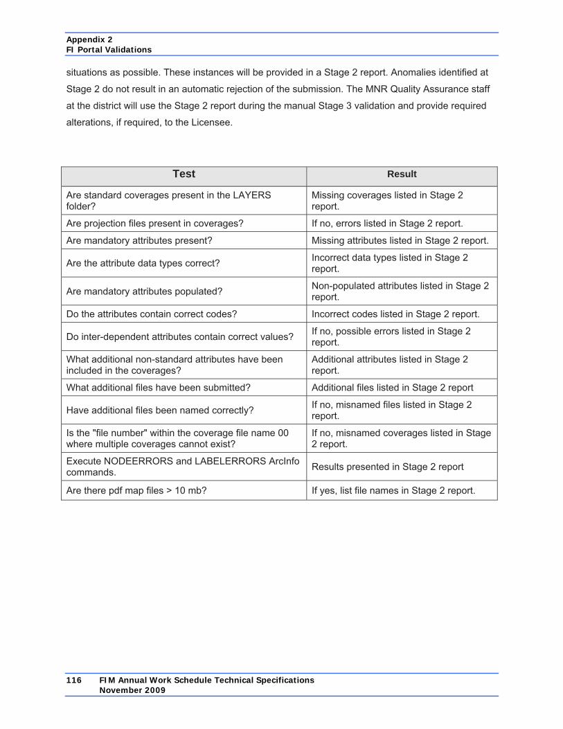
Appendix 2 FI Portal Validations
116 FIM Annual Work Schedule Technical Specifications November 2009
situations as possible. These instances will be provided in a Stage 2 report. Anomalies identified at
Stage 2 do not result in an automatic rejection of the submission. The MNR Quality Assurance staff
at the district will use the Stage 2 report during the manual Stage 3 validation and provide required
alterations, if required, to the Licensee.
Test Result
Are standard coverages present in the LAYERS folder?
Missing coverages listed in Stage 2 report.
Are projection files present in coverages? If no, errors listed in Stage 2 report.
Are mandatory attributes present? Missing attributes listed in Stage 2 report.
Are the attribute data types correct? Incorrect data types listed in Stage 2 report.
Are mandatory attributes populated? Non-populated attributes listed in Stage 2 report.
Do the attributes contain correct codes? Incorrect codes listed in Stage 2 report.
Do inter-dependent attributes contain correct values? If no, possible errors listed in Stage 2 report.
What additional non-standard attributes have been included in the coverages?
Additional attributes listed in Stage 2 report.
What additional files have been submitted? Additional files listed in Stage 2 report
Have additional files been named correctly? If no, misnamed files listed in Stage 2 report.
Is the "file number" within the coverage file name 00 where multiple coverages cannot exist?
If no, misnamed coverages listed in Stage 2 report.
Execute NODEERRORS and LABELERRORS ArcInfo commands. Results presented in Stage 2 report
Are there pdf map files > 10 mb? If yes, list file names in Stage 2 report.

Appendix 2 FI Portal Validations
FIM Annual Work Schedule Technical Specifications 117 November 2009
A2.4 Stage 2 Attribute Validations
The following tables identify the coverage attribute validations to be performed in Stage 2 Validation:
Scheduled Harvest Layer Attribute Mandatory
Attribute? Mandatory to be Populated?
Must Follow Correct Coding Scheme?
Coding Validation
AWS_YR Y C N • must be within plan period • at least one instance with submitted
AWS year SILVSYS Y C Y • mandatory where AWS_YR = fiscal
year HARVCAT Y C Y • BRIDGING only acceptable in 1st year
of FMP period • mandatory where AWS_YR = fiscal
year FUELWOOD Y C Y • mandatory where AWS_YR = fiscal
year Areas of Concern in Scheduled Operations Layer Attribute Mandatory
Attribute? Mandatory to be Populated?
Must Follow Correct Coding Scheme?
Coding Validation
AOCID Y Y N AOCTYPE Y Y Y Scheduled Residual Patches Layer l Attribute Mandatory
Attribute? Mandatory to be Populated?
Must Follow Correct Coding Scheme?
Coding Validation
AWS_YR Y C N • must be within plan period • at least one instance with submitted
AWS year RESID Y C N • mandatory where AWS_YR = fiscal
year

Appendix 2 FI Portal Validations
118 FIM Annual Work Schedule Technical Specifications November 2009
Scheduled Road Corridors Layer Attribute Mandatory
Attribute? Mandatory to be Populated?
Must Follow Correct Coding Scheme?
Coding Validation
AWS_YR Y C N • must be within plan period • at least one instance with submitted
AWS year ROADID Y C N • mandatory where AWS_YR = fiscal
year ROADCLAS Y C Y • mandatory where AWS_YR = fiscal
year AOCXID N N N NOXING N N N ACCESS N N C • mandatory where AWS_YR = fiscal
year DECOM N N C • mandatory where AWS_YR = fiscal
year CONTROL1 C C Y • ACCESS = Y CONTROL2 N N Y Scheduled Operational Road Boundaries Layer Attribute Mandatory
Attribute? Mandatory to be Populated?
Must Follow Correct Coding Scheme?
Coding Validation
AWS_YR Y C N • must be within plan period • at least one instance with submitted
AWS year ORBID Y C N • mandatory where AWS_YR = fiscal
year

Appendix 2 FI Portal Validations
FIM Annual Work Schedule Technical Specifications 119 November 2009
Scheduled Existing Road Activities Layer Attribute Mandatory
Attribute? Mandatory to be Populated?
Must Follow Correct Coding Scheme?
Coding Validation
AWS_YR Y C N • must be within plan period • at least one instance with submitted
AWS year ROADID Y C N • mandatory where AWS_YR = fiscal
year ROADCLAS Y C Y • mandatory where AWS_YR = fiscal
year ACCESS N* C* C • mandatory where AWS_YR = fiscal
year DECOM N* C* C • mandatory where AWS_YR = fiscal
year MAINTAIN N* C* C • mandatory where AWS_YR = fiscal
year MONITOR N* C* C • mandatory where AWS_YR = fiscal
year CONTROL1 C C Y • ACCESS = Y CONTROL2 N N Y *One of these four attributes is required to be yes on roads where AWS_YR = submitted AWS year. Scheduled Water Crossing Activities Layer Attribute Mandatory
Attribute? Mandatory to be Populated?
Must Follow Correct Coding Scheme?
Coding Validation
AWS_YR Y C N • must be within plan period plus 1 year • at least one instance with submitted
AWS year or following year WATXID Y Y N WATXTYPE Y Y Y CONSTRCT N C* C • mandatory where AWS_YR = fiscal
year or following year MONITOR N C* C • mandatory where AWS_YR = fiscal
year or following year REMOVE N C* C • mandatory where AWS_YR = fiscal
year or following year REPLACE N C* C • mandatory where AWS_YR = fiscal
year or following year ROADID Y C N • mandatory where AWS_YR = fiscal
year or following year *One of these four attributes is required to be yes when AWS_YR = submitted AWS year or following year.

Appendix 2 FI Portal Validations
120 FIM Annual Work Schedule Technical Specifications November 2009
Scheduled Non-Water AOC Crossings Layer Attribute Mandatory
Attribute? Mandatory to be Populated?
Must Follow Correct Coding Scheme?
Coding Validation
AWS_YR Y C N • must be within plan period • at least one instance with submitted
AWS year AOCXID Y C N • mandatory where AWS_YR = fiscal
year ROADID Y C N • mandatory where AWS_YR = fiscal
year Scheduled Aggregate Extraction Areas Layer Attribute Mandatory
Attribute? Mandatory to be Populated?
Must Follow Correct Coding Scheme?
Coding Validation
AWS_YR Y C N • must be within plan period • at least one instance with submitted
AWS year AGAREAID Y C N • mandatory where AWS_YR = fiscal
year Scheduled Site Preparation Treatments Layer Attribute Mandatory
Attribute? Mandatory to be Populated?
Must Follow Correct Coding Scheme?
Coding Validation
AWS_YR Y C N • must be within plan period • at least one instance with submitted
AWS year TRTMTHD1 Y C Y • mandatory where AWS_YR = fiscal
year TRTMTHD2+ N N Y

Appendix 2 FI Portal Validations
FIM Annual Work Schedule Technical Specifications 121 November 2009
Scheduled Regeneration Treatments Layer Attribute Mandatory
Attribute? Mandatory to be Populated?
Must Follow Correct Coding Scheme?
Coding Validation
AWS_YR Y C N • must be within plan period • at least one instance with submitted
AWS year TRTMTHD1 Y C Y • mandatory where AWS_YR = fiscal
year TRTMTHD2+ N N Y Scheduled Tending Treatments Layer Attribute Mandatory
Attribute? Mandatory to be Populated?
Must Follow Correct Coding Scheme?
Coding Validation
AWS_YR Y C N must be within plan period at least one instance with submitted AWS year
TRTMTHD1 Y C Y • mandatory where AWS_YR = fiscal year
TRTMTHD2+ N N Y Scheduled Protection Treatments Layer Attribute Mandatory
Attribute? Mandatory to be Populated?
Must Follow Correct Coding Scheme?
Coding Validation
AWS_YR Y C N • must be within plan period • at least one instance with submitted
AWS year TRTMTHD1 Y C Y • mandatory where AWS_YR = fiscal
year TRTMTHD2+ N N Y

Appendix 2 FI Portal Validations
122 FIM Annual Work Schedule Technical Specifications November 2009
Forestry Aggregate Pits Layer Attribute Mandatory
Attribute? Mandatory to be Populated?
Must Follow Correct Coding Scheme?
Coding Validation
PIT_ID Y Y N PIT_OPEN Y Y N • YYYYMMMDD PITCLOSE Y C* N • cannot be > PIT_OPEN + 10
• YYYYMMMDD CAT9APP Y C* N • cannot be > PIT_OPEN + 10
• YYYYMMMDD * One of these two attributes must be populated.

Appendix 3 Data Identification Form
FIM Annual Work Schedule Technical Specifications 123 November 2009
Appendix 3 Data Identification Form Contact Information First Name /Last Name Telephone Number
Licensee Name Address
Data Details
Data Type Description Location Source
Change Type
Observation Date
Location Description
Geographic Coordinate System Comments
Datum
Data Accuracy >>> Select one from the list
Within 1 metre Within 50 metres Within 2 metres Within 100 metres Within 5 metres Within 200 metres
Within 10 metres Within 500 metres Within 20 metres Within 1,000 metres

Appendix 3 Data Identification Form
124 FIM Annual Work Schedule Technical Specifications November 2009
Data Identification Form Instructions
This form may be used by the Licensee when providing updated values information. If the updated
value(s) results in changes to operations, this form will accompany the changes to values
documentation and may reference the map, if applicable, included in the documentation. This
document will not be available to the public on the MNR website.
Contact Information
• First Name/Last Name: The Licensee representative that is familiar with the information
contained in the form.
• Telephone Number: The telephone number where the Licensee representative can be
reached.
• Licensee Name: The company name of the Licensee.
• Address: The mailing address of the Licensee.
Data Details
• Data Type Description: Provide a description of the natural resource feature or value type that
has been identified. The description need only be detailed enough to relate to a
specific AOC prescription in the FMP (e.g., osprey nest, cool water stream).
• Change Type: Enter one of the following change types for the information being provided:
- new value
- value no longer exists
- location correction
- data type (e.g., osprey nest to hawk nest)
• Observation Date: Provide the date the new or changed information was observed. The format
is dd/mmm/yyyy. The month is recorded as text. For example: 05/JUN/2007
• Location Source: Provide a general description of the source (methodology) for the location
information being provided. For example: estimated in relation to base features, or
GPS, or ortho-rectified imagery. Not required if the natural resource feature or value
is being identified as no longer exists or as a change in type.

Appendix 3 Data Identification Form
FIM Annual Work Schedule Technical Specifications 125 November 2009
• Location Description: As a minimum, provide a textual description of the location of the natural
resource feature or value in relation to existing base features or values. Other
acceptable location descriptions could be geographic coordinates, a reference to an
attached photo or map (this could be the same map, or a map meeting the same
standards, as required for changes to operations documentation, as per the FIM
Annual Work Schedule Technical Specifications) or reference to an accompanying
digital spatial data product. This information is required for all changes.
• Geographic Coordinate System: If coordinates have been provided in the Location
Description section of the form, identify the geographic coordinate system (e.g.,
lat/long, UTM/Zone). If a digital spatial data product has been provided, this
information will be contained in the associated projection file.
• Datum: If coordinates have been provided in the Location Description section of the form,
identify the projection datum (e.g., NAD83). If a digital spatial data product has been
provided, this information will be contained in the associated projection file.
• Comments: Provide any additional comments that may be relevant to the natural resource
feature or value that has been identified.
• Data Accuracy: Indicate the general accuracy of the location information being provided by
selecting/marking one of the categories listed on the form.