filtration station operating manual
TRANSCRIPT
®
Filtration Station Operating Manual

1. Warnings / Cautions & Notes .......................................................................................................…………..4 1.1 Acronym List………………………................................................................................…………. … 5
2. Specifications..............................................................................................................................................6
3. Controls and Indicators..................................................................................................................………....7
4. General Operations......................................................................................................................………… 11
5. Cleaning Methods & Times...........................................................................................................…………12 5.1 Filtration Technique…………………...............................................................................……….....12 5.2 Manual / Auto Mode Selector Switch..............................................................................………….13 5.3 Start-Up…………………..………….................................................................................………….13
6. Maintenance.................................................................................................................................…………14 6.1 ServicingFilterElements…………...........................................................................................…..14 6.2 ServicingtheStrainer…..…………................................................................................…………..15 6.3 DCMotor……………………………................................................................................…………..15
7. CS1000Operation.........................................................................................................................………...16 8. CS1000 Modes & Menus....................................................................................................................…......19 8.1 Power Up Menu.....…………………...............................................................................……….....20 8.2 Measuring Menu............................................................................................................…………. 20
9. CS1000TechnicalData.....................................................................................................................…..…22
10. Fluid Monitoring Software (FluMoS).....................................................................................………............23 10.1 System Requirements………............................................................................................……......23 10.2 AdapterBox–DriverInstructions....................................................................................…………23 10.3 Installing FluMoS……...………..................................................................................………… ......25 10.4 Uninstall FluMoS…. ……...………............................................................................................. ....28 10.5 Starting FluMoS.....………..............................................................................................………….28 10.6 ScanningforUnits.....……….…...………................................................................................…....28 10.7 Serial Interfaces........……….…...………................................................................................…....29 10.8 ProcessingMeasurementData.....……….…...………...................................................................30 10.9 ExportingMeasurementData...………................................................................................….......31 10.10 Measurement File Format..……….................................................................................................32 10.11 SaveResults..…....................…….................................................................................................33
11. Aqua Sensor (AS1000)....................................................................................................................…...….33 11.1 AS1000TechnicalData...................................................................................................…………35
12. Maintenance Procedure................................................................................................................………...37
Appendix A : Troubleshooting….....……………......................................................................................................39Appendix B : Troubleshooting CS1000 …………………………..…........................................................................41Appendix C1:ISO4406.........………….................................................................................................…………..43Appendix C2:SAEAS4059....……………............................................................................................…………..44Appendix C3:NAS1638..……………….................................................................................................………….45
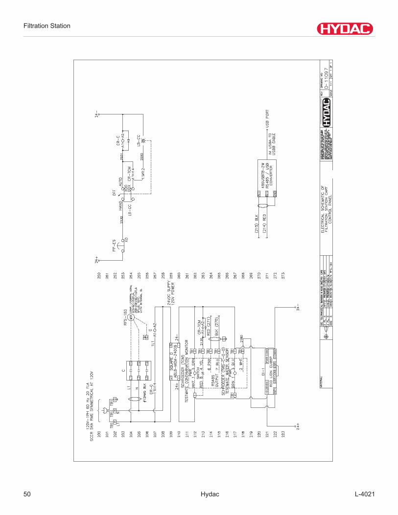
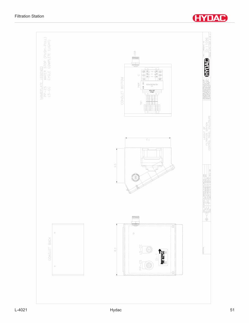
SalesDrawing……………………….………………........................................................................……….........…....46PartsListDrawing………………….………………..............................................................................……...…….....47HydraulicSchematicDrawing...…….……………….................................................................................…………..48ElectricalSchematic,ControlPanel.........................................................................................................................49Control Panel Schematic......................…………….………………...........................................................................50Control Panel Layout...............................................................................................................................................51ElectricalSchematic,ControlPanel.........................................................................................................................52
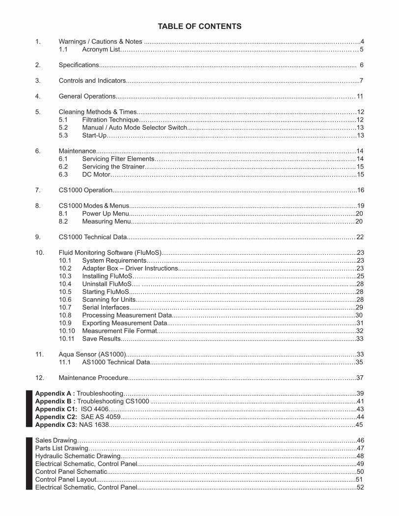
TABLE OF CONTENTS
Filtration Station
Hydac L-40214
1. WARNINGS, CAUTIONS AND NOTES Recognize Safety Information This is the safety alert symbol. When you see this symbolonyourmachineorinthismanual,bealertfor the potential of personal injury. Follow the precautions and safe operating practices highlighted by this symbol. A signal word — DANGER,WARNING,orCAUTION — usedwiththesafetyalertsymbol.DANGERidentifiesthemostserioushazards.GeneralprecautionsareonCAUTION labels.
Follow Safety Instructions Read the safety messages in this manual and on the machine. Follow these warnings and instructions carefully. Reviewthemfrequently.Besurealloperatorsofthismachineunderstandeverysafetymessage.Replacesafetylabels immediately if missing or damaged.
OperateOnlyIfQualifiedDonotoperatethismachineunlessyouhavereadtheoperator’smanualcarefullyandyouhavebeenqualifiedbysupervisedtrainingandinstruction.Familiarizeyourselfwiththejobsiteandyoursurroundingsbeforeoperating.
Inspect Machine Inspect the equipment carefully before each use. Keep all parts in good condition and properly installed. Fix damage and replace worn or broken parts immediately. Pay special attention to hydraulic hoses and electrical power cord.
HandleFluidsSafely—AvoidFiresFilteringoffuelorotherflammableliquidsisnotrecommended.Storeflammablefluidsawayfromfirehazards.Donotincinerateorpuncturepressurizedcontainers.Makesuremachineiscleanoftrash,grease,anddebris.Donot store oily rags; they can ignite and burn spontaneously.
PrepareforEmergenciesBepreparedifafirestarts.Keepafirstaidkitandfireextinguisherhandy.Keepemergencynumbersfordoctors,ambulanceservice,hospital,andfiredepartmentnearyourtelephone.
Practice Safe Maintenance Understandserviceprocedurebeforedoingwork.Workareashouldlevel,clean,anddry.Beforeservicingmachine: -Positionmachineonalevelsurface - Allow to cool if hot
Keep all parts in good condition and properly installed. Fix damage immediately. Replace worn or broken parts. Removeanybuildupofgrease,oil,ordebris.
Handle Chemical Products Safely Directexposuretohazardouschemicalscancauseseriousinjury.Potentiallyhazardouschemicalsusedincludesuchitemsaslubricants,coolants,paints,andadhesives.AMaterialSafetyDataSheet(MSDS)providesspecificdetailsonchemicalproducts:physicalandhealthhazards,safetyprocedures,andemergencyresponsetechniques.ChecktheMSDSbeforeyoustartanyjobusingahazardouschemical.Thatwayyouwillknowexactlywhattherisksareandhowtodothejobsafely.Thenfollowprocedures and recommended equipment.
!

Filtration Station
L-4021 Hydac 5
WearProtectiveClothingWearclosefittingclothingandsafetyequipmentappropriatetothejob.Operatingequipmentsafelyrequiresthefullattentionoftheoperator.Donotwearradioormusicheadphoneswhileoperatingthemachine.
ServiceMachinesSafelyTielonghairbehindyourhead.Donotwearanecktie,scarf,looseclothing,ornecklacewhenyouworknearmachinetoolsormovingparts.Iftheseitemsweretogetcaught,severeinjurycouldresult.Removeringsandotherjewelrytopreventelectricalshortsandentanglementinmovingparts.
Illuminate Work Area Safely Illuminate your work area adequately but safely. Use a portable safety light for working inside or under the machine.Makesurethebulbisenclosedbyawirecage.Thehotfilamentofanaccidentallybrokenbulbcanignite spilled fuel or oil.
Work In Clean Area Beforestartingajob: - Clean work area and machine -Makesureyouhaveallnecessarytoolstodoyourjob. -Havetherightpartsonhand. - Read all instructions thoroughly; do not attempt shortcuts.
Use Proper Tools Usetoolsappropriatetothework.Makeshifttoolsandprocedurescancreatesafetyhazards.Forlooseningandtighteninghardware,usethecorrectsizetools.DONOTuseU.S.measurementtoolsonmetricfasteners.Avoidbodilyinjurycausedbyslippingwrenches.Useonlyservicepartsmeetingspecifications.
DisposeofWasteProperlyImproperlydisposingofwastecanthreatentheenvironmentandecology.Potentiallyharmfulwasteincludesuchitemsasoil,fuel,coolant,brakefluid,filters,andbatteries.Useleak-proofcontainerswhendrainingfluids.Donotusefoodorbeveragecontainersthatmaymisleadsomeoneintodrinkingfromthem.Donotpourwasteontotheground,downadrain,orintoanywatersource.
1.1 ACRONYM LIST
CS1000 Contamination SensorAS1000 Aqua Sensor
DHC DirtHoldingCapacityGPM Gallons Per MinuteVFD VariableFrequencyDriveVAC Voltage Alternating CurrentVDC VoltageDirectCurrentPOT PotentiometerNPT National Pipe ThreadORB O-Ring Boss
Filtration Station
Hydac L-40216
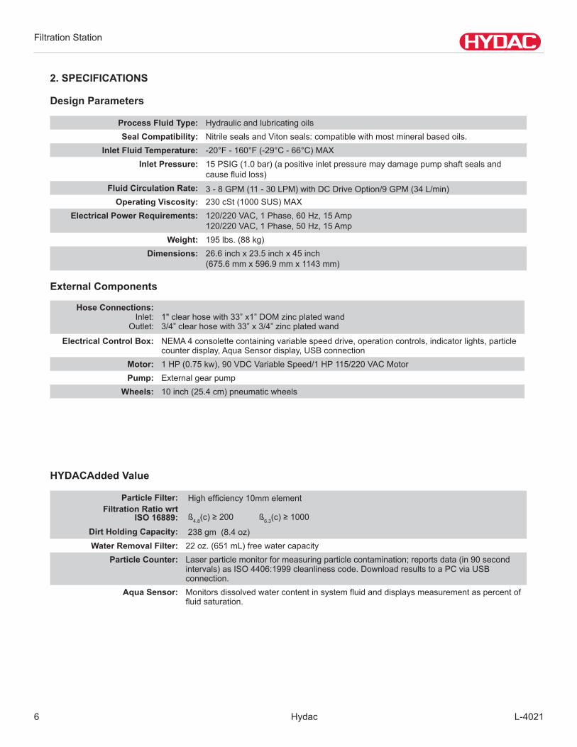
Process Fluid Type: Hydraulic and lubricating oils Seal Compatibility: NitrilesealsandVitonseals:compatiblewithmostmineralbasedoils.
Inlet Fluid Temperature: -20°F-160°F(-29°C-66°C)MAXInlet Pressure: 15PSIG(1.0bar)(apositiveinletpressuremaydamagepumpshaftsealsand
causefluidloss)Fluid Circulation Rate: 3-8GPM(11-30LPM)withDCDriveOption/9GPM(34L/min)
Operating Viscosity: 230cSt(1000SUS)MAXElectrical Power Requirements: 120/220VAC,1Phase,60Hz,15Amp
120/220VAC,1Phase,50Hz,15AmpWeight: 195 lbs. (88 kg)
Dimensions: 26.6inchx23.5inchx45inch(675.6mmx596.9mmx1143mm)
Design Parameters
Hose Connections:Inlet:
Outlet:1"clearhosewith33”x1”DOMzincplatedwand3/4”clearhosewith33”x3/4”zincplatedwand
Electrical Control Box: NEMA4consolettecontainingvariablespeeddrive,operationcontrols,indicatorlights,particlecounterdisplay,AquaSensordisplay,USBconnection
Motor: 1HP(0.75kw),90VDCVariableSpeed/1HP115/220VACMotorPump: Externalgearpump
Wheels: 10 inch (25.4 cm) pneumatic wheels
Particle Filter:Filtration Ratio wrt
ISO 16889:Dirt Holding Capacity:
Highefficiency10mm element ß4.8(c)≥200 ß6.3(c)≥1000 238gm(8.4oz)
Water Removal Filter: 22oz.(651mL)freewatercapacityParticle Counter: Laser particle monitor for measuring particle contamination; reports data (in 90 second
intervals)asISO4406:1999cleanlinesscode.DownloadresultstoaPCviaUSBconnection.
Aqua Sensor: Monitorsdissolvedwatercontentinsystemfluidanddisplaysmeasurementaspercentoffluidsaturation.
External Components
HYDACAdded Value
2. SPECIFICATIONS
Filtration Station
L-4021 Hydac 7
3. CONTROLS AND INDICATORSControl/Indicator Description
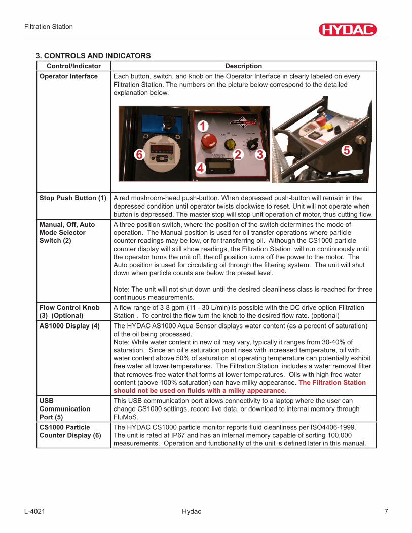
Operator Interface Eachbutton,switch,andknobontheOperatorInterfaceinclearlylabeledoneveryFiltration Station. The numbers on the picture below correspond to the detailed explanation below.
Stop Push Button (1) A red mushroom-head push-button. When depressed push-button will remain in the
depressed condition until operator twists clockwise to reset. Unit will not operate when buttonisdepressed.Themasterstopwillstopunitoperationofmotor,thuscuttingflow.
Manual, Off, Auto Mode Selector Switch (2)
Athreepositionswitch,wherethepositionoftheswitchdeterminesthemodeofoperation. The Manual position is used for oil transfer operations where particle counterreadingsmaybelow,orfortransferringoil.AlthoughtheCS1000particlecounterdisplaywillstillshowreadings,theFiltrationStationwillruncontinuouslyuntilthe operator turns the unit off; the off position turns off the power to the motor. The Autopositionisusedforcirculatingoilthroughthefilteringsystem.Theunitwillshutdownwhenparticlecountsarebelowthepresetlevel.
Note:Theunitwillnotshutdownuntilthedesiredcleanlinessclassisreachedforthreecontinuous measurements.
Flow Control Knob (3) (Optional)
Aflowrangeof3-8gpm(11-30L/min)ispossiblewiththeDCdriveoptionFiltrationStation.Tocontroltheflowturntheknobtothedesiredflowrate.(optional)
AS1000 Display (4) TheHYDACAS1000AquaSensordisplayswatercontent(asapercentofsaturation)of the oil being processed.Note:Whilewatercontentinnewoilmayvary,typicallyitrangesfrom30-40%ofsaturation.Sinceanoil’ssaturationpointriseswithincreasedtemperature,oilwithwatercontentabove50%ofsaturationatoperatingtemperaturecanpotentiallyexhibitfreewateratlowertemperatures.TheFiltrationStationincludesawaterremovalfilterthatremovesfreewaterthatformsatlowertemperatures.Oilswithhighfreewatercontent(above100%saturation)canhavemilkyappearance.The Filtration Station should not be used on fluids with a milky appearance.
USB Communication Port (5)
ThisUSBcommunicationportallowsconnectivitytoalaptopwheretheusercanchangeCS1000settings,recordlivedata,ordownloadtointernalmemorythroughFluMoS.
CS1000 Particle Counter Display (6)
TheHYDACCS1000particlemonitorreportsfluidcleanlinessperISO4406-1999.TheunitisratedatIP67andhasaninternalmemorycapableofsorting100,000measurements.Operationandfunctionalityoftheunitisdefinedlaterinthismanual.
64
1
2 3 5

Filtration Station
Hydac L-40218
Particulate Filter Indicator
TheHYDACvisualindicatorwillextendwhenbypassdifferentialpressureisreached.Whenextended,theindicatorwillbeRED.Note:Runningtheunitatlowerflowswillallowforlongerfilterlife.Changefilterbyfollowing the procedure outlined in the Maintenance Section.
Air Bleed off Valve/Fluid Sampling Port
Thisairbleedoffvalveisusedtoremoveanyairtrappedinthefilterhousingafteran element drainage or when air was accidentally sucked into the Filtration Station throughthesuctionwand.Thisvalvecanalsobeusedtosamplefluidbeingfiltered.
AS1000 Sensor
ThissenorismountedinthebaseofthefilterhousingandmeasuresthepercentofsaturationofthefluidbeingrunthroughtheFiltrationStation.Thissensortakesmeasurementsbeforethefluidreachestheelement.

Filtration Station
L-4021 Hydac 9
Lift Bar
Theliftbaristhedesignatedpickpointforacraneoranyotherliftingdevice.ThiswillallowtheFiltrationStationtobeliftedverticallyatthecenterofgravity.
Element Storage Containers
There is an element storage area on the back of the cart. These containers should be used to store new and used elements.
Filtration Station
Hydac L-402110
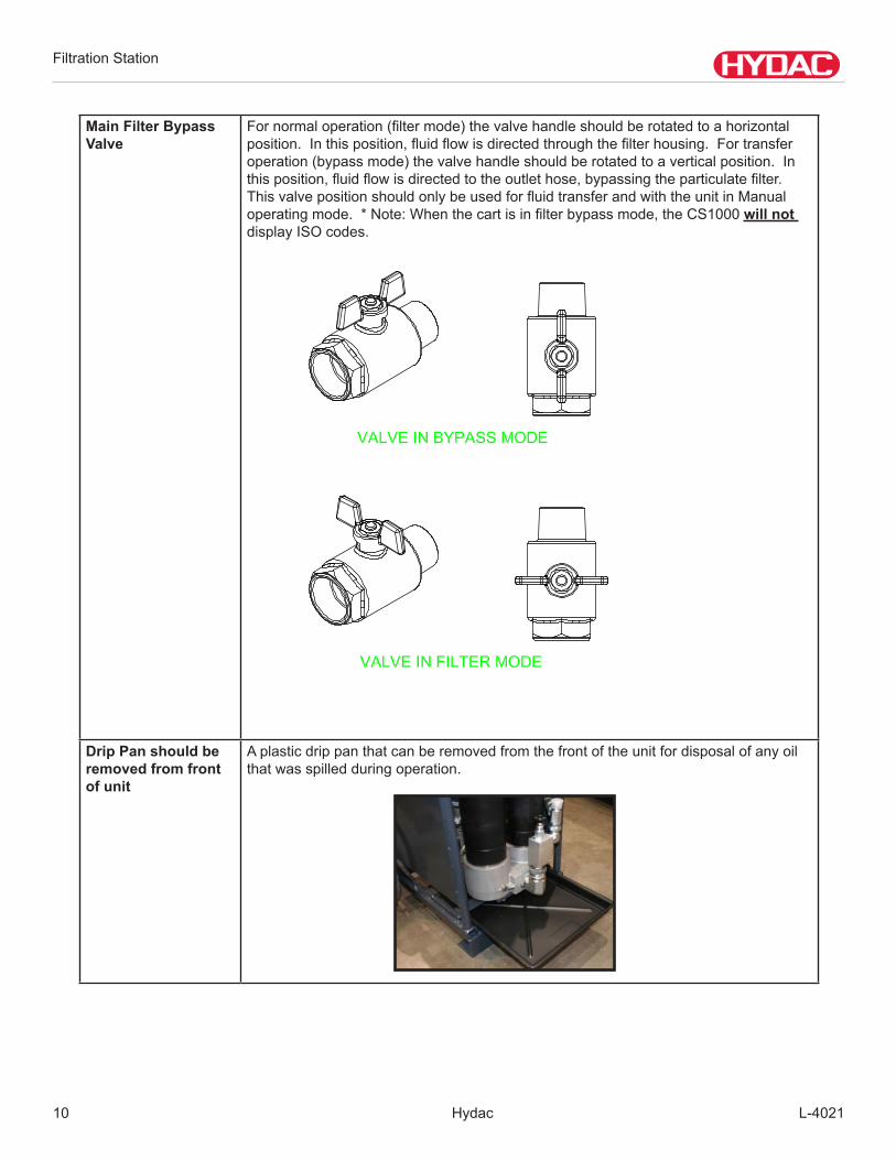
Main Filter Bypass Valve
Fornormaloperation(filtermode)thevalvehandleshouldberotatedtoahorizontalposition.Inthisposition,fluidflowisdirectedthroughthefilterhousing.Fortransferoperation(bypassmode)thevalvehandleshouldberotatedtoaverticalposition.Inthisposition,fluidflowisdirectedtotheoutlethose,bypassingtheparticulatefilter.ThisvalvepositionshouldonlybeusedforfluidtransferandwiththeunitinManualoperatingmode.*Note:Whenthecartisinfilterbypassmode,theCS1000will not display ISO codes.
Drip Pan should be removed from front of unit
Aplasticdrippanthatcanberemovedfromthefrontoftheunitfordisposalofanyoilthat was spilled during operation.

Filtration Station
L-4021 Hydac 11
4. GENERAL OPERATIONS
TheFiltrationStationisdesignedtoremoveparticulateandfreewatercontamination,aswellasmonitortheoilcontaminantlevelsinfluidpoweredsystems.FluidcontaminationisdisplayedasanISO4406CleanlinessCodeusingalightblockingtechnology.Dissolvedwatercontentoftheoilisdisplayedaspercentofsaturation.TheFiltrationStationisanoilfilteringsystemthatcapturescontaminantparticlesusinghighperformancefiltersoracombinationofwaterandparticulateremovalelements.
BelowaresummarizedinstructionsforoperatingtheFiltrationStation.
•Allsafetyproceduresassociatedwiththeoperationofelectricalpoweredequipmentmustbeobserved.
•Placethesuction(1”)hoseintothefluidtobefilteredortransferred.Placethedischarge(3/4”)hoseintothemachineryreservoirorwastecontainerdependingondesiredoperation.Ensurethatthewandsaresecuredtoavoidpossiblefluidloss.
• ELECTRICAL WARNING •Thesystem’s1½HPelectricmotordraws15ampsat115volts±10%,60Hzatfullload.Starting
current could be approximately 4 to 8 times greater. A proper circuit breaker should be installed to protectthemotorandmeetnationalandlocalelectriccodes.Recommendedsizeforanextension cable is 12AWG - 3 conductor with a maximum length of 25 feet.
•Themotorisdesignedforoperationonthevoltageandfrequencysuppliedonthemotornameplate
•Normalloadswillbehandledsafelyonvoltagesnotmorethan10%aboveorbelowthe specifiedvoltages
•Runningunitonvoltagesnotwithinrangemaycauseoverheatingandmotorburnout
•Heavyloadsrequirethevoltageatmotorterminalsbenotlessthanthevoltagespecified
•Tostarttheunit,placethemodeselectorswitchinthecorrectposition(ManualorAuto)forthedesiredoperation.Settingthespeedcontrolatabout3gpm(11L/min)isrecommendedforstartupiftheDCdriveoption is equipped.
Donotatanytimeallowpumptorundry.Allowingthepumptorunwithoutfluidflowingthroughitwillgreatlyreducepumplife.Duringfluidtransferoperationitiscriticalthatthepumpinletstaysubmergedinfluid.Pumpsthatareallowedtorundrywillnotbecoveredbywarranty.
Filtration Station
Hydac L-402112
5. CLEANING METHODS & TIMES
ThefollowingtableshavebeendevelopedtohelpdealersestimatethecleaningtimeswiththeFiltrationStation.NewtestingwiththeFiltrationStationhasallowedthedevelopmentoftheupdatedcleaningtimetables.Somefigureswereobtainedbyextrapolation.
Cleaningtimecanbeaffectedbysomefactors.KeepinmindthattheFiltrationStationisalwayscleaningthefluidsevenifthereadingsontheparticlecounterdon’tshowit.Thereasonsforthisfalsereadinginclude:
• The Filtration Station is producing air•TheFiltrationStationiscavitating• The particle counter has air bubbles trapped in sensing line•Thereturnwandisnotsubmergedinfluid•Thefiltertowerhasnotbeenpurged•MorethanoneFiltrationStationisbeingusedsimultaneouslyproducingtoomuchfluidturbulenceinreservoir• The oil is too cold•Theoilisheavilycontaminatedwithwaterandparticles• The speed is set too slow
Cleaningtimescanvary,butshouldrarelytakemorethanonehouronmediumsizeconstructionmachinesthatarenotextremelydirty.Reachinghighcleanlinesslevelsonproductionsizemachines,,couldtakelongerthanonehour.
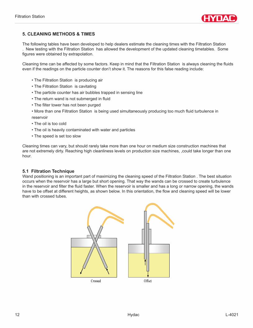
5.1 Filtration TechniqueWandpositioningisanimportantpartofmaximizingthecleaningspeedoftheFiltrationStation.Thebestsituationoccurswhenthereservoirhasalargebutshortopening.Thatwaythewandscanbecrossedtocreateturbulenceinthereservoirandfilterthefluidfaster.Whenthereservoirissmallerandhasalongornarrowopening,thewandshavetobeoffsetatdifferentheights,asshownbelow.Inthisorientation,theflowandcleaningspeedwillbelowerthan with crossed tubes.

Filtration Station
L-4021 Hydac 13
Whenchangingbetweenreservoirscontainingdifferentfluids,thefollowingprocedureshouldbefollowed:
•Prepareanemptywasteoilcontainer(5gallonbucket),aswellasatop-offcontainerforfluidremovedfromthe hydraulic system (5 gallons).
•Insertsuctionwandintoreservoirandplacedischargewandintothewastecontainer.•Replaceexistingparticlefilterandwaterremovalfilterwiththoseofthefluidinthemachine•RuntheFiltrationStationuntilthewastecontainerisfilledwithabout4gallonsoffluid.•Removedischargewandfromwastecontainer,wipeitclean,andinsertintoreservoir.•Positionwandsinthecorrectorientationandbeginreservoirfiltrationuntildesiredcleanlinesslevelhasbeenachieved.
• Cycle machine hydraulic functions.•Resumereservoirfiltration.
5.2 Manual /Auto Mode Selector Switch ManualPositionisusedforfluidtransfer.TheManualpositionavoidsparticlecountershutdownduetocleanfluid.OperationoftheFiltrationStationwiththeswitchintheManualpositionwouldtypicallybeusedtotransferwastefluidsoutofmachinerytoawastecontainerfordisposalortotransfernewfluidtomachinery.Filtrationisnotnormallyrequiredforwastetransfer.Totransferwithoutfiltration,theMainFilterBypassvalve(yellowhandle)shouldbesetinthehorizontalposition.Inthisposition,fluidisdiverteddirectlyfromthepumpoutletthedischargehose.TheManualpositionmayalsobeusedwhentransferringnewfluidintomachinery,inwhichcase,filtrationisrecommended.ThisisaccomplishedbysettingtheMainFilterBypassvalvetotheverticalposition.
AutoPositionisusedforkidneyloopfiltrationofequipmentreservoirs.InAutoModetheparticlecounterwillshutdowntheFiltrationStationwhenfluidcleanlinessmeetsspecifiedlevels.TheMainFilterBypassvalvemustbeintheverticalpositiontodirectflowthroughtheparticulatefilterhousingandparticlecountertransducer.IftransferingwatersaturatedfluidthroughtheFiltrationStation,theelementcanbechangedtothewaterremovalelementwiththevalveinthehorizontalposition.
For procedure on changing Auto Mode cleanliness levels please see section 8.2.
5.3 Start-Up Afterabovesetupiscomplete,theunitisnowreadyforstartup.Placetheselectorswitchtoeithermanualorautomatic,andadjustthebypassvalve.Flowratecanbeadjustedbyrotatingthemotor-speedcontrolknobonoperatorconsole,clockwiserotationtoincreaseflow.Theparticlecounterinputisdeactivatedforthefirstfiveminutesfollowingthestart-upoftheFiltrationStationtoallowtheparticlecountertoflushoutpreviouslyrunfluid.InAutoMode,theFiltrationStationwillshutdownautomaticallyoncethepresetparticlecountisachieved.Theyellow selector switch (system clean) indicator light will remain illuminated after shut down to indicate that system is clean. Formanualshutdownatanytime,depresstheEmergencyMasterStopbutton.ResettheStopbuttonbytwistingclockwise.Donotallowpumptorundry.

Filtration Station
Hydac L-402114
6. MAINTENANCE Nomaintenanceoperationsotherthanadjustmentoftheflowshouldbecarriedoutwhiletheunitisrunning.Be-forestartinganyothermaintenanceoperations,ensurethatthesystemisshutdownandelectricallysafe.Systempressurecanbecontainedintheunitforsometimeafterithasbeendisconnected.Torelieveexcesspressureopenthebypassvalve.Thisiswillreturnsystempressuretoatmosphere.
6.1 Servicing Filter Elements
Priortoservicingthefilter,bleedoffanytrappedpressureintheFiltrationStation.Depressthetopoffthebleedpluguntilallpressureisrelieved.Excessfluidwillbedispensedintothedrippan.
Turnthefiltercapcounterclockwiseusinga1½”wrench or socket until the threads are no longer engaged.Removethecapandinspecto-ringincapfor damage. Replace if required. Next,removetheusedelementandreplacewithanewelement. Additional element and storage is located in the back of the Filtration Station .
Withnewelementinstalled,insertcapbushingintotopof element. Tighten the cap clockwise until all of the threads are engaged.
Uponstart-up,thefilterhousingwillneedtobebledofanytrappedairtoensurealloftheelementisutilizedformaximumefficiency.Depressthebleedvalveuntilfluidstartstocomeoutofthebleedhose.
Filtration Station
L-4021 Hydac 15
Do not run the system without a filter element installed. Use only specified replacement filter elements.
6.2 Servicing the Strainers
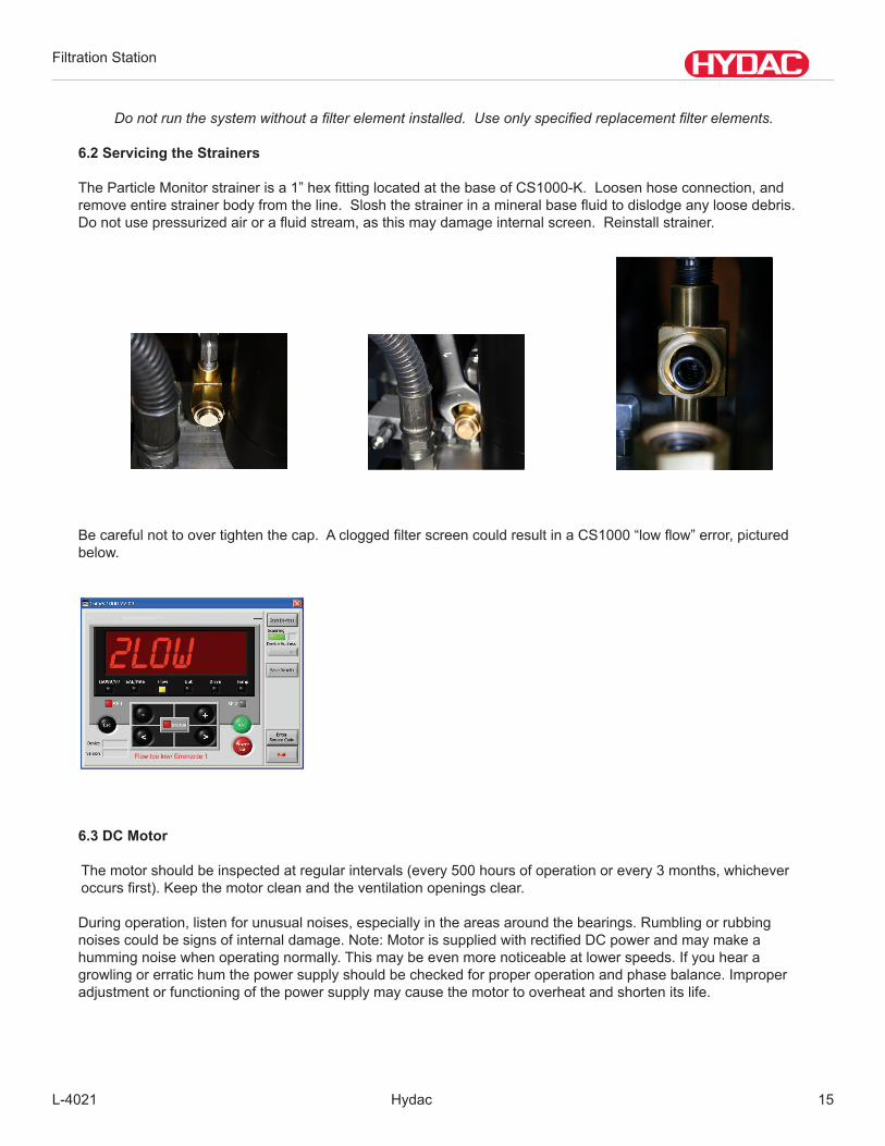
TheParticleMonitorstrainerisa1”hexfittinglocatedatthebaseofCS1000-K.Loosenhoseconnection,andremoveentirestrainerbodyfromtheline.Sloshthestrainerinamineralbasefluidtodislodgeanyloosedebris.Donotusepressurizedairorafluidstream,asthismaydamageinternalscreen.Reinstallstrainer.
Becarefulnottoovertightenthecap.AcloggedfilterscreencouldresultinaCS1000“lowflow”error,picturedbelow.
6.3 DC Motor
Themotorshouldbeinspectedatregularintervals(every500hoursofoperationorevery3months,whicheveroccursfirst).Keepthemotorcleanandtheventilationopeningsclear.
Duringoperation,listenforunusualnoises,especiallyintheareasaroundthebearings.Rumblingorrubbingnoisescouldbesignsofinternaldamage.Note:MotorissuppliedwithrectifiedDCpowerandmaymakeahummingnoisewhenoperatingnormally.Thismaybeevenmorenoticeableatlowerspeeds.Ifyouhearagrowling or erratic hum the power supply should be checked for proper operation and phase balance. Improperadjustmentorfunctioningofthepowersupplymaycausethemotortooverheatandshortenitslife.

Filtration Station
Hydac L-402116
7. CS1000 OPERATION
DisplayandKeypadElements(CS1000-D)
Thekeypadconsistsofsixkeys.ThesekeysareusedtooperatetheCS1000andtonavigatethroughthemenus(hierarchically structured).
Measured variablesThemeasurementvariablesprovidetheuserinformationaboutthecleanliness(orcontamination)oftheoilinhisfacility.Themeasurementvariablesarecalibrated.Theyindicateameasuredvaluewithanaccuracyof+/--0.5codes/class.
Measuredvariable“ISO”
Measuredvariable“SAE”
Servicevariables
TheservicevariablesenabletheusertoretrieveinformationonthecurrentstatusintheContaminationMonitor.Theservicevariablesarenotcalibrated.Theyindicateanapproximatevalue.
Pos. LED DescriptionA Status Indicates the status of the Contamination SensorB Display Consistsofsixdigitsandshowsthemeasuredvalues.C Measured Variable Indicatesthemeasuredvariableofthedisplayvalue,i.e.
ISO/SAE/NAS
D Additional Variable Indicatesthemeasuredvariableofthedisplayvalue,i.e.Flow/Out/Drive/Temp
E Switch point 1 Indicatesthestatusoftheswitchingout.Whenlit,theswitchingoutputisactivated(closed).
F Switch point 2 Reservedforfutureuse
Filtration Station
L-4021 Hydac 17
Servicevariables“Flow”
Servicevariables“Out”
Servicevariables“Drive”
Servicevariables“Temp”
Key LockThekeypadcanbelockedtoprevententriesfrombeingmade.Toactivateordeactivatekeypadlocking,pressbothkeyssimultaneously:The display switches to the preset display after 1 second.
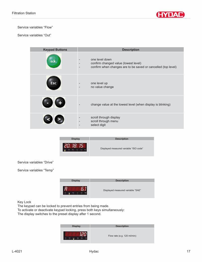
Keypad Buttons Description
- oneleveldown- confirmchangedvalue(lowestlevel)- confirmwhenchangesaretobesavedorcancelled(toplevel)
- onelevelup- novaluechange
- changevalueatthelowestlevel(whendisplayisblinking)
- scroll through display- scroll through menu- select digit
Display Description
Displayedmeasuredvariable“ISOcode”
Display Description
Displayedmeasuredvariable“SAE”
Display Description
Flow rate (e.g. 120 ml/min)

Filtration Station
Hydac L-402118
Display Description
Showscurrentorvoltagelevelattheanalogoutput.(example:13.8mA)
Display Description
Showstheefficiency(1-100%)withwhichtheLEDcurrentlyworksintheCS1000.(example:60%)
Display Description
Shows the temperature in the sensor. (example:29.5°Cor84.2°F)
NOTE:Thefluidtemperatureisnotdisplayed,onlythetemperature inside of the CS1000 housing is displayed.
Actuate these keys The following appears in the display (1 sec)
Description
KeyLockisactivated
KeyLockisdeactivated
Filtration Station
L-4021 Hydac 19
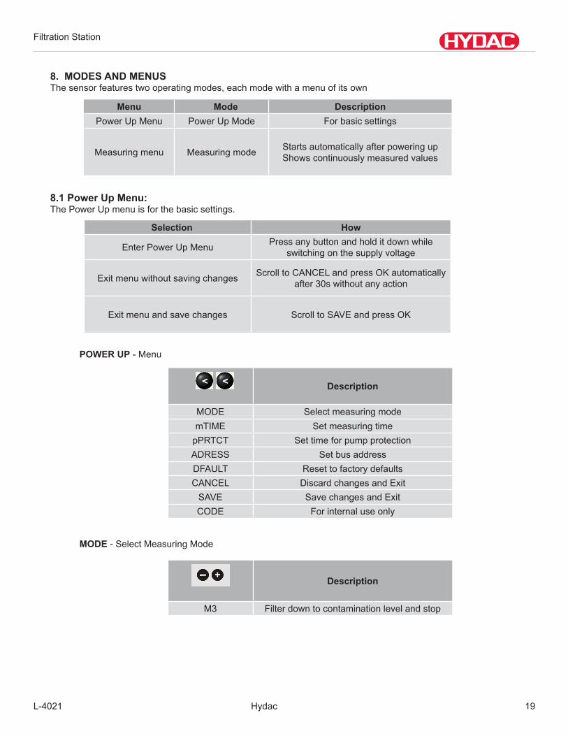
8. MODES AND MENUSThesensorfeaturestwooperatingmodes,eachmodewithamenuofitsown
8.1 Power Up Menu:The Power Up menu is for the basic settings.
POWER UP - Menu
MODE - Select Measuring Mode
Menu Mode DescriptionPower Up Menu Power Up Mode For basic settings
Measuring menu Measuring mode Starts automatically after powering upShowscontinuouslymeasuredvalues
Selection How
EnterPowerUpMenu Press any button and hold it down while switchingonthesupplyvoltage
Exitmenuwithoutsavingchanges ScrolltoCANCELandpressOKautomaticallyafter 30s without any action
Exitmenuandsavechanges ScrolltoSAVEandpressOK
Description
MODE Select measuring modemTIME Set measuring time
pPRTCT Set time for pump protectionADRESS Set bus addressDFAULT Reset to factory defaultsCANCEL DiscardchangesandExitSAVE SavechangesandExitCODE For internal use only
Description
M3 Filterdowntocontaminationlevelandstop

Filtration Station
Hydac L-402120
mTIME - Set Measuring Time
pPRTCT - Set Time for Pump Protection
ADRESS - Set Bus Address
DFAULT - Reset to factory defaults
CANCEL-Discardchangesandexit
SAVE-Savechangesandexit
CODE-Activateservicemenu-For internal use only
8.2 Measuring Menu:The Measuring Menu allows the changing of setting during operation.
Description
60 Set time in seconds (10 - 300)
Description
0 Settimeforstopwithnoflowin“seconds”(0-10)
Description
HECOM z Setaddress(a,b,...z)IP NOSET
MODBUS NOSET
Selection HowEnterMeasuringMenu Press OK Button
ScrolltoCANCELandactuateit ScrolltoCANCELandpressOKautomaticallyafter 30 seconds without any action
ExitMenuandsavechanges ScrolltoSAVEandpressOK
Filtration Station
L-4021 Hydac 21
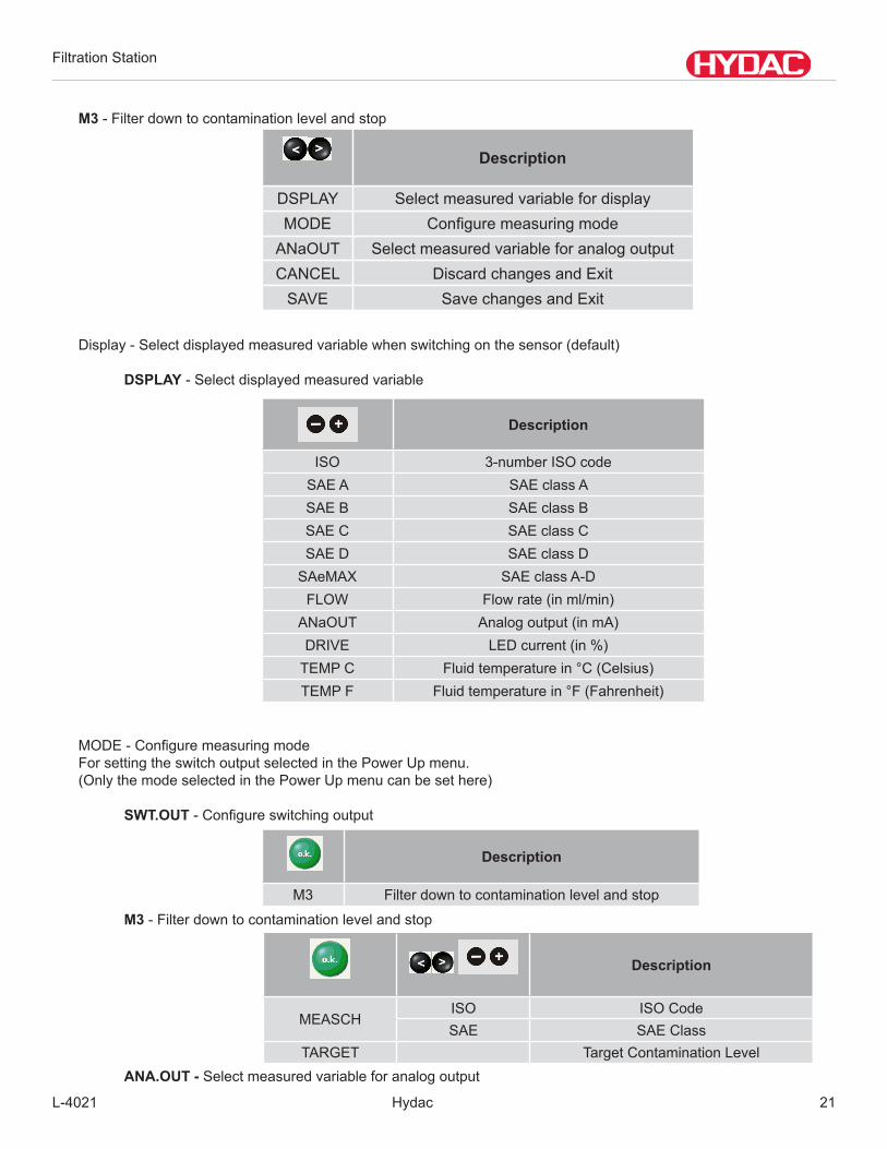
M3-Filterdowntocontaminationlevelandstop
Display-Selectdisplayedmeasuredvariablewhenswitchingonthesensor(default)
DSPLAY-Selectdisplayedmeasuredvariable
MODE-ConfiguremeasuringmodeFor setting the switch output selected in the Power Up menu. (Only the mode selected in the Power Up menu can be set here)
SWT.OUT-Configureswitchingoutput
M3-Filterdowntocontaminationlevelandstop
Description
DSPLAY SelectmeasuredvariablefordisplayMODE Configuremeasuringmode
ANaOUT SelectmeasuredvariableforanalogoutputCANCEL DiscardchangesandExitSAVE SavechangesandExit
Description
ISO 3-number ISO codeSAEA SAEclassASAEB SAEclassBSAEC SAEclassCSAED SAEclassDSAeMAX SAEclassA-D
FLOW Flow rate (in ml/min)ANaOUT Analog output (in mA)DRIVE LEDcurrent(in%)TEMPC Fluid temperature in °C (Celsius)TEMPF Fluid temperature in °F (Fahrenheit)
Description
M3 Filterdowntocontaminationlevelandstop
Description
MEASCHISO ISO CodeSAE SAEClass
TARGET TargetContaminationLevelANA.OUT - Selectmeasuredvariableforanalogoutput

Filtration Station
Hydac L-402122
Switching Behavior of the Switching Output
Mode 3 (M3) Switch output - OPEN Switch output - CLOSEDMeasurement is currently in progress and all of the last 5measuredvalues<limitor
measurement stopped
5consecutivemeasuredvalues>limit
Mode 4 (M4) Switchoutput-CLOSED Switchoutput-OPENStart or result of check
measurement after test cycle time ≥upperlimit
Measurement is currently in progress and one or more of the last5measuredvalues>limit
5consecutivemeasuredvalues≤limit or measurement stopped
Upon the test cycle time elapsing for the duration of a check
measurement
Test cycle time has elapsed Opensagainwhenmeasuredvalue<upperlimit
Restart test cycle time
Mode Single (SINGLE) Switch output - CLOSED Switch output - OPEN- Always Open
9. CS1000 TECHNICAL DATASelf-diagnosis: continuouslywitherrorindicationvia
statusLEDDisplay(onlyCS1000): 6digits,in17segmentformat
Measuredvariable: ISO/SAE/Flow/Out/Drive/TempAmbienttemperaturerange: -22°...176°F(-30°...+80°C)Storagetemperaturerange: -40°...176°F(-40°...+80°C)
relativehumidity: max.95%,non-condensingMaterialofsealing: FPM ->CS1000
Electricalsafetyclass: III(lowvoltageprotection)IPclass: IP67Weight: 3.3 lbs (1.3 kg)
Measuringrange: Displayshowsclassfrom:min:ISO7/6/5 tomax:ISO28/27/26Calibrated within the range ISO 13/11/10 ... 23/21/18
INLET: 4350 psi max./ 300 bar max. OUTLET: 4350 psi max./ 300 bar max.
Connectors: INLET:ThreadG1/4,ISO228OUTLET:ThreadG1/4,ISO228
Permissiblemeasuringflowrate: 30 - 300 ml/minPermissibleviscosityrange: 15–4635SUS(1-1000cSt)
Fluidtemperaturerange: 32°-185°F(0°-+85°C)
Gen
eral
Dat
aH
ydra
ulic
Dat
a

Filtration Station
L-4021 Hydac 23
10. FLUID MONITORING SOFTWARE (FluMoS)TheFluMoSPC-softwarepackageisfreewareandissuppliedonaCDincludedwiththeFiltrationStation.
10.1 System RequirementsThefollowinghardwareandsoftwarecomponentsarerequiredtorunFluMoS:-ProcessorPentium≥200MHz-RAM ≥64MB-GraphVGAgraphiccard,minimumresolution800x600-Harddrive≥15MBfreememory.- Interface 1 free serial or USB interface which is not being used by any other program (e.g.terminal,modemornetworksoftware).-OperatingsystemWINDOWS2000,WINDOWSXP,WINDOWSVista,WINDOWS7(32bit)-InternetExplorer≥4.0- Access rights Administrator or software installation rights
10.2 Adaptor Box — Driver InstallationBeforeinstallingthesoftwarepackage,theRS485/USBconverterdrivemustbeinstalled.
1)ConnecttheUSBportontheFiltrationStationtoyourPCviatheUSBcable.YourPCdetectsthenewhardware.
2)Select“Installfromalistorspecificlocation(Advanced)”andclick“Next”.
3)PlacetheCS1000softwareCDintheCD-ROMdrive.

Filtration Station
Hydac L-402124
4)Click“Browse”andselectthe“USBDriver”folderontheCD.
5)Click“Next.”Thedriverisnowinstalled. Afterasuccessfuldriverinstallation,clickonStart>ControlPanel>System>Hardware>Device
ManagerandnotetheCOMportnumberassignedtotheBelkinSerialonUSBPortdevice.TheCOM port number will be used when launching the FluMoS software.
Filtration Station
L-4021 Hydac 25
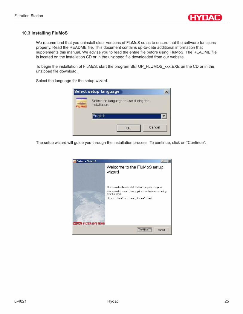
10.3 Installing FluMoS
WerecommendthatyouuninstallolderversionsofFluMoSsoastoensurethatthesoftwarefunctions properly.ReadtheREADMEfile.Thisdocumentcontainsup-to-dateadditionalinformationthat supplementsthismanual.WeadviseyoutoreadtheentirefilebeforeusingFluMoS.TheREADMEfile islocatedontheinstallationCDorintheunzippedfiledownloadedfromourwebsite.
TobegintheinstallationofFluMoS,starttheprogramSETUP_FLUMOS_xxx.EXEontheCDorinthe unzippedfiledownload.
Selectthelanguageforthesetupwizard.
Thesetupwizardwillguideyouthroughtheinstallationprocess.Tocontinue,clickon“Continue”.

Filtration Station
Hydac L-402126
Tocontinuetheinstallation,carefullyreadthroughthelicenceagreementinthenextwindowandthen click “Iaccepttheagreement.”
Duringinstallationonlytheprogramfilesarecopiedtotheinstallationdirectory.Inthenextstep,theinstallationdirectoryisdefined.Iftheinstallationdirectoryalreadyexists,youwillbeaskedifyouwishtooverwritethepath
Filtration Station
L-4021 Hydac 27
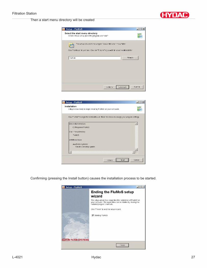
Then a start menu directory will be created
Confirming(pressingtheInstallbutton)causestheinstallationprocesstobestarted.
Filtration Station
Hydac L-402128
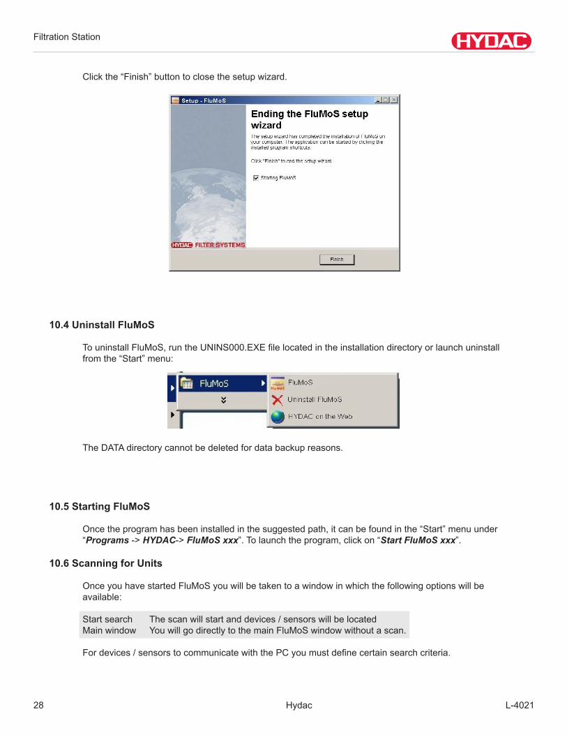
Clickthe“Finish”buttontoclosethesetupwizard.
10.4 Uninstall FluMoS
TouninstallFluMoS,runtheUNINS000.EXEfilelocatedintheinstallationdirectoryorlaunchuninstall fromthe“Start”menu:
TheDATAdirectorycannotbedeletedfordatabackupreasons.
10.5 Starting FluMoS
Oncetheprogramhasbeeninstalledinthesuggestedpath,itcanbefoundinthe“Start”menuunder “Programs->HYDAC->FluMoS xxx”.Tolaunchtheprogram,clickon“Start FluMoS xxx”.
10.6 Scanning for Units
OnceyouhavestartedFluMoSyouwillbetakentoawindowinwhichthefollowingoptionswillbe available:
Startsearch Thescanwillstartanddevices/sensorswillbelocated Main window You will go directly to the main FluMoS window without a scan.
Fordevices/sensorstocommunicatewiththePCyoumustdefinecertainsearchcriteria.
Filtration Station
L-4021 Hydac 29
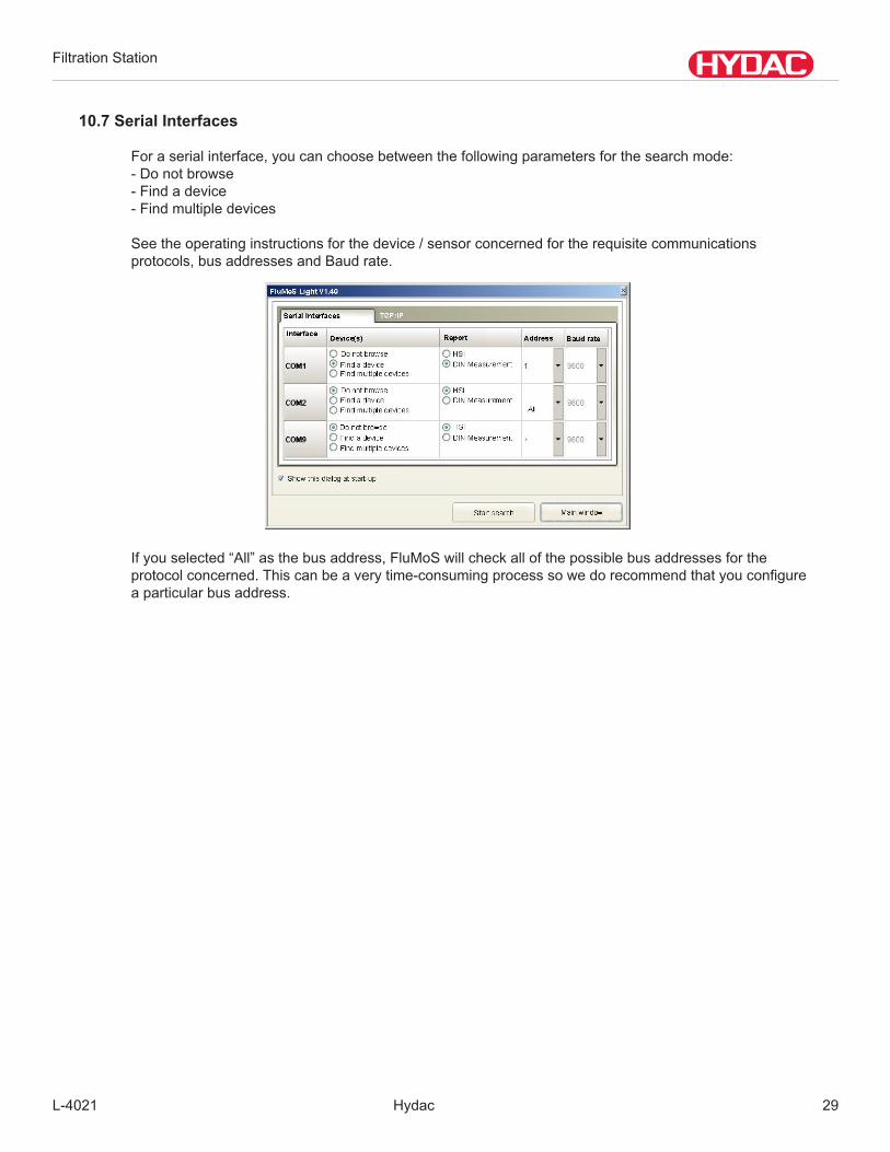
10.7 Serial Interfaces
Foraserialinterface,youcanchoosebetweenthefollowingparametersforthesearchmode: -Donotbrowse -Findadevice -Findmultipledevices Seetheoperatinginstructionsforthedevice/sensorconcernedfortherequisitecommunications protocols,busaddressesandBaudrate.
Ifyouselected“All”asthebusaddress,FluMoSwillcheckallofthepossiblebusaddressesforthe protocolconcerned.Thiscanbeaverytime-consumingprocesssowedorecommendthatyouconfigure a particular bus address.
Filtration Station
Hydac L-402130
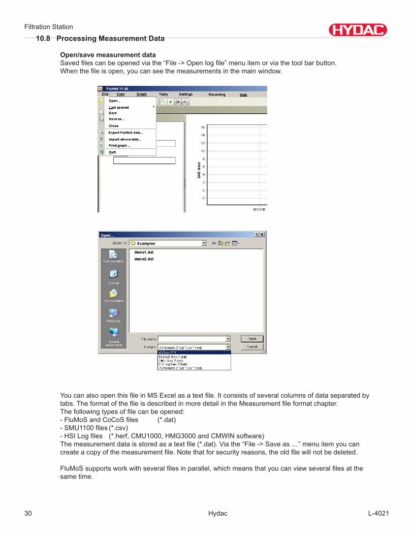
10.8 Processing Measurement Data
Open/save measurement data Savedfilescanbeopenedviathe“File->Openlogfile”menuitemorviathetoolbarbutton. Whenthefileisopen,youcanseethemeasurementsinthemainwindow.
YoucanalsoopenthisfileinMSExcelasatextfile.Itconsistsofseveralcolumnsofdataseparatedby tabs.TheformatofthefileisdescribedinmoredetailintheMeasurementfileformatchapter. Thefollowingtypesoffilecanbeopened: -FluMoSandCoCoSfiles (*.dat) -SMU1100files(*.csv) -HSILogfiles (*.herf,CMU1000,HMG3000andCMWINsoftware) Themeasurementdataisstoredasatextfile(*.dat).Viathe“File->Saveas…”menuitemyoucan createacopyofthemeasurementfile.Notethatforsecurityreasons,theoldfilewillnotbedeleted.
FluMoSsupportsworkwithseveralfilesinparallel,whichmeansthatyoucanviewseveralfilesatthe same time.
Filtration Station
L-4021 Hydac 31
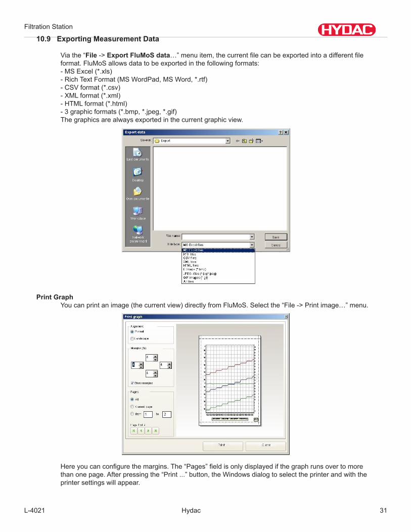
10.9 Exporting Measurement Data
Viathe“File->Export FluMoS data…”menuitem,thecurrentfilecanbeexportedintoadifferentfile format.FluMoSallowsdatatobeexportedinthefollowingformats: -MSExcel(*.xls) -RichTextFormat(MSWordPad,MSWord,*.rtf) -CSVformat(*.csv) -XMLformat(*.xml) - HTML format (*.html) -3graphicformats(*.bmp,*.jpeg,*.gif) Thegraphicsarealwaysexportedinthecurrentgraphicview.
Print Graph Youcanprintanimage(thecurrentview)directlyfromFluMoS.Selectthe“File->Printimage…”menu.
Hereyoucanconfigurethemargins.The“Pages”fieldisonlydisplayedifthegraphrunsovertomore thanonepage.Afterpressingthe“Print...”button,theWindowsdialogtoselecttheprinterandwiththe printer settings will appear.
Filtration Station
Hydac L-402132
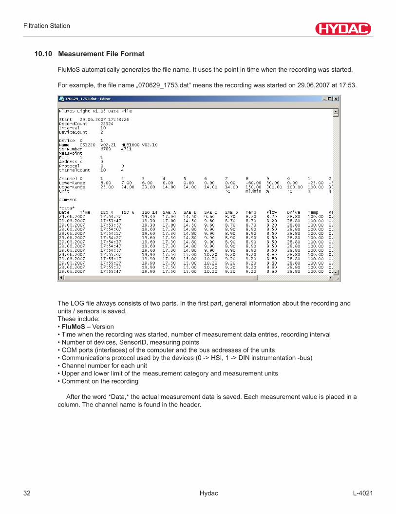
10.10 Measurement File Format
FluMoSautomaticallygeneratesthefilename.Itusesthepointintimewhentherecordingwasstarted. Forexample,thefilename„070629_1753.dat“meanstherecordingwasstartedon29.06.2007at17:53.
TheLOGfilealwaysconsistsoftwoparts.Inthefirstpart,generalinformationabouttherecordingand units/sensorsissaved. Theseinclude: • FluMoS – Version •Timewhentherecordingwasstarted,numberofmeasurementdataentries,recordinginterval •Numberofdevices,SensorID,measuringpoints • COM ports (interfaces) of the computer and the bus addresses of the units •Communicationsprotocolusedbythedevices(0->HSI,1->DINinstrumentation-bus) • Channel number for each unit • Upper and lower limit of the measurement category and measurement units • Comment on the recording Aftertheword*Data,*theactualmeasurementdataissaved.Eachmeasurementvalueisplacedina column. The channel name is found in the header.
Filtration Station
L-4021 Hydac 33
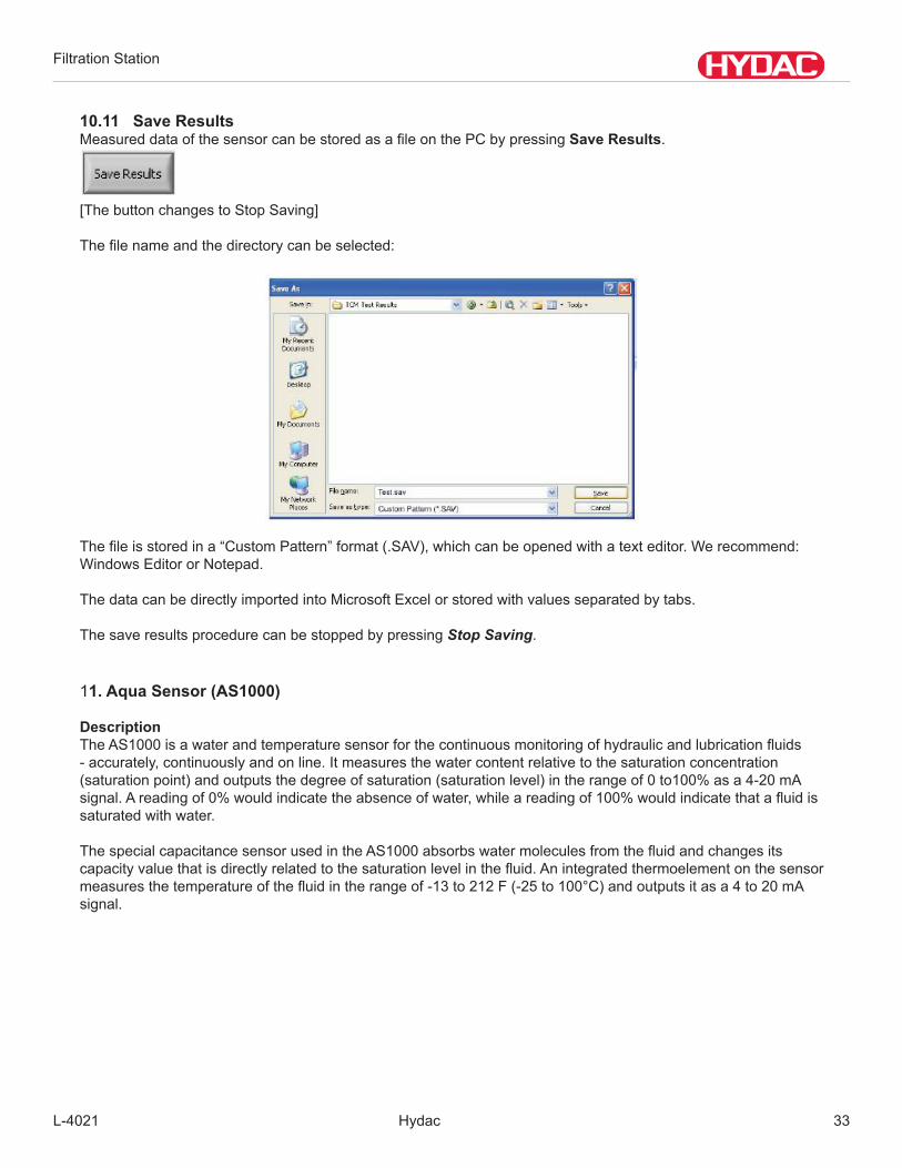
10.11 Save ResultsMeasureddataofthesensorcanbestoredasafileonthePCbypressingSave Results.
[ThebuttonchangestoStopSaving]
Thefilenameandthedirectorycanbeselected:
Thefileisstoredina“CustomPattern”format(.SAV),whichcanbeopenedwithatexteditor.Werecommend:WindowsEditororNotepad.
ThedatacanbedirectlyimportedintoMicrosoftExcelorstoredwithvaluesseparatedbytabs.
ThesaveresultsprocedurecanbestoppedbypressingStop Saving.
11. Aqua Sensor (AS1000)
DescriptionTheAS1000isawaterandtemperaturesensorforthecontinuousmonitoringofhydraulicandlubricationfluids-accurately,continuouslyandonline.Itmeasuresthewatercontentrelativetothesaturationconcentration(saturationpoint)andoutputsthedegreeofsaturation(saturationlevel)intherangeof0to100%asa4-20mAsignal.Areadingof0%wouldindicatetheabsenceofwater,whileareadingof100%wouldindicatethatafluidissaturated with water.
ThespecialcapacitancesensorusedintheAS1000absorbswatermoleculesfromthefluidandchangesitscapacityvaluethatisdirectlyrelatedtothesaturationlevelinthefluid.Anintegratedthermoelementonthesensormeasuresthetemperatureofthefluidintherangeof-13to212F(-25to100°C)andoutputsitasa4to20mAsignal.
Filtration Station
Hydac L-402134
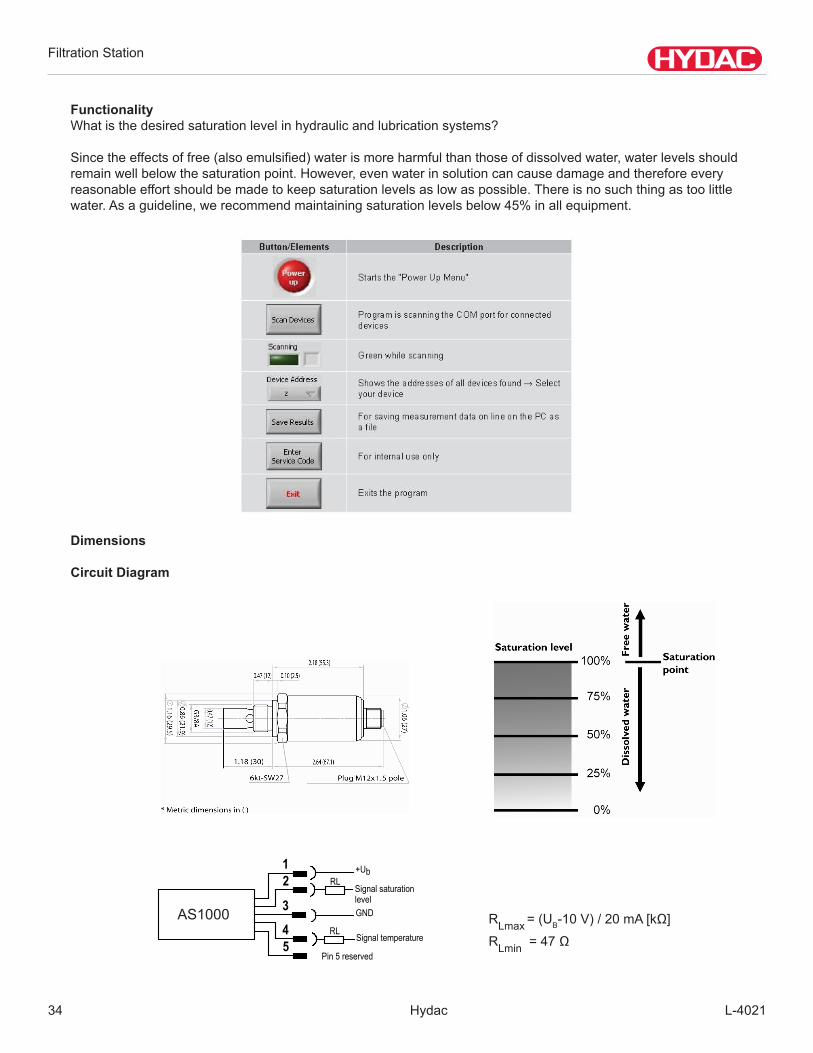
FunctionalityWhatisthedesiredsaturationlevelinhydraulicandlubricationsystems?
Sincetheeffectsoffree(alsoemulsified)waterismoreharmfulthanthoseofdissolvedwater,waterlevelsshouldremainwellbelowthesaturationpoint.However,evenwaterinsolutioncancausedamageandthereforeeveryreasonableeffortshouldbemadetokeepsaturationlevelsaslowaspossible.Thereisnosuchthingastoolittlewater.Asaguideline,werecommendmaintainingsaturationlevelsbelow45%inallequipment.
Dimensions
Circuit Diagram
Signal saturation level
TWS-C-M
2 1
3
4
+Ub
Signal temperature RL
RL
5
GND
Pin5reserved
RLmax = (UB-10V)/20mA[kΩ]
RLmin=47Ω
AS1000

Filtration Station
L-4021 Hydac 35
INPUT DATA Measuringrange(saturationlevel): 0...100%Measuringrange(temperature): -13...212F/25..+100°C
Operatingpressure: Max.725psi,/max.50barOverloadpressure: Max.9135psi/max.630bar
Partsincontactwithmedia: stainlesssteel,sealvitonorEPDM,ceramicwithevaporatedmetal
OUTPUT DATA Humidity measurement
Outputsignal(saturationlevel): 4 .. 20 mA Calibratedaccuracy: ≤±2%FSmax.
Accuracyinmediameasurements: ≤±3%FStyp.Pressure-dependent: +0.02%FS/bar
Temperaturemeasurement:Outputsignal(temperature): 4 .. 20 mA
Accuracy: *±2%FSmax.AMBIENT CONDITIONS
Nominaltemperaturerange(saturationlevelmeasuring: 32...194F/0..+90°C
Ambienttemperaturerange: -40...212F/-40..+100°CFluidtemperaturerange: -40...257F-40..+125°C
Viscosityrange: 32 .. 23175 SUS Flowvelocity: <16ft/s
Mediatolerance: mineraloilbasedfluids,naturalandsyntheticestersCEmark: EN50081-1,EN50081-2
EN50082-1,EN61000-6-2TypeofProtectionacc.DIN40050: IP67
OTHER DATA Supplyvoltage: 12..32VDC
Residualripplesupplyvoltage: ≤5%Mechanicalconnection: G3/8ADIN3852
Torquerating: 18.5 ft-lbs. Electricalconnection: M12x1,5pole(DINVDE0627)
Pin1: +UbPin2: SignalsaturationlevelPin3: 0V/GNDPin4: Signal temperaturePin5: not connected
Reversepolarityprotectionofthesupplyvoltage,excessvoltage,overrideandshortcircuitprotection:
standard
11.1 AS1000 TECHNICAL DATA

Filtration Station
Hydac L-402136
Flow Rate: 3-8 GPM (1.4-30.3 l/min)/9GPM (34 l/m)
Max Pressure: 35 PSI (2.4 bar)Viscosity Limit: 1,000SUS
Weight (Approx.): 195 lbs.(117.93 kg)Operating Temperature (Hydraulics):
Depending on Viscosity-20°F to 150°F(-29°Cto65°C)
Operating Temperature (Electronics):Up to 95% non-condensing humity
32°F to 113°F(0°C to 45°C)
Environmental Rating:The Filter Caddy should not be exposed to ex-
treme weather conditions including rain and snowNEMA4
Power Requirements: 120/220VAC50/60HZ@15A
CyclethehydraulicsystemthoroughlyinordertoflushthecontaminatedfluidfromthelinesandsystemcomponentssoallthefluidinasystemwillbefilteredthroughtheFiltrationStation.
Precautionary Measures - Follow these simple rules to keep the Filtration Station in top working condition to providequalityfilteringforyearstocome.
The PumpNeverstartuporrunadrypump.Thiswillcausegalling,seizingordestructivewearbetweentherotors,end plates and casting.
Fluid TypesTheFiltrationStationisdesignedforthetransferandfilteringofhydraulicandlubricationoilsonly!Itisnottobeusedforhighlyvolatilefluidssuchasgasolineorpaintthinners.Pleasecontactthefactoryforusesotherthanthosespecified.
Ambient TemperatureThe maximum operating temperature for the Filtration Station is 150°F. Higher temperatures could damage the hoses.
Electric MotorIt is recommended that the electric motor be replaced with a new motor only.
Replacement PartsSinceminimumrepairserviceisgenerallyrequiredontheseunits,itisrecommendedthatanyfailedpartsbereplaced with new parts.

Filtration Station
L-4021 Hydac 37
12 MAINTENANCE PROCEDURESAchievingthebestfilteringefficiency-Inordertoensurethepropercleaningofthereservoirfluid,positiontheendsofboththeinletandtheoutlethoseortubeasfarapartaspossibleinsidethereservoir-preferablyondifferentsidesoftheexistingbaffle
REPLACEMENT ELEMENTS
9 inch Elements 18 inch Elements 27 inch ElementsModel Code Part No. Model Code Part No. Model Code Part No.5.03.09D03BN 2060528 5.03.18D03BN 2060430 5.03.27D03BN 2065003
5.03.09D03BN/-V 2056713 5.03.18D03BN/-V 2071680 5.03.27D03BN/-V 20828555.03.09D05BN 2060529 5.03.18D05BN 2060431 5.03.27D05BN 2065004
5.03.09D05BN/-V 2056714 5.03.18D05BN/-V 2056457 5.03.27D05BN/-V 20734885.03.09D10BN 2060530 5.03.18D10BN 2060432 5.03.27D10BN 2065005
5.03.09D10BN/-V 2056715 5.03.18D10BN/-V 2056492 5.03.27D10BN/-V 20564935.03.09D20BN 2060531 5.03.18D25BN 2060433 5.03.27D20BN 2065006
5.03.09D20BN/-V 2056716 5.03.18D25BN/-V 2072428 5.03.27D20BN/-V 020960525.03.09D40AM 2075265 5.03.18D40AM 02098017 5.03.27D40AM 2088358
HK/HJ (connector element) 2056730 — — — —
VISUAL INDICATORModel Code Part No.
D5-30 02702213D5V-30 02702561
Filtration Station
Hydac L-402138
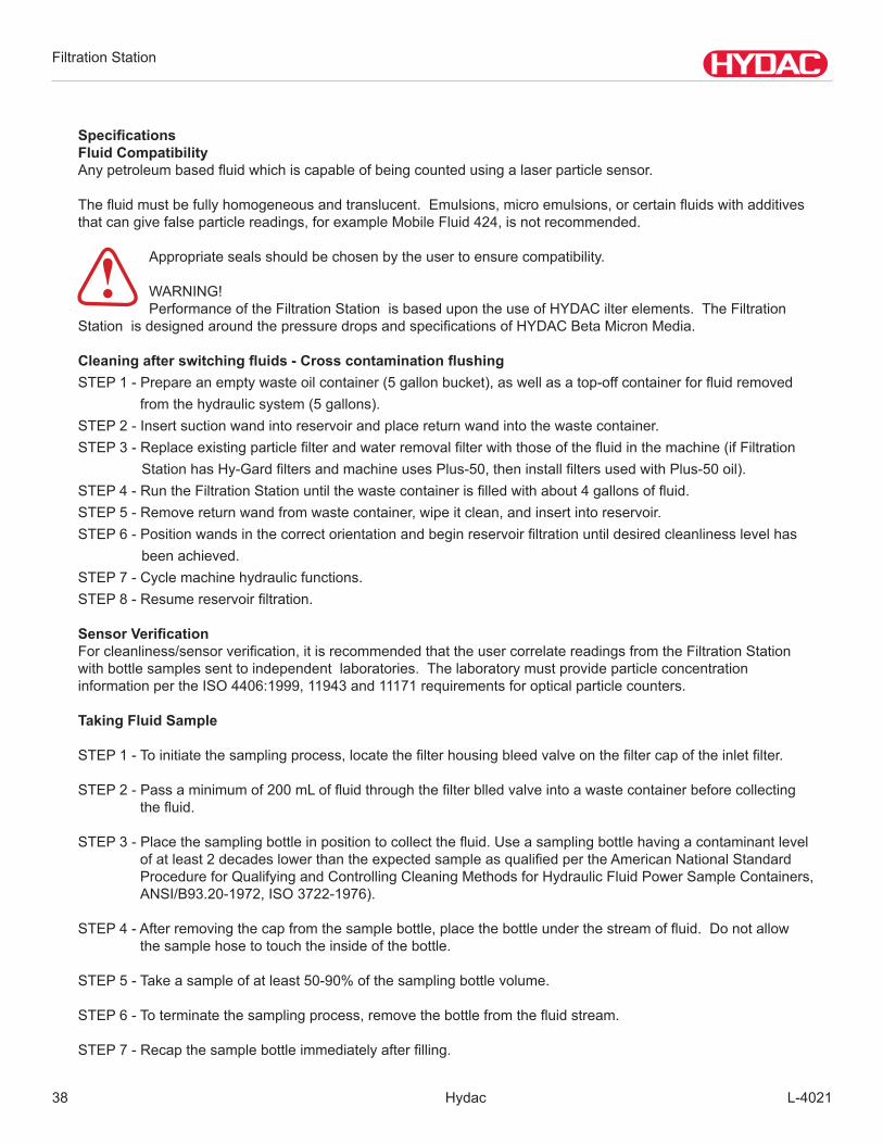
SpecificationsFluid CompatibilityAnypetroleumbasedfluidwhichiscapableofbeingcountedusingalaserparticlesensor.
Thefluidmustbefullyhomogeneousandtranslucent.Emulsions,microemulsions,orcertainfluidswithadditivesthatcangivefalseparticlereadings,forexampleMobileFluid424,isnotrecommended.
Appropriate seals should be chosen by the user to ensure compatibility.
WARNING!PerformanceoftheFiltrationStationisbasedupontheuseofHYDACilterelements.TheFiltration
StationisdesignedaroundthepressuredropsandspecificationsofHYDACBetaMicronMedia.
Cleaning after switching fluids - Cross contamination flushingSTEP1-Prepareanemptywasteoilcontainer(5gallonbucket),aswellasatop-offcontainerforfluidremoved
from the hydraulic system (5 gallons).STEP2-Insertsuctionwandintoreservoirandplacereturnwandintothewastecontainer.STEP3-Replaceexistingparticlefilterandwaterremovalfilterwiththoseofthefluidinthemachine(ifFiltration
StationhasHy-GardfiltersandmachineusesPlus-50,theninstallfiltersusedwithPlus-50oil).STEP4-RuntheFiltrationStationuntilthewastecontainerisfilledwithabout4gallonsoffluid.STEP5-Removereturnwandfromwastecontainer,wipeitclean,andinsertintoreservoir.STEP6-Positionwandsinthecorrectorientationandbeginreservoirfiltrationuntildesiredcleanlinesslevelhas
beenachieved.STEP7-Cyclemachinehydraulicfunctions.STEP8-Resumereservoirfiltration.
Sensor VerificationForcleanliness/sensorverification,itisrecommendedthattheusercorrelatereadingsfromtheFiltrationStationwithbottlesamplessenttoindependentlaboratories.ThelaboratorymustprovideparticleconcentrationinformationpertheISO4406:1999,11943and11171requirementsforopticalparticlecounters.
Taking Fluid Sample
STEP1-Toinitiatethesamplingprocess,locatethefilterhousingbleedvalveonthefiltercapoftheinletfilter.
STEP2-Passaminimumof200mLoffluidthroughthefilterblledvalveintoawastecontainerbeforecollectingthefluid.
STEP3-Placethesamplingbottleinpositiontocollectthefluid.Useasamplingbottlehavingacontaminantlevelofatleast2decadeslowerthantheexpectedsampleasqualifiedpertheAmericanNationalStandardProcedureforQualifyingandControllingCleaningMethodsforHydraulicFluidPowerSampleContainers,ANSI/B93.20-1972,ISO3722-1976).
STEP4-Afterremovingthecapfromthesamplebottle,placethebottleunderthestreamoffluid.Donotallowthe sample hose to touch the inside of the bottle.
STEP5-Takeasampleofatleast50-90%ofthesamplingbottlevolume.
STEP6-Toterminatethesamplingprocess,removethebottlefromthefluidstream.
STEP7-Recapthesamplebottleimmediatelyafterfilling.
!
Filtration Station
L-4021 Hydac 39
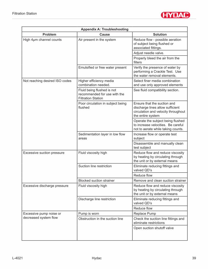
Appendix A: TroubleshootingProblem Cause Solution
High 4µm channel counts Air present in the system Reduceflow-possibleaerationofsubjectbeingflushedorassociatedfittings.Adjustneedlevalve.Properly bleed the air from the filters
Emulsifiedorfreewaterpresent Verify the presence of water by performing a Crackle Test. Use thewaterremovalelements.
Not reaching desired ISO codes Higherefficiencymediacombination needed.
Selectfinermediacombinationanduseonlyapprovedelements
Fluidbeingflushedisnotrecommended for use with the Filtration Station
Seefluidcompatibilitysection.
Poor circulation in subject being flushed
Ensurethatthesuctionanddischargelinesallowsufficientcirculationandvelocitythroughoutthe entire systemOperatethesubjectbeingflushedtoincreasevelocities.Becarefulnot to aerate while taking counts.
Sedimentationlayerinlowflowareas
IncreasefloworoperatetestsubjectDisassembleandmanuallycleantest subject
Excessivesuctionpressure Fluidviscosityhigh Reduceflowandreduceviscosityby heating by circulating through the unit or by external means
Suction line restriction EliminatereducingfittingsandvalvedQD’sReduceflow
Blocked suction strainer RemoveandcleansuctionstrainerExcessivedischargepressure Fluidviscosityhigh Reduceflowandreduceviscosity
by heating by circulating through the unit or by external means
Dischargelinerestriction EliminatereducingfittingsandvalvedQD’sReduceflow
Excessivepumpnoiseordecreasedsystemflow
Pump is worn Replace PumpObstruction in the suction line Checkthesuctionlinefittingsand
eliminate restrictionsOpensuctionshutoffvalve

Filtration Station
Hydac L-402140
Problem Cause SolutionUnchanging or consistently high ISO codes
Particle monitor blocked with contamination
Consult enclosed particle monitor manual or contact the manufacturer for cleaning instructions
Fluidbeingflushedisnotrecommended for use with the Super Caddy
Seefluidcompatibilitysection.
Erraticparticlemonitoroperation Particle monitor bad Replace Particle MonitorUnit is connected to power source with no lights being illuminated
Tripped Circuit Breaker Reset Main Circuit BreakerBlown Fuse Test and/or Replace control power
circuit fuseDefectivePowerCord Test Power Cord for continuity.
Replace/Repair as necessary.Unit will not start. Start light is not flashingornotilluminated.
Stop button left in the depressed position
Pull stop button to extended position. Start button should beflashingsignalinga“Ready”condition
Unit will not start. Start light is a solid green.
Unit will not start. Start light is a solid green.
Speed control dial is at the ‘O” position
Turn speed control knob clockwise.
Blown Armature Fuse Test and/or Replace Armature fuse on side of electrical cabinet
Blown Line Fuse (F1) Test and/or Replace Line fuse on DCDrivecard..
No Fluid Flow Speedcontroldialisatthe“O”position
Turn speed control knob clockwise. Check for motor fan rotation. If motor is not rotating checkDCdrivefuses.
SuctionWandisnotbelowfluidlevel
Ensurethatsuctionwandisbelowfluidlevel.Donotrunpumpdry.
Air Leak in suction hose Inspect hose for cracks or cuts. Checkforlooseinletfittings.Repair replace as needed.
Inlet“Y”strainerplugged Removesuctionwandfromfluidsource.Disconnectcaddyfrompowersource.Removedrainplugfrominlet“Y”strainer.Drainintosuitablecontainer.Removehexbushingfrom“Y”strainer.Removeandinspectscreen.Clean or replace the screen and reassemble. Place suction want intofluidsource.Startunitandcheck for leaks.
Suction wand is blocked Check suction wand ensure that it is not blocked or in full contact withbottomoffluidreservoir
Filtration Station
L-4021 Hydac 41
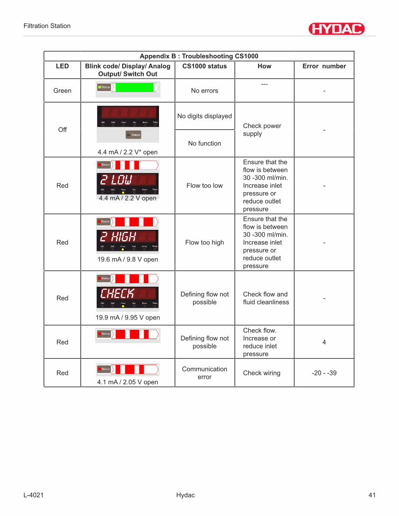
Appendix B : Troubleshooting CS1000LED Blink code/ Display/ Analog
Output/ Switch OutCS1000 status How Error number
Green No errors---
-
Off
4.4 mA / 2.2 V* open
No digits displayedCheck power supply -
No function
Red
4.4 mA / 2.2 V open
Flow too low
Ensurethattheflowisbetween30 -300 ml/min. Increase inlet pressure or reduce outlet pressure
-
Red
19.6mA/9.8Vopen
Flow too high
Ensurethattheflowisbetween30 -300 ml/min. Increase inlet pressure or reduce outlet pressure
-
Red
19.9 mA / 9.95 V open
Definingflownotpossible
Checkflowandfluidcleanliness -
Red Definingflownotpossible
Checkflow.Increase or reduce inlet pressure
4
Red4.1 mA / 2.05 V open
Communication error Check wiring -20 - -39
Filtration Station
Hydac L-402142
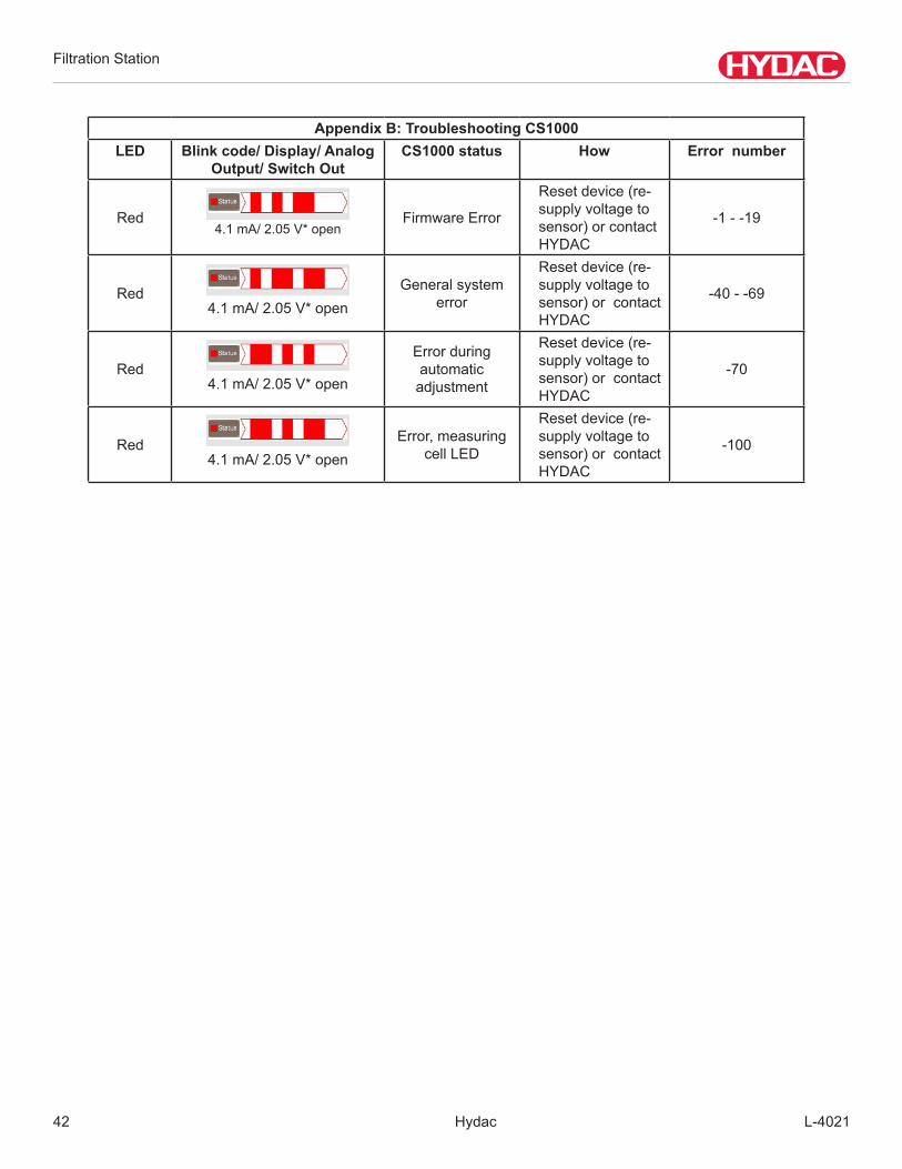
Appendix B: Troubleshooting CS1000LED Blink code/ Display/ Analog
Output/ Switch OutCS1000 status How Error number
Red4.1 mA/ 2.05 V* open
FirmwareError
Resetdevice(re-supplyvoltagetosensor) or contact HYDAC
-1 - -19
Red4.1 mA/ 2.05 V* open
General system error
Resetdevice(re-supplyvoltagetosensor) or contact HYDAC
-40--69
Red4.1 mA/ 2.05 V* open
Errorduringautomatic
adjustment
Resetdevice(re-supplyvoltagetosensor) or contact HYDAC
-70
Red4.1 mA/ 2.05 V* open
Error,measuringcellLED
Resetdevice(re-supplyvoltagetosensor) or contact HYDAC
-100

Filtration Station
L-4021 Hydac 43
Particle Count / 100 ml Particle Count / 100 ml
Class More Than Up to (and including) Class More Than Up to
(and including)0 0.00 0.01 15 160 3201 0.01 0.02 16 320 6402 0.02 0.04 17 640 1,3003 0.04 0.08 18 1,300 2,5004 0.08 0.16 19 2,500 5,0005 0.16 0.32 20 5,000 10,0006 0.32 0.64 21 10,000 20,0007 0.64 1.3 22 20,000 40,0008 1.30 2.5 23 40,000 80,0009 2.50 5 24 80,000 160,000
10 5 10 25 160,000 320,00011 10 20 26 320,000 640,00012 20 40 27 640,000 1,300,00013 40 80 28 1,300,000 2,500,00014 80 160
APPENDIX C
C.1 ISO 4406 AND SAE AS 4059 CLASSES
ISO 4406:1999InISO4406particlecountsaredeterminedcumulatively,i.e.>4µm(c),>6µm(c)and>14µm(c)(manuallybyfilteringthefluidtroughanautomaticallyusingparticlecounters)andallocatedtomeasurementreferences.Thegoalofallocatingparticlecountstoreferencesistofacilitatetheassessmentoffluidcleanlinessratings.In1999the“old”ISO4406wasrevisedandthesizerangesoftheparticlesizesundergoinganalysisredefined.The counting method and calibration were also changed.Thisisimportantfortheuserinhiseverydaywork:Eventhoughtthemeasurementreferencesoftheparticlesundergoinganalysishavechanged,thecleanlinesscodewillchangeonlyinindividualcases.Whendraftingthe“new”ISO4406itwasensuredthatnotalltheexistingcleanlinessprovisionsforsystemshadtobechanged.
ISO 4406:1999 TableAllocationofparticlecountstocleanlinessclasses:
Note: increasing the measurement reference by 1 causes the particle count to double.
Filtration Station
Hydac L-402144
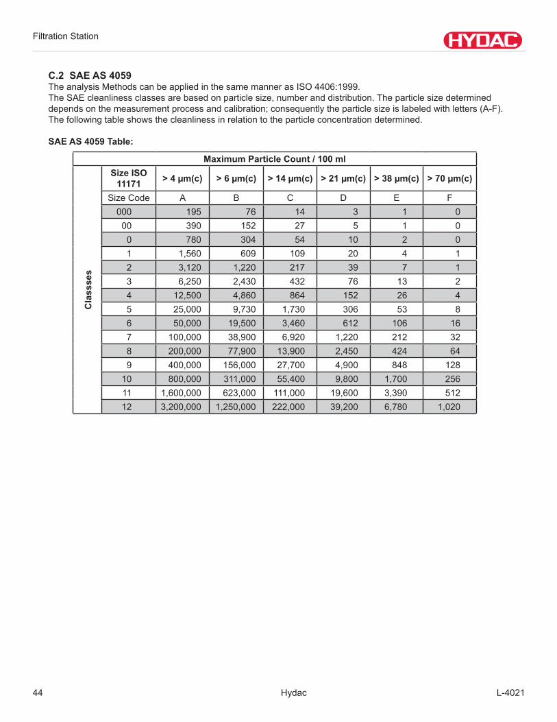
C.2 SAE AS 4059TheanalysisMethodscanbeappliedinthesamemannerasISO4406:1999.TheSAEcleanlinessclassesarebasedonparticlesize,numberanddistribution.Theparticlesizedetermineddependsonthemeasurementprocessandcalibration;consequentlytheparticlesizeislabeledwithletters(A-F).The following table shows the cleanliness in relation to the particle concentration determined.
SAE AS 4059 Table:
Maximum Particle Count / 100 mlSize ISO
11171 > 4 µm(c) > 6 µm(c) > 14 µm(c) > 21 µm(c) > 38 µm(c) > 70 µm(c)
SizeCode A B C D E F000 195 76 14 3 1 0
00 390 152 27 5 1 00 780 304 54 10 2 01 1,560 609 109 20 4 12 3,120 1,220 217 39 7 13 6,250 2,430 432 76 13 24 12,500 4,860 864 152 26 45 25,000 9,730 1,730 306 53 86 50,000 19,500 3,460 612 106 167 100,000 38,900 6,920 1,220 212 328 200,000 77,900 13,900 2,450 424 649 400,000 156,000 27,700 4,900 848 128
10 800,000 311,000 55,400 9,800 1,700 25611 1,600,000 623,000 111,000 19,600 3,390 51212 3,200,000 1,250,000 222,000 39,200 6,780 1,020
Cla
ssse
s

Filtration Station
L-4021 Hydac 45
C.3 NAS 1638LikeISO4406,NAS1638describesparticleconcentrationsinliquids.TheanalysismethodscanbeappliedinthesamemannerasISO4406:1987.
IncontrasttoISO4406,certainparticlerangesarecountedinNAS1638andattributedtomeasurementreferences.
Thefollowingtableshowsthecleanlinessclassesinrelationtotheparticleconcentrationanalyzed.
Increasingtheclassby1causestheparticlecounttodoubleonaverage.
Theparticlecountsofclass10arebold-facedintheabovetable.
Figure 2. Microscopic Examination of an Oil Sample (100 ml) Magnification 100x (NAS 10)
Filtration Station
Hydac L-402146
Filtration Station
L-4021 Hydac 47
Filtration Station
Hydac L-402148

Filtration Station
L-4021 Hydac 49
Filtration Station
Hydac L-402150
Filtration Station
L-4021 Hydac 51

Filtration Station
Hydac L-402152

Internet:www.hydac.comE-Mail:[email protected]