filtration part i.. 1 definition filtration is a process of separating dispersed particles from a...
TRANSCRIPT

FILTRATION
PART I.

1 Definition
Filtration is a process of separating dispersed particles from a dispersing fluid by means of porous media. The dispersing medium can be a gas (or gas mixture) or a liquid.
Upstream Downstream
Filter
Channel wall
Dispersed particles
Dispersing fluid
Particles deposited inside the filter
Filter thickness
Face of the filter with „filter cake“ of deposited particles
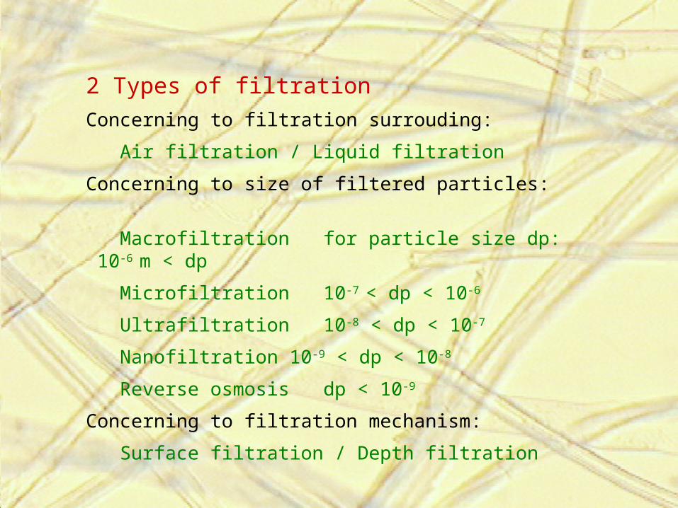
2 Types of filtration
Concerning to filtration surrouding:
Air filtration / Liquid filtration
Concerning to size of filtered particles:
Macrofiltration for particle size dp: 10-6 m < dp
Microfiltration 10-7 < dp < 10-6
Ultrafiltration 10-8 < dp < 10-7
Nanofiltration 10-9 < dp < 10-8
Reverse osmosis dp < 10-9
Concerning to filtration mechanism:
Surface filtration / Depth filtration

2.1 Relative size of common filtered particles

Asbestos 0.2 fiber/cc confirmed carcinogen
Benzene 0.3 mg/m3 confirmed carcinogen
Bromine 0.66 mg/m3
Cadmium 0.002 mg/m3 suspected carcinogen
Carbon dioxide 9,000 mg/m3
Carbon disulfide 31 mg/m3
Carbon monoxide 29 mg/m3
Carbon tetrachloride 31 mg/m3 animal carcinogen
Chlorine 1.5 mg/m3
Chloroform 49 mg/m3 suspected carcinogen
Cresol 22 mg/m3
Ethanol 1,880 mg/m3
Fluorine 1.6 mg/m3
Formaldehyde 0.37 mg/m3 animal carcinogen
Hydrogen cyanide 11 mg/m3
Iodine 1 mg/m3
Iron oxide (fume) 5 mg/m3
Isopropyl alcohol 980 mg/m3
Lead (fume) 0.2 mg/m3
Manganese 0.2 mg/m3
Mercury 0.01 mg/m3
Methanol 260 mg/m3
Nitric acid 30 mg/m3
Nitrogen dioxide 5.6 mg/m3
Propane asphyxiant
Selenium 0.2 mg/m3
Sulfur dioxide 5.2 mg/m3
Sulfuric acid 1 mg/m3
Tellurium 0.1 mg/m3
Tetraethyl lead 0.1 mg/m3
Toluene 188 mg/m3
Turpentine 560 mg/m3
Vinyl chloride 13 mg/m3 confirmed carcinogen
Zinc oxide (fume) 5 mg/m3
2.2 List of airborne pollutants and the American Industrial Hygiene Association, 1993, approved safe levels

2.3 Surface filtration
All particles which are bigger than pores are captured on the flat filter surface and create „filter cake“. It is typical for example for woven fabric or spunbond filters. Thus for these filters the pores distribution and permeability are important properties. Flat filtration is more common for liquid filtration.
Advantage: - It is very important for the cleanable filters – filter cake is possible to release
from the filter surface.- It is possible to capture all particles, which are bigger than pore size.
Disadvantage: - Filter properties are very instable in time (filter is clogged).- Pressure drop is higher
Direction of flow
Textile filter expressed as a set of cylinders placed in parallel
Captured particles

2.4 Deep filtrationDepth filter are able to capture particles that are too small to be sieved out as in flat filtration. Particles, which can be a lot of smaller than the distances between the fibers penetrate into the fiber structure. Filtered particles are captured in terms of the filtration mechanisms. This type of the filtration process is important for the most of filter applications. Next chapters about filtration variables, properties and mechanisms refer first of all to the deep filtration.
Advantages: - Longer lifetime- Better relation between pressure drop and filtr efficiency
Disadvantages:- Usually it is not possible to clean clodged filter
Direction of flow
Textile filter expressed as a set of cylinders placed in parallel
Captured particles

4 Principle of filtration - relation between filtration variables and filter properties.
Filtration variables• Filter variables• Flowing medium
variables• Captured particles
variables
Filtration properties• Efficiency• Pressure drop• Lifetime• Resistivity against
surrounding conditions
• Others (permeability, porosity...)
Filtration mechanisms• Diffusion deposition• Direct interception• Inertial deposition• Electrostatic
deposition• Sieve effect
It´s simple to say “what is filtration” but difficult to describe relations between filter properties and the main filtration variables which influence the filtration process

Filter efficiency
It is the ratio of particles captured by a filter over the total number of particles found in the air upstream of the filter. Filter efficiency can either be based on specific particle size ranges or based on the total number of particles of all sizes.
4.1 Filtration properties – output of the filtration process I.
100.12
1
G
GE
Efficiency can be defined by formula 1, where G1 is an amount of penetrated particles (which haven´t been captured) and G2 is total amount of particles upstream formula 1.
Expression G1/G2 is named „Penetration“ of filter
Efficieny is changing during the filtration process (see chapter 6.3.4 Nonstationary filtration)

Pressure drop Pressure drop indicates the restance to flow. It is defined as a difference between the pressure of flowing media upstream and downstream of the filter. For expression of pressure drop is necessary to assign air flow or air velocity (linear relation).
p = p1 - p2, where p1 is pressure drop upstream and p2 downstream
of the filter. Pressure drop is changed during the filtration proces (see chapter 6.3.4 Nonstationary filtration).
Filtration properties – output of the filtration process II.
Filter lifetimeFilter lifetime determines the time when the filter must be removed. It is defined as a time or as an amount of the filtered particles, which are loaded into the filter until the filter is full.
According to EN 779 standard the filter lifetime is defined as a „Dust holding capacity“:
J = Es.mp where Es is mean filter efficiency and mp is the amount of the
particles loaded into the filter until the final pressure drop (250 or 400 Pa) was reached

Other properties I.
Permeability
It is the ability of a material to allow the passage of a liquid or gas through porous material. It is possible to find more defininitions, whic depend on the level of simplification:
1) According to EDANA 140.1 standard it is defined by formula:
where Ms is permeability (l/dm2/min), Q is the flow (l/min)and A is the filter surface. Permeability is tested with the
pressure drop 196 Pa (98,1 Pa for some standards)
2) According to the Darcy´s law the permeability is defined by formula:
where K is permeability (m/Pa/sec) and p is the pressure drop (Pa).
3) According to the Darcy,s law is possible to define permeability as a „permeability coefficient“ defined by formula:
where k1 is the permeability coefficient (m2), is the dynamic viskosity (Pa.sec), and h (m) is the thickness of the filter.
Filtration properties – output of the filtration process III.
A
QM S
pA
QK
.
pA
hQk
.
..1

4. According Hagen-Dupuit-D´Arcy´s model is permeability defined as:
where K3 is permeability coefficient and C is form coefficient.
This model is suitable for higher flow of viscose liquid (such as water etc…). When we compare HDD model with D´Arcy´s law, the main difference is nonlinear relation between flow and pressure drop.
Permeabilityof laminated textiles
For simple D´Arcy´s law it is possible to deduce relation between the permeability of one layer and more layers. For most of the applications we can assume that the flow through the laminated textile is the some as flow through one layer. Than the total pressure drop and total permeability are defined:
and ,
where pi and K1i are pressure drop and peremability coefficients of each layers
2
3
...
..
.Q
A
hCQ
AK
hp
i
it pp i itotal KK 11
11

Other properties II.
Porosity and pore size
Porosity of porous medium is defined as a percentage of the porous material volume not occupied by fibers.
Very important is size or size distribution of pores, which depends on the pore definition and on the used test method.
Testing methods:
1. Image analysis of 2D microscopic wiew – direct method
2. Sifting of defined particles through the textile
3. Penetration of liquid agent into the textile – relation between pore size and surface tension of liquid.
a) Wetting agent is pushed away from textile due to pressured gas – Bubble point method
b) Non-wetting agent is pushed into the textile – Mercury porosimetry
For more informations see subject „High functional textiles“.
Filtration properties – output of the filtration process IV.

Description of simple Bubble point method:We assume circular pores. Wetting liquid (wetting angle = 0) try to go through the pores due to wetting force F= .D. . Against this force we can act by pressured gas (Fp = p.Apore). D is pore diameter, is liquid surface tension, p is gas pressure and Apore is pore cross section surface. When the first bubble of gas is going
through the pore – both forces are in equilibrium. At first bubbles are going through the maximum pore. When we can measure flow rate of gas is possible to measure the distribution of pore sizes.
D
F = . . D
Fp = p . Apore
textile
Wetting agent
bubble
4.2 Statinary and nonstacionary filtrationIt is important that the filtration properties are changing during the filtration
process. A captured particle, since it occupies a finite space, becomes part of the filter structure, able to contribute both to pressure drop and to filtration efficiency. When we neglect this assumption the filtration process is named „stationary“. It is possible in the beginning of the filtration process. When we assume that the deposited particle influences filter properties the filtration process is named „nonstationary“ [Pich, 1964]. Secondary proceses of nonstationary filtration are:
1. Filter clogging – particles fill the filter structure• increase of pressure drop• increase of filter efficiency
2. Particle disengagement• decrease of filter efficiency
3. Capillary phenomena• flushing of drops• formation of fluid layers in placed where the fibers are spiced• condensation of water
4. Loss of electric charge • decrease of filter efficiency
5. Filter destruction
4.3 Test method of filtration properties:Tested properties are efficiency, fractional efficiency, pressure drop, pressure drop vs. air flow, filter lifetime etc... Properties are tested as initial or during filtration process. Methods are differ in the particle substance (electrical properties, adhesion etc...), particle size (coarse/fine), particle size range (monodisperse, polydisperse), particle concentration etc...
1) Synthetic dust
The dust is blend prepared from melted anorganic (and organic) particles. The most known is ASHRAE dust that has the some parameters as the dust around Arizona roads [ASHRAE 52,2, 1999]. It is used for coarse filters (particles are coarse and polydisperse). It is possible to test change of properties during the filtration process and filter lifetime. Dust is measured by weighting method. This method is very popular and easy to use. However, it is open to criticism because weight measurements give predominantly the weight of the largest particles in the sample. Used standards are: EN 779 [EN 779, 200], ASHRAE 52,2 etc...
2) Athmospheric dust spot efficiency
In the Atmospheric Dust Spot Efficiency ambient outdoor atmospheric air is passed through the unit being tested and samples are taken at the inlet and outlet of the unit to evaluate its collection efficiency on the dust particles suspended in the atmosphere. This test is replaced with DEHS aerosol method because athmosperic air composition is changing. Used standard was older version of EN 779 [Gustavsson, 1999] .
3) Oil aerosols (DEHS, DOP, paraffin oil)
As the test matter is used aerosol from liquid oily substances. The most known are: dioctylphtalate (DOP), diethylhexylsebacate (DEHS) and paraffin oil. Two types of oil aerosol are known: Cold and hot. If the oil is dispersed and dryed in cold ambient conditions (Laskin nozzle) then the size range of particles is wider (polydiperse aerosol). If the oil is dispersed and dryed in hot ambient conditions then is possible to obtain monodisperse particles (0,1-0,3 m). Particles are analyzed by laser particle counter or by spectrofotometric method. It is possible to detect efficiency of selected particle size (except paraffin oil). Particles are insenzitive to electrostatic field. Initial values of This method is used for fine and high efficient filters – HEPA (high efficiency particulate air filter) and ULPA (ultra low penetration air filter) filters.
4) NaCl aerosol
Sodium Chloride aquelous solution is dispersed and dryed. These polydisperse particles have mean size 0, 65 m and their penetration through the filter is analysed by spectrofotometer. This method is suitable for quick test of high efficient filters (respirators especially). Used standards are: BS 4400 [BS 4400, 1969], EN 143 [EN 143, 2000], etc...
5) Methylen blue test
The solution of methylen blue is dispersed and dryed. Particles are analysed by comparing of the blue colour intensity upstream and downstream the filter. It is suitable to high efficient filters. By reason of narow gauge usage is replaced by sodium chloride aerosol test.
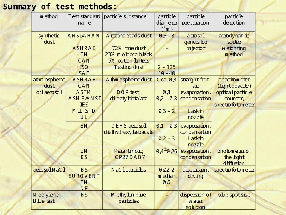
Summary of test methods:method Test standard
name particle substance particle
diameter (m)
particle preparation
particle detection
ANSI/AHAM
Arizona roads dust 0,5 - 3 aerosol generator
aerodynamic sorter
ASHRAE EN
CAN
72% fine dust 23% molocco black
5% cotton linters
-
synthetic dust
ISO SAE
Testing dust 2 – 125 10 - 40
injector
weighting method
athmospheric dust
ASHRAE CAN
Athmospheric dust Cca. 0,3 straight from air
opacitometer (light opacity)
0,3 0,2 – 0,3
evaporation, condensation
ASTM ASME/ANSI
IES MIL-STD
UL
DOP test; di-octylphtalate
0,3 – 2 Laskin nozzle
0,1 – 0,3 evaporation, condensation
EN DEHS aerosol diethylhexylsebacate
0,2 – 3
Laskin nozzle
optical particle counter,
spectrofotometer
oil aerosol
EN BS
Paraffin oil; CP27 DAB7
0,40,26 evaporation, condensation
photometer of the light diffusion
aerosol NaCl BS EUROVENT
EN NF
NaCl particles 0,02-2 median
0,6
dispersion, drying
spectrofotometer
Methylene Blue test
BS
Methylen blue particles
- dispersion of water
solution
blue spot size
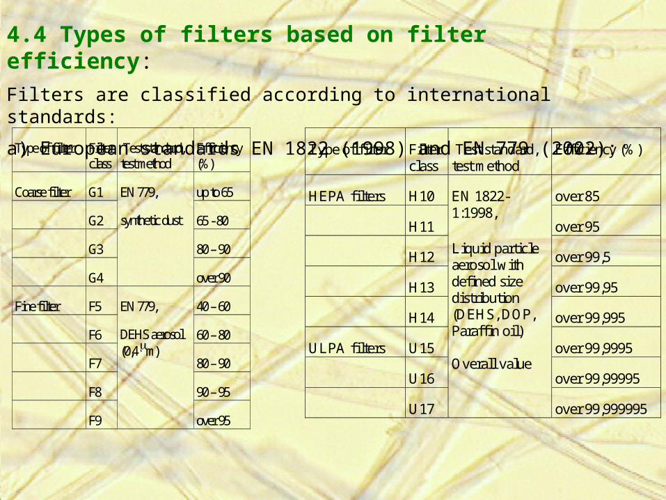
4.4 Types of filters based on filter efficiency:
Filters are classified according to international standards:
a) European standards EN 1822 (1998) and EN 779 (2002):
Type of filter Filter class
Test standard, test method
Efficiency (%)
Coarse filter G1 up to 65
G2 65 - 80
G3 80 – 90
G4
EN 779,
synthetic dust
over 90
Fine filter F5 40 – 60
F6 60 – 80
F7 80 – 90
F8 90 – 95
F9
EN 779,
DEHS aerosol (0,4 m)
over 95
Type of filter Filter class
Test standard, test method
Efficiency (%)
HEPA filters H10 over 85
H11 over 95
H12 over 99,5
H13 over 99,95
H14 over 99,995
ULPA filters U15 over 99,9995
U16 over 99,99995
U17
EN 1822-1:1998,
Liquid particle aerosol with defined size distribution (DEHS, DOP, Paraffin oil) Overall value
over 99,999995

Applications of filters according to EN 779 and EN 1822 standards.
Filter class Captured particles End use
G1
G2
Insects, fibers, coarse ash, particles with diameter around 1 mm
Coars pre-filters
G3
G4
Pollen, fibers, dust, fog... Pre-filters for heavy poluted air, painting boxes, home climatisation, kitchen digesters....
F5
F6
Pollen, fine dust, spores, partly bacteria Air ventilation of restaurants, workshops, storages, home, pre-filters for F9 class filters, heat exchangers
F7 Carbon black, bacteria, partly smoke and soot
End filters for shops, workrooms, homes etc... Pre-filters for H11 –H12class
F8
F9
Oil smoke, partly metal oxide smoke and tobacco smoke
End filters for laboratories, workshops etc... Pre filters for active carbon filters and H13 – H14 class (surgery, pharmacy
H10
H11
Every aerosols, partly tobacco smoke End filters for nuclear power plants, optical laboratories, light industry, hospitals etc...
H12
H13
Every viruses, radioactive aerosol End filters for hospitals with higher requirements,for public protection equipments, for food, electronic, pharmacy and foil industry
H14 Aerosol microparticles End filters for hospitals and biotechnology laboratories with higher requirements and strong rules for leakage test
U15 - U17 Aerosol microparticles Filters for clean areas ISO 1 -3

b) American standard ASHRAE 52.2 (1999)
Coarse filters (MERV 1 – 4) are tested by synthetic dust, other filters are tested by pottasium chloride particles with defined size (0,3 - 10 m) divided onto three ranges.
Composite Average Particle Size Efficiency in size range (%)
MERV (Minimum Efficiency Reporting value)
Range 1 0,30 – 1 m
Range 2 1 – 3 m
Range 3 3 – 10 m
Average Arrestance (%)
Minimum Final Resistance (Pa)
1 E3 < 20 Aavg< 65 75 2 E3 < 20 65< Aavg< 70 75 3 E3 < 20 70< Aavg< 75 75 4 E3 < 20 75< Aavg 75 5 20 E3 < 35 150 6 35 E3 < 50 150 7 50 E3 < 70 150 8 70 E3 150 9 E2 < 50 85 E3 250 10 50 E2 < 65 85 E3 250 11 65 E2 < 80 85 E3 250 12 80 E2 90 E3 250 13 E1 < 75 90 E2 90 E3 350 14 75 E1 < 85 90 E2 90 E3 350 15 85 E1 < 95 90 E2 90 E3 350 16 95 E1 95 E2 95 E3 350

Minimum Efficiency Reporting Value (MERV)
Captured particles End use
1 – 4 Pollen, dust mites, sanding dust, spray paint dust, textile fibers...
Pre-filters, window air conditioners...
5 – 8 Mold, spores, cement dust, snuff,...
Commercial buildings, residential, industrial workplaces, spray paint boxes...
9 – 12 Legionella, humidifier dust, lead dust, milled flour, coal dust, nebulizer drops, auto emissions...
Superior residental, better commercial buildings, hospital laboratories...
13 – 16 All bacteria, most tobacco smoke, most paint pigments, sneeze...
Hospital inpatient care, general surgery, superior commercial buildings...
17 - 20 Viruses, carbon dust, sea salt, smoke...
Cleanrooms, pharmaceutical manufacturing, carciogenic and radioactive materials...
Applications of filters according to ASHRAE 52.2 standard.

3. Types of filters based on its shape:

A) Flat filters:
Description and examples:
Flat filters are used without frame or (for bigger size) holded by rigid frame or supporting grid. They would be divided onto two variants. Bulk filters are: thermal or chemical bonded nonwovens, needle punch etc... Thin filters are:woven and knitted fabrics, spunbond, meltblown etc....
End use:
Cheap filters for common applications (vacuum cleaners, kitchen digestor, paint boxes, cabine filters in cars...) , pre-filters for most of air ventilation systems.
a) bulk filter b) thin filter
Polluted air
Clean air
Filter Supporting grid

B) Pleated filters
Description :
It is suitable fo high efficient filters. Pleating process leads to bigger filter surface and consequently to smaller pressure drop. It is possible to pleat flat materials, which stiffness and elongation is similar to paper (for example wet-laid nonvoven from glassfibers). It is necessary to hold textile pleats by rigid frame. Filter thickness is usually from 1 to 5 cm.
End use:
Pre-filters, HEPA filters (High Efficiency Particulate Arrestance) used in air ventilation and air condition systems, Auto cabin air filters, industrial applications, respirators for halfmasks etc...
Polluted air
Clean air
Rigid frame
Filter
Air flow direction
Filter thickness

Examples of pleated filters:
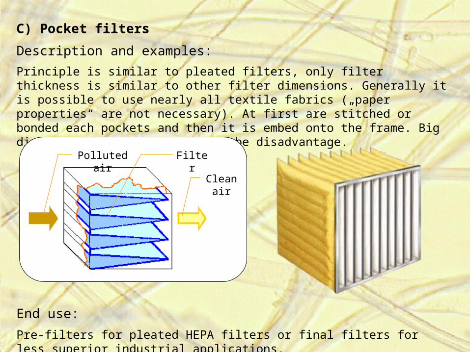
C) Pocket filters
Description and examples:
Principle is similar to pleated filters, only filter thickness is similar to other filter dimensions. Generally it is possible to use nearly all textile fabrics („paper properties“ are not necessary). At first are stitched or bonded each pockets and then it is embed onto the frame. Big dimension of this filter would be disadvantage.
End use: Pre-filters for pleated HEPA filters or final filters for less superior industrial applications.
Polluted air
Clean air
Filter

D) Cartridge filters
Description and examples:
Flat (bulky) filter or pleated filter is wrapped around the perfored tube. The advantage is smaler dimension of filter with regard to acting surface.
End use:
Most of filters inside the car, industrial applications etc... Very ofter used for liquid filtration.
Container
Variants of cartridge filter cross-section
Flat (bulky) filter Pleated filterFilter
Perforated tube
Polluted air
Clean air

Examples of cartridge filters
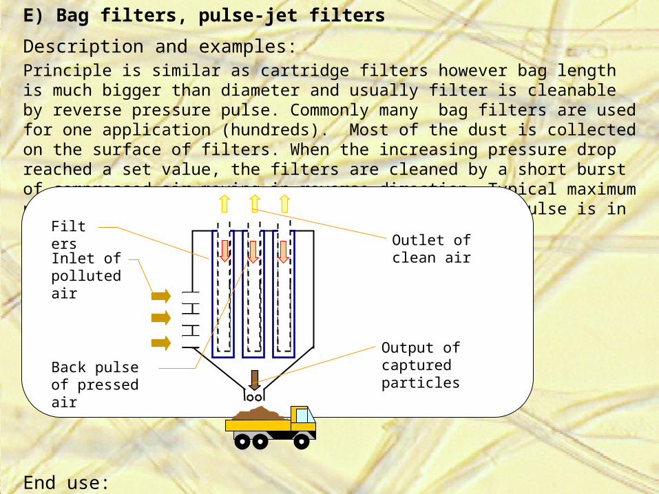
E) Bag filters, pulse-jet filters
Description and examples:Principle is similar as cartridge filters however bag length is much bigger than diameter and usually filter is cleanable by reverse pressure pulse. Commonly many bag filters are used for one application (hundreds). Most of the dust is collected on the surface of filters. When the increasing pressure drop reached a set value, the filters are cleaned by a short burst of compressed air moving in reverse direction. Typical maximum pressure drop is 1000 – 2000 Pa, typical pressure pulse is in range 0,5 – 1 MPa and cleanig time 0,1 - 100 sec.
End use:Industrial applications: chemical processings, cement fabric, incineration, power generation etc...
Inlet of polluted air
Filters
Back pulse of pressed air
Output of captured particles
Outlet of clean air

Examples of pulse-jet filters
Steel frames
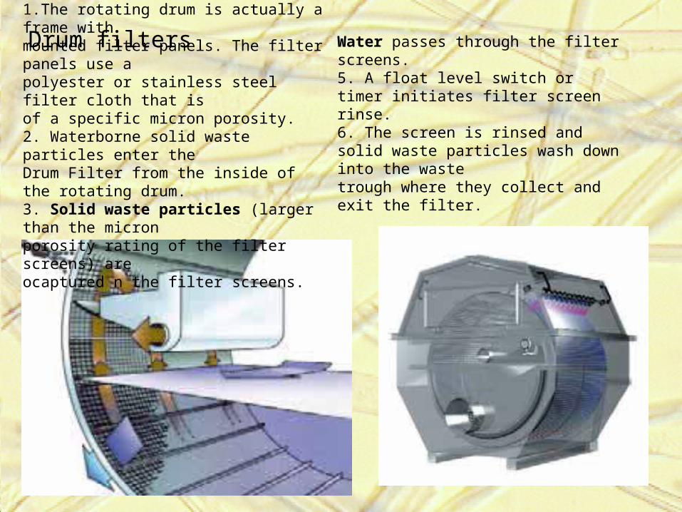
Drum filters1.The rotating drum is actually a frame withmounted filter panels. The filter panels use apolyester or stainless steel filter cloth that isof a specific micron porosity.2. Waterborne solid waste particles enter theDrum Filter from the inside of the rotating drum.3. Solid waste particles (larger than the micronporosity rating of the filter screens) areocaptured n the filter screens.
Water passes through the filter screens.5. A float level switch or timer initiates filter screen rinse.6. The screen is rinsed and solid waste particles wash down into the wastetrough where they collect and exit the filter.

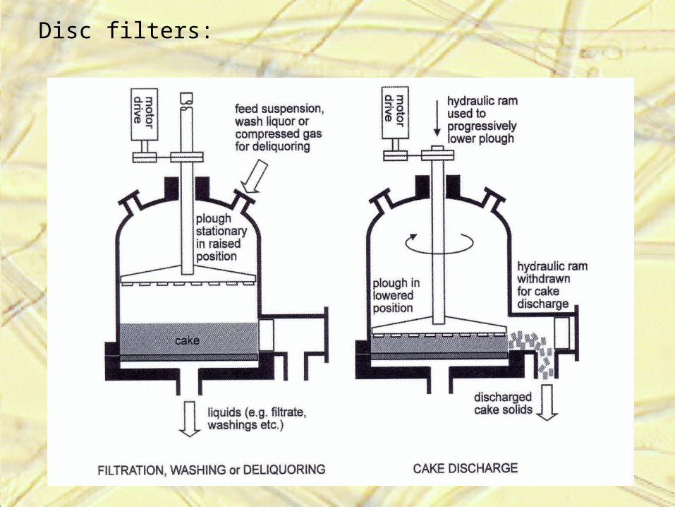
Disc filters:
