filmtec - die-faehre.de · the following cleaning procedure is designed specifically for a system...
TRANSCRIPT


Form No. 609-00300-402XQRPCH 172-250-E-402R
The following cleaning procedure is designed specifically for a system that has been fouled with biological matter. Consultthe general cleaning instructions for information that is common to all types of cleaning such as suggested equipment, pHand temperature limits, and recommended flow rates.
Safety Precautions1. When using any chemical indicated here in subsequent sections, follow accepted safety practices. Consult the
chemical manufacturer for detailed information about safety, handling and disposal.
2. When preparing cleaning solutions, ensure that all chemicals are dissolved and well mixed before circulating thesolutions through the elements.
3. It is recommended the elements be flushed with good-quality chlorine-free water (20°C minimum temperature) aftercleaning. Permeate water is recommended; but a dechlorinated potable supply or pre-filtered feedwater may be used,provided that there are no corrosion problems in the piping system. Care should be taken to operate initially at reducedflow and pressure to flush the bulk of the cleaning solution from the elements before resuming normal operatingpressures and flows. Despite this precaution, cleaning chemicals will be present on the permeate side followingcleaning. Therefore, permeate must be diverted to drain for at least 10 minutes or until the water is clear when startingup after cleaning.
4. During recirculation of cleaning solutions, the temperatures must not exceed 50°C at pH 2-10, 35°C at pH 1-11, and30°C at pH 1-12.
5. For elements greater than six inches in diameter, the flow direction during cleaning must be the same as during normaloperation to prevent element telescoping, because the vessel thrust ring is installed only on the reject end of thevessel. This is also recommended for smaller elements.
Cleaning ProcedureThere are seven steps in cleaning elements with biofouling.
1. Make up the cleaning solution listed from Table 1.
Table 1. Biofouling Cleaning SolutionsCleaning Solutions Solution
Preferred 0.1% (wt) NaOHpH 12, 30°C maximum
Preferred 0.1% (wt) NaOH0.025% (wt) Na-DSSpH 12, 30°C maximum
Alternate 0.1% (wt) NaOH1.0% (wt) Na4EDTApH 12, 30°C maximum
Notes1 (wt) denotes weight percent of active ingredient.2 Cleaning chemical symbols in order used: NaOH is sodium hydroxide; Na-DSS is sodium salt of dodecylsulfate; Sodium Laurel Sulfate;
Na4EDTA is the tetra-sodium salt of ethylene diamine tetraacetic acid and is available from The Dow Chemical Company under the trademarkVERSENE*.
FILMTEC Membranes
Tech Facts
*Trademark of The Dow Chemical Company
FILMTECTM Membranes
Cleaning Biofouling from FILMTEC FT30 Elements
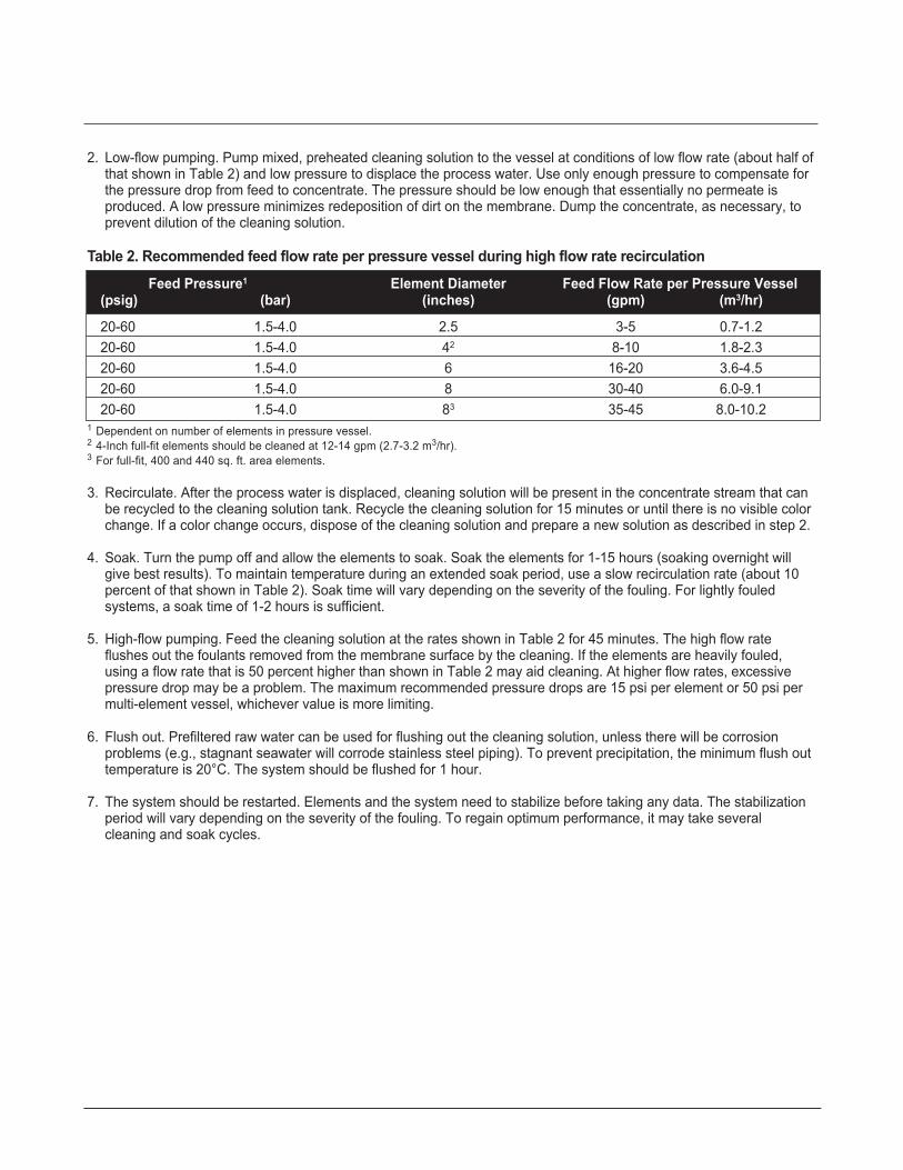
2. Low-flow pumping. Pump mixed, preheated cleaning solution to the vessel at conditions of low flow rate (about half ofthat shown in Table 2) and low pressure to displace the process water. Use only enough pressure to compensate forthe pressure drop from feed to concentrate. The pressure should be low enough that essentially no permeate isproduced. A low pressure minimizes redeposition of dirt on the membrane. Dump the concentrate, as necessary, toprevent dilution of the cleaning solution.
Table 2. Recommended feed flow rate per pressure vessel during high flow rate recirculationFeed Pressure1 Element Diameter Feed Flow Rate per Pressure Vessel
(psig) (bar) (inches) (gpm) (m3/hr)
20-60 1.5-4.0 2.5 3-5 0.7-1.220-60 1.5-4.0 42 8-10 1.8-2.320-60 1.5-4.0 6 16-20 3.6-4.520-60 1.5-4.0 8 30-40 6.0-9.120-60 1.5-4.0 83 35-45 8.0-10.2
1 Dependent on number of elements in pressure vessel.2 4-Inch full-fit elements should be cleaned at 12-14 gpm (2.7-3.2 m3/hr).3 For full-fit, 400 and 440 sq. ft. area elements.
3. Recirculate. After the process water is displaced, cleaning solution will be present in the concentrate stream that canbe recycled to the cleaning solution tank. Recycle the cleaning solution for 15 minutes or until there is no visible colorchange. If a color change occurs, dispose of the cleaning solution and prepare a new solution as described in step 2.
4. Soak. Turn the pump off and allow the elements to soak. Soak the elements for 1-15 hours (soaking overnight willgive best results). To maintain temperature during an extended soak period, use a slow recirculation rate (about 10percent of that shown in Table 2). Soak time will vary depending on the severity of the fouling. For lightly fouledsystems, a soak time of 1-2 hours is sufficient.
5. High-flow pumping. Feed the cleaning solution at the rates shown in Table 2 for 45 minutes. The high flow rateflushes out the foulants removed from the membrane surface by the cleaning. If the elements are heavily fouled,using a flow rate that is 50 percent higher than shown in Table 2 may aid cleaning. At higher flow rates, excessivepressure drop may be a problem. The maximum recommended pressure drops are 15 psi per element or 50 psi permulti-element vessel, whichever value is more limiting.
6. Flush out. Prefiltered raw water can be used for flushing out the cleaning solution, unless there will be corrosionproblems (e.g., stagnant seawater will corrode stainless steel piping). To prevent precipitation, the minimum flush outtemperature is 20°C. The system should be flushed for 1 hour.
7. The system should be restarted. Elements and the system need to stabilize before taking any data. The stabilizationperiod will vary depending on the severity of the fouling. To regain optimum performance, it may take severalcleaning and soak cycles.

*Trademark of The Dow Chemical Company
FILMTEC MembranesFor more information about FILMTEC membranes, call the Dow Liquid Separations business:North America . . . . . . . . . . .1-800-447-4369Latin America . . . . . . . . . . .(+55) 11-5188-9277Europe . . . . . . . . . . . . . . . .(+32) 3-450-2240Japan . . . . . . . . . . . . . . . . .(+81) 3-5460-2100Australia . . . . . . . . . . . . . . .(+61) 2-9776-3226http://www.filmtec.com
Form No. 609-00300-402XQRPCH 172-250-E-402R
NOTE: Recommendations made here are specifically designed for FILMTEC Reverse Osmosis and Nanofiltration elements. Theserecommendations, such as cleaning procedures and chemicals employed, may not be compatible with other brands of membrane elements. It isyour responsibility to ensure the suitability of our recommendations and procedures if they are applied to membrane elements other thanFilmTec products.
NOTICE: No freedom from any patent owned by Seller or others is to be inferred. Because use conditions and applicable laws may differ fromone location to another and may change with time, Customer is responsible for determining whether products and the information in thisdocument are appropriate for Customer’s use and for ensuring that Customer’s workplace and disposal practices are in compliance withapplicable laws and other governmental enactments. Seller assumes no obligation or liability for the information in this document. NOWARRANTIES ARE GIVEN; ALL IMPLIED WARRANTIES OF MERCHANTABILITY OR FITNESS FOR A PARTICULAR PURPOSE AREEXPRESSLY EXCLUDED.
Published April 2002.
Additional InformationBy experience, the cleaning solution of Na4EDTA with caustic has been found to be slightly less effective than a standardcaustic solution or a solution of caustic and Na-DSS.
For any solution, contact time is critical. Several overnight soaks may be necessary to restore the system performance.
After the elements are clean it is very beneficial to clean one additional time in order to clean off the last remainingbiofilm layer on the surface of the membrane. Any remaining biofilm will tend to attract and trap dirt, so an extra cleaningwill increase the time between cleanings.
For industrial systems where the permeate or product water is not used for drinking, a non-oxidizing biocide can be usedprior to step 1 of the cleaning procedure to kill any bacteria or biofilm in the system. Please refer to separate instructionson methods for sanitizing membrane systems (i.e., “Sanitization with DBNPA - Tech Facts”). If the only choice for asanitizing agent is an oxidant, such as hydrogen peroxide, the system must be cleaned before sanitization.

The following cleaning procedure is designed specifically for a system that has had carbonate scale precipitated in theelements. Consult the general cleaning instructions for information that is common to all types of cleaning such assuggested equipment, pH and temperature limits, and recommended flow rates.
Safety Precautions1. When using any chemical indicated here in subsequent sections, follow accepted safety practices. Consult the
chemical manufacturer for detailed information about safety, handling and disposal.
2. When preparing cleaning solutions, ensure that all chemicals are dissolved and well mixed before circulating thesolutions through the elements.
3. It is recommended the elements be flushed with good-quality chlorine-free water (20°C minimum temperature) aftercleaning. Permeate water is recommended; but a dechlorinated potable supply or prefiltered feedwater may be used,provided that there are no corrosion problems in the piping system. Care should be taken to operate initially at reducedflow and pressure to flush the bulk of the cleaning solution from the elements before resuming normal operatingpressures and flows. Despite this precaution, cleaning chemicals will be present on the permeate side followingcleaning. Therefore, permeate must be diverted to drain for at least 10 minutes or until the water is clear when startingup after cleaning.
4. During recirculation of cleaning solutions, the temperatures must not exceed 50°C at pH 2-10, 35°C at pH 1-11, and30°C at pH 1-12.
5. For elements greater than six inches in diameter, the flow direction during cleaning must be the same as during normaloperation to prevent element telescoping, because the vessel thrust ring is installed only on the reject end of thevessel. This is also recommended for smaller elements.
Cleaning ProcedureThere are seven steps in cleaning elements with carbonate scale.
1. Make up the cleaning solution listed from Table 1.
Table 1. Carbonate Scale Cleaning SolutionsCleaning Solutions Solution
Preferred 0.2% (wt) HClpH 2, 45°C maximum
Alternative 2.0% (wt) Citric Acid
FILMTEC Membranes
Tech Facts
*Trademark of The Dow Chemical Company
FILMTECTM Membranes
Cleaning Carbonate Scale from FILMTEC FT30 Elements
Notes1 (wt) denotes weight percent of active ingredient.2 Cleaning chemical symbols in order used: HCI is hydrochloric acid (Muriatic Acid).
Alternative 1.0% Na2S2O4
Alternative 0.5% H3PO4
Form No. 609-00301-1202XQRP

2. Low-flow pumping. Pump mixed, preheated cleaning solution to the vessel at conditions of low flow rate (about halfof that shown in Table 2) and low pressure to displace the process water. Use only enough pressure to compensatefor the pressure drop from feed to concentrate. The pressure should be low enough that essentially no permeate isproduced. A low pressure minimizes redeposition of dirt on the membrane. Dump the concentrate, as necessary, toprevent dilution of the cleaning solution.
Table 2. Recommended feed flow rate per pressure vessel during high flow rate recirculationFeed Pressure1 Element Diameter Feed Flow Rate per Pressure Vessel
(psig) (bar) (inches) (gpm) (m3/hr)
20-60 1.5-4.0 2.5 3-5 0.7-1.220-60 1.5-4.0 42 8-10 1.8-2.320-60 1.5-4.0 6 16-20 3.6-4.520-60 1.5-4.0 8 30-40 6.-9.120-60 1.5-4.0 83 35-45 8.0-10.2
1 Dependent on number of elements in pressure vessel.2 4-Inch full-fit elements should be cleaned at 12-14 gpm (2.7-3.2 m3/hr).3 For full-fit elements, 400 and 440 sq. ft. area elements.
3. Recirculate. After the process water is displaced, cleaning solution will be present in the concentrate stream that canbe recycled to the cleaning solution tank. Recycle the cleaning solution for 10 minutes or until there is no visible colorchange. If at anytime during the circulation process there is a change in pH or a color change, dispose of the solutionand prepare a new solution as described in step 2. A pH of 2 must be maintained for the cleaning to be effective.
4. Soak. Turn the pump off and allow the elements to soak. Soak the elements for 1-15 hours (soaking overnight willgive best results). To maintain temperature during an extended soak period, use a slow recirculation rate (about 10percent of that shown in Table 2). Soak time will vary depending on the severity of the scaling. For lightly scaledsystems, a soak time of 1-2 hours is sufficient.
5. High-flow pumping. Feed the cleaning solution at the rates shown in Table 2 for 10 minutes. The high flow rate flushesout the foulants removed from the membrane surface by the cleaning. If the elements are heavily fouled, using a flowrate that is 50 percent higher than shown in Table 2 may aid cleaning. At higher flow rates, excessive pressure dropmay be a problem. The maximum recommended pressure drops are 15 psi per element or 50 psi per multi-elementvessel, whichever value is more limiting.
6. Flush out. Prefiltered raw water can be used for flushing out the cleaning solution, unless there will be corrosionproblems (e.g., stagnant seawater will corrode stainless steel piping). To prevent precipitation, the minimum flush outtemperature is 20°C. The system should be flushed for one hour.
7. The system should be restarted. Elements and the system need to stabilize before taking any data. The stabilizationperiod will vary depending on the severity of the fouling. To regain optimum performance, it may take several cleaningand soak cycles.
*Trademark of The Dow Chemical Company
FILMTEC MembranesFor more information about FILMTEC membranes, call the Dow Liquid Separations business:North America . . . . . . . . . . .1-800-447-4369Latin America . . . . . . . . . . .(+55) 11-5188-9277Europe . . . . . . . . . . . . . . . .(+32) 3-450-2240Japan . . . . . . . . . . . . . . . . .(+81) 3-5460-2100Australia . . . . . . . . . . . . . . .(+61) 3-9226-3545http://www.filmtec.com
Form No. 609-00301-1202XQRP
NOTE: Recommendations made here are specifically designed for FILMTEC Reverse Osmosis and Nanofiltration elements. Theserecommendations, such as cleaning procedures and chemicals employed, may not be compatible with other brands of membrane elements. It isyour responsibility to ensure the suitability of our recommendations and procedures if they are applied to membrane elements other thanFilmTec products.
NOTICE: No freedom from any patent owned by Seller or others is to be inferred. Because use conditions and applicable laws may differ fromone location to another and may change with time, Customer is responsible for determining whether products and the information in thisdocument are appropriate for Customer’s use and for ensuring that Customer’s workplace and disposal practices are in compliance withapplicable laws and other governmental enactments. Seller assumes no obligation or liability for the information in this document. NOWARRANTIES ARE GIVEN; ALL IMPLIED WARRANTIES OF MERCHANTABILITY OR FITNESS FOR A PARTICULAR PURPOSE AREEXPRESSLY EXCLUDED.
Published December 2002.
Additional InformationNever recirculate the cleaning solution for longer than 20 minutes. With longer recirculation, the carbonate scale canreprecipitate and end up back on the membrane surface, making it more difficult to clean.
Carbonate scale reacts with HCl releasing carbon dioxide gas.
Depending on the severity of the fouling, it may take repeated cleanings to remove all the scale. Cleaning severe scalemay not be economical and element replacement may be the best choice.
Citric acid was originally used as a cleaner for cellulose acetate membranes and is not as effective with thin filmcomposite chemistry. Further, it has a disadvantage of being a nutrient source for systems, which have biological fouling.It is, however, easier to handle than HCl and is included as an alternative cleaner for that reason.

Colloidal Fouling Prevention
Tech Manual Excerpts
FILMTEC Membranes
*Trademark of The Dow Chemical Company
Figure 1: Apparatus for Measuring the Silt Density Index
TOGGLE or BALL VALE
PRESSURE REGULATOR
PRESSURE
GAUGE
FILTER HOLDER
IntroductionColloidal fouling of reverse osmosis elements can seriously impair performance by lowering productivity andsometimes salt rejection. An early sign of colloidal fouling is often an increased pressure differential across thesystem.
The source of silt or colloids in reverse osmosis feed waters is varied and often includes bacteria, clay, colloidalsilica and iron corrosion products. Pretreatment chemicals used in a clarifier such as alum, ferric chloride, orcationic polyelectrolytes can also cause colloidal fouling if not removed in the clarifier or through proper mediafiltration. In addition, cationic polymers may coprecipitate with negatively charged antiscalants and foul themembrane.
The best available technology for determining the colloidal fouling potential of reverse osmosis feed water is themeasurement of the Silt Density Index (SDI), sometimes referred to as the Fouling Index (FI). This is animportant measurement to be carried out prior to designing an RO pretreatment system and on a regular basisduring RO operation (three times a day is a recommended frequency for surface waters).
The Standard Test Method has been described in ASTM test D 4189-82.
Equipment(Available from Millipore Corporation)
• 47 mm diameter membrane filter support
• 47 mm diameter membrane filters (0.45 μm pore size)
• 1 to 5 bar (10-70 PSI) manometer
• needle valve for pressure adjustment
Figure 1 shows the equipment needed to measure SDI.
FILMTECTM Membranes Form No. 609-00307-702QRP
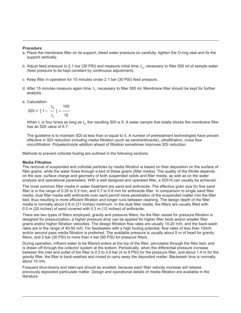
Procedurea. Place the membrane filter on its support, bleed water pressure on carefully, tighten the O-ring seal and fix the
support vertically.
b. Adjust feed pressure to 2.1 bar (30 PSI) and measure initial time, tO, necessary to filter 500 ml of sample water(feed pressure to be kept constant by continuous adjustment).
c. Keep filter in operation for 15 minutes under 2.1 bar (30 PSI) feed pressure.
d. After 15 minutes measure again time, t1, necessary to filter 500 ml. Membrane filter should be kept for furtheranalysis.
e. Calculation:tO 100
SDI = [ 1 – — ] x ——t1 15
When t1 is four times as long as t0, the resulting SDI is 5. A water sample that totally blocks the membrane filterhas an SDI value of 6.7.
The guideline is to maintain SDI at less than or equal to 5. A number of pretreatment technologies have proveneffective in SDI reduction including media filtration (such as sand/anthracite), ultrafiltration, cross flowmicrofiltration. Polyelectrolyte addition ahead of filtration sometimes improves SDI reduction.
Methods to prevent colloidal fouling are outlined in the following sections.
Media FiltrationThe removal of suspended and colloidal particles by media filtration is based on their deposition on the surface offilter grains, while the water flows through a bed of these grains (filter media). The quality of the filtrate dependson the size, surface charge and geometry of both suspended solids and filter media, as well as on the wateranalysis and operational parameters. With a well designed and operated filter, a SDI<5 can usually be achieved.The most common filter media in water treatment are sand and anthracite. The effective grain size for fine sandfilter is in the range of 0.35 to 0.5 mm, and 0.7 to 0.8 mm for anthracite filter. In comparison to single sand filtermedia, dual filter media with anthracite over sand permit more penetration of the suspended matter into the filterbed, thus resulting in more efficient filtration and longer runs between cleaning. The design depth of the filtermedia is normally about 0.8 m (31 inches) minimum. In the dual filter media, the filters are usually filled with0.5 m (20 inches) of sand covered with 0.3 m (12 inches) of anthracite.There are two types of filters employed, gravity and pressure filters. As the filter vessel for pressure filtration isdesigned for pressurization, a higher pressure drop can be applied for higher filter beds and/or smaller filtergrains and/or higher filtration velocities. The design filtration flow rates are usually 10-20 m/h, and the back-washrates are in the range of 40-50 m/h. For feedwaters with a high fouling potential, flow rates of less than 10m/hand/or second pass media filtration is preferred. The available pressure is usually about 5 m of head for gravityfilters, and 2 bar (30 PSI) to more than 4 bar (60 PSI) for pressure filters.During operation, influent water to be filtered enters at the top of the filter, percolates through the filter bed, andis drawn off through the collector system at the bottom. Periodically, when the differential pressure increasebetween the inlet and outlet of the filter is 0.3 to 0.6 bar (4 to 9 PSI) for the pressure filter, and about 1.4 m for thegravity filter, the filter is back-washed and rinsed to carry away the deposited matter. Backwash time is normallyabout 10 min.Frequent shut-downs and start-ups should be avoided, because each filter velocity increase will releasepreviously deposited particulate matter. Design and operational details of media filtration are available in theliterature.

Oxidation FiltrationSome well waters, usually brackish waters, are in a reduced state. Typical for these waters is the absence ofoxygen and the presence of divalent iron and manganese, sometimes also of hydrogen sulfide and ammonium.If such a water has been chlorinated and then dechlorinated, or has taken up more than 5 mg/l of oxygen, Fe2+
is converted into Fe3+, which forms insoluble colloidal hydroxide particles. The oxidation of iron and manganeseis given by:
4 Fe(HCO3)2 + O2 + 2H2O → 4 Fe(OH)3 + 8 CO2
4 Mn(HCO3)2 + O2 + 2H2O → 4 Mn(OH)3 + 8 CO2
Iron fouling occurs more frequently than manganese fouling, since the oxidation of iron occurs at a much lowerpH. Thus a fouling problem can be created even if the SDI is below 5, and the level of iron in the RO feed wateris below 0.1 mg/l. Waters with low alkalinity usually have higher iron concentrations than waters with highalkalinity, because the Fe2+ concentration is usually limited by the solubility of FeCO3.One method of handling such waters is to prevent the exposure to air or to any oxidizing agent, e.g. chlorine,through the whole RO process. A low pH is favorable to retard Fe2+ oxidation. At pH < 6 and oxygen < 0.5 mg/l,the maximum permissible Fe2+ concentration is 4 mg/l. The other way is to deliberately oxidize iron andmanganese by air, Cl2 or KMnO4. The formed hydroxides can then be removed by media filtration. Colloidalsulfur as formed from hydrogen sulfide however, may be difficult to remove. Oxidation and filtration can beaccomplished in one step by using a filter media with the ability to oxidize Fe2+ by electron transfer.Greensand is such a granular medium, which is a green (when dry) mineral glauconite. It can be regeneratedwith KMnO4 when its oxidizing capability is exhausted. After the regeneration, the residual KMnO4 has to bethoroughly rinsed out in order to avoid an oxidation damage of the membranes. This technique is used when< 2 mg/l Fe2+ is present in the raw water. For higher Fe2+ concentrations, KMnO4 can be continuously dosed intothe inlet stream of the filter. In this case however, measures have to be taken to assure that no permanganatecan reach the membranes, for example by installation of a carbon filter.Birm filtration has also been used effectively for Fe2+ removal from RO feed water. Since with birm a pH increaseand consequently a shift in the LSI value might occur, care should be taken to avoid CaCO3 precipitation in thefilter and in the RO system.
In-Line FiltrationThe efficiency of media filtration to reduce the SDI value can be markedly improved if the colloids in the rawwater are coagulated and/or flocculated prior to filtration. In-line filtration can be applied to raw waters with anSDI only slightly above 5. The method, also named in-line coagulation or in-line coagulation-flocculation, isdescribed in ASTM Standard D 4188. A coagulant is injected into the raw water stream, effectively mixed, andthe formed microflocs are immediately removed by media filtration.Ferric sulfate and ferric chloride are used to destabilize the negative surface charge of the colloids and to entrapthem into the freshly formed ferric hydroxide microflocs. Aluminium coagulants are also effective, but notrecommended because of possible fouling problems with residual aluminium.Rapid dispersion and mixing of the coagulant is extremely important. An in-line static mixer or injection on thesuction side of a booster pump is recommended. The optimum dosage is usually in the range of 10 to 30 mg/l,but should be determined case by case.To strengthen the hydroxide microflocs and thereby improving their filterability, and/or to bridge the colloidalparticles together, flocculants can be used in combination with coagulants or alone. Flocculants are soluble highmolecular mass organic compounds, e.g. linear polyacrylamides. Through different active groups, they may bepositively charged (cationic), negatively charged (anionic), or close to neutral (non-ionic).
Coagulants and flocculants may interfere with an RO membrane directly or indirectly. Indirect interference occurswhen the compound forms a precipitate which is deposited on the membrane. For example, channelling of themedia filter may enable flocs to pass through and deposit on the membrane. A precipitate can also be formedwhen concentrating the treated feedwater, such as when aluminium or ferric coagulants are added withoutsubsequently lowering pH to avoid supersaturation in the RO stage. Furthermore, reaction with a compound

added after the media filter can cause a precipitate to form. This is most noticeable with antiscalants. Nearly allantiscalants are negatively charged and will react with cationic coagulants or flocculants present in the water.Several RO plants have been heavily fouled by a gel formed by reaction between cationic polyelectrolytes andantiscalants.Direct interference occurs when the compound itself affects the membrane resulting in a flux loss. The ionicstrength of the water may have an effect on the interference of the coagulant or flocculant with the membrane.If so, the result at brackish water conditions could be different from that at sea water conditions. To minimise therisk of direct or indirect interference with the RO membrane, anionic or nonionic flocculants are preferred ratherthan cationic ones. Overdosing must be avoided.
Coagulation – FlocculationFor raw waters containing high concentrations of suspended matter resulting in a high SDI, the classiccoagulation – flocculation process is preferred. The hydroxide flocs are allowed to grow and to settle inspecifically designed reaction chambers. The hydroxide sludge is removed, and the supernatant water isfurther treated by media filtration.For the coagulation – flocculation process, either a solids-contact type clarifier or a compact coagulation –flocculation reactor may be used. For details, please refer to the general water treatment textbooks.
Crossflow Microfiltration/UltrafiltrationCrossflow filtration through a microfiltration (MF) or ultrafiltration (UF) membrane removes virtually all suspendedmatter and, in the case of ultrafiltration, also dissolved organic compounds depending on their molecular massand on the molecular mass cutoff of the membrane. Hence, an SDI < 1 can be achieved with a well designed andproperly maintained microfiltration or ultrafiltration system. The fouling problem, now transferred from the ROmembrane to the MF or UF membrane, has to be handled by this system. At the same time, a high MF/UFsystem recovery and a high specific permeate flow is requested for economic reasons. These objectives areusually achieved by periodic cleanings, either a forward flush or preferably a backflush. If a chlorine resistantmembrane material is used, e.g. polysulfone or a ceramic membrane, chlorine can be added to the wash waterin order to prevent biological fouling.
Cartridge MicrofiltrationA cartridge filter with a pore size of less than 10 μm is the minimum pretreatment required for every RO system.It is a safety device to protect the membranes and the high pressure pump from suspended particles. Usuallyit is the last step of a pretreatment sequence. We recommend to use a pore size of 5 μm or less. The better theprefiltration is, the less cleaning of the RO membranes is required. When the silica concentration in theconcentrate stream exceeds the theoretical solubility, cartridge filtration with 1 μm pore size is recommended inorder to minimise the interaction with iron and aluminium colloids.The filter should be sized on a flow rate according to the manufacturer’s recommendation, and replaced beforethe pressure drop has increased to the permitted limit, but at the latest, after three months. Backflushable filtersare not recommended because of their lower efficiency and higher biofouling risk.The cartridge filter should be made of a synthetic nondegradable material; e.g. nylon or polypropylene andequipped with a pressure gauge to indicate the differential pressure drop and thereby indicating the extent ofits fouling. Regular inspections of used cartridges provide useful information regarding fouling risks and cleaningrequirements. If the differential pressure across the filter increases rapidly, it is an indication of possible problemsin the raw water supply or in the pretreatment process. The filter provides some degree of short term protectionfor the membranes while corrective action is taking place.Replacing cartridge filters more often than every 1 to 3 months usually indicates a problem with the pretreatment.However, the cartridge filter is not meant to be a major component for the removal of high amounts of filterablesolids. This would not only be an inefficient use of rather expensive filters, but would probably lead to prematurefailure of the membrane system due to the high probability that some of the unwanted material will break through.It may be considered however, to use upstream a second cartridge with larger pore size.

The technical information contained here is extracted from the FILMTEC Membranes - Technical Manual. References to other sections of themanual have been replaced with short references to additional but separate information available from our web site. The information in theseextracts has been updated and supercedes that contained in the full manual.
Notice: No freedom from any patent owned by Seller or others is to be inferred. Because use conditions and applicable laws may differ from onelocation to another and may change with time, Customer is responsible for determining whether products and the information in this documentare appropriate for Customerís use and for ensuring that Customerís workplace and disposal practices are in compliance with applicablelaws and other governmental enactments. Seller assumes no obligation or liability for the information in this document. NO WARRANTIES AREGIVEN; ALL IMPLIED WARRANTIES OF MERCHANTABILITY OR FITNESS FOR A PARTICULAR PURPOSE ARE EXPRESSLY EXCLUDED.
Published July 2002.
FILMTEC MembranesFor more information about FILMTEC membranes,call Dow Liquid Separations business:North America ...................... 1-800-447-4369Latin America ....................... (+55) 11-5188-9277Europe ................................. (+32) 3-450-2240Japan ................................... (+81) 3-5460-2100Australia ............................... (+61) 2-9776-3226http://www.filmtec.com
*Trademark of The Dow Chemical CompanyForm No. 609-00307-702QRP
Other MethodsOther methods to prevent colloidal fouling than those described in the previous chapters also exist.Lime Softening is described in separate information on Scale Control as a method for silica removal. Removalof iron and colloidal matter are further benefits.Strong acid cation exchange resin softening does not only remove hardness, but also lowers concentrationsof iron and aluminium that otherwise could foul the membranes. Softened water is also known to exhibit a lowerfouling tendency than unsoftened water, because multivalent cations promote the adhesion of naturally occurringcolloids, which are usually negatively charged.Backflushable fine filters may be used upstream of the cartridge filters to protect these. They are, however,no substitute for disposable cartridges.
Design and Operational ConsiderationsThe prevention of colloidal fouling is not only a matter of the proper pretreatment technique, but also of thesystem design and operation. As an extreme example, a surface water could be pretreated by coagulation –flocculation and ultrafiltration. The RO system could then operate with a high permeate flux, and almost no cleaningwould be required. If the same water, however, would just be cartridge filtered, then the RO system would needmuch more membrane area, and the membranes would require frequent cleaning and maintenance. A poorpretreatment can be partially compensated by adding more membrane area and modifying the system, and bymore frequent and/or harsh cleaning. On the other hand, improving the pretreatment means savings inmembrane costs. In order to minimize the pretreatment effort and/or improve the feed water quality, the bestavailable raw water quality should be used. The intake of surface water, including sea water is of paramountimportance. A contamination of the raw water with waste water effluent may cause serious problems in theRO plant. A deep well close to the shore or the river is preferred. If an open intake is required, it should belocated well away from the shore and some meters below the water surface.New wells often release suspended matter in the first days of operation. Care must be taken that wells areproperly rinsed out.Fouling by iron oxide is also a common problem. It can be avoided by selecting non-corrosive materials.

Form No. 609-00302-402XQRPCH 172-252-E-402R
The following cleaning procedure is designed specifically for a system that is fouled with iron. Consult the generalcleaning instructions for information that is common to all types of cleaning such as suggested equipment, pH andtemperature limits, and recommended flow rates.
Safety Precautions1. When using any chemical indicated here in subsequent sections, follow accepted safety practices. Consult the
chemical manufacturer for detailed information about safety, handling and disposal.
2. When preparing cleaning solutions, ensure that all chemicals are dissolved and well mixed before circulating thesolutions through the elements.
3. It is recommended the elements be flushed with good-quality chlorine-free water (20°C minimum temperature) aftercleaning. Permeate water is recommended; but a dechlorinated potable supply or prefiltered feedwater may be used,provided that there are no corrosion problems in the piping system. Care should be taken to operate initially at reducedflow and pressure to flush the bulk of the cleaning solution from the elements before resuming normal operatingpressures and flows. Despite this precaution, cleaning chemicals will be present on the permeate side followingcleaning. Therefore, permeate must be diverted to drain for at least 10 minutes or until the water is clear when startingup after cleaning.
4. During recirculation of cleaning solutions, the temperatures must not exceed 50°C at pH 2-10, 35°C at pH 1-11, and30°C at pH 1-12.
5. For elements greater than six inches in diameter, the flow direction during cleaning must be the same as during normaloperation to prevent element telescoping, because the vessel thrust ring is installed only on the reject end of thevessel. This is also recommended for smaller elements.
Cleaning ProcedureThere are seven steps in cleaning elements with iron fouling.
1. Make up the cleaning solution listed from Table 1.
Table 1. Iron Fouling Cleaning SolutionsCleaning Solutions Solution
Preferred 1.0% (W) Na2S2O4
pH 5, 30°C max.
Alternative 2.0% (wt) Citric Acid
FILMTEC Membranes
Tech Facts
*Trademark of The Dow Chemical Company
FILMTECTM Membranes
Cleaning Iron Fouling from FILMTEC FT30 Elements
Notes1 (wt) denotes weight percent of active ingredient.2 Cleaning chemical symbols in order used: Na2S2O4 is sodium hydrosulfite.
Preferred 0.5% H3PO4
Alternative 1.0% NH2SO4H

2. Low-flow pumping. Pump mixed, preheated cleaning solution to the vessel at conditions of low flow rate (about half ofthat shown in Table 2) and low pressure to displace the process water. Use only enough pressure to compensate forthe pressure drop from feed to concentrate. The pressure should be low enough that essentially no permeate isproduced. A low pressure minimizes redeposition of dirt on the membrane. Dump the concentrate, as necessary, toprevent dilution of the cleaning solution.
Table 2. Recommended feed flow rate per pressure vessel during high flow rate recirculationFeed Pressure1 Element Diameter Feed Flow Rate per Pressure Vessel
(psig) (bar) (inches) (gpm) (m3/hr)
20-60 1.5-4.0 2.5 3-5 0.7-1.220-60 1.5-4.0 42 8-10 1.8-2.320-60 1.5-4.0 6 16-20 3.6-4.520-60 1.5-4.0 8 30-40 6.-9.120-60 1.5-4.0 83 35-45 8.0-10.2
1 Dependent on number of elements in pressure vessel.2 4-Inch full-fit elements should be cleaned at 12-14 gpm (2.7-3.2 m3/hr).3 For full-fit elements, 400 and 440 sq. ft. area elements.
3. Recirculate. After the process water is displaced, cleaning solution will be present in the concentrate stream that canbe recycled to the cleaning solution tank. Recycle the cleaning solution for 15 minutes or until there is no visible colorchange. If at anytime during the circulation process there is a color change, dispose of the solution and prepare anew solution as described in step 2.
4. Soak. Turn the pump off and allow the elements to soak. Soak the elements for 1-15 hours to remove the iron fromthe surface of the membrane (soaking overnight will give best results). Soak times are essential for the sodiumhydrosulfite to be effective. To maintain temperature during an extended soak period, use a slow recirculation rate(about 10 percent of that shown in Table 2). Soak time will vary depending on the severity of the fouling. For lightlyfouled systems, a soak time of 1-2 hours is sufficient.
5. High-flow pumping. Feed the cleaning solution at the rates shown in Table 2 for 45 minutes. The high flow rateflushes out the iron removed from the membrane surface by the cleaning. If the elements are heavily fouled, using aflow rate that is 50 percent higher than shown in Table 2 may aid cleaning. At higher flow rates, excessive pressuredrop may be a problem. The maximum recommended pressure drops are 15 psi per element or 50 psi per multi-element vessel, whichever value is more limiting. If there is a color change, dispose of the solution and prepare anew solution as described in step 2 and repeat the process from step 3.
6. Flush out. Prefiltered raw water can be used for flushing out the cleaning solution, unless there will be corrosionproblems (e.g., stagnant seawater will corrode stainless steel piping). The system should be flushed for one hour.
7. The system should be restarted. Elements and the system need to stabilize before taking any data. The stabilizationperiod will vary depending on the severity of the fouling. To regain optimum performance, it may take severalcleaning and soak cycles.

*Trademark of The Dow Chemical Company
FILMTEC MembranesFor more information about FILMTEC membranes, call the Dow Liquid Separations business:North America . . . . . . . . . . .1-800-447-4369Latin America . . . . . . . . . . .(+55) 11-5188-9277Europe . . . . . . . . . . . . . . . .(+32) 3-450-2240Japan . . . . . . . . . . . . . . . . .(+81) 3-5460-2100Australia . . . . . . . . . . . . . . .(+61) 2-9776-3226http://www.filmtec.com
Form No. 609-00302-402XQRPCH 172-252-E-402R
NOTE: Recommendations made here are specifically designed for FILMTEC Reverse Osmosis and Nanofiltration elements. Theserecommendations, such as cleaning procedures and chemicals employed, may not be compatible with other brands of membrane elements. It isyour responsibility to ensure the suitability of our recommendations and procedures if they are applied to membrane elements other thanFilmTec products.
NOTICE: No freedom from any patent owned by Seller or others is to be inferred. Because use conditions and applicable laws may differ fromone location to another and may change with time, Customer is responsible for determining whether products and the information in thisdocument are appropriate for Customer’s use and for ensuring that Customer’s workplace and disposal practices are in compliance withapplicable laws and other governmental enactments. Seller assumes no obligation or liability for the information in this document. NOWARRANTIES ARE GIVEN; ALL IMPLIED WARRANTIES OF MERCHANTABILITY OR FITNESS FOR A PARTICULAR PURPOSE AREEXPRESSLY EXCLUDED.
Published April 2002.
Additional InformationThe sodium hydrosulfite has a very pungent odor, so the room must be well ventilated. Follow all safety regulations andprocedures.
Contact time is key to successful cleaning. The solution will sometimes change many different colors. Black, brown,yellow are all very normal for this type of cleaning. Anytime the solution changes color, it should be disposed of and anew solution prepared. The length of time and the number of soaking periods will depend on the severity of the fouling.
Citric acid was originally used as a cleaner for cellulose acetate membranes and is not as effective with thin filmcomposite chemistry. Further, it has a disadvantage of being a nutrient source for systems, which have biological fouling.It is, however, easier to handle than sodium hydrosulfite and is included as an alternative cleaner for that reason.
The following cleaning procedure is designed specifically for a system that has been fouled with organic species such ashumic and fulvic acids, antiscalants, or oils. Consult the general cleaning instructions for information that is common to alltypes of cleaning such as suggested equipment, pH and temperature limits, and recommended flow rates.
Safety Precautions1. When using any chemical indicated here in subsequent sections, follow accepted safety practices. Consult the
chemical manufacturer for detailed information about safety, handling and disposal.
2. When preparing cleaning solutions, ensure that all chemicals are dissolved and well mixed before circulating thesolutions through the elements.
3. It is recommended the elements be flushed with good-quality chlorine-free water (20°C minimum temperature) aftercleaning. Permeate water is recommended; but a dechlorinated potable supply or prefiltered feedwater may be used,provided that there are no corrosion problems in the piping system. Care should be taken to operate initially at reducedflow and pressure to flush the bulk of the cleaning solution from the elements before resuming normal operatingpressures and flows. Despite this precaution, cleaning chemicals will be present on the permeate side followingcleaning. Therefore, permeate must be diverted to drain for at least 10 minutes or until the water is clear when startingup after cleaning.
4. During recirculation of cleaning solutions, the temperatures must not exceed 50°C at pH 2-10, 35°C at pH 1-11, and30°C at pH 1-12.
5. For elements greater than six inches in diameter, the flow direction during cleaning must be the same as during normaloperation to prevent element telescoping, because the vessel thrust ring is installed only on the reject end of thevessel. This is also recommended for smaller elements.
Cleaning ProcedureThere are six steps in cleaning elements fouled with organics, but the six steps are repeated once with a high pHcleaning solution and once with a low pH cleaning solution.
1. Make up the desired high pH cleaning solution selected from Table 1.
2. Low-flow pumping. Pump mixed, preheated cleaning solution to the vessel at conditions of low flow rate (about half ofthat shown in Table 2) and low pressure to displace the process water. Use only enough pressure to compensate forthe pressure drop from feed to concentrate. The pressure should be low enough that essentially no permeate isproduced. A low pressure minimizes redeposition of dirt on the membrane. Dump the concentrate, as necessary, toprevent dilution of the cleaning solution.
FILMTEC Membranes
Tech Facts
*Trademark of The Dow Chemical Company
FILMTECTM Membranes
Cleaning Organic Fouling from FILMTEC FT30 Elements
Form No. 609-00303-1202XQRP

Table 1. Organic Fouling Cleaning SolutionsCleaning Solutions Solution
Preferred 0.1% (wt) NaOHpH 12, 30°C maximum, followed by0.2% HClpH 2, 45°C maximum
Preferred 0.1% (wt) NaOH0.025% (wt) Na-DSSpH 12, 30°C maximum, followed by0.2% HClpH 2, 45°C maximum
Alternate 0.1% (wt) NaOH1.0% (wt) Na4EDTApH 12, 30°C maximum, followed by0.2% HClpH 2, 45°C maximum
Notes1 (wt) denotes weight percent of active ingredient.2 Cleaning chemical symbols in order used: NaOH is sodium hydroxide; HCI is
hydrochloric acid (Muratic Acid); Na-DSS is sodium salt of dodecylsulfate; Sodium LaurelSulfate; Na4EDTA is the tetra-sodium salt of ethylene diamine tetraacetic acid and isavailable from The Dow Chemical Company under the trademark VERSENE*.
Table 2. Recommended feed flow rate per pressure vessel during high flow rate recirculationFeed Pressure1 Element Diameter Feed Flow Rate per Pressure Vessel
(psig) (bar) (inches) (gpm) (m3/hr)
20-60 1.5-4.0 2.5 3-5 0.7-1.220-60 1.5-4.0 42 8-10 1.8-2.320-60 1.5-4.0 6 16-20 3.6-4.520-60 1.5-4.0 8 30-40 6.-9.120-60 1.5-4.0 83 35-45 8.0-10.2
1 Dependent on number of elements in pressure vessel.2 4-Inch full-fit elements should be cleaned at 12-14 gpm (2.7-3.2 m3/hr).3 For full-fit elements, 400 and 440 sq. ft. area elements.
3. Recirculate. After the process water is displaced, cleaning solution will be present in the concentrate stream that can be recycled to the cleaning solution tank. Recycle the cleaning solution for 30 minutes. If a color change occurs, dispose of the cleaning solution and prepare a new solution as described in step 2.
4. Soak. Turn the pump off and allow the elements to soak. Soak the elements for 1-15 hours (soaking overnight willgive best results). To maintain temperature during an extended soak period, use a slow recirculation rate (about 10percent of that shown in Table 2). Soak time will vary depending on the severity of the fouling. For lightly fouledsystems, a soak time of 1-2 hours is sufficient.

*Trademark of The Dow Chemical Company
FILMTEC MembranesFor more information about FILMTEC membranes, call the Dow Liquid Separations business:North America . . . . . . . . . . .1-800-447-4369Latin America . . . . . . . . . . .(+55) 11-5188-9277Europe . . . . . . . . . . . . . . . .(+32) 3-450-2240Japan . . . . . . . . . . . . . . . . .(+81) 3-5460-2100Australia . . . . . . . . . . . . . . .(+61) 3-9226-3545http://www.filmtec.com
Form No. 609-00303-1202XQRP
NOTE: Recommendations made here are specifically designed for FILMTEC Reverse Osmosis and Nanofiltration elements. Theserecommendations, such as cleaning procedures and chemicals employed, may not be compatible with other brands of membrane elements. It isyour responsibility to ensure the suitability of our recommendations and procedures if they are applied to membrane elements other thanFilmTec products.
NOTICE: No freedom from any patent owned by Seller or others is to be inferred. Because use conditions and applicable laws may differ fromone location to another and may change with time, Customer is responsible for determining whether products and the information in thisdocument are appropriate for Customer’s use and for ensuring that Customer’s workplace and disposal practices are in compliance withapplicable laws and other governmental enactments. Seller assumes no obligation or liability for the information in this document. NOWARRANTIES ARE GIVEN; ALL IMPLIED WARRANTIES OF MERCHANTABILITY OR FITNESS FOR A PARTICULAR PURPOSE AREEXPRESSLY EXCLUDED.
Published December 2002.
5. High-flow pumping. Feed the cleaning solution at the rates shown in Table 2 for 30 minutes. The high flow rate flushesout the foulants removed from the membrane surface by the cleaning. If the elements are heavily fouled, using a flowrate that is 50 percent higher than shown in Table 2 may aid cleaning. At higher flow rates, excessive pressure dropmay be a problem. The maximum recommended pressure drops are 15 psi per element or 50 psi per multi-elementvessel, whichever value is more limiting.
6. Flush out. Prefiltered raw water can be used for flushing out the cleaning solution, unless there will be corrosionproblems (e.g., stagnant seawater will corrode stainless steel piping). The system should be flushed for one hourduring the final flush in preparation for restarting the system.
7. Repeat steps 2 through 6 with cleaning solution of HCl at pH 2.
8. The system should be restarted. Elements and the system need to stabilize before taking any data. The stabilizationperiod will vary depending on the severity of the fouling. To regain optimum performance, it may take several cleaningand soak cycles.
Additional InformationFor maximum effectiveness, temperature of the cleaning solutions must be above 25°C. Elevating the temperature of thecleaning solutions helps them to lift the organic from the membrane surface.
Some organics such as oils are very difficult to remove. To remove them, experiment with different soak times foroptimum effectiveness. In addition, the most effective cleaning solution usually contains a surfactant such as Na-DSS orperhaps some commercially available membrane cleaners containing surfactants or detergents that can help remove theoils. Consult your chemical supplier for their recommendation.
If the organic fouling is the result of overfeeding of a coagulant used for feed water pretreatment, reversing the order ofthe cleaners can be more effective. To determine the proper order of the cleaning solutions (high pH followed by low pHor vice versa), try to gather a sample of the organic foulant from your system. With the sample, try treating it with causticand then acid and vice versa to determine qualitatively which order of cleaning solution treatment dissolves the foulantbetter. If both treatments appear to work equal, it is usually better to clean with the high pH solution first.

The following are general recommendations for cleaning FILMTECTM FT30 elements. More detailed procedures forcleaning an RO system are typically included in the operating manual provided by the system supplier. It should beemphasized that frequent cleaning is not required for a properly designed and properly operated RO system, howeverbecause of the FT30 membrane’s unique combination of pH range and temperature resistance, cleaning can beaccomplished very effectively.
Cleaning RequirementsIn normal operation, the membrane in reverse osmosis elements can become fouled by mineral scale, biological matter,colloidal particles, and insoluble organic constituents. Deposits build up on the membrane surfaces during operation untilthey cause loss in normalized permeate flow, loss of normalized salt rejection, or both. Elements should be cleanedwhenever the normalized permeate flow drops by ≥10 percent, or the normalized salt passage increases by ≥5 percent,or the normalized differential pressure (feed pressure minus concentrate pressure) increases by ≥15 percent from thereference condition established during the first 48 hours of operation.
Differential Pressure (ΔP) should be measured and recorded across each stage of the array of pressure vessels. If thebrine channels within the element become plugged, the ΔP will increase. It should be noted that the permeate flux willdrop if feedwater temperature decreases. This is normal and does not indicate membrane fouling.
A malfunction in the pretreatment, pressure control, or increase in recovery can result in reduced product water output oran increase in salt passage. If a problem is observed, these causes should be considered first. The element(s) may notrequire cleaning. A computer program called FTNORM is available from FilmTec for normalizing performance data ofFILMTEC RO membranes. This program can be used to assist in determining when to clean and can be downloadedfrom our web site.
Safety Precautions1. When using any chemical indicated here in subsequent sections, follow accepted safety practices. Consult the
chemical manufacturer for detailed information about safety, handling and disposal.
2. When preparing cleaning solutions, ensure that all chemicals are dissolved and well mixed before circulating thesolutions through the elements.
3. It is recommended the elements be flushed with good-quality chlorine-free water (20°C minimum temperature) aftercleaning. Permeate water is recommended; but a dechlorinated potable supply or prefiltered feedwater may be used,provided that there are no corrosion problems in the piping system. Care should be taken to operate initially at reducedflow and pressure to flush the bulk of the cleaning solution from the elements before resuming normal operatingpressures and flows. Despite this precaution, cleaning chemicals will be present on the permeate side followingcleaning. Therefore, the permeate must be diverted to drain for at least 10 minutes or until the water is clear whenstarting up after cleaning.
FILMTEC Membranes
Tech Facts
*Trademark of The Dow Chemical Company
FILMTEC Membranes
Cleaning Procedures for FILMTEC FT30 Elements
Form No. 609-23010-1202XQRP

4. During recirculation of cleaning solutions, the temperatures must not exceed 50°C at pH 2-10, 35°C at pH 1-11, and30°C at pH 1-12.
5. For elements greater than six inches in diameter, the flow direction during cleaning must be the same as duringnormal operation to prevent element telescoping, because the vessel thrust ring is installed only on the reject end ofthe vessel. This is also recommended for smaller elements. Equipment for cleaning is illustrated below.
PermeateTo Cleaning Tank(Cleaning Operation)
ConcentrateTo Cleaning Tank(Cleaning Operation)
PermeateTo Storage Tank(Normal Operation)
ConcentrateTo Drain(Normal Operation)
PermeateFrom Storage Tank
Tank
V6
V5
TCTI LLS
PUMPSSCF
DP
FIFT PI
RO UNITV1
V2
V3V7
V4
IH
TANK Chemical Mixing Tank, polypropylene or FRPIH Immersion Heater (may be replaced by cooling
coil for some site locations)TI Temperature IndicatorTC Temperature ControlLLS Lower Level Switch to shut off pumpSS Security Screen–100 meshPUMP Low-Pressure Pump, 316 SS or
non-metallic compositeCF Cartridge Filter, 5-10 micron polypropylene with
PVC, FRP, or SS housing
DP Differential Pressure GaugeFI Flow IndicatorFT Flow Transmitter (optional)PI Pressure IndicatorV1 Pump Recirculation Valve, CPVCV2 Flow Control Valve, CPVCV3 Concentrate Valve, CPVC 3-way valveV4 Permeate Valve, CPVC 3-way valveV5 Permeate Inlet Valve, CPVCV6 Tank Drain Valve, PVC, or CPVCV7 Purge Valve, SS, PVC, or CPVC
Cleaning System Flow Diagram

Suggested EquipmentThe equipment for cleaning is shown in the Cleaning System Flow Diagram. The pH of cleaning solutions used withFILMTEC elements can be in the range of 1 to 12 (see Table 2), and therefore non-corroding materials should be used inthe cleaning system.
1. The mixing tank should be constructed of polypropylene or fiberglass-reinforced plastic (FRP). The tank should beprovided with a removable cover and a temperature gauge. The cleaning procedure is more effective when performedat a warm temperature, and it is recommended that the solution be maintained according to the pH and temperatureguidelines listed in Table 2. It is not recommended to use a cleaning temperature below 15°C because of the veryslow chemical kinetics at low temperatures. In addition, chemicals such as sodium lauryl sulfate might precipitate atlow temperatures. Cooling may also be required in certain geographic regions, so both heating/cooling requirementsmust be considered during the design. A rough rule of thumb in sizing a cleaning tank is to use approximately theempty pressure vessels volume and then add the volume of the feed and return hoses or pipes. For example, to cleanten 8-inch diameter pressure vessels with six elements per vessel, the following calculations would apply:
A. Volume in VesselsV1 = πr2L
= 3.14 (4 in)2 (20 ft) (7.48 gal/ft3) / (144 in2/ft2)V1 = 52 gal/vessel (0.2 m3)V10 = 52 x 10 = 520 gal (1.97 m3)
B. Volume in Pipes, assume 50 ft. length total 4" Sch 80 pipeVp = πr2L
= 3.14 (1.91 in)2 (50 ft) (7.48 gal/ft3) / (144 in2/ft2)= 30 gals (0.11 m3)
Vct = V10 + Vp = 520 + 30 = 550 gal.
Therefore, the cleaning tank should be about 700 gals (1.5 m3).
2. The cleaning pump should be sized for the flows and pressures given in Table 1, making allowances for pressure lossin the piping and across the cartridge filter. The pump should be constructed of 316 SS or nonmetallic compositepolyesters.
3. Appropriate valves, flow meters, and pressure gauges should be installed to adequately control the flow. Service linesmay be either hard piped or hoses. In either case, the flow rate should be a moderate 10 ft/sec (3 m/sec) or less.

Cleaning Elements In SituThere are six steps in the cleaning of elements:
1. Make up cleaning solution.
2. Low-flow pumping. Pump mixed, preheated cleaning solution to the vessel at conditions of low flow rate (about halfof that shown in Table 1) and low pressure to displace the process water. Use only enough pressure to compensatefor the pressure drop from feed to concentrate. The pressure should be low enough that essentially no permeate isproduced. A low pressure minimizes redeposition of dirt on the membrane. Dump the concentrate, as necessary, toprevent dilution of the cleaning solution.
3. Recycle. After the process water is displaced, cleaning solution will be present in the concentrate stream. Thenrecycle the concentrate to the cleaning solution tank and allow the temperature to stabilize.
Table 1. Recommended feed flow rate per pressure vessel during high flow rate recirculationFeed Pressure1 Element Diameter Feed Flow Rate per Pressure Vessel
(psig) (bar) (inches) (gpm) (m3/hr)
20-60 1.5-4.0 2.5 3-5 0.7-1.220-60 1.5-4.0 42 8-10 1.8-2.320-60 1.5-4.0 6 16-20 3.6-4.520-60 1.5-4.0 8 30-40 6.-9.120-60 1.5-4.0 83 35-45 8.0-10.2
1 Dependent on number of elements in pressure vessel.2 4-Inch Full-fit elements should be cleaned at 12-14 gpm (2.7-3.2 m3/hr).3 For Full-fit, 400 and 440 sq. ft. area elements.
Table 2. pH range and temperature limits during cleaning
Max Temp Max Temp Max Temp50°C 35°C 30°C Continuous
Element Type pH Range pH Range pH Range Operation
SW30, SW30HR 3-10 2-11 1-12 2-11BW30, TW30 2-10 1-11 1-12 2-11NF45, SR90 3-10 2-11 1-12 3-10NF70, NF90 3-10 2-11 1-11 3-9
4. Soak. Turn the pump off and allow the elements to soak. Sometimes a soak period of about 1 hour is sufficient.For difficult fouling an extended soak period is beneficial; soak the elements overnight for 10-15 hours. To maintaina high temperature during an extended soak period, use a slow recirculation rate (about 10 percent of that shownin Table 1).
5. High-flow pumping. Feed the cleaning solution at the rates shown in Table 1 for 30-60 minutes. The high flow rateflushes out the foulants removed from the membrane surface by the cleaning. If the elements are heavily fouled, aflow rate which is 50 percent higher than shown in Table 1 may aid cleaning. At higher flow rates, excessivepressure drop may be a problem. The maximum recommended pressure drops are 15 psi per element or 50 psi permulti-element vessel, whichever value is more limiting.

6. Flush out. Prefiltered raw water can be used for flushing out the cleaning solution, unless there will be corrosionproblems (e.g., stagnant seawater will corrode stainless steel piping). To prevent precipitation, the minimum flush outtemperature is 20°C.
Additional notes: Check the pH during acid cleaning. The acid is consumed when it dissolves inorganic precipitates.So, if the pH increases more than 0.5 pH units, add more acid. Total circulation time for an acid cleaning solutionshould not exceed 20 minutes in length. After that time, it’s possible for the solution to be fully saturated and thefoulants can precipitate back onto the surface. If the system has to be shut down longer than 24 hours, the elementsshould be stored in a 1 percent solution (by weight) of sodium metabisulfite. For large system evaluation, it isrecommended that this be done in a single element test stand that is included in the original system design.
Multistage SystemsFor multistage (tapered) systems, the flushing and soaking operations can always be done simultaneously in all stages.High-flow recirculation, however, should be carried out separately for each stage, so the flow rate is not too low in the firststage or too high in the last. This can be accomplished either by using one cleaning pump and operating one stage at atime, or by using a separate cleaning pump for each stage.
Cleaning ChemicalsTable 3 below lists suitable cleaning chemicals. Acid cleaners and alkaline cleaners are the standard cleaning chemicals.The acid cleaners are used to remove inorganic precipitates including iron, while the alkaline cleaners are used to removeorganic fouling including biological matter. Sulfuric acid should not be used for cleaning because of the risk of calciumsulfate precipitation. Preferably reverse osmosis permeate should be used for the cleaning solutions, but prefiltered rawwater will also work in most cases. The raw water can be highly buffered, so more acid or hydroxide may be needed withraw water to reach the desired pH level, which is about 2 for acid cleaning and about 12 for alkaline cleaning.
Table 3. Simple cleaning solutions for FT30 membraneCleaner 0.1% (W) NaOH and 0.1% (W) NaOH and
pH 12, 30°C max. pH 12, 30°C max.or 1.0% (W) Na4EDTA or 0.025% (W) Na-DSS 0.2% (W) 1.0% (W) 0.5% (W) 1.0 % (W)
Foulant and pH 12, 30°C max. and pH 12, 30°C max. HCI Na2S2O4 H3PO4 NH2SO3H
Inorganic Salts Preferred Alternative Alternative(for example, CaCO3)Sulfate Scales OK(CaSO4, BaSO4)
Metal Oxides Preferred Alternative Alternative(for example, iron)
Inorganic Colloids Preferred(silt)
Silica Alternative Preferred
Biofilms Alternative Preferred
Organic Alternative Preferred
Notes1 (W) denotes weight percent of active ingredient.2 Foulant chemical symbols in order used: CaCO3 is calcium carbonate; CaSO4 is calcium sulfate; BaSO4 is barium sulfate.3 Cleaning chemical symbols in order used: NaOH is sodium hydroxide; Na4EDTA is the tetra-sodium salt of ethylene diamine tetraacetic acid
and is available from The Dow Chemical Company under the trademark VERSENE* 100 and VERSENE 220 crystals; Na-DDS is sodium saltof dodecylsulfate; Sodium Laurel Sulfate; HCI is hydrochloric acid (Muratic Acid); H3PO4 is phosphoric acid; NH2SO3H is sulfamic acid;Na2S2O4 is sodium hydrosulfite.
4 For effective sulfate scale cleaning, the condition must be caught and treated early. Adding NaCl to the cleaning solution of NaOH andNa4EDTA may help as sulfate solubility increases with increasing salinity. Successful cleaning of sulfate scales older than 1 week is doubtful.
5 Citric Acid is another cleaning alternative for inorganic salts.

*Trademark of The Dow Chemical Company
FILMTEC MembranesFor more information about FILMTEC membranes, call the Dow Liquid Separations business:North America . . . . . . . . . . .1-800-447-4369Latin America . . . . . . . . . . .(+55) 11-5188-9277Europe . . . . . . . . . . . . . . . .(+32) 3-450-2240Japan . . . . . . . . . . . . . . . . .(+81) 3-5460-2100Australia . . . . . . . . . . . . . . .(+61) 3-9226-3545http://www.filmtec.com
Form No. 609-23010-1202XQRP
NOTE: Recommendations made here are specifically designed for FILMTEC Reverse Osmosis and Nanofiltration elements. Theserecommendations, such as cleaning procedures and chemicals employed, may not be compatible with other brands of membrane elements.It is your responsibility to ensure the suitability of our recommendations and procedures if they are applied to membrane elements other than FilmTec products.
NOTICE: No freedom from any patent owned by Seller or others is to be inferred. Because use conditions and applicable laws may differ from onelocation to another and may change with time, Customer is responsible for determining whether products and the information in this document areappropriate for Customer’s use and for ensuring that Customer’s workplace and disposal practices are in compliance with applicable laws and othergovernmental enactments. Seller assumes no obligation or liability for the information in this document. NO WARRANTIES ARE GIVEN;ALL IMPLIED WARRANTIES OF MERCHANTABILITY OR FITNESS FOR A PARTICULAR PURPOSE ARE EXPRESSLY EXCLUDED.
Published December 2002.
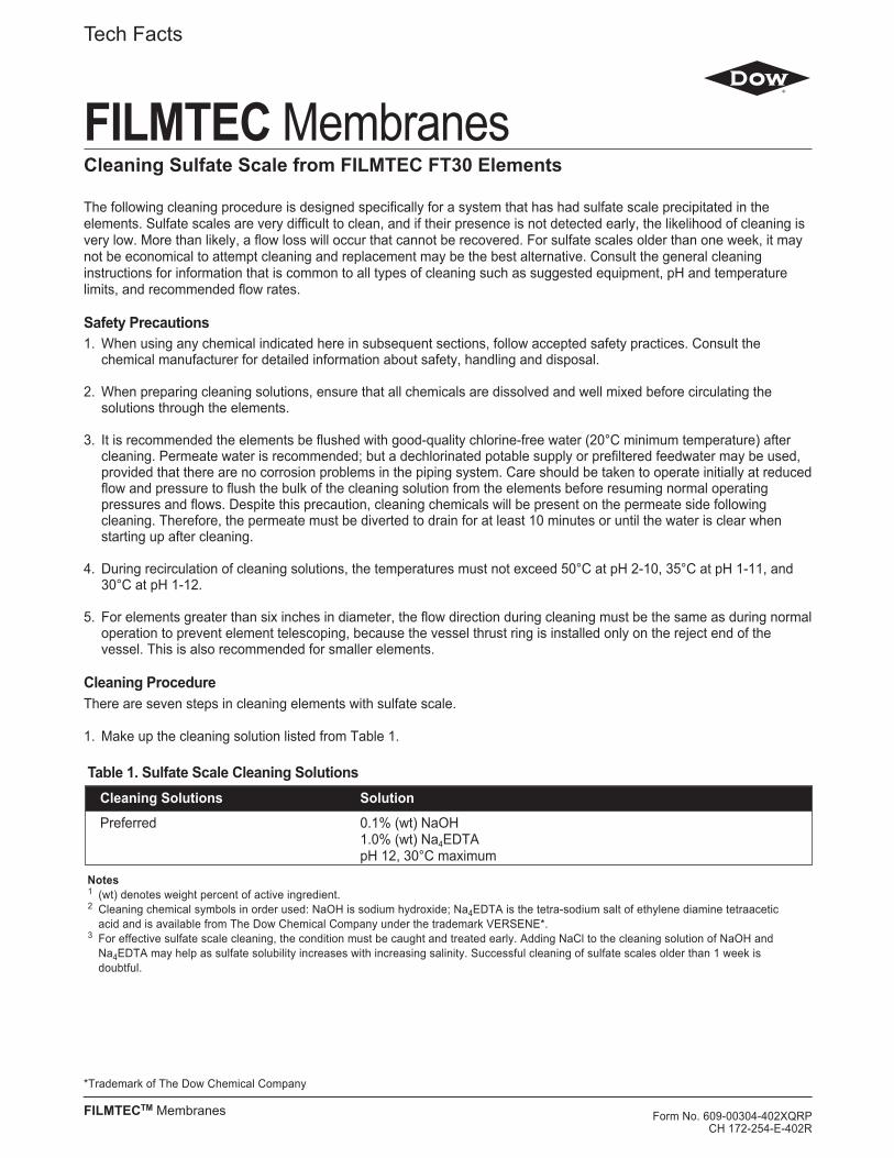
The following cleaning procedure is designed specifically for a system that has had sulfate scale precipitated in theelements. Sulfate scales are very difficult to clean, and if their presence is not detected early, the likelihood of cleaning isvery low. More than likely, a flow loss will occur that cannot be recovered. For sulfate scales older than one week, it maynot be economical to attempt cleaning and replacement may be the best alternative. Consult the general cleaninginstructions for information that is common to all types of cleaning such as suggested equipment, pH and temperaturelimits, and recommended flow rates.
Safety Precautions1. When using any chemical indicated here in subsequent sections, follow accepted safety practices. Consult the
chemical manufacturer for detailed information about safety, handling and disposal.
2. When preparing cleaning solutions, ensure that all chemicals are dissolved and well mixed before circulating thesolutions through the elements.
3. It is recommended the elements be flushed with good-quality chlorine-free water (20°C minimum temperature) aftercleaning. Permeate water is recommended; but a dechlorinated potable supply or prefiltered feedwater may be used,provided that there are no corrosion problems in the piping system. Care should be taken to operate initially at reducedflow and pressure to flush the bulk of the cleaning solution from the elements before resuming normal operatingpressures and flows. Despite this precaution, cleaning chemicals will be present on the permeate side followingcleaning. Therefore, the permeate must be diverted to drain for at least 10 minutes or until the water is clear whenstarting up after cleaning.
4. During recirculation of cleaning solutions, the temperatures must not exceed 50°C at pH 2-10, 35°C at pH 1-11, and30°C at pH 1-12.
5. For elements greater than six inches in diameter, the flow direction during cleaning must be the same as during normaloperation to prevent element telescoping, because the vessel thrust ring is installed only on the reject end of thevessel. This is also recommended for smaller elements.
Cleaning ProcedureThere are seven steps in cleaning elements with sulfate scale.
1. Make up the cleaning solution listed from Table 1.
FILMTEC Membranes
Tech Facts
*Trademark of The Dow Chemical Company
FILMTECTM Membranes
Cleaning Sulfate Scale from FILMTEC FT30 Elements
Form No. 609-00304-402XQRPCH 172-254-E-402R
Table 1. Sulfate Scale Cleaning SolutionsCleaning Solutions Solution
Preferred 0.1% (wt) NaOH1.0% (wt) Na4EDTApH 12, 30°C maximum
Notes1 (wt) denotes weight percent of active ingredient.2 Cleaning chemical symbols in order used: NaOH is sodium hydroxide; Na4EDTA is the tetra-sodium salt of ethylene diamine tetraacetic
acid and is available from The Dow Chemical Company under the trademark VERSENE*.3 For effective sulfate scale cleaning, the condition must be caught and treated early. Adding NaCl to the cleaning solution of NaOH and
Na4EDTA may help as sulfate solubility increases with increasing salinity. Successful cleaning of sulfate scales older than 1 week isdoubtful.

Table 2. Recommended feed flow rate per pressure vessel during high flow rate recirculationFeed Pressure1 Element Diameter Feed Flow Rate per Pressure Vessel
(psig) (bar) (inches) (gpm) (m3/hr)
20-60 1.5-4.0 2.5 3-5 0.7-1.220-60 1.5-4.0 42 8-10 1.8-2.320-60 1.5-4.0 6 16-20 3.6-4.5
1 Dependent on number of elements in pressure vessel.2 4-Inch full-fit elements should be cleaned at 12-14 gpm (2.7-3.2 m3/hr).3 For full-fit elements, 400 and 440 sq. ft. area elements.
3. Recirculate. After the process water is displaced, cleaning solution will be present in the concentrate stream that canbe recycled to the cleaning solution tank. Recycle the cleaning solution for 30 minutes.
4. Soak. Turn the pump off and allow the elements to soak. Soak the elements for 1-15 hours (soaking overnight willgive best results). To maintain temperature during an extended soak period, use a slow recirculation rate (about 10percent of that shown in Table 2). Soak times will vary depending on the severity of the scaling.
5. High-flow pumping. Feed the cleaning solution at the rates shown in Table 2 for 30 minutes. The high flow rateflushes out the scale removed from the membrane surface by the cleaning. If the elements are heavily scaled, a flowrate which is 50 percent higher than shown in Table 2 may aid cleaning. At higher flow rates, excessive pressure dropmay be a problem. The maximum recommended pressure drops are 15 psi per element or 50 psi per multi-elementvessel, whichever value is more limiting.
6. Flush out. Prefiltered raw water can be used for flushing out the cleaning solution, unless there will be corrosionproblems (e.g., stagnant seawater will corrode stainless steel piping). To prevent precipitation, the minimum flush outtemperature is 20°C. The system should be flushed for one hour.
7. The system should be restarted, elements and the system need to stabilize before taking any data. The stabilizationperiod will vary depending on the severity of the fouling. To regain performance it may take several cleaning and soakcycles, but for sulfate scale a permanent flow loss is expected.
2. Low-flow pumping. Pump mixed, preheated cleaning solution to the vessel at conditions of low flow rate (about half ofthat shown in Table 2) and low pressure to displace the process water. Use only enough pressure to compensate forthe pressure drop from feed to concentrate. The pressure should be low enough that essentially no permeate isproduced. A low pressure minimizes redeposition of dirt on the membrane. Dump the concentrate, as necessary, toprevent dilution of the cleaning solution.

*Trademark of The Dow Chemical Company
FILMTEC MembranesFor more information about FILMTEC membranes, call the Dow Liquid Separations business:North America . . . . . . . . . . .1-800-447-4369Latin America . . . . . . . . . . .(+55) 11-5188-9277Europe . . . . . . . . . . . . . . . .(+32) 3-450-2240Japan . . . . . . . . . . . . . . . . .(+81) 3-5460-2100Australia . . . . . . . . . . . . . . .(+61) 2-9776-3226http://www.filmtec.com
Form No. 609-00304-402XQRPCH 172-254-E-402R
NOTE: Recommendations made here are specifically designed for FILMTEC Reverse Osmosis and Nanofiltration elements. Theserecommendations, such as cleaning procedures and chemicals employed, may not be compatible with other brands of membrane elements. It isyour responsibility to ensure the suitability of our recommendations and procedures if they are applied to membrane elements other thanFilmTec products.
NOTICE: No freedom from any patent owned by Seller or others is to be inferred. Because use conditions and applicable laws may differ fromone location to another and may change with time, Customer is responsible for determining whether products and the information in thisdocument are appropriate for Customer’s use and for ensuring that Customer’s workplace and disposal practices are in compliance withapplicable laws and other governmental enactments. Seller assumes no obligation or liability for the information in this document. NOWARRANTIES ARE GIVEN; ALL IMPLIED WARRANTIES OF MERCHANTABILITY OR FITNESS FOR A PARTICULAR PURPOSE AREEXPRESSLY EXCLUDED.
Published April 2002.

Product Information
FILMTEC Membranes
*Trademark of The Dow Chemical Company
FILMTEC Membranes • FilmTec Corporation is a wholly owned subsidiary of The Dow Chemical Company.
Disinfecting RO Systems With Hydrogen Peroxide
Hydrogen peroxide or a mixture ofhydrogen peroxide and peracetic acid has been used successfully for disinfecting reverse osmosis (RO) systems that use FILMTEC®
FT30 membranes.Examples of commercial hydrogen
peroxide/peracetic acid solutions areRenalin® and Minncare® fromMinntech Corporation.
These solutions come in aconcentrated form and are diluted1:100 with RO permeate to obtain a0.25 percent peroxide solution.For more than four years, an ROsystem in Minneapolis which uses theFT30 membrane has been disinfectedonce weekly by soaking overnight indiluted Renalin. There has been noindication of membrane degradationduring this time.
There are two factors which greatlyinfluence the rate of hydrogenperoxide attack on the membrane:temperature and iron.The disinfecting solution should notexceed 25°C (77°F). FT30 membranesamples tested with 0.5 percenthydrogen peroxide at 34°C showed avery high salt passage after severalhours. At 24°C, however, membranesamples demonstrated compatibilitywith 0.5 percent hydrogen peroxideafter 96 hours.
The presence of iron or othertransition metals in conjunction withhydrogen peroxide solutions can alsocause membrane degradation.FT30 samples were tested using a0.15 percent solution of hydrogenperoxide and tapwater containing iron.After 150 hours, the salt passage ofthe membrane began to increasedramatically.
For RO systems using the FT30membrane, the following procedurefor disinfection with hydrogenperoxide or Renalin solutions isrecommended:1. Any type of deposit on themembrane or other parts of thesystem should be removed with analkaline cleaner before disinfecting.Removal of these deposits, whichharbor microorganisms, willmaximize the degree of disinfection.After alkaline cleaning, flush thesystem with RO permeate.2. Clean the RO system with acid(e.g., 0.1 percent by volumehydrochloric acid or 0.4 percent byvolume phosphoric acid) to removeany iron from the membrane surface.Flush the unit with RO permeate.3. Circulate a solution of 0.20-0.25percent hydrogen peroxide dilutedwith RO permeate at a temperaturebelow 25°C (77°F) for 20 minutes. A pH of 3-4 gives optimal biocidalresults and longer membranelifetime.4. Allow the elements to soak in thedisinfecting solution for 2-12 hours.A soak time of 2 hours would beexpected to kill more than 90 percentof the bacteria, whereas a 12-hoursoak time would achieve a 99 percent kill.
*Trademark of The Dow Chemical CompanyForm No. 609-24020-897QRP
CH 172-145-E-897
FILMTEC MembranesFor more information about FILMTEC membranes, call Dow Liquid Separations:North America . . . . . . . . . . .1-800-447-4369Latin America . . . . . . . . . . .(+55) 11-5188-9345Europe . . . . . . . . . . . . . . . .(+31) 20-691-6268Japan . . . . . . . . . . . . . . . . .(+81) 3-5460-2100Australia . . . . . . . . . . . . . . .(+61) 2-9776-3226http://www.dow.com/liquidseps
Notice: No freedom from any patent owned by Seller or others is to be inferred. Because use conditions and applicable laws may dif fer from onelocation to another and may change with time, Customer is responsible for determining whether products and the information in this document areappropriate for Customer’s use and for ensuring that Customer’s workplace and disposal practices are in compliance with applicable laws andother governmental enactments. Seller assumes no obligation or liability for the information in this document. NO WARRANTIES ARE GIVEN;ALL IMPLIED WARRANTIES OF MERCHANTABILITY OR FITNESS FOR A PARTICULAR PURPOSE ARE EXPRESSLY EXCLUDED.
Published August 1997.

DowLiquid Separations
ENGINEERING INFORMATION
FILMTECMembranesandDOWEXIon Exchange Resins

Table of Contents
1. Particle Size Distribution2. Conversion of Common Units3. Concentration of lonic Species4. Conversion of Temperature Units5. Conversion of Conductivity to Resistance6. Conductivity of Water as a Function of Temperature7. Conductivity of lonic Solutions
7.1 Conductivity vs. Concentration for lonic Solutions at 25°C7.2 Conductivity of Solutions, Acids, Alkalis and Salts at 25°C expressed as μS/cm per meq/I7.3 Conductivity of Ions Expressed as μS/cm per meq/I, infinitely diluted7.4 Conductance vs. Total Dissolved Solids7.5 Relationship Between Dissolved Solids and Conductance in Demineralization Operations7.6 Specific Conductance of Sodium Chloride
8. The pH of Pure Water as a Function of Temperature9. The pH of Basic Solutions at 25°C10. The pH of Acid Solutions at 25°C11. P- and M-Alkalinity12. Information on Regenerant Chemicals
12.1 Properties, Impurities and Concentrations12.2 Ionization and Equilibrium Data12.3 Concentration and Density of Solutions12.4 Specific Gravity of NaOH
13. Solubility of CaSO4
14. The Removal of Oxygen15. The Removal of Chlorine16. Osmotic Pressure of Sodium Chloride17. Osmotic Pressure of Solutions18. Tank Capacities, Vertical Cylindrical, in U.S. and Metric Units

Sieve Nominal Opening NominalMesh Number Sieve Opening Tolerance Wire Diameter
mm ±μm mm10 2.00 70 0.90012 1.68 60 0.81014 1.41 50 0.72516 1.19 45 0.65018 1.00 40 0.5 8020 0.841 35 0.51025 0.707 30 0.45030 0.595 25 0.39035 0.500 20 0.34040 0.420 19 0.29045 0.354 16 0.24750 0.297 14 0.21560 0.250 12 0.18070 0.210 10 0.15280 0.178 9 0.131
100 0.150 8 0.110120 0.125 7 0.091140 0.104 6 0.076170 0.089 5 0.064200 0.074 5 0.05 3230 0.064 4 0.044270 0.053 4 0.037325 0.043 3 0.030400 0.038 3 0.025
DOWEX and FILMTEC Engineering Information
1. Particle Size DistributionTest methods to establish and/orexpress the size distribution ofDOWEX* standard ion exchangeresins are based on “U.S.A. StandardSeries” of sieves. Table 1 gives themain characteristics of sieves ofinterest to the analysis of bead sizedistributions.Due to the narrow particle sizedistribution of DOWEX uniformparticle sized resins, the conventionalmethod of using U.S.A. StandardSieves does not provide sufficientlydetailed information to describe theparticle distribution effectively.The particle distribution for DOWEXuniform particle sized resins istherefore given as a mean particlesize covering a specified range and auniformity coefficient which is <1.1. Inaddition, upper and/or lowermaximum limits may be given, whichare expressed as a percentage. Thisis illustrated in Table 2.This resin therefore has a meanparticle size between 600 and 700microns with 90 percent of the beadswithin ±100 microns of the mean. Nomore than 0.2 percent of the beadpopulation is below 300 microns.
Table 1. Main Characteristics of Sieves
Table 2. Particle Distribution of DOWEX MONOSPHERE* 650C
Resin DOWEX MONOSPHERE 650CMean particle size 650 ±50 micronsUniformity Coefficient, max. 1.1Greater than 840 microns (20 mesh), max. 5%Less than 300 microns (50 mesh), max. 0.5%
*Trademark of The Dow Chemical Company

2. Conversion of Common UnitsTo convert non-metric units to themetric/S.I. units, multiply by thefactors given; to convert S.I./metricunits to the non-metric unit, divide bythe factor given in Table 3. A unitconverter is also available.
3. Concentration of lonic SpeciesTable 4 gives multiplication factors forthe conversion of concentration unitsof ionic species given as gram of theion per litre (g/I) into equivalent perlitre (eq/I) or of gram of CaCO3equivalents per litre (g CaCO3/I).Concentrations of ionic species inwater have been expressed indifferent units in different countries.Concentrations should normally beexpressed in one of the followingways:• As grams (g), milligrams (mg =
10-3 g) or micrograms (mg = 10-6 g)of the (ionic) species per litre (I) orcubic metre (m3) of water.
• As equivalents (eq) ormilliequivalents (meq = 10-3 eq) ofthe ionic species per litre (I) or cubicmetre (m3) of water.
Still widely used concentration unitsare:• Kilograins of CaCO3 per cubic foot
(kgr/ft3)• 1 French degree = 1 part CaCO3 per
100.000 parts of water• 1 German degree = 1 part CaO per
100.000 parts of water• Grains CaCO3/gallon (U. S.)• ppm CaCO3
• 1 English degree (Clark) = 1 grainCaCO3 per (British) Imperial gallonof water
Table 5 gives the conversion factorsfor commonly encountered units tomilliequivalents/litre (meq/I) and mgCaCO3/l. Multiply by the conversionfactor to obtain mg CaCO3/I or meq/I.Divide by the conversion factor toobtain the different units fromnumbers expressed as mg CaCO3/Ior meq/I.
Table 3. Conversion of Common Units
!
!
From to multiply byto from divide byLENGTHinch (in.) metre (m) 0.0254foot (ft) metre (m) 0.3048yard (yd) metre (m) 0.9144
AREAin.2 m2 0.0006452ft2 m2 0.0929yd2 m2 0.8361
VOLUMEin.3 litre (I) 0.01639ft3 litre (I) 28.32yd3 litre (I) 764.6Imp. Gallon (U.K.) litre (I) 4.546U.S. Gallon (gal.) litre (I) 3.785
MASSgrain (gr) gram (g) 0.0648Ounce gram (g) 28.35pound (Ib) gram (g) 453.6
PRESSUREAtmosphere (atm) kilo Pascal 101.3Bar kPa 100.0Ib/ft2 kPa 0.04788Ib/in.2 = psi bar 0.069Ib/in.2 = psi kPa 6.895
PRESSURE DROPpsi/ft kPa/m 22.62
VISCOSITYpoise Pascal-second (Pa s) 0.1
FLOW RATEgal./min. = gpm m3/hr 0.227gal./min. = gpm l/sec 0.063gal./day = gpd m3/day 0.003785gal./day = gpd l/hr 0.158million gal./day = mgd m3/hr 157.73gal./day = gpd m3/day 3785Imp gpm m3/hr 0.273
FLOW VELOCITYgpm/ft2 m/h 2.445gpd/ft2 l/m2hr 1.70
SERVICE FLOW RATEgpm/ft3 (m3/h)/m3 8.02
RINSE VOLUMEgal./ft3 l/l 0.134
CHEMICAL DOSAGEIb/ft3 g/I 16.0
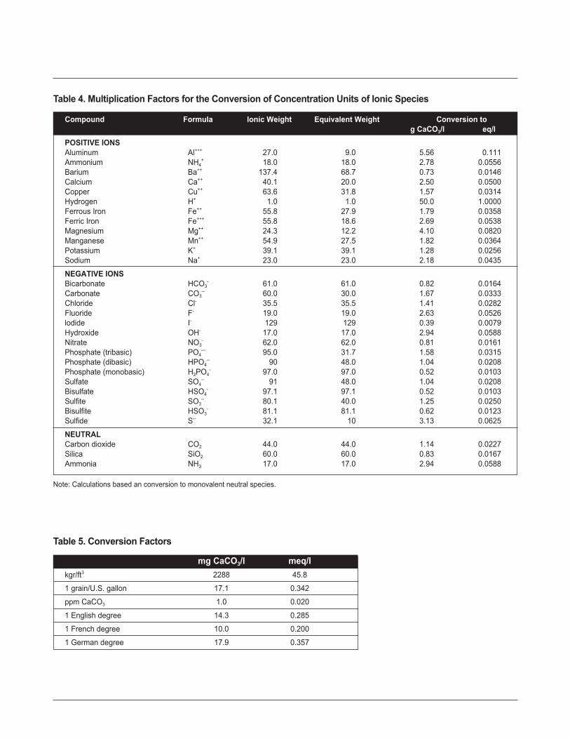
mg CaCO3/l meq/lkgr/ft3 2288 45.8
1 grain/U.S. gallon 17.1 0.342
ppm CaCO3 1.0 0.020
1 English degree 14.3 0.285
1 French degree 10.0 0.200
1 German degree 17.9 0.357
Compound Formula lonic Weight Equivalent Weight Conversion tog CaCO3/I eq/I
POSITIVE IONSAluminum Al+++ 27.0 9.0 5.56 0.111Ammonium NH4
+ 18.0 18.0 2.78 0.0556Barium Ba++ 137.4 68.7 0.73 0.0146Calcium Ca++ 40.1 20.0 2.50 0.0500Copper Cu++ 63.6 31.8 1.57 0.0314Hydrogen H+ 1.0 1.0 50.0 1.0000Ferrous Iron Fe++ 55.8 27.9 1.79 0.0358Ferric Iron Fe+++ 55.8 18.6 2.69 0.0538Magnesium Mg++ 24.3 12.2 4.10 0.0820Manganese Mn++ 54.9 27.5 1.82 0.0364Potassium K+ 39.1 39.1 1.28 0.0256Sodium Na+ 23.0 23.0 2.18 0.0435
NEGATIVE IONSBicarbonate HCO3
- 61.0 61.0 0.82 0.0164Carbonate CO3
-- 60.0 30.0 1.67 0.0333Chloride Cl- 35.5 35.5 1.41 0.0282Fluoride F- 19.0 19.0 2.63 0.0526lodide I- 129 129 0.39 0.0079Hydroxide OH- 17.0 17.0 2.94 0.0588Nitrate NO3
- 62.0 62.0 0.81 0.0161Phosphate (tribasic) PO4
--- 95.0 31.7 1.58 0.0315Phosphate (dibasic) HPO4
-- 90 48.0 1.04 0.0208Phosphate (monobasic) H2PO4
- 97.0 97.0 0.52 0.0103Sulfate SO4
-- 91 48.0 1.04 0.0208Bisulfate HSO4
- 97.1 97.1 0.52 0.0103Sulfite SO3
-- 80.1 40.0 1.25 0.0250Bisulfite HSO3
- 81.1 81.1 0.62 0.0123Sulfide S-- 32.1 10 3.13 0.0625
NEUTRALCarbon dioxide CO2 44.0 44.0 1.14 0.0227Silica SiO2 60.0 60.0 0.83 0.0167Ammonia NH3 17.0 17.0 2.94 0.0588
Table 4. Multiplication Factors for the Conversion of Concentration Units of Ionic Species
Note: Calculations based an conversion to monovalent neutral species.
Table 5. Conversion Factors

Compounds Formula Molecular Equivalent Substance CaCO3
Weight Weight to CaCO3 equivalent toequivalent Substance
multiply byAluminum Sulfate (anhydrous) Al2(SO4)3 342.1 57.0 0.88 1.14Aluminum Hydroxide AI(OH)3 78.0 26.0 1.92 0.52Aluminum Oxide (Alumina) Al2O3 101.9 17.0 2.94 0.34Sodium Aluminate Na2Al2O4 163.9 27.3 1.83 0.55Barium Sulfate BaSO4 233.4 116.7 0.43 2.33Calcium Bicarbonate Ca(HCO3)2 162.1 81.1 0.62 1.62Calcium Carbonate CaCO3 100.1 50.0 1.00 1.00Calcium Chloride CaCl2 111.0 55.5 0.90 1.11Calcium Hydroxide Ca(OH)2 74.1 37.1 1.35 0.74Calcium Oxide CaO 56.1 28.0 1.79 0.56Calcium Sulfate (anhydrous) CaSO4 136.1 68.1 0.74 1.36Calcium Sulfate (gypsum) CaSO4 • 2H2O 172.2 86.1 0.58 1.72Calcium Phosphate Ca3(PO4)2 310.3 51.7 0.97 1.03Ferrous Sulfate (anhydrous) FeSO4 151.9 76.0 0.66 1.52Ferric Sulfate Fe2(SO4)3 399.9 66.7 0.75 1.33Magnesium Oxide MgO 40.3 20.2 2.48 0.40Magnesium Bicarbonate Mg(HCO3)2 146.3 73.2 0.68 1.46Magnesium Carbonate MgCO3 84.3 42.2 1.19 0.84Magnesium Chloride MgCl2 95.2 47.6 1.05 0.95Magnesium Hydroxide Mg(OH)2 58.3 29.2 1.71 0.58Magnesium Phosphate Mg3(PO4)2 262.9 43.8 1.14 0.88Magnesium Sulfate (anhydrous) MgSO4 120.4 60.2 0.83 1.20Magnesium Sulfate (Epsom Salts) MgSO4 - 7H2O 246.5 123.3 0.41 2.47Manganese Chloride MnCl2 125.8 62.9 0.80 1.26Manganese Hydroxide Mn(OH)2 89.0 44.4 1.13 0.89Potassium lodine KI 166.0 166.0 0.30 3.32Silver Chloride AgCI 143.3 143.3 0.35 2.87Silver Nitrate AgNO3 169.9 169.9 0.29 3.40Silica SiO2 60.1 30.0 1 .67 0.60Sodium Bicarbonate NaHCO3 84.0 84.0 0.60 1.68Sodium Carbonate Na2CO3 106.0 53.0 0.94 1.06Sodium Chloride NaCl 58.5 58.5 0.85 1.17Sodium Hydroxide NaOH 40.0 40.0 1.25 0.80Sodium Nitrate NaNO3 85.0 85.0 0.59 1.70Tri-sodium Phosphate Na3PO4 • 12H2O 380.2 126.7 0.40 2.53Tri-sodium Phos. (anhydrous) Na3PO4 164.0 54.7 0.91 1.09Disodium Phoshate Na2HPO4 • 12H2O 358.2 119.4 0.42 2.39Disodium Phos. (anhydrous) Na2HPO4 142.0 47.3 1.06 0.95Monosodium Phosphate NaH2PO4 - H20 138.1 46.0 1.09 0.92Monosodium Phos. (anhydrous) NaH2PO4 120.0 40.0 1.25 0.80Sodium Metaphosphate NaPO3 102.0 34.0 1.47 0.68Sodium Sulfate Na2SO4 142.1 71.0 0.70 1.42Sodium Sulfite Na2SO4 126.1 63.0 0.79 1.26
Table 6. Calcium Carbonate (CaCO3) Equivalent of Common Substances

4. Conversion of TemperatureUnitsConversions of temperature unitsbetween °C and °F can be madegraphically using the grid in Figure 1or by mathematical conversion usingfollowing equations:
°C to °F: (9/5 x °C) + 32 = °F°F to °C: 5/9 (°F – 32) = °C
The S.I. unit is °C.
5. Conversion of Conductivity toResistanceThe salt content of a water or theimpurities left after ion exchange arecommonly expressed in terms ofconductivity, expressed as Siemensper centimeter (S/cm) for a standardmeasuring cell with a cell constant of1 cm (see Figure 2).As the conductivity is the reciprocal ofthe resistance, such characteristicscan alternatively be expressed inOhm multiplied by centimeter (Ωcm)whereby:
S 1Scm-1 = ---- = ---- = Ω-1cm-1
cm ΩcmConsequently, the following units ofconductivity and resistance aredifferent expressions relating to thesame situation:
10-6 S/cm = 1 μS/cm ~ 1 MΩcm =106 Ωcm10-3 S/cm = 1 mS/cm ~ 1 kΩcm =103 Ωcm
0.01 0.1 1 10 100
100
10
1
0.1
0.01
Electrical Resistance (106 Ωcm = MΩcm)
Ele
ctric
al C
ondu
ctiv
ity (μ
S/c
m)
Figure 2. Conversion of Conductivity to Resistance
0 20 40 60 80 100 120 140 160 180 200 220 240 260 280 300
150
140
130
120
110
100
90
80
70
60
50
40
30
20
10
0
Temperature (°F)
Tem
pera
ture
(°C
)
Figure 1. Conversion of Temperature Units

6. Conductivity of Water asFunction of the TemperatureThe conductivity of water, free of anyimpurities, will vary with temperatureas presented in Figure 3 inaccordance with its changing degreeof auto-dissociation into H+ and OH–
and the different mobilities of theseions at different temperatures.
7. Conductivity of lonic SolutionsFigures 4 through 7 show therelationship of the conductivity of asolution containing one givenchemical, to the concentration of thischemical.The conductivity of solutions at othertemperatures can be calculated bymultiplying conductivities at 25°C(77°F) with the correction factors inTable 7. These factors are only validfor diluted solutions as they supposetotal ionic dissociation of thechemical.
0 10 20 30 40 50 60 70 80 90 100
1.0
0.8
0.6
0.4
0.2
0.1
0.08
0.06
0.04
0.02
0.01
Temperature (°C)
Con
duct
ivity
(μS
/cm
)
Figure 3. Conductivity of Water as Function of the Temperature
0 1 2 3 4 5 6 7 8 9 10
22
20
18
16
14
12
10
8
6
4
2
0
Concentration (g/m3 [mg/l])
Con
duct
ivity
(μS
/cm
)
CO2
HCl H2SO4
NaOH KOH
NaCl
NH3
Figure 4. Conductivity vs. Concentration for lonic Solutions at 25°C

0°C 18°C 25°C 50°C(32°F) (64°F) (77°F) (122°F)
HCl 0.66 0.89 1.00 1.37
H2SO4 0.66 0.87 1.00 1.38
NaCl 0.53 0.86 1.00 1.57
NaOH 0.54 0.89 1.00 1.51
KOH 0.55 0.89 1.00 1.50
Table 7. Conductivity of Solutions at Other Temperatures
CO2
HCl
H2SO4
NaOH
KOH
NaCl
NH3
0.1 0.2 0.4 0.6 0.8 1 2 4 6 8 10 20 40 60 80 100
100
80
60
40
20
10
8
6
4
2
1
0.8
0.6
0.4
0.2
0.1
Concentration (g/m3 [mg/l])
Con
duct
ivity
(μS
/cm
)
Figure 5. Conductivity vs. Concentrations for Ionic Solutions at 25°C

Ion 20°C (68°F) 25°C (77°F) 100°C (212°F)H+ 328 350 646Na+ 45 50.1 155K+ 67 73.5 200NH4
+ 67 73.5 200Mg++ 47 53.1 170Ca++ 53.7 59.5 191OH– 179 197 446Cl– 69.0 76.3 207HCO3 36.5 44.5 -NO3
– 65.2 71.4 178H2PO4
– 30.1 36.0 -CO3
– – 63.0 72.0 -HPO4
– – - 53.4 -SO4
– – 71.8 79.8 234PO4
– – – - 69.0 -
Table 9. Conductivity of Ions Expressed as μS/cm per meq/l, InfinitelyDiluted
Component Concentration in meg/linfin. diluted 0.1 0.5 1.0 5.0 10.0 50.0 100.0
HCl 426 425 423 421 415 412 399 392HNO3 421 420 417 416 410 407 394 386H2SO4 430 424 412 407 390 380 346 317H3PO4 419 394 359 336 264 223 133 104NaOH 248 247 246 245 241 238 227 221KOH 271 270 269 268 264 261 251 246NH4OH 271 109 49 36 17 12 5.6 3.9NaCl 126 126 124 124 121 118 111 107Na2SO4 130 128 126 124 117 113 97.7 90.0Na2CO3 124 122 120 119 112 108 93.2 86.3NaHCO3 96.0 95.2 94.2 93.5 90.5 88.4 80.6 76.0KCI 150 149 148 141 144 141 133 129
Table 8. Conductivity of Solutions, Acids, Alkalis and Salts at 25°C Expressed as μS/cm per meq/l
Source: Landolt Börnstein 6° edition Band II/7.
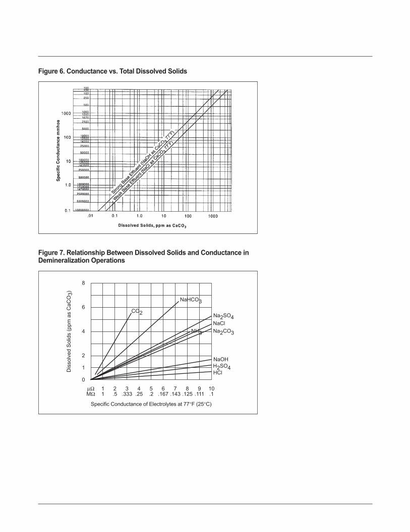
Figure 6. Conductance vs. Total Dissolved Solids
μΩ 1 2 3 4 5 6 7 8 9 10MΩ 1 .5 .333 .25 .2 .167 .143 .125 .111 .1
8
6
4
2
1
0
Specific Conductance of Electrolytes at 77°F (25°C)
Dis
solv
ed S
olid
s (p
pm a
s C
aCO
3)
CO2
HCl
Na2SO4
NaOH
NaClNH3
NaHCO3
H2SO4
Na2CO3
Figure 7. Relationship Between Dissolved Solids and Conductance inDemineralization Operations
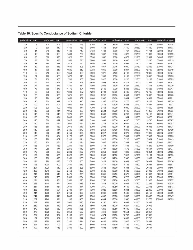
μmhos/cm ppm μmhos/cm ppm μmhos/cm ppm μmhos/cm ppm μmhos/cm ppm μmhos/cm ppm μmhos/cm ppm
10 5 620 307 1440 723 3350 1726 8600 4654 20000 11476 50000 3042520 9 630 312 1460 733 3400 1753 8700 4710 20250 11630 51000 3110330 14 640 317 1480 743 3450 1781 8800 4767 20500 11784 52000 3178140 19 650 323 1500 754 3500 1808 8900 4823 20750 11937 53000 3245960 28 660 328 1525 766 3550 1835 9000 4879 21000 12091 54000 3313770 33 670 333 1550 770 3600 1863 9100 4935 21250 12245 55000 3381580 38 680 338 1575 792 3650 1899 9200 4991 21500 12399 56000 3449390 42 690 343 1600 805 3700 1917 9216 5000 21750 12552 57000 35171
100 47 700 348 1625 817 3750 1945 9300 5047 22000 12705 58000 35849110 52 710 353 1650 830 3800 1972 9400 5103 22250 12860 59000 36527120 57 720 358 1675 843 3850 1999 9500 5159 22500 13013 60000 37205130 61 730 363 1700 856 3900 2027 9600 5215 22750 13167 61000 37883140 66 740 368 1725 868 3950 2054 9700 5271 23000 13321 62000 38561150 71 750 373 1750 881 4000 2081 9800 5327 23250 13474 63000 39239160 75 760 378 1775 894 4100 2136 9900 5383 23500 13628 64000 39917170 80 770 383 1800 907 4200 2191 10000 5439 23750 13782 65000 40595180 85 780 388 1825 920 4300 2245 10200 5551 24000 13936 66000 41273190 90 790 393 1850 932 4400 2300 10400 5664 24250 14089 67000 41961200 95 800 399 1875 945 4500 2356 10600 5776 24500 14243 68000 42629210 100 810 404 1900 958 4600 2412 10800 5888 24750 14397 69000 3307220 105 820 409 1925 971 4700 2468 11000 6000 25000 14550 70000 43985230 110 830 414 1950 983 4800 2524 11200 6122 25500 14858 71000 44663240 115 840 419 1975 996 4900 2580 11400 6243 26000 15165 72000 45341250 120 850 424 2000 1000 5000 2636 11600 364 26500 15473 73000 46091260 125 860 429 2025 1022 5100 2692 11800 6485 27000 15780 74000 46697270 130 870 434 2050 1034 5200 2748 12000 6607 27500 16087 76000 48053280 135 880 439 2075 1047 5300 2805 12200 6728 28000 16395 77000 48731290 140 890 444 2125 1073 5400 2861 12400 6843 28500 16702 78000 49409300 145 900 449 2150 1085 5500 2917 12600 6970 29000 17010 79000 50087310 150 910 454 2175 1098 5600 2973 12800 7091 29500 17317 80000 50765320 155 920 459 2200 1111 5700 3029 13000 7213 30000 17624 81000 51443330 160 930 464 2225 1124 5800 3085 13200 7334 30500 17932 82000 52121340 165 940 469 2250 1137 5900 3141 13400 7455 31000 18239 83000 52799350 171 950 474 2275 1140 6000 3197 13600 7576 31500 18547 84000 53477360 176 960 480 2300 1162 6100 3253 13800 7898 32000 18854 85000 54155370 181 970 485 2325 1175 6200 3309 14000 7819 32500 19161 86000 54833380 186 980 490 2350 1188 6300 3365 14200 7940 33000 19469 87000 55511390 191 990 495 2375 1200 6400 3421 14400 8061 34000 20084 88000 56130400 196 1000 500 2400 1213 6500 3477 14600 8182 34500 20391 89000 56867410 201 1020 510 2425 1226 6600 3533 14800 8304 35000 20698 90000 57545420 206 1040 520 2450 1239 6700 3589 15000 8425 35500 21006 91000 58223430 211 1080 540 2475 1251 6800 3645 15250 8576 36000 21313 92000 58901440 216 1100 550 2500 1264 6900 3701 15500 8728 36500 21621 93000 59579450 221 1120 561 2550 1290 7000 3758 15750 8879 37000 21928 94000 60257460 226 1140 571 2600 1315 7100 3814 16000 9031 37500 22235 95000 60935470 231 1160 581 2650 1344 7200 3870 16250 9182 38000 22543 96000 61613480 236 1180 591 2700 1371 7300 3926 16500 9334 38500 22850 97000 62291490 241 1200 601 2750 1398 7400 3982 16750 9486 39000 23158 98000 62969500 247 1220 611 2800 1426 7500 4038 17000 9637 39500 23465 99000 63647510 252 1240 621 285 1453 7600 4094 17500 9940 40000 23773 100000 64325520 257 1260 632 2900 1480 7700 4150 1775 10092 41000 24387530 262 1280 642 2950 1508 7800 4206 18000 10247 42000 25002550 272 1300 652 3000 1535 7900 4262 18250 10400 43000 25679560 277 1320 662 3050 1562 8000 4318 18500 10554 44000 26357570 282 1340 672 3100 1589 8100 4374 18750 10708 45000 27035580 87 1360 682 3150 1617 8200 4430 19000 10852 46000 27713590 292 1380 692 3200 1644 8300 4486 19250 11015 47000 28391600 297 1400 702 3250 1671 8400 4542 19500 11169 48000 29069610 302 1420 713 3300 1699 8500 4598 19750 11323 49000 29747
Table 10. Specific Conductance of Sodium Chloride
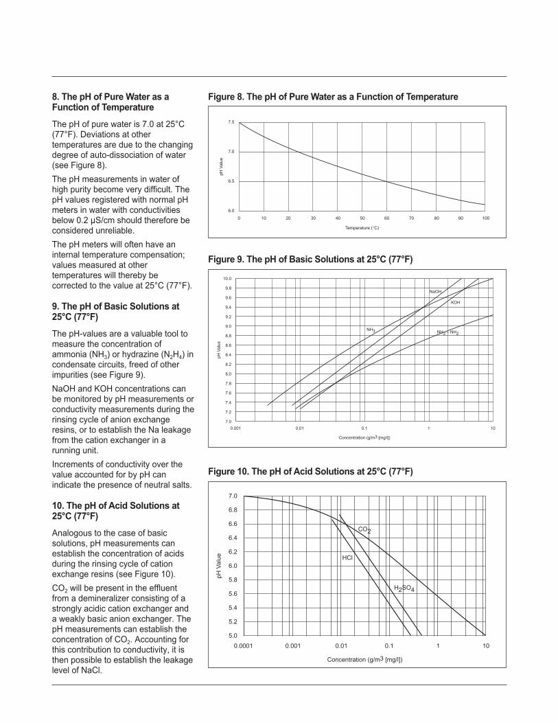
8. The pH of Pure Water as aFunction of TemperatureThe pH of pure water is 7.0 at 25°C(77°F). Deviations at othertemperatures are due to the changingdegree of auto-dissociation of water(see Figure 8).The pH measurements in water ofhigh purity become very difficult. ThepH values registered with normal pHmeters in water with conductivitiesbelow 0.2 μS/cm should therefore beconsidered unreliable.The pH meters will often have aninternal temperature compensation;values measured at othertemperatures will thereby becorrected to the value at 25°C (77°F).
9. The pH of Basic Solutions at25°C (77°F)The pH-values are a valuable tool tomeasure the concentration ofammonia (NH3) or hydrazine (N2H4) incondensate circuits, freed of otherimpurities (see Figure 9).NaOH and KOH concentrations canbe monitored by pH measurements orconductivity measurements during therinsing cycle of anion exchangeresins, or to establish the Na leakagefrom the cation exchanger in arunning unit.Increments of conductivity over thevalue accounted for by pH canindicate the presence of neutral salts.
10. The pH of Acid Solutions at25°C (77°F)Analogous to the case of basicsolutions, pH measurements canestablish the concentration of acidsduring the rinsing cycle of cationexchange resins (see Figure 10).CO2 will be present in the effluentfrom a demineralizer consisting of astrongly acidic cation exchanger anda weakly basic anion exchanger. ThepH measurements can establish theconcentration of CO2. Accounting forthis contribution to conductivity, it isthen possible to establish the leakagelevel of NaCl.
0 10 20 30 40 50 60 70 80 90 100
7.5
7.0
6.5
6.0
Temperature (°C)pH
Val
ue
Figure 8. The pH of Pure Water as a Function of Temperature
0.0001 0.001 0.01 0.1 1 10
7.0
6.8
6.6
6.4
6.2
6.0
5.8
5.6
5.4
5.2
5.0
Concentration (g/m3 [mg/l])
pH V
alue
H2SO4
HCl
CO2
Figure 10. The pH of Acid Solutions at 25°C (77°F)
0.001 0.01 0.1 1 10
10.0
9.8
9.6
9.4
9.2
9.0
8.8
8.6
8.4
8.2
8.0
7.8
7.6
7.4
7.2
7.0
Concentration (g/m3 [mg/l])
pH V
alue
NH2 – NH2
NaOH
KOH
NH3
Figure 9. The pH of Basic Solutions at 25°C (77°F)

11. P- and M-AlkalinityAlkalinity titrations are carried outusing an acid solution of 0.1 N and a100 ml water sample, or using a 1 Nsolution and a 1 I water sample. Thevolume of acid, expressed in ml ofacid added to cause colour change ofthe indicator is reported as alkalinity;therefore:1 ml acid = 1 meq/I alkalinityIf phenolphthalein is used asindicator, P-alkalinity is measured. Ifmethylorange is used, M-alkalinity ismeasured.Although alkalinity numbers as suchare interesting, it is also necessary toknow the concentrations of thespecies making up this alkalinity; themain contributors are hydroxyl (OH–),bicarbonate (HCO3
–) and carbonate(CO3
– –) ions. Their concentrationscan be calculated from P- andM-alkalinity assuming:1. P-alkalinity determines all hydroxyl
and half of the carbonate alkalinity.2. M-alkalinity determines the total of
carbonate, bicarbonate andhydroxyl alkalinity.
Table 11 can then be used tocalculate the concentrations of thedifferent species for different cases ofP- and M-alkalinity. Results areobtained in meq/I.Example: If P-alkalinity is 0.5 ml andM-alkalinity is 3 ml, then P < 1/2 Mapplies
! carbonate = 1.0 meq/I! bicarbonate = 2.0 meq/I
12. Information on RegenerantChemicals12.1 Properties, Impurities andConcentrationsGeneralSufficient precautions should betaken when handling, transporting ordisposing of acidic or basicregenerants. Even after dilution totheir operational concentrations or inthe waste after regeneration,sufficient acid or base can be presentto cause severe damage to mankind.Adequate protection for all parts ofthe body should therefore be providedwhenever using these chemicals, andthe manufacturer’s guidelines for
handling these products should becarefully followed.The specifications and the purity ofthe regenerant chemicals have toassure a trouble-free operation of theion exchange resin after regeneration.Therefore, the chemicals have to befree of suspended materials, or othermaterials that may be precipitatedand/or absorbed by the resin. Theyshould also be free of ionic speciesother than the active regenerationagents, as this will decrease theregeneration efficiency and/orincrease the leakage of this speciesduring the operational cycle. Forexample, sodium hydroxidecontaining 2 percent NaCl will reducethe efficiency by 5 to 10 percent andcause a higher Cl-leakage from thestrongly basic anion exchange resin.In counter-current operations wherelow leakage levels are especiallyaimed for, regenerants should containminimal levels of impurities.Different processes and technologiesand different requirements as to thequality of the treated effluent willtherefore impose different restrictionson the impurity levels in theregeneration chemicals and thedilution water. In the same way,regenerant concentrations and flowrates can affect the efficiency of theoperation.Recommendations and the quality ofregeneration chemicals are given inthe following sections. Therecommended qualities should provesufficient for all ion exchange resinapplications, and under certainconditions lesser qualities can beused, including eventual wastechemicals from process streams.Figures for impurity levels are thebasis of a 100 percent regenerationchemical.1. Hydrochloric Acid: HCl (MuriaticAcid) Both as a gas and in solution,HCl is very corrosive and can causesevere burns on contact. Mucousmembranes of the eyes and of theupper respiratory tract are especiallysusceptible to high atmosphericconcentrations. Avoid inhalation of
P and M Hydroxyl Carbonate Bicarbonatealkalinity (OH) (CO3) (HCO3)P = O 0 0 M
P < 1/2 M 0 2P M - 2P
P = 1/2 M 0 M 0
P > 1/2 M 2P-M 2(M-P) 0
P = M M 0 0
Table 11. Calculating Concentrations for P- and M-Alkalinity
Recommended Max. Impurity LevelsFe 0.01%
Other metals, total 10 mg/I
Organic matter 0.01%
Sulfuric acid, as SO3 0.4%
Oxidants (HNO3, Cl2) 5 mg/l
Suspended matter as turbidity ~ 0
Inhibitors None
Table 12. Recommended Maximum Impurity Levels for HCl

the fumes and provide adequateventilation when handling the acid.The acid is commercially offered as acolorless to light yellow/green liquid inconcentrations of about 28 to 36weight to weight percent HCl (seeTable 12).Hydrochloric acid from hydrolysis ofchlorinated organic materials is notsuitable for use as regenerant. Acidfrom the salt-acid process or by thehydrogen-chlorine process issatisfactory.Hydrochloric acid solutions are mostdiluted to 4 to 5 percent for theregeneration of strongly acidic ionexchangers, and from 1 to 5 percentfor weakly acidic resins in waterdemineralization applications. Higherconcentrations using 8 to 10 percentHCl are sometimes preferred in otherapplications.2. Sulfuric Acid: H2SO4 Sulfuric acidis dangerous when improperlyhandled. Concentrated solutions arerapidly destructive to tissues theycontact, producing severe burns.Contact with eyes will cause severedamage and blindness. Inhalingvapors from hot acid or oleum may beharmful. Swallowing may causesevere injury or death. One should bewell aware of the strong exothermicityof the dilution of H2SO4 with water,which can raise the temperature veryhigh and very fast. The acid issupplied as a colorless toyellow/brown liquid in concentrationsof about 93 weight percent.Sulfuric acid solutions are mostlydiluted to 1 to 6 percent for theregeneration of strongly acidic ionexchangers and to 0.5 to 1 percentfor weakly acidic ion exchangers inwater demineralization applications.Stepwise increase of the acidconcentration may be preferred undercircumstances of high-hardnesswaters (see Table 13).3. Sodium Hydroxide: NaOH(Caustic Soda) Sodium hydroxide orcaustic soda can cause severe burnson contact with skin or eyes or whentaken internally. Great care must be
taken when handling the anhydrousmaterial or when preparing orhandling caustic soda solutions.Caustic soda is offered as solid flakesor pellets of about 98 percent NaOHor as a 30 to 50 percent liquid (seeTable 14).Mercury cell or purified diaphragmcell (rayon) quality sodium hydroxidewill normally meet suchspecifications. Regular diaphragm cell
quality caustic soda can contain over2 percent NaCl and over 0.1 percent(1000 mg/I) NaClO3.Sodium hydroxide solutions aremostly diluted to between 2 and 5percent for the regeneration of weaklyor strongly basic resins.Regeneration of strongly basic resinscan eventually be carried out withNaOH containing higher NaClconcentrations at the expense
Recommended Max. Impurity LevelsFe 50 mg/I
Nitrogen compounds 20 mg/I
As 0.2 mg/I
Organic matter 0.01%
Suspended matter as turbidity ~ 0
Inhibitors None
Other heavy metals 20 mg/I
Table 13. Recommended Maximum Impurity Levels for H2SO4
Recommended Max. Impurity LevelsNaCl 0.6%
NaClO3 30 mg/I
Na3CO3 0.75%
Fe 10 mg/I
Heavy metals (total) 5 mg/I
SiO3 50 mg/I
Na2SO4 0.2%
Table 14. Recommended Maximum Impurity Levels for NaOH
Compound Mercury1 Rayon1 Regular RegularGrade Grade Diaphragm Technical
Grade FlakeNaOH 51% 50.1% 50.4% 98%
Na2CO3 0.02% 0.2% 0.2% 0.5-1%
NaClO3 1 mg/l 2 mg/l 0.5%l 2 mg/l
NaCl 0.002% 0.2-.05% 1-2% 0.4-1.5%
NaSO4 10 mg/l 0.1%l 0.03% 0.3%
Fe 1 mg/l 10 mg/l 15 mg/l 10 mg/l
Heavy metals (total) 2 mg/l 4 mg/l N.S. 2 mg/l
SiO2 10 mg/l 40 mg/l N.S. 500 mg/l
Table 15. Typical Analyses for Different Caustic Qualities

however, of efficiency (2 percentNaCl will cause about 10 percentreduction in efficiency). NaClO3 levelsof 500 mg/I can be allowed forstrongly basic resins in single beds.Weakly basic resins will suffer mostlyfrom high NaClO3 levels asconversion to HClO3 can create astrong oxidizing agent. Therefore,mixed bed anion exchangers shouldbe regenerated with regular gradediaphragm cell caustic soda. On theother hand, regeneration of weaklybasic resins will not suffer from highNaCl, Na2SO4 or NaCO3 levels. Ifvery low chloride levels are required,mercury grade NaOH should be used.Typical analyses for different causticqualities are given in Table 15.4. Ammonia: NH3 Ammonia gas orfumes from concentrated solutionscan cause serious irritation to eyesand the respiratory tract. Avoidinhalation and provide adequateventilation when handling ammoniasolutions.Ammonia is mostly offered as asolution in water, containing 20 to 30weight percent NH3. Impurities arenormally minimal and cause nopotential problem in ion exchangeregeneration.Ammonia is mostly used inconcentrations between 3 and 5percent for regeneration of weakly tomedium basic anion exchange resins.5. Sodium Carbonate: NaCO3 (SodaAsh) Sodium carbonate does notrequire special handling precautions.It is supplied as a white, anhydrouspowder with over 98 percent purity.Impurity levels are thus minimal andcause no potential problem in ionexchange regeneration. Moreover,higher levels of NaCl or Na2SO4 willnot adversely affect the regenerationefficiency, although they will of coursenot contribute as regenerationchemicals.Sodium carbonate is mostly diluted tobetween 5 and 8 percent for theregeneration of weakly to mediumbasic ion exchange resins.
6. Sodium Chloride: NaCl (Salt)Sodium chloride does not requirespecial handling precautions. It isoffered as a white powdered,granulated or pelleted solid of 98 to99 percent (see Table 16).Sodium chloride is used forregeneration in different processes.Concentrations will differ dependingupon the process, as is illustrated inTable 17.
12.2 Ionization and EquilibriumDataSulfuric acid has two acidic protons(H+). The first H+ is very acidic andwill appear as an ion in all but veryconcentrated solutions. Ionization ofthe second H+, leaving free SO4
– – insolutions happens, however, only inmore diluted solutions. Figures 11and 12 give the proportions of non-ionized H2SO4, the partially ionizedacid (HSO4
–) and proportions of thefully ionized acid (SO4
– –) as functionsof the acid concentration.
Recommended Max. Impurity LevelsSO4
- - 1%
Mg+++Ca++ 0.5%
Table 16. Recommended Maximum Impurity Levels for NaCl
Process Resin ConcentrationSoftening e.g., DOWEX MARATHON C 8-26% NaCl
Dealkalization e.g., DOWEX MARATHON A2 5-10% NaCl
Organic screen e.g., DOWEX MARATHON 11 10% NaCl + 1% NaOH
Table 17. Concentration of NaCl and Process Used
0 20 40 60 80 100
100
80
60
40
20
0
Weight % H2SO4 in Solution
Mol
Fra
ctio
nS
O4–
– x
100
H2SO4
Mol
Fra
ctio
n H
2SO
4 x
100
SO4– –
HSO4–
0
20
40
60
80
100
Figure 11. Ionization of Sulfuric Acid

1. Sulfate/Bisulfate Equilibrium asFunction of pH at 25°C (77°F) In thepresence of other acids/bases theequilibrium between bisulfate (HSO4
–)and sulfate (SO4
– –) will be shifted asa function of the overall pH of thesolution. Figure 13 shows theproportions of HSO4
– and SO4– – for
diluted solution at 25°C (77°F).2. Ionization of Diluted AmmoniaSolutions as Function of the pH at25°C (77°F) Ammonia (NH3) is aweak base, accepting H+ in acidic andweakly basic media, but not instrongly basic solutions. Figure 14allows to establish the proportion ofprotonated ammonia, appearing asan ammonium ion (NH4
+), and freeammonia (NH3) at different pHvalues. At pH 7 or lower, all ammoniawill be present as NH4
+; at pH 12 orhigher, only free ammonia will bepresent.3. Ionization of Carbon DioxideSolutions as Function of the pH at25°C (77°F) Carbon dioxide (CO2),also present as carbonic acid(H2CO3), is a weak acid with twoweakly acidic protons. Dependingupon the pH of the solution, the acidwill be present as free acid (CO2),partially ionized, leaving bicarbonate(HCO3
–) in the solution, or fullyionized, leaving carbonate (CO3
– –) inthe solution. The proportions of thedifferent species at different pHvalues can be established fromFigure 15.
0 2 4 6 8 10
100
80
60
40
20
0
Weight % H2SO1 in Solution
Mol
Fra
ctio
nS
O4–
– x
100
Mol
Fra
ctio
n H
SO
4–
x 10
0
SO4– –
HSO4–
0
20
40
60
80
100
Figure 12. Ionization of Diluted H2SO4 Solutions at 25°C (77°F)
0 1 2 3 4 5
100
80
60
40
20
0
pH Value
Mol
Fra
ctio
nS
O4–
– x
100
Mol
Fra
ctio
n H
SO
4–
x 10
0SO4– –
HSO4–
0
20
40
60
80
100
Figure 13. Sulfate/Bisulfate Equilibrium as Function of pH at 25°C (77°F)
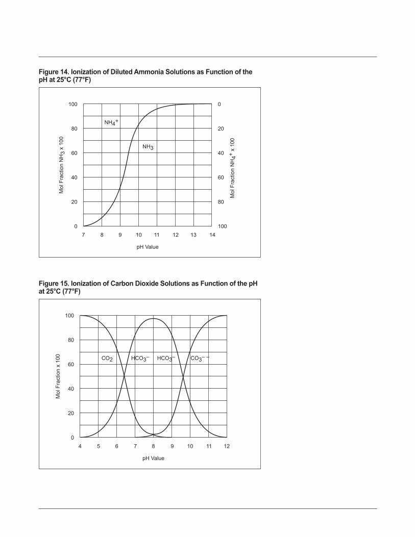
7 8 9 10 11 12 13 14
100
80
60
40
20
0
pH Value
Mol
Fra
ctio
nN
H3
x 10
0
Mol
Fra
ctio
n N
H4+
x 10
0
NH4+
NH3
0
20
40
60
80
100
Figure 14. Ionization of Diluted Ammonia Solutions as Function of thepH at 25°C (77°F)
4 5 6 7 8 9 10 11 12
100
80
60
40
20
0
pH Value
Mol
Fra
ctio
n x
100 CO2 HCO3–HCO3– CO3– –
Figure 15. Ionization of Carbon Dioxide Solutions as Function of the pHat 25°C (77°F)

12.3 Concentration and Density ofSolutionsTables 18 through 23 show theconcentration and density ofsolutions.
Concentration Concentration Concentration Concentration Density Densityg HCl/100 g g HCl/l eq/l lbs/gal. kg/l ° Baumé
solutionweight %
0.5 5.01 0.137 0.042 1.001 0.51 10.03 0.274 0.084 1.003 0.7
1.5 15.09 0.413 0.13 1.006 1.02 20.16 0.552 0.17 1.008 1.3
2.5 25.28 0.692 0.22 1.01 1 1.73 30.39 0.833 0.25 1.013 2.0
3.5 35.53 0.973 0.30 1.015 2.34 40.72 1.12 0.34 1.018 2.75 51.15 1.40 0.43 1.023 3.36 61.68 1.69 0.50 1.028 4.07 72.31 1.98 0.60 1.033 4.78 83.04 2.28 0.69 1.038 5.49 93.87 2.57 0.78 1.043 1
10 104.8 2.87 0.87 1.048 712 127.0 3.48 1.04 1.058 8.014 149.5 4.10 1.22 1.068 9.316 172.5 4.73 1.46 1.078 10.518 195.8 5.37 1.65 1.088 1 1.820 219.6 02 1.83 1.098 13.022 243.8 68 2.0 1.108 14.224 268.6 7.36 2.2 1.1 19 15.426 293.5 8.04 2.5 1.129 1528 318.9 8.74 2.68 1.139 17.730 344.7 9.44 2.88 1.149 18.732 370.9 10.16 3.07 1.159 19.834 397.5 10.89 3.26 1.169 21.036 424.4 11.63 3.45 1.179 22.038 451.8 12.38 3.63 1.189 23.040 479.2 13.13 3.8 1.198 24.0
Table 18. Concentration and Density of HCl Solution

Concentration Concentration Concentration Concentration Density Densityg H2SO4/100 g g H2SO4/l eq/l lbs/gal. kg/l ° Baumé
solutionweight %
0.5 5.01 0.102 0.042 1.002 0.61 10.05 0. 205 0.084 1.005 0.9
1.5 15.12 0.309 126 1.008 1.32 20.24 0.413 0.169 1.012 1.93 30.54 0.623 0.255 1.018 2.84 41.00 0.837 0.342 1.025 3.65 51.60 1.05 0.43 1.03 2 4.66 62.34 1.27 0.52 1.039 5.57 73.15 1.49 0.61 1.045 58 84.16 1.72 0.70 1.052 7.39 95. 31 1.95 0.796 1:059 8.1
10 106 2.18 0.89 1.066 9.012 129.6 2.64 1.07 1.080 10.814 153.3 3.13 1.24 1.095 12.616 177.4 3.62 1.52 1.109 14.318 202.5 4.13 1.71 1.125 1020 228.0 4.65 1.90 1.140 17.730 365.7 7.46 2.9 1.219 2035 439.6 8.97 4.2 1.256 29.740 521.2 10.6 5.0 1.303 33.545 607.1 12.4 5.8 1.349 37.450 697.5 14.2 6.5 1.395 41.155 794.8 12 7.5 1.445 44.560 899.4 18.4 8.4 1.499 48.165 1010 20.6 9.2 1.553 51.470 1127 23.0 9.9 1.610 54.775 1252 25.5 11.1 1.669 57.980 1382 28.2 11.9 1.727 60.885 1511 30.8 12.6 1.777 63.490 1634 33.3 13.3 1.815 64.992 1678 34.2 14.0 1.824 65.394 1720 35.1 14.4 1.830 65.696 1763 30 14.7 1.836 6698 1799 37 15.0 1.836 66
100 1831 374 15.3 1 831 65.6
Table 19. Concentration and Density of H2SO4 Solutions

Concentration Concentration Concentration Concentration Density Densityg NaOH/100 g g NaOH/l eq/l lbs/gal. kg/l ° Baumé
solutionweight %
0.5 5.02 126 0.042 1.004 0. 81 10.10 0.253 0.084 1.010 1.5
1.5 15.2 0.381 0.13 1.015 2.32 20.4 0.510 0.17 1.021 3.0
2.5 25.7 0.641 0.22 1.026 3.73 31.0 0.774 0.26 1.03 2 4.6
3.5 33 0.907 0.30 1.038 5.44 41.7 1.04 0.35 1.043 5.95 52.7 1.32 0.44 1.054 7.36 63.9 1.60 0.53 1.065 8.97 75.3 1.88 0.63 1.076 10.18 89 2.17 0.73 1.087 11.59 98. 8 2.47 0.825 1.098 12.9
10 110.9 2.77 0.925 1.109 14.212 135.7 3.39 1.1 1.131 1714 161.4 4.03 1.4 1.153 19.216 188.0 4.70 1.65 1.175 21.618 215.5 5.39 1.9 1.197 23.920 243.8 09 2.1 1.219 2030 398.3 9.96 3.65 1.328 35.840 571.9 14.3 5.0 1.430 43.550 762.7 19.1 6.37 1.525 49.8
Table 20. Concentration and Density of NaOH Solutions
Concentration Concentration Concentration Concentration Density Densityg NH3/100 g g NH3/l eq/l lbs/gal. kg/l ° Baumé
solutionweight %
1 9.94 0.58 0.083 0.994 10.92 19.8 1.16 0.17 0.990 11.53 29.6 1.74 0.25 0.985 12.24 39.2 2.30 0.33 0.981 12.85 48.8 2.87 0.41 0.977 13.36 58.4 3.43 0.49 0.973 13.97 67.8 3.98 0.57 0.969 14.48 77.2 4.53 0.64 0.965 15.19 85 5.08 0.73 0.961 15.7
10 95. 8 5.62 0.82 0.95 8 1212 114.0 70 1.0 0.950 17.314 132.0 7.75 1.25 0.943 18.516 149.8 8.80 1.3 0.936 19.518 167.3 9.82 1.5 0.929 20.620 184.6 10.8 1.7 0.923 21.724 218.4 12.8 1.9 0.910 23.928 251.4 14.8 2.1 0.898 25.332 282.6 16 2.4 0.883 28.6
Table 21. Concentration and Density of NH3 Solutions

Concentration Concentration Concentration Concentration Density Densityg NaCl/100 g g NaCl/l eq/l lbs/gal. kg/l ° Baumé
solutionweight %
1 10.1 0.172 0.08 1.005 0.92 20.2 0.346 0.17 1.013 2.03 30.6 0.523 0.25 1.020 3.04 41.1 0.703 0.34 1.027 3.95 51.7 0.885 0.44 1.034 4.86 62.5 1.07 0.53 1.041 5.87 73.4 1. 26 0.62 1.049 98 84.5 1.45 0.71 1.056 7.79 95.7 1.64 0.80 1.063 8.6
10 107.1 1.83 0.89 1.071 9.612 130.3 2.23 1.09 1.086 1 1.514 154.1 2.64 1.29 1.101 13.416 178.6 3.06 1.49 1.1 16 15.218 203.7 3.49 1.70 1.132 1920 229.6 3.93 1.92 1.148 18.622 251 4.38 2.1 1.164 20.524 283.3 4.85 2.35 1.180 22.126 311.3 5.33 2.59 1.197 23.8
Table 22. Concentration and Density of NaCl Solutions
Concentration Concentration Concentration Concentration Density Densityg Na2CO3/100 g g Na2CO3/l eq/l lbs/gal. kg/l ° Baumé
solutionweight %
1 10.1 0.191 0.084 1.009 1.42 20.4 0.385 0.17 1.019 2.83 30.9 0.583 0.26 1.029 4.34 41.6 0.785 0.35 1.040 5.65 5 2.5 0.991 0.44 1.050 7.06 63.6 1.20 0.53 1.061 8.47 75.0 1.42 0.63 1.071 9.88 85 1.63 0.72 1.082 1 1.09 98.3 1.85 0.82 1.092 12.4
10 110.3 2.08 0.92 1.103 13.612 134.9 2.55 1.13 1.124 1014 160.5 3.03 1.34 1.146 18.416 187.0 3.53 1.53 1.169 21.018 214.7 4.05 1.70 1.193 23.4
Table 23. Concentration and Density of Na2CO3 Solutions

12.4 Specific Gravity NaOH-H2OSolution (0 to 100°C) in g/mlTable 24 shows the specific gravity ofNaOH-H2O solution.
13. Solubility of CaSO4
CaSO4 is only very slightly soluble inwater. Its solubility is increased indiluted sulfuric acid; however, CaSO4
0 80 160 240 320
5
4
3
2
1
H2SO4 (g/l)
CaS
O4
(g/l)
25°C
42°C
Figure 16. Solubility of CaSO4 in Solutions of SulfuricAcid in Water
0 20 40 60 80 100
2.5
2
1.5
1
.05
0
Temperature (°C)
Con
cent
ratio
n (g
/l)
CaSO4+
Ca++
Figure 17. Solubility of CaSO4 at DifferentTemperatures in Water
precipitation should be prevented inan ion exchange bed, where it mayoccur when sulfuric acid is used toregenerate a cation exchange resin(see Figures 16 and 17).
Concentration Temperature °CNaOH g/100 gsolution
0 10 20 30 40 50 60 70 80 90 1001 1.0124 1.0115 1.0095 1.0069 1.0033 0.9990 0.9941 0.9884 0.9824 0.9760 0.96932 1.0244 1.0230 1.0207 1.0177 1.0139 1.0095 1.0045 0.9989 0.9929 0.9865 0.97973 1.0364 1.0345 1.0318 1.0285 1.0246 1.0201 1.0150 1.0094 1.0035 0.9970 0.99034 1.0482 1.0459 1.0428 1.0393 1.0352 1.0305 1.0254 1.0198 1.0139 1.0075 1.00095 1.0598 1.0571 1.0538 1.0501 1.0458 1.0412 1.0359 1.0302 1.0243 1.0179 1.01 156 1.0713 1.0683 1.0648 1.0609 1.0564 1.0517 1.0463 1.0407 1.0347 1.0284 1.02207 1.0828 1.0795 1.075 8 1.0717 1.0672 1.0623 1.0569 1.0513 1.0453 1.0390 1.03268 1.0943 1.0908 1.0869 1.0826 1.0780 1.0730 1.0676 1.0619 1.0560 1.0497 1.04329 1.1057 1.1020 1.0979 1.0934 1.0887 1.0836 1.0782 1.0725 1.0665 1.0602 1.053710 1.1171 1.1132 1.1089 1.1043 1.0995 1.0942 1.0889 1.0831 1.0771 1.0708 1.064312 1.1399 1.1355 1.1309 1.1261 1.1210 1.1157 1.1101 1.1043 1.0983 1.0920 1.085514 1.1624 1.1578 1.1530 1.1480 1.1428 1.1373 1.1316 1.1257 1.1 195 1.1132 1.106616 1.1849 1.1801 1.1751 1.1699 1.1645 1.1588 1.1531 1.1471 1.1408 1.1343 1.127718 1.2073 1.2023 1.1972 1.1918 1.1863 1.1805 1.1746 1.1685 1.1621 1.1556 1.1489
Table 24. Specific Gravity NaOH-H2O Solution (0 to 100°C) in g/ml

14. The Removal of OxygenFigure 18 shows the solubility ofoxygen in water as a function oftemperature.Dissolved oxygen can be reduced byusing sodium sulfite according tofollowing reaction:
2 Na2SO3 + O2 ! 2Na2SO4
Based on this equation, a minimum of7.87 mg Na2SO3 is necessary per mgdissolved O2. Table 25 shows levelsrequired to remove different amountsof dissolved oxygen.
15. The Removal of ChlorineChlorine is a strong oxidant and mayreadily degrade ion exchange resins.Chlorine levels in water can bereduced using sulfur dioxide orsodium sulfite according to followingreactions:
Na2SO3 + Cl2 + H2O ! 2HCl +Na2SO4
SO2 + Cl2 + H2O ! 2HCl + H2SO4
Per gram of chlorine to remove, oneneeds to add a minimum of 0.91 gramof SO2 or 1.78 gram of Na2SO3.This leads to following amounts ofreducing agents to add per 1000 literof water for the given chlorine levelsin Table 26.
O2
0 10 20 30 40 50 60 70 80 90 100
16
14
12
10
8
6
4
2
0
Temperature (°C)
Oxy
gen
(mg/
l)
Figure 18. Solubility of Oxygen in Water
Dissolved Oxygen Sodium Sulfite(theoretical amount)
cc/liter1 mg/l mg/l lbs/1000 gal.0.1 0.14 1.1 0.0094
0.2 0.29 2.3 0.019
0.3 0.43 3.4 0.028
0.4 0.57 4.5 0.038
0.5 0.72 5.6 0.047
1.0 1.4 11.3 0.094
2.0 2.9 22.5 0.19
5.0 7.2 56.3 0.47
10.0 14.3 112.5 0.94
Table 25. Levels Required to Remove Dissolved Oxygen
11 cc dissolved oxygen per liter = 1.43 mg/l.1 mg/l dissolved oxygen = 0.698 cc/liter.
Cl2 Na2SO3 SO2
(theoretical amount) (theoretical amount)mg/l g/1000 l lbs/1000 gal. g/1000 l lbs/1000 gal.0.1 0.18 0.0015 0.09 0.00075
0.5 0.89 0.0075 0.45 0.0038
1 1.78 0.015 0.91 0.0075
2 3.56 0.030 1.82 0.015
3 5.34 0.045 2.73 0.0225
4 7.12 0.06 3.64 0.03
5 8.90 0.075 4.55 0.038
10 17.80 0.15 9.10 0.075
Table 26. Levels Required for Removal of Chlorine

16. Osmotic Pressure of SodiumChlorideFigure 19 shows the osmoticpressure of sodium chloride.
17. Osmotic Pressure of SolutionsFigure 20 shows the osmoticpressure of solutions.
0 1 2 3 4 5 6 7 8 9 10 11 12 13 14
12
11
10
9
8
7
6
5
4
3
2
1
0
mg/l NaCl (Thousands)
Osm
otic
Pre
ssur
e (k
g/cm
2 )
–150
–125
–100
–75
–50
–25
–0
psi
Figure 19. Osmotic Pressure of Sodium Chloride
Figure 20. Osmotic Pressure of Solutions

Diameter in ft Cubic feet per foot U.S. gal. per Diameter in m m✓ per m depth depth or Area in ft2 foot of depth or Area in m2
1'0" 0.79 5.87 0.3 0.07
1'1" 0.92 6.89 0.4 0.13
1'2" 1.07 8.00 0.5 0.2
1'3" 1.23 9.18 0.6 0.28
1'4" 1.40 10.44 0.7 0.39
1'5" 1.58 11.79 0.8 0.50
1'6" 1.77 13.22 0.9 0.64
1'7" 1.97 14.73 1.0 0.79
1'8" 2.18 16.32 1.1 0.95
1'9" 2.41 17.99 1.2 1.13
1'10" 2.64 19.75 1.3 1.33
1'11" 2.89 21.58 1.4 1.54
2'0" 3.14 23.50 1.5 1.77
2'6" 4.91 36.72 1.6 2.01
3'0" 7.07 52.88 1.7 2.27
3'6" 9.62 71.97 1.8 2.54
4'0" 12.57 94.0 1.9 2.84
4'6" 15.90 119.0 2.0 3.14
5'0" 19.63 146.9 2.1 3.46
5'6" 23.76 177.7 2.2 3.80
6'0" 28.27 211.5 2.3 4.16
6'6" 33.18 248.2 2.4 4.52
7'0" 38.48 287.9 2.5 4.91
7'6" 44.18 330.5 2.6 5.31
8'0" 50.27 376.0 2.7 5.73
8'6" 56.75 424.5 2.8 6.16
9'0" 63.62 475.9 2.9 6.61
9'6" 70.88 530.2 3.0 7.07
10'0" 78.54 587.5 3.2 8.04
10'6" 86.59 647.7 3.4 9.08
11'0" 95.03 710.9 3.6 10.2
11'6" 103.9 777.0 3.8 11.3
12'0" 113.1 846.0 4.0 12.6
12'6" 122.7 918.0 4.2 13.9
13'0" 132.7 992.9 4.4 15.2
13'6" 143.1 1071 4.6 16.6
14'0" 153.9 1152 4.8 18.1
14'6" 165.1 1235 5.0 19.6
15'0" 176.7 1322 5.2 21.2
Table 27. Tank Capacities, Vertical Cylindrical, in U.S. and Metric Units
18. Tank Capacities, VerticalCylindrical, in U.S. and MetricUnits
Table 27 shows tank capacities,vertical cylindrical, in U.S. and metricunits.

Form No. 177-01831-802XQRP
Warning: Oxidizing agents such as nitric acid attack organic ion exchange resins under certain conditions. This could lead to anything fromslight resin degradation to a violent exothermic reaction (explosion). Before using strong oxidizing agents, consult sources knowledgeable inhandling such materials.
Notice: No freedom from any patent owned by Seller or others is to be inferred. Because use conditions and applicable laws may differfrom one location to another and may change with time, Customer is responsible for determining whether products and the information in thisdocument are appropriate for Customer’s use and for ensuring that Customer’s workplace and disposal practices are in compliancewith applicable laws and other governmental enactments. Seller assumes no obligation or liability for the information in this document. NOWARRANTIES ARE GIVEN; ALL IMPLIED WARRANTIES OF MERCHANTABILITY OR FITNESS FOR A PARTICULAR PURPOSE AREEXPRESSLY EXCLUDED.
Published August 2002.
*Trademark of The Dow Chemical Company*Trademark of The Dow Chemical Company
Dow EuropeDow Customer Information GroupLiquid SeparationsPrins Boudewijnlaan 41B-2650 EdegemBelgiumTel. +32 3 450 2240Tel. +800 3 694 6367 †
Fax +32 3 450 2815E-mail: [email protected]
Dow JapanDow Chemical Japan Ltd.Liquid SeparationsTennoz Central Tower2-24 Higashi Shinagawa 2-chomeShinagawa-ku, Tokyo 140-8617JapanTel. +81 3 5460 2100Fax +81 3 5460 6246
Dow PacificDow Chemical Australia Ltd.Liquid Separations541-583 Kororoit Creek RoadAltona, VIC 3018AustraliaTel. 61-3-9226-3545Fax 61-3-9226-3534
Dow Latin AmericaDow Quimica S.A.Liquid SeparationsRua Alexandre Dumas, 1671Sao Paulo – SP – BrazilCEP 04717-903Tel. 55-11-5188 9277Fax 55-11-5188 9919
Dow North AmericaThe Dow Chemical CompanyLiquid SeparationsCustomer Information GroupP.O. Box 1206Midland, MI 48641-1206USATel. 1-800-447-4369Fax (989) 832-1465
Internethttp://www.dowex.com
† Toll-free telephone number for the following countries: Austria, Belgium,Denmark, Finland, France, Germany, Hungary, Ireland, Italy, The Netherlands,Norway, Portugal, Spain, Sweden, Switzerland, and the United Kingdom
Dow Liquid Separations Offices.For more information call Dow Liquid Separations:

This bulletin provides guidelines for loading or unloading FILMTECTM reverse osmosis (RO) and nanofiltration (NF)elements. You should also use a drawing supplied by the manufacturer of your pressure vessels as a reference whenassembling or disassembling the end cap assemblies.
Loading RO or NF Elements1. Remove all end cap assemblies and thrust rings (if provided) from all pressure vessels in the train or system.
Note: There are several manufacturers of pressure vessels used for spiral wound nanofiltration and reverse osmosiselements. Refer to the manufacturer’s drawing for your pressure vessel during disassembling and assembling of endcap assembly.
2. Spray clean water through the open pressure vessels to remove any dust or debris present in the vessels.
Note: If additional cleaning is required, create a swab large enough to fill the inside diameter of the pressure vessel.Soak the swab in a glycerin/water solution (50 percent by volume) and move it back and forth through the pressurevessel until the vessel is clean and lubricated.
3. Place the leading end of the first RO or NF element into the feedwater end of the first pressure vessel and slide it inapproximately one-half of the element length.
Note: Always load NF or RO elements into the feedwater end of the pressure vessel.
4. Verify that a chevron seal (i.e., brine seal) is properly seated in the end cap groove of the element, in such a way thatthe brine seal opens in the upstream direction. Then install the interconnector into the permeate tube of the element.Prior to installation of the interconnector, lubricate the o-ring seals on the interconnector with a very thin layer ofsilicon-base o-ring lubricant.
Note: Dow Corning 111 may be used as a substitute. FilmTec Corporation recommends using glycerin as the primarylubricant for interconnector and adapter o-rings. This product has been FDA listed.
5. Lift the next NF or RO element into position and install the leading end on the interconnector. Be very careful to holdthe next element so that the weight is not supported by the interconnector, and push the element into the pressurevessel until about one-half of the element extends outside the vessel.
6. Repeat steps 4 and 5 until all elements are loaded into the pressure vessels. The number of elements loaded into anindividual vessel will depend on the length of the elements and of the pressure vessel.
7. Install the thrust ring in the concentrate discharge end of the pressure vessel. Consult the manufacturer’s drawing forspecific information on thrust ring positioning.
FILMTEC Membranes
Tech Facts
*Trademark of The Dow Chemical Company
FILMTEC Membranes
Loading Procedures for FILMTEC Elements
Form No. 609-00294-402XQRPCH 172-244-E-402R
*Trademark of The Dow Chemical Company
FILMTEC MembranesFor more information about FILMTEC membranes, call the Dow Liquid Separations business:North America . . . . . . . . . . .1-800-447-4369Latin America . . . . . . . . . . .(+55) 11-5188-9277Europe . . . . . . . . . . . . . . . .(+32) 3-450-2240Japan . . . . . . . . . . . . . . . . .(+81) 3-5460-2100Australia . . . . . . . . . . . . . . .(+61) 2-9776-3226http://www.filmtec.com
Form No. 609-00294-402XQRPCH 172-244-E-402R
NOTICE: No freedom from any patent owned by Seller or others is to be inferred. Because use conditions and applicable laws may differ fromone location to another and may change with time, Customer is responsible for determining whether products and the information in thisdocument are appropriate for Customer’s use and for ensuring that Customer’s workplace and disposal practices are in compliance withapplicable laws and other governmental enactments. Seller assumes no obligation or liability for the information in this document. NOWARRANTIES ARE GIVEN; ALL IMPLIED WARRANTIES OF MERCHANTABILITY OR FITNESS FOR A PARTICULAR PURPOSE AREEXPRESSLY EXCLUDED.
Published April 2002.
8. Install end cap assemblies on each end of the pressure vessel, as follows:
a) Carefully position the downstream end cap assembly in the pressure vessel and push the end cap assembly as aunit squarely into the end of the element. Use care when seating the o-ring seal on the adapter into the element andavoid pinching or rolling o-rings.
b) Rotate the end cap assembly to ensure proper alignment with the connecting piping.
c) Replace the hardware sealing the end cap assembly in place. Refer to the pressure vessel manufacturer’s drawing.
d) Push the NF or RO element stack from the feed (upstream) end towards the downstream side.
e) Before closing the feed end of the pressure vessel, it may be advisable to shim the vessel to take up any freespace between elements and the end cap assembly. This procedure helps to prevent movement and hammering ofelements when the system starts and shuts down. Please refer to instructions on Shimming for additional detail.
f) Repeat steps a) through e) for each pressure vessel in the train or system.
9. Replace any piping that was removed in order to load elements to the same location from which they were removed.
NF or RO Element RemovalTwo operators are recommended when removing NF or RO elements from a train or system. Remove the element fromeach pressure vessel as follows:
1. Disconnect the hard plumbing at each end of the pressure vessel. Refer to the vessel manufacturer’s drawing asrequired. Mark or tag all removed items for return to the same location.
2. Remove the end cap assemblies from each end of the pressure vessel.
3. Push the NF or RO elements from the pressure vessel in the same direction as feedwater flows. Push the elementsout one at a time. Support each element as it is being pushed out of the vessel until the element is free of thepressure vessel.

Reverse Osmosis Operating Log (Example)
Tech Manual Excerpts
FILMTEC Membranes Operator Train #
Design Shift 1 Shift 2 Shift 3DateTimeOperating hoursFeed Stage 1Feed Stage 2Permeate Stage 1Permrate Stage 2ConcentrateCartridgeStage 1Stage 2FeedPermeate Stage 1Permeate Stage 2ConcentrateRecovery (%)FeedPermeate Stage 1Permeate Stage 2Concentrate Stage 1Combined PermeateConcentrate Stage 2Salt Passage (%)Raw WaterFeedConcentratePermeateCl2 (mg/l)SDITurbidity (NTU)Temperature (°C)LevelRefill (l)Consumption (g/m3)LevelRefill (l)Consumption (g/m3)Permeate flow (gpm) Stage 1Permeate flow (gpm) Stage 2Salt Passage (%)Remarks
Pres
sure
(psi
g)Δ
p(p
sid)
Flow
(gpm
)C
ondu
c-tiv
ity(m
S/m
)
Acid
Inhi
bito
rFe
edpH
Nor
mal
-ise
d
FILMTEC Membranes
*Trademark of The Dow Chemical Company
Form No. 609-00322-402XQRPCH 172-272-E-402R

The technical information contained here is extracted from the FILMTEC Membranes - Technical Manual. References to other sections of themanual have been replaced with short references to additional but separate information available from our web site. The information in theseextracts has been updated and supercedes that contained in the full manual.
Notice: No freedom from any patent owned by Seller or others is to be inferred. Because use conditions and applicable laws may differ from onelocation to another and may change with time, Customer is responsible for determining whether products and the information in this documentare appropriate for Customerís use and for ensuring that Customerís workplace and disposal practices are in compliance with applicablelaws and other governmental enactments. Seller assumes no obligation or liability for the information in this document. NO WARRANTIES AREGIVEN; ALL IMPLIED WARRANTIES OF MERCHANTABILITY OR FITNESS FOR A PARTICULAR PURPOSE ARE EXPRESSLY EXCLUDED.
Published April 2002.
*Trademark of The Dow Chemical CompanyForm No. 609-00322-402XQRP
CH 172-272-E-402R
FILMTEC MembranesFor more information about FILMTEC membranes, call the Dow Liquid Separations business:North America . . . . . . . . . .1-800-447-4369Latin America . . . . . . . . . . .(+55) 11-5188-9277Europe . . . . . . . . . . . . . . .(+32) 3-450-2240Japan . . . . . . . . . . . . . . . .(+81) 3-5460-2100Australia . . . . . . . . . . . . . .(+61) 2-9776-3226http://www.filmtec.com

FilmTec sells coupler partnumber 89055 for use in multipleelement housings. Each couplerincludes two 2-210 EPR o-rings,FilmTec part number 89255.
FILMTEC MembranesFILMTEC Seawater RO Elements for Marine Systems
Product Information
FILMTEC Membranes
*Trademark of The Dow Chemical Company
Operating Limits
Membrane Type ..................................................Polyamide Thin-Film CompositeMaximum Operating Temperature....................................................113°F (45°C)Maximum Operating Pressure ...................................................1000 psi (69 bar)Maximum Pressure Drop ............................................................15 psig (1.0 bar)pH Range, Continuous Operationa................................................................2–11pH Range, Short-Term Cleaning (30 min.)b ..................................................1–12Maximum Feed Silt Density Index (SDI) ......................................................SDI 5Free Chlorine Tolerancec ........................................................................<0.1 ppma Maximum temperature for continuous operation above pH 10 is 95˚F (35˚C).b Refer to Cleaning Guidelines in specification sheet 609-23010.c Under certain conditions, the presence of free chlorine and other oxidizing agents will cause premature membrane failure. Since oxidation damage is not
covered under warranty, FilmTec recommends removing residual free chlorine by pretreatment prior to membrane exposure. Please refer to technicalbulletin 609-22010 for more information.
FILMTECTM seawater reverse osmosis elements produce the highest quality water for marine systems. Their highpermeate flow rates purify enough water to meet the water demands of both sea-based and land-based desalinators.FILMTEC seawater elements are available in a range of sizes from 2.5-inch to 8-inch diameter to meet a wide variety of customer needs.Product Specifications
Part Active Applied Pressure Permeate Flow Stabilized SaltProduct Number Area ft2 (m2) psig (bar) Rate gpd (m3/d) Rejection (%)
SW30-2514 80733 6 (0.6) 800 (55) 100 (0.38) 99.4SW30-2521 80734 13 (1.2) 800 (55) 200 (0.76) 99.4SW30-2540 80737 30 (2.8) 800 (55) 540 (2.0) 99.4SW30-4021 80740 33 (3.1) 800 (55) 600 (2.3) 99.4SW30-4040 80741 80 (7.4) 800 (55) 1500 (5.7) 99.4
1. Permeate flow and salt rejection based on the following test conditions: 32,000 ppm NaCI, pressure specified above, 77°F (25°C) and recovery as indicated below.2. Permeate flows for individual elements may vary +/-20%.3. Minimum initial salt rejection is 99.2%.4. Product specifications may vary slightly as improvements are implemented.
AB B
D DIAC DIA
Feed
Fiberglass Outer WrapEnd Cap PermeateBrine
Maximum Feed Typical Recovery Dimensions – Inches (mm)Product Flow Rate, gpm (m3/h) Rate (%) A B C D
SW30-2514 6 (1.4) 2 14.0 (356) 1.19 (30.2) 0.75 (19) 2.4 (61)SW30-2521 6 (1.4) 4 21.0 (533) 1.19 (30.2) 0.75 (19) 2.4 (61)SW30-2540 6 (1.4) 8 40.0 (1016) 1.19 (30.2) 0.75 (19) 2.4 (61)SW30-4021 16 (3.6) 4 21.0 (533) 1.05 (26.7) 0.75 (19) 3.9 (99)SW30-4040 16 (3.6) 8 40.0 (1016) 1.05 (26.7) 0.75 (19) 3.9 (99)
1 inch = 25.4 mm5. Typical recovery rate shown is for a single element. Recovery rate is calculated by dividing permeate flow rate by feed flow rate.6. Refer to FilmTec Design Guidelines for multiple-element systems.7. SW30-2514, SW30-2521 and SW30-2540 elements fit nominal 2.5-inch I.D. pressure vessel. SW30-4021 and SW30-4040 elements fit nominal 4-inch I.D.
pressure vessel.
Form No. 609-00377-802QRP

Form No. 609-00377-802QRP*Trademark of The Dow Chemical Company
FILMTEC MembranesFor more information about FILMTEC membranes, call the Dow Liquid Separations business:North America . . . . . . . . . . .1-800-447-4369Latin America . . . . . . . . . . .(+55) 11-5188-9277Europe . . . . . . . . . . . . . . . .(+32) 3-450-2240Japan . . . . . . . . . . . . . . . . .(+81) 3-5460-2100Australia . . . . . . . . . . . . . . .(+61) 3-9226-3545http://www.filmtec.com
Notice: No freedom from any patent owned by Seller or others is to be inferred. Because use conditions and applicable laws may differ from onelocation to another and may change with time, Customer is responsible for determining whether products and the information in this document areappropriate for Customer’s use and for ensuring that Customer’s workplace and disposal practices are in compliance with applicable laws andother governmental enactments. Seller assumes no obligation or liability for the information in this document. NO WARRANTIES ARE GIVEN;ALL IMPLIED WARRANTIES OF MERCHANTABILITY OR FITNESS FOR A PARTICULAR PURPOSE ARE EXPRESSLY EXCLUDED.
Published August 2002.
Important InformationProper start up of reverse osmosiswater treatment systems is essentialto prepare the membranes foroperating service and to preventmembrane damage due tooverfeeding or hydraulic shock.Following the proper start upsequence also helps ensure thatsystem operating parametersconform to design specifications sothat system water quality andproductivity goals can be achieved.
Before initiating system start upprocedures, membrane pretreatment,loading of the membrane elements,instrument calibration and othersystem checks should be completed.
Please refer to the applicationinformation literature entitled “How to
Start Up an RO Membrane System”(Form No. 609-00070) for moreinformation.
Operation GuidelinesAvoid any abrupt pressure or cross-flow variations on the spiral elementsduring start-up, shutdown, cleaningor other sequences to preventpossible membrane damage. Duringstart-up, a gradual change from astandstill to operating state isrecommended as follows:• Feed pressure should be increased
gradually over a 30-60 second timeframe.
• Cross-flow velocity at set operatingpoint should be achieved graduallyover 15-20 seconds.
• Permeate obtained from first hourof operation should be discarded.
General Information• Keep elements moist at all times
after initial wetting.• If operating limits and guidelines
given in this bulletin are not strictlyfollowed, the limited warranty will benull and void.
• To prevent biological growth duringsystem shutdowns, it isrecommended that membraneelements be immersed in apreservative solution.
• The customer is fully responsiblefor the effects of incompatiblechemicals and lubricants onelements.
• Maximum pressure drop across anentire pressure vessel (housing) is50 psi (3.4 bar).
• Avoid permeate-side backpressureat all times.

Control of Microbiological Activity
Tech Manual Excerpts
FILMTEC Membranes
FILMTEC Membranes • FilmTec Corporation is a wholly owned subsidiary of The Dow Chemical Company.
*Trademark of The Dow Chemical Company
Biofouling is one of the most common and most severe problems in the operation of RO systems. Especially forplants using surface water or bacteriologically contaminated water as feed source, it is of paramount importanceto control the microbiological activity. A properly designed and operated pretreatment is a prerequisite (seeseparate information on Biological Fouling Prevention).
A complete procedure for sampling and analysis should be part of the operating discipline, so that any increaseof the microbiological activity can be responded to at an early stage. The methods to assess the biological foulingpotential are described in Biological Fouling Prevention.
The sampling of microbiological activity can be done using presterilized sampling containers, or coupons,such as Millipore or Robbin biofilm samplers or other dynamic simulations of microbiological activity and itsdistribution in the real system.
If the lab equipment needed for analysis of the microbiological samples is not available at the RO-plant site,an adequate lab should be found to perform the needed analysis.
If the analysis cannot be done at the site, the samples should be put in the refrigerator and the analysisperformed within 8 hours of sampling.
Sampling PointsAdequate sampling points should be provided to make a microbiological balance and control in the plantpossible. The minimum number of sampling points required are listed below:
1. Intake (surface) or well, before chlorination if any.
2. After a clarifier, settling pond, sludge contact unit or similar sedimentation process.
3. After filtration units (sand, multimedia, activated carbon or other).
4. After dechlorination (normally after cartridge filtration).
5. Concentrate stream.
6. Permeate stream.
The frequency of sampling and analysis depends on the risk of biofouling. For surface water plants, a daily checkof the feed water (point 4) and a weekly check of all points is recommended.
System CheckingBefore start-up and whenever problems related to microbiological activity are suspected, the following checksshould be carried out:
• In case intermediate open basins or tanks are used, provisions should be made to ensure proper disinfectionat that open source and the part of the system downstream from it.
• If intermediate sealed tanks are used, their air breathing or ventilation systems should be equipped withbacteria retaining devices (e.g. HEMA filters).
• Blind long pieces of piping should be avoided by design, and when unavoidable, should be periodicallydisinfected.

The technical information contained here is extracted from the FILMTEC Membranes - Technical Manual. References to other sections of themanual have been replaced with short references to additional but separate information available from our web site. The information in theseextracts has been updated and supercedes that contained in the full manual.
Notice: No freedom from any patent owned by Seller or others is to be inferred. Because use conditions and applicable laws may differ from onelocation to another and may change with time, Customer is responsible for determining whether products and the information in this documentare appropriate for Customerís use and for ensuring that Customerís workplace and disposal practices are in compliance with applicablelaws and other governmental enactments. Seller assumes no obligation or liability for the information in this document. NO WARRANTIES AREGIVEN; ALL IMPLIED WARRANTIES OF MERCHANTABILITY OR FITNESS FOR A PARTICULAR PURPOSE ARE EXPRESSLY EXCLUDED.
Published August 2000.
FILMTEC MembranesFor more information about FILMTEC membranes,call Dow Liquid Separations:North America ...................... 1-800-447-4396Latin America ....................... (+55) 11-5188-9277Europe ................................. (+31) 20-691-6268Japan ................................... (+81) 3-5460-2100Australia ............................... (+61) 2-9776-3226http://www.dow.com/liquidseps
*Trademark of The Dow Chemical CompanyForm No. 609-00312-800
CH 172-262-E-800
• Stand-by devices with large surfaces, like sand or cartridge filters should be avoided. If they are not avoidable,drains should be installed to discharge the disinfection chemicals after the devices have been disinfected, andbefore connecting them to the active system.
The periodic disinfection of the pretreatment system should be done according to the biological loading of theraw water, the efficiency of the continuous breakpoint chlorination, and the specific characteristics of eachindividual plant design.
In this sense, it is also recommended that the backwash of the media filters be done with sufficientlychlorinated water.
In general terms, the water used for disinfection, flushing and to prepare cleaning solutions should beof good quality and free of biological life.
• The components of the pretreatment system such as pipes, manifolds, filters and retention tanks should beopaque to sunlight to avoid enhancing the biological growth.
• All piping, tanks, manifolds as well as the retention tanks, filters etc.; i.e. the whole pretreatment system shallbe disinfected previous to each start-up, following shutdown times as well as periodically when the RO plant isbeing operated continuously. A good way to do it is by dynamic breakpoint chlorination of the system with theexception of the RO section. In this case RO section and in particular the FT30 membranes shall be protectedfrom chlorine. The best way to protect them, is to physically isolate the RO section from the rest by using aflange. For these cases, a drain should be installed at a low point close to the flange.
• Adequate chemicals for storage, cleaning and disinfection should always be available at the RO plant site.

Adjustment of Operation Parameters
Tech Manual Excerpts
FILMTEC Membranes
FILMTEC Membranes
*Trademark of The Dow Chemical Company
IntroductionAn RO membrane system is desig-ned on the basis of a defined set ofdata such as the permeate flow,feedwater composition and tem-perature. In reality, the plantoperation has to be flexible torespond to changing needs orchanging conditions.
Brackish WaterThe normal way of operatingbrackish water RO plants is tokeep the flows and thus therecovery constant at the designvalues. Any change in the mem-brane flux, e.g. by temperature orfouling, are compensated byadjusting the feed pressure.However, the maximum specifiedfeed pressure must not be excee-ded, nor should too much foulingbe tolerated (See separate infor-mation on Cleaning Elements).
If the feedwater analysis changessuch that the scaling potentialincreases, the system recovery hasto be decreased, or other mea-sures have to be taken to copewith the new situation. Please referto separate information on WaterChemistry and Pretreatment.
The most common situation is thatthe permeate capacity of the planthas to be adjusted to the needs.Normally, the capacity is designedto meet the peak needs. Operatingwith overcapacity is generally notrecommended. Thus, adjustmentmeans lowering the design per-meate output. The easiest way isto shut the plant down when nopermeate is needed. A high start/stop frequency, however, canlower the performance and thelifetime of the membranes. Apermeate buffer tank may be usedto allow a more constant operation.
Reducing the feed pressure isanother way to reduce thepermeate flow. Preferably, this isdone by using a speed controlledpump in order to save energy.Normally, the system recovery iskept constant when the permeateflow is reduced. It has to beensured by a system analysisusing the computer program, thatsingle element recoveries do notexceed their limits. During low flowoperation, the system salt rejectionis lower than during design flowoperation. Also, you must be cer-tain that minimum concentrateflows are maintained during lowflow operation.
The net permeate flow can also bereduced by recycling the excesspermeate back to the feedwater.This allows to keep the hydraulicand pressure conditions for themembranes about constant. Thepermeate quality is improved du-ring this operation, and the recyc-led permeate has a cleaning effecton the membranes.
Sea WaterIn principle, the operation para-meters of sea water plants areadjusted the same way as inbrackish water applications. How-ever, the maximum allowed feedpressure of 6.9 MPa (1000 PSI)and the permeate TDS are oftenthe limiting factors.
Decreasing feedwater temperaturecan be compensated by increasingthe feed pressure up to the maxi-mum. Once the maximum pressureis reached, a further decreasingtemperature causes the permeateflow to decrease. Increasing
temperature is compensated bylowering the feed pressure. Thisis only possible, however, as far asthe tolerated permeate TDS is notexceeded. Alternatively, increasingtemperature can be compensatedby taking a number of pressurevessels out of service. By reducingthe active membrane area, thefeed pressure and the permeateTDS are kept about constant. Asystem analysis has to be run tomake sure that maximum elementpermeate flows are not exceeded.When some vessels are taken outof service, they have to be properlyisolated and preserved.
An increase in the feedwater salini-ty can be compensated by increa-sing the feed pressure up to themaximum. If further pressure in-crease is not possible, than alowered permeate flow and systemrecovery has to be accepted. Alower feedwater salinity allows todecrease the feed pressure and/orto increase the system recoveryand/or to increase the permeateflow.
The adjustment of the permeatecapacity to reduced needs isnormally accomplished by suffi-ciently dimensional permeatetanks.
Big plants are split up into anumber of identical trains. Then thenumber of trains in service can beadjusted to the needs.
Form No. 609-00310-402XQRPCH 172-260-E-402R

The technical information contained here is extracted from the FILMTEC Membranes - Technical Manual. References to other sections of themanual have been replaced with short references to additional but separate information available from our web site. The information in theseextracts has been updated and supercedes that contained in the full manual.
Notice: No freedom from any patent owned by Seller or others is to be inferred. Because use conditions and applicable laws may differ from onelocation to another and may change with time, Customer is responsible for determining whether products and the information in this documentare appropriate for Customerís use and for ensuring that Customerís workplace and disposal practices are in compliance with applicablelaws and other governmental enactments. Seller assumes no obligation or liability for the information in this document. NO WARRANTIES AREGIVEN; ALL IMPLIED WARRANTIES OF MERCHANTABILITY OR FITNESS FOR A PARTICULAR PURPOSE ARE EXPRESSLY EXCLUDED.
Published April 2002.
*Trademark of The Dow Chemical CompanyForm No. 609-00310-402XQRP
CH 172-260-E-402R
FILMTEC MembranesFor more information about FILMTEC membranes, call the Dow Liquid Separations business:North America . . . . . . . . . .1-800-447-4369Latin America . . . . . . . . . . .(+55) 11-5188-9277Europe . . . . . . . . . . . . . . .(+32) 3-450-2240Japan . . . . . . . . . . . . . . . .(+81) 3-5460-2100Australia . . . . . . . . . . . . . .(+61) 2-9776-3226http://www.filmtec.com

Prevention of Organic Fouling by Organics
Tech Manual Excerpts
FILMTEC Membranes
FILMTEC™ Membranes
*Trademark of The Dow Chemical Company
Adsorption of organic substances on the membrane surface causes flux loss, which is irreversible in seriouscases. The adsorption process is favored with high molecular mass compounds when these are hydrophobicor positively charged. A high pH value helps to prevent fouling, because both the membrane and many organicsubstances assume a negative charge at pH > 9. Organics present as an emulsion may form an organic filmon the membrane surface, and must therefore be removed in the pretreatment.
Organics occurring in natural waters are usually humic substances in concentrations between 0.5 and 20 mg/lTOC. Pretreatment should be considered when TOC exceeds 3 mg/l. Humic substances can be removed by acoagulation process with hydroxide flocs, by ultrafiltration, or adsorption on activated carbon. See separateinformation on Colloidal Fouling Prevention.
Coagulation or activated carbon must also be applied when oils (hydrocarbons or silicone-based) and greasesare contaminating the RO feed water at levels above 0.1 mg/l. These substances are readily adsorbed onto themembrane surface. They can be cleaned, however, with alkaline cleaning agents if the flux has not declined bymore than 15%.
In waste water applications, the rejection and concentration of organics is a major objective. Depending on thekind of substances, organics even in the percent concentration range can be handled. This has to be evaluatedin field tests on a case-by-case basis. See separate information estimating the rejection characteristics of organicand other compounds.
Form No. 609-00309-402XQRPCH 172-259-E-402R

The technical information contained here is extracted from the FILMTEC Membranes - Technical Manual. References to other sections of themanual have been replaced with short references to additional but separate information available from our web site. The information in theseextracts has been updated and supercedes that contained in the full manual.
Notice: No freedom from any patent owned by Seller or others is to be inferred. Because use conditions and applicable laws may differ from onelocation to another and may change with time, Customer is responsible for determining whether products and the information in this documentare appropriate for Customerís use and for ensuring that Customerís workplace and disposal practices are in compliance with applicablelaws and other governmental enactments. Seller assumes no obligation or liability for the information in this document. NO WARRANTIES AREGIVEN; ALL IMPLIED WARRANTIES OF MERCHANTABILITY OR FITNESS FOR A PARTICULAR PURPOSE ARE EXPRESSLY EXCLUDED.
Published April 2002.
*Trademark of The Dow Chemical CompanyForm No. 609-00309-402XQRP
CH 172-259-E-402R
FILMTEC MembranesFor more information about FILMTEC membranes, call the Dow Liquid Separations business:North America . . . . . . . . . .1-800-447-4369Latin America . . . . . . . . . . .(+55) 11-5188-9277Europe . . . . . . . . . . . . . . .(+32) 3-450-2240Japan . . . . . . . . . . . . . . . .(+81) 3-5460-2100Australia . . . . . . . . . . . . . .(+61) 2-9776-3226http://www.filmtec.com

Biological Fouling Prevention
Tech Manual Excerpts
FILMTEC Membranes
FILMTECTM Membranes
*Trademark of The Dow Chemical Company
IntroductionAll raw waters contain microorganisms: bacteria, algae, fungi, viruses and higher organisms. The typical size ofbacteria is 1 to 3 μm. Microorganisms can be regarded as colloidal matter and removed by the pretreatment asdiscussed in separate information on Collodial Fouling Prevention. The difference from dead particles however,is their ability to reproduce and form a biofilm under favorable living conditions.
Microorganisms entering an RO system find a large membrane surface where the dissolved organic nutrients ofthe water are concentrated (due to concentration polarization): an ideal environment for the formation of a biofilm.Biological fouling of the membranes may seriously affect the performance of the RO system. The symptoms arean increase of the differential pressure from feed to concentrate, finally leading to telescoping and mechanicaldamage of the membrane elements and a membrane flux decline. Sometimes biofouling develops even on thepermeate side, thus contaminating the product water.
A biofilm is difficult to remove, because it protects its microorganisms against the action of shear forces anddisinfection chemicals. In addition, incompletely removed biofilms lead to a rapid regrowth.
Biological fouling prevention is therefore a major objective of the pretreatment process. The potential forbiological fouling is higher with surface water than with well water. The assessment of this potential and thepossible measures against biofouling are discussed in the following sections.
Assessment of Biological Fouling PotentialCulture TechniquesThe concentration of bacteria in water is directly related to the water’s biological fouling potential. The TotalBacteria Count (TBC) is a quantitative expression of the total number of viable microorganisms in a watersample. It is determined according to ASTM F60 by filtering a measured quantity of water through a membranefilter. Subsequently, the organisms thus retained on the filter surface are cultured on the proper nutrient mediumto develop colonies, which are then observed and counted at low power magnification.
The main advantage of this method is that it can be easily performed without expensive equipment. The testresults however, are only available after up to seven days, and the counted colonies may represent as littleas 1-10 % of the actual number of living microorganisms. Nevertheless, culture techniques are still valuable asindicators of the level and the trend of the biological fouling potential. They can be applied to monitor the waterquality from the intake through the subsequent treatment steps up to the concentrate stream and the permeate.An increase of the TBC in the concentrate stream is an indication of a biofilm development on the membranes.
Direct Bacteria CountDirect count techniques employ filtration of the water sample and counting the retained microorganisms on thefilter plate directly under a microscope. To make the microorganisms visible, they are stained with acridineorange and viewed with an epi-illuminated fluorescent microscope.
Thus an accurate count of total microorganisms is obtained immediately. The types of microorganisms can beassessed and differentiated from debris particles. Living and dead cells, however, cannot be differentiated.This can be accomplished by the INT technique, where the INT stain is reduced and accumulated only by livingcells. Those can be readily distinguished from dead cells with phase microscopy.
Direct count methods should be preferred, because they are much faster and more accurate than culturetechniques.
Biofilm MonitoringThe concentrations of microorganisms in raw water, in the feed stream and in the concentrate stream areimportant numbers to assess the biological fouling potential. However, other factors like the concentration andthe kind of nutrients, and operating parameters can also determine the development of a biofilm. The formationof biofilms is being studied by several researchers, but not yet fully understood. The best method to detect
Form No. 609-00308-702XQRP

biofouling in its early stage is to observe a test surface in the feed stream. The “Robbin sampler” is a simpledevice to expose small test surfaces to a water stream (details: see). These surface samples can be removedand examined for attached bacteria on a regular basis. A careful and periodic inspection of the cartridge filtersand the interior of the feed and brine piping is also helpful. The presence of slime or odor is an indication forbiofouling.
Other MethodsThe bacterial growth potential of a given water sample can be assessed with the Werner method. The sample isfilter-sterilized, and an inorganic sterile nutrient salt solution is then added. Then, the sample is inoculated with aspecific volume of a suspension of bacteria washed from the sterilizing filter. The growth rate of the bacteria canbe quantified from a turbidity increase as measured by forward light scattering. Other techniques measure theassimilable organic carbon or the biodegradable organic carbon.
ChlorinationChlorine (Cl2) has been used for many years to treat municipal and industrial water and wastewaters as adisinfectant, because of its capacity to inactivate most pathogenic microorganisms quickly. The effectiveness ofchlorine is dependent on the chlorine concentration, time of exposure and the pH of the water. Chlorine is usedfor the disinfection of potable water where a residual chlorine concentration near 0.5 mg/l is commonly used. Inan industrial water treatment scheme, fouling of water intake lines, heat exchangers, sand filters, etc., may beprevented by maintaining a free residual chlorine concentration of 0.5-1.0 mg/l or higher, dependent on theorganic content of the incoming water.
Chlorination as RO pretreatment is usually applied where biological fouling prevention is required, i.e. typicallyfor surface waters. Chlorine is added at the intake, and a reaction time of 20-30 min. should be allowed. A freeresidual chlorine concentration of 0.5-1.0 mg/l should be maintained through the whole pretreatment line.Dechlorination upstream of the membranes is required however, to protect the membranes from oxidation(See subsequent section on Dechlorination).
Chlorination chemistryChlorine is most commonly available as chlorine gas and the hypochlorites of sodium and calcium. In water, theyhydrolyze instantaneously to hypochlorous acid:
Cl2 + H2O → HOCl + HCl (1)NaOCl + H2O → HOCl + NaOH (2)Ca(OCl)2 + 2 H2O → 2 HOCl + Ca(OH)2 (3)
Hypochlorous acid dissociates in water to hydrogen ions and hypochlorite ions:
HOCl ↔ H+ + OCl– (4)
The sum of Cl2, NaOCl, Ca(OCl)2, HOCl and OCl– is referred to as free available chlorine (FAC) or free residualchlorine (FRC), given as mg/l Cl2. As discussed later, chloramines are formed from the reaction of chlorine withammonia compounds present in the water. These chlorine-ammonia compounds are referred to as combinedavailable chlorine (CAC) or combined residual chlorine (CRC). The sum of free and combined available/residualchlorine is called the total residual chlorine (TRC).
TRC = FAC + CAC = FRC + CRC (5)
The germicidal efficiency of free residual chlorine is directly related to the concentration of undissociated HOCl.Hypochlorous acid is 100 times more effective than the hypochlorite ion OCl–. The fraction of undissociatedHOCl increases with decreasing pH.
At pH = 7.5 (25°C, TDS = 40 mg/l), only 50% of free residual chlorine is present as HOCl, but 90% at pH = 6.5.The fraction of HOCl also increases with decreasing tem-perature. At 5°C, the HOCl mole fraction is 62%(pH = 7.5, TDS = 40 mg/l). In high salinity waters, less HOCl is present (30% at pH 7.5, 25°C, 40,000 mg/l TDS).

Chlorine demandA part of the chlorine dosage reacts with ammonia nitrogen to combined available chlorine in a series of stepwisereactions:
HOCl + NH3 ↔ NH2Cl (monochloramine) + H2O (6)HOCl + NH2Cl ↔ NHCl2 (dichloramine) + H2O (7)HOCl + NHCl2 ↔ NCl3 (trichloramine) + H2O (8)
These reactions are governed primarily by pH and chlorine-to-nitrogen weight ratio. Chloramine also has agermicidal effect, albeit lower than that of chlorine. Another part of the chlorine is converted to nonavailablechlorine. This chlorine demand is caused by the reaction with reducing agents such as nitrite, cyanide, sulfide,ferrous iron and manganese. Chlorine is also consumed by the oxidation of orga-nic compounds present in thewater.
To determine the optimum chlorine dosage, best point of injection, pH and contact time to prevent biofouling, theASTM method D 1291, “Standard Practice for Determining Chlorine Requirement of Water”, should be appliedon a representative water sample. For further details, the Handbook of Chlorination is recommended.
Sea waterThe major difference of sea water chlorination chemistry in contrast to brackish water is the presence of bromidein sea water in concentrations of typically 65 mg/l. Bromide reacts rapidly with hypochlorous acid to hypobromousacid:
Br– + HOCl → HOBr + Cl– (9)
Thus, in chlorinated sea water the biocide is predominantly HOBr rather than HOCl. Hypobromous acid thendissociates to hypobromite ions as follows:HOBr ↔ OBr– + H+ (10)
HOBr dissociation is less than HOCl dissociation. At pH 8, where only 28% of HOCl is undissociated, about 83%of HOBr is undissociated. In other words, effective disinfection can be performed at a higher pH than in brackishwater, where no bromide is present. Both hypobromous acid and hypobromite ions interfere with free residualchlorine measurements and are included in the free residual chlorine value.
The reactions of HOBr with other compounds of the water are analogous to the reactions of HOCl. Bromaminesand brominated compounds are the reaction products.
DechlorinationWhen FILMTEC FT30 membrane is used in the reverse osmosis process, the RO feed must be dechlorinated toprevent oxidation of the membrane. FT30 membrane has some chlorine tolerance before noticeable loss of saltrejection is observed. Eventual degradation may occur after approximately 200-1,000 hours of exposure to onemg/l of free chlorine (200-1,000 ppm-h tolerance). The rate of chlorine attack depends on various feedwatercharacteristics. Under alkaline pH conditions, chlorine attack is faster than at neutral or acidic pH. An acidic pHis anyhow preferred for a better biocidal effect during chlorination. Chlorine attack is also faster at higherconcentrations of heavy metals (e.g. iron), which catalyze membrane degradation, and at higher temperatures.
By comparison, some other polyamide RO membranes have essentially zero chlorine tolerance. The superiorchlorine tolerance of the FT30 membrane can be attributed to the thicker barrier layer (about 2,000 Angstrom)and the fact that the polyamide is crosslinked. If dechlorination upsets occur in a FT30 RO system, and ifcorrected in a timely manner, membrane damage can be minimized.
For chloramine the tolerance of the FT30 membrane is 300,000 ppm-h, which implies that dechlorination is notrequired. However, since chloramines are formed by adding ammonia to chlorine, it is possible that free chlorinewill be present. Since this free chlorine can be damaging to the membrane, dechlorination should still beconsidered.
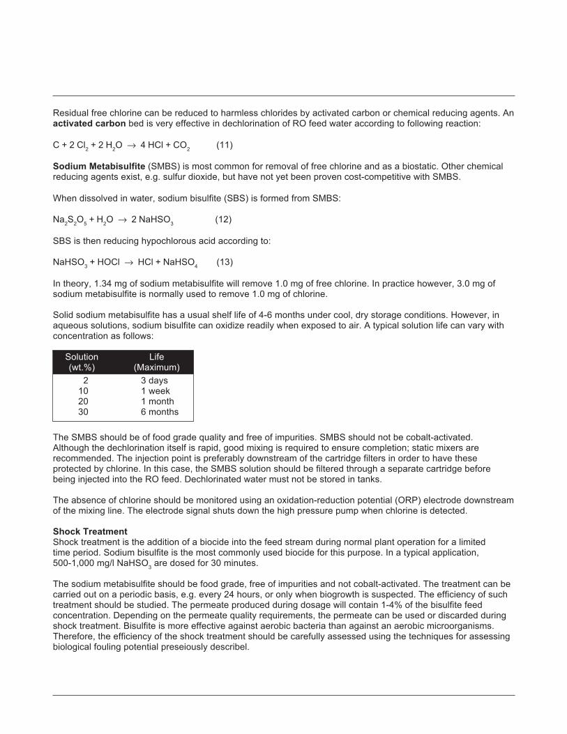
Residual free chlorine can be reduced to harmless chlorides by activated carbon or chemical reducing agents. Anactivated carbon bed is very effective in dechlorination of RO feed water according to following reaction:
C + 2 Cl2 + 2 H2O → 4 HCl + CO2 (11)
Sodium Metabisulfite (SMBS) is most common for removal of free chlorine and as a biostatic. Other chemicalreducing agents exist, e.g. sulfur dioxide, but have not yet been proven cost-competitive with SMBS.
When dissolved in water, sodium bisulfite (SBS) is formed from SMBS:
Na2S2O5 + H2O → 2 NaHSO3 (12)
SBS is then reducing hypochlorous acid according to:
NaHSO3 + HOCl → HCl + NaHSO4 (13)
In theory, 1.34 mg of sodium metabisulfite will remove 1.0 mg of free chlorine. In practice however, 3.0 mg ofsodium metabisulfite is normally used to remove 1.0 mg of chlorine.
Solid sodium metabisulfite has a usual shelf life of 4-6 months under cool, dry storage conditions. However, inaqueous solutions, sodium bisulfite can oxidize readily when exposed to air. A typical solution life can vary withconcentration as follows:
Solution Life(wt.%) (Maximum)
2 3 days10 1 week20 1 month30 6 months
The SMBS should be of food grade quality and free of impurities. SMBS should not be cobalt-activated.Although the dechlorination itself is rapid, good mixing is required to ensure completion; static mixers arerecommended. The injection point is preferably downstream of the cartridge filters in order to have theseprotected by chlorine. In this case, the SMBS solution should be filtered through a separate cartridge beforebeing injected into the RO feed. Dechlorinated water must not be stored in tanks.
The absence of chlorine should be monitored using an oxidation-reduction potential (ORP) electrode downstreamof the mixing line. The electrode signal shuts down the high pressure pump when chlorine is detected.
Shock TreatmentShock treatment is the addition of a biocide into the feed stream during normal plant operation for a limitedtime period. Sodium bisulfite is the most commonly used biocide for this purpose. In a typical application,500-1,000 mg/l NaHSO3 are dosed for 30 minutes.
The sodium metabisulfite should be food grade, free of impurities and not cobalt-activated. The treatment can becarried out on a periodic basis, e.g. every 24 hours, or only when biogrowth is suspected. The efficiency of suchtreatment should be studied. The permeate produced during dosage will contain 1-4% of the bisulfite feedconcentration. Depending on the permeate quality requirements, the permeate can be used or discarded duringshock treatment. Bisulfite is more effective against aerobic bacteria than against an aerobic microorganisms.Therefore, the efficiency of the shock treatment should be carefully assessed using the techniques for assessingbiological fouling potential preseiously describel.
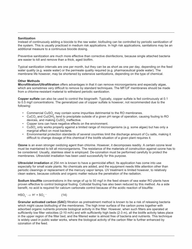
SanitizationInstead of continuously adding a biocide to the raw water, biofouling can be controlled by periodic sanitization ofthe system. This is usually practiced in medium risk applications. In high risk applications, sanitations may be anadditional measure to a continuous biocide dosing.
Preventive sanitization are much more effective than corrective disinfections, because single attached bacteriaare easier to kill and remove than a thick, aged biofilm.
Typical sanitization intervals are one per month, but they can be as short as one per day, depending on the feedwater quality (e.g. waste water) or the permeate quality required (e.g. pharmaceutical grade water). Themembrane life however, may be shortened by extensive sanitizations, depending on the type of chemical.
Other MethodsMicrofiltration/Ultrafiltration offers advantages in that it can remove microorganisms and especially algae,which are sometimes very difficult to remove by standard techniques. The MF/UF membranes should be madefrom a chlorine-resistant material to withstand periodic sanitization.
Copper sulfate can also be used to control the biogrowth. Typically, copper sulfate is fed continuously at 0.1to 0.5 mg/l concentrations. The generalized use of copper sulfate is however, not recommended due to thefollowing:
• Commercial CuSO4 may contain some impurities detrimental to the RO membranes.• CuCO3 and Cu(OH)2 tend to precipitate outside of a given pH range of operation, causing fouling to RO
devices, and making CuSO4 ineffective.• Copper ions can have negative effects on the environment.• CuSO4 only works properly against a limited range of microorganisms (e.g. some algae) but has only a
marginal effect on most bacteria.• Environmental protection standards of several countries limit the discharge amount of Cu salts, making it
difficult to change dosage of this chemical if the biolife situation of a given plant requires it.
Ozone is an even stronger oxidizing agent than chlorine. However, it decomposes readily. A certain ozone levelmust be maintained to kill all microorganisms. The resistance of the materials of construction against ozone has tobe considered. Usually, stainless steel is employed. De-ozonation must be performed carefully to protect themembranes. Ultraviolet irradiation has been used successfully for this purpose.
Ultraviolet irradiation at 254 nm is known to have a germicidal effect. Its application has come into useespecially for small scale plants. No chemicals are added, and the equipment needs little attention other thanperiodic cleanings or replacement of the mercury vapor lamps. UV treatment is limited however, to relativelyclean waters, because colloids and organic matter reduce the penetration of the radiation.
Sodium bisulfite concentrations in the range of up to 50 mg/l in the feed stream of sea water RO plants haveproven effective to control biological fouling. Colloidal fouling has also been reduced by this method. As a sidebenefit, no acid is required for calcium carbonate control because of the acidic reaction of bisulfite:
HSO3– → H+ + SO3
– – (14)
Granular activated carbon (GAC) filtration as pretreatment method is known to be a risk of releasing bacteriawhich might cause biofouling of the membranes. The high inner surface of the carbon pores together withadsorbed organic nutrients promote biological activity in the filter. However, when such filters are operated atsufficiently low filter velocities (2-10 m/h) and with sufficiently high beds (2-3 m), all the biolife activity takes placein the upper region of the filter bed, and the filtered water is almost free of bacteria and nutrients. This techniqueis widely used in public water works, where the biological activity of the carbon filter is further enhanced byozonation of the feed.

The technical information contained here is extracted from the FILMTEC Membranes - Technical Manual. References to other sections of themanual have been replaced with short references to additional but separate information available from our web site. The information in theseextracts has been updated and supercedes that contained in the full manual.Notice: No freedom from any patent owned by Seller or others is to be inferred. Because use conditions and applicable laws may differ from onelocation to another and may change with time, Customer is responsible for determining whether products and the information in this document areappropriate for Customer's use and for ensuring that Customer's workplace and disposal practices are in compliance with applicable laws andother governmental enactments. Seller assumes no obligation or liability for the information in this document. NO WARRANTIES ARE GIVEN;ALL IMPLIED WARRANTIES OF MERCHANTABILITY OR FITNESS FOR A PARTICULAR PURPOSE ARE EXPRESSLY EXCLUDED.Published July 2002.
FILMTEC MembranesFor more information about FILMTEC membranes,call the Dow Liquid Separations business:North America ...................... 1-800-447-4369Latin America ....................... (+55) 11-5188-9277Europe ................................. (+32) 3-450-2240Japan ................................... (+81) 3-5460-2100Australia ............................... (+61) 2-9776-3226http://www.filmtec.com
*Trademark of The Dow Chemical CompanyForm No. 609-00308-702XQRP
The strategy of promoting bioogical growth in a restricted place where it is of no harm to the membranes, ratherthan trying to kill all microorganisms, might be a good approach to control biofouling of the membranes.However, there is little practical experience to date.
To prevent biological fouling of the membranes, the entire system from the raw water intake up to themembranes has to be kept clean and in a sanitary state. Please refer to separate information on Control ofMicrobiological Activity, for more details.

The following tables show the recommended guidelines for designing RO systems with 2.5 and 4-inch FILMTECelements in Light Industrial and Small Commercial applications.
Feed Source RO Well Softened Surface Wastewater (Filtered SeawaterPermeate Water Municipal Municipal Effluent)
MF1 Conventional Well or MF1 Open Intake
Feed Silt Density Index SDI<1 SDI<3 SDI<3 SDI<5 SDI<3 SDI<5 SDI<3 SDI<5
Max. Element Recovery % 30 19 17 15 141 12 13 10
Typical Target Flux, gfd (l/m2h) 22 (37) 18 (30) 16 (27) 14 (24) 13 (22) 11 (19) 13 (22) 11 (19)
Max. Permeate Flow Rate, gpd (m3/d)
2.5-inch Diameter 800 (3.0) 700 (2.6) 600 (2.3) 500 (1.9) 500 (1.9) 400 (1.5) 700 (2.6) 600 (2.3)4.0-inch Diameter 2300 (8.7) 1900 (7.2) 1700 (6.4) 1500 (5.7) 1400 (5.3) 1200 (4.5) 1800 (6.8) 1500 (5.7)
Element Type Min. Concentrate Flow Rate, gpm (m3/h)
2.5-inch Diameter 1 (0.2) 1 (0.2) 1 (0.2) 1 (0.2) 1 (0.2) 1 (0.2) 1 (0.2) 1 (0.2)4.0-inch Diameter (except Full-Fits) 4 (0.9) 4 (0.9) 4 (0.9) 4 (0.9) 5 (1.1) 6 (1.4) 4 (0.9) 5 (1.1)Full-Fit 4040 6 (1.4) 6 (1.4) 6 (1.4) 6 (1.4) 7 (1.6) 8 (1.8) NA NA
FILMTEC MembranesCommercial Design Guidelines for Midsize FILMTECTM Elements
Product Information
Table 1. Design Guidelines for FILMTEC Elements in Light Industrial and Small Sea Water Applications
Element Type Active Area Max. Feed Flow Max. Pressure Drop Maximum Feed Pressureft2 (m2) Rate Per Element psig (bar)
U.S. gpm (m3/h) psig (bar)2
Tape-Wrapped 2540 28 (2.6) 6 (1.4) 13 (0.9) 600 (41)Fiberglassed 2540 28 (2.6) 6 (1.4) 15 (1.0) 600 (41)Seawater 2540 29 (2.7) 6 (1.4) 13 (0.9) 1000 (69)Tape-Wrapped 4040 82 (7.6) 14 (3.2) 13 (0.9) 600 (41)Fiberglassed 4040 82 (7.6) 16 (3.6) 15 (1.0) 600 (41)SW Fiberglassed 4040 80 (7.4) 16 (3.6) 15 (1.0) 1000 (69)Full-Fit 4040 85 (7.9) 18 (4.1) 15 (1.0) 600 (41)
FILMTEC Membranes
*Trademark of The Dow Chemical Company
1 MF: Microfiltration - continuous filtration process using a membrane with pore size of <0.5 micron.
2 We recommend that the pressure drop for new/clean elements be at least 20% below the maximum.
Note: The limiting values listed above have been incorporated into the ROSA (Reverse Osmosis System Analysis) software. Design of systems in excessof the guidelines results in a warning message on the ROSA printout.
Note: System designer must thoroughly review Product Selection Guide before applying above information. For ultrapure applications refer to UPW SystemDesign Guidelines.

The factor which has the greatestinfluence on the membrane systemdesign is the fouling tendency of thefeed water. Membrane fouling iscaused by particles and colloidalmaterial which are present in the feedwater and are concentrated at themembrane surface. The concentrationof the fouling materials at themembrane surface increases withincreasing permeate flux (thepermeate flow rate per unit membrane
area) and increasing FILMTEC elementrecovery (the ratio of permeate flowrate to feed flow rate for a singleelement). A system with high permeateflux rates is, therefore, likely toexperience higher fouling rates andmore frequent chemical cleaning.The Silt Density Index (SDI) value ofthe pretreated feed water correlatesfairly well with the amount of foulingmaterial present.
“Light Industrial” systems in Table 1have the same requirements as forlarge systems, requiring stableperformance over several years. Theyare typically for piloting large systems,with continuous operation, CIPfacilities and none (or minimal)recirculation. The expected membranelifetime is more than 3 years.
Feed Source RO Permeate Softened Municipal Well Water Surface orMunicipal Water
Feed Silt Density Index SDI<1 SDI<3 SDI<3 SDI<5
Max. Element Recovery % 30 30 25 20
Typical Target Flux, gfd (l/m2h) 30 (51) 30 (51) 25 (42) 20 (34)
Max. Permeate Flow Rate, gpd (m3/d)
2.5-inch Diameter 1100 (4.2) 1100 (4.2) 900 (3.4) 700 (2.7)4.0-inch Diameter 3100 (11.7) 3100 (11.7) 2600 (9.8) 2100 (7.9)
Min. Concentrate Flow Rate, U.S. gpm (m3/h) 1
2.5-inch Diameter 0.5 (0.11) 0.5 (0.11) 1 (0.2) 1 (0.2)4.0-inch Diameter 2 (0.5) 2 (0.5) 4 (0.9) 4 (0.9)
Table 2. Design Guidelines for FILMTEC Elements in Small Commercial Applications
Element Type Active Area Max. Feed Flow Max. Pressure Drop Maximum Feed Pressureft2 (m2) Rate Per Element psig (bar)
U.S. gpm (m3/h) psig (bar)3
Tape-Wrapped 2540 28 (2.6) 6 (1.4) 13 (0.9) 600 (41)Fiberglassed 2540 28 (2.6) 6 (1.4) 15 (1.0) 600 (41)Seawater 2540 29 (2.7) 6 (1.4) 13 (0.9) 1000 (69)Tape-Wrapped 4040 82 (7.6) 14 (3.2) 13 (0.9) 600 (41)Fiberglassed 4040 82 (7.6) 16 (3.6) 15 (1.0) 600 (41)SW Fiberglassed 4040 80 (7.4) 16 (3.6) 15 (1.0) 1000 (69)
3 We recommend that the pressure drop for new/clean elements be at least 20% below the maximum.
Note: The limiting values listed above have been incorporated into the ROSA (Reverse Osmosis System Analysis) software. Design of systems in excessof the guidelines results in a warning message on the ROSA printout.
Note: System designer must thoroughly review Product Selection Guide before applying above information. For ultrapure applications refer to UPW SystemDesign Guidelines.

Form No. 609-00374-102QRPCH 172-286-E-102
*Trademark of The Dow Chemical Company
FILMTEC MembranesFor more information about FILMTEC membranes,call Dow Liquid Separations:North America . . . . . . . . . .1-800-447-4369Latin America . . . . . . . . . . .(+55) 11-5188-9345Europe . . . . . . . . . . . . . . .(+32) 3-450-2240Japan . . . . . . . . . . . . . . . .(+81) 3-5460-2100Australia . . . . . . . . . . . . . . .(+61) 2-9776-3226http://www.filmtec.com
Notice: No freedom from any patent owned by Seller or others is to be inferred. Because use conditions and applicable laws may differ from onelocation to another and may change with time, Customer is responsible for determining whether products and the information in this document areappropriate for Customer’s use and for ensuring that Customer’s workplace and disposal practices are in compliance with applicable laws andother governmental enactments. Seller assumes no obligation or liability for the information in this document. NO WARRANTIES ARE GIVEN;ALL IMPLIED WARRANTIES OF MERCHANTABILITY OR FITNESS FOR A PARTICULAR PURPOSE ARE EXPRESSLY EXCLUDED.
Published January 2002.
In Table 2, the “Small Commercial”systems are typically between 1-6elements that are either regularlyreplaced or else cleaned (every halfyear or year) or performance loss isacceptable. The expected elementlifetime is not more than 3 years.This is a low-cost, compact solutionfor intermittently operated systems.
The proposed limits are recommendedguidelines based on many years ofexperience with FILMTEC membranes.If the fouling tendency of the feedwater has been underestimated in thesystem design, the membranes willrequire more frequent cleaning, or thecapacity of the system will decreasedue to fouling. On the other hand, a
conservative approach is toanticipate a higher fouling tendencyand enjoy a troublefree systemoperation and an increasedmembrane lifetime.

Record Keeping
Tech Manual Excerpts
FILMTEC Membranes
FILMTEC Membranes • FilmTec Corporation is a wholly owned subsidiary of The Dow Chemical Company.
*Trademark of The Dow Chemical Company
IntroductionIn order to be able to follow the performance of the RO unit, it is necessary that all relevant data are collected,recorded and kept on file. Apart from keeping track of the performance, the logsheets are also valuable tools fortroubleshooting, and are needed in the cases of warranty claims.
These instructions are for general guidance only and must not be used in place of the operating manual for aparticular plant. Site dependent factors prevent specific recommendations for all record keeping. Thus, only themore general record keeping is covered here.
Start-Up Report• Provide a complete description of the RO plant. This can be done using a flow diagram and equipment,
instrumentation, and material list to show water source, pretreatment system, RO configuration and post-treatment system.
• Give results of checking according to check list (Startup checklist).
• Provide calibration curves of all gauges and meters based on manufacturers' recommendations.
• Record initial performance of RO and pretreatment system as provided below.
RO Operating DataThe following data must be recorded and logged into an appropriate logsheet at least once per shift, unlessotherwise stated (see Table 2 for an example).
• Date, time and hours of operation.
• Pressure drop per cartridge and per stage.
• Feed, permeate and concentrate pressure of each stage.
• Permeate and concentrate flows of each stage.
• Conductivity of the feed, permeate and concentrate streams for each stage. Permeate conductivity of eachpressure vessel weekly.
• TDS of feed, permeate and concentrate streams for each stage. The TDS is calculated from the wateranalysis. It can also be calculated from the conductivity (at 25°C) EC25 and an appropriate K factor:
TDS = K EC25
The K factor has to be determined for each specific stream. Typical K factors are shown in Table 2.
• pH of the feed, permeate and concentrate streams.
• Silt Density Index (SDI) or turbidity of the RO feed stream, or both.
• Water temperature of the feed stream.
• Langelier Saturation Index (LSI) of the concentrate stream from the last stage (for concentrate streams< 10,000 mg/l TDS).
• Stiff and Davis Stability Index (S&DSI) of the concentrate stream from the last stage (for concentratestreams >10,000 mg/l).
• Calibration of all gauges and meters based on manufacturer’s recommendations as to method and frequencybut no less frequent than once every three months.
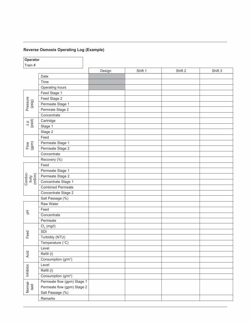
Reverse Osmosis Operating Log (Example)
Operator Train #
Design Shift 1 Shift 2 Shift 3DateTimeOperating hoursFeed Stage 1Feed Stage 2Permeate Stage 1Permrate Stage 2ConcentrateCartridgeStage 1Stage 2FeedPermeate Stage 1Permeate Stage 2ConcentrateRecovery (%)FeedPermeate Stage 1Permeate Stage 2Concentrate Stage 1Combined PermeateConcentrate Stage 2Salt Passage (%)Raw WaterFeedConcentratePermeateCl2 (mg/l)SDITurbidity (NTU)Temperature (°C)LevelRefill (l)Consumption (g/m3)LevelRefill (l)Consumption (g/m3)Permeate flow (gpm) Stage 1Permeate flow (gpm) Stage 2Salt Passage (%)Remarks
Pres
sure
(psi
g)Δ
p(p
sid)
Flow
(gpm
)C
ondu
c-tiv
ity(m
S/m
)
Acid
Inhi
bito
rFe
edpH
Nor
mal
-ise
d

• Any unusual incidents, for example, upsets in SDI, pH and pressure and shutdowns.
• Complete water analysis of the feed, permeate and concentrate streams and the raw water at start-up andevery week thereafter.
The water analysis shall include:
· Calcium
· Magnesium
· Sodium
· Potassium
· Strontium
· Barium
· Iron (total, dissolved and ferrous)
· Aluminium (total and dissolved)
· Bicarbonate
· Sulfate
· Chloride
· Nitrate
· Fluoride
· Phosphate (total)
· Silica (dissolved)
· Total dissolved solids
· Conductivity
· pH
· TOC
1 EC25 does not include the conductivity caused bydissolved CO2
Table 1: Factors for EstimatingTDS from Conductivity
Water EC251 (mS/m) K
Permeate 0.1-1 0.5030-80 0.55
Sea water 4,500-6,000 0.70Concentrate 6,500-8,500 0.75

The technical information contained here is extracted from the FILMTEC Membranes - Technical Manual. References to other sections of themanual have been replaced with short references to additional but separate information available from our web site. The information in theseextracts has been updated and supercedes that contained in the full manual.
Notice: No freedom from any patent owned by Seller or others is to be inferred. Because use conditions and applicable laws may differ from onelocation to another and may change with time, Customer is responsible for determining whether products and the information in this documentare appropriate for Customerís use and for ensuring that Customerís workplace and disposal practices are in compliance with applicablelaws and other governmental enactments. Seller assumes no obligation or liability for the information in this document. NO WARRANTIES AREGIVEN; ALL IMPLIED WARRANTIES OF MERCHANTABILITY OR FITNESS FOR A PARTICULAR PURPOSE ARE EXPRESSLY EXCLUDED.
Published August 2000.
FILMTEC MembranesFor more information about FILMTEC membranes,call Dow Liquid Separations:North America ...................... 1-800-447-4396Latin America ....................... (+55) 11-5188-9277Europe ................................. (+31) 20-691-6268Japan ................................... (+81) 3-5460-2100Australia ............................... (+61) 2-9776-3226http://www.dow.com/liquidseps
*Trademark of The Dow Chemical CompanyForm No. 609-00320-800
CH 172-270-E-800
Pretreatment Operating DataSince the RO system performance depends largely on the proper operation of the pretreatment, the operatingcharacteristics of the pretreatment equipment should be recorded. Specific recommendations for all recordkeeping cannot be given, because pretreatment is site dependent. Typically, the following items must berecorded:
• Total residual chlorine concentration in the RO feed (daily - unless known to be completely absent).
• Discharge pressure of any well or booster pumps (twice a day).
• Pressure drop of all filters (twice a day).
• Consumption of acid and any other chemicals (daily - if used).
• Calibration of all gauges and meters based on manu-facturers' recommendations as to method andfrequency but no less frequent than once every 3 months.
• Any unusual incidents, for example, upsets and shutdowns as they occur.
Maintenance Log• Record routine maintenance.
• Record mechanical failures and replacements.
• Record any change of membrane element locations with element serial numbers.
• Record replacements or additions of RO devices.
• Record calibration of all gauges and meters.
• Record replacement or additions of pretreatment equipment, for example cartridge filters and include date,brand name and nominal rating.
• Record all cleanings of RO membranes. Include date, duration of cleaning, cleaning agent(s) andconcentration, solution pH, temperature during cleaning, flow rate and pressure (for cleaningprocedures see separate information).

Significance and UseDuring the operation of an RO system, system conditions such as pressure, temperature, system recovery and feedconcentration can vary, causing permeate flow and salt passage to change. To effectively evaluate system performance,it is necessary to compare permeate flow and salt passage data at the same conditions. Since data may not always beobtained at the same conditions, it is necessary to convert the RO data obtained at actual conditions to a set of selectedconditions, thereby standardizing the data.
How to use FTNORMIntroductionFTNORM is a spreadsheet-based program designed to standardize the operating data from a reverse osmosis ornanofiltration system using FILMTECTM membranes. This program is based on the use of Microsoft Excel and providesfor automatic standardization of operating data. Charts are created showing standardized permeate flow, standardizedsalt passage/salt rejection and differential pressure (ΔP). You should use one spreadsheet for each train in the system.
Entering Data1. From within Microsoft Excel, open the file containing the data standardization template, Data Normalization Template
(System or One Stage). All of the cells requiring data entry contain red lettering. Blue lettering is used for calculatedvalues. You can choose to enter the data in U.S. units or in metric units.
2. At the top of the spreadsheet, enter the “plant identification” and “start-up date” in the designated cells.
3. The operating data is entered beginning in row 11 with the date. You will overwrite the existing sample data, which ispresent. The equations performing the standardization calculations will allow approximately one year (365 days) ofdata entry. You will need to copy the equations for each column when additional operating data is entered.
4. When you have completed entering data, save the spreadsheet using a unique name associated with the train.
Graphing DataThe charts contained in the template are designed to show the first five data points in cells 11 through 15. As additionaldata is entered you must update the chart using the chart\source data portion of the menu. In this section, you willincrease the maximum values for the X-axis and Y-axis to reflect the operating data entered. When you do so the chartwill update to include the new data.
FILMTEC Membranes
Tech Facts
*Trademark of The Dow Chemical Company
FILMTEC Membranes
Standardizing Reverse Osmosis Performance Data
Form No. 609-00313-402XQRPCH 172-263-E-402R

*Trademark of The Dow Chemical Company
FILMTEC MembranesFor more information about FILMTEC membranes, call the Dow Liquid Separations business:North America . . . . . . . . . . .1-800-447-4369Latin America . . . . . . . . . . .(+55) 11-5188-9277Europe . . . . . . . . . . . . . . . .(+32) 3-450-2240Japan . . . . . . . . . . . . . . . . .(+81) 3-5460-2100Australia . . . . . . . . . . . . . . .(+61) 2-9776-3226http://www.filmtec.com
NOTICE: No freedom from any patent owned by Seller or others is to be inferred. Because use conditions and applicable laws may differ fromone location to another and may change with time, Customer is responsible for determining whether products and the information in thisdocument are appropriate for Customer’s use and for ensuring that Customer’s workplace and disposal practices are in compliance withapplicable laws and other governmental enactments. Seller assumes no obligation or liability for the information in this document. NOWARRANTIES ARE GIVEN; ALL IMPLIED WARRANTIES OF MERCHANTABILITY OR FITNESS FOR A PARTICULAR PURPOSE AREEXPRESSLY EXCLUDED.
Published April 2002.
Form No. 609-00313-402XQRPCH 172-263-E-402R

Scale Control
Tech Manual Excerpts
FILMTEC Membranes
FILMTEC Membranes • FilmTec Corporation is a wholly owned subsidiary of The Dow Chemical Company.
*Trademark of The Dow Chemical Company
Table 1: Solubility Products of Sparingly Soluble Inorganic Compounds1
Substance Formula Temp. Solubility Negative°C Product Log K
Aluminium Hydroxide Al(OH)3 20 1.9 x 10⁻³³ 32.7Barium Carbonate BaCO3 16 7 x 10⁻⁹ 8.15Barium Sulfate BaSO4 25 1.08 x 10⁻¹⁰ 9.97Calcium Carbonate CaCO3 25 8.7 x 10⁻⁹ 8.06Calcium Fluoride CaF2 26 3.95 x 10⁻¹¹ 10.61Calcium Sulfate CaSO4 10 6.1 x 10⁻⁵ 4.21Cupric Sulfide CuS 18 8.5 x 10-45 44.07Ferric Hydroxide Fe(OH)3 18 1.1 x 10-36 35.96Ferrous Hydroxide Fe(OH)2 18 1.64 x 10⁻¹⁴ 13.78Lead Carbonate PbCO3 18 3.3 x 10⁻¹⁴ 13.48Lead Fluoride PbF2 18 3.2 x 10⁻⁶ 7.50Lead Sulfate PbSO4 18 1.06 x 10⁻⁸ 7.98Magnesium AmmoniumPhosphate MgNH4PO4 25 2.5 x 10⁻¹³ 12.6Magnesium Carbonate MgCO3 12 2.6 x 10⁻⁵ 4.58Magnesium Hydroxide Mg(OH)2 18 1.2 x 10⁻¹¹ 10.92Manganese Hydroxide Mn(OH)2 18 4 x 10-14 13.4Nickel Sulfide NiS 18 1.4 x 10⁻²⁴ 23.85Strontium Carbonate SrCO3 25 1.6 x 10⁻⁹ 8.80Strontium Sulfate SrSO4 17.4 2.81 x 10⁻⁷ 6.55Zinc Hydroxide Zn(OH)2 20 1.8 x 10⁻¹⁴ 13.74
1 At zero ionic strength
IntroductionScaling of a reverse osmosis membrane may occur when sparingly soluble salts are concentrated within theelement beyond their solubility limit. For example, if a reverse osmosis plant is operated at 50% recovery, theconcentration in the concentrate stream will be double the concentration in the feed stream. As the recovery ofa plant is increased, so is the risk of scaling.Therefore, care must be taken not to exceed the solubility limitsof slightly soluble salts, or precipitation and scaling may occur.
In a reverse osmosis system the most common sparingly soluble salts encountered are CaSO4, CaCO3 andsilica. Other salts creating a potential scaling problem are CaF2, BaSO4 and SrSO4. Solubility products ofsparingly soluble inorganic compounds are listed in Table 1.
In order to prevent scaling of a reverse osmosis membrane the following design practices are possible.
Acid AdditionMost natural surface and ground waters are almost saturated with respect to CaCO3. The solubility of CaCO3depends on the pH, as can be seen from the following equation:Ca++ + HCO3
– ↔ H+ + CaCO3 (1)
Accordingly, by adding H+ as acid, the equilibrium can be shifted to the left side in order to keep calciumcarbonate dissolved. The acid used should be of food grade quality.

Sulfuric acid is easier to handle and in many countries more readily available than hydrochloric acid, but on theother hand, additional sulfate is added to the feed stream. This might be critical with respect to sulfate scaling.
In order to avoid calcium carbonate scaling, CaCO3 should tend to dissolve in the concentrate stream rather thanto precipitate. This tendency can be expressed by the Langelier Saturation Index (LSI) for brackish waters andthe Stiff & Davis Stability Index (S&DSI) for sea waters. At the pH of saturation (pHS), the water is in equilibriumwith CaCO3. The definitions of LSI and S&DSI are:LSI = pH - pHS (TDS <10,000 mg/l) (2)S&DSI = pH - pHS (TDS >10,000mg/l) (3)
To control calcium carbonate scaling by acid addition alone, the LSI or S&DSI in the concentrate stream must benegative. If a high quality scale inhibitor is used, the LSI in the concentrate stream can be < 1.5. This will reduceor eliminate the acid consumption. Many inhibitors allow operation up to an LSI of < 1.8 in the concentrate.Please refer to the inhibitor manufacturer’s own literature for reference points.
Scale Inhibitor AdditionScale inhibitors (antiscalants) can be used to control carbonate scaling, sulfate scaling and calcium fluoridescaling. Scale inhibitors have a “threshold effect”, which means that minor amounts adsorb specifically to thesurface of microcrystals thereby preventing further growth and precipitation of the crystals.
The most widely used scale inhibitor is sodiumhexametaphosphate (SHMP). Food grade quality should be used.Care has to be taken in order to avoid hydrolysis of SHMP in the dosing feed tank. Hydrolysis would not onlydecrease the scale inhibition efficiency, but also create a calcium phosphate scaling risk. SHMP should be dosedto give a concentration in the concentrate stream of 20 mg/l. For example, the dosage into the feed stream of asystem with 75% recovery will be 5 mg/l.
Polymeric organic scale inhibitors are more effective than SHMP. However, precipitation reactions may occurwith cationic polyelectrolytes or multivalent cations, e.g. aluminium or iron. The resulting gumlike products arevery difficult to remove from the membrane elements.
For dosage rates please contact the antiscalant manufacturers. Overdosing should be avoided. In RO plantsoperating on sea water with TDS in the range of 35,000 mg/l, scaling is not such a problem as in brackish waterplants, because the recovery of sea water plants is limited by the osmotic pressure of the concentrate stream to30-45%. However, for safety reasons we recommend using a scale inhibitor when operating above a recovery of35%.
Softening with a Strong Acid Cation Exchange ResinThe scale forming cations such as Ca++, Ba++, Sr++ are removed and replaced by sodium cations. The resin has tobe regenerated with NaCl at hardness breakthrough. The pH of the feed water is not changed by this treatment.Therefore, no degassifier is needed. Only a little CO2 from the raw water is present that can pass into thepermeate creating a conductivity increase there. One can even lower the permeate conductivity by adding someNaOH to the softened feed water (up to pH 8.2) in order to convert residual carbon dioxide into bicarbonate whichis then rejected by the membrane. The rejection performance of the FT30 membrane is optimal at the neutralpH range.
With DOWEX* ion exchange resins, the removal efficiency for Ca++, Ba++ and Sr++ is > 99.5%, which usuallyeliminates any risk of carbonate or sulfate scaling. Softening with a strong acid cation exchange resin is veryeffective and safe, provided the regeneration is done properly. It is used mainly in small or medium size brackishwater plants, but not in sea water plants.
A drawback of this process is its relatively high sodium chloride consumption, which might cause anenvironmental or an economic problem. With DOWEX* MONOSPHERE* ion exchange resins and acountercurrent regeneration technique, for example UPCORE*, it is possible to minimize the sodium chlorideconsumption to 110% of the stoichiometrical value.

Dealkalization with a Weak Acid Cation Exchange ResinDealkalization with a weak acid cation exchange resin is used mainly in large brackish water plants for partialsoftening in order to minimize the consumption of regeneration chemicals.
In this process, only Ca++, Ba++ and Sr++ linked to bicarbonate (temporary hardness) are removed and replaced byH+, thus lowering the pH to 4-5. As the acidic groups of the resin are carboxylic groups, the ion exchange processstops when the pH reaches a value of 4.2, where the carboxylic groups are no longer dissociated. Therefore, it isonly a partial softening. Only those scale forming cations are removed which are bound to bicarbonate.Therefore, this process is ideal for waters with a high bicarbonate content. The bicarbonate is converted intocarbon dioxide:HCO3
– + H+ ↔ H2O + CO2 (4)
In most cases, carbon dioxide is not desired in the permeate. It can be removed by degassing either in thepermeate or in the feed stream.
Degassing the permeate is favored where a potential for biofouling is suspected (surface waters, high TOC,high bacteria counts). A high CO2 concentration on the membranes helps to keep bacteria growth low. Degassingthe feed is preferred when optimum salt rejection is the priority. Removing CO2 also leads to an increase in pH(see equation (4)), and at pH > 6 the rejection is better than at pH < 5.
The advantages of dealkalizing with a weak acid cation exchange resin are:• For regeneration, acid of not more than 105% of the stoichiometrical value is needed. This minimizes the
operating costs and the environmental impact.• The TDS value of the water is reduced by the removal of bicarbonate salts. Accordingly, the permeate
TDS value is also lower.
The disadvantages are:• Residual hardness.
If a complete softening is required, a sodium exchange process with a strong acid cation exchange resincan be added, even in one vessel. The overall consumption of regeneration chemicals is still lower thansoftening with a strong acid cation exchange resin alone. Due to the higher investment costs however, thiscombination will only be attractive for plants with high capacity.Another possibility to overcome this drawback of incomplete softening is to dose an antiscalant into thedealkalized water. Although we have so far never encountered scaling problems with waters dealkalized byweak acid cation exchange alone, we strongly recommend to calculate the solubilities of the residual spa-ringly soluble salts and to take the respective measures.
• Variable pH of the treated water.The pH of the dealkalized water ranges from 3.5 to 6.5 depending on the degree of exhaustion of the resin.This cyclic pH variation makes it difficult to control the salt rejection of the plant. At pH < 4.2, the passageof mineral acid may increase the permeate TDS. It is therefore recommended to use more than one filter inparallel and to regenerate them at different times in order to level out the pH. Other possibilities to avoidextremely low pH values are CO2 removal or pH adjustment by NaOH afterwards.
Lime SofteningLime softening can be used to remove carbonate hardness by adding hydrated lime:Ca(HCO3)2 + Ca(OH)2 → 2 CaCO3 + 2 H2O (5)Mg(HCO3)2 + 2 Ca (OH)2 → Mg(OH)2 + 2 CaCO3 + 2H2O (6)
The noncarbonate calcium hardness can be further reduced by adding sodium carbonate (soda ash):CaCl2 + Na2CO3 → 2 NaCl + CaCO3 (7)
The lime-soda ash process can also be used to reduce the silica concentration. When sodium aluminate andferric chloride are added, the precipitate will include calcium carbonate and a complex with silicic acid, aluminiumoxide and iron. With the hot lime silicic acid removal process at 60-70°C, silica can be reduced to 1 mg/l byadding a mixture of lime and porous magnesium oxide.

The technical information contained here is extracted from the FILMTEC Membranes - Technical Manual. References to other sections of themanual have been replaced with short references to additional but separate information available from our web site. The information in theseextracts has been updated and supercedes that contained in the full manual.
Notice: No freedom from any patent owned by Seller or others is to be inferred. Because use conditions and applicable laws may differ from onelocation to another and may change with time, Customer is responsible for determining whether products and the information in this documentare appropriate for Customerís use and for ensuring that Customerís workplace and disposal practices are in compliance with applicablelaws and other governmental enactments. Seller assumes no obligation or liability for the information in this document. NO WARRANTIES AREGIVEN; ALL IMPLIED WARRANTIES OF MERCHANTABILITY OR FITNESS FOR A PARTICULAR PURPOSE ARE EXPRESSLY EXCLUDED.
Published August 2000.
FILMTEC MembranesFor more information about FILMTEC membranes,call Dow Liquid Separations:North America ...................... 1-800-447-4396Latin America ....................... (+55) 11-5188-9277Europe ................................. (+31) 20-691-6268Japan ................................... (+81) 3-5460-2100Australia ............................... (+61) 2-9776-3226http://www.dow.com/liquidseps
*Trademark of The Dow Chemical CompanyForm No. 609-00306-800
CH 172-256-E-800
With lime softening, barium, strontium and organic substances are also reduced significantly. The processrequires a reactor with a high concentration of precipitated particles serving as crystallization nuclei. This isusually achieved by upflow solids-contact clarifiers. The effluent from this process needs media filtration andpH adjustment prior to the RO elements. Iron coagulants with or without poly-meric flocculants (anionic and non-ionic) may be used to improve the solid-liquid separation.Lime softening should be considered for brackish water plants larger than 200 m3/h (880 gpm). More details aredescribed in the literature.
Preventative CleaningIn some applications, scaling is controlled by preventive membrane cleaning. This allows the system to runwithout softening or dosage of chemicals. Typically, those systems operate at low recovery in the range of 25%,and the membrane elements are replaced after 1-2 years. Accordingly, those systems are mainly small single-element plants for potable water from tap water or sea water. The simplest way of cleaning is a forward flush atlow pressure by opening the concentrate valve. Short cleaning intervals are more effective than long cleaningtimes, e.g. 30 seconds every 30 minutes.Cleaning can also be carried out with cleaning chemicals. In batch processes like in waste water treatment it iscommon practice to clean the membranes after every batch.The cleaning procedure, cleaning chemicals and the frequency of cleaning, has to be determined and optimizedcase by case. Special care has to be taken not to allow a scaling layer to develop in the course of time.
Adjustment of Operating VariablesWhen other scale control methods do not work, the operating variables of the plant have to be adjusted in such away that scaling will not occur. The precipitation of dissolved salts can be avoided by keeping their concentrationbelow the solubility limit, that means by reducing the system recovery until the concentrate concentration is lowenough.Solubility depends also on temperature and pH. In the case of silica, increasing temperature and pH increases itssolubility. Silica is usually the only reason for considering adjustment of operating variables as a scale controlmethod, because these adjustments have economic drawbacks (energy consumption) or other scaling risks(CaCO3 at high pH).For small systems, a low recovery combined with a preventive cleaning program might be a convenient way tocontrol scaling.

A RO system is designed to be operated continuously. However, in reality RO systems will start-up and shutdown onsome frequency. When the RO membrane system is shutdown, the system must be flushed with either permeate wateror high quality feedwater, to remove the high salt concentration from the modules until concentrate conductivity matchesfeedwater conductivity. Flushing is done at low pressure (about 3 bar/40 PSI). A high feed flow rate is beneficial for acleaning effect; however, a pressure drop of 1.0 bar (15 PSI) per element or 3.5 bar (50 PSI) per multi-element vesselmust not be exceeded.
The water used for flushing shall contain no chemicals used for the pretreatment. Therefore, any chemical injection isstopped before flushing the system. After flushing the system, the feed valves are closed completely. If the concentrateline ends into a drain below the level of the pressure vessels, then an air break should be employed in the concentrateline at a position higher than the highest pressure vessel. Otherwise, the vessels might be emptied by a siphoning effect.
When the system must be shutdown for longer than 48 hours, take care that:• The elements do not dry out. Dry elements will irreversibly lose flux.• The system is adequately protected against micro-biological growth, or regular flushing is carried out every 24 hours.• When applicable, the system is protected against temperature extremes.
The RO train can be stopped for 24 hours without preservation and precautions for microbiological fouling. If feedwaterfor flushing every 24 hours is not available, preservation with chemicals is necessary for longer stops than 48 hours.
Depending on the previous operational history of the plant, it will be necessary in almost all cases to perform a cleaningof the RO membranes prior to preservation. This is especially applicable when the membranes are known or assumed tobe fouled. A typical sequence for the cleaning can be as follows:
Perform a soft alkaline cleaning at pH=11 for 2 hours, disinfect and perform a short acid cleaning. If the plant has beenoperated with a feedwater which is free of scalants and metal hydroxides, the acid cleaning can be omitted.
After cleaning and disinfection, the preservation should follow within the next 10 hours as follows:1. Preservation of the plant using “total immersion” of elements into a solution of 1 to 1.5% of sodium bisulfite (SBS),
venting the air outside of the pressure vessels. Use the overflow technique: circulate the SBS solution in such a waythat the remaining air in the system is minimized after the recirculation is completed. The SBS solution shall beallowed to overflow through an opening located higher than the upper end of the highest pressure vessel being filledin order to ensure all of the air has been eliminated.
2. Separate the preservation solution from the air outside by closing all valves. Any contact with oxygen will oxidize theSBS.
3. Check the pH once a week. When the pH becomes 3 or lower, change the preservation solution.4. Change the preservation solution at least once a month.
During the shutdown period, the plant must be kept frost-free, and the temperature must not exceed 45°C (113°F). A lowtemperature is desirable.
For additional information, please refer to the product information bulletin entitled FT30 Reverse Osmosis MembraneBiological Protection and Disinfection, Form No. 609-24010/172-120-E.
FILMTEC Membranes
Tech Facts
*Trademark of The Dow Chemical Company
RO Systems Shutdown and Lay-up Considerations
FILMTEC™ Membranes Form No. 609-00238-402XQRPCH 172-202-E-402R

*Trademark of The Dow Chemical Company
FILMTEC MembranesFor more information about FILMTEC membranes, call the Dow Liquid Separations business:North America . . . . . . . . . . .1-800-447-4369Latin America . . . . . . . . . . .(+55) 11-5188-9277Europe . . . . . . . . . . . . . . . .(+32) 3-450-2240Japan . . . . . . . . . . . . . . . . .(+81) 3-5460-2100Australia . . . . . . . . . . . . . . .(+61) 2-9776-3226http://www.filmtec.com
Notice: No freedom from any patent owned by Seller or others is to be inferred. Because use conditions and applicable laws may differ from onelocation to another and may change with time, Customer is responsible for determining whether products and the information in this document areappropriate for Customer’s use and for ensuring that Customer’s workplace and disposal practices are in compliance with applicable laws and othergovernmental enactments. Seller assumes no obligation or liability for the information in this document. NO WARRANTIES ARE GIVEN;ALL IMPLIED WARRANTIES OF MERCHANTABILITY OR FITNESS FOR A PARTICULAR PURPOSE ARE EXPRESSLY EXCLUDED.
Published April 2002.
Form No. 609-00238-402XQRPCH 172-202-E-402R

Initial Start-Up
Pre-Start-Up Checklist
❒ Corrosion resistant materials of construction are used for all equipment including piping and wetted parts of pumps
❒ All piping and equipment is compatible with designed pressure
❒ All piping and equipment is compatible with designed pH range (including cleaning)
❒ All piping and equipment is protected against galvanic corrosion
❒ Media filters are backwashed and rinsed
❒ New/clean cartridge filter is installed directly upstream of the high pressure pump
❒ Feed line, including RO feed manifold, is purged and flushed, before pressure vessels are connected
❒ Chemical addition points are properly located
❒ Check valves are properly installed in chemical addition lines
❒ Provisions exist for proper mixing of chemicals in the feed stream
❒ Provisions exist for preventing the RO system from operating when the dosage pumps are shut down
❒ Provisions exist for preventing the dosage pumps from operating when the RO system is shut down
❒ If chlorine is used, provisions exist to ensure complete chlorine removal prior to the membranes
❒ Planned instrumentation allows proper operation and monitoring of the pretreatment and RO system
❒ Planned instrumentation is installed
❒ Instrumentation is calibrated
❒ Pressure relief protection is installed and correctly set
❒ Provisions exist for preventing the product pressure from exceeding the feed/brine pressure more than 0.3 bar(5 PSI) at any time
❒ Interlocks, time delay relays and alarms are properly set
❒ Provisions exist for sampling permeate from individual modules
❒ Provisions exist for sampling feed, permeate and reject streams from each stage and the total plant permeatestream
❒ Pressure vessels are properly piped both for operation and cleaning mode
❒ Pressure vessels are secured to the rack or frame
❒ Precautions are taken as given in pressure vessel manufacturers information on Assembly and Loading ofPressure Vessels
❒ Membranes are protected from temperature extremes (freezing, direct sunlight, heater exhaust, etc.)
❒ Pumps are ready for operation (lubricated, proper rotation)
❒ Fittings are tight
❒ Permeate line is open
❒ Permeate flow is directed to drain
❒ Reject flow control valve is in open position
❒ Feed flow valve is throttled and/or pump bypass valve is partly open to limit feed flow to less than 50 % of operatingfeed flow
Tech Manual Excerpts
FILMTEC Membranes
FILMTEC Membranes • FilmTec Corporation is a wholly owned subsidiary of The Dow Chemical Company.
*Trademark of The Dow Chemical Company

The technical information contained here is extracted from the FILMTEC Membranes - Technical Manual. References to other sections of themanual have been replaced with short references to additional but separate information available from our web site. The information in theseextracts has been updated and supercedes that contained in the full manual.
Notice: No freedom from any patent owned by Seller or others is to be inferred. Because use conditions and applicable laws may differ from onelocation to another and may change with time, Customer is responsible for determining whether products and the information in this documentare appropriate for Customerís use and for ensuring that Customerís workplace and disposal practices are in compliance with applicablelaws and other governmental enactments. Seller assumes no obligation or liability for the information in this document. NO WARRANTIES AREGIVEN; ALL IMPLIED WARRANTIES OF MERCHANTABILITY OR FITNESS FOR A PARTICULAR PURPOSE ARE EXPRESSLY EXCLUDED.
Published April 2000.
FILMTEC MembranesFor more information about FILMTEC membranes,call Dow Liquid Separations:
North America ...................... 1-800-447-4396Latin America ....................... (+55) 11-5188-9277Europe ................................. (+31) 20-691-6268Japan ................................... (+81) 3-5460-2100Australia ............................... (+61) 2-9776-3226http://www.dow.com/liquidseps
*Trademark of The Dow Chemical CompanyForm No. 609-00297-400
CH 172-247-E-400

When considering the design and purchase of large membrane systems, there are a number of possible equipmentdesigns and additions that can be added to help with future troubleshooting. Depending on the size and complexity of thesystem, some or all of these suggestions could be discussed with your system supplier. None are required for successfuloperation, but all make day-to-day operation and troubleshooting easier, quicker and more effective.
Access to Load and Troubleshoot the SystemEven though membrane systems are quite compact, there is often a temptation to save even more floor space bycrowding equipment, pipelines and supports so close together as to limit access to the membrane system. Ideally, oneshould have unrestricted access to both the feed and brine end of each and every vessel for loading, unloading andtroubleshooting of the membrane elements. When loading, at least the length of one element is necessary between thefeed end of the vessels and the nearest equipment or supports. When unloading, often more room could be used so thata large wooden board or some other device can be used to push the element stack toward the brine end.
Connections Allowing Probing, Profiling and SamplingWhen troubleshooting potential element problems, one of the first operations is always to attempt to localize any problem,either to a stage, a vessel, or even an element. Having sample points on all the vessel permeates greatly facilitates theseoperations. Ideally, the permeate sample points can allow a probe tube to be passed through. Having additional samplepoints on the feed, the concentrate and any interstage headers, can help localize problems to a stage and even allow formass balance measurements to corroborate flow measurements and ultimately setting of the system recovery.
Instrumentation to Allow Performance Monitoring by StageBeyond simple sample points, the next step in system sophistication is to instrument the stages so that performance datacan be gathered and normalized, showing day to day variation in the system performance against a reference conditionsuch as startup. Adequate instrumentation means having conductivity or TDS measurements, pressure measurements,temperature measurements and flow measurements on the feed, concentrate and permeate of each stage. Given thisdata, performance of the stage can be monitored and early signs of trouble can be easily detected from the normalizeddata. Even though a mass balance around the system can be used to eliminate some of the instrumentation, having allthe instrumentation means that the mass balance can be used to test the internal consistency of the data and thusmonitor the performance of the instruments.
Real-Time Online NormalizationIn terms of system monitoring, online instruments feeding an ongoing and continuous normalization program is theultimate. For very large systems, or for systems with highly variable feed conditions, real-time control may be warranted.
Provisions to Clean Each Stage IndividuallyMany large systems are provided with so called clean in place systems (CIP). One design suggestion to consider is thatby providing sufficient piping and valving to clean each stage of a system individually will invariably make the cleaningsmore effective. Cleaning multiple stages together means that dirt, debris, bio-mass and scale must be pushed from thefirst stage and through subsequent stages before being removed from the system. CIP systems should also provideadequate flow rates for effective cleanings as well as facilities to heat the cleaning solutions.
Permeate Flushing CapabilityA potential system feature that can lower the frequency of cleanings is to provide for periodic permeate flushing of thesystem. Permeate flushing is accomplished by recycling permeate or product water through the system at a high rate toloosen and push out foulant layers before they adhere to the membrane surface. This capability is especially useful insystems handling treated waste water.
FILMTEC Membranes
Tech Facts
*Trademark of The Dow Chemical Company
FILMTECTM Membranes
System Design Suggestions for Troubleshooting Success
Form No. 609-00318-402XQRPCH 172-268-E-402R

*Trademark of The Dow Chemical Company
FILMTEC MembranesFor more information about FILMTEC membranes, call the Dow Liquid Separations business:North America . . . . . . . . . . .1-800-447-4369Latin America . . . . . . . . . . .(+55) 11-5188-9277Europe . . . . . . . . . . . . . . . .(+32) 3-450-2240Japan . . . . . . . . . . . . . . . . .(+81) 3-5460-2100Australia . . . . . . . . . . . . . . .(+61) 2-9776-3226http://www.filmtec.com
NOTICE: No freedom from any patent owned by Seller or others is to be inferred. Because use conditions and applicable laws may differ fromone location to another and may change with time, Customer is responsible for determining whether products and the information in thisdocument are appropriate for Customer’s use and for ensuring that Customer’s workplace and disposal practices are in compliance withapplicable laws and other governmental enactments. Seller assumes no obligation or liability for the information in this document. NOWARRANTIES ARE GIVEN; ALL IMPLIED WARRANTIES OF MERCHANTABILITY OR FITNESS FOR A PARTICULAR PURPOSE AREEXPRESSLY EXCLUDED.
Published April 2002.
Form No. 609-00318-402XQRPCH 172-268-E-402R
SDI Measurement Device and Connection Points in the SystemA great diagnostic tool especially for the pretreatment end of a system is having and using an SDI instrument. Likeprofiling and probing the elements can localize a potential membrane problem, and SDI instrument with connectionsthroughout the pretreatment system can help quickly localize pretreatment problems.
Wet Lab at the Plant SiteHaving the capability to do laboratory work at the plant site means that water analyses can be more easily monitored,especially for setting up and maintaining pretreatment chemical additions.
Single Element Test UnitHaving a single element test unit at the plant can be a real advantage. Suspect membrane elements be quickly testedand judged good or bad. In addition, cleaning strategies can be tested and proven on fouled elements before tried onwhole stages of the plant.