fillunger all product booklet 2014
TRANSCRIPT

PROFILE

Team FillungerH. Fillunger was established in the year 1926 as a Trading Company by Dr. Harry Fillunger (a German), Mr. Stracatti (a Czech) and Mr. D. A. Marathe (an Indian), as a partnership Company and was incorporated as a Private Ltd., in the year 1957. Fillunger has three main business activities namely LPG Division, Vacuum Division & Agency Division.
Under LPG Division (Formerly known as Chinchwad Precision Optical Frame Works), initially company manufactured precision screws for cameras & scientific instru-ments and precision turned components for LPG regulators & valves. Presently LPG division manufactures LPG Regulators for Domestic Gas Applications, Adaptors / Couplings and Valve Components. This Division has around 100% Export to European Countries and also to some South East Asian Countries.
Our Agency Division represents world renowned manufacturers / suppliers of various industrial raw materials, components and equipment. Some of our principles from their specialized field are:Raw Material: Coroplast Fritz Mueller GmbH Germany, Tadiran Batteries Limited, Israel, Goodfellow Cambridge Ltd, UK etc. Equipment: SVCS Process Innovation s.r.o, Czech Republic, TPT Wire Bonders, Germany, Disco Hi-tec Pte Ltd., Singapore, Roth & Rau AG, Germany etc. Components: SPT Asia Pte. Ltd., Singapore, Tanaka Kikinzoku Group, Japan etc.
Mandar A. MaratheManaging Director
Fillunger’s Vacuum Division (formerly known as The New Poona Industries) launched its first product in 1959. In 1987, Vacuum Division diversified & started manufacturing high & ultra-high vacuum components as an import substitution. The users for these products are scientific community in India and various research establishments like Department of Atomic Energy, Nuclear Power Corporation of India Limited, Defense Labs, CSIR Labs, Department of Space, IIT’s and Universities. Presently Vacuum Division has all the facilities including conventional machine, CNC, machine tools, Modern Welding Machines, 3D & 2D design packages in Engineering, a well-equipped test laboratory to ensure flawless quality product. The manufacturing plant & sales is located in Pune & sales representatives in Mumbai, Delhi, Chennai, Bangalore & Kolkata.
Fillunger Vacuum Division Manufactures
Standard Vacuum Components Motion Manipulation Vacuum Valves Custom Built High and Ultra High Vacuum Chambers Helium Mass Spectrometer Leak Detectors Plasma Cleaning Systems Reactive Ion Etching Systems Magnetron Sputter Deposition SystemsNanoparticle Deposition SystemsThermal Coating Systems Vacuum based high temperature substrate heating/annealing systems Atmospheric Pressure Plasma Jet
H. Fillunger Vacuum Division has several reputed domestic and international clients involved in research activities in the field of particle accelerator beam lines, Surface Science Studies, Thin Film Studies, Electron Microscopy Specimen Preparation as well as production oriented customers in the field of Automotive , Plastics, Semiconductors, Non-destructive Testing for Petroleum / Petrochemical Industry, Hermetically Sealed Electronic Components, Heat Exchangers, Vacuum Interrupters / Switchgears & other applications involving non-destructive testing using Helium Leak Detectors.
QUALITY POLICY We satisfy our customer by delivering right product & right service at right time. We work as a team and improve our products & services continually.

For removing hydrocarbon contamination from specimen and holders prior to electron microscopy analysis
APPLICATIONS:l Cleaning of Surface (e.g. cleaning of SEM and TEM specimen holders and specimen itself)l Activation of surfaces (e.g. before printing, varnishing or gluing)l Plasma Polymerization (e.g. depositing polymer films from liquid/ gaseous monomer)
EM-PC-1000-BasicPLASMA CLEANER
A Plasma technique is now being implemented in the field of electron microscopy, where specimens can become contaminat-ed during the preparation process or from other sources. Current analytical instruments use tightly focused, intense beams that create carbon deposits on the specimen surface due to organic contamination. The EM-PC-1000-Basic plasma cleaner is designed to simultaneously clean the specimen and specimen stage, which minimizes, and in many cases, eliminates contamination of the specimen being analyzed. The specimen holder and specimen are subjected to reactive gas plasma prior to electron microscopy analysis (SEM and TEM).
TECHNICAL DATA
CONTROL PANEL Readouts Readouts Analog display indicates forward power and reflected power in WattsForward Power Control 0-100 Watts , AdjustableElectronics RF Generator (13.56 MHz) with manual 50 Ohm impedance matching network (Automatic
impedance matching optionally available)Interlocks RF, Gas and Vacuum fully interlocked for users & lab safetyProcess Time Process time can be manually set via timer, based on the specimen material properties &
applications
POWER INPUT 230 VAC single phase, 50 Hz, 15 A
VACUUM SYSTEM Pump 60 Ltr/Sec Turbo Molecular Pump with a 4.8m3 /h Rotary Pump
(Dry Scroll Pump optionally available) Base Pressure 1 x 10⁻⁵ mbarOperating Pressure User Variable (0.05 torr upto 0.5 torr typical)System Vacuum vent Independent Solenoid operated Vent ValvePressure Control Pressure Control is done using manual Right angle valve with fully closed position sensor
interlocked with system vent
GAS INLETS Manually adjustable gas flow through two Rotameters for two of either Argon/Oxygen/Air
CHAMBERSize 200 mm x 100 mm High Stainless steel electro-polished cylinder with view port Electrode Immersed stainless steelSpecimen Interface “No Tools” quick connect for all side and top entry holders
SAMPLE HANDLING Standard Electron Microscopy holder for TEM applications. Special Stainless Steel trays for accommodating SEM samples or larger samples of 4” dia.
ACCESSORIES Quick connect TEM specimen holder adaptors, Vacuum Storage Chamber for storing SEM and TEM specimen, Disc Punch TEM-DP-100 for punching TEM Discs
MACHINE FOOTPRINT H 510mm x W 550mm x D 500mm
DISC PUNCH TEM-DP-100 The Disc Punch prepares specimen discs of 3 mm diameter and thickness ranging from 10 micron to above 100 micron for transmission electron microscopy (TEM). The model TEM-DP-100 Disc Punch is designed to prepare ductile metals and soft materials for TEM without mechanical distortion. Solid constructions and high tolerance design allows maximum force to be used with difficult materials while maintaining specimen quality. The construction of the disc punch is such that one can easily select the position to be punched. A small removable tray simplifies collection of punched discs. The mechanical layout ensures a uniform application of pressure on to the specimen. A strong metal base makes the disc punch rigid and contributes to the long term use without loss of precision. The precise construction of every unit guarantees sharp edges and easy disc ejection even after long term use.
FEATURESl Unique piston-die designl Strong metal basel Easy to see and remove punched area/discl Prevents overall compression and the cutting forces from extending into the center region of the specimenl Guarantees a sharp cut edge and easy removal of the punched discl Rigid and long-term use without loss of precisionl Simplifies collection and allows fast, single motion multiple punching.
SPECIFICATIONS
l DIMENSIONS : H 230mm x W 200mm x D 150mml DISC SIZE : 3.O mml NET WEIGHT : 2.60 Kg
Plasma Chamber
TEM Holder
FEATURES lSuitable for all side entry and top entry Electron microscopy holderslAnalog display indicates forward power and reflected power in watts and vacuum level is indicated digitallylSystem comes with 3 ports which allow simultaneous cleaning of multiple holders or insertion of analytcal tools into the plasma chamberlPower level can be optimized for each specimen type and gas species to maximize cleaning rate without risk of etching the specimen stage or the chamberlViewport allows easy monitoring of the processlSafety interlocked controls simplify operation ideal for multiuser environments

EM-PC-1000-AdvancedPLASMA CLEANER
For Ashing, Etching and cleaning applications using Argon and Oxygen Plasmas
APPLICATIONS:lPlasma activationlTreating PDMS lOrganic contaminant removalPredeposition cleaninglPhoto resist stripping
Argon and Oxygen gases are used to generate reactive gas plasmas using High frequency (Radio Frequency) Generators with power upto 100 W @ 13.56 MHz
Ideally suited for R&D institutes as well as for small pilot scale setups
FEATURESlDigital LCD display indicates forward and reflected power in Watts, gas flows and Vacuum levellSystem comes with 4” diameter substrate holder with easy loading and unloading stationlPower level can be optimized for each substrate type to optimize cleaning rate lViewport allows easy monitoring of the processlSafety interlocked controls simplify operation ideal for multiuser environments
TECHNICAL DATA
CONTROL PANEL Read Out Digital 20X4 LCD display & parameter entry via 16 keys keypad interfaceForward power control 0-100 watts adjustableElectronics RF Generator (13.56 MHz) with manual 50 Ohm impedance matching network (Automatic impedance matching optionally available)Interlocks RF, gas and vacuum fully interlocked for users and lab safetyProcess Time Process parameters such as vacuum level, gas selection and flow, and process time can be set
via keypad interface
POWER INPUT 230 VAC single phase, 50 Hz, 15 A
VACUUM SYSTEM Pump 12 m3/hr two stage Rotary vane pump (Optionally Dry Scroll Pump available)Base Pressure 1 x 10⁻² mbar Operating Pressure User variable (0.05 torr upto 0.5 torr typical)System Vacuum vent Independent solenoid Vent Valve
GAS INLETS Adjustable gas flow through Two Mass Flow controllers for Argon and Oxygen
CHAMBERSize 150mm x 200mm Quartz Glass Barrel Reactor with Stainless Steel end flanges Substrate Interface Substrate holder with clamping mechanism to hold single maximum 4” substrate
ACCESSORIES Set of Viton O-rings
MACHINE FOOTPRINT H 300mm X W 500mm X D 550mm
Silicon Substrate Pre and Post Photo Resist Ashing
Image Courtesy: University of Pune

RIE-0103REACTIVE
ION ETCHING SYSTEM
For Etching metals, dielectrics, and other thin film materials requiring Fluorine based chemistries
APPLICATIONS
lEtching silicon based filmslEtching certain metallic films like Gold, Molybdenum, Niobium, etc.lRemoving passivation materials for failure analysislStandard photo resist stripping
FEATURES
lDigital display indicates forward and reflected power in Watts, gas flow & vacuum levellCompatible with Argon, Oxygen and CF4lSystem comes with a 125 mm diameter water-cooled RF powered substrate holderlGrounded 125 mm Shower Head gas distribution with 3 mass flow controllers (MFC) lHinged top-flange for easy loading and unloading of substrateslPower level can be optimized for each substrate type to optimize the etching ratelView port allows easy monitoring of the processlDistance between two electrodes can be manually varied between 20 to 80 mmlSafety interlocked controls simplify operation ideal for multi-user environment
TECHNICAL DATACONTROL PANEL Read Out 20x4 LCD digital display and parameter entry via 16 keys keypad interfaceInterlocks RF, Gas and Vacuum fully interlocked for user safety and lab safetyProcess Parameters Process parameters such as vacuum level, gas selection, gas flow and process timing can be
set via the keypad interface
POWER INPUT 230VAC single phase, 50Hz, 15 A
VACUUM SYSTEM Pump 60 Ltr/sec Turbo Pump with 12m3/hr Rotary Backing Pump (optionally Dry Scroll Pump available) Base Pressure 1x10⁻⁵ mbarOperating Pressure User Variable (0.05 torr upto 0.5 torr typical)Pressure Regulation Manual KF40 Right Angle Valve (KF 40 Throttle Butterfly Valve optionally available) System Vacuum vent Independent Solenoid operated Vent Valve
SUBSTRATE HANDLING Substrate holder with clamping mechanism to hold single maximum 4” substrate
GAS SYSTEM Gas flow control (0-100sccm) using three Mass Flow Controllers for Argon, Oxygen, & CF4
CHAMBERSize 200 mm X 300 mm High Stainless steel electro-polished cylinder with view port Substrate Interface Parallel plate electrode consisting of grounded gas distribution shower head and water-cooled
(2Lpm) RF powered substrate holder
SPARES & ACCESSORIES Set of O-rings, Set of claw clamps
MACHINE FOOTPRINT H 680mm x W 560mm x D 650mm
NOTE: Upon request the model RIE-0103 can be optionally modified to handle SF6/CHF3 gases with modified reactor design using corrosive series pumping, gas lines and exhaust systemRIE-0103 is an ideal solution for R&D Laboratories and institutes,
for Ion Assisted Etching requirements in a compact Table Top structure Argon, Oxygen & CF4 gases are used to generate reactive ion species at High frequencies (Radio frequency) using RF generator to generate power upto 300W (optionally 600W) @ about 13.56 MHz
Gold etched using CF4 Niobium etched using CF4 + Ar
Image Courtesy: NISER Bhubaneswar

APPJ-04-200
ATMOSPHERIC PRESSURE PLASMA JET
(Helium Stabilised)
For sterilization, cleaning and surface treatment
APPLICATIONS (Intended for research pertaining to but not limited to below applications)
lAnalysis (SEM, TEM)lArchaeologylAutomotive industrylElastomer industrylMedical technologylPlastics industrylSemiconductor industrylSterilizationlTextile treatment
Non-thermal atmospheric pressure plasmas are finding increasing attention. These discharges have the important advantages over the widely used low pressure plasmas or arcs that they can be operated without vacuum systems. Furthermore these plasmas can be applied even over thermally sensitive surfaces. Not only will the freedom from a vacuum system have a positive impact on the cost of the process it will also reduce operating constraints in comparison with chamber-based processes.
HELIUM PLASMA JET
FEATURES
lSuitable for surface activation and cleaning applicationslDigital display indicates forward power and reflected power in wattsl300 W RF Generator @ 13.56 MHz Frequency provides homogeneous discharge providing efficient generation of plasmalPower level can be optimized for each specimen type and gas species to optimize resultlPlasma Jet Source Body water cooled to prevent overheating during processlNo need of expensive vacuum setup and chamber based processeslHand held Plasma Jet assists processing large area objects without hassles
TECHNICAL DATA
CONTROL CABINET
Read Out Digital display for forward and reflected power in WattsForward Power Control 0-300 Watts , Adjustable at 13.56 MHzImpedance Matching Network Manual 50 Ohm Impedance Matching Network
POWER INPUT 230 VAC single phase, 50 Hz,15 A
APPJ SOURCE DIMENSIONS Source Diameter 12 mm Source Length 200 mmSource Weight approx 1.5 kgPlasma Jet Diameter approx 4 mmPlasma Gas Temperature maximum 300 Deg C at nozzle tipGas Types HeliumGas Input 2 m3 / hrGas Velocity at nozzle exit 25 m/s
CONNECTION Flexible Tube Cooling Water, Gas and Power Connections through flexible tube with knurled PVC housing for
holding the source Connection Tube Length 1 meterConnection Tube Diameter 15mm
PLASMA Capacitively Coupled Plasma with concentric electrodes
MACHINE FOOTPRINT H 350mm x W 600mm x D 550mm
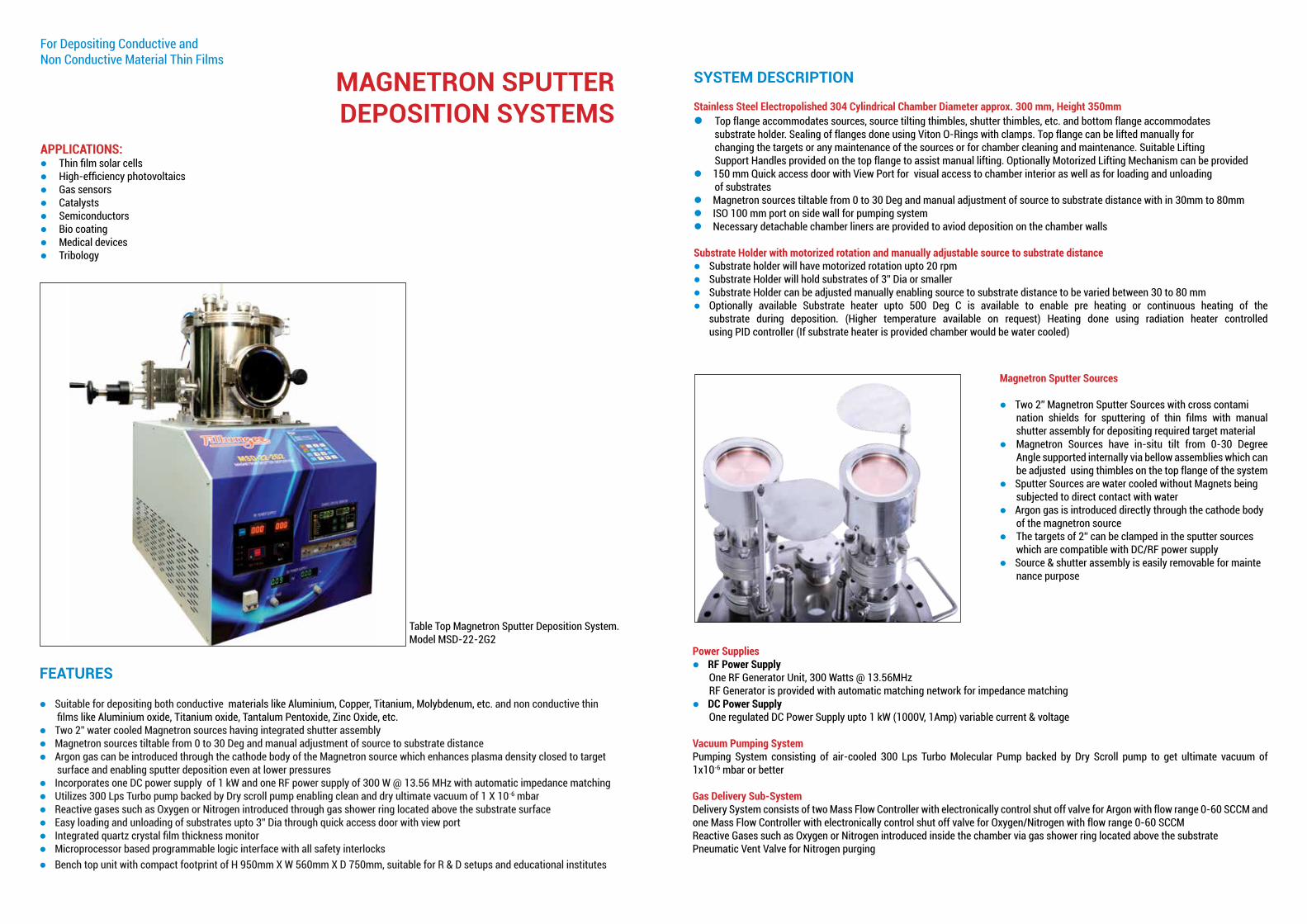
MAGNETRON SPUTTER DEPOSITION SYSTEMS
FEATURES
lSuitable for depositing both conductive materials like Aluminium, Copper, Titanium, Molybdenum, etc. and non conductive thin films like Aluminium oxide, Titanium oxide, Tantalum Pentoxide, Zinc Oxide, etc.lTwo 2” water cooled Magnetron sources having integrated shutter assemblylMagnetron sources tiltable from 0 to 30 Deg and manual adjustment of source to substrate distance lArgon gas can be introduced through the cathode body of the Magnetron source which enhances plasma density closed to target surface and enabling sputter deposition even at lower pressureslIncorporates one DC power supply of 1 kW and one RF power supply of 300 W @ 13.56 MHz with automatic impedance matchinglUtilizes 300 Lps Turbo pump backed by Dry scroll pump enabling clean and dry ultimate vacuum of 1 X 10⁻⁶ mbarlReactive gases such as Oxygen or Nitrogen introduced through gas shower ring located above the substrate surfacelEasy loading and unloading of substrates upto 3” Dia through quick access door with view portlIntegrated quartz crystal film thickness monitor lMicroprocessor based programmable logic interface with all safety interlockslBench top unit with compact footprint of H 950mm X W 560mm X D 750mm, suitable for R & D setups and educational institutes
SYSTEM DESCRIPTION
Stainless Steel Electropolished 304 Cylindrical Chamber Diameter approx. 300 mm, Height 350mmlTop flange accommodates sources, source tilting thimbles, shutter thimbles, etc. and bottom flange accommodates substrate holder. Sealing of flanges done using Viton O-Rings with clamps. Top flange can be lifted manually for changing the targets or any maintenance of the sources or for chamber cleaning and maintenance. Suitable Lifting Support Handles provided on the top flange to assist manual lifting. Optionally Motorized Lifting Mechanism can be providedl150 mm Quick access door with View Port for visual access to chamber interior as well as for loading and unloading of substrateslMagnetron sources tiltable from 0 to 30 Deg and manual adjustment of source to substrate distance with in 30mm to 80mmlISO 100 mm port on side wall for pumping systemlNecessary detachable chamber liners are provided to aviod deposition on the chamber walls
Substrate Holder with motorized rotation and manually adjustable source to substrate distancelSubstrate holder will have motorized rotation upto 20 rpmlSubstrate Holder will hold substrates of 3” Dia or smallerlSubstrate Holder can be adjusted manually enabling source to substrate distance to be varied between 30 to 80 mmlOptionally available Substrate heater upto 500 Deg C is available to enable pre heating or continuous heating of the substrate during deposition. (Higher temperature available on request) Heating done using radiation heater controlled using PID controller (If substrate heater is provided chamber would be water cooled)
For Depositing Conductive and Non Conductive Material Thin Films
APPLICATIONS:l Thin film solar cells l High-efficiency photovoltaics l Gas sensors l Catalysts l Semiconductors l Bio coating l Medical devicesl Tribology
Magnetron Sputter Sources
lTwo 2” Magnetron Sputter Sources with cross contami nation shields for sputtering of thin films with manual shutter assembly for depositing required target materiallMagnetron Sources have in-situ tilt from 0-30 Degree Angle supported internally via bellow assemblies which can be adjusted using thimbles on the top flange of the systemlSputter Sources are water cooled without Magnets being subjected to direct contact with waterlArgon gas is introduced directly through the cathode body of the magnetron sourcelThe targets of 2” can be clamped in the sputter sources which are compatible with DC/RF power supplylSource & shutter assembly is easily removable for mainte nance purpose
Power SupplieslRF Power Supply One RF Generator Unit, 300 Watts @ 13.56MHz RF Generator is provided with automatic matching network for impedance matchinglDC Power Supply One regulated DC Power Supply upto 1 kW (1000V, 1Amp) variable current & voltage
Vacuum Pumping SystemPumping System consisting of air-cooled 300 Lps Turbo Molecular Pump backed by Dry Scroll pump to get ultimate vacuum of 1x10⁻⁶ mbar or better
Gas Delivery Sub-SystemDelivery System consists of two Mass Flow Controller with electronically control shut off valve for Argon with flow range 0-60 SCCM and one Mass Flow Controller with electronically control shut off valve for Oxygen/Nitrogen with flow range 0-60 SCCMReactive Gases such as Oxygen or Nitrogen introduced inside the chamber via gas shower ring located above the substratePneumatic Vent Valve for Nitrogen purging
Table Top Magnetron Sputter Deposition System. Model MSD-22-2G2

InstrumentationlCombination Pirani and Penning Gauge measuring atmosphere up to 10-8 mbar is providedlISO 100 Manual Gate Valve is provided to control pressure during deposition. Manual gate vales has fully open and fully closed position sensors interlocked with system pumping and system vent cycles respectively (Optionally Closed Loop Throttle Gate Valve can be provided)lElectro Magnetic Right Angle Valves are provided to control roughing and backing cycles and to isolate the turbo pump when chamber is brought to atmospheric pressure
Quartz Crystal Monitor with sensor and set of 10 crystalsWater-cooled sensor having 6MHz sensing crystal is located inside the chamber with Thickness Monitor on the front panel to digitally display the rate of deposition and thickness. Accuracy of sensor is 0.5% typical, high rate resolution of 0.1 Å per second & 1 Å thickness resolution. Set of 10 crystals are offered
Control Panel l Control is conveniently located in one single bench top cabinet with necessary Safety Interlocks for ‘User Friendly’ operation. Vacuum and Process Control is done via microprocessor based programmable logic interface and provides output to actuate system pumps, MFC & gaugeslAll displays of operating parameters will be on front panel of the Control Console Entire Magnetron Sputter Deposition Unit including the chamber and the control cabinet is Table Top with compact footprint of 760 mm (L) X 560mm (W) X 1050mm (H)
Spares and Accessories lTargetslSet of Viton O-rings
Note: Other configurations such as change in size of magnetron from 2” dia to 3” dia or change in chamber from cylindrical geometry to Box type D-shaped is well possible. Table top systems can accommodates upto 3 numbers of 2” magnetron sources or 2 numbers of 3” magnetron sources but number of power supplies in table top configuration is limited upto two. Other configurations with 3 or more power supplies is well possible in standalone Magnetron Sputter Deposition Systems
Standalone Magnetron Sputter Deposition System Model MSD-22-2G3
3D Model of UHV Multi-chamber Deposition System with Load Lock

NPD-22-1G2
NANOPARTICLE DEPOSITION SYSTEM
APPLICATIONl Thin film solar cells l High-efficiency photovoltaics
For Nanoparticle deposition on substrate with varying film morphologies
The Nanoparticle deposition system NPD-22-1G2 is used to deposit Nanoparticles by “inert gas condensation” method. On account of their unique catalytic, electronic, magnetic and optical properties being different from bulk species, Nanoparticles continue to attract the attention of researchers. The optical, electronic, thermal and magnetic properties of Nanoparticles endow then with potential applied in electronics, optical devices, solid dielectric material, Nano-biological material & high temperature conditions Nanofluids.
PROCESSThe size selected Nanoparticle deposition takes place through sputtering, aggregation and deposition process
CLUSTER SPUTTERING The DC magnetron type discharge is used to generate clusters from the target clamped in the magnetron source. The magnetron based source has an advantage in terms of wide cluster size range varying from fraction of nanometer to around 100 nanometer. DC plasma is ignited in mixture of Argon & Helium and confined closed sputter target by magnetic field of the magnetron. A super saturated vapor of sputtered atom is originated from sputter source in an inert gas atmosphere of Argon & Helium. The Nano-particle deposition source containing the housing is kept at low temperature using Liquid Nitrogen (alternatively chilled water @ < 7 DegC). The deposition chamber is pumped prior to deposition to vacuum level of 5 x 10⁻⁷ mbar or better. The Nanoparticle cluster size can be varied by adjusting:lThe Length over which the clusters aggregate (by manually adjusting the length of magnetron source inside the aggregation zone) via a linear motion drivelThe Magnetron Power; DC power supply is 1 KW (800 V, 1.4 Amp)lFlow of the aggregation gases (Argon & Helium can be each adjusted from 0 - 60 sccm using dedicated mass flow controllers)
CLUSTER AGGREGATIONSputtered clusters are swept through the aggregation zone, typically kept in vacuum level of 0.1-0.5 mbar by Argon & Helium gases where clusters nucleate and grow. The sputtered atoms are cooled in the cooled aggregation zone and further by the Helium gas leading to nucleation and growth of cluster depend on the length of the aggregation zone (resulting in changing resident time), the composition of the Helium & Argon gas mixture and corresponding flow rates as well as the magnetron power. The nucleation & growth of clusters cease after expansion through the nozzle into the deposition chamber where clusters expand at much lower pressure to of about 0.5 mtorr to 5 mtorr.
CLUSTER DEPOSITIONThe focused cluster beam is then accelerated on to the substrate using bias; DC power supply is 1KW (800V, 1.4 Amp). The system is capable of depositing Nanoparticle with low rates of 0.01 Å/sec to higher rates of about 1 Å/sec. The substrate can be rotated up to 20 rpm and can be heated up to 500⁰ Deg C using radiation heater and controlled using PID controller and thermocouple.
CHAMBERStainless steel electropolished spherical chamber of 12” diameter. Necessary table for mounting with leveling jacks and castor wheels for mobility
SYSTEM DESCRIPTION
NANOPARTICLE DEPOSITION SOURCENanoparticle source includes 2” DC Magnetron Sputter source enclosed in Liquid Nitrogen cooled (alternatively water cooled @ < 7 Deg C) internal chamber, in which sputtered vapors are condensed under high pressure environment where nanoparticles are formed as the thermalized atoms migrate towards the expansion zone of the source. The DC Magnetron source inside the Nanoparticle Deposition Source assembly has a facility of linearly manipulation via Bellow sealed manually operated Linear Motion Drive within a distance of ± 50mm
VACUUM SYSTEMAn air-cooled 700 Lps Turbo Molecular Pump connected to Spherical deposition chamber, backed by 15 m3/hr dry scroll pump to get an ultimate vacuum of 5 x 10⁻⁷ mbar or betterAn air-cooled 300 Lps Auxiliary Turbo Molecular Pump connected to Nanoparticle Source, backed by 10 m3/hr dry scroll pump
SUBSTRATE HANDLINGSubstrate holder capable to hold substrate of 4” dia and capable to rotate up to 20 rpmThe substrate can be heated up to 500 Deg C using Radiation heater assembly, controlled using PID Controller and thermocoupleSubstrate holder has facility of being provided with a bias voltage
POWER SUPPLIESTwo DC Power supplies (one for magnetron source and second for substrate biasing) with 1KW power (800V, 1.4A) for depositing conductive films such as copper, molybdenum, gold, etc. DC power supply will be voltage, current or power controlled and will have automatic arc suppression circuitry and output accuracy of ±1% of nominal voltage, current or power. DC power supply has built in EMI filter circuit.
QUARTZ CRYSTAL MONITOR WITH SENSOR HEAD & SET OF 10 CRYSTALSWater-cooled sensor head, located inside the chamber with Thickness Monitor on the front panel to digitally display the rate of deposition and thickness. Accuracy of sensor head is 0.5% typical.
INSTRUMENTATION lCombination Pirani and Penning gauge capable of measuring pressure inside the deposition chamber from atmosphere to 1x10⁻⁸ mbar rangelSeparate Pirani Gauge capable of measuring pressure inside the Nanoparticle Deposition Source from atmosphere to 1x10⁻³ mbar rangelTwo Mass flow controllers calibrated for Argon & Helium (0 - 60 sccm) lElectro-magnetic Vent valve for venting / nitrogen purging
CONTROL PANEL Combination Control is conveniently located with necessary Safety Interlocks for ‘User Friendly’ operationProcess Control is done using 16 keys keypad controller with LCD display via user friendly microprocessor based programmable logic interface to enable below operations of the system:lPumping & gauge readouts lVacuum pumping system controllSubstrate rotation lSubstrate heatinglDeposition thickness measurement lChamber venting/ gas purging
l Gas sensorsl Catalysts
l Semiconductors l Bio coating
l Medical devices
Aluminum Nanoparticles deposited on SiliconCopper Nanoparticles deposited on Silicon
Image Courtesy: University of Pune

TCS-0204
THERMAL COATING SYSTEM
High vacuum Thermal coating system TCS-0204 incorporates resistive heating source in form of tungsten, molybdenum or tantalum boats, filaments, baskets etc., to evaporate the material to be deposited and raise its vapor pressure to a useful range. This is done in high vacuum, both to allow the vapor to reach the substrate without reacting with or scattering against other gas-phase atoms in the chamber, and reduce the incorporation of impurities from the residual gas in the vacuum chamber. Thermal evaporation is the simplest way of depositing low melting point materials onto substrates.
FEATURESlSystem chamber available in Stainless Steel Box Type D-shaped and Stainless Steel Cylindrical geometries lSingle source/Multi source/Co-evaporationlCompatible to all types of evaporation source (boat, filaments, basket etc.)lSubstrate size upto maximum 6” diameterlSubstrate heating and rotation with height adjustment. lThickness measurement & controllStandalone unit suitable for R&D setups and educational instituteslHigh/Ultra high Vacuum environment based evaporation possible
TECHNICAL DATA
CHAMBER Water cooled Box type D-shaped (Cylindrical geometry available optionally) Stainless steel vacuum chamber of about 350mm L x 350mm W x 450mm H. Chamber will have hinged type front opening door sealed using Viton ‘O’ ring for loading & unloading of substrates as well as evaporation material. Chamber will have viewport of ISO 63 with manual shutter for visual access to chamber interior. Necessary detachable liners are provided to avoid deposition on chamber walls
THERMAL SOURCE The source consists of 4 evaporation source holders, in the form of either Tungsten or Molybdenum boats. Evaporation sources are powered using Electrolytic Pure Copper Electrodes. Necessary water cooled electrical feedthroughs are provided. Option for heating single or maximum upto any two sources is possible with adequate power supplies and electrical contactor mechanism. Manually operated mechanical shutters will be provided over the Evaporation sources. Evaporation sources are isolated by cross contamination shields
POWER SUPPLY Two power supplies with 10 Volts, 200 Amps (Optionally 12 Volts, 500 Amps) are provided. Necessary water cooled electrical feed throughs to the electrodes made of electrolytic pure copper to enable single or co-evaporation is provided
SUBSTRATE HOLDER Substrate Holder is capable of holding substrate up to maximum 6” Ø or squares or small sizes and capable of heating up to 800 degree C with an accuracy of ±5 °C with PID controller. Substrate has motorized rotation upto 60 rpm. Manually operated Substrate shutter is provided. Source to Substrate distance can be varied manually between 150 to 200 mm. In-situ source to substrate distance adjustment is also optionally available
PUMPING SYSTEM Pumping System consisting of Turbo pump of 300 Lps backed by 12 m3 /hr Rotary Pump with oil-mist Filter (Optionally dry scroll pump available) to get ultimate vacuum of 1 x 10⁻⁶ mbar
VACUUM GAUGES Pirani & penning gauge combination capable to measure chamber pressure from atmosphere up to 10-8 mbar is provided
THICKNESS MEASUREMENT Quartz Crystal Film Thickness Monitor with water cooled sensor and set of 10 crystals for monitoring Film Thickness. Water-cooled sensor having 6MHz sensing crystal will be located inside the chamber with Thickness Monitor on the front panel to digitally display the rate of deposition and thickness. Accuracy of sensor is 0.5% typical, high rate resolution of 0.1 Å per second & 1 Å thickness resolution
CHAMBER ISOLATION Electro-pneumatic ISO 100 Gate Valve for the isolation is provided. Electro-magnetic vent valve is provided for purging dry Nitrogen or air
TABLE & CONTROLLER Necessary control for vacuum read-outs, current and voltage readouts and emergency shutdown switch are provided on the front panel of the System. The entire System is mounted on Castor Wheels for mobility
SPARES & ACCESSORIES Tungsten/ Molybdenum/ Tantalum Boats/ Baskets/ FilamentsSet of spare Viton O-ringsSet of chamber liners
For Evaporating Low Melting Point Materials For Creating Multilayer & Co-evaporated Thin Film
APPLICATIONl Thin film solar cells l High-efficiency photovoltaics l Gas sensors l Catalysts l Semiconductors l Bio coating l Medical devicesl Tribology

TVH-1500
THERMOVAC HEATERFor substrate heating & annealing applications under vacuum or inert gas environment
TVH-1500 is an ideal solution for R&D Laboratories and institutes, for vacuum based heating and annealing applications for upto 3” substratesHeating/ annealing can be done either in vacuum or under inert gas environment, typically under ArgonThe heater is capable to heat substrate from ambient to 1500°C and inert gas purge can be done via needle valveTypical applications include Semiconductors, Metallurgy and Surface Sciences
FEATURESl Heating source made of high quality pyrolytic graphite
coated with pyrolytic boron nitride capable of reaching temperatures up to 1500°C
l Heater made of high quality Molybdenum capable of withstanding high temperatures
l Temperature control done via integrated PID controllerl Vacuum chamber consists of high quality quartz glass bell
jar, sealed to the base plate via L-shaped Viton O-ring. Optionally water cooled stainless steel bell jar with quartz glass view port is also available
l High current electrical feedthroughs are cooled via cooling water channels provided in the Base plate
l System is pumped to 10-2 mbar vacuum range via rotary vacuum pump
l Gas purge can be done via fine control needle valvel Safety interlocked controls simplify operation ideal for
multi-user environmentTECHNICAL DATACHAMBER Quartz glass bell jar of 200mm dia X 200mm height with sealed using necessary L type Viton gasket. Bell jar will have protective cover for user safety (Optionally a 200 mm Dia X 200 mm height Stainless Steel water cooled bell jar with quartz glass view port is also available)
VACUUM SYSTEM Pump 12 m3 /hr Rotary Vacuum Pump Base Pressure 1x10⁻² mbar Operating Pressure User Variable (0.02 torr upto 1 torr typical)Pressure Regulation Via Needle valve System Vacuum vent Independent Solenoid operated Vent Valve
VACUUM MEASUREMENT Pirani gauge for measuring chamber pressure from atmosphere to 10-3 mbar range
HEATER Molybdenum heater of dia. 120mm capable of heating substrate up to 3” dia from ambient to 1500 deg C with 1% temperature uniformity; heating source consists of pyrolytic graphite coated with pyrolytic boron nitride. Typical time to reach 1500 deg C is about 15 min. Maximum heating cycle time @ > 1000 deg C < = 1500 deg C: 30 min; Maximum heating cycle time @ > 500 deg C < 1000 deg C: 60 min; Maximum heating cycle time @ < 500 deg C: 120 min
POWER INPUT 230V 50Hz 10Amp, Single Phase.
SUBSTRATE HANDLING Upto maximum 3” substrate
GAS SYSTEM Gas inlet via fine controlled needle valve
CONTROL PANEL ON/OFF, Pirani Gauge with temperature controller, display & emergency switch
SPARES & ACCESSORIES Thermocouple, L shaped Viton gasket
MACHINE FOOTPRINT H 410mm x W 410mm x D 410mm
HLD - 1122L
PORTABLE HELIUM LEAK DETECTOR (TURBO VERSION)
HOW IT WORKSThe HLD-1122L Leak Detector design is based on a proven technique that takes advantage of the differences in compression pressures produced by the turbo pump for gases of different molecular weight. For example, the maximum pressure ratio of helium may be 10 or 100, while for oxygen and other are normally far in excess of 1 million. The principle is implemented in the HLD-1122L Leak Detector by introducing helium (another inlet gases such as those resulting from a leak in the test piece) into “turbo pump foreline” rather than into the “normal pump inlet” as in conventional leak detectors. Helium, having a much lower maximum pressure ratio than other gases contained in air, diffuses backwards though the turbo pump to reach the spectrometer tube where it is detected as a leak in the normal manner. Mechanical pump is also attached to the turbo pump foreline and removes all inlet gases, including helium, there is no appreciable loss of sensitivity in the HLD-1122L Leak Detector.
AUTOMATIC TAPPING ACTION By optimizing the maximum pressure ratio between helium and the other gases of heavier molecular weights the turbo pump becomes a trap that filters out the other gases and contamination, such as water vapor, introduced by the connection of the test piece to the leak detector. This eliminates the need for any cryogenic trapping. A turbo pump used in this fashion also acts as a buffer that protects the spectrometer tube that protects the spectrometer tube from pressure bursts that would normally endanger the mass spectrometer tube and trigger protective devices. Interruption of testing due to pressure bursts is less frequent and the unit can be used at pressures about 1000 times than in conventional leak detector, allowing the measurement of gross leaks without the need for special throttling devices or special test techniques.
For Non destructive leak testing using Helium Mass Spectrometry

SPECIFICATIONSSENSITIVITY1 x 10-9 atm cc/sec for helium 8 x 10-11 atm cc/sec for air. Sensitivity equivalent to 2% of full scale deflection on most sensitive (x10) range. Note : HLD - 1122L sensitivity is influenced by the speed of the mechanical pump. Above specifications are obtained with a normal 12m3/hr pump
LEAK DETECTION RANGE 2 x 10⁻⁹ std. CC/s (Min) to 1 x 10⁻⁴ std cc/s (Max)
TIME CONSTANTLess than 2 seconds for helium. The time constant is the time to reach 63% of full leak rate indication
SPECTROMETER TUBE The spectrometer tube is constructed in quality aluminum alloy. Demountable pole pieces are used for quick access to the internal parts of the tube. Dual filament ion source, cold cathode gauge and solid state preamplifier are built in with the tube
LEAK INDICATOR Indicated as exponent value in Std cc/sec (choice of unit available)& corresponding horizontal bar graph on LCD
TEST PORT PRESSURE Indicated as exponent value from atmosphere 1 x 10⁻³ mbar & corresponding bar graph on LCD
SPECTROMETER TUBE PRESSURE Indicated as exponent value from 9.9 x 10⁻⁵ mbar to 1.0 x 10⁻⁶ mbar
AUDIBLE ALARM Includes adjustable audio threshold and volume controls
VALVE BLOCK Electromagnetic Valves for START, TEST and VENT cycles
VACUUM GAUGES Cold cathode gauge indicates the vacuum in the spectrometer tube and thermocouple gauge monitors the TEST PORT PRESSURE
TEST PORT NW 25 KF quick coupling for easy connection to HLD
OPERATING AND CONTROL OF HLD 1122L Complete operational control using 89C51 Philips microcontroller that receives command from navigation keys and send information to LCD
COMMUNICATION RS232 interface is available that can communicate to PC. Dedicated software developed in Visual Basic that allows data logging and operational control is available as an option
CONTROL & INDICATORS LCD acts as interaction between operator & HLD. Operator uses information displayed on LCD & active functions available on LCD can be scrolled & entered by operator. At start, there are only two keys required for operation, scroll & ENTER. All active functions & operating modes are shown on LCD. With RS232 port & optionally available software, it is possible to operate HLD from PC. Software is written using Visual Basic 6.0 & data logging and complete supervision along with full report generation & printing is possible. Diagnostic LED display indicates status of valves & switches on HLD. This is useful to get information on the current operational status. HLD tuning board enables tuning & calibration of HLD through specific procedures
OPERATION The object to be tested is connected to the test port and evacuated when TEST OBJECT function is entered by operator. Helium entering through a leak diffuses instantly into the foreline of the turbo pump. A constant pressure ratio is maintained between the foreline and the spectrometer tube, which measures the amount of helium in the system and converts it into an electrical signal. The signal is measured and interpreted as leak rate value and bar. When the helium source is removed from the leak, the helium remaining in the system is rapidly pumped away. Thus the effect is a rise and fall to the leak rate indication.
HLD-1122L CABINET
HELIUM LEAK TESTING SERVICES H. Fillunger provides helium leak testing services to our clients as per requirement either on-site or in-house. Leak Testing is done using Fillunger make Helium Mass Spectrometer Leak Detector Model HLD1122L which is capable to detect leaks up to 2.0 X 10⁻⁹ std cc / sec
Leak testing services are provided by our technically qualified and Level II Engineers certified by American Standard for Non Destructive Testing (ASNT)
Methods of Leak Testing
1. Evacuation Method:This method of leak testing is used for components which are subjected to vacuum conditions in their normal operation. In this method the test job is evacuated to a rough vacuum and helium is sprayed on the welding / sealing surfaces of the job, traces of which can be detected in case of leaks.This method of leak testing is typically used for all types of valves, bellows, vacuum chambers, welded pipes, etc.
2. Sniffer Probe Method:This method of leak testing is used for components which are subjected to high pressure in their normal operation. In this method Helium gas is pressurized inside the test component and traces of helium are detected using a sniffer probe.This method of leak testing is typically used for all types of aluminum castings, pressure vessels, heat exchangers, intank tap changers, vacuum interrupters/ circuit breakers/ switchgears, nuclear fuel tube bundles, pressure gauges, etc.
3. Bombing Method:Components which can neither be evacuated nor pressurized but are required to be leak tested for hermetic sealing are tested by this method. In this method hermetically sealed components are placed in a chamber which is pressurized with Helium gas. The components are kept in the chamber for a predefined time after which they are removed from the chamber and tested using the Sniffer probe to detect the traces of helium in case of individual components. In case components need to be tested in batches, after being pressurized with Helium Gas, they need to be placed in another vacuum chamber which can be evacuated and traces of Helium in the Chamber can be detected in case of any leaks.This method of leak testing is typically used for Hermetically sealed electronic components like Saw filters, Resonators, Crystal oscillators, Glass to Metal Seals, Ceramic to Metal seals, Vacuum tubes, Thermocouples, Diodes, Transistor Cans, etc.
Customized and Automated Special Purpose Leak Testing Setups for production lines can be designed as per requirement upon request.
Some of the major sectors we provide services to are
l Nuclear Power
l Thermal Power
l Petroleum and Petrochemical Industry
l Aeronautical and Space Research
l Heavy Electrical Equipment Industry
l Heat Exchanger / Pressure Vessels / Vapor Absorption Chiller Manufacturers
l Hermetically sealed component manufacturers
l Manufacturers and Users of Vacuum Chambers for Re-search applications like ultra high vacuum beam lines, particle accelerators, surface science studies, plasma and ion research, etc.
l Valve Manufacturers

COMPONENTS ISO-KF FLANGES & FITTINGSFillunger offers wide range of quick couplings flanges & fittings ideally suited for high vacuum applications requiring rapid & frequent assembly & dismantling. ISO-KF flanges comply with ISO specifications. The method of fastening & sealing is achieved by a radial clamp that provides uniform compression of an elastomer gasket fitted between two symmetrical flanges. The elastomer gasket is mounted on a center ring the extensions of which fit into grooves of mating flanges. Quick Coupling components are available in sizes ranging from ½” to 2” diameters.
Featuresl KF compatible design l Symmetric, non-rotatable geometries l Viton® / Neoprene O-rings l Glass bead blasted finish l All high vacuum fittings are TIG welded & are leak tested l Custom-built KF flanges & fittings are available on demand
Specifications
MaterialslFlanges / Tubing : AISI-304 (304L/316/316L available on request)lO-rings : Viton ® / Neoprene elastomer
VacuumlRange : 1x10⁻⁷ TorrlLeak Rate : < 2x10⁻⁹ std cc/sec of Helium
Temperature RangelViton up to 150⁰0 C lNeoprene up to 100⁰0 C
ISO FLANGES & FITTINGSFillunger offers large diameter ISO flanges& fittings which are available in bore sizes between 2 ½ “ to 25 “. ISO flange system is ideally suited for applications requiring rapid & frequent assembly & dismantling. These flanges can operate in high vacuum environments to pressures better than 1x10⁻⁷ Torr. The method of fastening & sealing in K-type flanges is achieved by using multiple double-claw clamp assemblies that provide uniform compression of an elastomer gasket trapped between two mating flanges. The elastomer gasket is mounted on a center ring the extension of which fit into grooves of mating flanges. The method of fastening & sealing in F-type flanges is achieved by using bolts. These flanges are typically used where low profile geometry is required. ISO-F type rotatable flanges are also available.
Featuresl Fast connect & disconnect l Economical reusable fittings l Viton ® / Neoprene O-rings l Varied fastening methods l Symmetric, non-rotatable geometries l Glass bead blasted finish
Specifications MaterialslFlanges, center rings : AISI-304(304L/316/316L available on request)lClamps : Aluminium quick clampslSeal : Viton ® / Neoprene elastomer
VacuumlRange : 1x10⁻⁷ TorrlLeak Rate : < 2x10⁻⁹ std cc/sec of Helium
Temperature RangelViton up to 150⁰⁰0 C lNeoprene up to 100⁰0 C⁰
COMPONENTS CF FLANGES & FITTINGSFillunger CF flanges & fittings are manufactured as per international vacuum standards. The UHV seal is made by trapping a copper gasket between two flanges. The flanges have a sharp knife-edge on their operating face. When joined together with a set of bolts, these knife-edges bite on flat surface of copper gasket to make UHV tight seal.
NON-ROTATABLE & ROTATABLE FLANGESNon-rotatable flanges are often referred as fixed flanges & are constructed of a single machined piece. Once non-rotatable flanges are welded in place, their bolt holes are fixed in position. The orientation is straddling the vertical centerline. Rotatable flanges are made from two pieces with knife-edge part & external bolt holes ring being separate. Once the knife-edge is welded in position, it is very easy to change the orientation of bolt holes relative to the axis of port. Thus, rotatable flanges are ideal for situations where alignment of a component to a chamber needs to be set accurately before the flange mounting bolts are tightened.
FeatureslConflat ® compatible lRotatable & Non-rotatable geometries lThrough holes or tapped lDouble sided flangeslReducing flanges lClearance bolt holes
Specifications
MaterialslFlanges : AISI-304 (304L/316/316L available on request)lBolts : AISI-304lGasket : OFHC copper / Teflon
Vacuum lOFHC copper seal : <1x10⁻⁸ Torr with bake-out up to 2500 C lLeak Rate : < 2x10⁻⁹ std cc/sec of Helium
Temperature RangelOFHC Copper seal 250⁰ 0 C
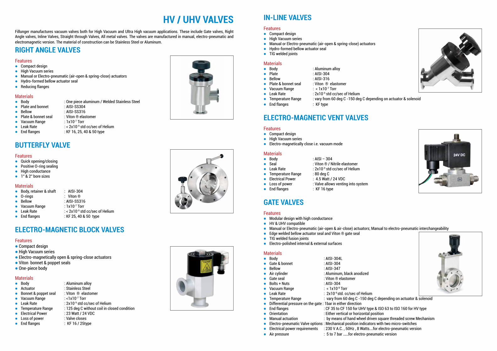
HV / UHV VALVES Fillunger manufactures vacuum valves both for High Vacuum and Ultra High vacuum applications. These include Gate valves, Right Angle valves, Inline Valves, Straight through Valves, All metal valves. The valves are manufactured in manual, electro-pneumatic and electromagnetic version. The material of construction can be Stainless Steel or Aluminum.
RIGHT ANGLE VALVESFeatureslCompact designlHigh Vacuum series lManual or Electro-pneumatic (air-open & spring-close) actuatorslHydro-formed bellow actuator seallReducing flanges
MaterialslBody : One piece aluminum / Welded Stainless SteellPlate and bonnet : AISI-SS304lBellow : AISI-SS316lPlate & bonnet seal : Viton ® elastomer lVacuum Range : 1x10⁻⁷ Torr lLeak Rate : < 2x10⁻⁹ std cc/sec of HeliumlEnd flanges : KF 16, 25, 40 & 50 type
BUTTERFLY VALVEFeatureslQuick opening/closinglPositive O-ring sealing lHigh conductancel1” & 2” bore sizes
MaterialslBody, retainer & shaft : AISI-304lO-rings : Viton ®lBellow : AISI-SS316lVacuum Range : 1x10⁻⁷ Torr lLeak Rate : < 2x10⁻⁹ std cc/sec of HeliumlEnd flanges : KF 25, 40 & 50 type
ELECTRO-MAGNETIC BLOCK VALVESFeaturesl Compact designl High Vacuum series l Electro-magnetically open & spring-close actuatorsl Viton bonnet & poppet sealsl One-piece body
MaterialslBody : Aluminum alloylActuator : Stainless SteellBonnet & poppet seal : Viton ® elastomerlVacuum Range : <1x10⁻⁷ Torr lLeak Rate : 2x10⁻⁹ std cc/sec of HeliumlTemperature Range : 125 deg C without coil in closed conditionlElectrical Power : 23 Watt / 24 VDC lLoss of power : Valve closeslEnd flanges : KF 16 / 25type
IN-LINE VALVESFeatureslCompact designlHigh Vacuum series lManual or Electro-pneumatic (air-open & spring-close) actuatorslHydro-formed bellow actuator seallTIG welded joints
MaterialslBody : Aluminum alloylPlate : AISI-304lBellow : AISI-316lPlate & bonnet seal : Viton ® elastomerlVacuum Range : < 1x10⁻⁷ TorrlLeak Rate : 2x10⁻⁹ std cc/sec of HeliumlTemperature Range : vary from 60⁰ deg C -150 deg ⁰C depending on actuator & solenoidlEnd flanges : KF type
ELECTRO-MAGNETIC VENT VALVESFeatureslCompact designlHigh Vacuum series lElectro-magnetically close i.e. vacuum mode
MaterialslBody : AISI – 304 lSeal : Viton ® / Nitrile elastomerlLeak Rate : 2x10⁻⁹ std cc/sec of HeliumlTemperature Range : 80⁰ deg ClElectrical Power : 4.5 Watt / 24 VDC lLoss of power : Valve allows venting into systemlEnd flanges : KF 16 type
GATE VALVESFeatureslModular design with high conductancelHV & UHV compatible lManual or Electro-pneumatic (air-open & air-close) actuators; Manual to electro-pneumatic interchangeabilitylEdge welded bellow actuator seal and Viton ® gate seallTIG welded fusion joints lElectro-polished internal & external surfaces
MaterialslBody : AISI-304LlGate & bonnet : AISI-304lBellow : AISI-347lAir cylinder : Aluminum, black anodizedlGate seal : Viton ® elastomerlBolts + Nuts : AISI-304lVacuum Range : < 1x10⁻⁸ TorrlLeak Rate : 2x10⁻⁹ std. cc/sec of HeliumlTemperature Range : vary from 60 deg ⁰C -150 deg ⁰C depending on actuator & solenoidlDifferential pressure on the gate : 1bar in either directionlEnd flanges : CF 35 to CF 150 for UHV type & ISO 63 to ISO 160 for HV typelOrientation : Either vertical or horizontal positionlManual actuation : by means of hand wheel driven square threaded screw MechanismlElectro-pneumatic Valve options : Mechanical position indicators with two micro-switches lElectrical power requirements : 230 V A.C. , 50Hz , 8 Watts….for electro-pneumatic versionlAir pressure : 5 to 7 bar ……for electro-pneumatic version
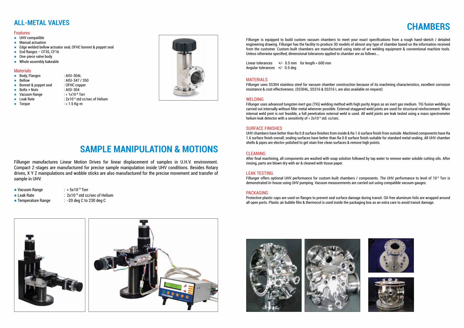
ALL-METAL VALVESFeatureslUHV compatiblelManual actuation lEdge welded bellow actuator seal, OFHC bonnet & poppet seallEnd flanges – CF35, CF16lOne-piece valve bodylWhole assembly bakeable
MaterialslBody, Flanges : AISI-304LlBellow : AISI-347 / 350lBonnet & poppet seal : OFHC copperlBolts + Nuts : AISI-304lVacuum Range : < 1x10⁻⁸ TorrlLeak Rate : 2x10⁻⁹ std cc/sec of HeliumlTorque : > 1.5 Kg-m
SAMPLE MANIPULATION & MOTIONSFillunger manufactures Linear Motion Drives for linear displacement of samples in U.H.V. environment. Compact Z-stages are manufactured for precise sample manipulation inside UHV conditions. Besides Rotary drives, X Y Z manipulations and wobble sticks are also manufactured for the precise movement and transfer of sample in UHV.
l Vacuum Range : < 5x10⁻⁹ Torrl Leak Rate : 2x10⁻⁹ std cc/sec of Heliuml Temperature Range : -20 deg ⁰C to 230⁰ deg C
CHAMBERS Fillunger is equipped to build custom vacuum chambers to meet your exact specifications from a rough hand-sketch / detailed engineering drawing. Fillunger has the facility to produce 3D models of almost any type of chamber based on the information received from the customer. Custom-built chambers are manufactured using state-of-art welding equipment & conventional machine tools. Unless otherwise specified, dimensional tolerances applied to chamber are as follows….
Linear tolerances +/- 0.5 mm for length < 600 mmAngular tolerances +/- 0.5⁰ deg
MATERIALSFillunger uses SS304 stainless steel for vacuum chamber construction because of its machining characteristics, excellent corrosion resistance & cost effectiveness. (SS304L, SS316 & SS316 L are also available on request)
WELDINGFillunger uses advanced tungsten inert gas (TIG) welding method with high purity Argon as an inert gas medium. TIG fusion welding is carried out internally without filler metal wherever possible. External staggered weld joints are used for structural reinforcement. When internal weld joint is not feasible, a full penetration external weld is used. All weld joints are leak tested using a mass spectrometer helium leak detector with a sensitivity of < 2x10⁻⁹ std. cc/sec.
SURFACE FINISHESUHV chambers have better than Ra 0.8 surface finishes from inside & Ra 1.6 surface finish from outside. Machined components have Ra 1.6 surface finish overall; sealing surfaces have better than Ra 0.8 surface finish suitable for standard metal sealing. All UHV chamber shells & pipes are electro-polished to get stain free clean surfaces & remove high points.
CLEANINGAfter final machining, all components are washed with soap solution followed by tap water to remove water soluble cutting oils. After rinsing, parts are blown dry with air & cleaned with tissue paper.
LEAK TESTINGFillunger offers optional UHV performance for custom-built chambers / components. The UHV performance to level of 10-9 Torr is demonstrated in-house using UHV pumping. Vacuum measurements are carried out using compatible vacuum gauges.
PACKAGINGProtective plastic caps are used on flanges to prevent seal surface damage during transit. Oil-free aluminum foils are wrapped around all open ports. Plastic air bubble film & thermocol is used inside the packaging box as an extra care to avoid transit damage.

Our Valued Customers
Testimonials
March 18, 2014
To Whom It May Concern
This is to certify that we purchased a UHV chamber for molecular beam instrument on 2002 from H. Fillunger and Co. Pvt. Ltd., Pune. It was working fine and we were able to maintain a vacuum of 10-10 Torr with just a turbomolecular pump (220 l/s) backed by a rotary pump. Very recently we dismantled the above unit and a redesigned UHV chamber is in place to integrate the molecular beam with PM-IRAS. Even without any bake out, a vacuum of 10-9 Torr could be maintained. We used the old and using new UHV chambers to measure surface catalysis reactions on metal single crystals. Both the chambers were made according to given specifications by H. Fillunger and Co. Pvt. Ltd., Pune.
Dr. C. S. Gopinath Senior Principal Scientist at Catalysis Division, Head, Center of Excellence on Surface Science NCL, Pune 411 008, India Ph: 020-2590 2043 Fax: 020-2590 2633 [email protected] nclwebapps.ncl.res.in/csgopinath/

*Specifications subject to change without notice.
Sales & Service Locations:
Pune (Head Office and Factory) New DelhiMumbaiChennaiBengaluruKolkata
H Fillunger & Co. Pvt. Ltd.Mumbai-Pune Road, Opp. Empire Estate,Near Premier Ltd., Pimpri, Pune 411 018 INDIA
Tel.: +91-20-27468616/17 +91-9763718050 / 51Fax: +91-20-27468614
[email protected]@fillunger.com
www.fillunger.com