file_9374241033_im_en_582415
DESCRIPTION
VRVTRANSCRIPT
En-1
En
gli
sh
Refrigerant
R410A
INSTALLATION INSTRUCTION SHEET(PART NO. 9374241033)
Multi Air Conditioning Systemfor Buildings (VRF System)
OUTDOOR MODELAJ A72LBTF
MASTER AJ A90LBTFAJ 126LBTF
AJ A72UBTFSLAVE AJ A90UBTF
AJ 126UBTF
Contents
1. SAFETY PRECAUTIONS .........................................................................2
2. PRECAUTIONS FOR USING THE ALTERNATIVE REFRIGERANT....... 3
3. ACCESSORIES ........................................................................................4
4. INSTALLATION WORK ............................................................................54.1. SELECTING AN INSTALLATION LOCATION .............................................. 5
4.2. TRANSPORTING THE PRODUCT .............................................................. 6
4.3. INSTALLATION DIMENSIONS..................................................................... 7
4.4 INSTALLATION THE UNIT ........................................................................... 9
4.5. SYSTEM LAYOUT...................................................................................... 10
4.6. PIPE SELECTION...................................................................................... 11
4.7. PIPE INSTALLATION ................................................................................. 12
4.8. INSTALLING INSULATION ........................................................................ 17
4.9. DRAIN PROCESSING ............................................................................... 17
4.10. ELECTRICAL WIRING ............................................................................... 18
4.11. FIELD SETTING ........................................................................................ 23
5. CHARGING WITH REFRIGERANT ........................................................ 285.1. SEALING TEST ......................................................................................... 28
5.2. VACUUM PROCESS ................................................................................. 29
5.3. ADDITIONAL CHARGING ......................................................................... 29
6. TEST RUN...............................................................................................316.1. PRE-TEST RUN CHECK ITEMS ............................................................... 31
6.2. TEST RUN METHOD ................................................................................. 31
6.3. CHECKLIST ............................................................................................... 31
7. ERROR DISPLAY ...................................................................................327.1. NORMAL OPERATION MODE .................................................................. 32
7.2. ERROR OPERATION MODE ..................................................................... 33
8. PUMP DOWN ..........................................................................................34
9. OPTION PARTS ......................................................................................35
10. INFORMATION .......................................................................................36
9374241033_IM_en_p01-17.p65 26/8/2008, 18:231
En-2
1. SAFETY PRECAUTIONS
• Be sure to read this Sheet thoroughly before installation.• The warnings and precautions indicated in this Sheet contain important information pertaining to your safety. Be sure to observe
them.• After installing the unit, perform a test run to make sure the unit operates normally. Then, explain to the customer how to operate and
maintain the unit.• Hand this Sheet, together with the Operating Manual to the customer.
Request the customer to keep them on hand for future use, such as for relocating or repairing the unit.
• Request your dealer or a professional installer to install the unit in accordance with this Sheet.An improperly installed unit can cause serious accidents such as water leakage, electric shock, or fire.If the unit is installed in disregard of the instructions in the Installation Instruction Sheet, it will void themanufacturer’s warranty.
• For installation purposes, be sure to use the parts supplied by the manufacturer or other prescribed parts.The use of non-prescribed parts can cause serious accidents such as the unit to fall, water leakage, electricshock, or fire.
• To install a unit that uses the R410A refrigerant, use dedicated tools and piping materials that have beenmanufactured specifically for R410A use.Because the pressure of the R410A refrigerant is approximately 1.6 times higher than the R22, failure to usededicated piping material or improper installation can cause rupture or injury.Furthermore, it can cause serious accidents such as water leakage, electric shock, or fire.
• Do not introduce any substance other than the prescribed refrigerant into the refrigeration cycle.If air enters the refrigeration cycle, the pressure in the refrigeration cycle will become abnormally high andcause the piping to rupture.
• Be sure to install the unit as prescribed, so that it can withstand earthquakes and typhoons or other strongwinds.Improper installation can cause the unit to topple or fall, or other accidents.
• If there is a refrigerant leakage, make sure that it does not exceed the concentration limit.If a refrigerant leakage exceeds the concentration limit, it can lead to accidents such as oxygen starvation.
• If a refrigerant leakage occurs during operation, immediately vacate the premises and thoroughly ventilatethe area.If the refrigerant is exposed to fire, it will create a hazardous gas.
• Electrical work must be performed in accordance with this Sheet by a person certified under the national orregional regulations. Be sure to use a dedicated circuit for the unit.An insufficient power supply circuit or improperly performed electrical work can cause serious accidentssuch as electric shock or fire.
• For wiring, use the prescribed type of wires, connect them securely, making sure that there are no externalforces of the wires applied to the terminal connections.Improperly connected or secured wires can cause serious accidents such as overheating the terminals,electric shock, or fire.
• Securely install the electrical box cover on the unit.An improperly installed electrical box cover can cause serious accidents such as electric shock or fire throughexposure to dust or water.
• Do not turn ON the power until all work has been completed.Turning ON the power before the work is completed can cause serious accidents such as electric shock orfire.
• After the installation, make sure there is no refrigerant leakage.If the refrigerant leaks into the room and becomes exposed to a source of fire such as a fan heater, stove, orburner, it will create a hazardous gas.
WARNING!This mark indicates procedures which, if improperly performed, might lead to the death or seriousinjury of the user.
9374241033_IM_en_p01-17.p65 26/8/2008, 18:232
En-3
• Do not install the unit in the following areas:• Area with high salt content, such as at the seaside.
It will deteriorate metal parts, causing the parts to fall or the unit to leak water.• Area filled with mineral oil or containing a large amount of splashed oil or steam, such as a kitchen.
It will deteriorate plastic parts, causing the parts to fall or the unit to leak water.• Area that generates substances that adversely affect the equipment, such as sulfuric gas, chlorine gas,
acid, or alkali.It will cause the copper pipes and brazed joints to corrode, which can cause refrigerant leakage.
• Area containing equipment that generates electromagnetic interference.It will cause the control system to malfunction, preventing the unit from operating normally.
• Area that can cause combustible gas to leak, contains suspended carbon fibers or flammable dust, orvolatile inflammables such as paint thinner or gasoline.If gas leaks and settles around the unit, it can cause a fire.
• Do not use the unit for special purposes, such as storing food, raising animals, growing plants, or preserv-ing precision devices or art objects.It can degrade the quality of the preserved or stored objects.
• Ground the unit.Do not connect the ground wire to a gas pipe, water pipe, lightning rod, or a telephone ground wire.Improper grounding may cause electric shock.
• Install a ground leakage breaker.If a ground leakage breaker is not installed, it may cause electric shock or fire.
• Perform drain work in accordance with this Sheet, and ensure that the drain water is properly drained.If the drain processing is improperly installed, water may drip down from the unit, wetting the furniture.
• Do not touch the fins with bare hands.
CAUTION!This mark indicates procedures which, if improperly performed, might possibly result in personalharm to the user, or damage to property.
2. PRECAUTIONS FOR USING THE ALTERNATIVE REFRIGERANT
Pay careful attention to the following points :
• Since the working pressure is 1.6 times higher than that of R22 models, some of the piping and installation and service tools arespecial. (See the table in the SPECIAL TOOLS FOR R410A section.)Especially, when replacing a conventional refrigerant (other than R410A) model with a new refrigerant R410A model, alwaysreplace the conventional piping and flare nuts with the R410A piping and flare nuts.
• Models that use refrigerant R410A have a different charging port thread diameter to prevent erroneous charging with R22, R407Cand for safety. Therefore, check beforehand. [The charging port thread diameter for R410A is 1/2 UNF 20 threads per inch.]
• Be more careful than the installation of the refrigerant (other than R410A) models, not to enter foreign matters (oil, water, etc.) andother refrigerant into the piping. Also, when storing the piping, securely seal the openings by pinching, taping, etc.
• When charging the refrigerant, take into account the slight change in the composition of the gas and liquid phases, and alwayscharge from the liquid phase side whose composition is stable.
Contents of change
Pressure is huge and cannot be measured with a conventional gauge. To prevent erroneous mixing of otherrefrigerants, the diameter of each port has been changed.It is recommended to use a gauge manifold with a high pressure display range –0.1 to 5.3 MPa and a lowpressure display range –0.1 to 3.8 MPa.
To increase pressure resistance, the hose material and base size were changed.
A conventional vacuum pump can be used by installing a vacuum pump adapter.
Special gas leakage detector for HFC refrigerant R410A.
Tool name
Gauge manifold
Charging hose
Vacuum pump
Gas leakage detector
SPECIAL TOOL FOR R410A
PRECAUTIONS FOR USING THE R410A REFRIGERANT
9374241033_IM_en_p01-17.p65 26/8/2008, 18:233
En-4
3. ACCESSORIES
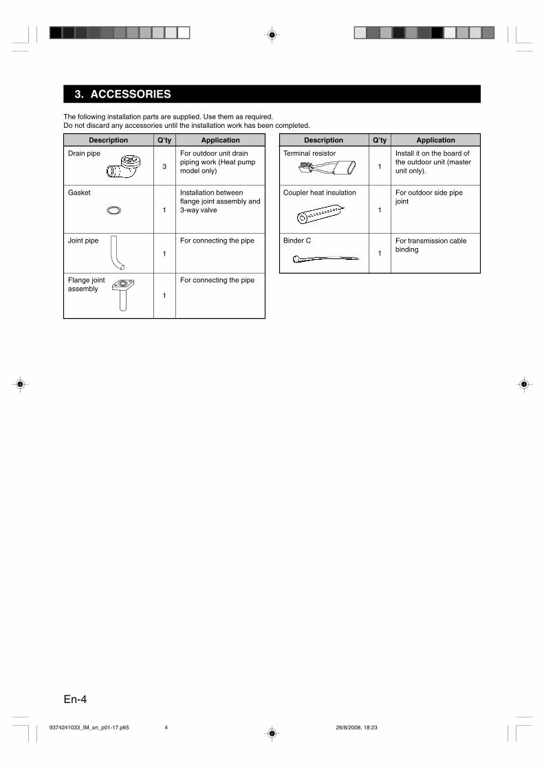
The following installation parts are supplied. Use them as required.Do not discard any accessories until the installation work has been completed.
Description
Drain pipe
Gasket
Joint pipe
Flange jointassembly
Q’ty
3
1
1
1
Application
For outdoor unit drainpiping work (Heat pumpmodel only)
Installation betweenflange joint assembly and3-way valve
For connecting the pipe
For connecting the pipe
Description
Terminal resistor
Coupler heat insulation
Binder C
Q’ty
1
1
1
Application
Install it on the board ofthe outdoor unit (masterunit only).
For outdoor side pipejoint
For transmission cablebinding
9374241033_IM_en_p01-17.p65 26/8/2008, 18:234
En-5
4. INSTALLATION WORK
Make sure to obtain the customer’s approval for selecting and installing the unit.
4.1. SELECTING AN INSTALLATION LOCATION
WARNING
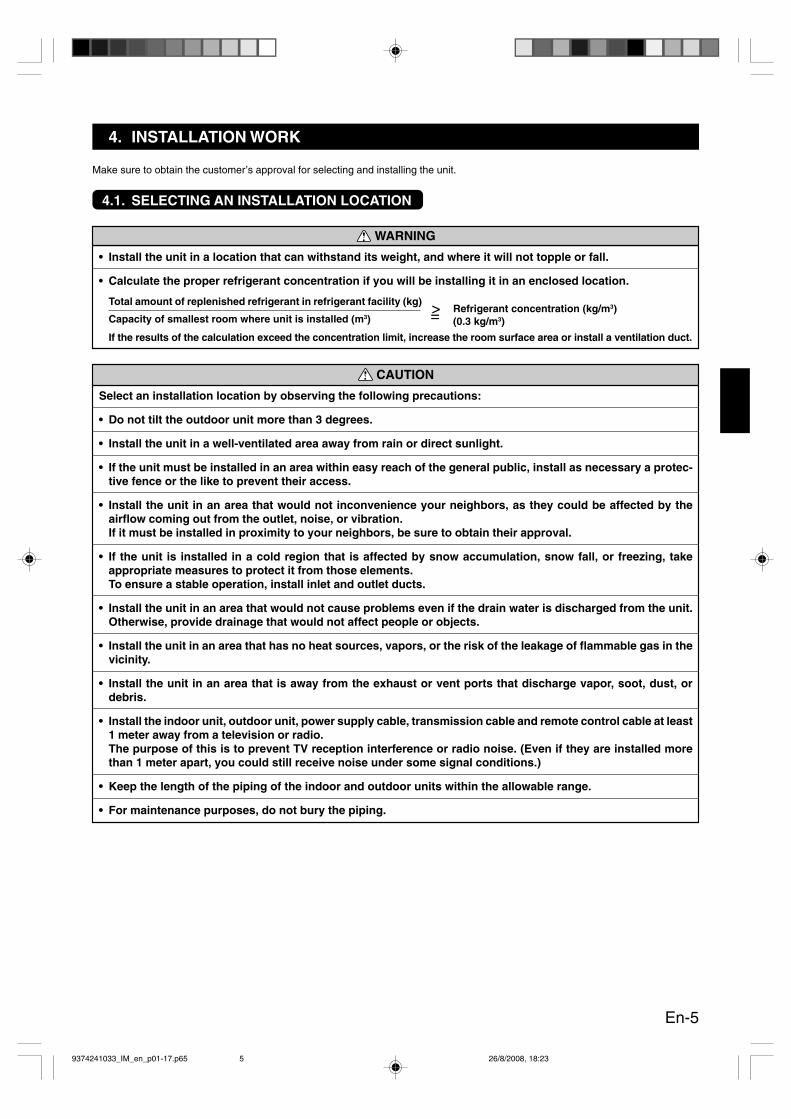
• Install the unit in a location that can withstand its weight, and where it will not topple or fall.
• Calculate the proper refrigerant concentration if you will be installing it in an enclosed location.
Total amount of replenished refrigerant in refrigerant facility (kg)
Capacity of smallest room where unit is installed (m3)Refrigerant concentration (kg/m3)(0.3 kg/m3)
If the results of the calculation exceed the concentration limit, increase the room surface area or install a ventilation duct.
CAUTION
Select an installation location by observing the following precautions:
• Do not tilt the outdoor unit more than 3 degrees.
• Install the unit in a well-ventilated area away from rain or direct sunlight.
• If the unit must be installed in an area within easy reach of the general public, install as necessary a protec-tive fence or the like to prevent their access.
• Install the unit in an area that would not inconvenience your neighbors, as they could be affected by theairflow coming out from the outlet, noise, or vibration.If it must be installed in proximity to your neighbors, be sure to obtain their approval.
• If the unit is installed in a cold region that is affected by snow accumulation, snow fall, or freezing, takeappropriate measures to protect it from those elements.To ensure a stable operation, install inlet and outlet ducts.
• Install the unit in an area that would not cause problems even if the drain water is discharged from the unit.Otherwise, provide drainage that would not affect people or objects.
• Install the unit in an area that has no heat sources, vapors, or the risk of the leakage of flammable gas in thevicinity.
• Install the unit in an area that is away from the exhaust or vent ports that discharge vapor, soot, dust, ordebris.
• Install the indoor unit, outdoor unit, power supply cable, transmission cable and remote control cable at least1 meter away from a television or radio.The purpose of this is to prevent TV reception interference or radio noise. (Even if they are installed morethan 1 meter apart, you could still receive noise under some signal conditions.)
• Keep the length of the piping of the indoor and outdoor units within the allowable range.
• For maintenance purposes, do not bury the piping.
>=
9374241033_IM_en_p01-17.p65 26/8/2008, 18:235

En-6
4.2. TRANSPORTING THE PRODUCT Fig. 4.2-1
Fig. 4.2-2
<Front>
Protective boards
Rope suspension area
Fork (Manual forklift)Delivery pallet Fork (Forklift)
Transporting with ropes (Fig. 4.2-1)• To transport the outdoor unit to the installation location by sus-
pending it, use the four cutouts that are located in the front andback to pass a rope under the base.
• As you transport the unit, make sure the unit is vertical.The unit could fall if you tilt the unit during transport.
• For transport, use a rope that can fully withstand the weight ofthe unit.
• Do not apply shocks to the unit during transport.• Use a protective plate to prevent the bell mouth from coming in
contact with the rope. Failure to use a protective plate can causethe bell mouth to become deformed or damaged.
• Use 2 rope which are 8 m in length or longer.
Transporting on a forklift (Fig. 4.2-2)• To transport the unit on a forklift, slide the forks of the forklift
through the opening between the unit and the delivery pallet.This will enable the unit and the delivery pallet to be removed.
• Protect the unit from scratches during installation.
Transporting on a manual forklift (Fig. 4.2-2)• To transport the unit on a manual forklift, slide the forks of the
manual forklift through the opening of the side of the deliverypallet. This will enable the removal of the unit and the deliverypallet.
• Protect the unit from scratches during installation.<Side>
Product mass
About 380 kg
9374241033_IM_en_p01-17.p65 26/8/2008, 18:236
En-7
4.3. INSTALLATION DIMENSIONS
CAUTION
Be careful of the following issues for selecting position of outdoor unit.
• Install with sufficient space when taking into consideration such as conveyance routes, installation space,walk space and maintenance.
• Observe the installation space specifications that are shown in the figures.If installation is not performed according to the specifications, it could cause a short circuit and result in alack of performance.As a result, outdoor unit might be stopped by high-pressure protection easily.
• During installation, take into account the installation space required for the refrigerant piping space.
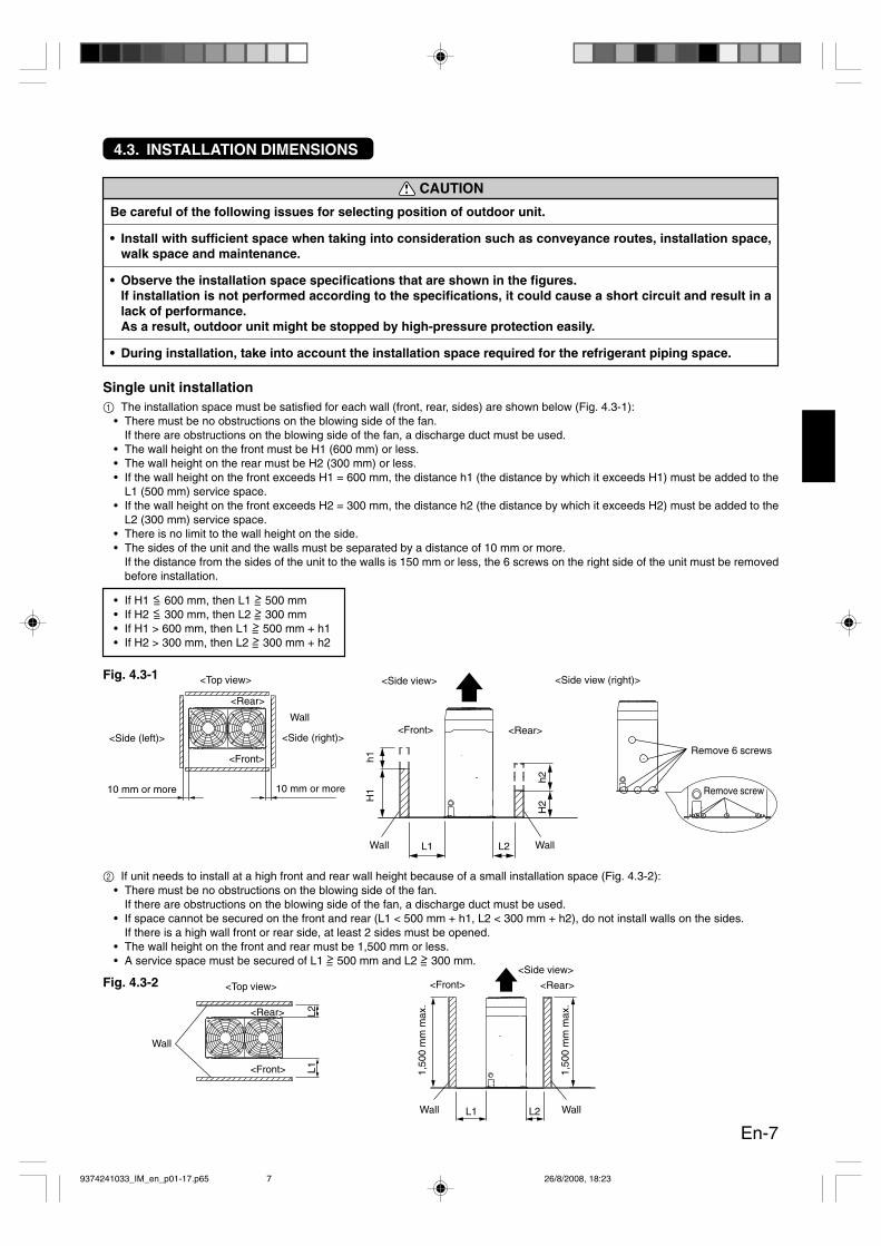
Single unit installation1 The installation space must be satisfied for each wall (front, rear, sides) are shown below (Fig. 4.3-1):
• There must be no obstructions on the blowing side of the fan.If there are obstructions on the blowing side of the fan, a discharge duct must be used.
• The wall height on the front must be H1 (600 mm) or less.• The wall height on the rear must be H2 (300 mm) or less.• If the wall height on the front exceeds H1 = 600 mm, the distance h1 (the distance by which it exceeds H1) must be added to the
L1 (500 mm) service space.• If the wall height on the front exceeds H2 = 300 mm, the distance h2 (the distance by which it exceeds H2) must be added to the
L2 (300 mm) service space.• There is no limit to the wall height on the side.• The sides of the unit and the walls must be separated by a distance of 10 mm or more.
If the distance from the sides of the unit to the walls is 150 mm or less, the 6 screws on the right side of the unit must be removedbefore installation.
• If H1 <= 600 mm, then L1 >= 500 mm• If H2 <= 300 mm, then L2 >= 300 mm• If H1 > 600 mm, then L1 >= 500 mm + h1• If H2 > 300 mm, then L2 >= 300 mm + h2
Fig. 4.3-1
2 If unit needs to install at a high front and rear wall height because of a small installation space (Fig. 4.3-2):• There must be no obstructions on the blowing side of the fan.
If there are obstructions on the blowing side of the fan, a discharge duct must be used.• If space cannot be secured on the front and rear (L1 < 500 mm + h1, L2 < 300 mm + h2), do not install walls on the sides.
If there is a high wall front or rear side, at least 2 sides must be opened.• The wall height on the front and rear must be 1,500 mm or less.• A service space must be secured of L1 >= 500 mm and L2 >= 300 mm.
Fig. 4.3-2
10 mm or more
<Top view>
10 mm or more
<Side view>
Wall
<Side (left)> <Side (right)>
<Front>
<Rear>
<Side view (right)>
Remove 6 screws
Remove screw
<Rear><Front>
Wall Wall
h1H
1
h2H
2
L1 L2
<Top view>
L2L1
Wall
<Front>
<Side view>
<Rear><Front>
L1 L2Wall
1,50
0 m
m m
ax.
1,50
0 m
m m
ax.
Wall
<Rear>
9374241033_IM_en_p01-17.p65 26/8/2008, 18:237

En-8
Multiple Connections
1 Installation space must be satisfied for each wall (front, rear, sides) are shown below (Fig. 4.3-3):• There must be no obstructions on the blowing side of the fan.
If there are obstructions on the blowing side of the fan, a discharge duct must be used.• The wall height on the front must be H1 (600 mm) or less.• The wall height on the rear must be H2 (300 mm) or less.• If the wall height on the front exceeds H1 = 600 mm, the distance h1 (the distance by which it exceeds H1) must be added to the
L1 (500 mm) service space.• If the wall height on the front exceeds H2 = 300 mm, the distance h2 (the distance by which it exceeds H2) must be added to the
L2 (300 mm) service space.• There is no limit to the wall height on the side.• The side of the unit and the walls must be separated by a distance of 10 mm or more.
If the distance from the sides of the unit to the walls is 150 mm or less, the 6 screws on the right side of the unit must be removedbefore installation.
• If H1 <= 600 mm, then L1 >= 500 mm• If H2 <= 300 mm, then L2 >= 300 mm• If H1 > 600 mm, then L1 >= 500 mm + h1• If H2 > 300 mm, then L2 >= 300 mm + h2
Fig. 4.3-3
2 If unit needs to install at a high front and rear wall height because of a small installation space (Fig. 4.3-4):• There must be no obstructions on the blowing side of the fan.
If there are obstructions on the blowing side of the fan, a discharge duct must be used.• If space cannot be secured on the front and rear (L1 < 500 mm + h1, L2 < 300 mm + h2), do not install walls on the sides.
If there is a high wall front or rear side, at least 2 sides must be opened.• The wall height on the front and rear must be 1,500 mm or less.• A service space must be secured of L1 >= 500 mm and L2 >= 300 mm.
Fig. 4.3-4
10 mm or more300 mm or more
500 mm or more 10 mm or more 10 mm or more<Front>
Wall
<Rear>
10 mm or more<Side view>
<Rear><Front>
Wall Wall
h1H
1
h2H
2
L1 L2
300 mm or more
500 mm or more 10 mm or more 10 mm or more<Front>
Wall
<Rear>
<Side view>
<Rear><Front>
L1 L2Wall
1,50
0 m
m m
ax.
1,50
0 m
m m
ax.
Wall
9374241033_IM_en_p01-17.p65 26/8/2008, 18:238

En-9
4.4 INSTALLATION THE UNIT
• Install 4 or more anchor bolts at the 8 locations indicated by arrows. (Fig. 4.4-1)• Keep the left and right anchor bolts 850 mm or more apart from each other.
This does not apply when anchor bolts are installed in all 8 locations.• To reduce vibration, do not install the unit directly on the ground.
Instead, install it on a secure base (such as concrete blocks). (Fig. 4.4-2) Depending on the installation conditions, the unit mayspread its vibration during operation, which may cause noise and vibration.Therefore, attach damping materials (such as damping pads) to the unit during installation.
• If you will be installing a foundation, be sure to take the routing of the pipe connections into account.• Before securing the unit, make sure the anchor bolts are tightened securely.
Fig. 4.4-1
3 The number of outdoor units that may be connected is 1 system (3 units connected) (Fig. 4.3-5).• To install more than 1 outdoor unit system, provide a distance between each refrigerant system.• Do not install walls at the sides.
Fig. 4.3-5
500
mm
or m
ore
300
mm
or m
ore
1,300 mm
646
mm
678
mm
703
mm
1,000 mm850 mm Bolt (M10) × 4NO GOOD OK OK
* Do not use a four-corner support foundation.
ø12 (hole) × 8 places
Front
1,000 mmor more
<Front>
Wall
500 mmor more
800 mmor more
300 mmor more
300 mmor more
1,000 mmor more
300 mmor more
WallWall
10 m
m o
r m
ore
10 m
m o
r m
ore
10 m
m o
r m
ore
10 m
mor
mor
e
10 m
m o
r m
ore
10 m
m o
r m
ore
10 m
m o
r m
ore
10 m
mor
mor
e
<Fro
nt>
<R
ear>
<Fro
nt>
<R
ear>
<Fro
nt>
<Fro
nt>
Fig. 4.4-2 Installation example
<Rear>
<R
ear>
<R
ear>
9374241033_IM_en_p01-17.p65 26/8/2008, 18:239

En-10
A) In case of one outdoor unit connected• From outdoor unit to the farthest indoor unit:
e+f+g+i+k+m <= 150 m (actual pipe length),e+o+p+r+t <= 150 m (actual pipe length)
• From the first separation tube to the farthest indoor unit:o+p+r+t <= 60 m (actual pipe length)
• Difference in height between outdoor units and indoor units (H1)50 m: For the indoor unit stated below40 m: For the outdoor unit stated below
• Difference in height between indoor units and indoor unitsH2 <= 15 m, H3 <= 15 m
• e+f+g+h+i+j+k+l+m+n+o+p+q+r+s+t+u <= 300 m (total pipe length)
NOTE : If the outdoor temperature during cooling operationis expected to be –5 °C or less, do not install the out-door unit lower than the indoor unit.
B) In case of two outdoor unit connected• From outdoor unit to the farthest indoor unit:
a+e+f+g+i+k+m <= 150 m (actual pipe length)a+e+o+p+r+t <= 150 m (actual pipe length)
• Difference in height between outdoor units and indoor units (H1)50 m: For the indoor unit stated below40 m: For the outdoor unit stated below
• From the first separation tube to the farthest indoor unit:o+p+r+t <= 60 m (actual pipe length)
• Difference in height between indoor units and indoor units (H2, H3)H2 <= 15 m, H3 <= 15 m
• Difference in height between outdoor unit and outdoor units: (H4)H4 <= 0.5 m
• From outdoor unit to outdoor unit branch kita, d <= 3 m
• a+d+e+f+g+h+i+j+k+l+m+n+o+p+q+r+s+t+u <= 300 m (total pipelength)
• Outdoor capacityMaster >= Slave
C) In case of three outdoor unit connected• From outdoor unit to the farthest indoor unit:
a+e+f+g+i+k+m <= 150 m (actual pipe length)a+e+o+p+r+t <= 150 m (actual pipe length)
• From the first separation tube to the farthest indoor unit:o+p+r+t <= 60 m (actual pipe length)
• Difference in height between outdoor units and indoor units (H1)50 m: For the indoor unit stated below40 m: For the outdoor unit stated below
• Difference in height between indoor units and indoor units (H2, H3)H2 <= 15 m, H3 <= 15 m
• Difference in height between outdoor unit and outdoor units: (H4)H4 <= 0.5 m
• From outdoor unit to outdoor unit branch kita, b, c <= 3 m
• Piping length between the farthest outdoor unit to the first out-door unit branch kita, b, c <= 3 m, c+d, b+d <= 12 m
• a+b+c+d+e+f+g+h+i+j+k+l+m+n+o+p+q+r+s+t+u <= 300 m (to-tal pipe length)
• Outdoor unit capacityMaster >= Slave 1 >= Slave 2
4.5. SYSTEM LAYOUT
CAUTION
If there are multiple outdoor units to be connected, make sure to install the master unit near the indoor unit.If 3 outdoor units are to be connected, install them in descending order, starting with the one with the largestcapacity closest to the indoor unit.
Fig. 4.5-1
Fig. 4.5-2
Fig. 4.5-3
f ge
i k m
o
p
q s
h j l n
Outdoorunit
(Master)
r t H3
H2
H1
u
H3
Indoorunit
Indoorunit
Indoorunit
Indoorunit
Indoorunit
Indoorunit
Indoorunit
Indoorunit
Indoorunit
Outdoorunit 1
(Master)
Outdoorunit 2
(Slave)
Indoorunit
Indoorunit
Indoorunit
Indoorunit
Indoorunit
Indoorunit
Indoorunit
Indoorunit
Indoorunit
H4
a
f ge d
i k m
o
p
q s
h j l n
r t H3
H2
H1
u
H3
Outdoorunit 1
(Master)
Outdoorunit 2
(Slave 1)
Outdoorunit 3
(Slave 2)
Indoorunit
Indoorunit
Indoorunit
Indoorunit
Indoorunit
Indoorunit
Indoorunit
Indoorunit
Indoorunit
cH4
b
f ge d
i k m
o
p
q s
h j l n
r t H3
H2
H1
u
H3
a
9374241033_IM_en_p01-17.p65 26/8/2008, 18:2310
En-11
4.6. PIPE SELECTION
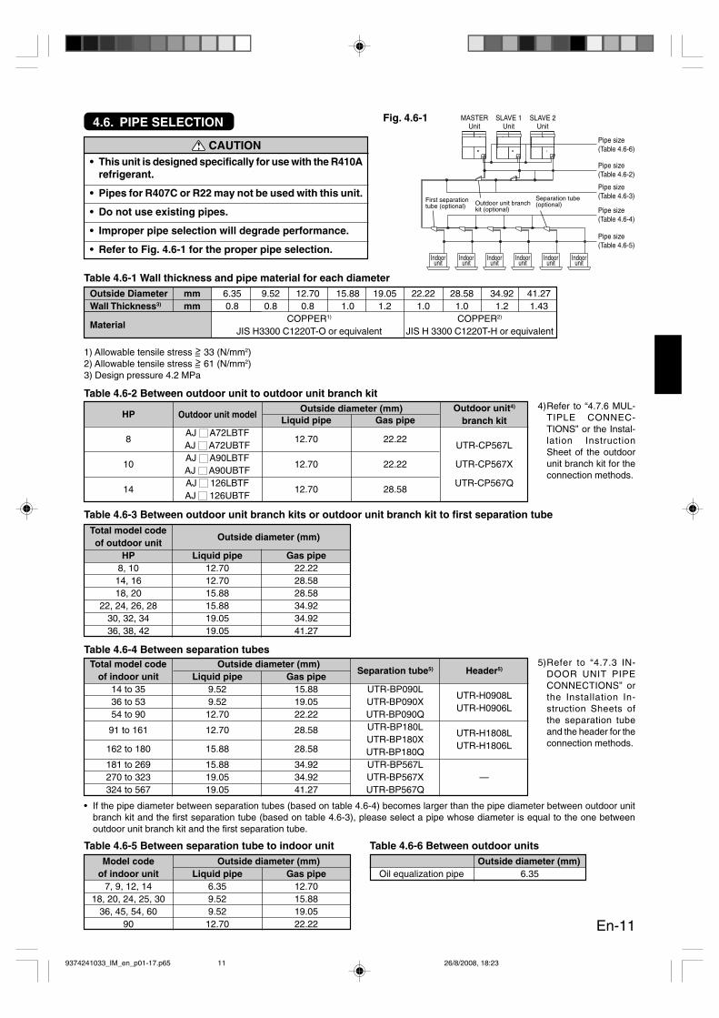
CAUTION• This unit is designed specifically for use with the R410A
refrigerant.
• Pipes for R407C or R22 may not be used with this unit.
• Do not use existing pipes.
• Improper pipe selection will degrade performance.
• Refer to Fig. 4.6-1 for the proper pipe selection.
Outside Diameter mm 6.35 9.52 12.70 15.88 19.05 22.22 28.58 34.92 41.27Wall Thickness3) mm 0.8 0.8 0.8 1.0 1.2 1.0 1.0 1.2 1.43
MaterialCOPPER1) COPPER2)
JIS H3300 C1220T-O or equivalent JIS H 3300 C1220T-H or equivalent
Table 4.6-1 Wall thickness and pipe material for each diameter
1) Allowable tensile stress >= 33 (N/mm2)2) Allowable tensile stress >= 61 (N/mm2)3) Design pressure 4.2 MPa
Liquid pipe Gas pipe
8AJ A72LBTF
12.70 22.22AJ A72UBTF UTR-CP567L
10AJ A90LBTF
12.70 22.22 UTR-CP567XAJ A90UBTF
14AJ 126LBTF
12.70 28.58UTR-CP567Q
AJ 126UBTF
Table 4.6-2 Between outdoor unit to outdoor unit branch kitOutside diameter (mm)
Table 4.6-3 Between outdoor unit branch kits or outdoor unit branch kit to first separation tubeTotal model codeof outdoor unit
Outside diameter (mm)
HP Liquid pipe Gas pipe8, 10 12.70 22.2214, 16 12.70 28.5818, 20 15.88 28.58
22, 24, 26, 28 15.88 34.9230, 32, 34 19.05 34.9236, 38, 42 19.05 41.27
Table 4.6-4 Between separation tubesTotal model code Outside diameter (mm)
of indoor unit Liquid pipe Gas pipeSeparation tube5) Header5)
14 to 35 9.52 15.88 UTR-BP090LUTR-H0908L
36 to 53 9.52 19.05 UTR-BP090XUTR-H0906L
54 to 90 12.70 22.22 UTR-BP090Q
91 to 161 12.70 28.58 UTR-BP180LUTR-H1808L
UTR-BP180XUTR-H1806L162 to 180 15.88 28.58 UTR-BP180Q
181 to 269 15.88 34.92 UTR-BP567L—270 to 323 19.05 34.92 UTR-BP567X
324 to 567 19.05 41.27 UTR-BP567Q
Table 4.6-5 Between separation tube to indoor unitModel code Outside diameter (mm)
of indoor unit Liquid pipe Gas pipe7, 9, 12, 14 6.35 12.70
18, 20, 24, 25, 30 9.52 15.8836, 45, 54, 60 9.52 19.05
90 12.70 22.22
Pipe size(Table 4.6-6)
MASTERUnit
Indoorunit
Indoorunit
Indoorunit
Indoorunit
Indoorunit
Indoorunit
SLAVE 1Unit
SLAVE 2Unit
Pipe size(Table 4.6-2)
Pipe size(Table 4.6-3)
Pipe size(Table 4.6-4)
Pipe size(Table 4.6-5)
HP Outdoor unit model
Fig. 4.6-1
Table 4.6-6 Between outdoor unitsOutside diameter (mm)
Oil equalization pipe 6.35
First separationtube (optional) Outdoor unit branch
kit (optional)
Separation tube(optional)
Outdoor unit4)
branch kit
• If the pipe diameter between separation tubes (based on table 4.6-4) becomes larger than the pipe diameter between outdoor unitbranch kit and the first separation tube (based on table 4.6-3), please select a pipe whose diameter is equal to the one betweenoutdoor unit branch kit and the first separation tube.
4)Refer to “4.7.6 MUL-TIPLE CONNEC-TIONS” or the Instal-lation InstructionSheet of the outdoorunit branch kit for theconnection methods.
5)Refer to “4.7.3 IN-DOOR UNIT PIPECONNECTIONS” orthe Installation In-struction Sheets ofthe separation tubeand the header for theconnection methods.
9374241033_IM_en_p01-17.p65 26/8/2008, 18:2311
En-12
4.7. PIPE INSTALLATION
4.7.1. BRAZING
CAUTION
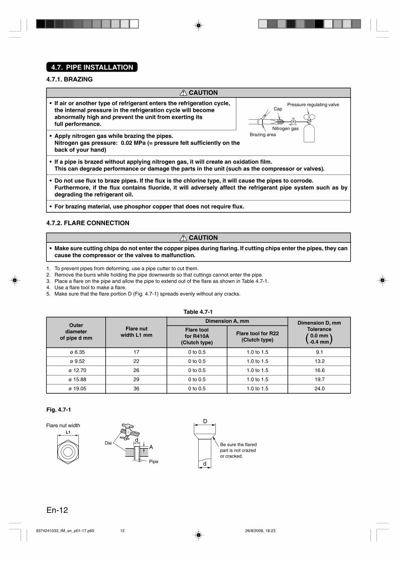
• If air or another type of refrigerant enters the refrigeration cycle,the internal pressure in the refrigeration cycle will becomeabnormally high and prevent the unit from exerting itsfull performance.
• Apply nitrogen gas while brazing the pipes.Nitrogen gas pressure: 0.02 MPa (= pressure felt sufficiently on theback of your hand)
• If a pipe is brazed without applying nitrogen gas, it will create an oxidation film.This can degrade performance or damage the parts in the unit (such as the compressor or valves).
• Do not use flux to braze pipes. If the flux is the chlorine type, it will cause the pipes to corrode.Furthermore, if the flux contains fluoride, it will adversely affect the refrigerant pipe system such as bydegrading the refrigerant oil.
• For brazing material, use phosphor copper that does not require flux.
1. To prevent pipes from deforming, use a pipe cutter to cut them.2. Remove the burrs while holding the pipe downwards so that cuttings cannot enter the pipe.3. Place a flare on the pipe and allow the pipe to extend out of the flare as shown in Table 4.7-1.4. Use a flare tool to make a flare.5. Make sure that the flare portion D (Fig. 4.7-1) spreads evenly without any cracks.
4.7.2. FLARE CONNECTION
CAUTION
• Make sure cutting chips do not enter the copper pipes during flaring. If cutting chips enter the pipes, they cancause the compressor or the valves to malfunction.
Fig. 4.7-1
Flare nut width
Die
Pipe
dA
L1
Outerdiameter
of pipe d mm
Flare nutwidth L1 mm
Dimension A, mm
Flare toolfor R410A
(Clutch type)
Flare tool for R22(Clutch type)
ø 6.35 17 0 to 0.5 1.0 to 1.5 9.1
ø 9.52 22 0 to 0.5 1.0 to 1.5 13.2
ø 12.70 26 0 to 0.5 1.0 to 1.5 16.6
ø 15.88 29 0 to 0.5 1.0 to 1.5 19.7
ø 19.05 36 0 to 0.5 1.0 to 1.5 24.0
Table 4.7-1
Dimension D, mmTolerance
0.0 mm-0.4 mm( )
Pressure regulating valveCap
Brazing areaNitrogen gas
D
d
Be sure the flaredpart is not crazedor cracked.
9374241033_IM_en_p01-17.p65 26/8/2008, 18:2312

En-13
NO GOOD
NO GOOD NO GOOD
Horizontalline
VIEW C
Outdoorunit side
H1 =0 mm –10 mm
(α1 : 0° – 1°)β1: -10° – 10°
Gas pipe
Liquid pipe Horizontalline
VIEW D
Outdoorunit side
H2 =0 mm –10 mm
(α2 : 0° – 1°)β2: -10° – 10°
Verticalline
Horizontalline
4.7.3. INDOOR UNIT PIPE CONNECTIONS
CAUTION
Separation tubeHorizontal Vertical
OKA : Outdoor unit or Refrigerant branch kitB : Indoor unit or Refrigerant branch kit
Header
C
H1α1
β1
D
H2α2
β2
OK
• Do not connect a separation tube after a header.• Leave the distance 0.5 m or more for straight part to branch tube and header.
• For details, refer to the Installation Instruction Sheet of each part.
A
B A B
AB
Main pipe 0.5 m or moreTo indoorunit
0.5 m or moreTo indoorunit
4.7.4. PIPE ROUTING DIRECTION
CAUTION
• Be careful not to deform or scratch the panel while opening the knockout holes.
• After opening the knockout holes, deburr the edges to prevent them from cutting the wires.
Horizontal line
or
±15°
To indoor unit
Pipes can be connected from 4 directions. (Figs. 4.7-2, 3, 4)(Knockout holes are provided so that pipes can be connected from all 4 different directions.)
Fig. 4.7-2 Knockoutposition
Fig. 4.7-3 Detail of knockout position (front/side/rear)
Front
Rear
98
220 22 35 13 8080
5015
6
120
119
141 39 139 39
Knockout holeKnockout hole
Knockout hole
[Rear][Front] [Side]
Fig. 4.7-4 Knockoutposition in bottom
210
30
194
3675
Knockout hole
Right
orHeader
Separation tube
orHeader
Separation tube
To indoorunit
To indoorunit
9374241033_IM_en_p01-17.p65 26/8/2008, 18:2313

En-14
• Weld the flange joint, joint pipe, and the main piping.* Apply nitrogen gas while welding the pipes.
• Tighten the flares of the connection pipes on the valves (3-way valve: oil, gas, and liquid pipes) of the outdoor unit.Refer to Table 4.7-2 for the tightening torque values.* For an single unit installation, do not connect the oil pipe.
• Make sure to use 2 spanners to tighten the flare nut (Fig. 4.7-5).• Refer to Figs. 4.7-6, 7, and 8 before connecting the connection pipes to the outdoor unit.• Use the gasket (accessory) to connect the flange joint.
Do not use the gasket that comes with the product.• Braze the joint pipe (accessory) to the flange joint assembly (accessory).• Cut the joint pipe (accessory) appropriately in order to extend them from the front, side, and back of the unit.
Fig. 4.7-5 Fig. 4.7-6Gas valveOil valve
Liquid valve
Flare nut
Liquid pipe
Washer
Flange jointassembly
Gasket(Accessory)
Fig. 4.7-7 Front piping
Liquid pipe(Field supply)
To indoor unit
Joint pipe(Accessory)
Flange jointassembly
Knockouthole
Connection pipe
Torquewrench
Indoor unit pipe(Body side)
Flare nut
Wrench (Fixed)
Tighten with two wrenches.
4.7.5. PIPE CONNECTIONS
CAUTION
• Seal the pipe routing holes with putty (supplied locally) so that there will be no gap.If small animals such as insects enter the outdoor unit, they can cause a short circuit in the electrical box.
• To prevent pipes from breaking, do not make sharp bends on them.The pipes may be bended with a curvature radius of 70 mm or more.
• A pipe is likely to break if it is bent many times at the same place.
• Do not make a flare connection on an indoor unit pipe until the connection pipes are connected.
• When connecting the pipe, keep it at the right angle so that the flare can be attached correctly to the 3-way valve.If the flare is not properly centered, the flare nut will not tighten smoothly.The thread may become damaged if you attempt to tighten the flare nut with excessive force.
• To weld the flange joint with the gas pipe, do so with the flange joint detached from the 3-way valve. Weldingthe flange joint with the 3-way valve attached will cause the 3-way valve to malfunction.
Fig. 4.7-8 Bottom piping
Gas pipe (3-way valve)
Liquid pipe (3-way valve)
Oil pipe (3-way valve)
Flare nut
—
49.0 to 61.0 N·m(490 to 610 kgf·cm)
16.0 to 18.0 N·m(160 to 180 kgf·cm)
Bolt of Flange joint34.3 to 39.2 N·m
(350 to 400 kgf·cm)
—
—
Table 4.7-2
Flange jointassembly
Knockouthole
Joint pipe(Accessory)
Oil pipe
Bolt
Gas pipe (Field supply)
9374241033_IM_en_p01-17.p65 26/8/2008, 18:2314

En-15
4.7.6. MULTIPLE CONNECTIONS
CAUTION
• When connecting multiple units (3 units maximum), make sure the master unit has the maximum capacity inthe system.Example:
When connecting multiple outdoor units, designate one of them to be the master unit and others to be theslave units. It is not possible to connect master units in multiples. As shown in the diagram, arrange theoutdoor units so that the master unit should be installed closest to the indoor unit. (Figs. 4.7-9, 10, 11, 12) Useoutdoor unit branch kit (optional) to connect multiple units.
Fig. 4.7-9 Front pipingOutdoor Capacity2 Unit : Master >= Slave 13 Unit : Master >= Slave 1 >= Slave 2
OK
NoGood
Master + Slave 1 + Slave 2AJ 126LBTF + AJ 126UBTFAJ A90LBTF + AJ A72UBTFAJ 126LBTF + AJ 126UBTF + AJ A90UBTFAJ A72LBTF + AJ A72UBTFAJ A90LBTF + AJ 126UBTFAJ A72LBTF + AJ A90UBTF + AJ A90UBTF
Outdoor unit branchkit (Optional)
Liquid pipe(Field supply)
Gas pipe (Field supply)
Oil pipe(Field supply)
Flange jointassembly(Accessory)
Joint pipe(Accessory)
To outdoor unit
To outdoor unit
To indoor unit(To main pipe)
To indoor unit
Outdoor unit(Master)
Outdoor unit(Slave 1)
Outdoor unit(Slave 2)
Vertical
or
NO GOOD NO GOOD NO GOOD
CAUTION
• Be sure to follow the installation restrictions for the outdoor unit branch kit and install it according to theconditions at the installation location.
• Install the outdoor unit branch kit horizontally, within ±10°, so that the refrigerant separates evenly.Do not install the outdoor unit branch kit vertically.
Horizontal
NO
GO
OD
OK
NO
GO
OD N
O
GO
OD
OK
NO
GO
OD
±10°
±10°
• Leave the distance 0.5 m or more for straight part to outdoor unit branch kit.
• For details, refer to the Installation Instruction Sheet of the outdoor unit branch kit.
Outdoor unit branch kit
To outdoor unitTo indoor unit(To main pipe) To outdoor unit
0.5 m or more
To indoor unit (To main pipe)To outdoorunit
To outdoor unit
0.5 m or more
To outdoor unit
9374241033_IM_en_p01-17.p65 26/8/2008, 18:2315
En-16
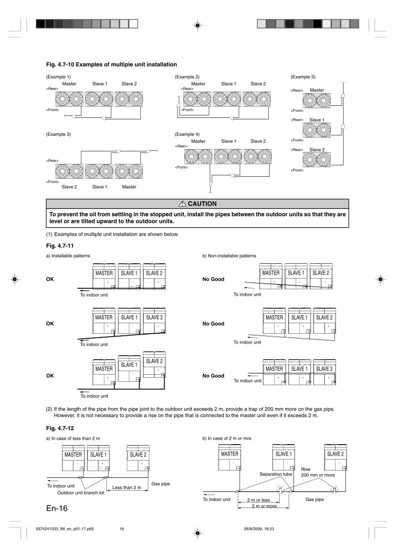
CAUTION
To prevent the oil from settling in the stopped unit, install the pipes between the outdoor units so that they arelevel or are tilted upward to the outdoor units.
(1) Examples of multiple unit installation are shown below.
Fig. 4.7-11
a) Installable patterns b) Non-installable patterns
(2) If the length of the pipe from the pipe joint to the outdoor unit exceeds 2 m, provide a trap of 200 mm more on the gas pipe.However, it is not necessary to provide a rise on the pipe that is connected to the master unit even if it exceeds 2 m.
Fig. 4.7-12
a) In case of less than 2 m b) In case of 2 m or mre
MASTER SLAVE 1 SLAVE 2
MASTER SLAVE 1 SLAVE 2
MASTERSLAVE 1
SLAVE 2
To indoor unit
To indoor unit
To indoor unit
MASTER SLAVE 1 SLAVE 2
MASTER SLAVE 1 SLAVE 2
MASTER SLAVE 1 SLAVE 2
OK
OK
OK
No Good
No Good
No Good
To indoor unit
To indoor unit
To indoor unit
MASTER SLAVE 1 SLAVE 2 MASTER SLAVE 1 SLAVE 2
To indoor unit
To indoor unit
Gas pipe
Outdoor unit branch kitLess than 2 m
Separation tube
Gas pipe2 m or less2 m or more
Rise200 mm or more
Fig. 4.7-10 Examples of multiple unit installation
(Example 1)
Master Slave 1<Rear>
<Front>
Slave 2
(Example 2)
Master Slave 1 Slave 2
(Example 3)
Slave 2 Slave 1
<Rear>
<Front>Master
(Example 4)
Master Slave 1<Rear>
<Front>
Slave 2
(Example 5)
<Rear>
<Front>
Master
Slave 1
Slave 2
<Rear>
<Front>
<Rear>
<Front>
<Rear>
<Front>
9374241033_IM_en_p01-17.p65 26/8/2008, 18:2316

En-17
4.8. INSTALLING INSULATION
• Install a insulation after performing “5.1. SEALING TEST”.• Use an insulation on the refrigerant pipes to prevent condensation
and dripping. (Fig. 4.8-1)• Determine the thickness of the insulation material by referring to Table 4.8-1.
• If the outdoor unit is installed at a level that is higher than the indoor unit, the water that hascondensed in the 3-way valve of the outdoor unit could travel to the indoor unit.Therefore, use putty in the space between the pipe and the insulation to prevent the entry of water.
4.9. DRAIN PROCESSING
Perform the following steps to provide drain processing.• Remove the rear panel.• Open the 3 knockout holes shown in Fig. 4.9-1.• Install the drain pipe (accessories) in the installation hole of the drain cover.• Install a commercially available 16 mm drain hose on the drain pipe.• Always provide drainage at the 3 locations.
Tip immersed in water
<= 70% <= 75% <= 80% <= 85%6.35 8 10 13 179.52 9 11 14 1812.70 10 12 15 1915.88 10 12 16 2019.05 10 13 16 2122.22 11 13 17 2228.58 11 14 18 2334.92 11 14 18 2441.27 12 15 19 25
Table 4.8-1 Selection of insulation(for using an insulation material with equal heat transmission rate or below 0.040 W/(m·k))
Insulation materialMinimum thickness (mm)
Pipe diameter(mm)
Outdoor unit
Gutter10 mm or more
50 mmor more
OK
No Good
hose
Raised Wavy
Fig. 4.9-1
Relative humidity
Drain water could leak from the outdoor unit duringcooling or heating operation.Provide drain processing as necessary.To prevent drain water from flowing around the unit,install a drainage channel as shown on the right.
Knockout hole:Be careful not to deform or scratch the panel while opening the knockout holes.After opening the knockout holes, deburr the edges to prevent them from cutting the wires.
CAUTION
Drain processing:Do not use a drain hose in a cold region, as it can cause the inside of the drain hose to freeze.If it is necessary to provide drainage, take appropriate measures to prevent the inside of the drain hosefrom freezing.
Do not open this knockout hole.
Insulation
Fig. 4.8-1
Putty
Drain pipe mounting holes Rear panelRear panel
Hose
Drain pan
Drain pipe
Open thisknockout hole
Drain hose processing
* When an ambient temperature and relative humidity exceed 32 °C, please strengthen heat insulation of refrigerant pipe.
9374241033_IM_en_p01-17.p65 26/8/2008, 18:2317
En-18
WARNING• Wiring connections must be performed by a qualified person in accordance with specifications.
The voltage rating for this product is 400 V at 50 Hz. It should be operated within the range of 342 to 456 V.
• Before connecting the wires, make sure the power supply is OFF.
• Use a dedicated power supply circuit.
• Install a breaker at the power supply for each outdoor unit.Improper breaker selection can cause electric shock or fire.
• Install a leakage circuit breaker in accordance with the related laws and regulations.
• Connect the connector cord securely to the terminal.Faulty installation can cause a fire.
• Make sure to secure the insulation portion of the connector cable with the cord clamp. A damaged insulationcan cause a short circuit.
• Never install a power factor improvement condenser. Instead of improving the power factor, the condensermay overheat.
• Before servicing the unit, turn the power supply switch OFF. Then, do not touch electric parts for 10 minutesdue to the risk of electric shock.
• Make sure to perform grounding work.Improper grounding work can cause electric shocks.
CAUTION• The primary power supply capacity is for the air conditioner itself, and does not include the concurrent use
of other devices.
• Connect the power supply lines in the positive phase. The unit will display an error if the cords are connectedin the negative phase. It will not operate properly if they are connected in the open phase.
• Do not connect AC power supply to the transmission line terminal board.Improper wiring can damage the entire system.
• Do not use crossover power supply wiring for the outdoor unit.
• If the electrical power is inadequate, contact your electric power company.Install a breaker in a location that is not exposed to high temperatures.
• If the temperature surrounding the breaker is too high, the amperage at which the breaker cuts out may decrease.
• If a control panel is installed outdoors, install a lock so that it cannot be accessed easily.
• To provide power supply lines for multiple outdoor units as shown in Fig. 4.10-1 (Example. 2), use the mainbreaker shown in Table 4.10-1.
• Do not fasten the power supply cable and transmission cable together.
• Keep the overall length of the transmission cable within 500 meters. The transmission cable can be extendedup to 2,000 meters through the use of an optional signal amplifier.
• Countermeasure for the static electricityThe static electricity that is charged to the human body can damage the control PC Board when handling thecontrol PC Board for address setting, etc.Please keep caution to the following points.Provide the grounding of Indoor unit, Outdoor unit and Option equipment.Cut off the power supply (breaker).* except those units setting while power on, such as UTR-YLLA, UTR-YRPC, etc.Touch metal part of Indoor & Outdoor unit for more than 10 sec. (No painted portion such as control box), anddischarge static electricity that was charged to human body.Never touch the component terminal or pattern on the PC Board.
• Caution when wiring cableWhen stripping off the coating of lead wire, always use the exclusive tool such as a wire stripper. If there is noexclusive tool available necessarily, carefully strip the coating by a cutter etc. so that the conductive wire isnot damaged.If it is damaged, it may lead to an open circuit and a communication error.
4.10. ELECTRICAL WIRING
9374241033_IM_en_p18-36.p65 26/8/2008, 18:2318
En-19
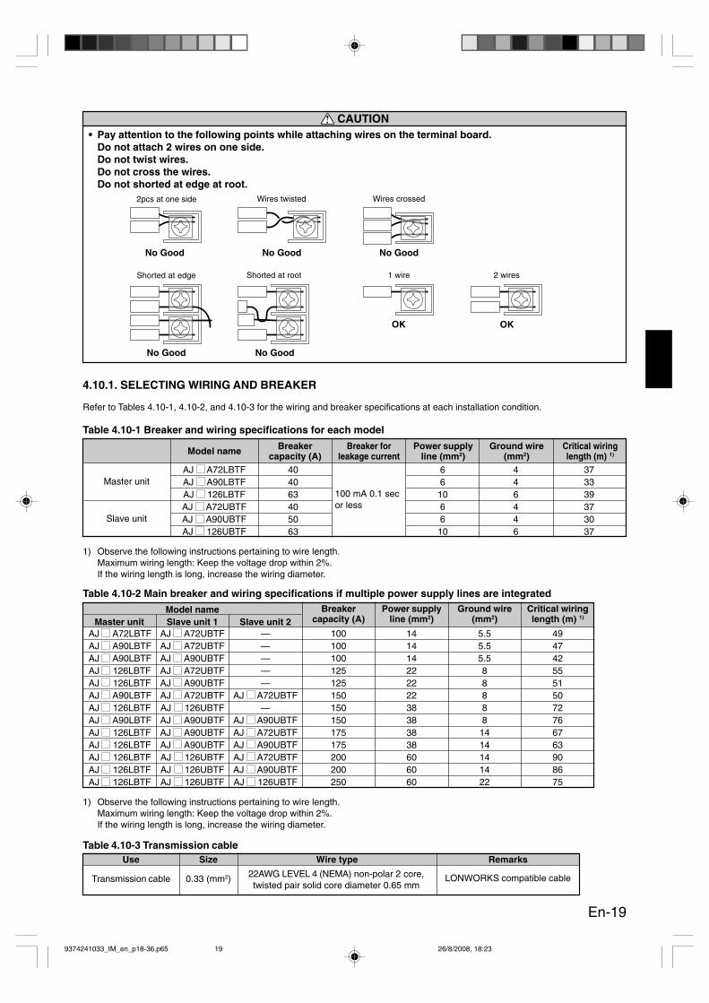
4.10.1. SELECTING WIRING AND BREAKER
Refer to Tables 4.10-1, 4.10-2, and 4.10-3 for the wiring and breaker specifications at each installation condition.
Table 4.10-1 Breaker and wiring specifications for each model
1) Observe the following instructions pertaining to wire length.Maximum wiring length: Keep the voltage drop within 2%.If the wiring length is long, increase the wiring diameter.
Master unitAJ A72LBTF 40 6 4 37AJ A90LBTF 40 6 4 33AJ 126LBTF 63 10 6 39
Slave unitAJ A72UBTF 40 6 4 37AJ A90UBTF 50 6 4 30AJ 126UBTF 63 10 6 37
Model name Breakercapacity (A)
Power supplyline (mm2)
Ground wire(mm2)
Critical wiringlength (m) 1)
Table 4.10-3 Transmission cableUse Size Wire type Remarks
LONWORKS compatible cable22AWG LEVEL 4 (NEMA) non-polar 2 core,twisted pair solid core diameter 0.65 mm
Transmission cable 0.33 (mm2)
Table 4.10-2 Main breaker and wiring specifications if multiple power supply lines are integrated
AJ A72LBTF AJ A72UBTF — 100 14 5.5 49AJ A90LBTF AJ A72UBTF — 100 14 5.5 47AJ A90LBTF AJ A90UBTF — 100 14 5.5 42AJ 126LBTF AJ A72UBTF — 125 22 8 55AJ 126LBTF AJ A90UBTF — 125 22 8 51AJ A90LBTF AJ A72UBTF AJ A72UBTF 150 22 8 50AJ 126LBTF AJ 126UBTF — 150 38 8 72AJ A90LBTF AJ A90UBTF AJ A90UBTF 150 38 8 76AJ 126LBTF AJ A90UBTF AJ A72UBTF 175 38 14 67AJ 126LBTF AJ A90UBTF AJ A90UBTF 175 38 14 63AJ 126LBTF AJ 126UBTF AJ A72UBTF 200 60 14 90AJ 126LBTF AJ 126UBTF AJ A90UBTF 200 60 14 86AJ 126LBTF AJ 126UBTF AJ 126UBTF 250 60 22 75
Breakercapacity (A)
Power supplyline (mm2)
Ground wire(mm2)
Critical wiringlength (m) 1)
Model nameMaster unit Slave unit 1 Slave unit 2
1) Observe the following instructions pertaining to wire length.Maximum wiring length: Keep the voltage drop within 2%.If the wiring length is long, increase the wiring diameter.
Breaker forleakage current
100 mA 0.1 secor less
CAUTION• Pay attention to the following points while attaching wires on the terminal board.
Do not attach 2 wires on one side.Do not twist wires.Do not cross the wires.Do not shorted at edge at root.
No Good
No Good No Good
No GoodNo Good
2pcs at one side Wires twisted Wires crossed
Shorted at edge Shorted at root
OK
1 wire
OK
2 wires
9374241033_IM_en_p18-36.p65 26/8/2008, 18:2319
En-20
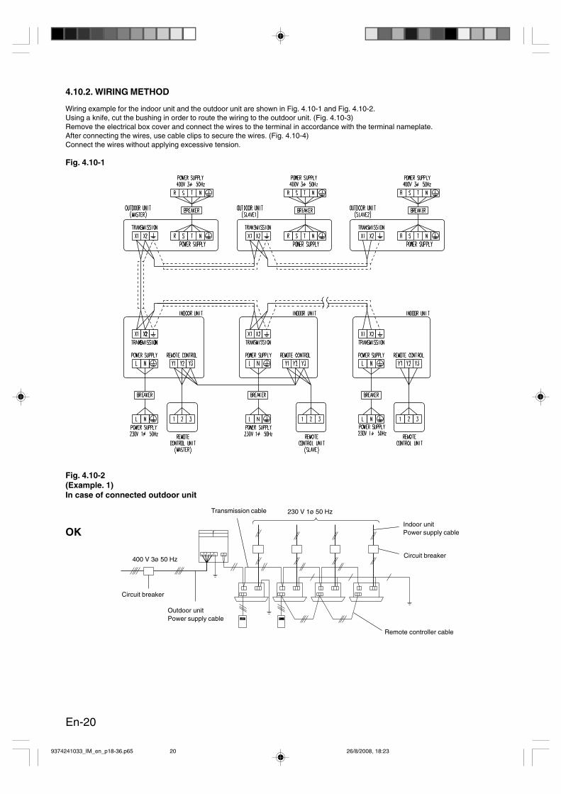
Wiring example for the indoor unit and the outdoor unit are shown in Fig. 4.10-1 and Fig. 4.10-2.Using a knife, cut the bushing in order to route the wiring to the outdoor unit. (Fig. 4.10-3)Remove the electrical box cover and connect the wires to the terminal in accordance with the terminal nameplate.After connecting the wires, use cable clips to secure the wires. (Fig. 4.10-4)Connect the wires without applying excessive tension.
4.10.2. WIRING METHOD
Fig. 4.10-2(Example. 1)In case of connected outdoor unit
400 V 3ø 50 Hz
Circuit breaker
Outdoor unitPower supply cable
Transmission cable 230 V 1ø 50 Hz
Indoor unitPower supply cable
Circuit breaker
Remote controller cable
OK
Fig. 4.10-1
9374241033_IM_en_p18-36.p65 26/8/2008, 18:2320
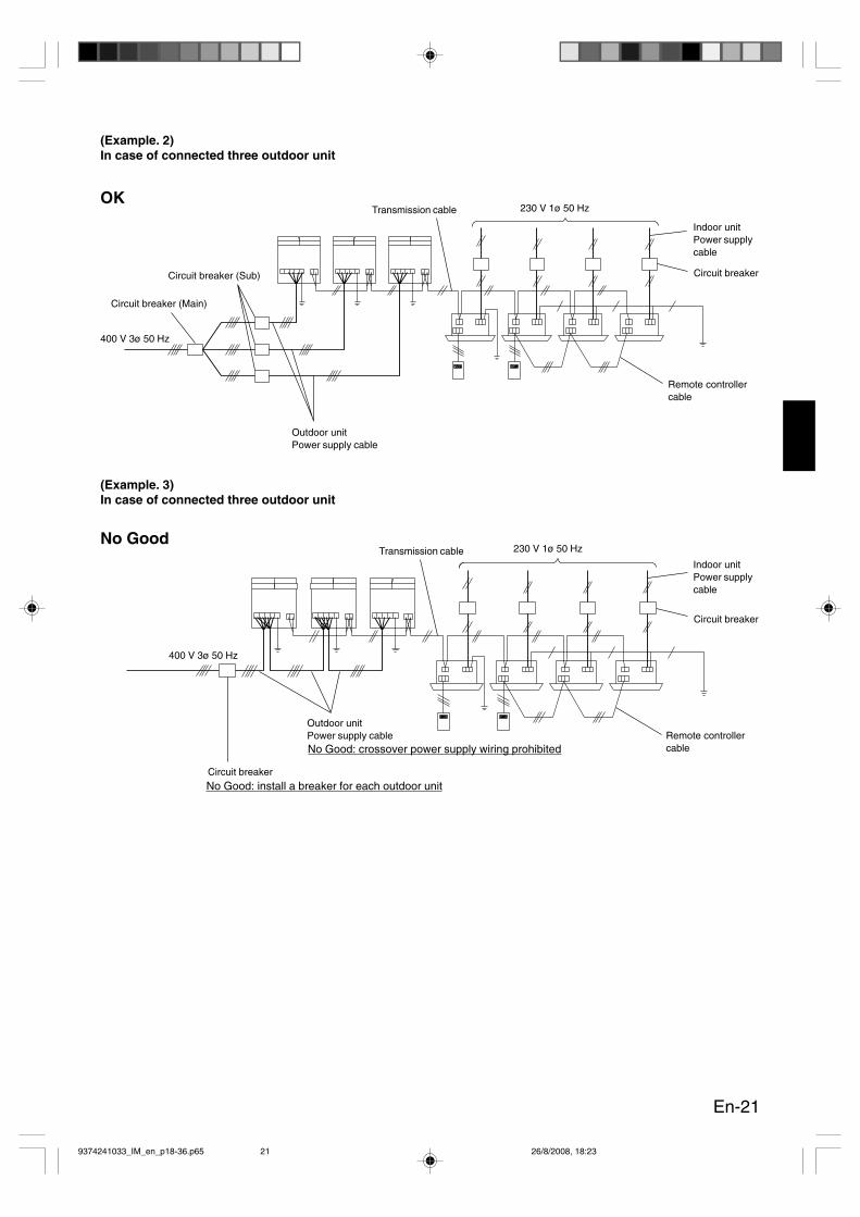
En-21
(Example. 2)In case of connected three outdoor unit
Circuit breaker (Sub)
Circuit breaker (Main)
400 V 3ø 50 Hz
Transmission cable
Outdoor unitPower supply cable
230 V 1ø 50 Hz
Indoor unitPower supplycable
Circuit breaker
Remote controllercable
OK
Remote controllercable
(Example. 3)In case of connected three outdoor unit
No Good
400 V 3ø 50 Hz
Circuit breaker
Outdoor unitPower supply cable
No Good: install a breaker for each outdoor unit
No Good: crossover power supply wiring prohibited
Transmission cable 230 V 1ø 50 Hz
Indoor unitPower supplycable
Circuit breaker
9374241033_IM_en_p18-36.p65 26/8/2008, 18:2321

En-22
Fig. 4.10-4
Distance from termination resistor (m)0 ~100 ~ 200 ~ 300 ~400 ~500
0 ~ 50A short circuit somewhere or 2 or
more termination resistors are connected5060708090100110120130140150160170180
190 ~ Faulty contact or wiring length over 500 m
1K ~∞Faulty contact, open circuit, or no
termination resistor
App
roxi
mat
e re
sist
ance
(Ω
)
Table. 4.10-4Resistance measurement of transmission line (Measure withbreaker OFF)Upon completion of transmission cable wiring, measure the resis-tance of both end of transmission cable of the unit.This resistance (refer to“4.11.4.”) shows Table 4.10-4 value de-pending on the distance from the unit (Outdoor unit or Signalamplifier) on which the terminal resistor was installed. Please notethat these values are approximate.Do not turn on the power if the resistance value is abnormal.It may break Transmission PCB.
Shielding process of transmission lineShield wires at the both end of transmission line shall be securedto each unit’s frame ground with screw. Be careful not to tightenthe screw too much. If it is tightened excessively, an open circuitor breakage of terminal block may occur.
Control boxmetal cover
Transmission cable(Indoor unit and outdoorunit connection cable)
Bush
Power supply cord
Power terminal board
Transmissionterminal board
Ring torqueterminal :M8
70 ~
80
mm
Power supplycable 90
~ 1
00 m
m
40 m
m o
r m
ore
Transmissioncable
30 m
m Cable clip
Power supplycable
Transmission cord
Controlbox
Cordclamp
Binder C
Binder C
Transmissioncable
For 2 transmissionlines
For a single transmission line
Use binder C to secure the 2transmission lines and thecord clamp.
* Use a ring torque terminals to connect the wires to the power terminal board.
Binder C
Fig. 4.10-3
9374241033_IM_en_p18-36.p65 26/8/2008, 18:2322
En-23
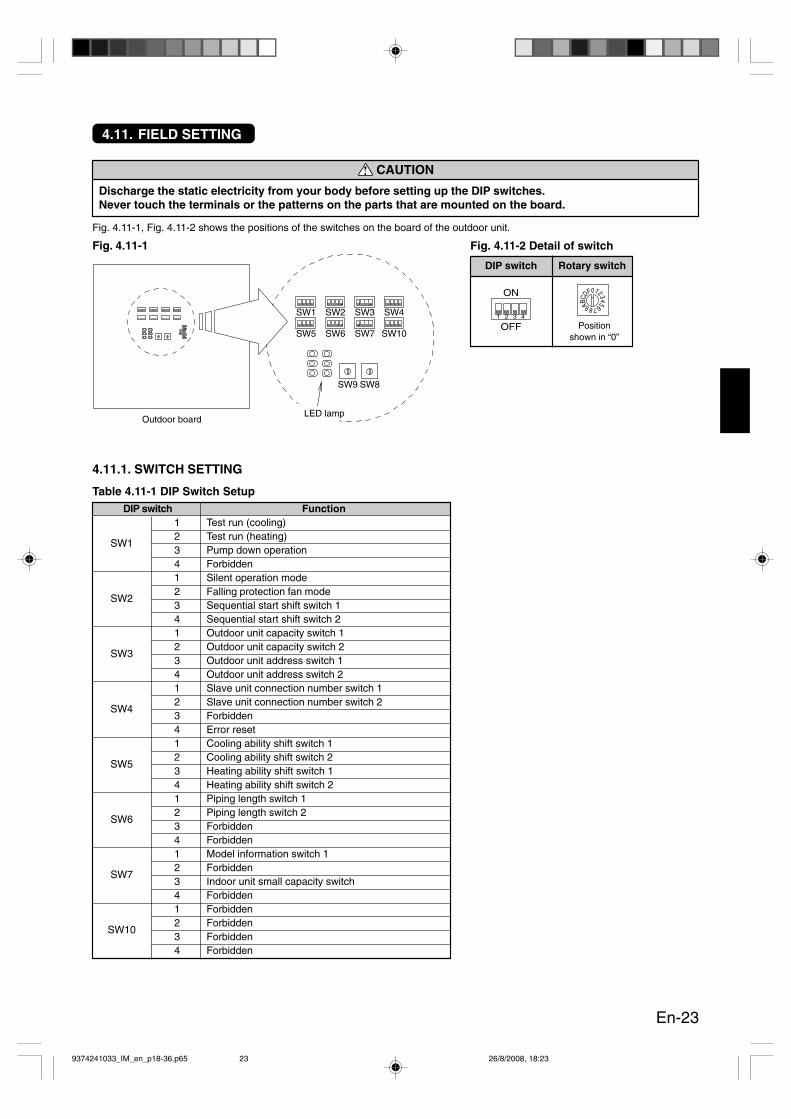
4.11. FIELD SETTING
CAUTION
Discharge the static electricity from your body before setting up the DIP switches.Never touch the terminals or the patterns on the parts that are mounted on the board.
Fig. 4.11-1, Fig. 4.11-2 shows the positions of the switches on the board of the outdoor unit.
4.11.1. SWITCH SETTING
DIP switch Function
SW1
1 Test run (cooling)2 Test run (heating)3 Pump down operation4 Forbidden
SW2
1 Silent operation mode2 Falling protection fan mode3 Sequential start shift switch 14 Sequential start shift switch 2
SW3
1 Outdoor unit capacity switch 12 Outdoor unit capacity switch 23 Outdoor unit address switch 14 Outdoor unit address switch 2
SW4
1 Slave unit connection number switch 12 Slave unit connection number switch 23 Forbidden4 Error reset
SW5
1 Cooling ability shift switch 12 Cooling ability shift switch 23 Heating ability shift switch 14 Heating ability shift switch 2
SW6
1 Piping length switch 12 Piping length switch 23 Forbidden4 Forbidden
SW7
1 Model information switch 12 Forbidden3 Indoor unit small capacity switch4 Forbidden
SW10
1 Forbidden2 Forbidden3 Forbidden4 Forbidden
Table 4.11-1 DIP Switch Setup
LED lamp
SW1 SW2 SW3 SW4
SW5 SW6 SW7
SW9 SW8
SW10
Outdoor board
Fig. 4.11-1
ON
OFF1 2 3 4
0FDCB A9876543
21
Fig. 4.11-2 Detail of switch
DIP switch Rotary switch
Positionshown in “0”
9374241033_IM_en_p18-36.p65 26/8/2008, 18:2323

En-24
4.11.2. FIELD SETTING
The following describes the switch functions and setups that are required for installing an outdoor unit.
1. SW1 SettingSW1-1, 1-2 (Test run)The setting SW1 is only performed on the master unit.There is no need to make this setting on the slave unit.* For details on the master and slave units, refer to page 1.
SW1-3 (Pump down)For the pump down method, refer to “8. PUMP DOWN” .
2. SW2 SettingSW2-1 (Silent operation mode)The operating mode can be switched to this mode for reducednoise during operation of the outdoor unit, such as at night.The setting of SW2-1 must be done on both master and slaveunits.
SW2-2 (Snow fall protection fan mode)When this is set, the fan for the outdoor unit is operated peri-odically even when the compressor is stopped to prevent theunit from becoming covered with snow.The setting of SW2-2 must be done on both master and slaveunits.
SW2-3, 2-4 (Sequential start shift timing)The timing of the start-up of the outdoor unit can be delayedby several seconds with this setting.The setting SW2-3, 2-4 is only performed on the master unit.There is no need to make this setting on the slave unit.* This feature is useful for limiting the start-up current when
multiple outdoor units are installed and started at the sametime.
3. SW3 SettingSW3-1, 3-2 (Outdoor model)Never change the DIP SW3-1, 3-2 which are set up at fac-tory.
SW3-3, 3-4 (Outdoor unit address)The setting of SW3-3, 3-4 is to be done when installing Slave 2.There is no need to make this setting on the master unit.* This setting is only enabled when the power is turned on.
SW1-1 SW1-2 Control mode RemarksOFF OFF Normal (Factory setting)ON OFF Test run (Cooling)OFF ON Test run (Heating)ON ON Normal
Table 4.11-2 DIP SW1-1, 1-2 setting
Refer toChapter “6”for the testrun methods.
Table 4.11-4 DIP SW2-1 setting
Table 4.11-5 DIP SW2-2 settingSW2-2 Snow fall protection fan modeOFF Release (Factory setting)ON Operate
SW2-3 SW2-4 Sequential start modeOFF OFF Normal (Factory setting)OFF ON 21 second delayON OFF 42 second delayON ON 63 second delay
Table 4.11-6 DIP SW2-3, 2-4 setting
SW3-3 SW3-4 Remarks
OFF OFF 0 (Factory setting) Master unitOFF ON 1 (Factory setting) Slave unit 1ON OFF 2 Slave unit 2ON ON Forbidden
Table 4.11-8 DIP SW3-3, 3-4 settingOutdoor unit
address
Table 4.11-3 DIP SW1-3 setting
SW1-3Pump Down
RemarksSetting (reference)
OFF (Factory setting) Release ON → OFFON Operate OFF → ON
Table 4.11-7 DIP SW3-1, 3-2 settingSW3-1 SW3-2 Outdoor Unit ModelOFF OFF AJ A72OFF ON AJ A90ON OFF AJ 126ON ON Forbidden
SW2-1 Silent operation modeOFF (Factory setting) Release
ON Operate
9374241033_IM_en_p18-36.p65 26/8/2008, 18:2324
En-25
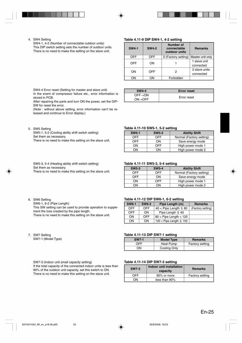
Table 4.11-9 DIP SW4-1, 4-2 setting
Table 4.11-12 DIP SW6-1, 6-2 settingSW6-1 SW6-2 Pipe Length (m) RemarksOFF OFF 40 < Pipe Length <= 80 (Factory setting)OFF ON Pipe Length <= 40ON OFF 80 < Pipe Length < 120ON ON 120 < Pipe Length <= 150
4. SW4 SettingSW4-1, 4-2 (Number of connectable outdoor units)This DIP switch setting sets the number of outdoor units.There is no need to make this setting on the slave unit.
SW4-4 Error reset (Setting for master and slave unit)In the event of compressor failure etc., error information isstored in PCB.After repairing the parts and turn ON the power, set the DIP-SW for reset the error.(Note : without above setting, error information can’t be re-leased and continue to Error display.)
5. SW5 SettingSW5-1, 5-2 (Cooling ability shift switch setting)Set them as necessary.There is no need to make this setting on the slave unit.
SW5-3, 5-4 (Heating ability shift switch setting)Set them as necessary.There is no need to make this setting on the slave unit.
6. SW6 SettingSW6-1, 6-2 (Pipe Length)This SW setting can be used to provide operation to supple-ment the loss created by the pipe length.There is no need to make this setting on the slave unit.
7. SW7 SettingSW7-1 (Model Type)
SW7-3 (Indoor unit small capacity setting)If the total capacity of the connected indoor units is less than90% of the outdoor unit capacity, set this switch to ON.There is no need to make this setting on the slave unit.
Table 4.11-10 SW5-1, 5-2 settingSW5-1 SW5-2 Ability ShiftOFF OFF Normal (Factory setting)OFF ON Save energy modeON OFF High power mode 1ON ON High power mode 2
Table 4.11-11 SW5-3, 5-4 settingSW5-3 SW5-4 Ability ShiftOFF OFF Normal (Factory setting)OFF ON Save energy modeON OFF High power mode 1ON ON High power mode 2
Table 4.11-13 DIP SW7-1 settingSW7-1 Model Type RemarksOFF Heat Pump Factory settingON Cooling Only
SW4-1 SW4-2 Remarks
OFF OFF 0 (Factory setting) Master unit only
OFF ON 1
ON OFF 2
ON ON Forbidden
Number ofconnectable
outdoor units
1 slave unitconnected2 slave unitsconnected
Table 4.11-14 DIP SW7-3 setting
OFF 90% or more Factory settingON less than 90%
SW7-3Indoor unit installation
capacityRemarks
SW4-4 Error resetOFF→ON
Error resetON→OFF
9374241033_IM_en_p18-36.p65 26/8/2008, 18:2325
En-26
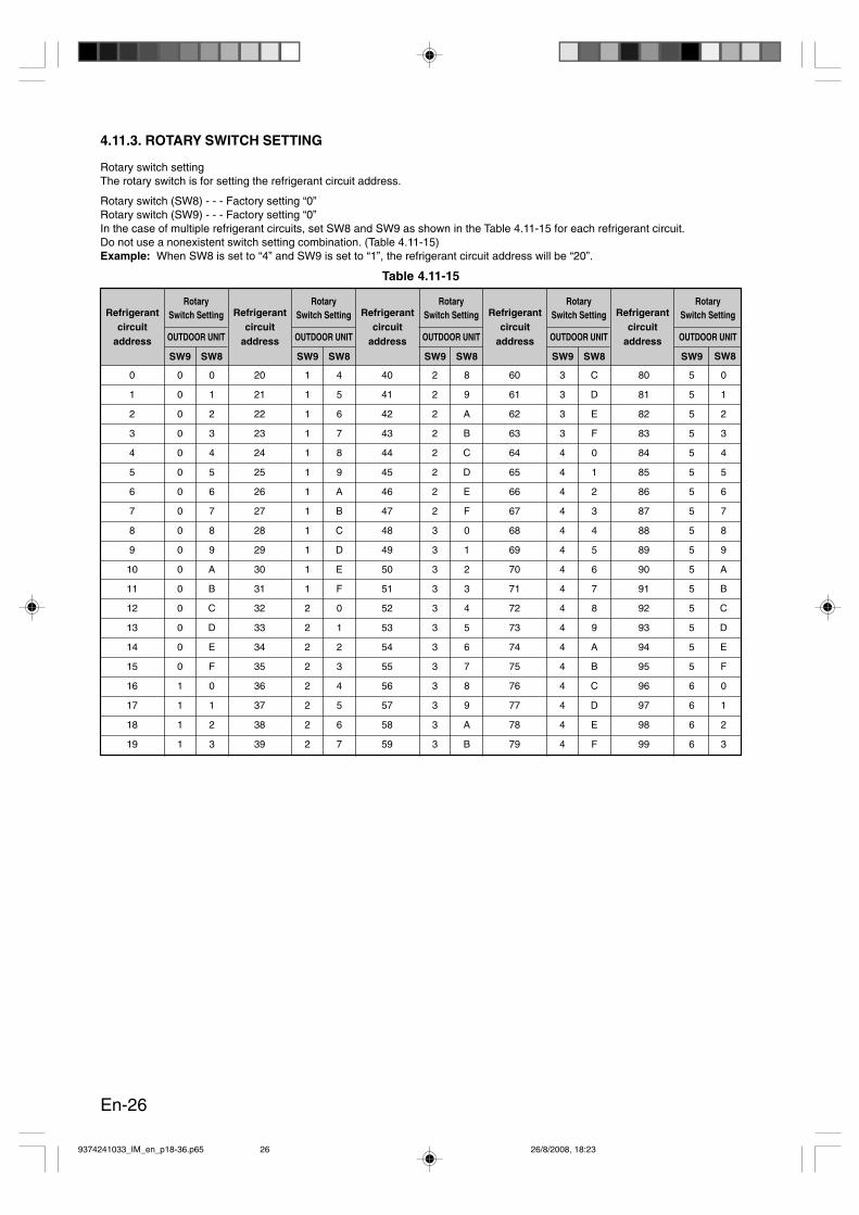
4.11.3. ROTARY SWITCH SETTING
Rotary switch settingThe rotary switch is for setting the refrigerant circuit address.
Rotary switch (SW8) - - - Factory setting “0”Rotary switch (SW9) - - - Factory setting “0”In the case of multiple refrigerant circuits, set SW8 and SW9 as shown in the Table 4.11-15 for each refrigerant circuit.Do not use a nonexistent switch setting combination. (Table 4.11-15)Example: When SW8 is set to “4” and SW9 is set to “1”, the refrigerant circuit address will be “20”.
0 0 0 20 1 4 40 2 8 60 3 C 80 5 0
1 0 1 21 1 5 41 2 9 61 3 D 81 5 1
2 0 2 22 1 6 42 2 A 62 3 E 82 5 2
3 0 3 23 1 7 43 2 B 63 3 F 83 5 3
4 0 4 24 1 8 44 2 C 64 4 0 84 5 4
5 0 5 25 1 9 45 2 D 65 4 1 85 5 5
6 0 6 26 1 A 46 2 E 66 4 2 86 5 6
7 0 7 27 1 B 47 2 F 67 4 3 87 5 7
8 0 8 28 1 C 48 3 0 68 4 4 88 5 8
9 0 9 29 1 D 49 3 1 69 4 5 89 5 9
10 0 A 30 1 E 50 3 2 70 4 6 90 5 A
11 0 B 31 1 F 51 3 3 71 4 7 91 5 B
12 0 C 32 2 0 52 3 4 72 4 8 92 5 C
13 0 D 33 2 1 53 3 5 73 4 9 93 5 D
14 0 E 34 2 2 54 3 6 74 4 A 94 5 E
15 0 F 35 2 3 55 3 7 75 4 B 95 5 F
16 1 0 36 2 4 56 3 8 76 4 C 96 6 0
17 1 1 37 2 5 57 3 9 77 4 D 97 6 1
18 1 2 38 2 6 58 3 A 78 4 E 98 6 2
19 1 3 39 2 7 59 3 B 79 4 F 99 6 3
Table 4.11-15
Refrigerantcircuit
address
RotarySwitch Setting
OUTDOOR UNIT
SW9 SW8
Refrigerantcircuit
address
RotarySwitch Setting
OUTDOOR UNIT
SW9 SW8
Refrigerantcircuit
address
RotarySwitch Setting
OUTDOOR UNIT
SW9 SW8
Refrigerantcircuit
address
RotarySwitch Setting
OUTDOOR UNIT
SW9 SW8
Refrigerantcircuit
address
RotarySwitch Setting
OUTDOOR UNIT
SW9 SW8
9374241033_IM_en_p18-36.p65 26/8/2008, 18:2326

En-27
CN22
E1CN
20CN
22CN
2
The terminal resistor is provided with the master unit.When there are multiple master units connected by a communi-cation cable, attach the terminal resistor to CN22 on only one ofthose master units.* Refer to the installation instruction sheet provided with the sig-
nal amplifier when mounting a signal amplifier.
CAUTION
Make sure to install a termination resistor as speci-fied. Install 1 termination resistor within 500 metersof the overall length of the transmission line. Installthe termination resistor as shown in Fig. 4.11-3.
• If multiple terminal resistors are installed, the en-tire transmission system may break.
• If no resistor is installed, a transmission failure mayoccur.
Terminal resistor
Don’t connectterminal resistor.
Master 1Slave 1
Terminal resistor
Master 1Slave 1Slave 2
Outdoor board
Refrigerant circuit address 1
Refrigerant circuit address 2
Fig. 4.11-3
4.11.4. TERMINAL RESISTOR SETTING
9374241033_IM_en_p18-36.p65 26/8/2008, 18:2327
En-28
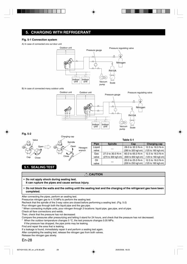
Fig. 5-1 Connection system
Indoorunit
Indoorunit
R410A
Nitrogen
Indoorunit
Indoorunit
R410A
Nitrogen
A) In case of connected one out door unit
Pressure gaugePressure regulating valve
Vaccumpump
Scale
Pressure gaugePressure regulating valve
Vaccumpump
Scale
B) In case of connected many outdoor units
Outdoor unit
Outdoor unit Outdoor unit
Fig. 5-2
Hexagonwrench
Spindle
Open
Close
Valve
Open
CloseCap
CAUTION
• Do not apply shock during sealing test.It can rupture the pipes and cause serious injury.
• Do not block the walls and the ceiling until the sealing test and the charging of the refrigerant gas have beencompleted.
Table 5-1Charging cap
PipeLiquidvalveGasvalveOil
valve
Spindle
—
27.0 to 30.0 N·m (270 to 300 kgf·cm)
—
Cap28.0 to 32.0 N·m(280 to 320 kgf·cm)60.0 to 65.0 N·m (600 to 650 kgf·cm)20.0 to 25.0 N·m(200 to 250 kgf·cm)
Charging cap12.5 to 16.0 N·m(125 to 160 kgf·cm)12.5 to 16.0 N·m (125 to 160 kgf·cm)12.5 to 16.0 N·m(125 to 160 kgf·cm)
5. CHARGING WITH REFRIGERANT
5.1. SEALING TEST
After connecting the pipes, perform an sealing test.Pressurize nitrogen gas to 4.15 MPa to perform the sealing test.Recheck that the spindle of the 3-way valve are closed before performing a sealing test. (Fig. 5-2)Pour nitrogen gas through both the liquid pipe and the gas pipe.* When connecting multiple units, pour nitrogen through 3 locations: liquid pipe, gas pipe, and oil pipe.Check all flare connections and welds.Then, check that the pressure has not decreased.Compare the pressures after pressurizing and letting it stand for 24 hours, and check that the pressure has not decreased.* When the outdoor temperature changes 5 °C, the test pressure changes 0.05 MPa.
If the pressure has dropped, the pipe joints may be leaking.Find and repair the area that is leaking.If a leakage is found, immediately repair it and perform a sealing test again.After completing the sealing test, release the nitrogen gas from both valves.Release the nitrogen gas slowly.
9374241033_IM_en_p18-36.p65 26/8/2008, 18:2328
En-29
5.2. VACCUM PROCESS
CAUTION
• If the system is not evacuated sufficiently, its performance will drop.
• The location from which to evacuate the system differs whether 1 outdoor unit or multiple outdoor units areconnected.
Evacuation procedure• One outdoor unit connected:1. Remove the flares at the gas pipe and liquid pipe, and make sure the valves are closed.2. Remove the charging cap.3. Connect a vacuum pump and a pressure gauge to a charging hose and connect it to the charging port.4. Evacuate the indoor unit and the pipe joint until the pressure gauge reads –76 cmHg.
Evacuate from both the gas pipe and the liquid pipe.5. Continue evacuating the system for 1 hour after the pressure gauge reads –76 cmHg.6. Remove the charging hose and install the charging cap.
• Multiple outdoor units connected:1. Remove the flares at the gas pipe, liquid pipe, and oil pipe, and make sure the valves are closed.2. Remove the charging cap.3. Connect a vacuum pump and a pressure gauge to a charging hose and connect it to the charging port.4. Evacuate the indoor unit and the pipe joint until the pressure gauge reads –76 cmHg.
Evacuate from 3 locations: the gas pipe, liquid pipe, and oil pipe.5. Continue evacuating the system for 1 hour after the pressure gauge reads –76 cmHg.6. Remove the charging hose and install the charging cap.
5.3. ADDITIONAL CHARGING
CAUTION
• After evacuating the system, add refrigerant.
• Do not charge the system with a refrigerant other than R410A.
• Do not reuse recovered refrigerant.
• Use an electronic scale to measure the charging amount of refrigerant.Adding more refrigerant than the specified amount will cause a malfunction.
• Charge refrigerant using the liquid pipe.Adding refrigerant through the gas pipe will cause a malfunction.
• Add refrigerant by charging the system with the refrigerant in the liquid state. If the refrigerant cylinder isequipped with a siphon, it is not necessary to place the cylinder upright.
Procedure for charging the system with refrigerant1. Remove the charging cap from the liquid pipe.2. Attach a charging hose to the refrigerant cylinder, and connect it to the charging port.3. Add refrigerant by calculating the additional refrigerant volume in accordance with the calculation formula indicated below.4. Remove the charging hose and install the charging cap.5. Remove the body caps (gas pipe, liquid pipe, and oil pipe if multiple units are installed), and open the valves.6. Close the body caps.7. After adding refrigerant, indicate the added charging volume on the unit.
* Tighten the body caps and charging caps to the torque values specified in the Table 4.7-2.To open and close the valves,Use an M4 hexagon wrench for liquid and oil pipes.Use an M10 hexagon wrench for gas pipes.
9374241033_IM_en_p18-36.p65 26/8/2008, 18:2329
En-30
A = + +
B = + + +
+
Total length of
ø19.05 mm
liquid pipe
mkg
× 0.268kg/m
Total length of
ø15.88 mm
liquid pipe
mkg
× 0.178kg/m
Total length of
ø12.70 mm
liquid pipe
mkg
× 0.114kg/m
Total length of
ø9.52 mm
liquid pipe
mkg
× 0.058kg/m
Total length of
ø6.35 mm
liquid pipe
mkg
× 0.021kg/m
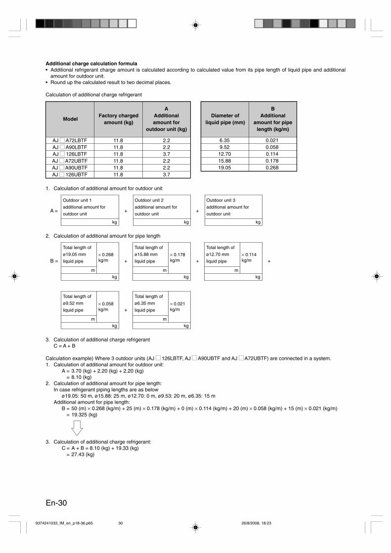
Additional charge calculation formula• Additional refrigerant charge amount is calculated according to calculated value from its pipe length of liquid pipe and additional
amount for outdoor unit.• Round up the calculated result to two decimal places.
Calculation of additional charge refrigerant
1. Calculation of additional amount for outdoor unit
Outdoor unit 1
additional amount for
outdoor unit
kg
Outdoor unit 2
additional amount for
outdoor unit
kg
Outdoor unit 3
additional amount for
outdoor unit
kg
2. Calculation of additional amount for pipe length
3. Calculation of additional charge refrigerantC = A + B
Calculation example) Where 3 outdoor units (AJ 126LBTF, AJ A90UBTF and AJ A72UBTF) are connected in a system.1. Calculation of additional amount for outdoor unit:
A = 3.70 (kg) + 2.20 (kg) + 2.20 (kg)= 8.10 (kg)
2. Calculation of additional amount for pipe length:In case refrigerant piping lengths are as below
ø19.05: 50 m, ø15.88: 25 m, ø12.70: 0 m, ø9.53: 20 m, ø6.35: 15 mAdditional amount for pipe length:
B = 50 (m) × 0.268 (kg/m) + 25 (m) × 0.178 (kg/m) + 0 (m) × 0.114 (kg/m) + 20 (m) × 0.058 (kg/m) + 15 (m) × 0.021 (kg/m)= 19.325 (kg)
3. Calculation of additional charge refrigerant:C = A + B = 8.10 (kg) + 19.33 (kg)
= 27.43 (kg)
AJ A72LBTF 11.8 2.2AJ A90LBTF 11.8 2.2AJ 126LBTF 11.8 3.7AJ A72UBTF 11.8 2.2AJ A90UBTF 11.8 2.2AJ 126UBTF 11.8 3.7
ModelFactory charged
amount (kg)
AAdditionalamount for
outdoor unit (kg)
6.35 0.0219.52 0.05812.70 0.11415.88 0.17819.05 0.268
Diameter ofliquid pipe (mm)
BAdditional
amount for pipelength (kg/m)
9374241033_IM_en_p18-36.p65 26/8/2008, 18:2330
En-31
6. TEST RUN
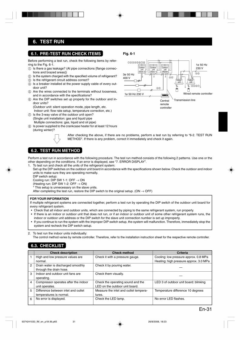
6.1. PRE-TEST RUN CHECK ITEMS
Before performing a test run, check the following items by refer-ring to the Fig. 6-1.1 Is there a gas leakage? (At pipe connections flange connec-
tions and brazed areas)2 Is the system charged with the specified volume of refrigerant?3 Is the refrigerant circuit address correct?4 Is a breaker installed at the power supply cable of every out-
door unit?5 Are the wires connected to the terminals without looseness,
and in accordance with the specifications?6 Are the DIP switches set up properly for the outdoor and in-
door units?(Outdoor unit: silent operation mode, pipe length, etc.Indoor unit: flow rate setup, temperature correction, etc.)
7 Is the 3-way valve of the outdoor unit open?(Single unit installation: gas and liquid pipeMultiple connections: gas, liquid and oil pipe)
8 Is power supplied to the crankcase heater for at least 12 hours(during winter)?
After checking the above, if there are no problems, perform a test run by referring to “6-2. TEST RUNMETHOD”. If there is any problem, correct it immediately and check it again.
Perform a test run in accordance with the following procedure. The test run method consists of the following 2 patterns. Use one or theother depending on the conditions. If an error is displayed, see “7. ERROR DISPLAY”.1. To test run and check all the units of the refrigerant system:
Set up the DIP switches on the outdoor unit board in accordance with the specifications shown below. Check the outdoor and indoorunits to make sure they are operating normally.DIP switch setup:Cooling run: DIP SW 1-1: OFF → ON(Heating run: DIP SW 1-2: OFF → ON)* This setup is unnecessary on the slave units.After completing the test run, restore the DIP switch to the original setup. (ON → OFF)
FOR YOUR INFORMATIONIf multiple refrigerant systems are connected together, perform a test run by operating the DIP switch of the outdoor unit board forevery refrigerant system.• Check that all indoor and outdoor units, which are connected by piping to the same refrigerant system, run properly.• If there is an indoor or outdoor unit that does not run, or if an indoor or outdoor unit of some other refrigerant system runs, the
indoor or outdoor unit address or the DIP switch for the slave unit connection number is set up improperly.• If you continue to run the system with the improper DIP switch setup, the system will malfunction. Therefore, immediately stop the
system and recheck the DIP switch setup.
2. To test run the indoor units individually:The control method varies by remote controller. Therefore, refer to the installation instruction sheet for the respective remote controller.
6.2. TEST RUN METHOD
6.3. CHECKLIST
CriteriaCooling: low pressure approx. 0.8 MPaHeating: high pressure approx. 3.0 MPa
—
—
LED 3 of outdoor unit board: blinking
Temperature difference 10 degrees
No error LED flashes.
1
2
3
4
5
6
Check descriptionHigh and low pressure values arenormal.Drain water is discharged smoothlythrough the drain hose.Indoor and outdoor unit fans areoperating.Compressor operates after the indoorunit operates.Difference between inlet and outlettemperatures is normal.No error is displayed.
Check methodCheck it with a pressure gauge.
Check it by pouring water.
Check them visually.
Check the operating sound and theLED on the outdoor unit board.Measure the inlet and outlet tempera-tures.Check the LED lamp.
Fig. 6-1
Outdoor unit
(Slave 2)
Outdoor unit
(Slave 1)
Outdoor unit
(Master)
Indoor unit
12345678
45
45
45
4567
Indoor unit
3ø 50 Hz400 V
1ø 50 Hz 230 V
1ø 50 Hz230 V
Centralremotecontroller
Wired remote controller
Transmission line
9374241033_IM_en_p18-36.p65 26/8/2008, 18:2331
En-32
OFF
ON
LED 1
LED 2-6
OFF
ON
0.5 sec2 sec
0.5 sec
LED6
LED5
LED4
LED3
LED2
LED1
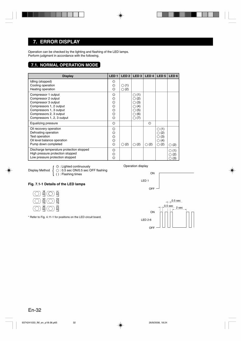
LED 1Display
Idling (stopped)Cooling operationHeating operation
Compressor 1 outputCompressor 2 outputCompressor 3 outputCompressors 1, 2 outputCompressors 1, 3 outputCompressors 2, 3 outputCompressors 1, 2, 3 output
Equalizing pressure
Oil recovery operationDefrosting operationTest operationOil level balance operationPump down completed
Discharge temperature protection stoppedHigh pressure protection stoppedLow pressure protection stopped
LED 2
(1) (2)
(2)
LED 3
(1) (2) (3) (4) (5) (6) (7)
(2)
LED 4
(2)
LED 5
(1) (2) (3) (4) (2)
LED 6
(2)
(1) (2) (3)
Fig. 7.1-1 Details of the LED lamps
* Refer to Fig. 4.11-1 for positions on the LED circuit board.
: Lighted continuouslyDisplay Method : 0.5 sec ON/0.5 sec OFF flashing
( ) : Flashing timesOperation display
7. ERROR DISPLAY
Operation can be checked by the lighting and flashing of the LED lamps.Perform judgment in accordance with the following.
7.1. NORMAL OPERATION MODE
9374241033_IM_en_p18-36.p65 26/8/2008, 18:2432
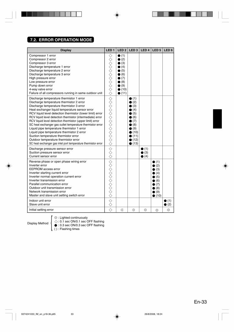
En-33
LED 1Display
Compressor 1 errorCompressor 2 errorCompressor 3 errorDischarge temperature 1 errorDischarge temperature 2 errorDischarge temperature 3 errorHigh pressure errorLow pressure errorPump down error4-way valve errorFailure of all compressors running in same outdoor unit
Discharge temperature thermistor 1 errorDischarge temperature thermistor 2 errorDischarge temperature thermistor 3 errorHeat exchanger liquid temperature sensor errorRCV liquid level detection thermistor (lower limit) errorRCV liquid level detection thermistor (intermediate) errorRCV liquid level detection thermistor (upper limit) errorSC heat exchanger gas outlet temperature thermistor errorLiquid pipe temperature thermistor 1 errorLiquid pipe temperature thermistor 2 errorSuction temperature thermistor errorOutdoor temperature thermistor errorSC heat exchanger gas inlet port temperature thermistor error
Discharge pressure sensor errorSuction pressure sensor errorCurrent sensor error
Reverse phase or open phase wiring errorInverter errorEEPROM access errorInverter starting current errorInverter normal operation current errorInverter transmission errorParallel communication errorOutdoor unit transmission errorNetwork transmission errorMaster and slave unit setting switch error
Indoor unit errorSlave unit error
Initial setting error
LED 2
(1) (2) (3) (4) (5) (6) (7) (8) (9) (10) (11)
LED 3
(1) (2) (3) (4) (5) (6) (7) (8) (9) (10) (11) (12) (13)
LED 4
(1) (3) (4)
LED 5
(1) (2) (3) (4) (5) (6) (7) (8) (9) (10)
LED 6
(1) (2)
7.2. ERROR OPERATION MODE
: Lighted continuously: 0.1 sec ON/0.1 sec OFF flashing
Display Method: 0.3 sec ON/0.3 sec OFF flashing
( ) : Flashing times
9374241033_IM_en_p18-36.p65 26/8/2008, 18:2433

En-34
CAUTION
Do not reuse the refrigerant that has been recovered by the recovery pump.
To prevent the discharge of the refrigerant into the atmosphere, follow the procedure indicated below to recover the refrigerant from anoutdoor unit before moving or discarding the unit. Up to approximately 20 kg can be recovered per outdoor unit. If the volume of therefrigerant to be recovered is large, recover it into a refrigerant recovery cylinder while measuring the weight of the refrigerant.
Fig. 8-1 Connecting systemA) In case of connected outdoor unit B) In case of connected many outdoor units
Single unit InstallationPump down method 1 (DIP switch method)1. Fully close the 3-way valve at the liquid pipe.2. Set the DIP switch 1-3 on the outdoor unit board “OFF → ON”.
The unit will start automatically in the cooling mode.3. When the pump down is completed, the LED lamps will flash
at LED 2 to 6.4. After the LED lamps flash, fully close the 3-way valve at the
gas pipe within 2 minutes, otherwise the compressor may bedamaged.
5. Restore the DIP switch to the original setup. (ON → OFF)
Pump down method 2 (manual method)1. Connect the charge hose of the manifold gauge to the charge
port of the 3-way valve at the gas pipe. Open the pressurereduction valve slightly to purge the air from the charge hose.
2. Fully close the 3-way valve at the liquid pipe.3. Perform a test run in the cooling mode.
* Set the DIP switch SW1-1 to “OFF → ON”.4. When the pressure gauge reads between 0.05 and 0 MPa,
fully close the 3-way valve at the gas pipe and stop the runpromptly.Set the DIP switch SW1-1 to “ON → OFF”.If the unit continues to run with the pressure at 0 MPa, thecompressor may be damaged.
In case there is too much refrigerant1. Connect a gas cylinder to the charge port at the liquid pipe.2. Perform a test run in the cooling mode.
* Set the DIP switch SW1-1 to “OFF → ON”.* If the refrigerant is difficult to recover, fully close the 3-way
valve at the liquid pipe.3. After recovering the refrigerant using the gas cylinder, stop
the run.Set the DIP switch SW1-1 to “ON → OFF”.
4. Perform the pump down operation according to the methoddescribe above.
Indoorunit
Outdoor unit
Indoorunit
Empty cylinder
Scale
Pressuregauge Outdoor unitOutdoor unit
Empty cylinder
Scale
Pressuregauge
Indoorunit
Indoorunit
Multiple connectionsPump down method 1 (DIP switch method)1. Fully close the 3-way valves at the liquid pipes.
Fully close the 3-way valves at the oil pipes of the slave units.* Leave only the 3-way valve at the oil pipe of the master unit
fully open.2. Set the DIP switch 1-3 on the outdoor unit board “OFF → ON”.
(the master unit board)The unit will start automatically in the cooling mode.
3. When the pump down is completed, the LED lamps will flashat LED 2 to 6.
4. After the LED lamps flash, fully close the 3-way valve at thegas pipes and the 3-way valve at the oil pipe on the masterunit within 2 minutes.Restore the DIP switch to the original setup. (ON → OFF)If the 3-way valves are open for more than 2 minutes, the com-pressor may be damaged.* If it will be difficult to close the 3-way valves for all units
during the 2 minutes while the LED lamps are flashing, closethe valves a little before performing the pump down opera-tion.
Pump down method 2 (manual method)1. Connect the charge hose of the manifold gauge to the charge
port of the 3-way valve at the gas pipe. Open the pressurereduction valve slightly to purge the air from the charge hose.
2. Fully close the 3-way valves at the liquid pipes.Fully close the 3-way valves at the oil pipes of the slave units.* Leave only the 3-way valve at the oil pipe of the master unit
fully open.3. Perform a test run in the cooling mode. (the master unit board)
* Set the DIP switch SW1-1 to “OFF → ON”.4. When the pressure gauge reads between 0.05 and 0 MPa,
fully close the 3-way valves at the gas pipes and the 3-wayvalves at the oil pipes on all units and stop the run promptly.Set the DIP switch SW1-1 to “ON → OFF”.If the unit continues to run with the pressure at 0 MPa, thecompressor may be damaged.
In case there is too much refrigerant1. Connect a gas cylinder to the charge port at the liquid pipe.2. Perform a test run in the cooling mode. (the master unit board)
* Set the DIP switch SW1-1 to “OFF → ON”.* If the refrigerant is difficult to recover, fully close the 3-way
valve at the liquid pipe.3. After recovering the refrigerant using the gas cylinder, stop
the run.Set the DIP switch SW1-1 to “ON → OFF”.
4. Perform the pump down operation according to the methoddescribe above.
8. PUMP DOWN
9374241033_IM_en_p18-36.p65 26/8/2008, 18:2434

En-35
1. SEPARATION TUBE KITTable 9-1 shows a outdoor unit branch kit that is used for installing multiple outdoor units. Table 9-2 shows separation tubes used forconnection between outdoor and indoor units. Refer to the installation instruction sheet for the outdoor unit branch kit and theseparation tubes for installation specifications.
9. OPTION PARTS
CAUTION
Listed below are option parts used exclusively with the R410A refrigerant.Do not use parts other than those listed below.
Table 9-2 Separation tube selection
Table 9-3 Header selection
2. HEADERA header is used for connecting the indoor units. Refer to the installation instruction sheet for the header for installation specifica-tions.
Table 9-1 Outdoor unit branch kit for installing multiple outdoor unitsOutdoor unit branch kit Total model code of outdoor unit
UTR-CP567LUTR-CP567X ALLUTR-CP567Q
Separation tube Total model code of indoor unitUTR-BP090LUTR-BP090X 90 or lessUTR-BP090QUTR-BP180LUTR-BP180X 91 to 180UTR-BP180QUTR-BP567LUTR-BP567X 181 or moreUTR-BP567Q
Header Total model code6 Branches 8 Branches of outdoor unitUTR-H0906L UTR-H0908L 90 or lessUTR-H1806L UTR-H1808L 91 to 180
9374241033_IM_en_p18-36.p65 26/8/2008, 18:2435
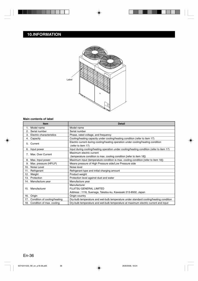
En-36
10.INFORMATION
Item
1. Model name2. Serial number3. Electric characteristics4. Capacity
5. Current
6. Input power
7. Max. Over Current
8. Max. Input power9. Max. pressure (HP/LP)
10. Noise Level11. Refrigerant12. Weight13. Protection14. Manufacture year
15. Manufacturer
16. Origin17. Condition of cooling/heating18. Condition of max. cooling
Detail
Model nameSerial numberPhase, rated voltage, and frequencyCooling/heating capacity under cooling/heating condition (refer to item 17)Electric current during cooling/heating operation under cooling/heating condition (refer to item 17)Input during cooling/heating operation under cooling/heating condition (refer to item 17)Maximum electric current (temperature condition is max. cooling condition [refer to item 18])Maximum input (temperature condition is max. cooling condition [refer to item 18])Means pressure of High Pressure side/Low Pressure sideNoise levelRefrigerant type and initial charging amountProduct weightProtection level against dust and waterManufacture yearManufacturerFUJITSU GENERAL LIMITEDAddress : 1116, Suenaga, Takatsu-ku, Kawasaki 213-8502, JapanOrigin countryDry-bulb temperature and wet-bulb temperature under standard cooling/heating conditionDry-bulb temperature and wet-bulb temperature at maximum electric current and input
Main contents of label
Label
9374241033_IM_en_p18-36.p65 26/8/2008, 18:2436