figure 1 - wiley · fundamentals of electric circuit analysis, by clayton paul figure 1.1...
TRANSCRIPT

Fundamentals of Electric Circuit Analysis, by Clayton Paul
Figure 1.1Illustration of themodeling of a device(a CD amplifier) withan electric circuitmodel.
Fundamentals of Electric Circuit Analysis, by Clayton Paul
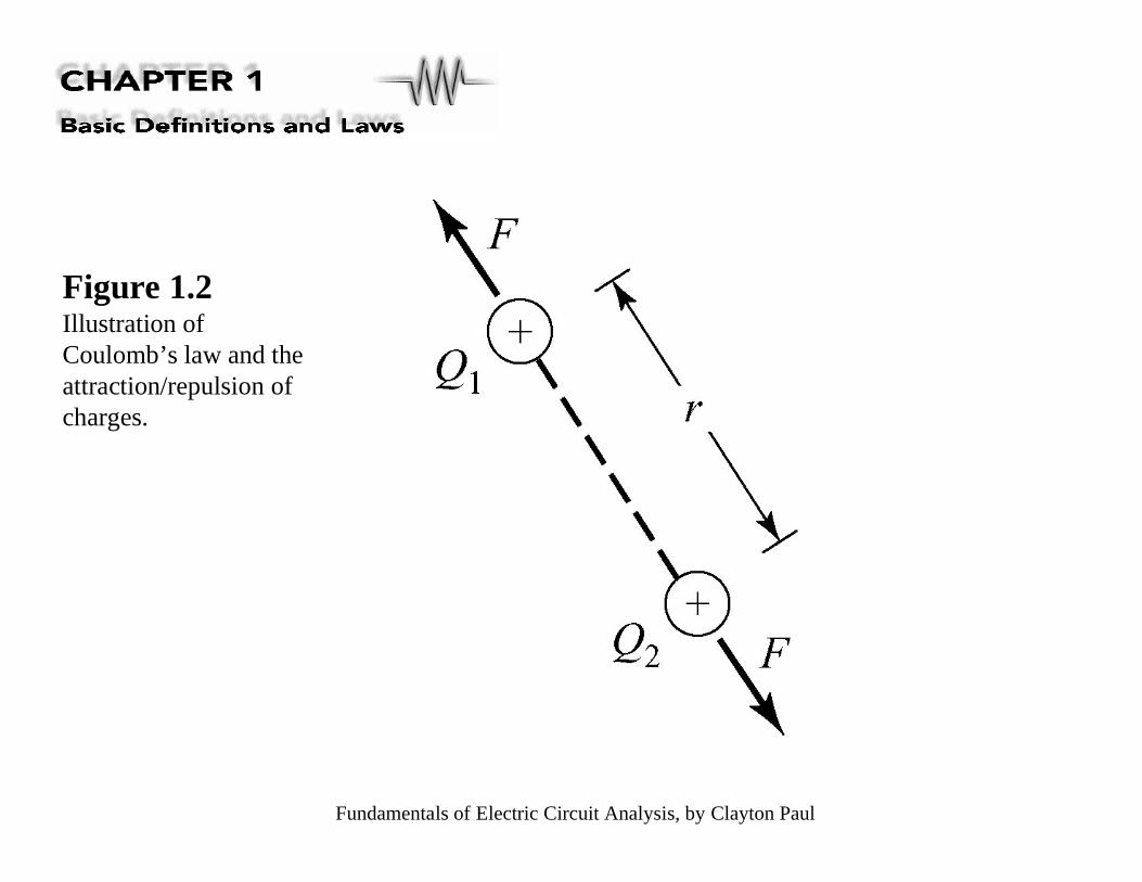
Figure 1.2Illustration ofCoulomb’s law and theattraction/repulsion ofcharges.
Fundamentals of Electric Circuit Analysis, by Clayton Paul
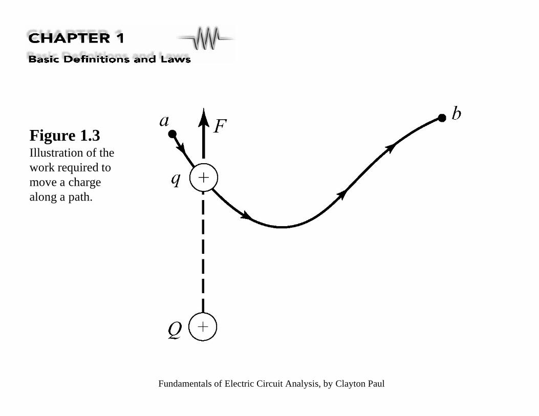
Figure 1.3Illustration of thework required tomove a chargealong a path.
Fundamentals of Electric Circuit Analysis, by Clayton Paul
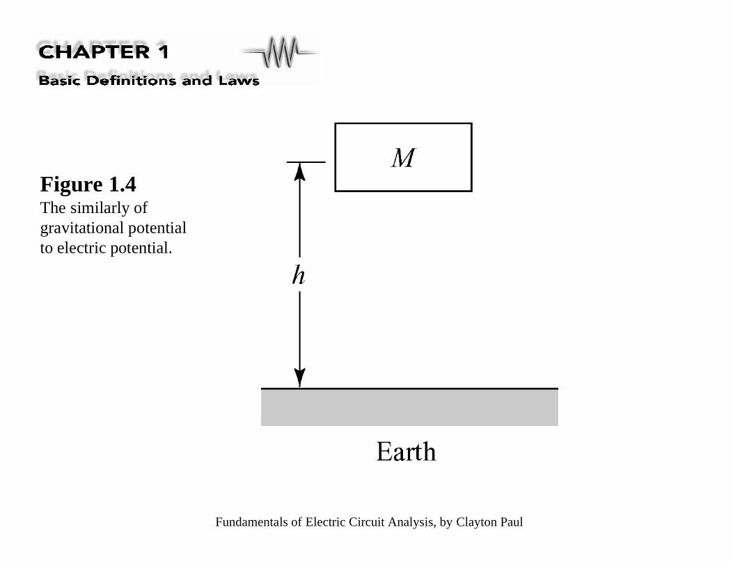
Figure 1.4The similarly ofgravitational potentialto electric potential.
Fundamentals of Electric Circuit Analysis, by Clayton Paul
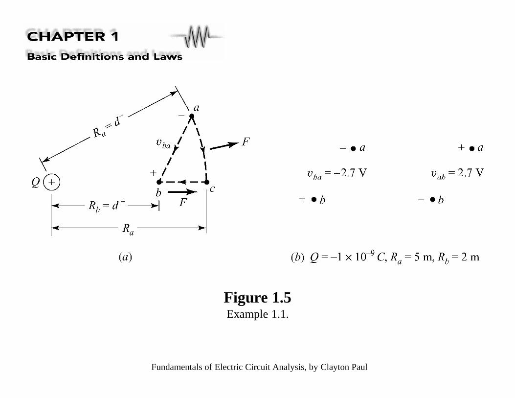
Figure 1.5Example 1.1.
Fundamentals of Electric Circuit Analysis, by Clayton Paul
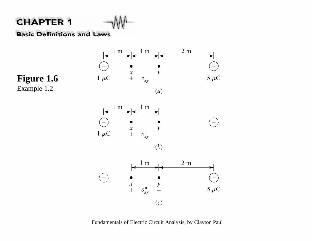
Figure 1.6Example 1.2

Fundamentals of Electric Circuit Analysis, by Clayton Paul
Figure 1.7 Illustration of (a) current as the rate of movement of electric charge, and(b) the magnetic field associated with that charge movement.
Fundamentals of Electric Circuit Analysis, by Clayton Paul
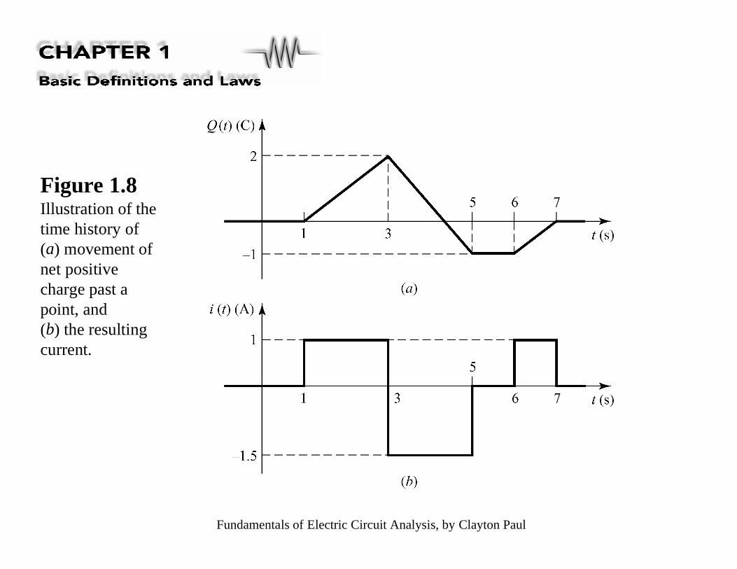
Figure 1.8Illustration of thetime history of(a) movement ofnet positivecharge past apoint, and(b) the resultingcurrent.
Fundamentals of Electric Circuit Analysis, by Clayton Paul
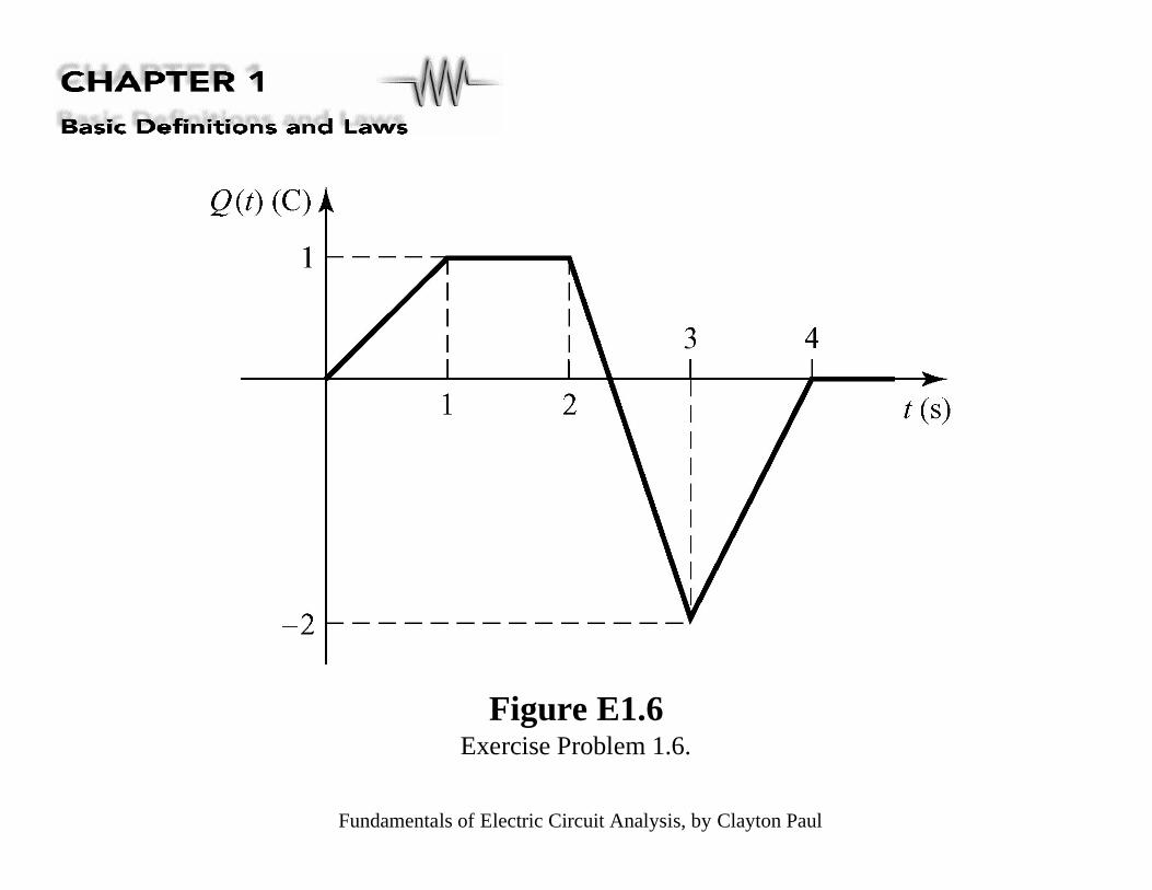
Figure E1.6Exercise Problem 1.6.

Fundamentals of Electric Circuit Analysis, by Clayton Paul
Figure E1.7Exercise Problem 1.7.
Fundamentals of Electric Circuit Analysis, by Clayton Paul
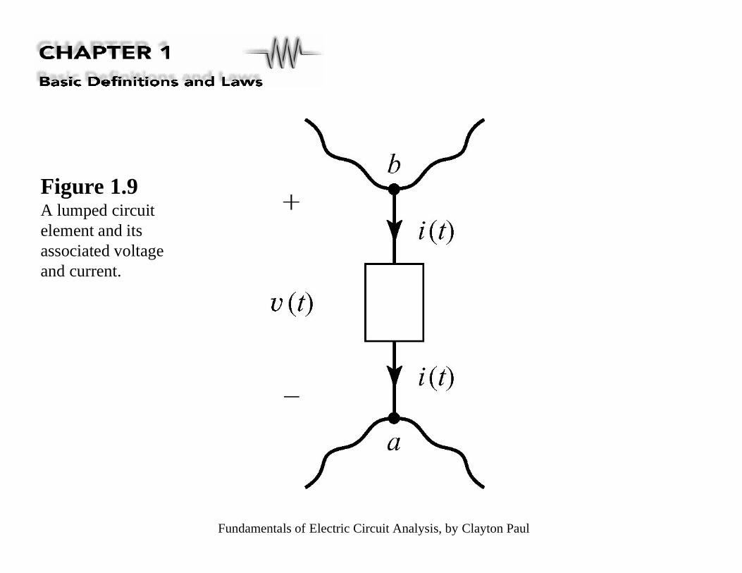
Figure 1.9A lumped circuitelement and itsassociated voltageand current.
Fundamentals of Electric Circuit Analysis, by Clayton Paul
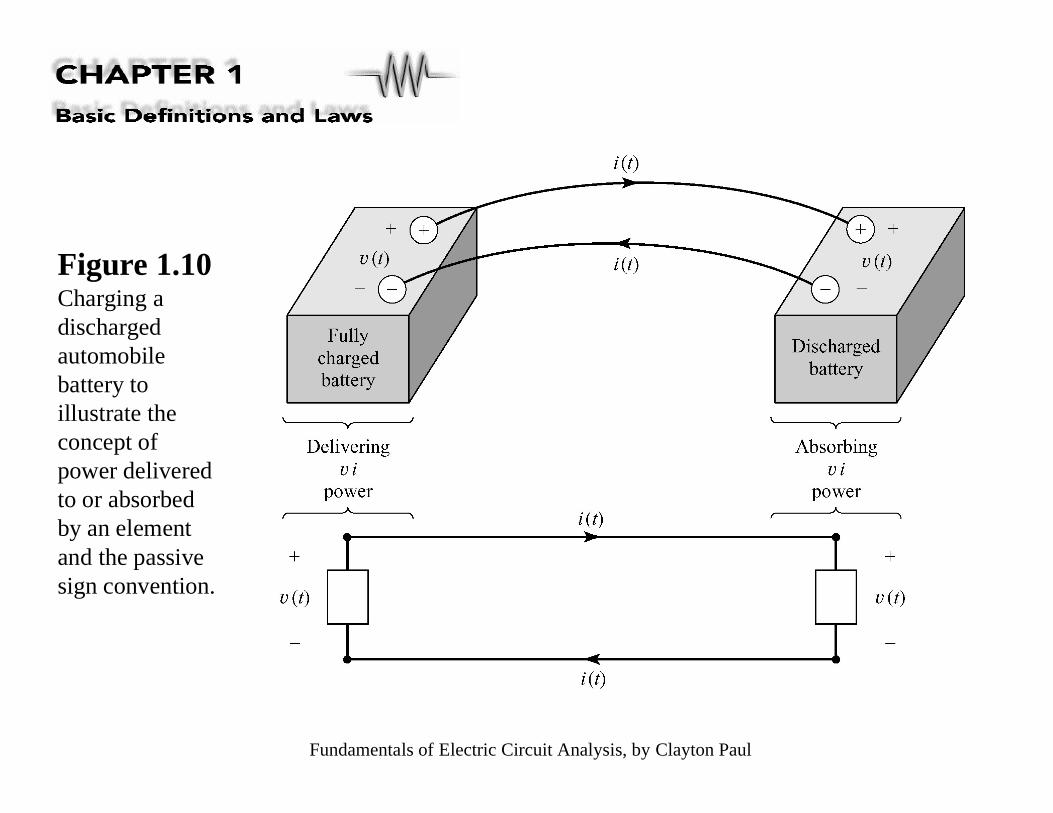
Figure 1.10Charging adischargedautomobilebattery toillustrate theconcept ofpower deliveredto or absorbedby an elementand the passivesign convention.

Fundamentals of Electric Circuit Analysis, by Clayton Paul
Figure 1.11 Illustration of the power delivered to (absorbed by) an element and thepower delivered by the element.
Fundamentals of Electric Circuit Analysis, by Clayton Paul
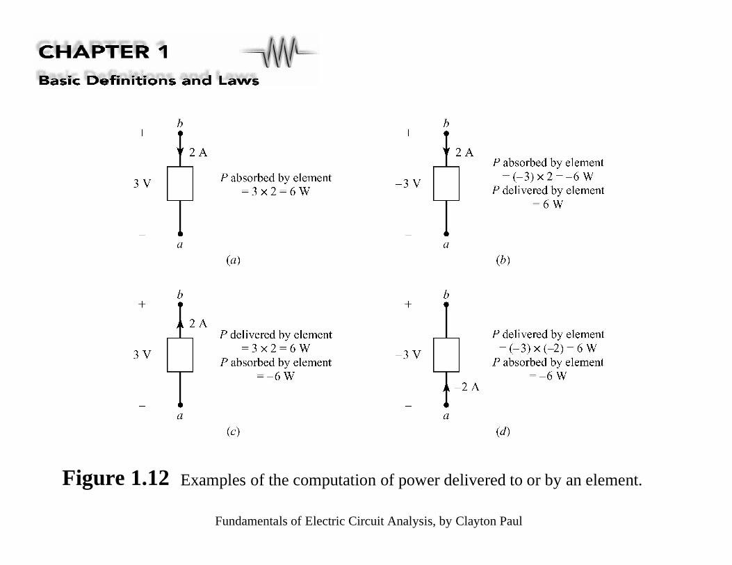
Figure 1.12 Examples of the computation of power delivered to or by an element.
Fundamentals of Electric Circuit Analysis, by Clayton Paul
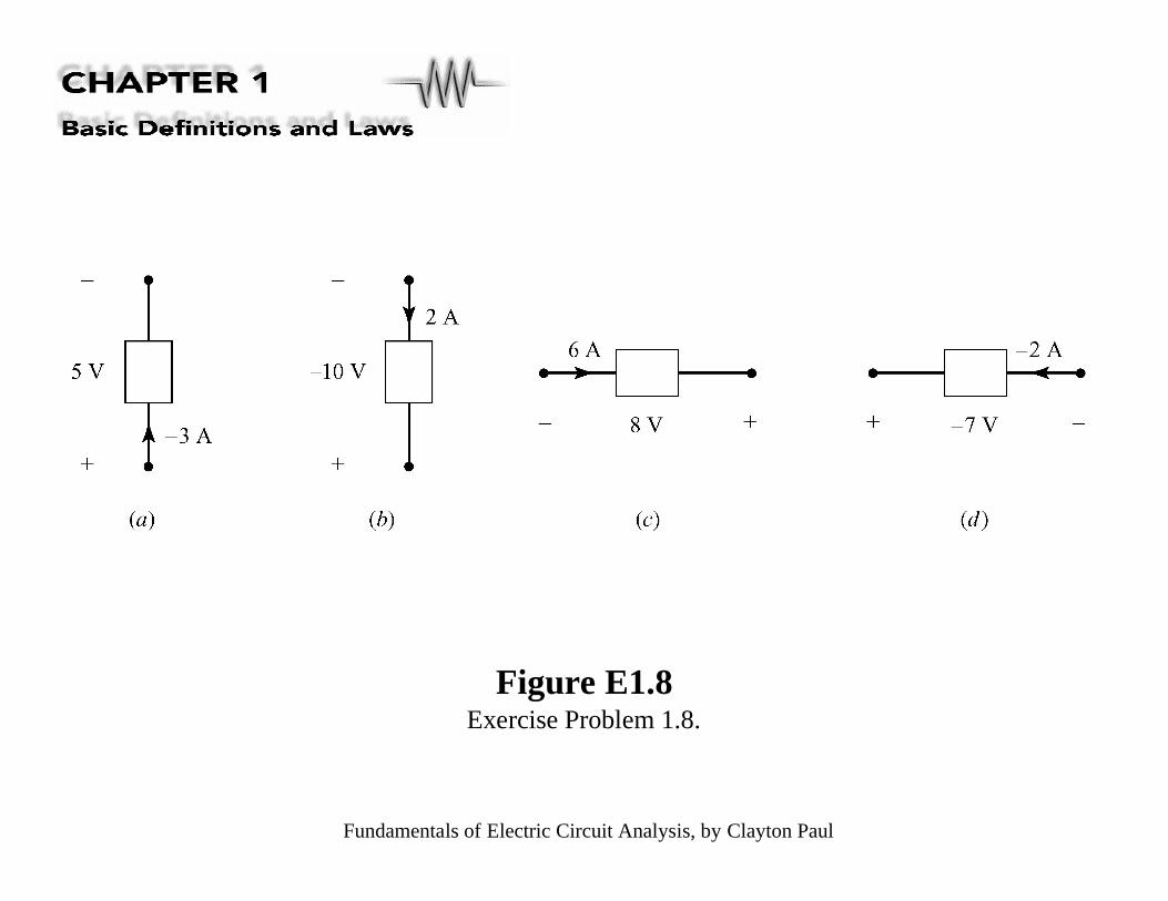
Figure E1.8Exercise Problem 1.8.

Fundamentals of Electric Circuit Analysis, by Clayton Paul
Figure 1.13Illustration of an electric circuit as a particular interconnection of circuit elements.

Fundamentals of Electric Circuit Analysis, by Clayton Paul
Figure 1.14 Illustration of Kirchhoff
’s current law (KCL).
Fundamentals of Electric Circuit Analysis, by Clayton Paul
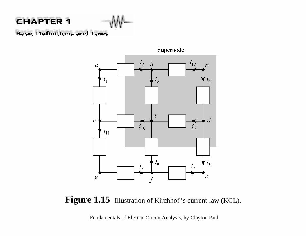
Figure 1.15 Illustration of Kirchhof
’s current law (KCL).

Fundamentals of Electric Circuit Analysis, by Clayton Paul
Figure 1.16Example 1.3.
Fundamentals of Electric Circuit Analysis, by Clayton Paul
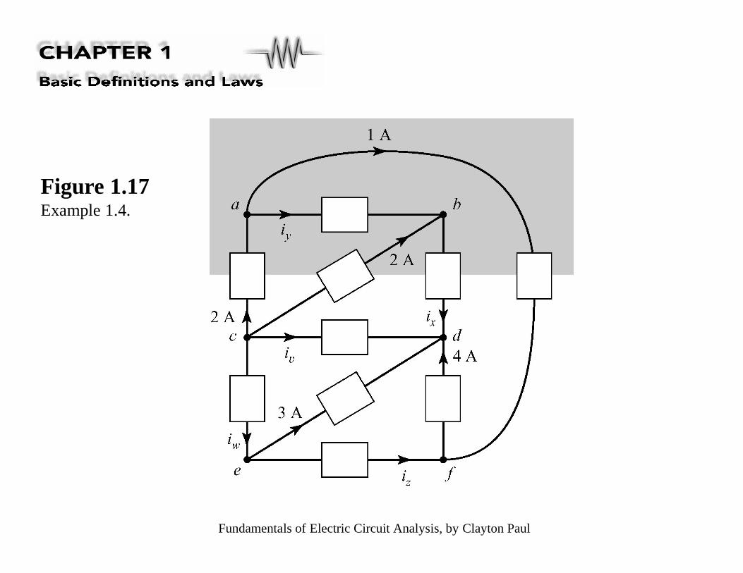
Figure 1.17Example 1.4.

Fundamentals of Electric Circuit Analysis, by Clayton Paul
Figure 1.18Example 1.5.

Fundamentals of Electric Circuit Analysis, by Clayton Paul
Figure E1.9Exercise Problem 1.9.
Fundamentals of Electric Circuit Analysis, by Clayton Paul
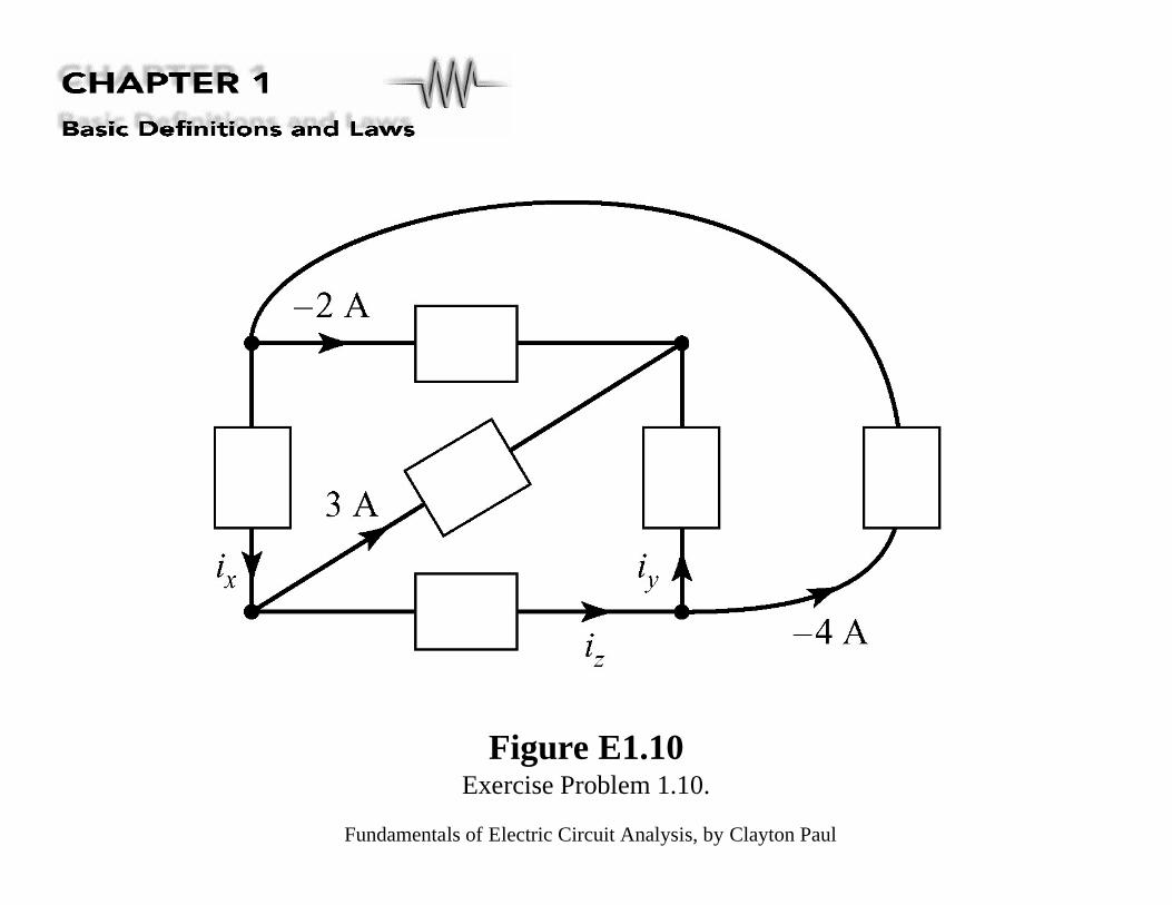
Figure E1.10Exercise Problem 1.10.

Fundamentals of Electric Circuit Analysis, by Clayton Paul
Figure E1.11Exercise Problem 1.11.
Fundamentals of Electric Circuit Analysis, by Clayton Paul
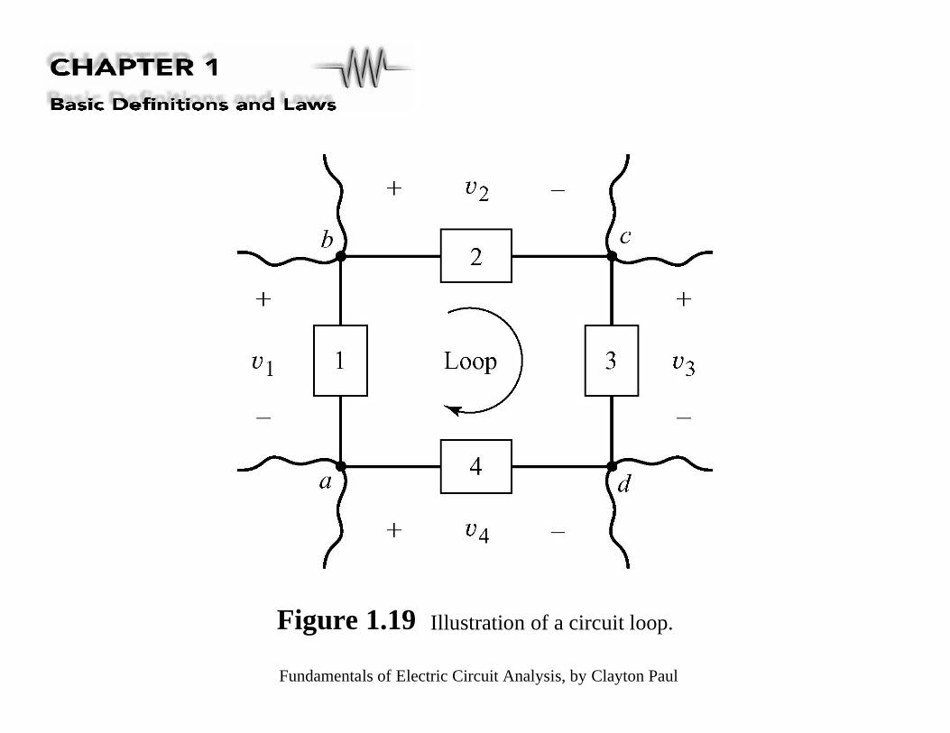
Figure 1.19 Illustration of a circuit loop.

Fundamentals of Electric Circuit Analysis, by Clayton Paul
Figure 1.20 Illustration of the concepts of (a) voltage rise and (b) voltage drop.

Fundamentals of Electric Circuit Analysis, by Clayton Paul
Figure 1.21Illustration of amethod for correctlywriting KVL withreference to thecircuit of Fig. 1.19.
Fundamentals of Electric Circuit Analysis, by Clayton Paul
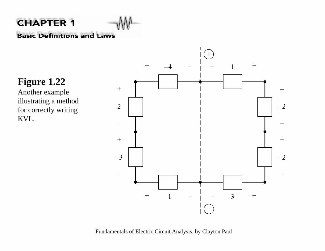
Figure 1.22Another exampleillustrating a methodfor correctly writingKVL.

Fundamentals of Electric Circuit Analysis, by Clayton Paul
Figure 1.23 Another example of the application of KVL.
Fundamentals of Electric Circuit Analysis, by Clayton Paul
Figure 1.24The seven loops in thecircuit of Fig. 1.23, withKVL written for each.
Fundamentals of Electric Circuit Analysis, by Clayton Paul
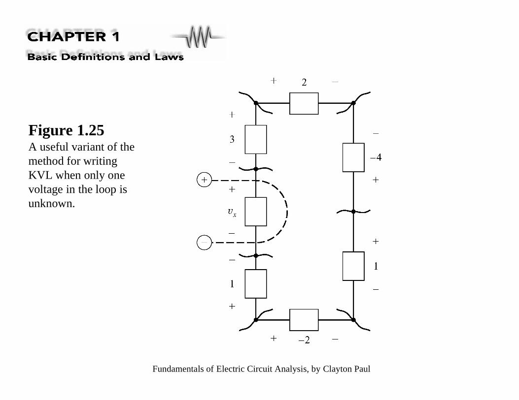
Figure 1.25A useful variant of themethod for writingKVL when only onevoltage in the loop isunknown.

Fundamentals of Electric Circuit Analysis, by Clayton Paul
Figure 1.26Another illustrationof writing KVL for aloop where only onevoltage is unknown.

Fundamentals of Electric Circuit Analysis, by Clayton Paul
Figure 1.27Illustration thatKVL is a result ofthe law ofconservation ofenergy.
Fundamentals of Electric Circuit Analysis, by Clayton Paul
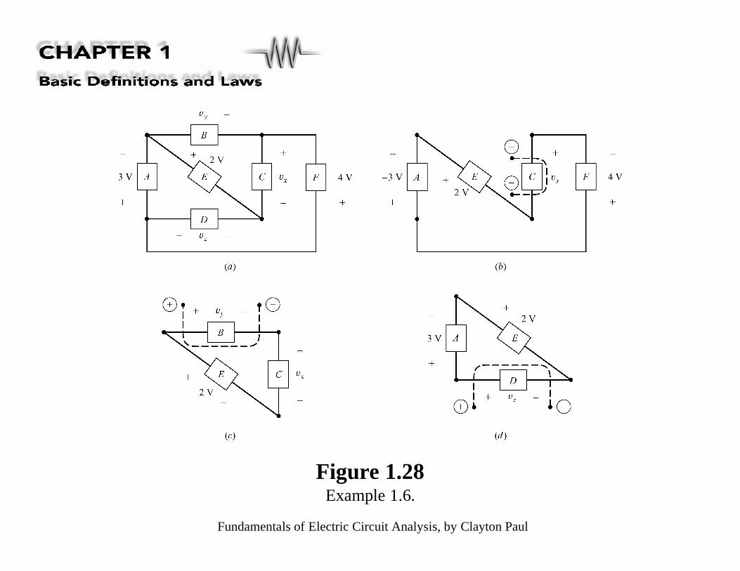
Figure 1.28Example 1.6.

Fundamentals of Electric Circuit Analysis, by Clayton Paul
Figure 1.29Example 1.7.
Fundamentals of Electric Circuit Analysis, by Clayton Paul
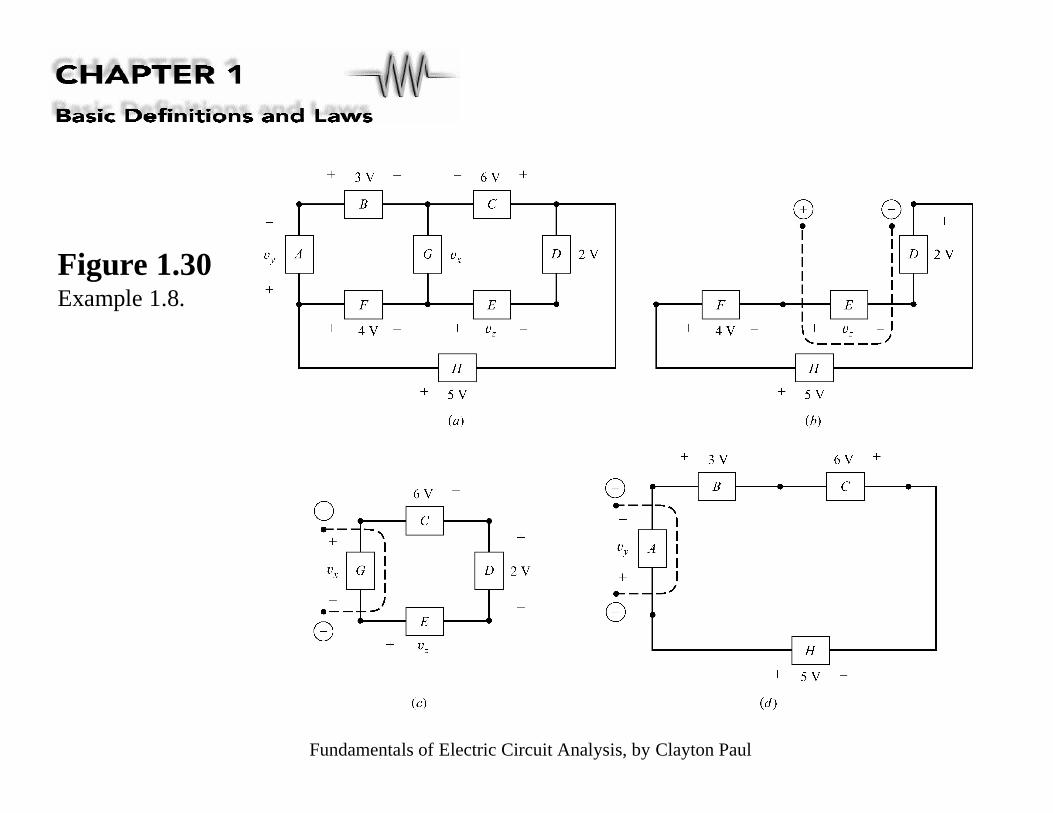
Figure 1.30Example 1.8.
Fundamentals of Electric Circuit Analysis, by Clayton Paul
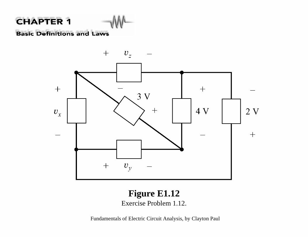
Figure E1.12Exercise Problem 1.12.

Fundamentals of Electric Circuit Analysis, by Clayton Paul
Figure E1.13Exercise Problem 1.13.

Fundamentals of Electric Circuit Analysis, by Clayton Paul
Figure E1.14Exercise Problem 1.14.

Fundamentals of Electric Circuit Analysis, by Clayton Paul
Figure 1.31Example 1.9.
Fundamentals of Electric Circuit Analysis, by Clayton Paul
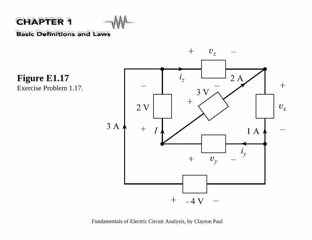
Figure E1.17Exercise Problem 1.17.

Fundamentals of Electric Circuit Analysis, by Clayton Paul
Figure E1.18Exercise Problem 1.18.

Fundamentals of Electric Circuit Analysis, by Clayton Paul
Figure 1.32Illustration of(a) the seriesconnection ofelements, and(b) the parallelconnection ofelements.

Fundamentals of Electric Circuit Analysis, by Clayton Paul
Figure 1.33Examples to illustrateto proper classificationof series and parallelconnections.
Fundamentals of Electric Circuit Analysis, by Clayton Paul
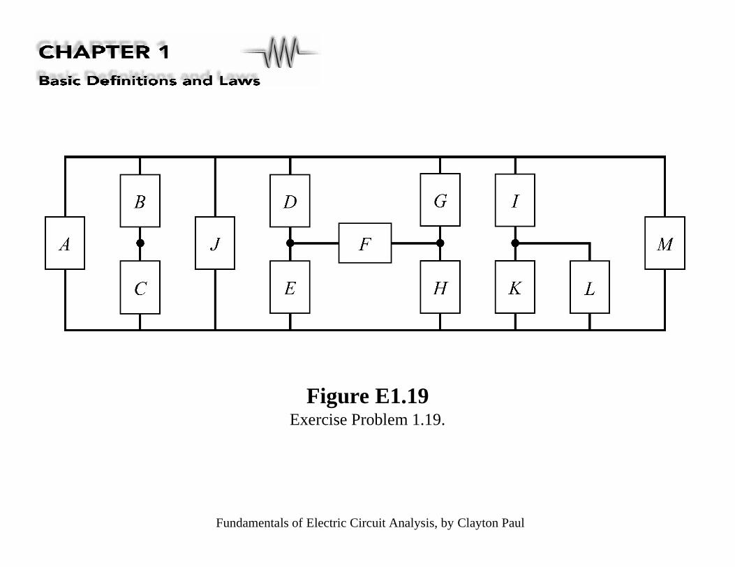
Figure E1.19Exercise Problem 1.19.
Fundamentals of Electric Circuit Analysis, by Clayton Paul
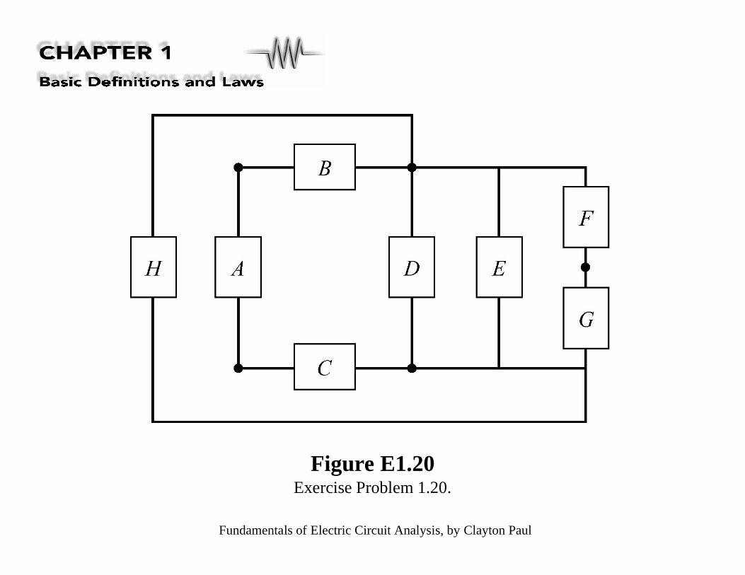
Figure E1.20Exercise Problem 1.20.
Fundamentals of Electric Circuit Analysis, by Clayton Paul
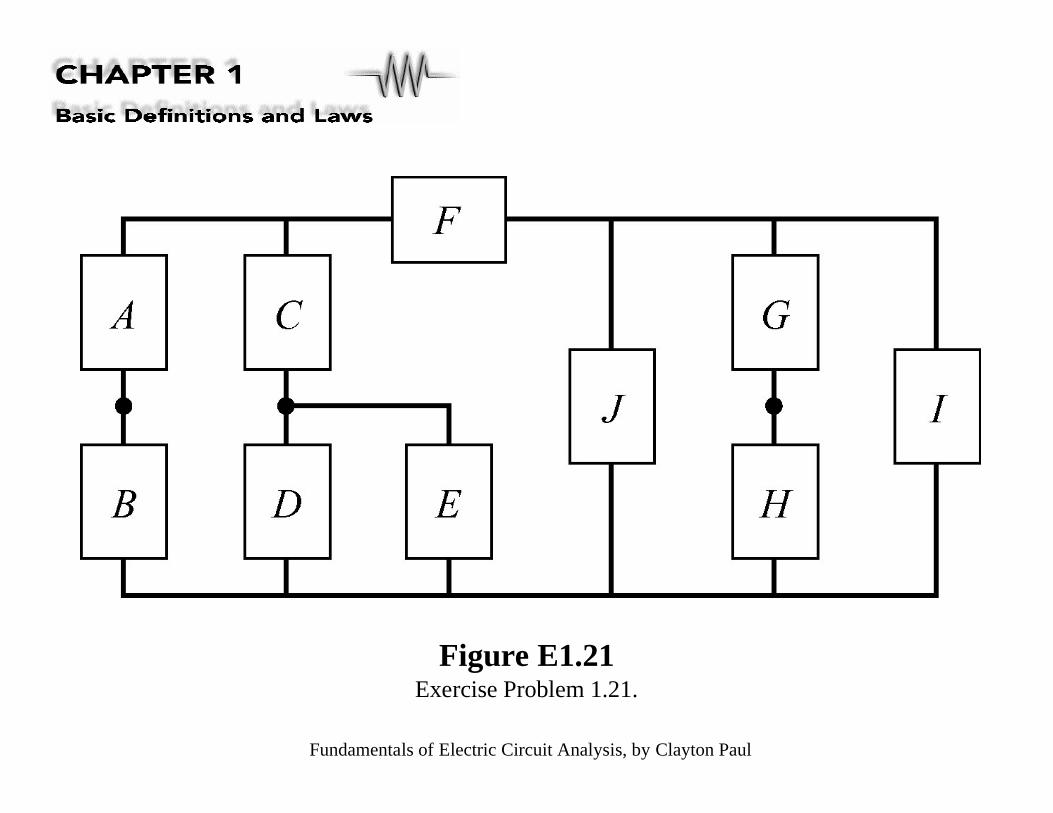
Figure E1.21Exercise Problem 1.21.

Fundamentals of Electric Circuit Analysis, by Clayton Paul
Figure 1.34Illustration of the concept of equivalent circuits.
Fundamentals of Electric Circuit Analysis, by Clayton Paul
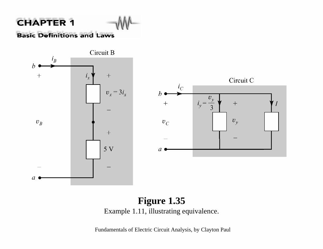
Figure 1.35Example 1.11, illustrating equivalence.
Fundamentals of Electric Circuit Analysis, by Clayton Paul
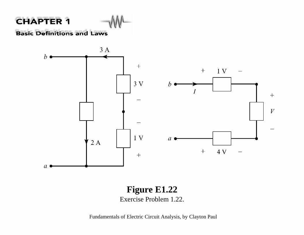
Figure E1.22Exercise Problem 1.22.
Fundamentals of Electric Circuit Analysis, by Clayton Paul
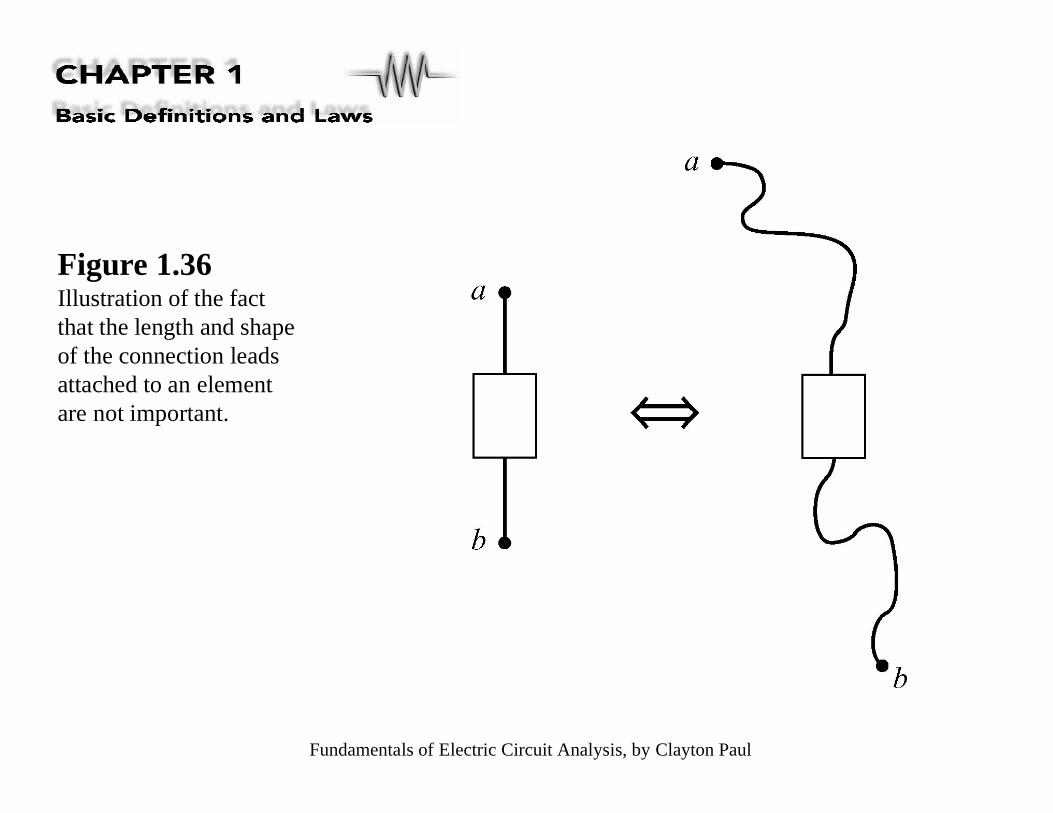
Figure 1.36Illustration of the factthat the length and shapeof the connection leadsattached to an elementare not important.
Fundamentals of Electric Circuit Analysis, by Clayton Paul
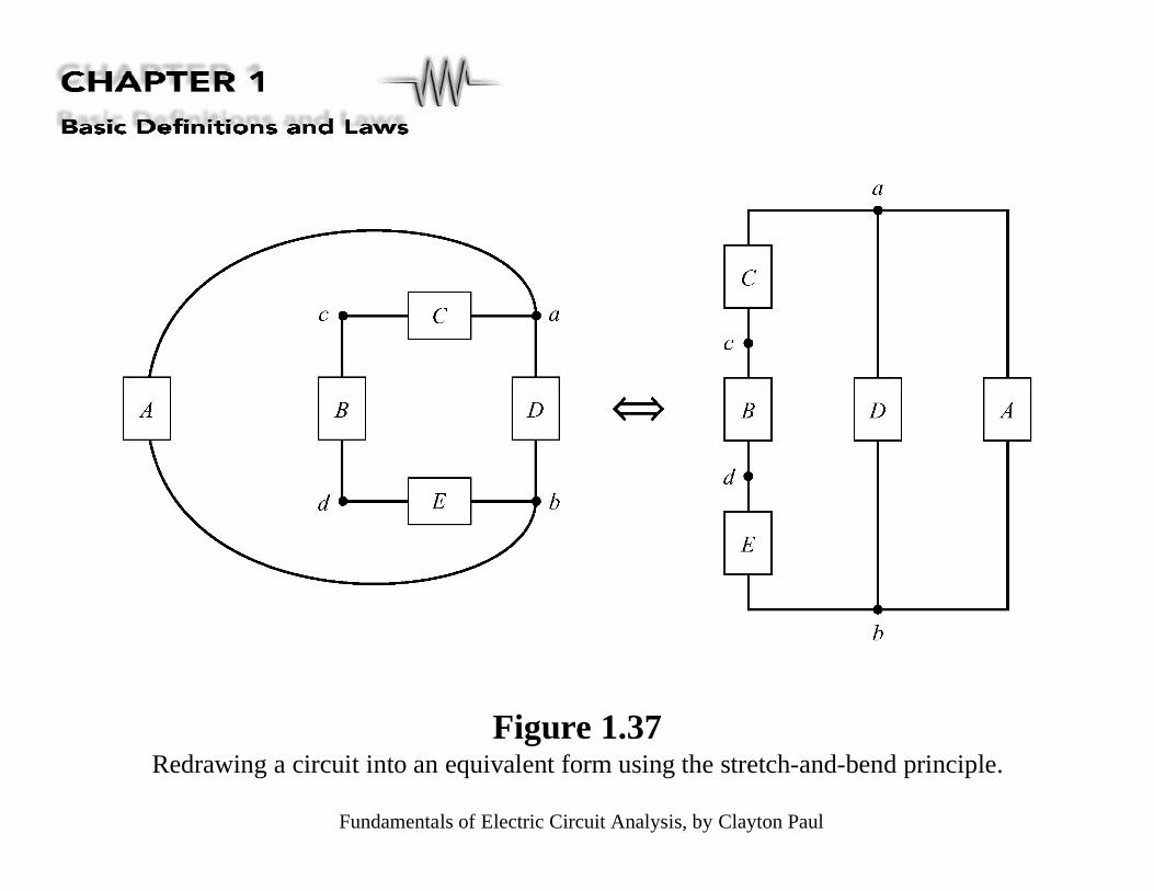
Figure 1.37Redrawing a circuit into an equivalent form using the stretch-and-bend principle.
Fundamentals of Electric Circuit Analysis, by Clayton Paul
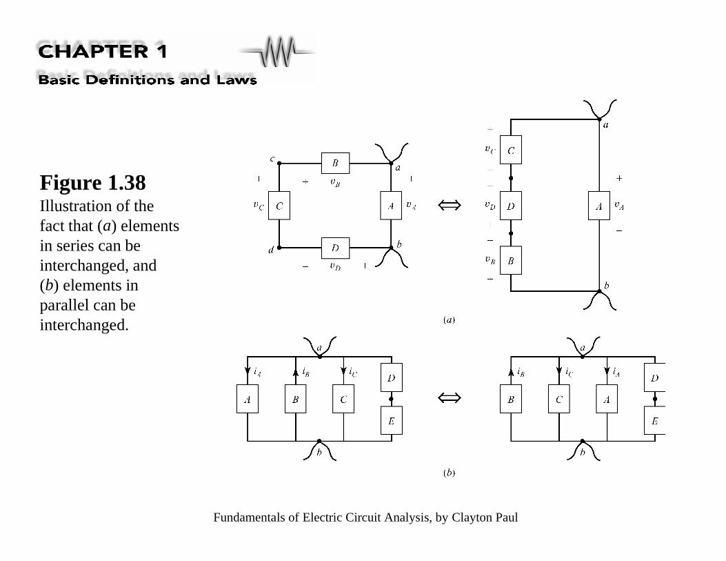
Figure 1.38Illustration of thefact that (a) elementsin series can beinterchanged, and(b) elements inparallel can beinterchanged.

Fundamentals of Electric Circuit Analysis, by Clayton Paul
Figure 1.39 An element’s connection point may be moved along a connection lead.Observe that there are only three nodes in this circuit.

Fundamentals of Electric Circuit Analysis, by Clayton Paul
Figure 1.40Illustration of commonerrors in redrawing acircuit: (a) cutting aconnection lead andmoving it to anothernode, and (b) cuttingthe connection leads ofan element andinserting the element inanother place.

Fundamentals of Electric Circuit Analysis, by Clayton Paul
Figure 1.41(Continued)
Fundamentals of Electric Circuit Analysis, by Clayton Paul
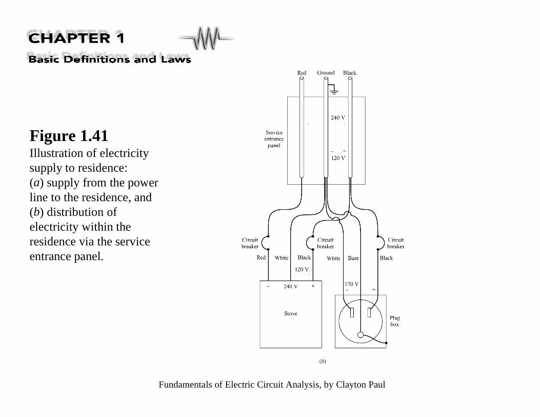
Figure 1.41Illustration of electricitysupply to residence:(a) supply from the powerline to the residence, and(b) distribution ofelectricity within theresidence via the serviceentrance panel.
Fundamentals of Electric Circuit Analysis, by Clayton Paul
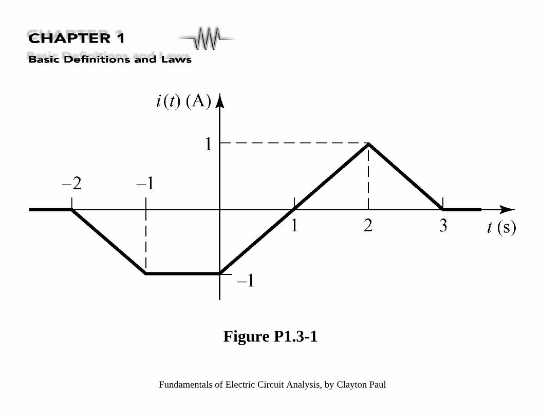
Figure P1.3-1
Fundamentals of Electric Circuit Analysis, by Clayton Paul
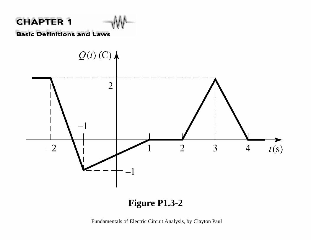
Figure P1.3-2
Fundamentals of Electric Circuit Analysis, by Clayton Paul
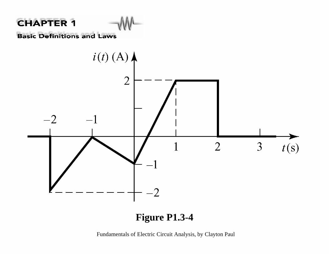
Figure P1.3-4

Fundamentals of Electric Circuit Analysis, by Clayton Paul
Figure P1.3-5
Fundamentals of Electric Circuit Analysis, by Clayton Paul
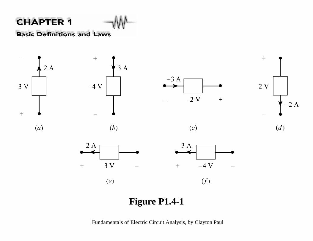
Figure P1.4-1
Fundamentals of Electric Circuit Analysis, by Clayton Paul
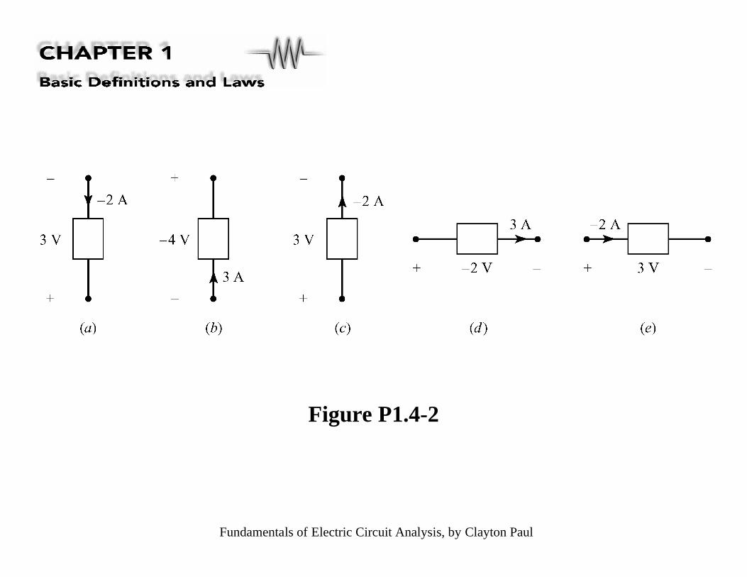
Figure P1.4-2
Fundamentals of Electric Circuit Analysis, by Clayton Paul
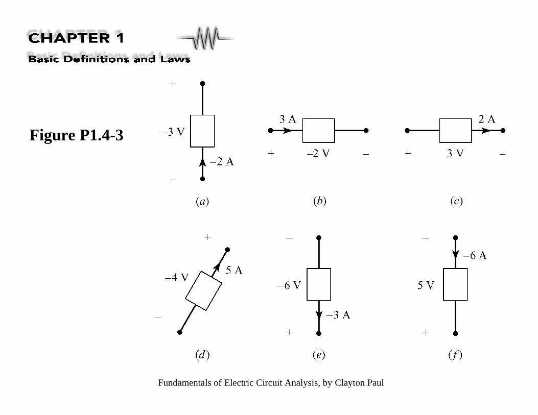
Figure P1.4-3

Fundamentals of Electric Circuit Analysis, by Clayton Paul
Figure P1.4-4
Fundamentals of Electric Circuit Analysis, by Clayton Paul
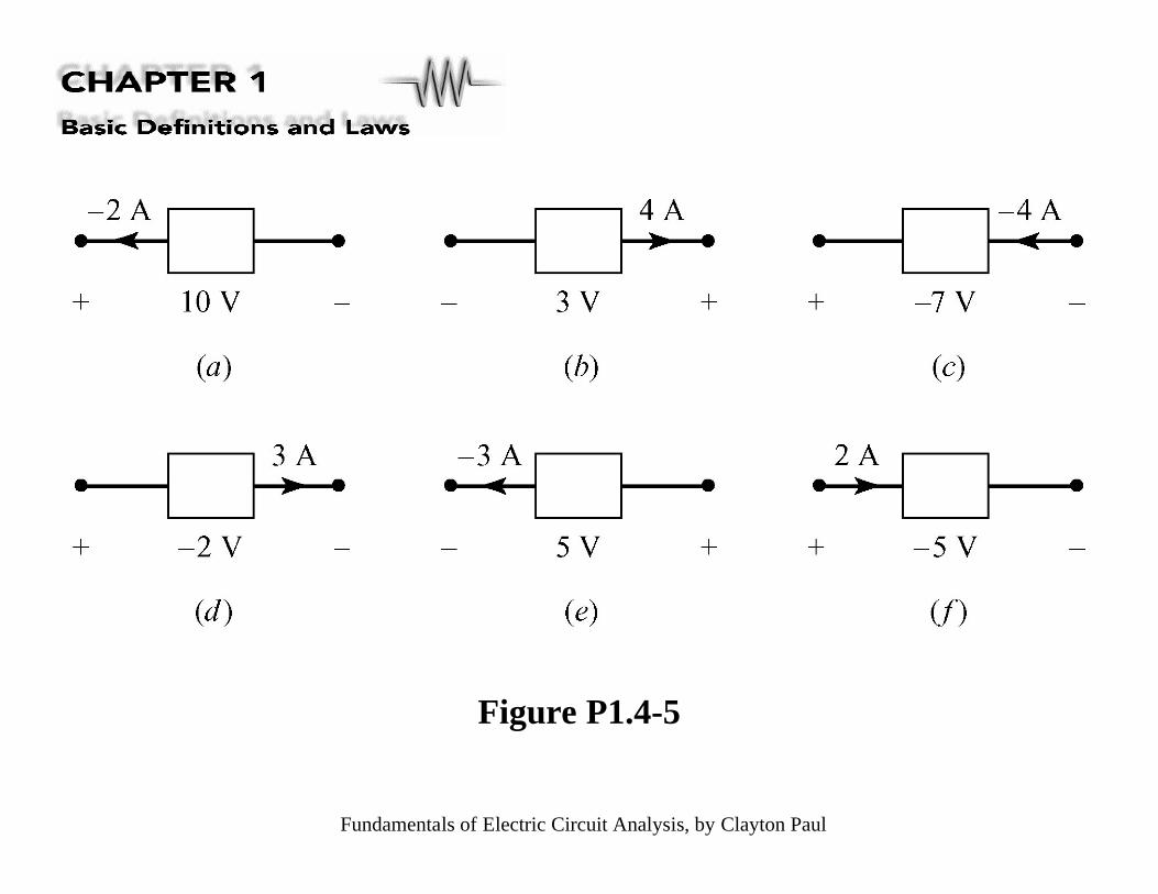
Figure P1.4-5

Fundamentals of Electric Circuit Analysis, by Clayton Paul
Figure P1.5-1
Fundamentals of Electric Circuit Analysis, by Clayton Paul
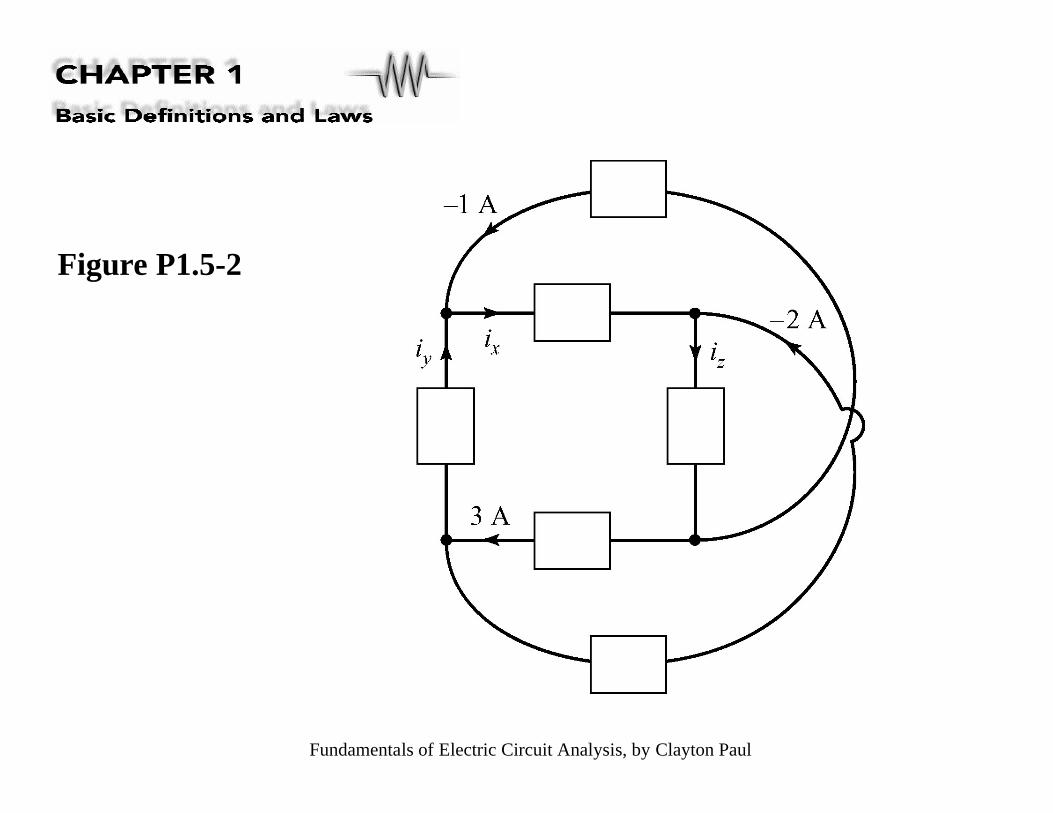
Figure P1.5-2

Fundamentals of Electric Circuit Analysis, by Clayton Paul
Figure P1.5-3

Fundamentals of Electric Circuit Analysis, by Clayton Paul
Figure P1.5-4

Fundamentals of Electric Circuit Analysis, by Clayton Paul
Figure P1.5-5
Fundamentals of Electric Circuit Analysis, by Clayton Paul
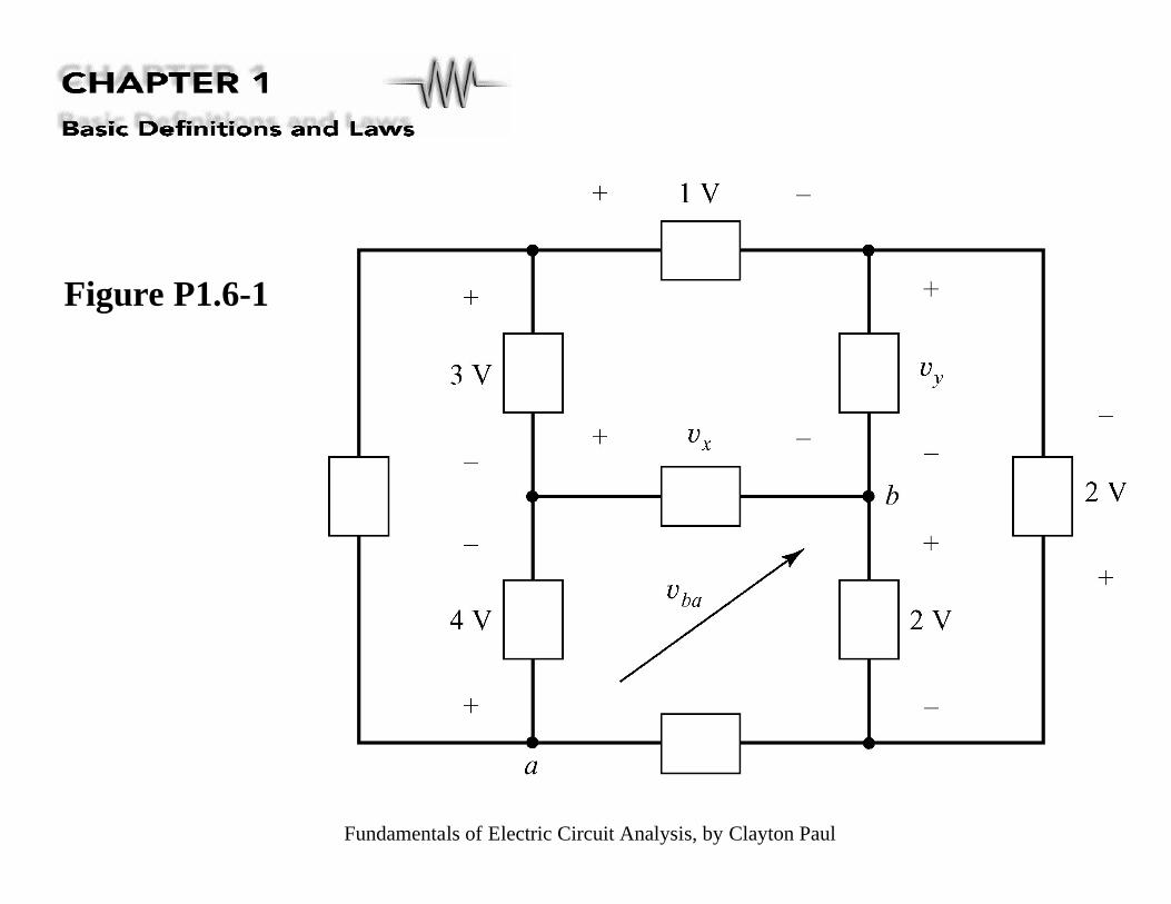
Figure P1.6-1
Fundamentals of Electric Circuit Analysis, by Clayton Paul
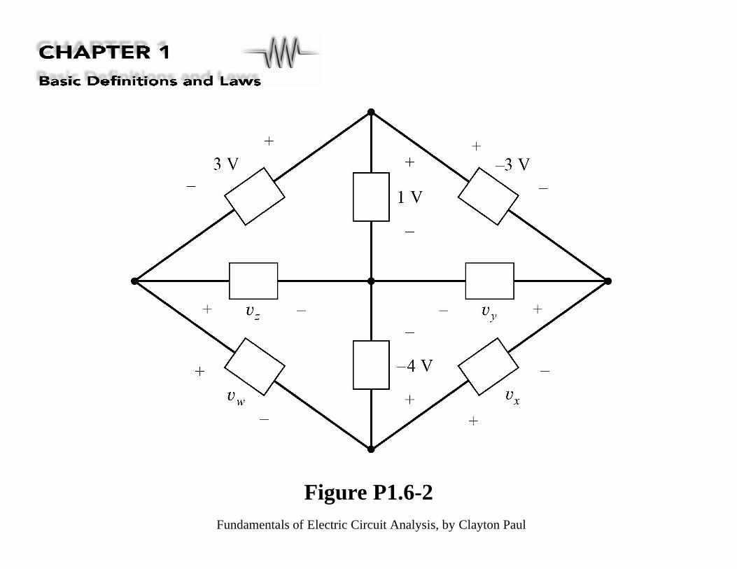
Figure P1.6-2

Fundamentals of Electric Circuit Analysis, by Clayton Paul
Figure P1.6-3

Fundamentals of Electric Circuit Analysis, by Clayton Paul
Figure P1.6-4

Fundamentals of Electric Circuit Analysis, by Clayton Paul
Figure P1.6-5

Fundamentals of Electric Circuit Analysis, by Clayton Paul
Figure P1.6-6
Fundamentals of Electric Circuit Analysis, by Clayton Paul
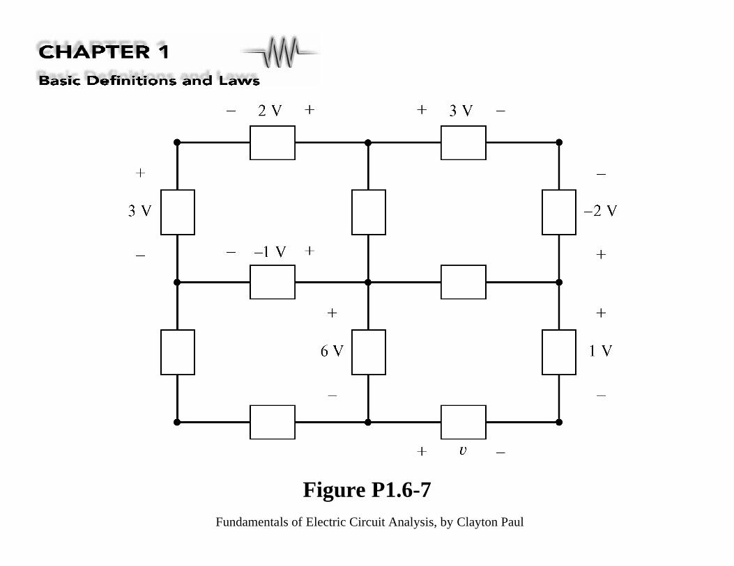
Figure P1.6-7

Fundamentals of Electric Circuit Analysis, by Clayton Paul
Figure P1.7-1
Fundamentals of Electric Circuit Analysis, by Clayton Paul
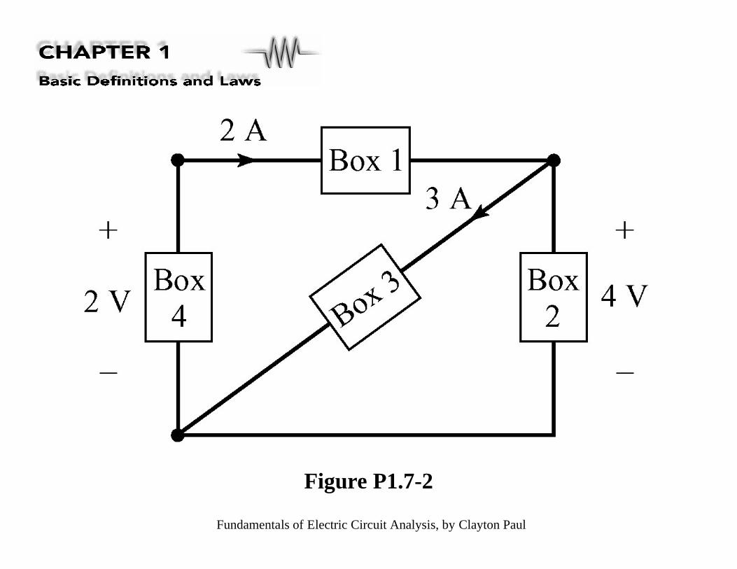
Figure P1.7-2

Fundamentals of Electric Circuit Analysis, by Clayton Paul
Figure P1.7-3

Fundamentals of Electric Circuit Analysis, by Clayton Paul
Figure P1.7-4

Fundamentals of Electric Circuit Analysis, by Clayton Paul
Figure P1.8-1

Fundamentals of Electric Circuit Analysis, by Clayton Paul
Figure P1.8-2
Fundamentals of Electric Circuit Analysis, by Clayton Paul
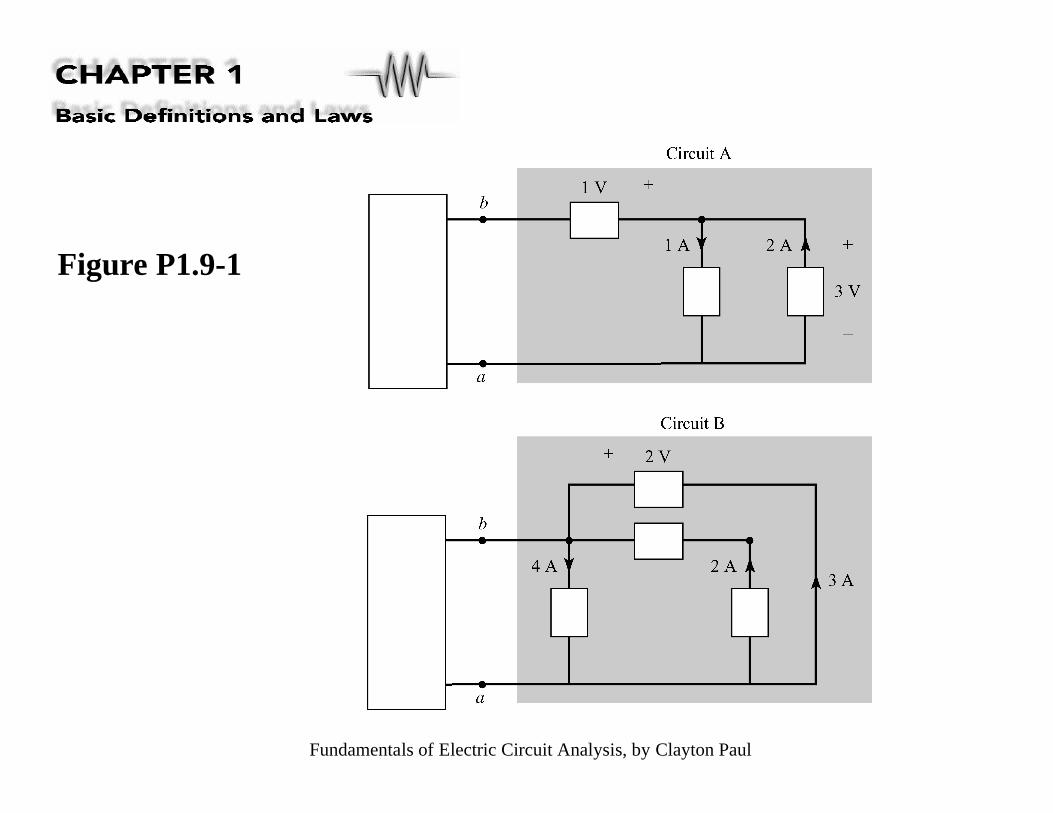
Figure P1.9-1