field welding · qualification to ansi/aws d1.1 structural welding code is not acceptable. (refer...
TRANSCRIPT
INSPECTION OF
FIELD WELDING
Objective
Types of Projects Involving Welding Common Welding Terms & Symbols Welder Qualifications Common Welding Requirements Welding Inspection
Types of Projects Involving Field Welding
New Structures: • Bridge Rail • Strip Seal Extrusions / Armor Angles • Pile-to-Girder Connections • Pile splice
Types of Projects Involving Field Welding
Rehabilitation Projects • Bridge Rail • Strip Seal Extrusions / Armor Angles • Fatigue Retrofits • Weld Repairs
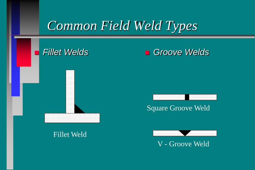
Common Field Weld Types
Fillet Welds
Groove Welds
Fillet Weld
Square Groove Weld
V - Groove Weld
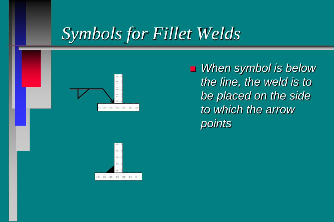
Symbols for Fillet Welds
When symbol is below the line, the weld is to be placed on the side to which the arrow points
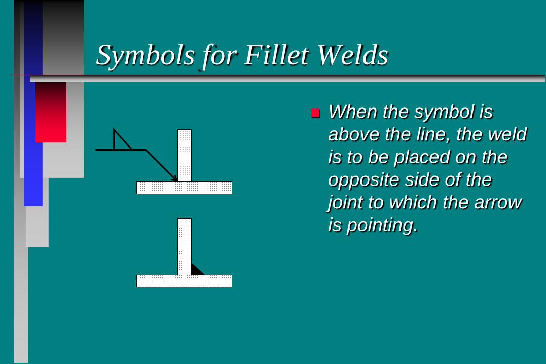
Symbols for Fillet Welds
When the symbol is above the line, the weld is to be placed on the opposite side of the joint to which the arrow is pointing.
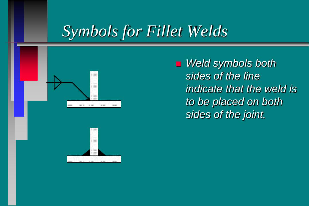
Symbols for Fillet Welds
Weld symbols both sides of the line indicate that the weld is to be placed on both sides of the joint.
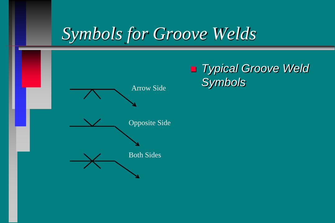
Symbols for Groove Welds
Typical Groove Weld Symbols Arrow Side
Opposite Side
Both Sides

Additional Weld Markings
Field Weld
Weld All Around
Tail on end of weld is where any special instruction are placed
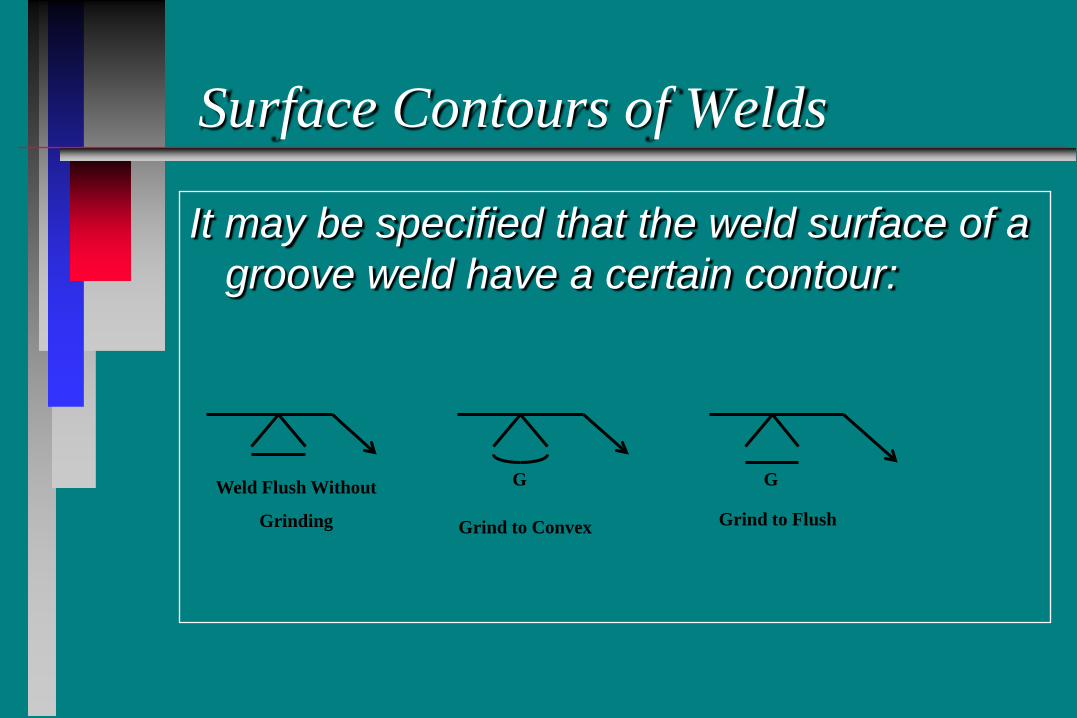
Surface Contours of Welds
It may be specified that the weld surface of a groove weld have a certain contour:
G G Weld Flush Without
Grinding Grind to Convex Grind to Flush
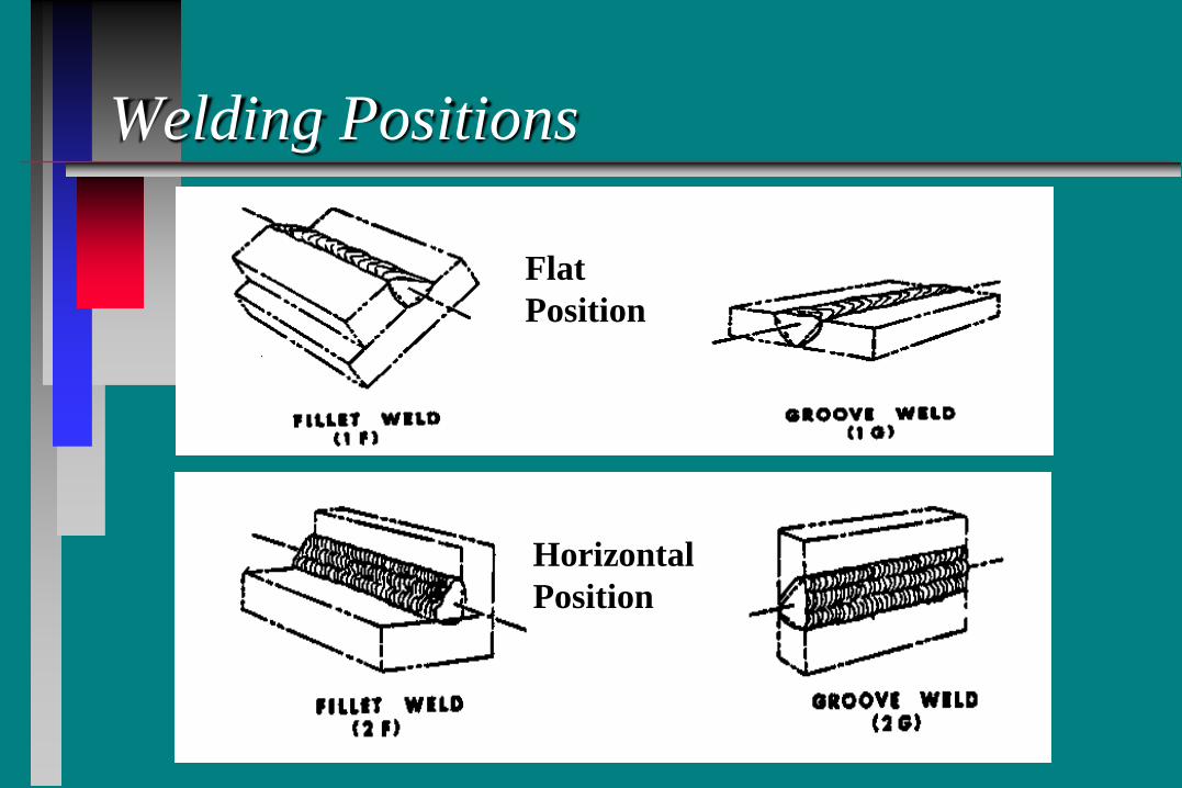
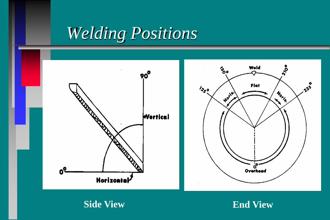
Welding Positions
Flat Position
Horizontal Position
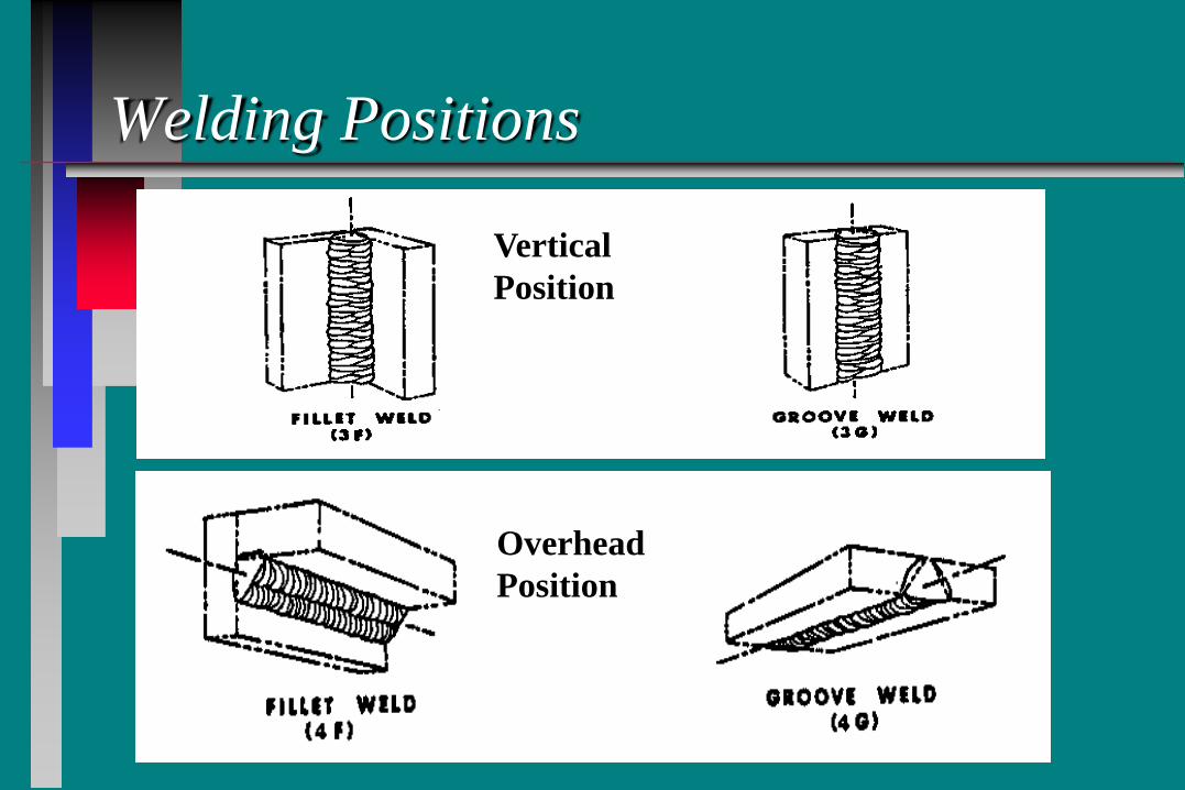
Welding Positions
Vertical Position
Overhead Position
Welding Positions
Side View
Side View End View
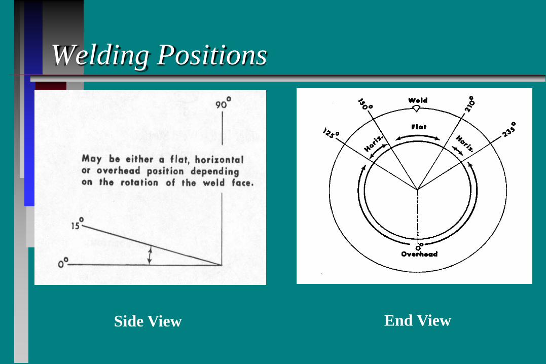
Welding Positions
Side View End View
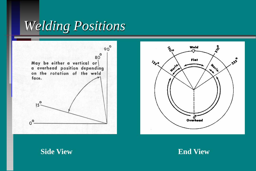
Welding Positions
Side View End View
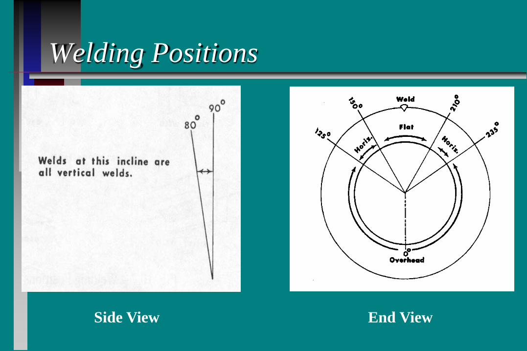
Welding Positions
Side View End View
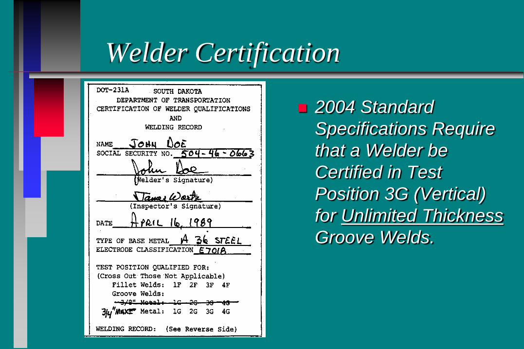
Welder Certification
2004 Standard Specifications Require that a Welder be Certified in Test Position 3G (Vertical) for Unlimited Thickness Groove Welds.
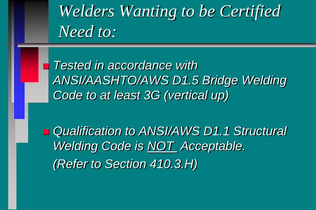
Welders Wanting to be Certified Need to:
Tested in accordance with ANSI/AASHTO/AWS D1.5 Bridge Welding Code to at least 3G (vertical up)
Qualification to ANSI/AWS D1.1 Structural Welding Code is NOT Acceptable.
(Refer to Section 410.3.H)
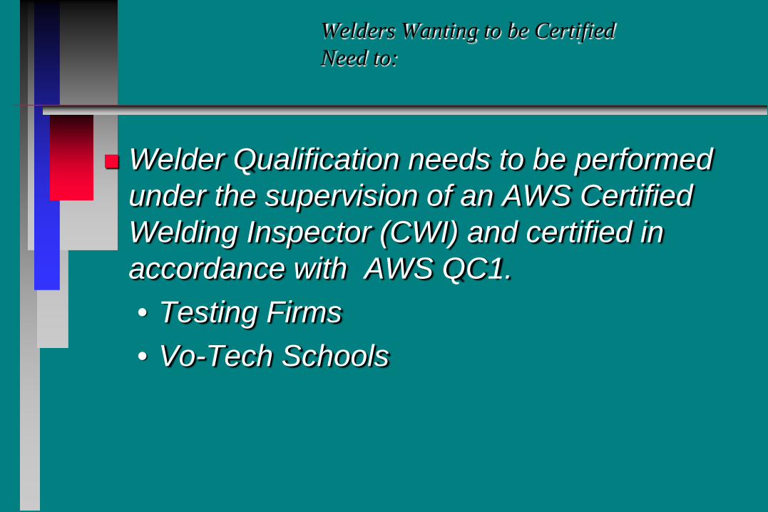
Welders Wanting to be Certified Need to:
Welder Qualification needs to be performed under the supervision of an AWS Certified Welding Inspector (CWI) and certified in accordance with AWS QC1. • Testing Firms • Vo-Tech Schools
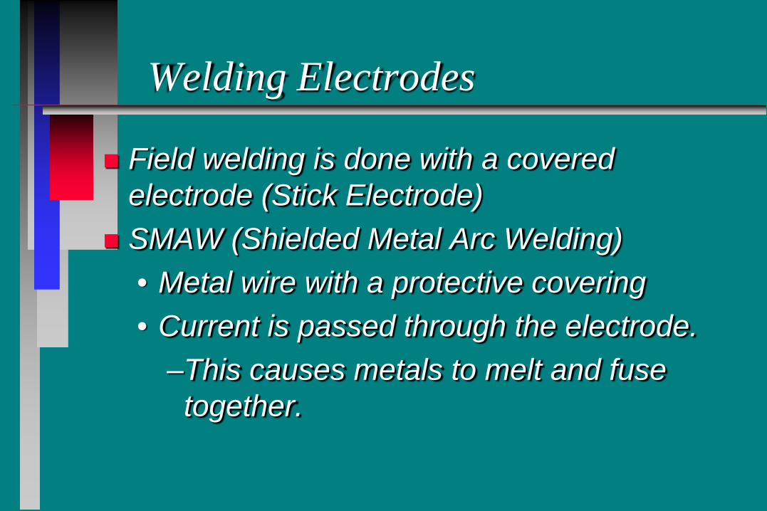
Welding Electrodes
Field welding is done with a covered electrode (Stick Electrode)
SMAW (Shielded Metal Arc Welding) • Metal wire with a protective covering • Current is passed through the electrode.
–This causes metals to melt and fuse together.
Welding Electrodes
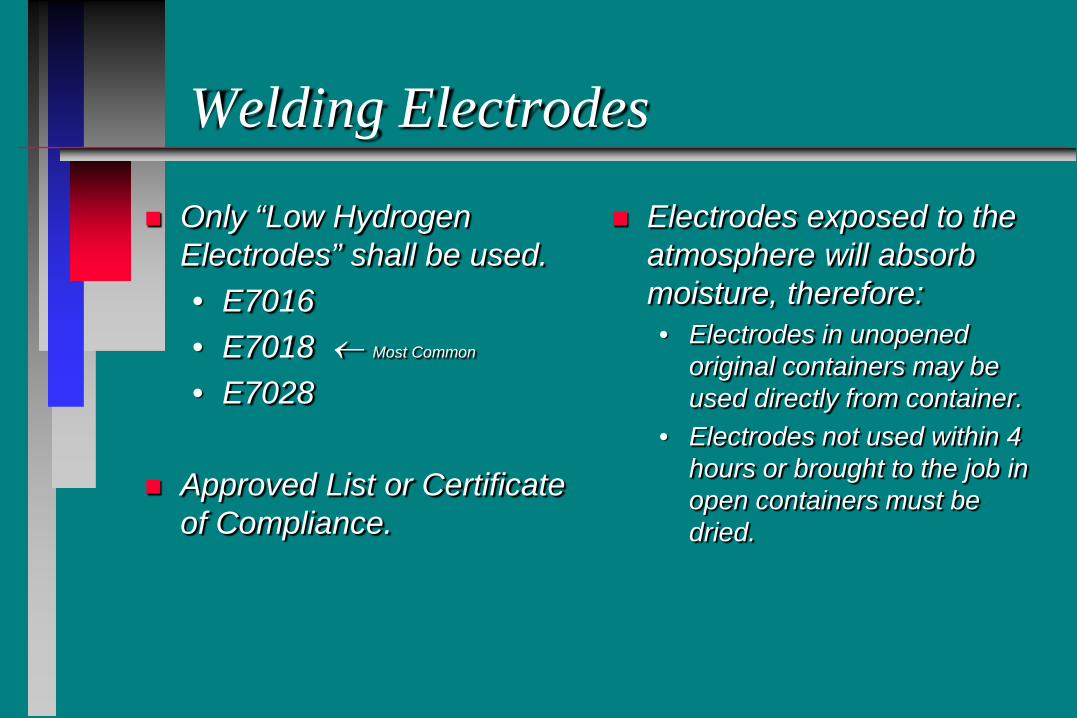
Only “Low Hydrogen Electrodes” shall be used. • E7016 • E7018 ← Most Common
• E7028
Approved List or Certificate of Compliance.
Electrodes exposed to the atmosphere will absorb moisture, therefore: • Electrodes in unopened
original containers may be used directly from container.
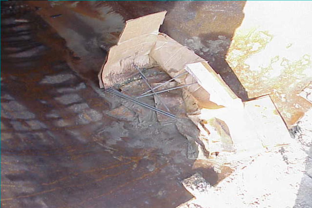
• Electrodes not used within 4 hours or brought to the job in open containers must be dried.
Drying Electrodes
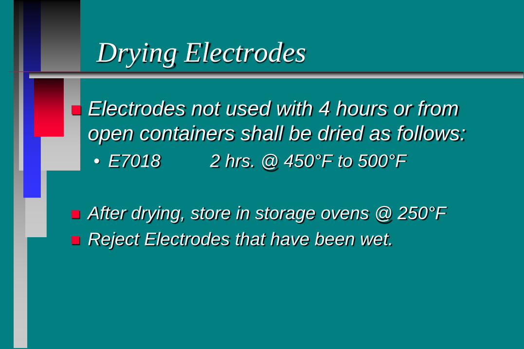
Electrodes not used with 4 hours or from open containers shall be dried as follows: • E7018 2 hrs. @ 450°F to 500°F
After drying, store in storage ovens @ 250°F Reject Electrodes that have been wet.
Weather and Temperature
• Steel Must be preheated • Welds shall not be placed when
there is rain rain or snow • Preheat will remove any water
on cold days
Preheat
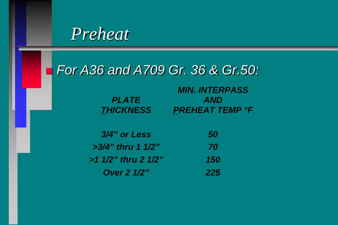
For A36 and A709 Gr. 36 & Gr.50:
PLATETHICKNESS
MIN. INTERPASSAND
PREHEAT TEMP °F
3/4” or Less 50>3/4” thru 1 1/2” 70
>1 1/2” thru 2 1/2” 150Over 2 1/2” 225
Preheat
Carefully Review Plans/Shop Plans for Other Preheat Conditions. • Other Types of Steels May Require Higher
Preheat. • High Restraint Details May Require Higher
Preheat.
Preheat
Methods of Monitoring Preheat • Surface Thermometer • Thermomelt Stick
– Thermomelt Sticks are made for several different temperatures.
– Make sure proper stick is used.
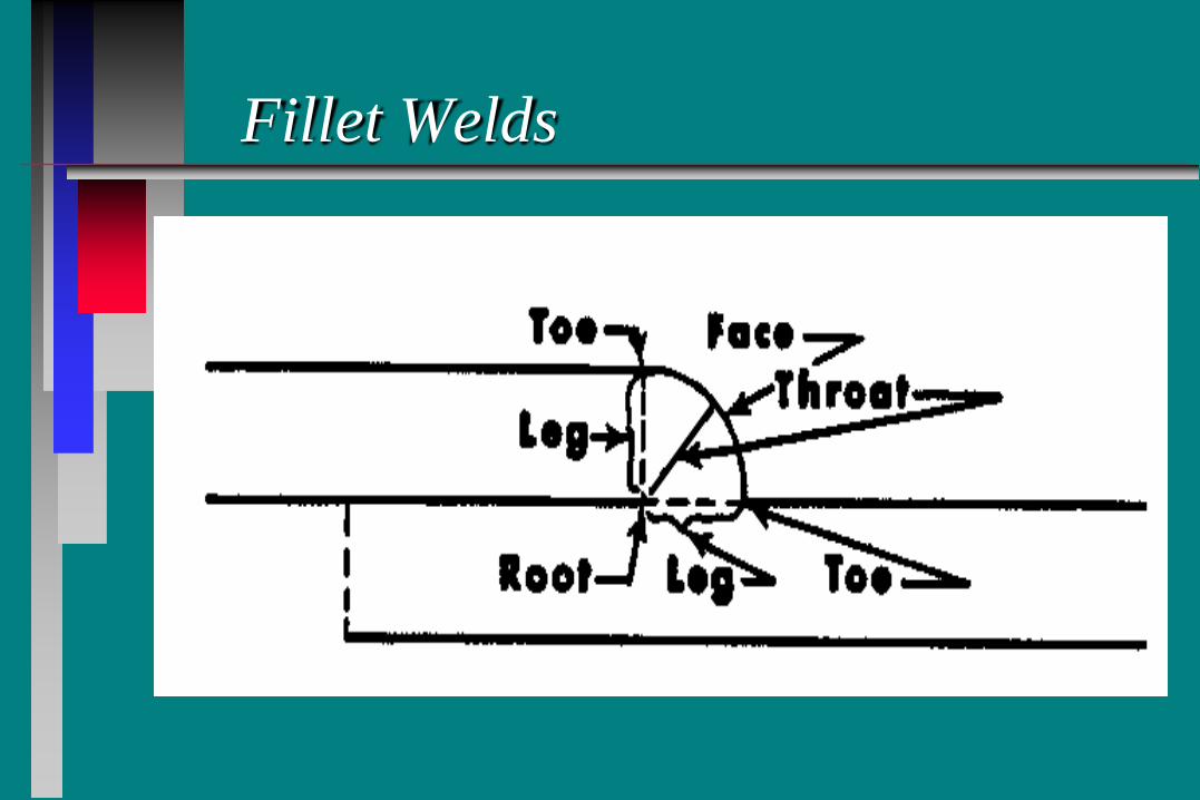
Fillet Welds
Preparation of Base Metal
Weld Connection Area Must be Free of Defects and be Cleaned 2” Each Side
of Weld: • No loose mill scale, rust, oil, or grease • Galvanizing / Paint Removed • Moisture Free

Fit-Up of Plates With Fillet Welds
Proper Fit-up and Weld Size • Plate separations of 1/16” to 3/16” require
leg of weld to be increased by the amount of seperation.
Fit-Up of Plates With Fillet Welds
Separations of More than 3/16” Should Not be Allowed. • Contractor must correct

Alignment of Plates
Plates Welded With Fillet or Groove Welds Need to be Held in Proper Alignment.
• Erection Bolts • Tack Welds • Clamps, Jacks, etc.
General Field Welding Procedures
Use Flat Welding Position if Possible Vertical Welds from Bottom Up Remove Slag Between Passes
• Chipping Hammer • Wire Brush
Arc Must be Struck in Immediate Weld Area
Inspection of Field Welds
Most Field Welding is in Low Stress Areas. • Visual Inspection
Welds in High Stress Areas are Much More Critical: • Visual Inspection • Non-Destructive Testing
Visual Inspection
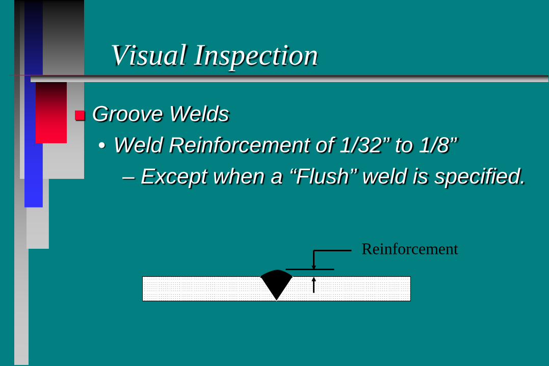
Groove Welds • Weld Reinforcement of 1/32” to 1/8”
– Except when a “Flush” weld is specified.
Reinforcement
Visual Inspection
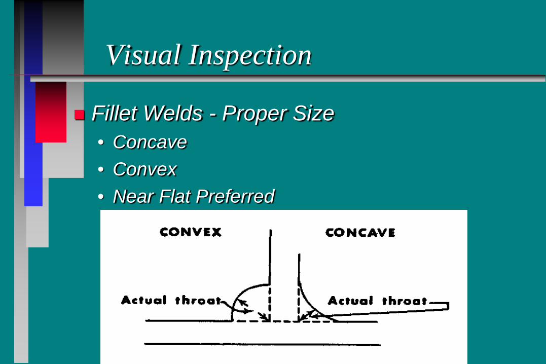
Fillet Welds - Proper Size • Concave • Convex • Near Flat Preferred
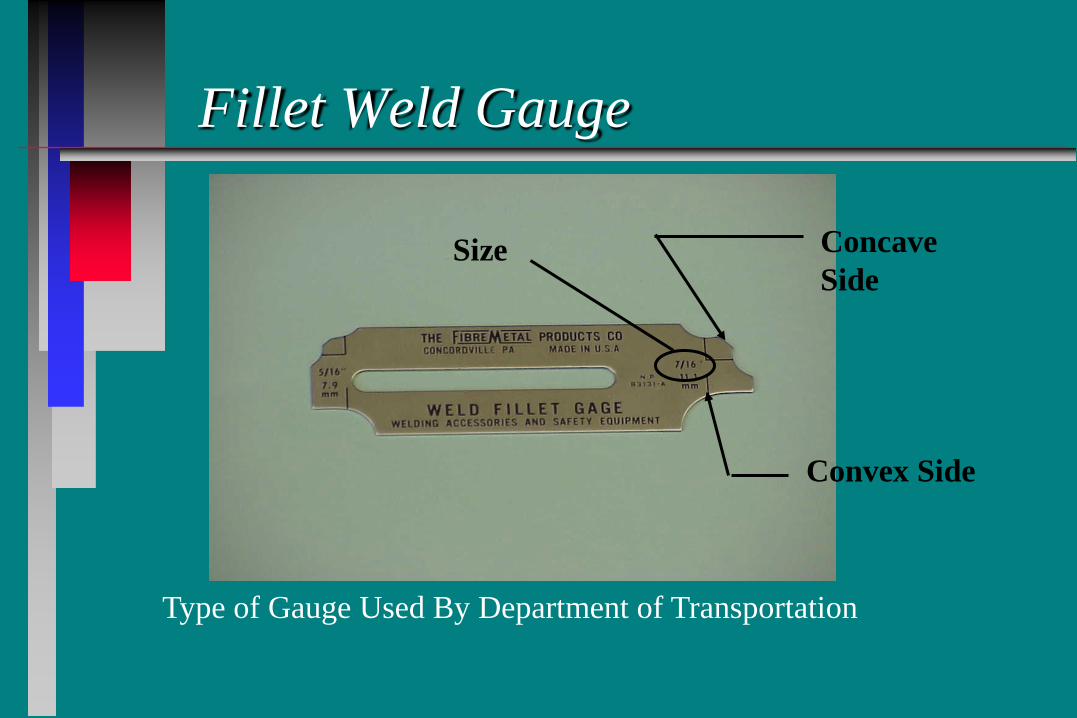
Fillet Weld Gauge
Type of Gauge Used By Department of Transportation
Concave Side
Convex Side
Size
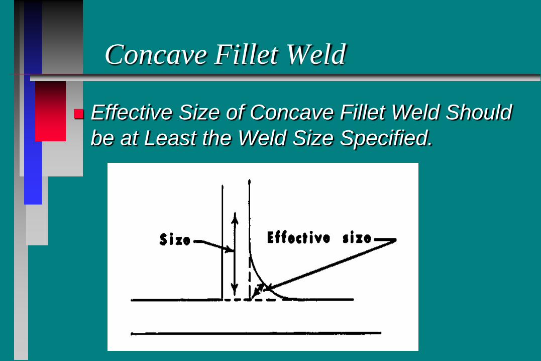
Concave Fillet Weld
Effective Size of Concave Fillet Weld Should be at Least the Weld Size Specified.

Concave Fillet Weld
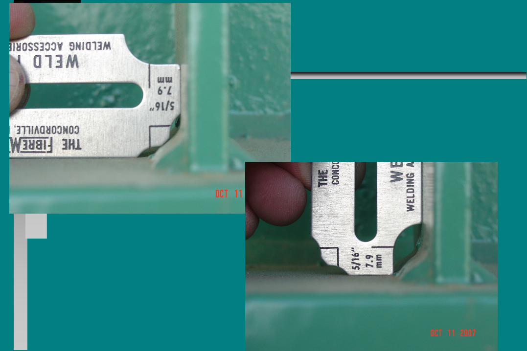
Weld Size Measured With Fillet Gauge
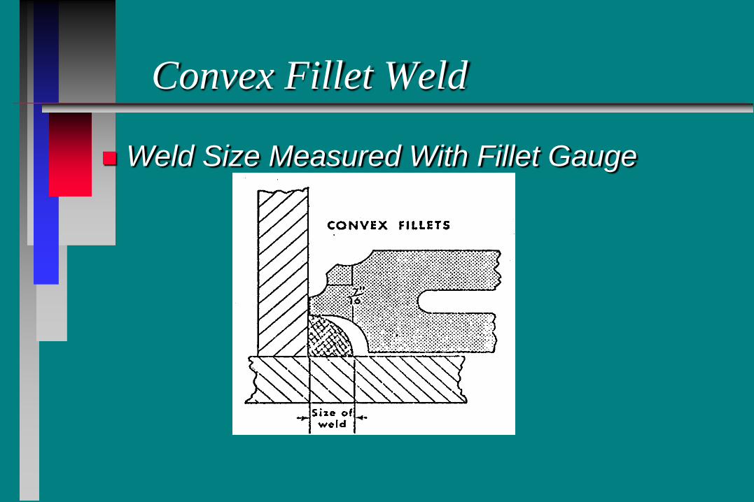
Convex Fillet Weld
Weld Size Measured With Fillet Gauge
Weld Defects
Types of Weld Defects: • Undercut • Overlap • Porosity • Cracks • Spatter
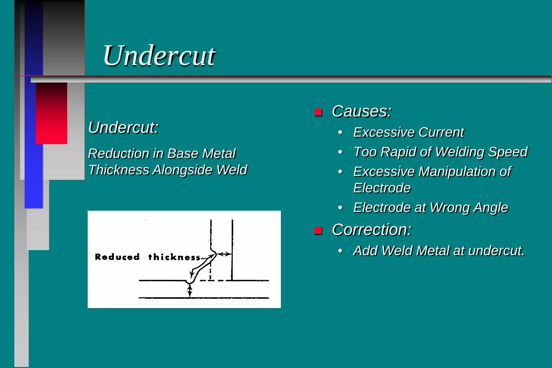
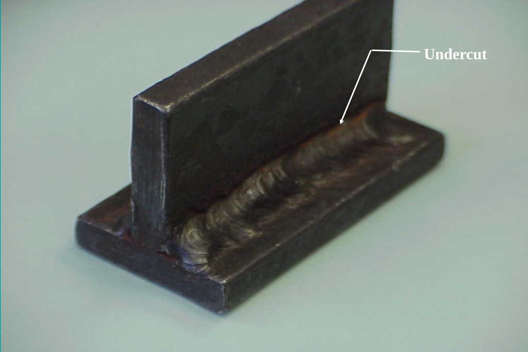
Undercut
Causes: • Excessive Current • Too Rapid of Welding Speed • Excessive Manipulation of
Electrode • Electrode at Wrong Angle
Correction: • Add Weld Metal at undercut.
Undercut: Reduction in Base Metal Thickness Alongside Weld
Undercut
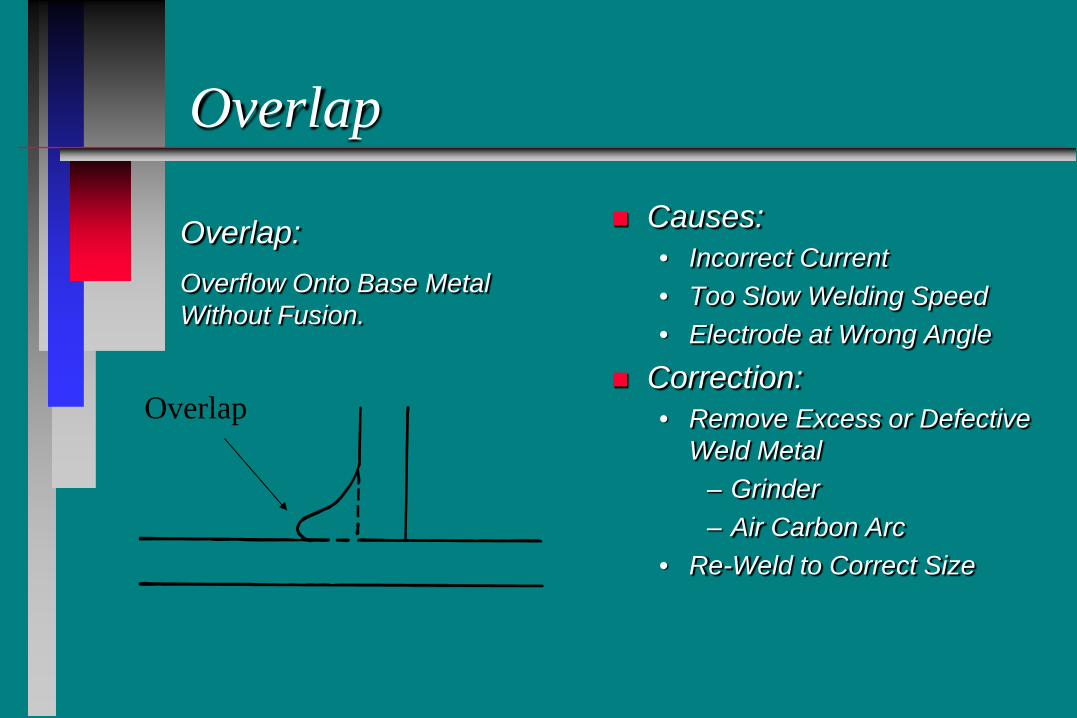
Overlap
Causes: • Incorrect Current • Too Slow Welding Speed • Electrode at Wrong Angle
Correction: • Remove Excess or Defective
Weld Metal – Grinder – Air Carbon Arc
• Re-Weld to Correct Size
Overlap
Overlap: Overflow Onto Base Metal Without Fusion.
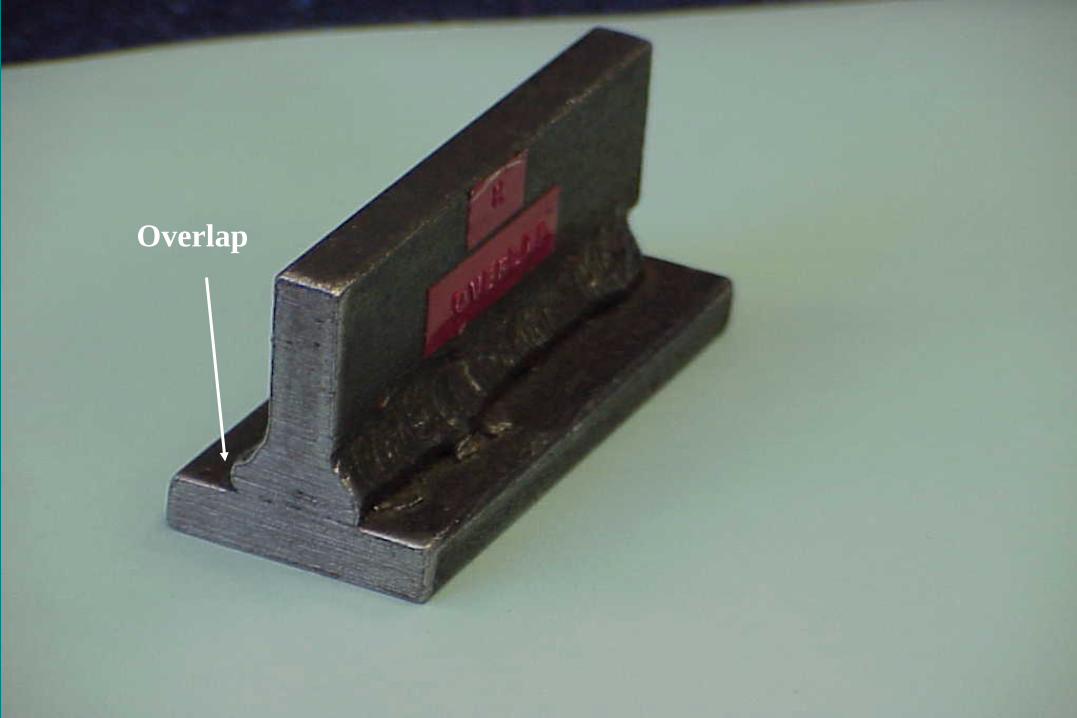
Overlap
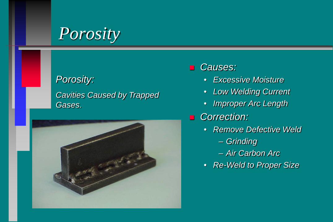
Porosity
Causes: • Excessive Moisture • Low Welding Current • Improper Arc Length
Correction: • Remove Defective Weld
– Grinding – Air Carbon Arc
• Re-Weld to Proper Size
Porosity: Cavities Caused by Trapped Gases.
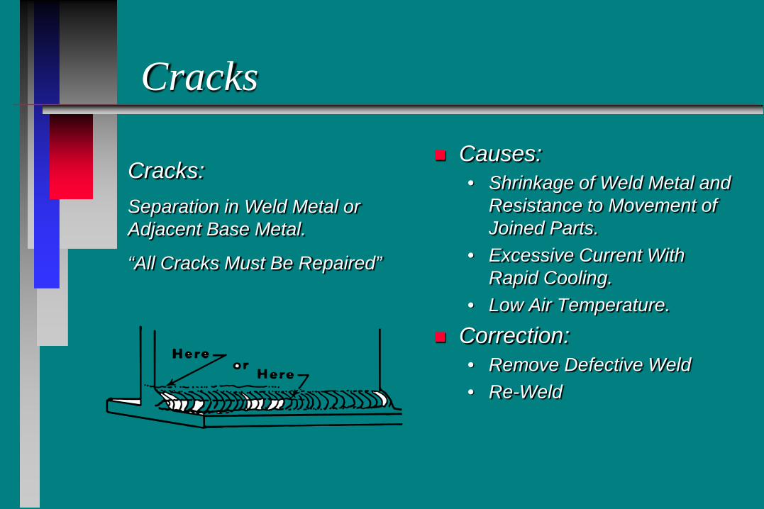
Cracks
Causes: • Shrinkage of Weld Metal and
Resistance to Movement of Joined Parts.
• Excessive Current With Rapid Cooling.
• Low Air Temperature.
Correction: • Remove Defective Weld • Re-Weld
Cracks: Separation in Weld Metal or Adjacent Base Metal.
“All Cracks Must Be Repaired”
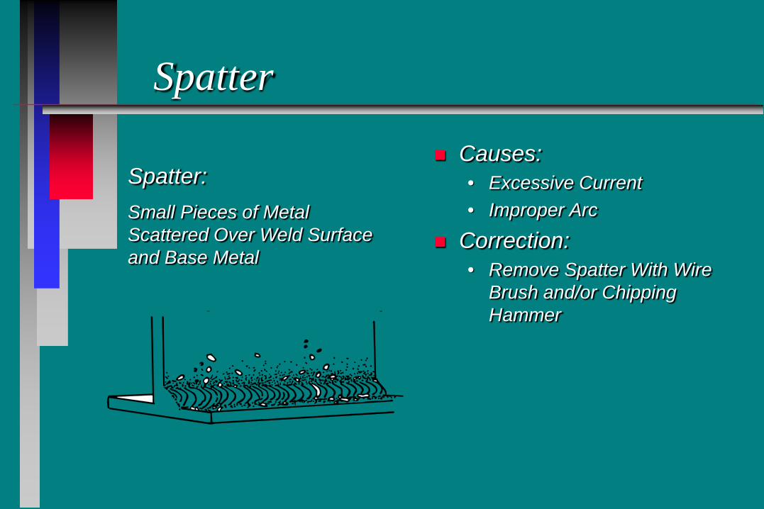
Spatter
Causes: • Excessive Current • Improper Arc
Correction: • Remove Spatter With Wire
Brush and/or Chipping Hammer
Spatter: Small Pieces of Metal Scattered Over Weld Surface and Base Metal
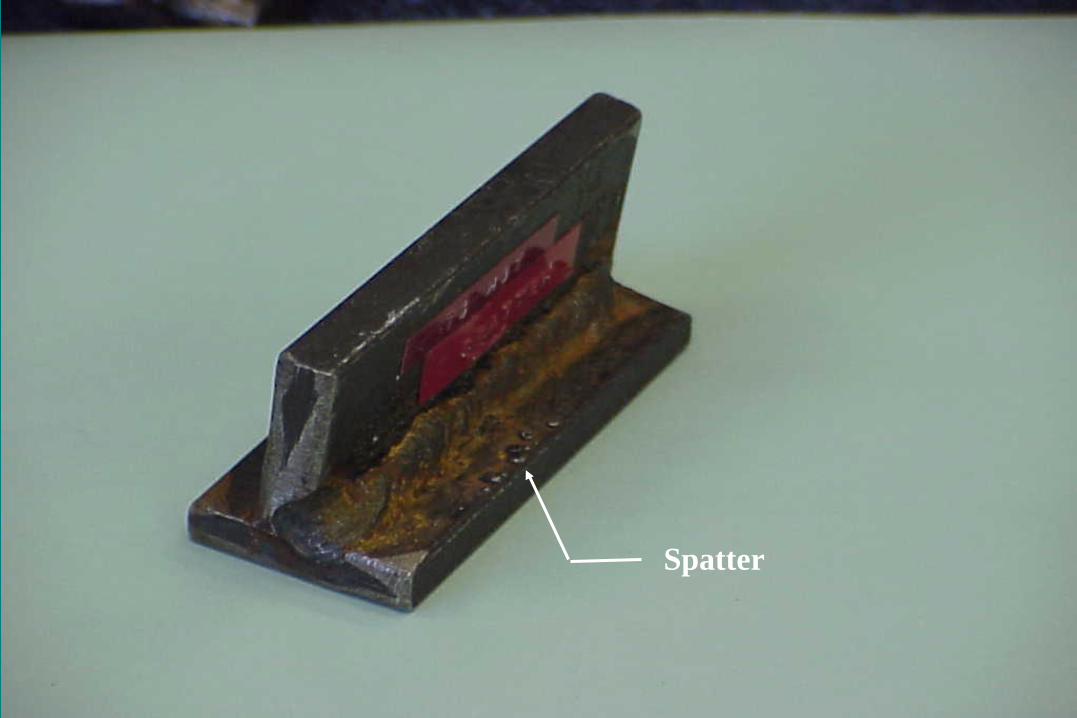
Spatter
Seal Weld
Occasionally Used to Seal Out Moisture
Not a Structural Weld
Should be Visually Inspected
Safty
Do not watch the welding with out a welding helmet
Do not touch the red hot stuff