field testing of an automatic transmission
TRANSCRIPT

FIELD TESTING OF AN AUTOMATIC
TRANSMISSION (AT) OF AN OFF-ROAD
VEHICLE
TADEUSZ DZIUBAK1, PAWEŁ SZCZEPANIAK2
Military University of Technology (WAT)
Summary
The construction and principle of operation of the conventional ZF-4HP24 automatic transmission
used in a Land Rover Range Rover P38A off-road vehicle has been discussed and results of field
testing of the automatic transmission (AT) have been presented. Within the field tests, automatic
transmission fluid (ATF) pressures were measured at diagnostic take-off points in the AT hydraulic
system. Moreover, the ATF viscosity was determined (at normal operating temperature) for fresh
fluid and for ATF samples taken from the AT under tests after a long period of normal operation of the
transmission. The field tests were carried out before and after servicing the AT, during which the AT
fluid and fluid suction filter were replaced. The field tests revealed that before replacement of the
fluid and fluid suction filter, the AT operated incorrectly, especially when the normal ATF operating
temperature was achieved.
Keywords: automatic transmissions (AT), automatic transmission fluid (ATF), kinematic viscosity, AT
pressure test
1. Introduction
The modern automatic transmission (AT) is a complicated unit which requires appropriate
operation and specialized maintenance. For most of the popular transmissions, the
maintenance consists in periodical checking of the fluid level and adding of the automatic
transmission fluid (ATF) if necessary [4, 12, 13]. Both vehicle operation experience and
experimental tests [3] show that the fluid characteristics deteriorate with AT operation
time and this has a negative impact on the functioning of such a transmission. Periodical
replacement of the ATF and the fluid suction filter often makes it possible to restore correct
AT functioning and to extend the time between overhaul of automatic transmissions.
The maintenance work, however, must be done with due care and diligence to prevent
contamination of the ATF and the hydraulic system with external substances [6, 7].
1 Military University of Technology (WAT), Faculty of Mechanical Engineering, Institute of Motor Vehicles and Transport,
ul. Kaliskiego 2, 00-908 Warsaw, Poland, e-mail: [email protected], ph. 22 683 71 21
2 Military University of Technology (WAT), Faculty of Mechanical Engineering, Institute of Motor Vehicles and Transport,
ul. Kaliskiego 2, 00-908 Warsaw, Poland, e-mail: [email protected]

Tadeusz Dziubak, Paweł Szczepaniak4
ZF Friedrichshafen AG, which manufactured the automatic transmission under tests,
recommends the ATF and the filter of the AT hydraulic system to be replaced after every
100 000 km travelled regardless of vehicle operation conditions and gearbox type [10].
Different recommendations are formulated by another AT manufacturer, i.e. Allison
Transmission, which divides the transmission duty cycles into “general” and “severe”. The
AT maintenance procedures consisting of ATF and filter replacement are to be scheduled
according to standard intervals that are defined as the numbers of kilometres travelled
by the vehicle (20 000 to 240 000 km), the numbers of hours of vehicle operation (500
to 4 000 h), or time between maintenance (6 to 48 months). These figures depend not
only on the duty cycle but also on the type of the automatic transmission involved [11].
The vehicle operation experience also shows that damage more often happens to the
automatic transmissions that are mounted in vehicles with high-power engines of high
torque output. It frequently happens in the workshop practice that replacement of working
fluid and fluid filter in a malfunctioning automatic transmission brings the transmission
back to full working order. For the servicing of an automatic transmission, high-quality
replacement materials (automatic transmission fluids and fluid filters) recommended
by the transmission manufacturer for the specific AT model should be used. The use of
an inappropriate ATF or filter will result in damage to the automatic transmission [8]. The
objective of this work was to carry out experimental tests that were to show whether
the AT servicing consisting of the replacement of automatic transmission fluid and fluid
suction filter would result in an improvement of operation of a malfunctioning automatic
transmission after a long period of the transmission being in service (in a vehicle that
travelled about 150 000 km). Within the experimental tests carried out during normal
vehicle drives, ATF pressures were measured at diagnostic take-off points in the AT
hydraulic system before and after servicing the AT.
2. Object of testing
The experimental field tests were carried out on a ZF-4HP24 automatic transmission
used in a Land Rover Range Rover 4.6 HSE off-road vehicle for two cases as regards the
technical condition of the transmission, i.e. before and after servicing the transmission. The
transmission under tests was a conventional automatic transmission with a hydrokinetic
torque converter and with four forward drive ratios and a reverse gear. In the automatic
transmission model under test, the AT is controlled with the use of an EAT (electronic
automatic transmission) system, where engine and vehicle operation parameters (load,
accelerator pedal position, engine speed, vehicle speed) are taken as system inputs.
The EAT system output signals govern the operation of the electrohydraulic AT controller,
which directs the ATF flow to appropriate actuators that engage clutches and lock
multidisc wet brakes to couple together or immobilize selected components of individual
epicyclic gearsets. Apart from the gearbox proper, the ZF-4HP24 automatic transmission
system includes other components, such as drive mode selector, electronic automatic
transmission (EAT) controller, drive mode selector lever mechanically connected via
a cable with the drive mode selector, and ATF cooler, which makes it possible to keep
the ATF temperature close to 80 °C. The AT model under tests is provided with an “H gate”

Field testing of an automatic transmission (AT) of an off-road vehicle 5
Fig. 1. The ZF-4HP24 automatic transmission system: a) automatic transmission component layout; b) drive
mode selector lever assembly with an “H gate” mechanism [17];
1 – drive mode selector lever assembly; 2 – automatic transmission (AT) ZF-4HP24;
3 – electronic AT (EAT) controller; 4 – drive mode selector position switch;
5 – ATF cooler; 6 – ATF lines; 7 – AT breather tube; 8 – drive mode selector cable
drive mode selector mechanism (Fig. 1b), which combines the functions of controlling the
operation of the automatic transmission and a mechanical reduction gear engaged by
means of an electric actuator. The high-speed ratios (“Hi”) are obtained when the automatic
transmission operates alone; for the vehicle to operate in the range of low-speed ratios
(“Lo”), the mechanical reduction gear must be additionally engaged by shifting the selector
lever to the side marked “Lo”.
The power and torque is transmitted from the engine crankshaft to the automatic
transmission by a hydrokinetic torque converter [4, 5, 10–13, 20]. The torque converter
consists of impeller integral with the pump body fixed through a drive plate to engine
crankshaft, turbine connected with the gearbox input shaft, and stator. Adequate clearance
between these parts is ensured by sliding thrust rings and bearings. The torque converter is
completely filled up with the automatic transmission fluid. The ATF is drawn by the impeller
through the passage around the impeller axis and is moved by centrifugal forces to turbine
vanes. The kinetic energy of the ATF hitting the turbine vanes causes the latter to rotate, in
result of which the energy is transmitted to the turbine and is converted into the energy of
rotational motion of the turbine. Then, the fluid is again drawn to the space surrounding the
converter axis, i.e. to the zone of lower pressure, and thus it returns to the impeller vanes.
The ATF flow inside the torque converter depends on the difference between the rotational
speeds of the impeller and the turbine. At high values of this difference, the ATF leaving the
turbine hits the impeller vanes, trying to rotate the impeller in the opposite direction. Such
a phenomenon would result in resistance to impeller motion, i.e. in energy losses, but it is
eliminated by the action of vanes of the converter stator placed between the turbine and

Tadeusz Dziubak, Paweł Szczepaniak6
the impeller. The ATF flowing out of the turbine hits the front surfaces of the stator vanes,
trying to rotate the stator in the direction opposite to that of impeller rotation. However, the
stator is blocked by the action of a one-way clutch, i.e. it does not rotate; in consequence,
the fluid flow direction is changed to boost the impeller rotation. The directed ATF flow
inside the converter causes the torque applied as an input to the impeller to be doubled
or even tripled by the converter at high values of the slip between the impeller and the
turbine, which occurs during vehicle start-up or acceleration. On the other hand, it is worth
remembering that the higher the slip, the lower the converter efficiency. At high slip, the
energy of rotational motion of the converter impeller is partly transformed into heat in the
automatic transmission fluid.
Fig. 2. The ZF-4HP24 automatic transmission: 1 – lock-up clutch; 2 – pump body with impeller ; 3 – turbine;
4 – multidisc forward drive clutch; 5 – multidisc reverse drive clutch; 6, 7, 8 – multidisc brake; 9 – Simpson
epicyclic gearset; 10 – simple epicyclic gearset; 11 – multidisc clutch; 12 – multidisc brake; 13 – output shaft;
14, 15, 16 – freewheel mechanism (one way clutch); 17 – torque converter stator with one way clutch [17]
To prevent energy losses and fluid overheating, modern torque converters are provided
with a “lock-up” friction clutch, which consists of a piston actuator and a friction disc.
The piston can slide along the torque converter axis. When the piston moves towards
the pump body, it presses the friction disc against the internal surface of the pump body
for the pump impeller to be coupled with the turbine. The EAT controller outputs a signal
which, operating a valve in the electrohydraulic controller, causes the ATF to flow through
a passage in the turbine shaft to the piston actuator that engages the lock-up clutch. In the
ZF-4HP24 automatic transmission, the lock-up clutch of the torque converter is engaged
when the vehicle is driven with a speed of 48–72 km/h in the 4th gear [16]. The centrepiece
of every conventional automatic transmission is a system of epicyclic gearsets, which
implement specific gear ratios. Theoretically, a single epicyclic gearset can offer seven
gearset ratios, including one direct drive and two reversing gears. In practice, two usable
gearset ratios are obtained from one simple epicyclic gearset. For this reason, compound
planetary gearsets are used in automatic transmissions, e.g. Simpson and Ravigneaux
systems [4, 5, 16]. The ratios of the compound planetary gearsets can be changed
Field testing of an automatic transmission (AT) of an off-road vehicle 7
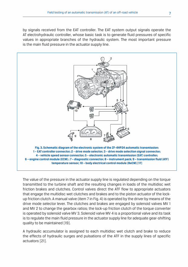
Fig. 3. Schematic diagram of the electronic system of the ZF-4HP24 automatic transmission:
1 – EAT controller connector; 2 – drive mode selector; 3 – drive mode selection signal connector;
4 – vehicle speed sensor connector; 5 – electronic automatic transmission (EAT) controller;
6 – engine control module (ECM) ; 7 – diagnostic connector; 8 – instrument pack; 9 – transmission fluid (ATF)
temperature sensor; 10 – body electrical control module (BeCM) [17]
by signals received from the EAT controller. The EAT system output signals operate the
AT electrohydraulic controller, whose basic task is to generate fluid pressures of specific
values in appropriate branches of the hydraulic system. The most important pressure
is the main fluid pressure in the actuator supply line.
The value of the pressure in the actuator supply line is regulated depending on the torque
transmitted to the turbine shaft and the resulting changes in loads of the multidisc wet
friction brakes and clutches. Control valves direct the ATF flow to appropriate actuators
that engage the multidisc wet clutches and brakes and to the piston actuator of the lock-
up friction clutch. A manual valve (item 7 in Fig. 4) is operated by the driver by means of the
drive mode selector lever. The clutches and brakes are engaged by solenoid valves MV 1
and MV 2 to change the gearbox ratios; the lock-up friction clutch of the torque converter
is operated by solenoid valve MV 3. Solenoid valve MV 4 is a proportional valve and its task
is to regulate the main fluid pressure in the actuator supply line for adequate gear-shifting
quality to be maintained [19].
A hydraulic accumulator is assigned to each multidisc wet clutch and brake to reduce
the effects of hydraulic surges and pulsations of the ATF in the supply lines of specific
actuators [21].
Tadeusz Dziubak, Paweł Szczepaniak8
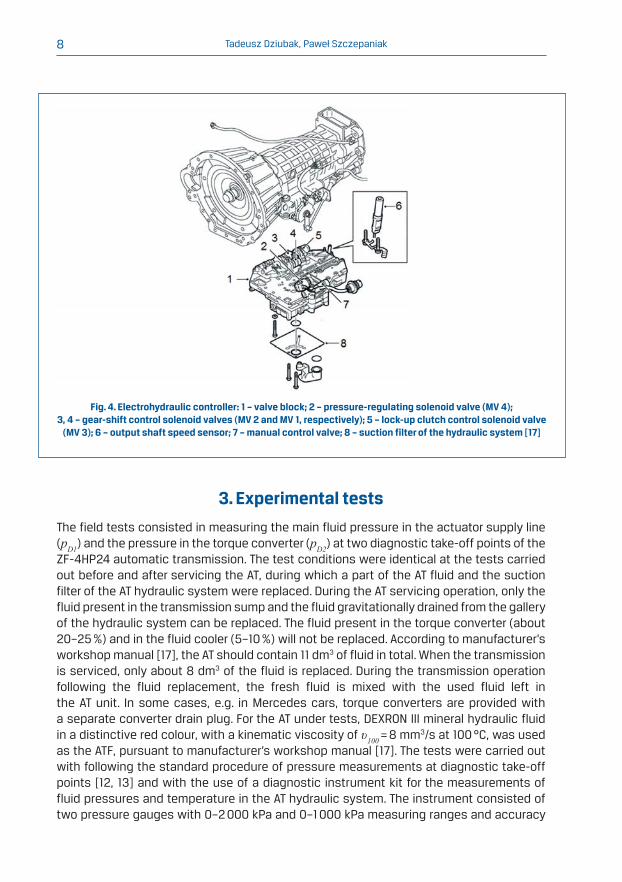
Fig. 4. Electrohydraulic controller: 1 – valve block; 2 – pressure-regulating solenoid valve (MV 4);
3, 4 – gear-shift control solenoid valves (MV 2 and MV 1, respectively); 5 – lock-up clutch control solenoid valve
(MV 3); 6 – output shaft speed sensor; 7 – manual control valve; 8 – suction filter of the hydraulic system [17]
3. Experimental tests
The field tests consisted in measuring the main fluid pressure in the actuator supply line
(pD1) and the pressure in the torque converter (pD2) at two diagnostic take-off points of the
ZF-4HP24 automatic transmission. The test conditions were identical at the tests carried
out before and after servicing the AT, during which a part of the AT fluid and the suction
filter of the AT hydraulic system were replaced. During the AT servicing operation, only the
fluid present in the transmission sump and the fluid gravitationally drained from the gallery
of the hydraulic system can be replaced. The fluid present in the torque converter (about
20–25 %) and in the fluid cooler (5–10 %) will not be replaced. According to manufacturer’s
workshop manual [17], the AT should contain 11 dm3 of fluid in total. When the transmission
is serviced, only about 8 dm3 of the fluid is replaced. During the transmission operation
following the fluid replacement, the fresh fluid is mixed with the used fluid left in
the AT unit. In some cases, e.g. in Mercedes cars, torque converters are provided with
a separate converter drain plug. For the AT under tests, DEXRON III mineral hydraulic fluid
in a distinctive red colour, with a kinematic viscosity of υ100 = 8 mm3/s at 100 °C, was used
as the ATF, pursuant to manufacturer’s workshop manual [17]. The tests were carried out
with following the standard procedure of pressure measurements at diagnostic take-off
points [12, 13] and with the use of a diagnostic instrument kit for the measurements of
fluid pressures and temperature in the AT hydraulic system. The instrument consisted of
two pressure gauges with 0–2 000 kPa and 0–1 000 kPa measuring ranges and accuracy

Field testing of an automatic transmission (AT) of an off-road vehicle 9
Fig. 5. Schematic diagram of the measuring system: 1 – the ZF-4HP24 automatic transmission;
2 – pressure gauge with 0–2 000 kPa measuring range; 3 – pressure gauge with 0–1 000 kPa measuring range;
4 – all-purpose multimeter; 5 – flexible hydraulic pipes with adapters; 6 – ATF temperature measuring probe
with an electrical cable; D1 – take-off point to measure the main supply pressure pD1;
D2 – take-off point to measure pressure pD2 in the torque converter; DT – take-off point to measure the ATF
temperature in the transmission sump
class 1 and a multimeter with 0–400 °C measuring range and accuracy of ±1 °C. The engine
speed was read from the tachometer of the vehicle instrument panel.
The fluid pressures were measured when the vehicle was moving and the ATF temperature
was stabilized at 80±2 °C, in the full range of gearbox ratios (in gears from 1 to 4), at engine
speeds ranging from 1 000 rpm to 4 500 rpm, with the drive mode selector lever set to “D”,
pursuant to the automatic transmission testing method having been developed.
1. The diagnostic instrument kit, consisting of measuring pressure gauges and
a multimeter, was installed on the dashboard in the vehicle passenger compartment.
2 The measuring pressure gauges were connected by means of flexible hydraulic pipes
(5 in Fig. 6) and mechanical adapters to diagnostic take-off points D1 and D2 of the
ZF-4HP24 automatic transmission.
3. A temperature probe (6 in Fig. 6) of the multimeter (4 in Fig. 6) was installed at the end
of the ATF dipstick (the DT temperature measurement point).
4. The engine was started and the vehicle was driven to travel 30 km in urban traffic
conditions for the whole ATF volume in the automatic transmission to reach the
prescribed working temperature (of 80±2 °C, according to publications [17, 20]).
Tadeusz Dziubak, Paweł Szczepaniak10
5. When the ATF working temperature in the automatic transmission was stabilized,
measurements of the main fluid pressure in the actuator supply line (pD1) and the
pressure in the torque converter (pD2) at two diagnostic take-off points of the ZF-4HP24
automatic transmission were started. This was done as follows:
• The vehicle was placed on a straight road section about 3 km long in a closed area.
• The drive mode selector lever was set to “D/1”, the vehicle was started to move, and
engine speed was set to values from ns = 1 000 rpm to ns = 4 500 rpm in 500 rpm
intervals, according to vehicle tachometer readings.
• For each stabilized engine speed, three measurements of the main fluid pressure in the
actuator supply line (pD1) and the pressure in the torque converter (pD2) were taken in
10 s time intervals, with checking simultaneously the current ATF working temperature.
• An identical procedure was followed to measure the pD1 and pD2 pressures in successive
gears up to “4”.
• Each measurement result was taken as the arithmetic mean of the three pressure
values read for a specific engine speed ns and a specific gearbox ratio implemented.
To carry out measurements for gearbox ratios “1” to “3” being implemented, a function of
the electronic automatic transmission (EAT) controller was used that makes it possible to
eliminate the highest gearbox ratios. When the drive mode selector lever is set to “D/1”, only
one gearbox ratio can be used. When the lever is shifted to “D/2”, the vehicle can be driven
in gears “1” and “2”. Similarly, for the “D/3” lever position the gears that can be used are “1”,
“2”, and “3” and the shifting of the lever to “D” enables the use of all the four gearbox ratios.
4. Analysis of results of the field tests
Results of measurements of the main fluid pressure in the actuator supply line (pD1) and
of the pressure in the torque converter (pD2) in the hydraulic system of the automatic
transmission have been presented in Figs. 6, 9, and 12. When analysing the pressure
curves obtained, one may notice effects of operation of the proportional valve MV 4,
which changes the ATF flow and regulates the pressure in the line that supplies fluid to
the hydraulic actuators of the automatic transmission depending on signals coming from
the EAT controller [16, 17]. There is no ATF pressure sensor in the hydraulic control system;
therefore, the output pressure of the MV 4 valve cannot be regulated in a system of closed
loop feedback with the EAT controller. If the hydraulic system is insufficiently effective
due to excessive internal ATF leaks between mating parts or because excessive filter
flow resistance prevents the hydraulic pump from adequate sucking of the fluid [4], the
values of the pressures regulated by the MV 4 valve will be lower than they would be if the
hydraulic system were fully efficient. It should be stressed here that the value of the main
fluid pressure in the actuator supply line at a specific state of operation of the automatic
transmission is chiefly determined by the degree of wear and tear of system components.
Variations in the pressure pD1 of ATF supply to hydraulic actuators of the automatic

Field testing of an automatic transmission (AT) of an off-road vehicle 11
Fig. 6. ATF supply pressures for fresh and used fluid, with drive mode selector switch set to “D”:
a) – gear “1”; b) – gear “2”
transmission vs. the engine speed ns (the hydraulic pump rotor speed) for gearbox ratios
“1” and “2” have been shown in Fig. 6.
With increasing engine speed ns, the ATF pressure in the hydraulic system grows, regardless
of the technical condition of the automatic transmission. The value of the actuator supply
pressure pD1 is limited by the operation of pressure-regulating valve MV 4. Before the
servicing, the actuator supply pressure pD1 measured when gear ratio “1” was implemented
in the transmission changed from pD1 = 610 kPa at an engine speed of ns = 1 000 rpm to
pD1 = 750 kPa at an engine speed of ns = 4 500 rpm. After the servicing, the actuator supply
pressure pD1 for the transmission operating in gear “1” changed from pD1 = 700 kPa at an
engine speed of ns = 1 000 rpm to pD1 = 780 kPa at an engine speed of ns = 4 500 rpm.
This means that the fluid pressures after the servicing grew by 12.8 % for ns = 1 000 rpm
and by 4.29% for ns = 4 500 rpm, which can be easily explained by higher viscosity of the
fresh fluid (after the replacement) and, in consequence, lower hydraulic losses at the
“piston-cylinder” pairs in the actuators and between the mating parts in the gear pump.
The replacement of the suction filter with a new unit, having lower suction resistance,
also results in an increase in the pump delivery rate and in the fluid pressure built in the
hydraulic system.
According to data given in the service manual [20], the fluid supply pressure at the idle
engine speed (about ns = 1 000 rpm) and with the selector lever set to D/1 should be
within a range of pD1 = 630–710 kPa. The actuator supply pressure pD1 measured before
the servicing was lower by 20 kPa than the lower acceptable limit; after the servicing,
it was in the upper part of the tolerance range (Fig. 6a). In gear “1”, the ATF is supplied
to clutches 4 and 11. The driving power is transmitted through epicyclic gearsets, with
Tadeusz Dziubak, Paweł Szczepaniak12
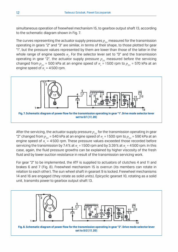
Fig. 7. Schematic diagram of power flow for the transmission operating in gear “1”. Drive mode selector lever
set to D/1 [17, 20]
Fig. 8. Schematic diagram of power flow for the transmission operating in gear “2”. Drive mode selector lever
set to D/2 [17, 20]
simultaneous operation of freewheel mechanism 15, to gearbox output shaft 13, according
to the schematic diagram shown in Fig. 7.
The curves representing the actuator supply pressures pD1 measured for the transmission
operating in gears “2” and “3” are similar, in terms of their shape, to those plotted for gear
“1”, but the pressure values represented by them are lower than those of the latter in the
whole range of engine speeds ns. For the selector lever set to “D” and the transmission
operating in gear “2”, the actuator supply pressure pD1 measured before the servicing
changed from pD1 = 500 kPa at an engine speed of ns = 1 500 rpm to pD1 = 570 kPa at an
engine speed of ns = 4 500 rpm.
After the servicing, the actuator supply pressure pD1 for the transmission operating in gear
“2” changed from pD1 = 540 kPa at an engine speed of ns = 1 500 rpm to pD1 = 590 kPa at an
engine speed of ns = 4 500 rpm. These pressure values exceeded those recorded before
servicing the transmission by 7.4 % at ns = 1 500 rpm and by 3.39 % at ns = 4 500 rpm. In this
case, again, the fluid pressure growths can be explained by higher viscosity of the fresh
fluid and by lower suction resistance in result of the transmission servicing work.
For gear “2” to be implemented, the ATF is supplied to actuators of clutches 4 and 11 and
brakes 6 and 7 (Fig. 8). Freewheel mechanism 15 is overrun (its members can rotate in
relation to each other). The sun wheel shaft in gearset 9 is locked. Freewheel mechanisms
14 and 16 are engaged (they rotate as solid units). Epicyclic gearset 10, rotating as a solid
unit, transmits power to gearbox output shaft 13.

Field testing of an automatic transmission (AT) of an off-road vehicle 13
Fig. 9. ATF supply pressures for fresh and used fluid, with drive mode selector switch set to “D”:
a) – gear “3”; b) – gear “4”
It can be seen in the power flow diagrams for the ZF-4HP24 automatic transmission that
when gear “1” is implemented in the gearbox (Fig. 7), only two actuators (that engage
clutches 4 and 11) are supplied with the ATF. In gear “2”, the electrohydraulic controller
directs the ATF flow not only to the actuators of clutches 4 and 11 but also to the actuators
of brakes 6 and 7. The larger number of the actuators supplied with the fluid translates into
a possibility of higher hydraulic leakage rates and, in consequence, bigger drops in the fluid
supply pressure at similar settings of pressure-regulating valve MV 4.
When the selector lever was set to “D” and gear “3” was implemented in the gearbox (Fig.
9a), the actuator supply pressure pD1 before the servicing changed from pD1 = 500 kPa at
an engine speed of ns = 1 500 rpm to pD1 = 590 kPa at an engine speed of ns = 4 500 rpm.
After the servicing, the actuator supply pressure pD1 for the transmission operating in gear
“3” changed from pD1 = 560 kPa at an engine speed of ns = 1 500 rpm to pD1 = 620 kPa at
an engine speed of ns = 4 500 rpm, i.e. these pressure values exceeded the corresponding
figures recorded before servicing the transmission by 10.7 % at ns = 1 500 rpm and by 4.84 %
at ns = 4 500 rpm.
Gear “3” is implemented in the transmission when clutches 4, 5, and 11 and brake 7 are
engaged (Fig. 10). Freewheel mechanisms 15 and 16 are overrun. Epicyclic gearset 10
transmits power to gearbox output shaft 13.
When the selector lever was set to “D” and gear “4” was implemented in the gearbox (Fig.
9b), the actuator supply pressure pD1 before the servicing changed from pD1 = 590 kPa at
an engine speed of ns = 1 500 rpm to pD1 = 640 kPa at an engine speed of ns = 4 500 rpm.
After the servicing, the actuator supply pressure pD1 for the transmission operating in gear
“4” was pD1 = 650 kPa at an engine speed of ns = 1 500 rpm and pD1 = 780 kPa at an engine

Tadeusz Dziubak, Paweł Szczepaniak14
Fig. 10. Schematic diagram of power flow for the transmission operating in gear “3”. Drive mode selector lever
set to D/3 [17, 20]
Fig. 11. Schematic diagram of power flow for the transmission operating in gear “4”. Drive mode selector lever
set to D/4 [17, 20]
speed of ns = 4 500 rpm, i.e. these pressure values exceeded the corresponding figures
recorded before servicing the transmission by 9.23 % at ns = 1 500 rpm and by 17.9 % at
ns = 4 500 rpm.
For gear “4” to be implemented, the ATF is supplied to actuators of clutches 4 and 5 and
brakes 7 and 12 (Fig. 11). Freewheel mechanisms 14, 15, and 16 are overrun. The sun wheel
shaft in gearset 10 is locked. Epicyclic gearset 10 transmits power to gearbox output shaft
13.
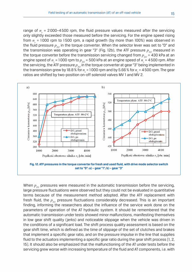
Curves representing the ATF pressure pD2 in the AT torque converter vs. the engine speed
at the drive mode selector lever set to D and at gears “1” and “3” being implemented in
the transmission have been shown in Fig. 12. Before the servicing, the fluid pressure pD2 in the AT torque converter at the drive mode selector lever set to D and at gear “1” being
implemented (Fig. 12a) changed from pD2 = 300 kPa at an engine speed of ns = 1 000 rpm
to pD2 = 660 kPa at an engine speed of ns = 4 500 rpm. After the servicing, the ATF pressure
pD2 in the torque converter was pD2 = 360 kPa at ns = 1 000 rpm and pD2 = 660 kPa at
ns = 4 500 rpm, i.e. it was higher by 16.7% than the figure recorded before the servicing
at ns = 1 000 rpm and it remained unchanged at ns = 4 500 rpm.
The pressure vs. engine speed curves, representing the ATF pressure pD2 measured before
and after the servicing in the AT torque converter for gear “1” being implemented in the
gearbox, are almost identical to each other in terms of their shape. In the engine speed
Field testing of an automatic transmission (AT) of an off-road vehicle 15
Fig. 12. ATF pressures in the torque converter for fresh and used fluid, with drive mode selector switch
set to “D”: a) – gear “1”; b) – gear “3”
range of ns = 2 000–4 500 rpm, the fluid pressure values measured after the servicing
only slightly exceeded those measured before the servicing. For the engine speed rising
from ns = 1 000 rpm to 1 500 rpm, a rapid growth (by more than 100%) was observed in
the fluid pressure pD2 in the torque converter. When the selector lever was set to “D” and
the transmission was operating in gear “3” (Fig. 12b), the ATF pressure pD2 measured in
the torque converter before the transmission servicing changed from pD2 = 430 kPa at an
engine speed of ns = 1 000 rpm to pD2 = 500 kPa at an engine speed of ns = 4 500 rpm. After
the servicing, the ATF pressure pD2 in the torque converter at gear “3” being implemented in
the transmission grew by 18.8 % for ns = 1 000 rpm and by 5.66 % for ns = 4 500 rpm. The gear
ratios are shifted by two-position on-off solenoid valves MV 1 and MV 2.
When pD1 pressures were measured in the automatic transmission before the servicing,
large pressure fluctuations were observed but they could not be evaluated in quantitative
terms because of the measurement method adopted. After the ATF replacement with
fresh fluid, the pD1 pressure fluctuations considerably decreased. This is an important
finding, informing the researchers about the influence of the service work done on the
parameters of operation of the AT hydraulic system. It should be remembered that the
automatic transmission under tests showed minor malfunctions, manifesting themselves
in low gear shift quality (jerks) and noticeable slippage when the vehicle was driven in
the conditions of a significant load. The shift process quality assessment is based on the
gear shift time, which is defined as the time of slippage of the set of clutches and brakes
that implement a specific gear ratio, and on the pressure impulse in the line that supplies
fluid to the actuators implementing a specific gear ratio during the gear shift process [1, 2,
15]. It should also be emphasized that the malfunctioning of the AT under tests before the
servicing grew worse with increasing temperature of the fluid and AT components, i.e. with

Tadeusz Dziubak, Paweł Szczepaniak16
Fig. 13. Kinematic viscosity υ80 of ATF DEXRON IID/III samples taken from the transmission of a vehicle that had
travelled Sp = 148 345 km in total (“used” fluid) and of fresh ATF (“fresh” fluid)
decreasing fluid viscosity and pressure in the hydraulic system. The ATF replacement with
fresh fluid (having higher kinematic viscosity) and the replacement of the suction filter
with a new unit were found to result in an increase in the fluid pressure in the hydraulic
actuator supply line in specific AT operation states and in elimination of the transmission
malfunctions.
Additionally, kinematic viscosity of the DEXRON IID/III fluid was determined for fluid
samples taken from the AT under tests before the servicing (when the vehicle had travelled
Sp = 148 345 km in total) and for samples of the fresh fluid used for replacement when the
transmission was serviced (Fig. 13).
The ATF viscosity tests were carried out at a temperature of 80 °C corresponding to the
normal working temperature of the AT under tests. Pursuant to Polish Standard PN-EN ISO
3104:2004, the ATF viscosity shall be determined at temperatures of 40 °C and 100 °C [14].
In authors’ opinion, however, the measurements of fluid viscosity at a temperature of 80 °C
could help to identify the reasons for malfunctions of the automatic transmission under
tests.
The drop in viscosity of the DEXRON IID/III fluid samples taken from the automatic
transmission under tests in comparison with the viscosity of fresh automatic transmission
fluid (ATF), determined at a temperature of 80 °C, was Δυ80 = 23.15 %. The drop in viscosity
of used ATF (in relation to fresh fluid viscosity) was on a level similar to that of a fluid
sample taken from a conventional AT having travelled about 100 000 km, experimentally
tested at temperatures of 40 °C (Δυ40 = 24.49 %) and 100 °C (Δυ100 = 19.95 %) [3].
5. Recapitulation
The results obtained from tests of ATF pressures at diagnostic take-off points of the
hydraulic system of a ZF-4HP24 automatic transmission have shown that changes
in the working characteristics of the automatic transmission fluid and in the technical
Field testing of an automatic transmission (AT) of an off-road vehicle 17
condition of the suction filter (flow resistance) may have an impact on the functioning of
an automatic transmission that was in service for a long time (in a vehicle that travelled
about 150 000 km). The diagnostic instrument kit used for the experimental field tests
did not offer a possibility of qualitative assessment of the operation of an automatic
transmission, including the shift process quality and size of fluctuations of the fluid
supply pressure. For such an assessment to be carried out, time histories of the pressures
of fluid supplied to hydraulic actuators should be recorded during a road test. The records
obtained would make it possible to determine the time of specific gear shift processes
and the nature of the ATF pressure vs. time curves [1, 2, 9, 15]. A drop in the ATF pressure
in the hydraulic system of an automatic transmission in specific vehicle movement
conditions will result in a proportional decrease in the force exerted by the actuator on
a multidisc brake or clutch to implement the selected gear ratio and this is connected
with excessive brake or clutch slippage. The excessive slippage, in turn, will cause
“burning” and “flaking” of friction clutch linings made from cellulose or aramid fibre, or even
welding of such materials [18, 19]. With increasing slippage, the ATF temperature locally
rises in the friction zone, causing excessive oxidation of the fluid; moreover, high relative
velocities between friction surfaces intensify the ATF shearing process [19]. Changes in
the physical and chemical ATF properties result in malfunctioning of the hydraulic system.
The malfunctioning, in turn, leads to deterioration in the physical and chemical properties
of the ATF. The malfunctioning of the automatic transmission under tests before the
servicing grew worse with increasing fluid temperature, i.e. with decreasing fluid viscosity.
This may be connected with significant wear and tear of AT components, which resulted in
excessive internal leaks in the part supplied with ATF under the main pressure generated in
the hydraulic system. Replacement of the ATF with fresh fluid, whose kinematic viscosity
at the working temperature is higher than that of the fluid after a long period of being in
service (by more than 20 %) results in so big a reduction in hydraulic leaks at the “piston-
cylinder” pairs in the actuators that adequate functioning of the AM hydraulic system can
thus be restored in spite of significant wear and tear of AT components.
References[1] J. GYU-HONG J., BAEK-HYUN CH., KYO-II L.: Dynamic Analysis and Closed-loop Shifting Control of EF-Automatic
Transmission with Proportional Control Solenoid Valves. FISITA World Automotive Congress, Seoul, Korea,
2000.
[2] KUO K.L.: Simulation and Analysis of the Shift Process for an Automatic Transmission. World Academy of
Science, Engineering and Technology, 2011.
[3] DZIUBAK T., SZCZAWIŃSKI P., SZCZEpaniak P.: Wpływ przebiegu eksploatacyjnego płynu ATF na jakość pracy i
trwałość automatycznych skrzyń biegów (ASB) samochodów osobowych, Biul. WAT, 62, 2013.
[4] SOBIERAJ W.: Poradnik Serwisowy – automatyczne skrzynie biegów. Instalator Polski, Warszawa, 2005.
[5] MICKNASS W., POPIOL R., SPRENGER A.: Sprzęgła, skrzynki biegów, wały i półosie napędowe. Warszawa,
Wydawnictwa Komunikacji Łączności, 2005.
[6] Filter Manufacturers Council: Non-Serviceable Automotive Transmission Filters. Technical Service Bulletin 97-
6, North Carolina, USA, 2009.
[7] Filter Manufacturers Council: Automotive Transmission Fluid Evacuation Service. Technical Service Bulletin
98-2, North Carolina, USA, 2011.

Tadeusz Dziubak, Paweł Szczepaniak18
[8] Filter Manufacturers Council: Hydraulic Filter Performance Criteria. Technical Service Bulletin 97-1, North
Carolina, USA, 2009.
[9] KIM J.C., CHEONG S.Y., CHEONG Y.M.: Prediction of Cumulative Damage by Analysis of AutomaticTransmission
Endurance Test Mod. FISITA World Automotive Congress, Seoul, Korea, 2000.
[10] ZF Automotive Services NA: Technical Information Transmission Oil Recommendation. USA, 2012.
[11] Allison Transmission: Fluid and Filter Change Recommendations. USA, 2011.
[12] Technical service information: HYDRA-MATIC 4L40-E/5L40-E. AUTOMATIC TRANSMISSION SERVICE GROUP,
Miami, USA, 2002.
[13] Technical service information: ZF version 5HP-30. Automatic Transmission service group, , Miami, USA, 1998.
[14] PN-EN ISO 3104:2004, Przetwory naftowe. Ciecze przezroczyste i nieprzezroczyste. Oznaczanie lepkości
kinematycznej i obliczanie lepkości dynamicznej.
[15] LECHNER G., NAUNHEIMER H.: Automotive Transmissions, fundamentals, selection, design and applications.
Springer Verlag, Berlin Heidelberg, 1999.
[16] Land Rover: Range Rover Automatic Transmission System Information Document. UK, 1997.
[17] Rover Technical Communication: Workshop manual RANGE ROVER LRL0326ENG. UK, 1999.
[18] MATSUOKA T., OHASHI A., NAKAYAMA T.: Effect of lubricating oils on flaking of a wet clutch. Drive Train Lubricants
Group, Lubricants Research Laboratory, Mitsubishi Oil Co. 4-1, Kawasaki-ku, Kawasaki-shi, 210, Japan, 1995.
[19] MOROZUMI H., SHOUJI Y.: Development of test procedures for wet friction materials compatibility with
Automatic transmission fluid. Materials Engineering Department, Nissan Motor Co., Ltd., Kanagawa, Japan,
2000.
[20] Jaguar Cars Limited: ZF 4HP22/24 Automatic Transmission Service Manual. UK, 1994.
[21] Toyota technical training: Automatic Transmission Diagnosis – Course 273.