field-tested and fixed in five!
TRANSCRIPT

T e c h n i c a lN e w s l e t t e r
Special Issue Published by Rain Bird Sales, Inc. Turf Products Late Spring 2000
IN THIS ISSUE:Controller Troubleshooting
ESP Controller Improvements
RASTER Testing
Rain Bird’s Quick Test for Troubleshooting Solid-State Controllers
As surprising as it may sound, half of all controller problems are not caused by defective parts or malfunctions! Rather, they are simple problems that can be easilyidentified and resolved with a quick test.
Here are steps that will help you understand, troubleshoot, and fix 50% of the problems encountered with today’s solid-state controllers.
Best of all, such solid-state controller problems can be field-tested – and possibly fixed– in less than 5 minutes!
A Common Cause: Microprocessor Lockup Problems
The microprocessor is the “brain” of the controller. Occasionally, external electricalproblems cause the microprocessor to freeze all functions. Microprocessor problems often cause:• Blank displays – The display does not show any information.
• Frozen displays – The display shows information thatcannot be cleared or changed from the keypador dial switch. This is also called “lockup.”
• Scrambled display – The displayshows erratic or out-of-place characters, text or numbers.
The Five-Minute Quick Test canoften resolve these micro-processor problems.
Field-Tested and Fixed in Five!
Quick Test StepsNote: This process will delete your existing program!
STEP 1
a. Disconnect the controller from its primary power electrical source eitherby unplugging it from the outlet or byturning off the appropriate circuit breaker in the electrical panel.
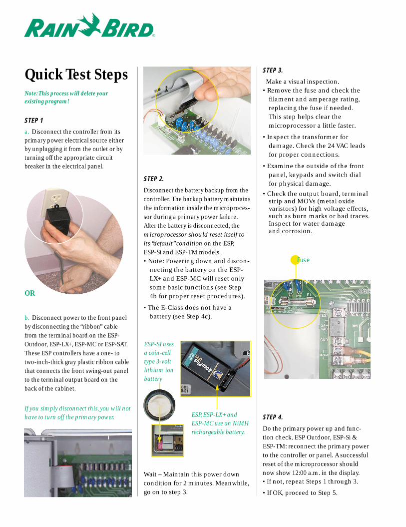
b. Disconnect power to the front panelby disconnecting the “ribbon” cablefrom the terminal board on the ESP-Outdoor, ESP-LX+, ESP-MC or ESP-SAT.These ESP controllers have a one- totwo-inch-thick gray plastic ribbon cablethat connects the front swing-out panelto the terminal output board on theback of the cabinet.
If you simply disconnect this, you will nothave to turn off the primary power.
STEP 2.
Disconnect the battery backup from thecontroller. The backup battery maintainsthe information inside the microproces-sor during a primary power failure. After the battery is disconnected, themicroprocessor should reset itself toits “default” condition on the ESP, ESP-Si and ESP-TM models. • Note: Powering down and discon-
necting the battery on the ESP-LX+ and ESP-MC will reset onlysome basic functions (see Step4b for proper reset procedures).
• The E-Class does not have a battery (see Step 4c).
Wait – Maintain this power downcondition for 2 minutes. Meanwhile,go on to step 3.
STEP 3.
Make a visual inspection.• Remove the fuse and check the
filament and amperage rating,replacing the fuse if needed. This step helps clear the microprocessor a little faster.
• Inspect the transformer for damage. Check the 24 VAC leadsfor proper connections.
• Examine the outside of the frontpanel, keypads and switch dialfor physical damage.
• Check the output board, terminalstrip and MOVs (metal oxidevaristors) for high voltage effects,such as burn marks or bad traces.Inspect for water damage and corrosion.
STEP 4.
Do the primary power up and func-tion check. ESP Outdoor, ESP-Si &ESP-TM: reconnect the primary powerto the controller or panel. A successfulreset of the microprocessor shouldnow show 12:00 a.m. in the display. • If not, repeat Steps 1 through 3.
• If OK, proceed to Step 5.
Fuse
OR
ESP, ESP-LX+ andESP-MC use an NiMHrechargeable battery.
ESP-SI usesa coin-celltype 3-voltlithium ionbattery
Caution! The following additional steps are required to perform the primary power up and function check for ESP-LX+, ESP-MC, ESP-SAT,E-Class & UNIK/Easy Rain!
b. ESP-LX+, ESP-MC, and ESP-SAT
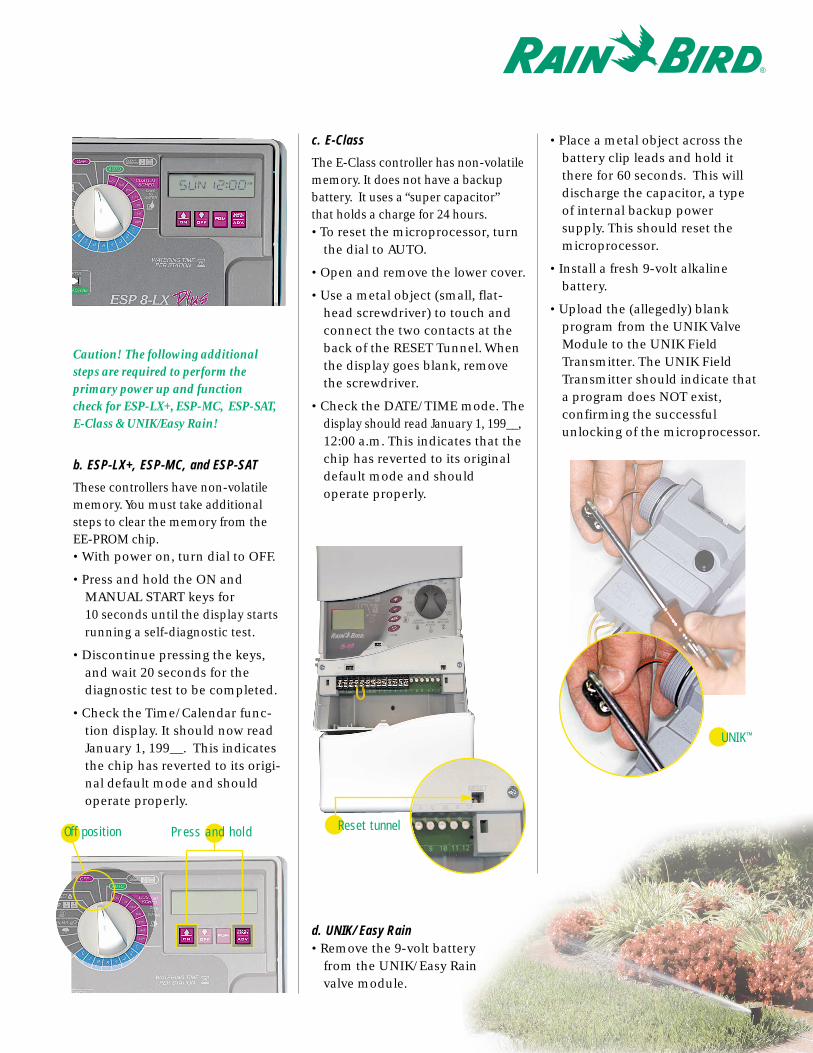
These controllers have non-volatilememory. You must take additional steps to clear the memory from the EE-PROM chip. • With power on, turn dial to OFF.
• Press and hold the ON and MANUAL START keys for 10 seconds until the display startsrunning a self-diagnostic test.
• Discontinue pressing the keys,and wait 20 seconds for the diagnostic test to be completed.
• Check the Time/Calendar func-tion display. It should now readJanuary 1, 199__. This indicatesthe chip has reverted to its origi-nal default mode and shouldoperate properly.
c. E-Class
The E-Class controller has non-volatilememory. It does not have a backup battery. It uses a “super capacitor” that holds a charge for 24 hours. • To reset the microprocessor, turn
the dial to AUTO.
• Open and remove the lower cover.
• Use a metal object (small, flat-head screwdriver) to touch andconnect the two contacts at theback of the RESET Tunnel. Whenthe display goes blank, removethe screwdriver.
• Check the DATE/TIME mode. Thedisplay should read January 1, 199__,12:00 a.m. This indicates that thechip has reverted to its originaldefault mode and should operate properly.
d. UNIK/ Easy Rain• Remove the 9-volt battery
from the UNIK/Easy Rainvalve module.
• Place a metal object across thebattery clip leads and hold itthere for 60 seconds. This willdischarge the capacitor, a type of internal backup power supply. This should reset themicroprocessor.
• Install a fresh 9-volt alkaline battery.
• Upload the (allegedly) blank program from the UNIK ValveModule to the UNIK FieldTransmitter. The UNIK FieldTransmitter should indicate that a program does NOT exist, confirming the successfulunlocking of the microprocessor.
Press and holdOff position Reset tunnel
UNIK™
STEP 5. Load Test• Fire up a station. Connect a sole-
noid to a station on the terminalstrip. Initiate a manual start andcheck solenoid operation.
• Time permitting, try a few more stations.
• If the solenoid doesn’t fire up,double-check the primary powerby measuring the transformeroutput. It should be 24 volts, AC current (26.5 VAC @ 120 VAC primary input).
• If the controller is field-mounted,check the common wire connec-tion. Also check for a rain sensordevice.
Time Out! All these steps can be completed in less that 5 minutes!
At this point, you should have reset themicroprocessor, completed a quickvisual inspection, powered up, andfired one station.
This procedure will eliminate half of all problems associated with today’sgeneration of controllers. Rememberthat faulty field wiring, bad solenoids,high amperage pump starters or poor
primary voltage supply can also cause problems.
Extra Testing Tips
Here are other common problem areaswith controllers and ways that you may be able to identify and easily correct them.
Short Circuits:
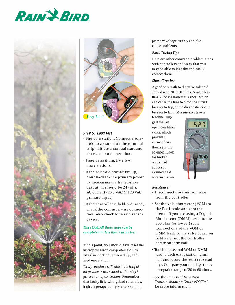
A good wire path to the valve solenoidshould read 20 to 60 ohms. A value lessthan 20 ohms indicates a short, whichcan cause the fuse to blow, the circuitbreaker to trip, or the diagnostic circuitbreaker to fault. Measurements over 60 ohms sug-gest that anopen conditionexists, whichprevents current fromflowing to thesolenoid. Lookfor brokenwires, badsplices orskinned field wire insulation.
Resistance:• Disconnect the common wire
from the controller.
• Set the volt-ohmmeter (VOM) tothe R x 1 scale and zero themeter. If you are using a DigitalMulti-meter (DMM), set it to the200 ohm (or lowest) scale.Connect one of the VOM orDMM leads to the valve commonfield wire (not the controllercommon terminal).
• Touch the second VOM or DMMlead to each of the station termi-nals and record the resistance read-ings. Compare your readings to theacceptable range of 20 to 60 ohms.
• See the Rain Bird Irrigation Trouble-shooting Guide #D37040for more information.
Easy Rain™
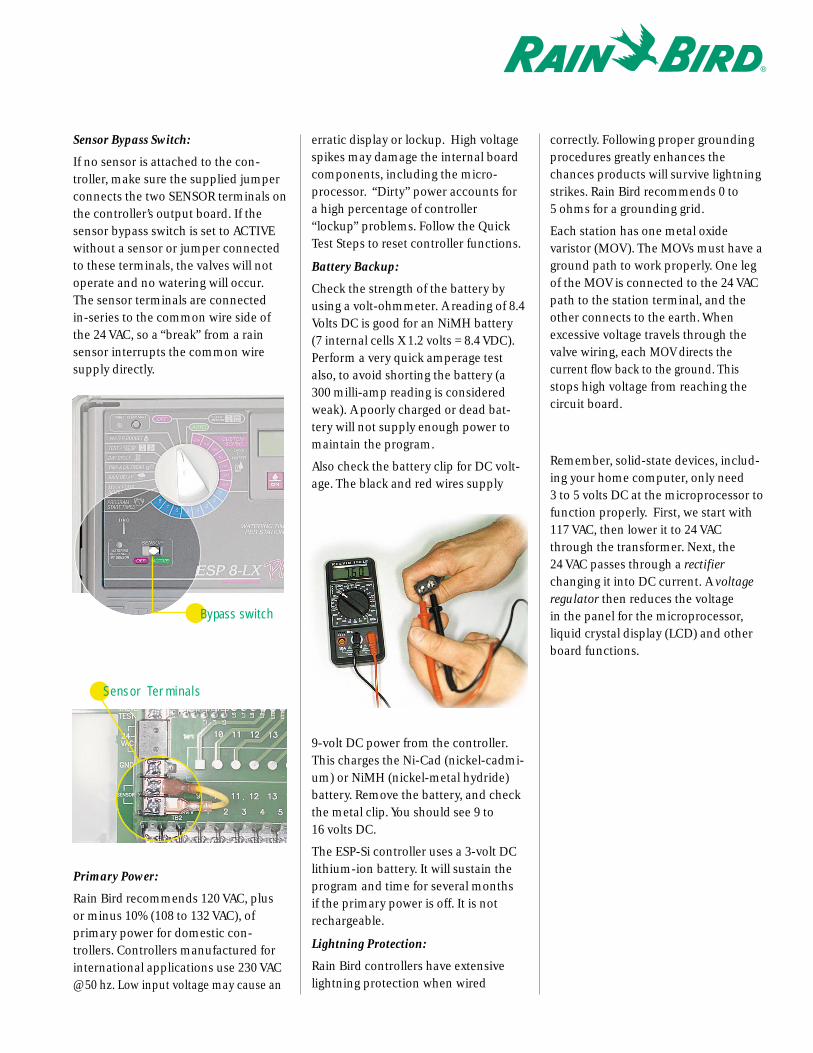
Sensor Bypass Switch:
If no sensor is attached to the con-troller, make sure the supplied jumperconnects the two SENSOR terminals onthe controller’s output board. If thesensor bypass switch is set to ACTIVEwithout a sensor or jumper connectedto these terminals, the valves will notoperate and no watering will occur. The sensor terminals are connected in-series to the common wire side ofthe 24 VAC, so a “break” from a rainsensor interrupts the common wiresupply directly.
Primary Power:
Rain Bird recommends 120 VAC, plusor minus 10% (108 to 132 VAC), of primary power for domestic con-trollers. Controllers manufactured forinternational applications use 230 VAC @ 50 hz. Low input voltage may cause an
erratic display or lockup. High voltagespikes may damage the internal boardcomponents, including the micro-processor. “Dirty” power accounts fora high percentage of controller “lockup” problems. Follow the QuickTest Steps to reset controller functions.
Battery Backup:
Check the strength of the battery byusing a volt-ohmmeter. A reading of 8.4Volts DC is good for an NiMH battery(7 internal cells X 1.2 volts = 8.4 VDC).Perform a very quick amperage testalso, to avoid shorting the battery (a300 milli-amp reading is consideredweak). A poorly charged or dead bat-tery will not supply enough power tomaintain the program.
Also check the battery clip for DC volt-age. The black and red wires supply
9-volt DC power from the controller.This charges the Ni-Cad (nickel-cadmi-um) or NiMH (nickel-metal hydride)battery. Remove the battery, and checkthe metal clip. You should see 9 to 16 volts DC.
The ESP-Si controller uses a 3-volt DClithium-ion battery. It will sustain theprogram and time for several months if the primary power is off. It is notrechargeable.
Lightning Protection:
Rain Bird controllers have extensivelightning protection when wired
correctly. Following proper groundingprocedures greatly enhances thechances products will survive lightningstrikes. Rain Bird recommends 0 to 5 ohms for a grounding grid.
Each station has one metal oxide varistor (MOV). The MOVs must have aground path to work properly. One legof the MOV is connected to the 24 VACpath to the station terminal, and theother connects to the earth. Whenexcessive voltage travels through thevalve wiring, each MOV directs the current flow back to the ground. Thisstops high voltage from reaching thecircuit board.
Remember, solid-state devices, includ-ing your home computer, only need 3 to 5 volts DC at the microprocessor tofunction properly. First, we start with117 VAC, then lower it to 24 VACthrough the transformer. Next, the 24 VAC passes through a rectifierchanging it into DC current. A voltageregulator then reduces the voltage in the panel for the microprocessor,liquid crystal display (LCD) and otherboard functions.
Sensor Terminals
Bypass switch
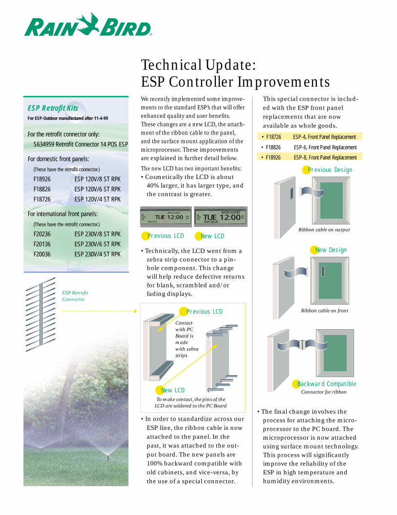
We recently implemented some improve-ments to the standard ESP’s that will offerenhanced quality and user benefits.These changes are a new LCD, the attach-ment of the ribbon cable to the panel,and the surface mount application of themicroprocessor. These improvementsare explained in further detail below.
The new LCD has two important benefits:• Cosmetically the LCD is about
40% larger, it has larger type, andthe contrast is greater.
• Technically, the LCD went from azebra strip connector to a pin-hole component. This changewill help reduce defective returnsfor blank, scrambled and/or fading displays.
• In order to standardize across ourESP line, the ribbon cable is nowattached to the panel. In thepast, it was attached to the out-put board. The new panels are100% backward compatible withold cabinets, and vice-versa, bythe use of a special connector.
This special connector is includ-ed with the ESP front panelreplacements that are now available as whole goods.
• F18726 ESP-4, Front Panel Replacement
• F18826 ESP-6, Front Panel Replacement
• F18926 ESP-8, Front Panel Replacement
• The final change involves theprocess for attaching the micro-processor to the PC board. Themicroprocessor is now attachedusing surface mount technology.This process will significantlyimprove the reliability of the ESP in high temperature andhumidity environments.
ESP Retrofit KitsFor ESP-Outdoor manufactured after 11-4-99
For the retrofit connector only:
S634959 Retrofit Connector 14 POS ESP
For domestic front panels:
(These have the retrofit connector.)
F18926 ESP 120V/8 ST RPK
F18826 ESP 120V/6 ST RPK
F18726 ESP 120V/4 ST RPK
For international front panels:
(These have the retrofit connector.)
F20236 ESP 230V/8 ST RPK
F20136 ESP 230V/6 ST RPK
F20036 ESP 230V/4 ST RPK
Technical Update: ESP Controller Improvements
Previous Design
New Design
Backward CompatibleConnector for ribbon
Ribbon cable on front
Ribbon cable on output
TUE 12:00WATER BUDGET
ABPGMCD
RAIN DELAY
AMPM TUE 12:00
WATER BUDGETABPGMCD
RAIN DELAY
AMPM
New LCDPrevious LCD
ESP RetrofitConnector
Previous LCD
Contactwith PCBoard ismadewith zebrastrips
New LCDTo make contact, the pins of the
LCD are soldered to the PC Board
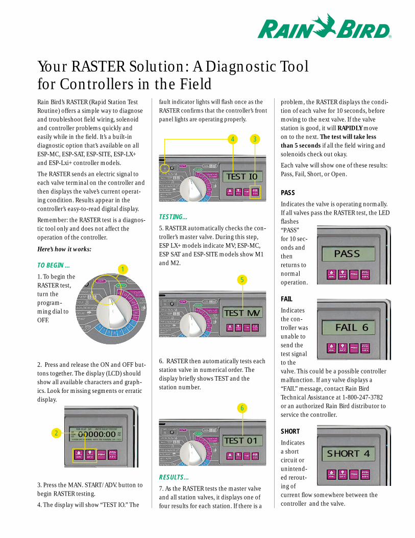
Rain Bird’s RASTER (Rapid Station TestRoutine) offers a simple way to diagnoseand troubleshoot field wiring, solenoidand controller problems quickly and easily while in the field. It’s a built-indiagnostic option that’s available on allESP-MC, ESP-SAT, ESP-SITE, ESP-LX+and ESP-Lxi+ controller models.
The RASTER sends an electric signal toeach valve terminal on the controller andthen displays the valve’s current operat-ing condition. Results appear in the controller’s easy-to-read digital display.
Remember: the RASTER test is a diagnos-tic tool only and does not affect the operation of the controller.
Here’s how it works:
TO BEGIN …
1. To begin theRASTER test,turn theprogram-ming dial toOFF.
2. Press and release the ON and OFF but-tons together. The display (LCD) shouldshow all available characters and graph-ics. Look for missing segments or erraticdisplay.
3. Press the MAN. START/ADV. button tobegin RASTER testing.
4. The display will show “TEST IO.” The
fault indicator lights will flash once as theRASTER confirms that the controller’s frontpanel lights are operating properly.
TESTING…
5. RASTER automatically checks the con-troller’s master valve. During this step,ESP LX+ models indicate MV; ESP-MC,ESP SAT and ESP-SITE models show M1and M2.
6. RASTER then automatically tests eachstation valve in numerical order. The display briefly shows TEST and the station number.
RESULTS…
7. As the RASTER tests the master valveand all station valves, it displays one offour results for each station. If there is a
problem, the RASTER displays the condi-tion of each valve for 10 seconds, beforemoving to the next valve. If the valve station is good, it will RAPIDLY move on to the next. The test will take lessthan 5 seconds if all the field wiring andsolenoids check out okay.
Each valve will show one of these results:Pass, Fail, Short, or Open.
PASS
Indicates the valve is operating normally.If all valves pass the RASTER test, the LEDflashes“PASS” for 10 sec-onds andthenreturns to normaloperation.
FAIL
Indicatesthe con-troller wasunable tosend thetest signalto thevalve. This could be a possible controllermalfunction. If any valve displays a“FAIL” message, contact Rain BirdTechnical Assistance at 1-800-247-3782 or an authorized Rain Bird distributor toservice the controller.
SHORT
Indicates a short circuit orunintend-ed rerout-ing of current flow somewhere between the controller and the valve.
Your RASTER Solution: A Diagnostic Tool for Controllers in the Field
1
2 00000:00RAIN DELAY DAY WATER BUDGET PERCENT
ABPGMCD
STATION DAYS REMAINING WATER TIME REMAINING DAY CYCLE
AMPM
3
TEST I0
4
TEST MV
5
TEST 01
6
PASS
FAIL 6
SHORT 4
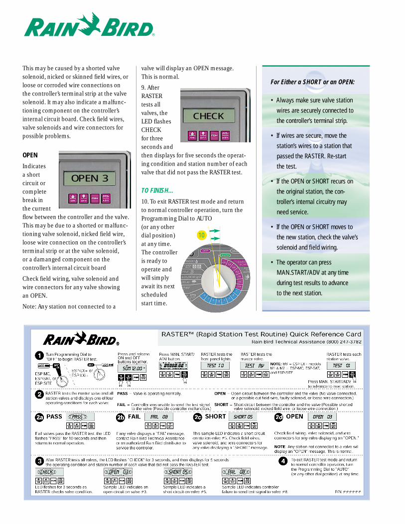
This may be caused by a shorted valvesolenoid, nicked or skinned field wires, orloose or corroded wire connections onthe controller’s terminal strip at the valvesolenoid. It may also indicate a malfunc-tioning component on the controller’sinternal circuit board. Check field wires,valve solenoids and wire connectors forpossible problems.
OPEN
Indicates a short circuit orcompletebreak inthe currentflow between the controller and the valve.This may be due to a shorted or malfunc-tioning valve solenoid, nicked field wire,loose wire connection on the controller’sterminal strip or at the valve solenoid, or a damanged component on the controller’s internal circuit board
Check field wiring, valve solenoid andwire connectors for any valve showing an OPEN.
Note: Any station not connected to a
valve will display an OPEN message. This is normal.
9. AfterRASTERtests allvalves, theLED flashesCHECK for threeseconds andthen displays for five seconds the operat-ing condition and station number of eachvalve that did not pass the RASTER test.
TO FINISH…
10. To exit RASTER test mode and return to normal controller operation, turn theProgramming Dial to AUTO (or any otherdial position)at any time.The controlleris ready tooperate andwill simplyawait its nextscheduledstart time.
OPEN 3
For Either a SHORT or an OPEN:
• Always make sure valve station
wires are securely connected to
the controller’s terminal strip.
• If wires are secure, move the
station’s wires to a station that
passed the RASTER. Re-start
the test.
• If the OPEN or SHORT recurs on
the original station, the con-
troller’s internal circuitry may
need service.
• If the OPEN or SHORT moves to
the new station, check the valve’s
solenoid and field wiring.
• The operator can press
MAN.START/ADV at any time
during test results to advance
to the next station.
10
CHECK