field survey guidelines and baseplan requirements for survey … · 2018-07-20 · introduction ....
TRANSCRIPT

Field Survey Guidelines
and
Baseplan Requirements
for
Survey and Design
Consultants
Version 2.2
October 2014

2
Introduction Survey and design consultants performing survey work on projects funded,
managed, or constructed by the Massachusetts Department of Transportation
(MassDOT) shall conduct field surveys and prepare baseplans in accordance with
these guidelines as a supplement to the following:
Massachusetts Highway Department Project Development & Design Guide, 2006
Massachusetts Highway Department Survey Manual, Metric Edition, 1996 MassDOT LRFD Bridge Manual Design Guidelines MassDOT Highway Division CAD Standards Manual
MassDOT requires that all survey data be collected electronically for the
preparation of baseplans. A baseplan, also known as an “existing conditions”
plan, is a graphical representation of the preliminary “as is” survey data.
The consultant must be prequalified in the “S2. Total Station AutoCAD Base Plan
Services” category by the MassDOT Architects and Engineers Review Board.
The consultant firm’s Professional Land Surveyor registered in Massachusetts to
be in responsible charge of the survey services provided on a MassDOT project
must be available to meet and discuss, if necessary, the baseplan during both
the design and construction phases of the project. Contact information for the
PLS must be provided.
All land surveys for MassDOT shall adhere to all current, appropriate and
applicable laws, rules and regulations, including but not limited to, the Code of
Massachusetts Regulations, General Laws, and the Land Court Manual of
Instructions for the Survey of Lands and Preparation of Plans.

3
Research The survey or design consultant shall obtain research materials pertinent to the project
location. Copies of the following shall be obtained and submitted in suitable electronic
format (PDF, TIFF, JPG, XPS, etc.) on the CD/DVD. Documents deemed illegible will
be returned and clean, legible copies will be requested.
1. Assessor Information for Abutters
a. Assessor’s Maps b. Assessor’s Parcel ID/MBLU c. Current owner name
d. Operative deed and plan from the Registry of Deeds
i. Back deeds and plans as necessary.
2. Roadway layout information, plan and instrument, for State, County and local
traveled ways.
3. Other plans from Registry of Deeds and local government offices (e.g.
City/Town/State Engineering Dept.)
4. Land Court information (if applicable).
a. Certificate, plan and encumbrances.
5. Utilities
a. List of companies with contact information.
b. Scanned plans, GIS files, dwg/dxf files, etc.
6. Floodplain Information (if applicable)
a. FIRMette with all applicable panel and date information.
The research package shall include any and all documents obtained from MassDOT.
(e.g. SHLO plans obtained from District Survey Supervisor, the Survey Request form,
etc.)
Survey Field Books and Notes The consultant shall obtain a MassDOT field book from either the respective District
Survey Office or the Boston Survey Office prior to commencing work. All field notes,
field calculations, and sketches are to be entered into this book. Entries shall be in
pencil and written in neat, legible print. Do not erase any errors entered in the field
book. Errors shall be crossed out with a single horizontal line.

4
The field book shall:
1. Be indexed at the front of the book. The index shall contain all projects found in
the book and a brief description of work that is contained. Cross references shall
be listed in the index under the appropriate MassDOT project number.
2. Have a heading at the start of each day containing the MassDOT project number,
Consultant project number, job title, description, road name, names of crew
members, weather conditions, date, make and model of instrument, and data
collector file name. Succeeding pages for that day shall have the MassDOT
project number, crew initials, date, and weather changes.
3. Contain general traverse sketches showing the approximate relationship of
traverse points and monuments located.
4. Contain tie sketches for each point in the main traverse showing swing ties to
three (3) well described, semi-permanent objects.
5. Contain additional sketches as necessary for successful translation of
information from field to plan.
6. Show the instrument setup and backsight information for traverse and
topography. The setup orientation shall be identified by point numbers. The
height of instrument and backsight shall be recorded. Horizontal and vertical
measurements between the setup shall be recorded. Any change in instrument
height or backsight height shall have a new full setup recorded in the field book.
All points located from the setup shall be noted. Each traverse point and
monument shall be individually noted and fully described. Detail locations and
topography may be recorded as point ranges. Any point requiring a description
greater than the data collector allows or requiring a correction or edit shall be
recorded in the book with point number, rod height, description/code and
applicable notes.
7. Contain level run data for temporary benchmarks (TBM’s) set throughout the
project. Each project shall have a minimum of two TBM’s set. Longer highway
projects shall have TBM’s set every 1000’ or at elevation differences greater than
50’ as required by the Survey Manual. All benchmarks found and TBM’s set
shall be well described. MassDOT and NGS benchmarks shall have their point
ID and designation/station in the description.
The consultant shall deliver the field book to the office from which it was obtained at the
end of the project. Copies/scans of the field book shall be provided with the final
baseplan submission.

5
Traverse and Monuments The MassDOT Survey Section shall set control and furnish values and tie sketches to
the consultant for all MassDOT survey projects. Should control not be provided prior to
commencement of survey please contact the respective District Survey Supervisor
and/or the MassDOT Project Manager.
1. Traverse/control points shall be based on the North American Datum of 1983
(NAD83) and the Massachusetts State Plane Coordinate System.
2. Traverse/control points, topography and benchmarks shall be based on the North American Vertical Datum of 1988 (NAVD88).
3. The traverse/control points shall have reference to the full datum tag, reference
to the vertical datum, and GEOID model noted on the face of the plan.
4. All traverse points shall be labeled on the face of the plan with point number,
northing, easting, elevation, and description.
5. All traverse points shall be field coded in the manner MTRV PK, MTRV MAG,
MTRV REBAR, MTRV PK GPS BOS1, etc…
a. This ensures the proper symbol and label appear on the plan through the
description key.
b. Please use MassDOT specified abbreviations (not field codes) for descriptors following the MTRV code.
6. Traverse shall be connected as run in the field and annotated with bearing and
distance. Several traverse points shall be tied perpendicularly, with station and
offset, to the baseline or radially, with bearing and distance, to sideline angle
points of the roadway layout. The preference is for ties to the baseline. For
plotting purposes turn off/freeze EX-SV-TRAV-LINE and EX-SV-TRAV-TEXT.
7. All monuments found and located shall be fully described by type, material, mark
and condition. If a monument is held for position or rotation for property line
determination it shall be noted on the face of the plan.
8. Monuments shall be coded as follows: a. MMHB is for Massachusetts Highway Bounds only.
b. MMON is for all other bounds.
c. MTBD is for town line corner bounds. d. MRST is for town line road stone monuments, which indicate the
approximate location of the town line.
e. MIPE, MMAG, MPKN, MREB, MRRS, MSTN, MXCT are codes for non-
traverse points located for property and/or baseline location.

6
9. Monuments found to be outside of standard errors shall have ties to the
theoretical corner placed on the face of the plan. Two perpendicular distances or
a single bearing and distance are acceptable.
All traverse analysis/adjustment files, both raw and adjusted, shall be included with the
final baseplan submission. These include but are not limited to AutoCAD generated
text files with .lsi, .lso, .trv file extensions. If using a separate software for traverse
analysis/adjustment, such as STAR*NET, please include all generated files such as
.dat, .lst, .pts, etc.
General Field Survey Consultants are required to use MassDOT coding for all types of field location. The
consultant shall obtain the latest MassDOT Description Key Code Set from MassDOT
Highway Division CAD Standards. The description keys are provided in two formats,
one categorical and one alphabetical to assist in field and office use.
1. Only data collection devices having alphanumeric capability to record comment,
descriptions and other relevant project information are to be used. Collection of
field survey data shall be comprehensive. All ground features pertinent to the
required end product shall be collected as part of the field effort.
2. Points shall be systematically collected in the field. Each point must be
described by a MassDOT description code as found in the Description Key Code
Set.
3. Any point requiring a description greater than the data collector allows or requiring
a correction or edit shall be recorded in the field book with point number, rod height,
description/code and applicable notes.
4. The first and last shot from each setup shall be a backsight check coded “MFLY”. 5. MassDOT requires the use of the line work feature of data collectors. The
MassDOT figure prefix database can be found within the MassDOT Highway Division CAD Standards Manual.
Two copies of data collector files are to be included in the final baseplan submission,
one raw and one edited. The files may include but are not limited to .raw, .rw5, .fbk,
.sdr, .crd, cr5, etc.. All points are to be exported to a PNEZD comma delimited ascii .txt
or .csv file.
Survey for Bridges Please adhere to the MassDOT LRFD Bridge Manual Design Guidelines.

7
Drafting Requirements for Survey Baseplans All survey baseplans shall adhere to the latest version of the CAD Standards Manual.
All survey baseplans shall be created in AutoCAD Civil 3D using the version supported
by MassDOT. All new projects must use the latest version of the drawing template and
support files as found on the CAD Standards website.
Please check the website frequently as updates are released on an as needed basis. All MassDOT layers, linetypes, text styles, point styles and point label styles to be
used are found in the template and supporting files. Additional layers may be created
as necessary. The created items shall follow convention set out by the MassDOT
CAD Standards Manual. A report shall be included in the final deliverable with each
created item fully described and the reason for creation.
Standard Presentation
All baseplans shall be drafted to be plotted on the survey title and plan sheets found in
the SURVEY_SHEETS.dwg. No work shall be done inside the
SURVEY_SHEETS.dwg. Rather, the title and plan layouts found in
SURVEY_SHEETS.dwg shall be inserted into a drawing created from the MassDOT
template.
All baseplans shall have:
1. A title block on each sheet. (Provided in the SURVEY_SHEETS.dwg)
2. A north arrow, with datum specified, on each sheet. (Provided in the SURVEY_SHEETS.dwg and GENERAL_SYMBOLS.dwg)
3. A text and graphic bar scale, on each sheet. (Provided in the
SURVEY_SHEETS.dwg and GENERAL_SYMBOLS.dwg)
4. A standard list of abbreviations specific to MassDOT. (Provided on the title
sheet of SURVEY_SHEETS.dwg)
5. A legend. (Provided on the title sheet of SURVEY_SHEETS.dwg)
6. A list of plan references.
7. A PLS stamp and signature on every sheet per the Advisory Ruling from The
Board of Registration of Professional Engineers and Professional Land
Surveyors.
8
Units and Data
All baseplans shall be in US Survey Feet. Coordinate values shall be shown to four (4)
decimal places. Linear values and elevations shall be shown to two (2) decimal places.
All azimuths and bearings shall be reported to the second.
The horizontal coordinate system shall be Massachusetts State Plane, North American
Datum of 1983 (NAD 83). The control points provided by MassDOT Survey Section
shall be held fixed. Layout plans shall be rotated to the provided control and
monuments located from the traverse network based on this control. Appropriate notes
shall be placed on the face of the plan stating:
The coordinate system with full datum tag, e.g., Massachusetts State Plane,
Mainland Zone, NAD 83(2011) epoch 2010.00
Who set/provided the control and the method used.
The control points that were established/provided.
The average scale factor for the project.
The rotation from the layout plan bearing system to the baseplan. The vertical datum shall be the North American Vertical Datum of 1988 (NAVD 88). A
note shall be placed on the face of the plan stating the vertical datum and the GEOID if
established by GPS. When the vertical control is solely established by conventional
leveling methods the benchmarks MassDOT ID, NGS ID, Station Name and data shall
be noted on the face of the plan.
All control set and established by the MassDOT Survey Section shall be furnished to the
Survey Consultant with all pertinent data for the above required horizontal and vertical
notes. The consultant may request a change in the horizontal and/or vertical data from
the MassDOT Project Manager and the District Survey Supervisor. The appropriate
notes must be placed on the face of the plan regarding the horizontal and vertical data
used.
Scale and Paper Size
Survey baseplans shall be drafted at 20 scale and plotted on Architectural D size paper
(24” x 36”). Plotting for bridge details, cross-sections, and profiles shall follow the
requirements of the manuals and guides referred to in the Introduction of this document.
The consultant may request a change in scale and/or paper size for specific projects
from the MassDOT Project Manager and the District Survey Supervisor.

9
General Layering Conventions for Lines, Blocks, Points and Text Please refer to the MassDOT Highway Division CAD Standards Manual. Survey baseplans primarily use the EX-SV- layers in the MassDOT AutoCAD Civil 3D
template. The layer EX-SV-TR-FEAT is a survey layer. The layer EX-TR-FEAT is a
traffic layer. Survey baseplans will also use EX-EV-, EX-GT-, EX-LO-, EX-UT-, RD-
UT-, layers as appropriate.
Many objects in the template also have a corresponding text layer. This text layer is
typically included for plotting style changes and linetype changes should a leader be
necessary. Text for labels and remarks involving objects on these layers go on this
specified text layer. The label “12” PLASTIC GAS – NSTAR” shall be placed on the
EX/RD-UT-GAS-TEXT layer. Text for labels and remarks for objects that do not have
a corresponding text layer shall be placed on the same layer as the object. The label
“BIT. DRIVE” shall be placed on EX-SV-EOP. The label “TREELINE” shall be placed
on EX-SV-VEGE. Other miscellaneous text, such as WCR (wheelchair ramp), shall be
placed on the EX-SV-TEXT layer.
Utility Layering Conventions
MassDOT requires utilities to be shown on baseplans. Utility contact information can
be found on the MassDOT Utility Section Website.
All information obtained from utility companies affecting the project area shall be
submitted in the research package.
MassDOT makes use of three categories of utilities to be shown on baseplans. These
are existing, proposed and record and are defined as follows.
EXISTING: (Layer convention EX-UT-)
Utility objects that have been observed and field located shall be placed on the
appropriate EX-UT- layer. Only field located utilities and their descriptions are to be
placed on EX-UT- layers.
RECORD: (Layer convention RD-UT-)
Utility objects that have not been observed and/or physically located shall be placed
on the appropriate RD-UT- layer. Utility locations that are derived from record
drawings, from Dig Safe markings, and from other evidence, such as pavement
patches, are to be placed on the RD-UT- layers.
PROPOSED: (Layer convention: PR-UT-)
Utility objects that are being designed for future installation shall be placed on the
appropriate PR-UT- layer.

10
Contour Surfaces
Contour intervals indicate the accuracy of a baseplan. The standard contour intervals
for baseplans are 1’ minor and 5’ major. Standard surface styles have been created in
the MassDOT template. These surface styles shall be used and the surface shall be an
AutoCAD Civil 3D Object and shall exist wholly in the AutoCAD Civil 3D baseplan .dwg
file. Surface references to files on a computer and/or to XML files are not acceptable.
Large surfaces which generate .mms files shall have the .mms file included in the
deliverable. Additional styles exist in the template for 1’ and 5’ intervals for
photogrammetry/remote sensing and 2’ and 10’ intervals for ground survey and
photogrammetry/remote sensing.
It is standard practice for photogrammetry/remote sensing data to be supplemented with
ground survey. When ground survey is merely supplemental for obscured areas, check
shots, wetlands and utility locations, a single seamless surface shall be maintained on
the appropriate PHOTO surface style. When ground survey is required to be performed
in detail these areas shall be created in a separate standard surface.
Baselines, Sidelines, Property Lines, and their Text All baselines shall be AutoCAD Civil 3D Object alignments with labels. Styles have
been created for each type of baseline: state highway layout, county layout, town layout,
etc. The base Civil 3D object layer for all alignments is OB-BASELINE. The alignment
style used to create the baseline will automatically place the alignment on the
appropriate EX-SV-BL- layer and pattern the line appropriately. The base Civil 3D
object layer for alignment text is OB-BASELINE-TEXT. Selecting the appropriate
alignment label set will automatically create stationing and ticks in the required
MassDOT formatting, placing the text and symbols on EX-SV-BL-GEOM. All baselines
shall have their location determined unless otherwise stated in the survey request. All
baselines shall be labeled with date, layout number, and description as necessary (e.g.
1944 SHLO 2167 – AUX. BASELINE “D”). The label layer is EX-SV-BL-TEXT. Text
style is DOT-E.
All sidelines shall have their location determined unless otherwise stated in the survey
request. Sidelines shall be placed on the appropriate EX-LO- layer. All sidelines shall be
labeled with date and layout number (e.g. LOCATION LINE OF 1944 SHLO 2167). The
layer is EX-LO-TEXT. Text style is DOT-E.
State Lines, County Lines, Town Lines, Abutter Property Lines and Easement Lines,
shall have their location determined on a by project basis. Lines not determined shall
be labeled approximate. These lines shall be placed on the appropriate EX-SV-LN-
layer. The text for these lines shall be placed on the EX-SV-LN-TEXT layer.

11
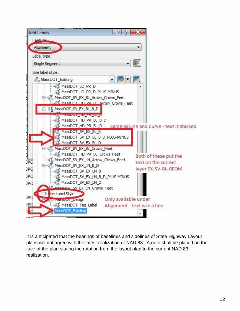
All baselines and sidelines shall be annotated with their geometry using the appropriate
MassDOT annotation label style. State Lines, County Lines, Town Lines, Abutter Property
Lines and Easement Lines that have been determined shall be annotated using the appropriate
MassDOT annotation label style. The appropriate use of the MassDOT annotation label styles
will create the geometry text for lines and arcs on the correct layer, using the correct text style,
at the proper text height for the drawing scale. The layers for the geometry text are EX-LO-
GEOM, EX-SV-BL-GEOM, and EX-SV-LN- GEOM. The base Civil 3D object layers that these
annotations are created on are OB- BASELINE-TEXT and OB-TEXT. Text style is DOT-E.
12
It is anticipated that the bearings of baselines and sidelines of State Highway Layout
plans will not agree with the latest realization of NAD 83. A note shall be placed on the
face of the plan stating the rotation from the layout plan to the current NAD 83
realization.

13
Additionally, baselines shall be labeled with an equation station at each baseline-
baseline intersection, merge/diverge, change in layout number, and station jump. The
image below indicates the annotation label style to be used. This label style is for two
baselines only, manual editing of the text is required if there are more than two
baselines.
Roadway Text
All roadway names shall be labeled with State Highway/County Layout or Public/Private
and Width. The layout number need not be included as the baseline and sidelines will
have this information and layout numbers may change at odd intervals over the length
of a project.
STATE HIGHWAY NAME (STATE HIGHWAY LAYOUT)
OR
LOCAL ROADWAY NAME (1967 TOWN LAYOUT – VARIABLE WIDTH)
The layer is EX-LO-TEXT. The text style is DOT-STREET. The descriptive text
information may be reduced in size.

14
Abutter Text
All abutter properties shall be labeled with street number and street name, owner name,
book and page, and assessor ID/MBLU. The label shall be placed on the EX-SV-LN-
TEXT layer. The text is style DOT-E.

15
Final Deliverable The final deliverable shall consist of a CD/DVD and a baseplan plotted on mylar. The
submission shall be submitted to the Survey Engineer of the MassDOT Survey Section
in Boston. Additional copies shall be submitted to the District Survey Supervisor as
requested.
The CD/DVD shall contain all data gathered by the company for the project and a pdf of
the signed and stamped baseplan. The data shall be placed in the appropriate folders
adhering to the folder structure as laid out in the MassDOT Highway Division CAD
Standards Manual.
The mylar baseplan shall be stamped and signed on each individual page per the Advisory Ruling by the Division of Professional Licensure.