field sampling plan for cercla site anl-04 at the ... sampling plan for cercla site anl-04 at the...
TRANSCRIPT
DOE/ID-11552 Revision 0
Field Sampling Plan for CERCLA Site ANL-04 at the Materials and Fuels Complex
October 2016
Valerie M. Kimbro


DOE/ID-11552
Revision 0 Project No. 23368
Field Sampling Plan for CERCLA Site ANL-04 at the Materials and Fuels Complex
Valerie M. Kimbro
Edited by Michael J. Ingram
October 2016
Prepared for the U.S. Department of Energy
DOE Idaho Operations Office


iii
ABSTRACT
This Field Sampling Plan describes soil sampling that will be conducted under the Comprehensive Environmental Response, Compensation, and Liability Act (CERCLA) to characterize Site ANL-04 at the Materials and Fuels Complex on the Idaho National Laboratory Site. ANL-04 consists of the former sanitary sewage lagoons and was transferred from Operable Unit (OU) 9-04 to OU 10-08 to be addressed when the lagoons were no longer in service. The OU 10-08 Record of Decision stated that ANL-04 was to be resampled and risk recalculated; if the site poses an unacceptable risk, the OU 9-04 contingent remedy of removal and disposal would be implemented. A preliminary human health risk evaluation shows no unacceptable risk to human health or the environment. However, further characterization sampling under CERCLA is necessary to ensure ANL-04 qualifies for unlimited use and unrestricted exposure. In addition, samples may be collected under this Field Sampling Plan to satisfy closure requirements under Idaho wastewater rules and Environmental Protection Agency standards for beneficial use or disposal of biosolids.

iv

v
CONTENTS
ABSTRACT ................................................................................................................................................. iii
ACRONYMS .............................................................................................................................................. vii
1. INTRODUCTION .............................................................................................................................. 1
1.1 Background ........................................................................................................................... 1
1.2 Site Description ..................................................................................................................... 3
1.3 Sampling Scope and Assumptions ........................................................................................ 6
2. DATA QUALITY OBJECTIVES ...................................................................................................... 8
3. SAMPLE COLLECTION ................................................................................................................ 11
3.1 Sample Design and Procedure for CERCLA ...................................................................... 11
3.1.1 Study Area Boundary ........................................................................................ 11
3.1.2 Sampling Procedure .......................................................................................... 11
3.2 Sample Design and Procedure for Part 503 Biosolids Rule ................................................ 13
3.2.1 Study Area Boundary ........................................................................................ 13
3.2.2 Sampling Procedure .......................................................................................... 14
3.3 Decontamination Procedure ................................................................................................ 14
3.4 Sampling and Analysis Requirement .................................................................................. 14
3.5 Sampling Equipment ........................................................................................................... 19
3.6 Sampling Documentation and Management ........................................................................ 19
3.6.1 Sample Logbook ............................................................................................... 20
3.7 Sample Designation and Labeling ....................................................................................... 20
3.8 Chain of Custody ................................................................................................................. 20
3.9 Sample Transport................................................................................................................. 21
3.10 Waste Management ............................................................................................................. 21
3.10.1 Waste Minimization .......................................................................................... 21
4. SAMPLE ANALYSIS ...................................................................................................................... 22
4.1 Analytical Methods ............................................................................................................. 22
4.2 Instrumentation Calibration Procedure ................................................................................ 22
4.3 Laboratory Records ............................................................................................................. 22
5. DATA MANAGEMENT AND DOCUMENT CONTROL ............................................................ 23
5.1 Data Reporting .................................................................................................................... 23
5.2 Data Validation .................................................................................................................... 23
5.3 Data Quality Assessment ..................................................................................................... 23

vi
6. HEALTH AND SAFETY REQUIREMENTS ................................................................................. 25
7. PROJECT ORGANIZATION AND RESPONSIBILITIES ............................................................ 26
7.1 Technical Lead .................................................................................................................... 26
7.2 Waste Generator Services Waste Technical Specialist ....................................................... 26
7.3 Sample and Analysis Management ..................................................................................... 26
8. REFERENCES ................................................................................................................................. 27
FIGURES
1. CERCLA Site ANL-04 at the Materials and Fuels Complex ............................................................. 2
2. ANL-04 sewage lagoons ..................................................................................................................... 4
3. ANL-04 Lagoon #1 (top) and Lagoon #2 (bottom) ............................................................................ 5
4. ANL-04 Lagoon #3 ............................................................................................................................. 6
5. ANL-04 sample grids and random sample locations ........................................................................ 12
TABLES
1. Data quality objectives for ANL-04 sampling .................................................................................... 8
2. Composite sampling requirements for the ANL-04 lagoons ............................................................. 13
3. Grab sampling requirements for the ANL-04 lagoons ...................................................................... 13
4. Summary of sampling information for the ANL-04 study area ........................................................ 15

vii
ACRONYMS
CERCLA Comprehensive Environmental Response, Compensation, and Liability Act
COC contaminant of concern
DOE Department of Energy
DQO data quality objective
EPA Environmental Protection Agency
FFA/CO Federal Facility Agreement and Consent Order
FSP field sampling plan
INL Idaho National Laboratory
MFC Materials and Fuels Complex
OU operable unit
PSQ principal study question
QAPjP Quality Assurance Project Plan
QC quality control
ROD Record of Decision
SAM Sample and Analysis Management
WGS Waste Generator Services

viii

1
Field Sampling Plan for CERCLA Site ANL-04 at the Materials and Fuels Complex
1. INTRODUCTION ANL-04 is a Comprehensive Environmental Response, Compensation, and Liability Act
(CERCLA) (42 USC § 9601 et seq.) site consisting of the former sanitary sewage lagoons at the Materials and Fuels Complex (MFC), located in the southeast part of the Idaho National Laboratory (INL) Site (see Figure 1). The site was included in the Federal Facility Agreement and Consent Order (FFA/CO) Action Plan (DOE-ID 1991) and was to be addressed by the Operable Unit (OU) 9-04 Record of Decision (ROD) (DOE-CH 1998), as modified by the Explanation of Significant Differences (DOE-CH 2004). However, in 2005, the U.S. Department of Energy Idaho Operations Office, the U.S. Environmental Protection Agency (EPA), and the Idaho Department of Environmental Quality (collectively known as the Agencies) transferred ANL-04 to OU 10-08. The OU 10-08 ROD (DOE-ID 2009) stated that when the ANL-04 lagoons are closed, resampled, and risks recalculated, then the contingent remedy of removal and disposal from the OU 9-04 ROD will be implemented if the site poses an unacceptable risk. If there is no unacceptable risk, no action will be taken under CERCLA.
The purpose of this Field Sampling Plan (FSP) is to describe sampling to characterize ANL-04. Data collected under this plan will be used to evaluate risk and cleanup options in accordance with the OU 9-04 ROD (DOE-CH 1998) as incorporated into the OU 10-08 ROD (DOE-ID 2009) and Work Plan (DOE-ID 2010). In addition, samples may be collected under this FSP to satisfy closure requirements under Idaho wastewater rules and EPA standards for beneficial use or disposal of biosolids under the Part 503 Biosolids Rule (40 CFR 503). Wastewater closure requirements do not fall under authority of the FFA/CO, and decisions will be managed separately from CERCLA by the appropriate regulating entities. This FSP may be implemented as one sampling effort or in a phased approach and may exclude microbiology analysis for Part 503 Biosolids Rule requirements, depending on results from the CERCLA risk assessment.a
1.1 Background Originally established in 1949, the INL Site is a U.S. Department of Energy (DOE) -managed
reservation that historically has been devoted to energy research and related activities. MFC—one of nine major facilities on the INL Site—was established in the mid-1950s to support advanced nuclear reactor and nuclear fuel design and testing. In 1989, EPA added the INL Site to the National Priorities List (54 FR § 48184) under CERCLA. The FFA/CO and its attached Action Plan (DOE-ID 1991) were negotiated and signed by the Agencies to establish a procedural framework for implementing CERCLA. The FFA/CO subdivided the INL Site into 10 waste area groups. MFC was assigned to Waste Area Group 9, which comprised multiple OUs to address various release sites. The comprehensive OU 9-04 ROD (DOE-CH 1998) incorporated all MFC OUs and embodies the final selected remedy for MFC.
CERCLA remedial actions at MFC were completed between 1999 and 2005 (Portage 2005) and remaining ongoing response actions are institutional controls. To facilitate close-out of Waste Area Group 9, the Agencies transferred the ANL-04 sewage lagoons to OU 10-08 for implementation of the OU 9-04 remedy when the lagoons were no longer in service. The ANL-04 sewage lagoons were removed from service after a new sewage lagoon system was installed in 2012.
a. There are a limited number of microbiology laboratories certified by the Nuclear Regulatory Commission and none that
currently are on the Idaho Cleanup Project Qualified Suppliers List. The project team will continue to explore options to identify a laboratory, either on- or off-Site, that can perform microbiology analysis for Part 503 Biosolids Rule requirements.

2
Figure 1. CERCLA Site ANL-04 at the Materials and Fuels Complex.

3
1.2 Site Description The ANL-04 sewage lagoons are located north of MFC (see Figure 1). ANL-04 comprises three
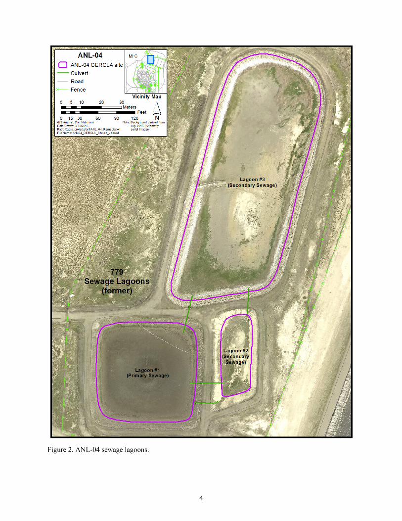
evaporative lagoons that treated sludge by natural attenuation. Lagoon #1 (primary sewage lagoon) and Lagoon #2 (secondary sewage lagoon) were constructed in 1965 and 1970, respectively, and an additional secondary sewage lagoon (Lagoon #3) was built in 1974. The three lagoons cover approximately 2 acres, and dimensions of each lagoon are 150 × 150 × 7 ft (Lagoon #1), 50 × 100 × 7 ft (Lagoon #2), and 125 × 400 × 7 ft (Lagoon #3) (see Figure 2). The bottom of Lagoons #1 and #2 is sealed with a layer of bentonite 1/8 to 1/4 in. thick, and Lagoon #3 has a 2-in.ithick bentonite layer. There is approximately 10 to 24 in. of biosolids in Lagoon #1, 6 in. in Lagoon #2, and 12 in. in Lagoon #3.b
The lagoons received sanitary wastewater originating at MFC that was discharged from rest rooms, change facilities, drinking fountains, and cafeteria. Wastewater was sent to the center of Lagoon #1, which served as a settling lagoon for wastewater constituents, and overflow went to Lagoon #2 for evaporation and to the surrounding land when there was insufficient capacity (Cahn 2015). Then, beginning in 1974 after Lagoon #3 was installed to accommodate the growing population at the facility, overflow from Lagoon #2 was sent to Lagoon #3.
After construction of Lagoon #3, a leak was discovered in the northeast corner of the lagoon over a fissure in the underlying basalt. Before repairs could be made, over a million gallons of wastewater escaped Lagoon #3. The leak was repaired by installing a Hypalon liner; subsequently, the lagoon passed seepage tests and it was determined groundwater was not impacted by the release (DOE-CH 1998).
Later, because of concerns for seepage from Lagoon #2, its use was discontinued in 1997 after repairs were unsuccessful. Overflow between lagoons was redesigned where an overflow pipe was added to connect Lagoon #1 directly to Lagoon #3 and Lagoon #2 only was used for emergency overflow (Cahn 2015).
There are no known releases to the ANL-04 sewage lagoon system except for facility wastewater and photo processing solution. Between 1975 and 1981, photo processing solutions from the fuel assembly and storage building were discharged to the lagoons, releasing silver to the sewage treatment system. Silver was eliminated as a contaminant of concern (COC) after the Track 1 investigation because estimated silver concentrations did not exceed risk-based levels, and no other sources of potential contamination were identified (ANL 1994). However, to address a data gap during preliminary CERCLA investigations, sludge samples were collected in 1994 from Lagoons #1 and #3 and analyzed for metals and radionuclides. The lagoons required a response action under OU 9-04 because mercury concentrations presented a risk to ecological receptors (DOE-CH 1998). The OU 9-04 response action (removal and disposal) was deferred and transferred to OU 10-08 pending closure of the lagoons.
In 2010, DOE Office of Nuclear Energy approved installing a new sewage lagoon system to replace the ANL-04 lagoons, which were at the end of their design life and at capacity. The MFC Evaporative Sewage Lagoons, built adjacent to the ANL-04 lagoons, became operational in 2012 and ANL-04 sewage lagoons were removed from service. Figures 3 and 4 show the lagoons in 2016.
After the sewage lagoons were taken out of service, samples again were collected from Lagoon #1 and Lagoon #3 and analyzed for metals and radionuclides. A preliminary risk assessment concluded ANL-04 does not pose an unacceptable risk to human health or the environment (Cahn 2015); however, the Agencies required additional characterization under CERCLA to ensure the site qualifies for unrestricted use and unlimited exposure and the Idaho Department of Environmental Quality suggested samples also be collected to satisfy closure requirements under Idaho wastewater rules (IDAPA 58.01.16) and Part 503 Biosolids Rule for beneficial use or disposal of biosolids. b. The depth of biosolids in Lagoon #2 is estimated from process knowledge. The exact depth of biosolids in the lagoon is
unknown.
4
Figure 2. ANL-04 sewage lagoons.

5
Figure 3. ANL-04 Lagoon #1 (top) and Lagoon #2 (bottom).

6
Figure 4. ANL-04 Lagoon #3.
Metals are CERCLA COCs because they typically are present in varying amounts and can accumulate in sludge over time, presenting an unacceptable risk to human health and ecological receptors. Though historical records indicate radionuclides were not discharged to the system and are not COCs, samples collected under this FSP will be analyzed for radionuclides to confirm concentrations do not pose an unacceptable risk to human health or the environment. Analytical requirements for beneficial use or disposal of biosolids for Idaho wastewater rules and EPA standards include metals, nutritive value, and pathogens. CERCLA and Part 503 Biosolids COCs, sampling, and analysis requirements are described in Section 3.4.
1.3 Sampling Scope and Assumptions Key provisions that define or limit the scope of this FSP are:
• ANL-04 sewage lagoon biosolids are assumed to be mostly homogeneous with some potential for concentrated areas near discharge points. Because COCs enter the lagoons in an aqueous phase and turbulence mixes the wastewater and solids before they separate, the sampling strategy assumes COCs are evenly distributed throughout the lagoon. Composite samples will be collected for CERCLA COCs to address any potential heterogenic areas. As recommended by the Part 503 Biosolids Rule, random grab samples will be collected and analyzed for pathogen requirements. ANL-04 COCs for CERCLA and Part 503 Biosolids Rule are listed in Section 3.4.
• A residential scenario will be evaluated. Though land within the INL Site boundary will be under government control and not released for residential use at least until 2095, DOE prefers to qualify as much land as practicable for unlimited use and to minimize the level of restrictions. A residential scenario to assess risk for ANL-04 will result in protection of human health and the environment and allow for unrestricted land use under CERCLA. Data collected under this FSP will be used to confirm ANL-04 qualifies for unlimited use and unrestricted exposure.
• Risk to ecological receptors will be evaluated. ANL-04 required a CERCLA response action under the OU 9-04 ROD because mercury concentrations presented an unacceptable risk to ecological receptors. Data collected under this FSP will be used to reevaluate risk to ecological receptors. The ecological risk assessment will follow the OU 10-04 ecological risk assessment process as adopted by the OU 10-08 ROD (DOE-ID 2009).
7
• Samples will be of biosolids collected from the bottom of the lagoon to the top of the bentonite layer. The sewage lagoons are approximately 7 ft deep from the top of the berms and there is a 0.5- to 2-ft layer of biosolids overlaying the bentonite. Though a residential scenario will be evaluated (assumes 0-10 ft below ground surface), samples will be limited to biosolids in the lagoons and collected to the top of the bentonite layer. For CERCLA characterization sampling, sample depth will not exceed the bentonite layer. With the exception of the release of approximately a million gallons from Lagoon #3 and potential seepage from Lagoon #2, evaporative and seepage tests indicate the bentonite layers in each lagoon retained their integrity over the years—Lagoon #1 operated for 42 years (1970 – 2012); Lagoon # 2 operated for 27 years (1970 – 1997); and Lagoon #3 operated for 38 years (1974 – 2012). Consequently, COC concentration will most likely be higher in biosolids that have settled in the lagoons, providing conservative sample results that can be used to assess risk for a residential scenario. In addition, ANL-04 lagoons did not receive heavy loads of industrial waste that would be a source of metals or enhance mobilization of metals. Though the lagoons have the potential to create sulfate-reducing redox conditions at the water sediment interface that could mobilize some metals, like iron, manganese, and mercury, these metals will readily precipitate if redox conditions shift to oxidizing during migration. Additionally, mercury should be readily adsorbed to the bentonite and to organic content in the biosolids. If COC concentrations exceed risk-based levels for a residential scenario, depth of excavation to satisfy the 0- to 10-ft requirement—which will be dependent on whether the lagoons are restored to the existing grade—will be determined when the CERCLA action is implemented. If a CERCLA action is required, confirmation samples, under a different FSP, will be collected to ensure remediation goals for a residential scenario are met.
• Samples collected for beneficial use or disposal of biosolids will satisfy Idaho wastewater rules and EPA standards for biosolids under requirements of Part 503 Biosolids Rule (40 CFR 503). ANL-04 sewage lagoons are evaporative ponds that convert sludge to biosolids and reduce pathogens through natural attenuation. If data indicate the biosolids meet the criteria for beneficial use, Battelle Energy Alliance, LLC, (contractor responsible for MFC operations) intends to remove and stockpile the biosolids to use as a soil amendment when the area is restored after closure of the lagoons. Requirements of Part 503 Biosolids Rule (40 CFR 503) for beneficial use of biosolids will be met before ANL-04 biosolids are used as a soil amendment. Because management of biosolids is separate from CERCLA, decisions on how to manage ANL-04 biosolids, if a CERCLA action is not required, will be approved by the appropriate regulating agencies.
• This FSP may be implemented as one sampling effort or in a phased approach and may exclude microbiology analysis under the Part 503 Biosolids Rule. How this sample plan is implemented is contingent on (1) the availability of a laboratory to perform microbiology analyses on samples collected at the INL Site and (2) results from the CERCLA risk assessment. For example, if a microbiology laboratory is unavailable, the project team (with regulating agency concurrence) may decide to move forward with collecting CERCLA samples to evaluate risks. If the risk assessment concludes that the contingent remedy of removal and disposal needs to be implemented, then collecting samples for Part 503 Biosolids Rule would not be necessary. If there is acceptable risk, then samples for pathogen requirements can be collected at a later date when services for a microbiology laboratory are secured. Decisions on how this FSP is implemented will be discussed with the regulating agencies and documented in meeting minutes and subsequent agency-reviewed reports. Options to implement this FSP include: – Option 1: Collect biosolids samples and analyze for both CERCLA COCs and Part 503
Biosolids Rule parameters under one sampling effort. – Option 2: Collect samples and analyze for CERCLA COCs.
- If it is determined there is an unacceptable risk, then sampling for beneficial use or disposal of biosolids under the Part 503 Biosolids Rule is not required. ANL-04 will continue through the CERCLA process under the OU 10-08 ROD (DOE-ID 2009). Additional CERCLA documentation will be prepared separate from this FSP.

8
– Option 3: Collect samples and analyze for Part 503 Biosolids Rule and Idaho wastewater requirements. - If it is determined there is acceptable risk under CERCLA and a response action is not
required, then biosolids samples may be collected for Part 503 Biosolids Rule and Idaho wastewater requirements under this FSP. Part 503 Biosolids Rule and Idaho wastewater sampling under the FSP will support closure of the lagoons, and additional documentation, such as lagoon closure and sludge disposal plans, will be prepared separate from this FSP.
• Sampling under this FSP may be used to guide or supplement future sampling efforts to characterize the bentonite layer and underlying soil for lagoon closures. To meet closure requirements under the Part 503 Biosolids Rule and Idaho wastewater rules, biosolids will be sampled and analyzed for metals, pathogens, and nutritive value under this FSP (see Section 3.4). In addition, the bentonite layer and underlying soil may be sampled to demonstrate compliance with closure requirements. The sample approach for the bentonite layer and underlying soil will be described in separate lagoon closure documents, and this FSP may be used to guide or supplement sampling efforts to characterize the bentonite layer and underlying soil for lagoon closure.
• Before biosolids can be applied to land, they must meet either Class A or Class B regulatory requirements for pathogen reduction. Regulatory requirements for Class A biosolids are more restrictive than Class B, and when Class A regulatory requirements are satisfied, generally, there are no restrictions for land application because Class A biosolids are effectively pathogen-free. Class B biosolids, however, are not pathogen-free and require land restrictions, such as public access and grazing restrictions. This FSP lists the required parameters for both Class A and Class B biosolids, and the project team may decide, with regulating entities’ approval, at a later date whether samples will be analyzed for Class A or Class B parameters.
• Pathogen and nutritive analysis may be performed more than once. Because ANL-04 is being evaluated using a phased approach under two regulatory programs, the project team may collect biosolids samples for pathogen and nutritive analysis more than once to establish, for example, a baseline of the natural attenuation process in the lagoons and then again before biosolids are used for beneficial use or are disposed of.
2. DATA QUALITY OBJECTIVES
The EPA-developed data quality objective (DQO) process (EPA 2006) helps ensure that the type, quantity, and quality of data used in decision-making are appropriate for the intended application. The DQOs for ANL-04 sampling were developed using EPA guidance (EPA 2006) and are summarized in Table 1.
Table 1. Data quality objectives for ANL-04 sampling.
Item Description
1. Problem Statement Contamination that presents an unacceptable risk to human health and the environment may be associated with biosolids remaining in ANL-04 Lagoons #1, #2, and #3. Data are required to evaluate risk and cleanup options to ensure contaminant concentrations for metals and radionuclides do not exceed OU 10-08 remediation goals for a residential scenario and do not present an unacceptable risk to ecological receptors. Additional data are required to satisfy closure requirements under Idaho wastewater rules and Part 503 Biosolids Rule for beneficial use or disposal of biosolids.a

Table 1. (continued).
9
Item Description
2. Goals The objective of this sampling project is to answer the following PSQs for each lagoon:
1. Do COC mean concentrations for metals and radionuclides in lagoon sludge exceed OU 10-08 residential and ecological cleanup levels?
2. Do COC mean concentrations for metals and pathogens satisfy Idaho wastewater closure requirements and EPA standards for beneficial use or disposal of biosolids and lagoon closure?a
PSQ1: Alternative actions to be taken, depending on the resolution of the PSQ1, are as follows:
Alternative Action 1: If COC mean concentrations for metals and radionuclides in lagoon sludge exceed OU 10-08 residential and ecological cleanup levels, then the Agencies will determine a path forward to address the contamination.
Alternative Action 2: If COC mean concentrations for metals and radionuclides do not exceed remediation goals for residential and ecological receptors, then no action is necessary.
PSQ2: Alternative actions to be taken, depending on the resolution of the PSQ2, are as follows:
• Alternative Action 1: If COC mean concentrations for metals and pathogens do not satisfy Idaho wastewater closure requirements and EPA standards for beneficial use or disposal of biosolids and lagoon closure, then the project team, with the regulating agencies’ approval, will determine a path forward.
• Alternative Action 2: If COC mean concentrations for metals and pathogens do satisfy Idaho wastewater closure requirements and EPA standards for beneficial use or disposal of biosolids and lagoon closure, then no action is necessary.
3. Information Inputs • COC mean concentrations for metals and radionuclides from composite samples collected from each lagoon are needed for CERCLA decision-making.
• COC mean concentrations for pathogens from grab samples collected from each lagoon are needed for decision-making on beneficial use or disposal of biosolids under Part 503 Biosolids Rule.
• COC concentrations from samples collected from the bentonite layer and underlying soil from each lagoon are needed for decision-making for closure of the lagoons.b
• Metals and radionuclide cleanup levels for residential scenario and ecological receptors are in DOE-ID (2010).
• Metals and pathogen COC limits are in Part 503 Biosolids Rule (40 CFR 503) for beneficial use or disposal of biosolids.

Table 1. (continued).
10
Item Description
4. Study Boundary Each lagoon will be sampled and data analyzed separately. Section 3.1 and Section 3.2 describe the sample design and approach for each lagoon for CERCLA and Part 503 Biosolids Rule, respectively.
5. Analytic Approach Section 3.4 describes the analytical approach.
6. Performance or Acceptance Criteria
The objective of this sampling event is simple and straightforward; therefore, the analyses prescribed in this step are not applicable. The sampling event will adhere to specific QA/QC procedures to ensure proper design, implementation, and analysis.
7. Plan for Obtaining Data
Sample design and collection procedure are described in Section 3.
a. Wastewater closure requirements do not fall under CERCLA authority; therefore, decisions for beneficial use or disposal of biosolids will be managed separately by the appropriate regulating entities.
b. COCs and the sample approach to characterize the bentonite layer and underlying soil will be described in other lagoon closure documents, and this FSP can be used to guide and supplement sampling.
CERCLA Comprehensive Environmental Response, Compensation, and Liability Act COC contaminant of concern EPA Environmental Protection Agency FSP Field Sampling Plan OU operable unit PSQ principal study question QA/QC quality assurance/quality control

11
3. SAMPLE COLLECTION The following subsections describe the sampling procedures and equipment to be used for the
planned sampling and analyses at ANL-04. Company-approved work control documents to direct sampling activities will be generated to supplement this FSP. Before any sampling activities begin, a pre-job briefing will be held to review the requirements of this FSP, associated work control documents, and the project Health and Safety Plan (PLN-2128) to ensure that all documentation has been completed and that all hazards have been identified and mitigated accordingly. Project personnel also will ensure that all necessary equipment and documentation are present and all personnel understand the project scope, objectives, hazards, and hazard controls.
Samples will be collected in accordance with company-approved procedures developed under the requirements of the Quality Assurance Project Plan (QAPjP) (DOE-ID 2016) and this FSP. To satisfy the goal of the study for Principal Study Question (PSQ) 1 (see Table 1), composite sampling will be performed to determine whether COC mean concentrations for metals and radionuclides exceed a OU 10-08 remediation goal for a residential scenario and ecological receptors. To assess whether Idaho wastewater closure requirements and EPA standards for beneficial use or disposal of biosolids and lagoon closure are satisfied (i.e., PSQ 2), a simple random approach to collect grab samples will be used.
This FSP may be implemented as one sampling effort or in a phased approach to answer the PSQs. In addition, the project team may exclude collecting samples for PSQ 2. For example, samples may be collected for PSQ 1, and, if it is determined that the contingent remedy of removal and disposal needs to be implemented, then samples will not need to be collected for PSQ 2. Decisions on how this FSP is implemented will be discussed with the regulating agencies and documented in meeting minutes and subsequent reports. Sections 3.1 and 3.2 describe the sampling design and procedure for CERCLA and Part 503 Biosolids Rule, respectively
3.1 Sample Design and Procedure for CERCLA This FSP will use composite sampling to characterize ANL-04 for CERCLA risk assessment.
Increments of uniform size will be collected from each lagoon across an equal-sized grid formation.
3.1.1 Study Area Boundary
Each sewage lagoon is divided into equal-sized grids (see Figure 5), and three composite samples will be collected from each lagoon from the surface (0 to 6 in.) and subsurface (6 in. to the top of the bentonite layer). Table 2 identifies incremental sampling requirements for ANL-04.
3.1.2 Sampling Procedure
The three composite samples will be collected using a systematic sampling pattern with a random start to amass the increments from the sample grids established for each lagoon. Starting in a corner grid with a random start, field team personnel will systematically move from one end of the lagoon to the other to collect an increment from each grid. Increments will be collected from the surface to the top of the bentonite layer.
Project personnel will mark the sample location but may make adjustments to ensure obstructions are avoided. Changes to systematic sample locations will be recorded in the field logbook and geographical information system database. Then, using a soil probe with a lined sampler or equivalent (hand-operated or power-driven), an increment will be collected to the top of the bentonite layer at the marked location. Project personnel will split the core sample into surface (0 to 6 in.) and subsurface (6 in. to the top of the bentonite layer), placing each interval in a composite-sample-designated pan. Project personnel will move to the next grid, repeating the process until all grid increments are collected. Once all

12
Figure 5. ANL-04 sample grids and random sample locations.
13
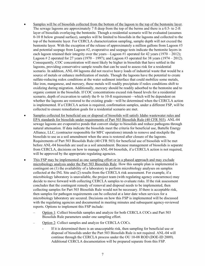
Table 2. Composite sampling requirements for the ANL-04 lagoons.
Lagoon Size Sample Depth
(biosolids) Increments Number of Composite
Samples Lagoon #1 150 × 150 ft 0 to 6 in. 30 3
6 in. to the top of the bentonite layer
30 3
Lagoon #2 50 × 100 ft 0 to 6 in. 30 3 6 in. to the top of the
bentonite layera 30 3
Lagoon #3 125 × 400 ft 0 to 6 in. 30 3 6 in. to the top of the
bentonite layer 30 3
a. The depth of biosolids in Lagoon #2 is estimated to be 0 to 6 in. If it is determined that the biosolids are deeper than 6 in. and there is adequate sample volume, then the subsurface composite samples will be sent to the laboratory for analysis.
increments are collected, the increments of biosolids will be thoroughly mixed in the pan using a stainless steel or disposable spoon/trowel. The mixed composite sample then will be divided into quarters (this can be done visually) where equal amounts of biosolids will be consecutively collected from each quarter and transferred to a clean labeled sample container until enough biosolids is collected to fill the sample container. A separate systematic sampling pattern with a different random start location will be used for each subsequent composite sample.
The sampling tool does not need to be cleaned between increments but will be replaced or cleaned between composite samples. Reused sampling equipment will be decontaminated as described in Section 3.3.
Once sampling is complete, labeled sample containers will be prepared for shipment. Sections 3.7, 3.8, and 3.9 describe requirements to prepare samples for off-Site shipment.
3.2 Sample Design and Procedure for Part 503 Biosolids Rule This FSP will use a simple random sampling approach to assess pathogens and nutritive value of
ANL-04 biosolids. Metal analysis from CERCLA composite samples can be used to evaluate whether mean concentrations exceed regulatory requirements under the Part 503 Biosolids Rule.
3.2.1 Study Area Boundary
Seven random grab samples will be collected from each lagoon from the surface to the top of the bentonite layer. Figure 5 shows the seven randomly selected grids where grab samples will be collected. Table 3 identifies sampling requirements to assess pathogens and nutritive value of the ANL-04 biosolids.
Table 3. Grab sampling requirements for the ANL-04 lagoons.
Lagoon Size Sample Depth
(biosolids) Number of Grab
Samples
Lagoon #1 150 × 150 ft 0 in. to the top of the bentonite layer 7
Lagoon #2 50 × 100 ft 0 in. to the top of the bentonite layer 7
Lagoon #3 125 × 400 ft 0 in. to the top of the bentonite layer 7

14
3.2.2 Sampling Procedure
Project personnel will mark the center of each randomly selected grid. Personnel may make adjustments within the grid to ensure obstructions are avoided. Changes to grid or sample locations will be recorded in the field logbook and geographical information system database. Then, using a scoop or soil probe with a lined sampler or equivalent (hand-operated or power-driven), a sample will be collected to the top of the bentonite layer at the marked location. Project personnel will then transfer the sample to a clean labeled sample container. Project personnel will move to the next randomly selected grid, repeating the process until all grab samples are collected from each lagoon.
The sampling tool will be replaced or cleaned between the grab samples. Reused sampling equipment will be decontaminated as described in Section 3.3.
Once sampling is complete, labeled sample containers will be prepared for shipment. Sections 3.7, 3.8, and 3.9 describe requirements to prepare samples for off-Site shipment.
3.3 Decontamination Procedure
Equipment will be inspected and cleaned before use to prevent cross-contamination from another site. Preliminary inspection and cleaning—performed away from the sampling site—consist of removing rust, oil, grease, or any other buildup by scrubbing with a wire brush or sandblasting. Equipment then will be cleaned with a solution of water and detergent, rinsed, and dried.
Decontaminating reusable sampling equipment between replicate samples will include the following steps:
• Clean with a solution of water and detergent by lightly spraying the equipment and using a brush or saturated wipe to remove particulate matter and surface films
• Rinse thoroughly with water
• Dry with clean wipe or let air-dry on clean surface before next use.
An equipment rinsate blank will be collected in accordance with the QAPjP (DOE-ID 2016) to evaluate decontamination procedures. Equipment rinsate blanks are not required if dedicated or disposable equipment is used.
3.4 Sampling and Analysis Requirement A Sample and Analysis Management (SAM) representative will coordinate analyses with a
laboratory that can achieve programmatic requirements. Analysis requirements are summarized in a sampling and analysis plan table provided by SAM personnel. The technical lead and SAM representative will coordinate with the analytical laboratory to ensure that samples arrive at the laboratory to meet holding time requirements. Preservation requirements and maximum sample holding times are obtained from the SAM representative; holding times are defined from the date of sample collection to the date of sample preparation or analysis, unless otherwise specified.
Samples will be analyzed as identified in Table 4. Any changes to number of samples, expected approach, or analytical or quality control (QC) requirements will be noted in the project-specific log notes because these types of changes are inherent to sampling activities. If scope does not change, such as redefining the population or significantly changing the strategy, incidental changes that occur throughout the planning process may be documented in the sample log notes and do not require a Document Revision Form. A field change form (Form 412.47) can be initiated, as needed, for unexpected conditions encountered in the field. A sampling logbook will be maintained in accordance with company procedures for logbooks.

15
Table 4. Summary of sampling information for the ANL-04 study area.
Regulatory Requirement Analysis
Remediation Goal/ Regulatory Limit Analytical Method
Sample Medium
Sample Methoda
Inorganics
CERCLA Total metals UTS list: OU 10-08 Work Plan, Table 6 (DOE-ID 2010)
SW-846 method (EPA 2016) (or equivalent)
Biosolids Composite
• Antimony
• Arsenic
• Barium
• Beryllium
• Cadmium
• Chromium
• Cyanide
• Lead
• Mercury
• Nickel
• Selenium
• Silver
• Vanadium
• Zinc
Plus
• Copper • Manganese
Part 503 Biosolids Rule
Part 503 Biosolids list Part 503 Biosolids Rule, Table 1 (40 CFR 503) • Arsenic
• Cadmium
• Chromium
• Copper
• Lead
• Mercury
• Molybdenum
• Nickel
• Selenium
• Zinc
Radionuclides
CERCLA Alpha isotopes: OU 10-08 Work Plan, Table 6 (DOE-ID 2010)
SW-846 method (EPA 2016) (or equivalent)
Biosolids Composite
• Am-241
• Np-237
• Pu-iso (238, 239, 240)
• U-iso (234, 235, 238)

Table 4. (continued).
16
Regulatory Requirement Analysis
Remediation Goal/ Regulatory Limit Analytical Method
Sample Medium
Sample Methoda
Gamma spectroscopy:
• Ag-108m • Co-60 • Cs-134 • Cs-137
• Eu-152 • Eu-154 • Eu-155 • Ra-226
Specific radionuclide analysis:
• Ni-63 • Pu-241
• Sr-90
Nutrientsb DEQ characterization for beneficial use or disposal of biosolids (DEQ 2011)
Total nitrogen NA Nitrate (NO3) as N: preparation by EPA Method 300.0; analysis by SW-846 Method 9056A or EPA Method 300.0 (or equivalent) Percent organic matter: ASTM D2974 (or alternate test)c
Biosolids Grab
Total Kjeldahl nitrogen NA EPA 351.2 or Standard Methods 4500 (Rice et al. 2012) (or equivalent)
Total ammonia-N NA EPA 300.0 or Standard Methods 4500 (Rice et al. 2012) (or equivalent)

Table 4. (continued).
17
Regulatory Requirement Analysis
Remediation Goal/ Regulatory Limit Analytical Method
Sample Medium
Sample Methoda
Nitrate-nitrite N NA Standard Methods 4500 (Rice et al. 2012) (or equivalent)
Total phosphorus NA EPA 6010D (or equivalent)
Total potassium NA EPA 6010D (or equivalent)
Pathogensb Part 503 Biosolids Rule
Fecal coliformd Part 503 Biosolids Rule, Class A, Alternative 4 (503.32(a)(6)(i)) OR Part 503 Biosolids Rule, Class B, Alternative 1 (503.32(b)(2)(ii))
Standard Methods 9221E or 9222D (Rice et al. 2012) (or equivalent)
Biosolids Grab
Salmonella sp. bacteriad Part 503 Biosolids Rule, Class A, Alternative 4 (503.32(a)(6)(i))
Standard Methods 9260D (Rice et al. 2012) (or equivalent)
Enteric virusese Part 503 Biosolids Rule, Class A, Alternative 4 (503.32(a)(6)(ii))
ASTM D4994 (or equivalent)
Helminth ovae Part 503 Biosolids Rule, Class A, Alternative 4 (503.32(a)(6) (iii))
EPA/625/R-92/013, Appendix I (or equivalent) (EPA 2003)

Table 4. (continued).
18
Regulatory Requirement Analysis
Remediation Goal/ Regulatory Limit Analytical Method
Sample Medium
Sample Methoda
Other DEQ characterization for beneficial use or disposal of biosolids (DEQ 2011)
Total solids NA Standard Methods 2540B (Rice et al. 2012) (or equivalent)
Biosolids Grab
pH NA EPA 9045C (or equivalent)
a. Sample preservation and holding times will be specified in the field guidance form. b. Nutrient and pathogen results are to be reported as dry weight basis. c. The most common and reliable test for estimating plant available N in soil is a soil nitrate (NO3) test along with Organic Matter Content. However, ICP-contracted
laboratories do not perform an Organic Matter Content analysis. If it is determined ANL-04 biosolids will be land-applied, a laboratory that performs this analysis will be identified.
d. Either fecal coliform or Salmonella sp. bacteria can be analyzed for Class A biosolids. The project team will determine which one will be analyzed if samples are required. e. Helminth ova and enteric viruses analysis is required for Class A biosolids and not for Class B. CERCLA Comprehensive Environmental Response, Compensation, and Liability Act DEQ Department of Environmental Quality (Idaho) EPA Environmental Protection Agency ICP Idaho Cleanup Project NA not applicable OU operable unit UTS Universal Treatment Standard

19
3.5 Sampling Equipment
Sampling equipment, documentation, and any other supplies that will be used for sampling are identified below. Before sampling, new or decontaminated equipment will be obtained to support sampling activities. The following equipment and supplies will be used for sampling, as needed:
• Soil probe with a lined sampler or equivalent (hand-operated or power-driven)c
• Hand tools (e.g., disposable spades, spoons, scoops, or soil auger)
• Aluminum pans or equivalent
• Personal protective equipment designated in work control documents authorized by facility management or as identified by project safety representative
• Survey paint, pin flags, or stakes to mark sample locations
• Chain-of-custody forms
• Sample logbook
• Wipes or absorbent towels
• Sample containers and labels
• Authorized work control documents to direct fieldwork (e.g., this FSP, job safety analysis, and technical procedure or work order)
• Container to stage samples and ice if samples are not immediately shipped off-Site for analysis
• Adhesive tape
• Individual sample bags and waste bags
• Aluminum foil
• Measuring tape
• Pens and markers
• Custody seals.
3.6 Sampling Documentation and Management
The field team lead will be responsible for controlling and maintaining all field documents and records and for verifying that all documents submitted to the company SAM group are maintained in good condition. All entries will be in indelible black ink. Errors will be corrected by drawing a single line through the error and entering the correct information. All corrections will be initialed and dated.
Any deviations from this FSP will be brought to the attention of project management and technical lead. Any changes (e.g., to the number of samples, the expected approach, or the analytical or QC requirements) will be noted in the project-specific log notes and may require a Document Revision Form (ICP 2016). A field change form (Form 412.47) can be initiated for a procedure, when needed to continue work, for unexpected conditions encountered in the field. Incidental changes that occur throughout the planning process may be documented in the sample log notes and do not require a Document Revision Form.
c. A sample probe with an outside diameter of 2 cm (0.8 in.) will achieve the ≥2-kg (4.4-lb) targeted sample mass.

20
3.6.1 Sample Logbook
The QAPjP discusses use of field team leader, calibration, and shipping logbooks; however, this sampling event will only require the use of a sample logbook, in which case all pertinent information will be recorded in the sample logbook, and no other logbooks are necessary. The sample logbook will be used to record information necessary to interpret the analytical data, including the following:
• Sample collection method (e.g., which tools were used) and location (e.g., sample number and depth)
• Shipping information; samples will be relinquished to off-Site laboratory for analysis
• All team activities
• Problems encountered
• Names of visitors
• List of site contacts
• Corrective actions taken as a result of field audits
• Discrepancies or changes from the description in this FSP, with regard to the approach, depth, location, analyses, number of samples, presence of moisture, or physical limitations.
Sampling logbooks will be maintained in accordance with company procedures. The logbook will be signed and dated at the end of each day’s sampling activities.
3.7 Sample Designation and Labeling
Each sample bottle will contain a label identifying the unique field sample number. Uniqueness is required for maintaining consistency and preventing the same identification code from being assigned to more than one sample. A systematic character code will be used to uniquely identify all samples. SAM personnel will generate a sampling and analysis plan table, numbers, and labels that correlate directly to characterization sampling. The label is completed and placed on the bottle in accordance with company procedures.
3.8 Chain of Custody
All samples collected will be managed by chain of custody in accordance with company procedures. Chain-of-custody procedures will begin immediately after the first sample is collected. At the time of sample collection, the sampling team will initiate a chain-of-custody form for each sample. All samples will remain in the custody of a sampling team member until custody is transferred to the analytical laboratory sample custodian. Upon receipt at the laboratory, the sample custodian will review the sample labels and the chain-of-custody form to ensure completeness and accuracy. If discrepancies are noted during this review, then immediate corrective action will be sought, and the sampling team member(s) will relinquish custody, as identified on the chain-of-custody form. Upon completion of the corrective action, the laboratory sample custodian will sign and date the chain-of-custody form, signifying acceptance of delivery and custody of the samples. Chain of custody will be performed in accordance with approved company procedures.

21
3.9 Sample Transport
Once sampling is complete, samples will be prepared for shipment, and the applicable shipping papers will be completed, in accordance with company procedures. Samples will be packaged, and packages will be provided to the Packaging and Transportation shipper for transport.
3.10 Waste Management
Wastes generated during the characterization project will include sampling equipment such as used disposable pans, scoops, wipes, and personal protective equipment. Waste Generator Services (WGS) personnel will coordinate waste disposal activities in accordance with company procedures. Waste will be bagged, placed in containers, labeled, and stored in an approved storage area pending disposition. Waste Determination and Disposition Forms (Form 435.39) will be prepared for determining the disposition routes for all waste generated during sampling and analysis. Waste generated under this FSP will be managed as CERCLA waste.
The analytical laboratory will dispose of samples submitted to them for analyses or return them to the requester as stated in the applicable task order statement. Samples returned from the laboratory will be accepted only if the original label is intact and legible. If the samples are returned, Waste Management personnel are responsible to properly disposition the samples with the assistance of project management. All waste must be characterized, and preapproval for disposal must be obtained from WGS personnel.
3.10.1 Waste Minimization
Throughout the sampling activity, emphasis will be placed on waste-reduction methods. Practices to be implemented to support waste minimization include, but are not limited to, the following:
• Restrict materials (especially hazardous materials) to those needed to perform work
• Substitute recyclable items for disposable items
• Reuse items, when practical
• Segregate contaminated from uncontaminated waste
• Segregate reusable items (e.g., personal protective equipment and tools).

22
4. SAMPLE ANALYSIS
Laboratories on the company Qualified Suppliers List will be used to analyze the samples in accordance with project requirements, such as those given in the applicable statement of work for laboratory services. Project-specific request-for-analyses forms or task order statements identify additional requirements for laboratory analysis. The following subsections identify analysis requirements for this sampling project.
4.1 Analytical Methods
To ensure that data of acceptable quality are obtained from the sampling project, standard EPA laboratory methods or technically appropriate methods for analytical determinations will be used to obtain sample data. The SAM program is responsible for obtaining laboratory analytical services for the required analyses listed in Table 2, in accordance with company procedures. The SAM program will prepare statements of work for laboratory services that include the analytical methods and the project-required detection limits for each analysis type. Any deviations from this information will be fully documented, and the laboratory will inform the project manager and technical lead of the deviations.
4.2 Instrumentation Calibration Procedure
Laboratory instruments will be calibrated in accordance with each specified analytical method. The laboratory quality assurance plan must include requirements for calibrations when specifications are not listed in analytical methods. Calibrations that typically are not called out in analytical methods include ancillary laboratory equipment and verification of reference standards used for calibration and standard preparation. Laboratory documentation includes calibration techniques and sequential calibration actions, performance tolerances provided by the specific analytical method, and dates and frequencies of the calibrations. All analytical methods have specifications for equipment checks and instrument calibrations. The laboratory will comply with all method-specific calibration requirements for all requested parameters. If failure of instrument calibration or equipment is detected, the instrument will be recalibrated, and all affected samples will be analyzed using an acceptable calibration.
4.3 Laboratory Records
Laboratory records are required to be maintained in accordance with the specific laboratory quality assurance plan. The SAM analytical laboratory authorization processes provide assurance that the analytical laboratories authorized to perform analysis maintain an appropriate laboratory quality assurance plan that addresses laboratory records.

23
5. DATA MANAGEMENT AND DOCUMENT CONTROL The following subsections describe data management and document control for this sampling
effort.
5.1 Data Reporting The final data package documentation will conform to the criteria specified in the applicable
statement of work for laboratory services. The statement of work prepared by the SAM organization is the standard means by which company projects define analytical data deliverable requirements to laboratories. All laboratories used by this project will adhere to documents that establish technical and reporting standards.
5.2 Data Validation Analytical data validation is the comparison of analytical results versus the requirements
established by the analytical method. Validation involves evaluation of all sample-specific information generated from sample collection to receipt of the final data package. Data validation is used to determine whether analytical data are technically and legally defensible and reliable. The final product of the validation process is the validation report. The validation report communicates the quality and usability of the data to the decision-makers.
Data generated for this project will undergo external validation, which SAM personnel will arrange. Standard plus raw data and Level B validation will be requested for all sample data reports generated during this project. The validation report will contain an itemized discussion of the validation process and results. Copies of the data forms annotated for qualification will be attached to the report.
5.3 Data Quality Assessment The project data quality assessment and validation process is used to determine whether the data
meet the project DQOs. DQOs for this sampling event are defined in Section 2. Additional steps of the data quality assessment process may involve data plotting, testing for outlying data points, and other statistical analyses relative to the characterization project DQOs. Quality assessment objectives for this project will meet the minimum requirements as established in the QAPjP (DOE-ID 2016) and will be performed as follows:
• Precision is the measure of the reproducibility of measurements under a given set of conditions and can be evaluated by the use of duplicate samples collected in the field. To meet the QAPjP goals for measurements of precision, duplicates will be collected at a minimum frequency of 1/20 environmental samples or 1/day/matrix, whichever is less.
• Accuracy is a measure of the closeness of an individual measurement or the average of a number of measurements to the true value. Accuracy is demonstrated by using control samples, blind QC samples, or matrix spikes. The QAPjP recommends collecting a field blank when subsurface soil (>6 in.) is collected and analyzed for radionuclides. However, because radionuclide cross-contamination is not a concern for the area—ANL-04 is outside the complex and not exposed to operations—field blanks are not required.
• Representativeness expresses the degree to which sample data accurately and precisely represent a characteristic of a population parameter at a sampling point or environmental condition. The representativeness criterion is best satisfied by confirming that sampling locations are selected properly and a sufficient number of samples is collected to meet the confidence level required by the intended use of the data. Sections 2 and 3 describe the basis for the sample design and procedure to satisfy this requirement.

24
• Completeness is a measure of the number of samples collected and analyzed and is expressed as a percentage of the number of samples planned to be collected and analyzed. The completeness goal for sampling activities is 90% for non-critical samples and 100% for critical samples. Samples collected under this FSP are considered non-critical with a completeness goal of 90%.
• Comparability is the qualitative term that expresses confidence that two data sets can contribute to a common analysis and interpolation. Two data sets are not collected for this sampling project; thus, requirements for comparability are not applicable.

25
6. HEALTH AND SAFETY REQUIREMENTS
Personnel who sample, transport, and analyze the soil must work under PLN-2128 and project-specific work control that contains hazard identification and mitigation. Project-specific work control must comply with the Integrated Safety Management System in accordance with company policies and procedures.

26
7. PROJECT ORGANIZATION AND RESPONSIBILITIES
This section describes the positions associated with this sampling event. These responsibilities may change throughout the sampling effort. An organization chart will be prepared to show the name of the individual performing the function and will be retained in work control documentation. Most of the position descriptions are provided in PLN-2128, “Environmental Restoration Project Health and Safety Plan.” Descriptions of those positions not included in PLN-2128 are provided in Sections 7.1 through 7.3. The following lists key positions or support areas:
• Environmental Restoration CERCLA director
• Environmental Restoration project manager
• Environmental Restoration facility manager
• Battelle Energy Alliance program manager
• Technical lead
• Environment, safety, and health
• Environmental and regulatory support (CERCLA)
• Quality assurance
• Waste Generator Services
• Waste Generator Services waste technical specialist
• Sample and Analysis Management program
• Field team personnel.
7.1 Technical Lead The technical lead is responsible for field activities and for all personnel, including craft personnel,
assigned to work at the project location. The technical lead is the interface between operations and project personnel and works to ensure that the sampling team achieves project objectives in a safe and efficient manner. The technical lead coordinates all document preparation, field and laboratory activities, data evaluation, risk assessment, dose assessment, and design activities.
7.2 Waste Generator Services Waste Technical Specialist The INL Site WGS waste technical specialist ensures that waste disposal complies with approved
INL Site waste management procedures. WGS personnel help solve waste management issues at the task site. In addition, WGS personnel prepare appropriate documentation for waste disposal and make the proper notifications, as required.
7.3 Sample and Analysis Management SAM personnel are responsible for helping to define analyses that will meet project requirements,
generating the sampling and analysis plan table and field guidance form, and generating and issuing sample labels. SAM personnel determine the laboratory that will provide analytical services, based on established policies and contracts; ensure that the analytical laboratory uses acceptable methods; and prepare the statement of work. SAM personnel also track analytical progress and perform a cursory review of the final data packages. SAM personnel obtain data validation, as directed by the project.

27
8. REFERENCES
40 CFR 503, 2015, “Standards for the Use or Disposal of Sewage Sludge,” Code of Federal Regulations, Office of the Federal Register, October 2015.
40 CFR 503.32(a)(6), 1999, “Class A - Alternative 4,” Code of Federal Regulations, Office of the Federal Register, August 1999.
40 CFR 503.32(b)(2), 1999, “Class B - Alternative 1,” Code of Federal Regulations, Office of the Federal Register, August 1999.
42 USC § 9601 et seq., 1980, “Comprehensive Environmental Response, Compensation and Liability Act of 1980 (CERCLA/Superfund),” United States Code, December 11, 1980.
54 FR § 48184, 1989, “National Priorities List of Uncontrolled Hazardous Waste Sites; Final Rule,” Federal Register, November 21, 1989.
ANL, 1994, Site ANL-04, Track 1 Investigation Decision Documentation Package, ANL-W Sewage Lagoons, Administrative Record Document ID 5758, Argonne National Laboratory-West, July 1994.
ASTM D2974, 2014, “Standard Test Methods for Moisture, Ash, and Organic Matter of Peat and Other Organic Soils,” ASTM International, November 2014.
ASTM D4994, 2014, “Standard Practice for Recovery of Viruses from Wastewater Sludges,” ASTM International, March 2014.
Cahn, Lorie S., 2015, Preliminary Risk Evaluation for CERCLA Site ANL-04 Sewage Lagoons, Operable Unit 10-08, RPT-1368, Rev. 0, Idaho Cleanup Project, November 2015.
DEQ, 2011, Guidance for Land Application of Municipal Biosolids, Idaho Department of Environmental Quality, December 2011.
DOE-CH, 1998, Final Record of Decision Argonne National Laboratory – West, Operable Unit 9-04, Idaho National Engineering and Environmental Laboratory, W7500-000-ES-4, U.S. Department of Energy Chicago Operations Office; U.S. Environmental Protection Agency, Region 10; Idaho Department of Health and Welfare, Division of Environmental Quality, September 1998.
DOE-CH, 2004, Explanation of Significant Difference for Argonne National Laboratory–West, Operable Unit 9-04, Idaho National Engineering and Environmental Laboratory, Document ID 24867, U.S. Department of Energy Chicago Operations Office; U.S. Environmental Protection Agency; Idaho Department of Environmental Quality, May 2004.
DOE-ID, 1991, Federal Facility Agreement and Consent Order for the Idaho National Engineering Laboratory and Action Plan, Idaho National Laboratory Administrative Record No. 1088-06-29-120, U.S. Department of Energy Idaho Operations Office; U.S. Environmental Protection Agency, Region 10; Idaho Department of Health and Welfare, December 1991.
DOE-ID, 2009, Operable Unit 10-08 Record of Decision for Site-Wide Groundwater, Miscellaneous Sites, and Future Sites, DOE/ID-11385, Rev. 0, U.S. Department of Energy Idaho Operations Office; U.S. Environmental Protection Agency, Region 10; Idaho Department of Environmental Quality, September 2009.

28
DOE-ID, 2010, Operable Unit 10-08 Remedial Design/Remedial Action Work Plan, DOE/ID-11418, Rev. 0, U.S. Department of Energy Idaho Operations Office, August 2010.
DOE-ID, 2016, Quality Assurance Project Plan for Waste Area Groups 1, 2, 3, 4, 5, 6, 7, 9. 10, and Removal Actions, DOE/ID-10587, Rev. 11, U.S. Department of Energy Idaho Operations Office, June 2016.
EPA, 2003, Control of Pathogens and Vector Attraction in Sewage Sludge, EPA/625/R-92/013, U.S. Environmental Protection Agency, July 2003.
EPA, 2006, Guidance on Systematic Planning Using the Data Quality Objectives Process, EPA QA/G-4, EPA/240/B-06/001, U.S. Environmental Protection Agency, February 2006.
EPA, 2016, SW-846 Online, https://www.epa.gov/hw-sw846, U.S. Environmental Protection Agency, Web page updated March 23, 2016, Web page visited May 11, 2016.
EPA Method 300.0, 1993, “Determination of Inorganic Anions by Ion Chromatography,” Rev. 2.1, U.S. Environmental Protection Agency, August 1993.
EPA Method 351.2, 1993, “Determination of Total Kjeldahl Nitrogen by Semi-Automated Colorimetry,” Rev. 2.0, U.S. Environmental Protection Agency, August 1993.
EPA Method 6010D, 2014, “Inductively Coupled Plasma-Optical Emission Spectrometry (ICP-AES),” Rev. 4, U.S. Environmental Protection Agency, July 2014.
EPA Method 9056A, 2007, “Determination of Inorganic Anions by Ion Chromatography,” Rev. 1, U.S. Environmental Protection Agency, February 2007.
Form 412.47, 2016, “ICP Document Field Change (DFC),” Rev. 7, Idaho Cleanup Project, March 2016.
Form 435.39, 2015, “Waste Determination & Disposition Form (WDDF),” Rev. 11, Idaho Cleanup Project, January 2015.
ICP, 2016, Document Management Document Revision Form, http://icp-edms.inel.gov/docs/drf_menu.html, Idaho Cleanup Project, Web page visited April 6, 2016. (Note: This is an internal Idaho Cleanup Project web page and may not be publicly accessible.)
IDAPA 58.01.16, 2010, “Wastewater Rules,” Idaho Administrative Procedures Act, Idaho Department of Environmental Quality, March 2010.
PLN-2128, 2013, “Environmental Restoration Project Health and Safety Plan,” Rev. 7, Idaho Cleanup Project, January 2013.
Portage, 2005, Remedial Action Report for Waste Area Group 9, Operable Unit 9-04 at the Idaho National Laboratory, PORTAGE-05-002, Rev. 1, Portage Environmental, Inc., June 2005.
Rice, Eugene W., Rodger B. Baird, Andrew D. Eaton, and Lenore S. Clesceri, eds., 2012, Standard Methods for the Examination of Water and Wastewater, American Water Works Association, 2012.