field pilot testing of a new integrated membrane system ... · water pre-treatment system that can...
TRANSCRIPT

AWWA and AMTA Membrane Technology Conference/San Antonio, TX, USA REF: Edalat
Page - 1 - of 16
Field Pilot Testing of a New Integrated Membrane System for Enhanced Oil Recovery and Hydraulic Fracturing Produced Water Treatment
Authors: Arian Edalat, Mark Harrington, Gil Hurwitz, Subir Bhattacharjee, Eric Hoek, Dian
Tanuwidjaja, Anna, Jawor, Jinwen Wang Presenter: Arian Edalat, Ph.D. Vice President – Commercial Projects Water Planet Inc. United States of America [email protected] Abstract Reuse and recycle of oil and gas produced water constitutes a new frontier of desalination. Application of reverse osmosis (RO) for desalination in such scenarios is currently impractical, as the influent water cannot reliably be treated to a sufficient level of purity to enable its use as an RO feed. A major shortcoming of conventional oil-field pre-treatment processes is their inability to maintain consistently low-levels of free oil & grease, turbidity and silt density index (SDI) in their effluent. Water Planet Inc. (WPI) has developed a patent-pending, integrated mechanical and membrane separation platform for oil and gas produced water treatment. The mechanical components (1) remove free oil and suspended solids and (2) capture and de-water the oil product (i.e., oil product recovery). The ultrafiltration (UF) membrane then filters out the remaining suspended solids, bacteria, clay fines and any hexane extractable oil hydrocarbons from the water. Field-testing was performed over five weeks at a California steam-flood oil production site (~15 – 18 oAPI) employing a wide range of temperature (up to 85 oC), with various oil concentrations in the influent (up to 15%) and solids (up to 5%). Operating throughput of the pilot was up to 800 barrels per day. Under every operating condition, the treated water consistently showed non-detectable oil and grease, turbidity below 1 NTU, and SDI below 1. The effluent from the platform was then run through several reverse osmosis membranes (RO) in bench scale laboratory tests. The RO membranes significantly reduced TDS, conductivity, sulfate, magnesium, hardness, TOC, boron, calcium and chloride from the UF filtrate. This paper describes details of the pilot experience, highlighting the performance of the system toward production of consistent tertiary treated water quality, summarizing the performance metrics. In conclusion, it appears that the process can perform as a robust, modular, low footprint oil-field produced water pre-treatment system that can render the downstream water polishing and desalination applications more reliable in many conventional, EOR, and thermal EOR oilfields.

AWWA and AMTA Membrane Technology Conference/San Antonio, TX, USA REF: Edalat
Page - 2 - of 16
I. Introduction
1.1 Produced Water Treatment Extracting hydrocarbon resources co-produces a significant amount of water, which is industrially termed produced water. How much produced water is generated at a given site is highly dependent on reservoir characteristics (age, geology) and production technique, and thus varies from one location to another. Water to oil ratios in oil and gas production reported in the United States vary from 2 to 43. The current national average is close to 5, and expected to increase to 12-15 by year 2020 [1]. Produced water is usually brackish or hypersaline with considerable amounts of dispersed and dissolved hydrocarbons and solids. Conventional treatment of produced water involves a cascade of gravity based mechanical separators designed to remove the dispersed hydrocarbons and suspended solids in a stage-wise manner. The sequential stages in this cascade are often referred to as primary (gravity-induced flotation/sedimentation of free oil and suspended solids), secondary (air/gas-induced flotation of macro-emulsion) and tertiary (nutshell filtration of micro-emulsion). Advanced water treatment or desalination may follow. This involves the removal of dissolved hydrocarbons and remaining dissolved solids by thermal or membrane desalination [2,3]. Optimal performance of advanced treatment technologies is highly reliant on a consistent quality of water generated by the pretreatment process. The problem with many of the conventional pre-treatment technologies is that rapid fluctuations in their influent (feed) water qualities cause variations in effluent water quality. WPI’s integrated membrane system (IMS) reported here addresses the above issue by innovatively combining accelerated gravity separation with ultrafiltration to create an absolute barrier towards dispersed hydrocarbons and suspended solids regardless of the quality of the water upstream. The main purpose of this paper is to report the performance of the platform during a recent field test in a thermal enhanced oil recovery (tEOR) application in California. 1.2 Pilot Objectives The main objectives for the pilot test were to:
• Demonstrate how the IMS platform responds to variable feed water qualities and conditions; namely, oil & grease, suspended solid concentrations, and temperature.
• Understand the membrane fouling and permeability reduction mechanisms inherent to the produced water at a tEOR application.
• Learn how conventional operational philosophies relating to membrane cleaning and flux management perform under these conditions.
• Develop a membrane fouling management procedure, which would include optimization of parameters such as flux, temperature, and frequency of backwash, CIP and CEB.
• Evaluate differences in RO membrane separation performance and fouling.

AWWA and AMTA Membrane Technology Conference/San Antonio, TX, USA REF: Edalat
Page - 3 - of 16
1.3 Pilot Site The site chosen for pilot was the Careaga lease in San Luis Obispo County, California, operated by Santa Maria Energy (SME). This location was specifically selected as it provided multiple tie-in points to verify the performance of the process when treating influents of varying oil and solid contents. The challenging nature of the oil and solids in the produced water provided a platform to evaluate the robustness and reliability of the platform. The site employs cyclic steam stimulation (CSS) enhanced oil recovery technique and produces 100 to 200 barrels of heavy oil (15 - 18 °API) per day. It also co-produces 5,000 to 7,000 barrels of produced water per day. This water is de-oiled on site to a level sufficient for reinjection back into the ground. The current produced water treatment process practiced by SME consists of a sequence of large two phase separators. A simplified schematic of the process is shown in figure 1.
Figure 1: Photograph and process flow diagram describing the process currently in use at SME to treat
produced water. The actively producing wells on the Careaga lease generate a fluid which typically contains 5-10% free oil and grease and up to 3% solids. Product streams from different wells are combined and sent first to a two-phase separator, the objective of which is the removal of produced gases. Water wettable solids are also partially separated in this step, and periodically removed. The liquid fraction of the two-phase separator is then passed to a 30-foot wash tank for gravitational oil, water, and further solids separation. After a 24-hour residence time in the wash tank, the oil layer is removed as crude oil product with BS&W <3%. The water fraction, de-oiled to approximately to a few hundreds to 1000 ppm oil and grease, moves next to a clarifier tank, where the water’s oil content is further reduced. Finally, water with between 50 and 200 ppm oil and grease is collected in the holding tank before being injected into a disposal well.
Two$Phase$Separator$
Wash$$Tank$
(24$hrs$RT)$
Clarifier$Tank$
Water Few hundreds to thousand ppm oil
Produced Gas
Holding$Tank$
From Wellhead 5- 10% Oil 1-3% Solids
Water To PW
Injection Wells
Crude oil BS&W<3% Skimmed oil Skimmed oil
AWWA and AMTA Membrane Technology Conference/San Antonio, TX, USA REF: Edalat
Page - 4 - of 16
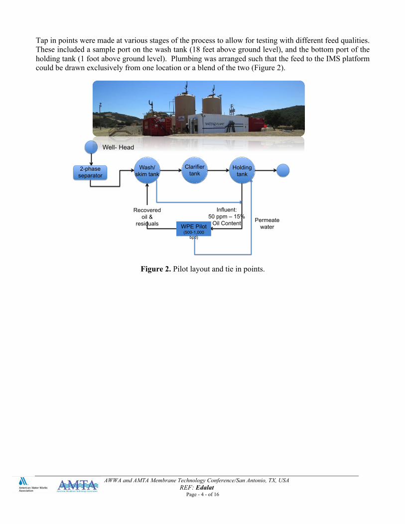
Tap in points were made at various stages of the process to allow for testing with different feed qualities. These included a sample port on the wash tank (18 feet above ground level), and the bottom port of the holding tank (1 foot above ground level). Plumbing was arranged such that the feed to the IMS platform could be drawn exclusively from one location or a blend of the two (Figure 2).
Figure 2. Pilot layout and tie in points.
2-phase separator
Clarifier tank
Wash/skim tank
Holding tank
Recovered oil &
residuals Permeate water WPE Pilot
(500-1,000 bpd)
Well- Head
Influent: 50 ppm – 15%
Oil Content

AWWA and AMTA Membrane Technology Conference/San Antonio, TX, USA REF: Edalat
Page - 5 - of 16
II. METHODS AND EQUIPMENT USED 2.1. Technology Platform The IMS features a patent pending process combining accelerated gravity separation followed by a high recovery ceramic UF designed to treat influent waters with oil and suspended solids contents of up to 30% and 5%, respectively (Figure 3). The upfront mechanical separation process is a combination of a tank and centrifugal separator specifically designed for oil and gas production activities. The objective is to separate the bulk of the oil and solids from water and recover a high quality crude oil. The membrane separator then polishes the water by removing the bulk of remaining colloidal suspended particles and oil droplets, producing a consistently clean filtrate water product. The system is modular, compact, fully automated and operated by a novel intelligent flux management control program ensuring improved fouling tolerance, minimized downtime, and optimized operation. In the pilot plant, the two processes are integrated within one 20 ft shipping container. The maximum throughput of the pilot system is 1000 barrels per day (30 gallons per minutes, 7 m3 per hour). The effluent produced by the platform is devoid of oil (below the minimum detectable limit of 5 mg/L hexane extractable O&G) and solids (turbidity below 1). One of the design objectives of integrated process was to ensure that the silt density index (SDI) of the treated water was brought below 3, such that one can operate within the warranty terms and maximize lifetime expectancy of conventional RO membranes should these be deployed to treat the platform’s effluent. The platform can be used as a robust and reliable RO pre-treatment technology in a variety of applications, including conventional oil & gas, thermal EOR, hydraulic fracturing flow back, produced water treatment and reuse, and other industrial oil - water separation applications.
Figure 3. Conceptual illustration of the integrated membrane system.
2.2. Membrane The membrane used was a commercially available ceramic ultrafiltration membrane with a molecular weight cut off of 300 kDa. The membrane arrangement consisted of 91 monolith ceramic cartridges. Each cartridge measured 1.2 meters in length and contained 19 individual feed flow channels. This resulted in a total membrane filtration area of 22.4 m2.

AWWA and AMTA Membrane Technology Conference/San Antonio, TX, USA REF: Edalat
Page - 6 - of 16
2.3. Analytical Methods The produced water quality of the feed and filtrate was analyzed using standard methods and equipment as outlined in table 1.
Table 1: A list of the measured parameters as well as the methods and equipment used. Parameter Method Instrument Conductivity Electrode Measurement Hach, model: CDC401 pH Electrode Measurement Hach, model: IntelliCAL PHC101 TOC, DOC Mutli sample measurement Shimadzu, model: TOC-‐VCSH with
ASI-‐V Autosampler TDS, TSS, TSS Standard Method 2540B, 2540C,
2540D Lab-based per standard method
turbidity Nephlometric Measurement Turbidity meter, model: 2100 N, Hach
Sulfate, nitrate, alkalinity, COD
Spectrophotometry Hach, model: DR5000 UV-‐Vis
Metals Inductively Coupled Plasma (ICP) Measurement
ICP, model: TJA Radial IRIS 1000 ICP-‐OES
Free oil and grease Surrogate EPA 1664 A (hexane extraction and spectrophotometry)
Turner design, model: TD-‐500
Basic sediments and Water (%) content of the oil
ASTM standard D4007-11 Benchtop centrifuge, Eppendorf, model: 5702
2.4 Test Plan Pilot testing was performed in two distinct phases. The first phase (phase I) consisted of a number of short tests, each with variable feed and operating conditions, and lasting between 1 and 4 hours. Within the first phase, the test was broken up into two tests: (Ia) low oil test (oil and grease <500 ppm) and (Ib) high oil test (oil and grease >500 ppm. The second phase of testing consisted of a challenge test, where the system was run continuously for nearly 72 hours. While parameters such as permeate flux and trans-membrane pressure (TMP) varied, recovery was held constant at 90% for the entirety of testing. 2.5 Operation The IMS was operated using a fully automated control system that ran the startup, regular operation, clean in place, and shutdown operations automatically. A human machine interface (HMI) integrated with the PLC system allowed for collection of pertinent data and generated alarms as a result of any fault. The pilot operation took place at a site which had to conform to all the safety codes associated with a class: I division: II hazardous site conditions. Special precautions were necessary to manage any VOC emissions as well as any H2S related hazards. The equipment was monitored 24 hours per day at the field site.

AWWA and AMTA Membrane Technology Conference/San Antonio, TX, USA REF: Edalat
Page - 7 - of 16
III. RESULTS AND DISCUSSIONS 3.1 Feed and Filtrate Water Quality The quality of the produced water fed to various stages of the platform as well as the filtrate throughout the pilot are summarized in Table 2. The ionic composition of the water quality is stable. The oil content and solid content were consistently non-detectable suggesting a successful pretreatment for an RO system. The SDI levels of the filtrate were within 0.4-0.8. Single values reported in Table 2 are average values of several measurements.
Table 2: Water quality data for various sample points throughout the integrated system. Mechanical
/Membrane Separator Feed
Membrane Filtrate
pH 8 7 Conductivity (mS/cm) 23 24 Color (NTU) 14 16 Alkalinity (mg/L as CaCO3)
987 983
Hardness (mg/L as CaCO3)
387 361
COD (mg/L) 1,370 1,357 TOC (mg/L) 116 127 TDS (mg/L) 14,083 14,412 Chloride (mg/L) 7,985 8,480 Aluminum (mg/L) ND ND Boron (mg/L) 27 31 Barium (mg/L) 27 30 Calcium (mg/L) 109 109 Iron (mg/L) ND ND Magnesium (mg/L) 47 52 Sodium (mg/L) 4445 5077 Silicon (mg/L) 57 63 oil content 50 ppm to 15% ND Solid content (mg/L) 0.08-‐5.00% ND Turbidity 20-‐928 0.27-‐0.80 SDI NM* 0.4-0.8
*Not Measured

AWWA and AMTA Membrane Technology Conference/San Antonio, TX, USA REF: Edalat
Page - 8 - of 16
3.2 Phase Ia. Low Oil Cut Tests
Feed Quality The first part of phase I testing consisted of treatment of an influent with oil and grease levels below 500 ppm. The feed water was sourced from the holding tank in SME’s process. Changing conditions of the feed yielded variable water qualities from day to day. Only the membrane component was operated during this phase.
Table 3: Feed characteristics for the low oil cut test. Average Minimum Maximum Oil & Grease 47 ppm 2.7 ppm 230 ppm Turbidity 300 NTU 20 NTU 928 NTU
Temperature 40.4°C 24°C 68°C Operation The permeability normalized for temperature effects on water viscosity was reported as a primary means for tracking membrane performance. Figure 4 illustrates normalized permeability, temperature, and feed oil content plotted against time for phase Ia of testing. The permeability normalized for temperature effects on water viscosity was reported as a primary means for tracking membrane performance. Figure 4 illustrates normalized permeability, temperature, and feed oil content plotted against time for Phase Ia of testing.
Figure 4: Low cut oil test
Upon system startup with the new membrane, we observed normalized permeability of 140 LMH/bar. Over the course of the first 11 hours of testing, permeability fell to 110 LMH/bar, equating to a 21% loss.

AWWA and AMTA Membrane Technology Conference/San Antonio, TX, USA REF: Edalat
Page - 9 - of 16
Backwash took place every 20 minutes for the majority of the test for 8 seconds. Two CIPs were performed during the low oil cut test. The first was done after 6 hours of operation. Results initially following the CIP were positive. Permeability was recovered from approximately 45 LMH/bar before the CIP to 145 LMH/bar immediately after. The key takeaway from these results is that despite drastic variability in the feed water quality and condition, the system operated stably while producing a consistent filtrate quality with nearly 100% rejection of both parameters. 3.2 Phase Ib. High Oil Cuts Feed The second part of phase I tests was performed with high oil cuts defined as free oil and grease levels above 500 ppm, the feed to the system reached oil contents up to 15% by blending the wash tank and the wastewater streams. The ratio of the two feeds was controlled by actuation of hand valves on each process line, just upstream of a manifold where the streams were combined before being fed to the platform. This way, a given target oil cut could be achieved and controlled. Both the mechanical and membrane components of the platform were operated during this phase.
Table 4: Feed characteristics for the high oil cut test. Average Minimum Maximum Oil & Grease 1420 ppm* 575 ppm 150,000 ppm Turbidity 220 131 NTU 337 NTU
Temperature 49°C 26°C 85°C *The average concentration in the membrane feed.
Figure 5: Summary of performance during phase Ib at various stages of the platform.
Mechanical))Separa-on)
Membrane)Separa-on)Separated water
Oil Content = 500-1,200 mg/L
Collected Sludge/Solids
20—70% solid content
Concentrate Oil content = 0.5-1%
Light Phase Oil content = up to 15%
Treated Water: Oil content: non-detect
Turbidity<1 NTU SDI<1
Average : 400 BPD (12 gpm)
Influent Oil Content: up to 15% Solid Content: 0.8 – 2% Temperature = Up to 70 °C

AWWA and AMTA Membrane Technology Conference/San Antonio, TX, USA REF: Edalat
Page - 10 - of 16
Operation Figure 5 summarizes the performance of various components of the system during this phase of testing. The main focus of these tests was on the operation of the mechanical component, either on a standalone basis, or along with the membrane component. The mechanical separator consistently produced a deoiled water containing between 500 to 1,200 mg/L of oil (over 99% removal efficiency). The BS&W of the separated oil was 4-15%. Sludge separated by the mechanical component had about 20-70% solid content (measured by BS&W method). For membrane operation, similar to the low oil cut test, the high oil test is a composite of a variety of shorter interval tests, totaling 7.5 hours, and each test was performed at different operating conditions. The permeability, temperature, and feed oil content over the course of the high oil cut test is shown in Figure 6.
Figure 6: High cut oil test.
At the beginning of the high oil cut test, permeability was observed at 76 LMH/bar. By hour 23, permeability had fallen to 60 LMH/bar. This 16 LMH/bar drop corresponds to 11% of the initial membrane permeability. This is a relatively slow loss in permeability, only 1.5% per hour, compared to the average 4.8% per hour loss observed during the low oil cut test despite the variability in feed quality. Furthermore, variability in feed water quality had less impact on permeability. This reflects reaching the state of stability as the platform controls have identified the safe operating window with regards to flux, the frequencies of backwash, and CIPs. Average backwash duration was identified at every 10 minutes for 8 seconds. 3.3 Challenge Test The final portion of the pilot consists of a challenge test. It constituted nearly 72 hours run time with a CIP break at about 50 hours. Parameters for the challenge test were chosen as the optimal operating conditions after reviewing the data generated during the low and high oil cut tests. Only the membrane component was operated.
AWWA and AMTA Membrane Technology Conference/San Antonio, TX, USA REF: Edalat
Page - 11 - of 16
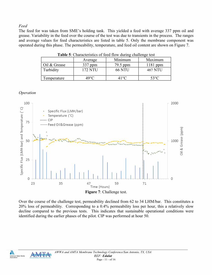
Feed The feed for was taken from SME’s holding tank. This yielded a feed with average 337 ppm oil and grease. Variability in the feed over the course of the test was due to transients in the process. The ranges and average values for feed characteristics are listed in table 5. Only the membrane component was operated during this phase. The permeability, temperature, and feed oil content are shown on Figure 7.
Table 5: Characteristics of feed flow during challenge test Average Minimum Maximum
Oil & Grease 337 ppm 79.5 ppm 1181 ppm Turbidity 172 NTU 66 NTU 487 NTU
Temperature 49°C 41°C 53°C Operation
Figure 7: Challenge test.
Over the course of the challenge test, permeability declined from 62 to 34 LHM/bar. This constitutes a 20% loss of permeability. Corresponding to a 0.4% permeability loss per hour, this a relatively slow decline compared to the previous tests. This indicates that sustainable operational conditions were identified during the earlier phases of the pilot. CIP was performed at hour 50.

AWWA and AMTA Membrane Technology Conference/San Antonio, TX, USA REF: Edalat
Page - 12 - of 16
3.4 Full Pilot Run The permeability, temperature, and feed oil content for the entire 81 hours of operation are presented in figure 5.
Figure 5: Full pilot test plot of normalized permeability, temperature, and oil feed content.
Viewing the entire pilot test on a single plot, it becomes apparent that relatively stable operation was achieved at approximately hour 24, corresponding to the beginning of the challenge test. During the first 23 hours of testing, the system experienced significant and extreme variations in the feed water quality while the system identified the sustainable operational conditions. Once these conditions were identified, however, permeability trend stabilized.

AWWA and AMTA Membrane Technology Conference/San Antonio, TX, USA REF: Edalat
Page - 13 - of 16
IV. REVERSE OSMOSIS TESTS Permeate from the IMS Platform was filtered through reverse osmosis (RO) membrane (Hydranautics SWC5) using a dead-end filtration cell (Sterlitech, HP4750). The average permeate flux was controlled at 8 GFD with applied pressure of 550 psi at 25 °C and 80% recovery. Pictures of the raw and tested RO membranes are shown in Figure 6 and quality UF filtrate feed and RO permeate are shown in Table 6. As demonstrated above, reverse osmosis membrane can successfully polish the UF filtrate from the IMS Platform. TDS, conductivity, sulfate, magnesium hardness and TOC were significantly reduced, while boron, calcium hardness and chloride were partially removed.
Figure. Raw RO membrane (left) and tested RO membrane (right).
Table. Concentrations and RO rejections of constituents in the UF permeate
UF Permeate RO Permeate Rejection
pH
6.81 7.35 -- Conductivity mS/cm 40.7 3.09 92.4%
TOC mg/L 141.8 15.94 88.8% B mg/L 30 10 66.7% Ca mg/L as CaCO3 136 88 35.3% Mg mg/L as CaCO3 271 24 91.1% Cl mg/L 3,400 512 84.9%
SO42- mg/L 113 0 100.0%
TDS mg/L 17,173 1,433 91.7%

AWWA and AMTA Membrane Technology Conference/San Antonio, TX, USA REF: Edalat
Page - 14 - of 16
V. CONCLUSIONS A major shortcoming of conventional oil-field pre-treatment processes is their inability to sustain a consistently low-level of free oil & grease, turbidity and SDI in their effluent. WPI has developed a patent-pending, integrated mechanical and membrane separation platform for oil and gas produced water treatment. The mechanical components (1) remove free oil and suspended solids and (2) capture and de-water the oil product (i.e., oil product recovery). Membranes then filter out the remaining suspended solids, bacteria, clay fines and any hexane extractable oil hydrocarbons from the water. Field-testing was performed over five weeks at a California steam-flood oil production site (~15 – 18 oAPI) employing a wide range of temperature (up to 85 oC), with various oil concentrations in the influent (up to 15%) and solids (up to 5%). Typical operating throughput of the pilot was up to 800 barrels per day. Under every operating condition, the treated water consistently showed non-detectable oil and grease, turbidity below 1 NTU, and SDI below 1. The membrane operation was initially challenged by fouling propensity of the feed water due to variability in feed oil and solids concentration as well as temperature swings. It is believed that the effect of temperature on the rheological properties of the feed oil has a significant impact on the fouling propensity of produced water. For these tests, feed temperatures below 45°C were particularly challenging. The first 23 hours of the operation was spent on identifying the sustainable operating conditions whereby the loss of flux/permeability become minimal. This included identifying the optimum frequency of backwash and clean in place event. The optimum fouling management scenario was concluded as a combination of backwashing every 10 minutes for 8 seconds as well as an alkaline/acidic CIP every 50 operational hour. Less than 5% liquid waste was produced by the system. The average specific energy consumption for the mechanical and membrane components of the platform were evaluated at: 0.22 kWh/m3 and 0.84 kWh/m3 of throughput, respectively. The effluent from the platform was then run through reverse osmosis membrane (RO) at benchscale. It was observed that RO could successfully polish the UF filtrate from platform. TDS, conductivity, sulfate, magnesium hardness and TOC were significantly reduced, while boron, calcium hardness and chloride were partially removed from one-stage RO treatment. In conclusion, it appears that the platform can perform as a robust, modular, low footprint oil-field produced water pre-treatment system that can render the downstream water polishing and desalination applications more reliable in many conventional, EOR, and thermal EOR oilfields. Finally, WPI is currently looking into RO designs whereby rejection of boron, calcium hardness and chloride as well as other constituents of concern encountered in oilfield applications.

AWWA and AMTA Membrane Technology Conference/San Antonio, TX, USA REF: Edalat
Page - 15 - of 16
VI. REFERENCES
1. Clark, C.E., and J.A. Veil. Produced water Volumes and Management Practices in the United States, Report prepared by the Environmental Science Division, National Energy Technology Laboratory, 2009, ANL/EVS/R-‐09
2. Ahmadun Fakhru’l-‐Razia, Alireza Pendashteha, Review of technologies for oil and gas produced water treatment, Journal of Hazardous Materials, Volume 170, Issues 2–3, 30 October 2009, Pages 530–551
3. Igunnu, E.T., Chen, G.Z. Produced water treatment technologies, International Journal of Low-‐Carbon Technologies, Volume 9, Issue 3, September 2014, Pages 157-‐177

AWWA and AMTA Membrane Technology Conference/San Antonio, TX, USA REF: Edalat
Page - 16 - of 16
VII. ACKNOWLEDGEMENT WPI would like to acknowledge Santa Maria Energy for making their site accessible for these tests.