field operations guide - kansas
TRANSCRIPT

U.S. Army Corps of Engineers Urban Search and Rescue Program
Urban Search & Rescue
Structures Specialist
FIELD OPERATIONS GUIDE
7th Edition, 4th Printing
June 2014 (Changes are to pages 5-37 thru 5-50, plus minor
corrections on 1-28 & 7-3 – see Disasterengineer.org)

US&R STRUCTURES SPECIALIST FIELD OPERATIONS GUIDE (FOG)
FOREWORD
This Field Operations Guide (FOG) was developed by the FEMA US&R Structures Sub-group in cooperation with U.S. Army Corps of Engineers (USACE), as a working reference tool for US&R Rescue Team Personnel, especially Structures Specialists (StS), during response operations. It condenses information provided during training, and was designed to be expanded in order to incorporate new information.
In this FOG, Sections 1 through 4 are identical to the same sections of the smaller US&R Shoring Operations Guide (SOG). That SOG is intended for use of Rescue Specialists in constructing shoring and other rescue operations. In addition to the first 4 sections, this FOG contains Equipment Operation Procedures, Operational Check Lists, Engineering Data, Tables and Forms that make it a more useful reference for the StS.
Users are encouraged to suggest changes that can be incorporated into future editions of this FOG. Suggestions should be made to:
Disasterengineer.org
e-mail: [email protected] This Publication is intended for the use of US&R Structures Specialists and Rescue Team Personnel. It may be printed by them, or their organizations, for their use.
TABLE OF CONTENTS
The following Sections are contained in this FOG. Each Section has an Outline that gives the order in which subjects are presented
NO. CONTENTS of SECTION
1 Hazard I.D. and Failure Modes by Building Type US&R Field Communication Procedures FEMA US&R Marking System FEMA US&R Shoring Symbols Design Loads and Quick Weight Estimating
2 Vertical Shoring Construction, Graphics and Step by Step Text
3 Lateral Shoring Construction, Graphics and Step by Step Text
4 Repair & Strengthening Techniques Shoring Frequently Asked Questions Glossary of Terms
5 Equipment Operation Procedures
6 General Reference – RST & Communication Procedures, Sample Calculations, Map Symbols, CIS, Rope/Knots, Crane & Excavator Signals
7 Useful Tables - for Wood, Connectors, Steel, Rigging & Cranes, Anchors & Pneumatic Struts
8 USACE StS General Instructions & Checklists
9 FEMA StS General Instructions,
Description of Duties and Checklists StS Forms
1
2
3
4
5
6
7
8
9

US&R STRUCTURES SPECIALIST FIELD OPERATIONS GUIDE (FOG)
DEFINITIONS of ENGINEERING TERMS
Kips or K – 1000 pounds Tons or T – 2000 pounds Breaking Strength – Force required to cause complete failure of a structure, given in pounds, Kips or Tons, usually associated with Wire Rope. Ultimate Strength (also Ultimate Load & Ultimate Capacity) – Force required to cause complete failure of a structure, given in pounds or Kips. Design Load (also Design Strength & Design Capacity) – Some fraction of Ultimate Strength that is used to determine the Size or Number of Structural Components (posts, etc.) to support a Load at Low Risk of Collapse. Working Load, Safe Working Load – same as Design Load Design Factor, Safety Factor – Ultimate Strength divided by Design Load. This Factor may be as high as 10 to 20 when using Wire Rope or Climbing Rope to suspend humans. For most building structures, it is normally not less than about 3. Design Factor for Wood Structures – due to the variation in the quality of any grade and species of wood it is difficult to predict the Design Factor for any individual shore built using the guidelines of this document.
The Shoring Squad should select the posts for straightness of grain and minimum number of knots.
The lumber should be good quality Douglas Fir or Southern Pine (if not the reductions in strength noted in Sect 4, FAQ, should be applied). Note that pressure treating Doug. Fir & Southern Pine does not significantly reduce strength.
When nailing 2x lumber with 16d nails one must avoid splitting in order to maintain joint integrity. In cases where 16d are closely spaced, the 16d coated cooler nail (.148" x 3.25") is preferred.
For more Definitions, see Sect. 4, Glossary.

US&R STRUCTURES SPECIALIST FOG DISASTER SITE REFERENCE DATA
1-1
1
INTRODUCTION to SECTION 1 This section contains Documents that are Useful References for the US&R Disaster Site, listed as follows:
Hazard I.D. & Failure Modes by Bldg Type Page 1-2 US&R Field Communication Procedures 1-16 On-Site Emergency Signaling Procedures 1-18 US&R Building Marking System 1-19 FEMA US&R Shoring Symbols 1-30 Design Loads & Weight Estimating 1-31 Basics of a Monitoring Plan 1-32
HAZARD I.D. and FAILURE MODE SUMMARY The following pages contain brief descriptions and graphics of the most common building classifications used for US&R Evaluations:
Building Types are: Wall Systems Frame Systems Light Frame, multi-story Heavy Floor, C.I.P. Heavy Wall, URM & Tilt-Up Heavy Steel Bldgs Precast Buildings Light Metal Bldgs
Pages for each bldg type present the characteristics, typical failure modes, hazards, check points, plus hazard reduction and victim access suggestions.
CRITICAL ISSUES: Buildings may be varied, of combined types, and complicated. Focus on determining the amount of Potential Energy that
remains (heavy structure/objects that can collapse or fall. Important to separate Brittle from Ductile Behavior. Judgments may not be able to be precise. Partial collapse is most difficult to assess.
Make judgments based on what type of forces are expected after initial event (aftershock, high winds, etc).
Victim Survivability is highly dependent on void formations, void stability, and void accessibility.
One should always consider Risk/Reward Ratio. The viability of the various Mitigation Choices is dependent on
the potential for Ductile Behavior of the damaged structure.

US&R STRUCTURES SPECIALIST FOG DISASTER SITE REFERENCE DATA
1-21-2
MULTI-STORY LIGHT FRAME BUILDING - HAZARDS
CHARACTERISTICS Mostly wood frame, box type – up to 4 stories. Residential or Light Commercial.
KEY PERFORMANCE ASPECTS Many walls create redundant structures w/ductile failure
modes, dependant on sheathing type. Presence of concrete floor fill can enhance possibility of
P-delta collapse. TYPICAL FAILURE MODES Failure in Wall Sheathing – Racking of Walls. Failure should be slow and noisy. Soft/Weak stories can rack and collapse.
COMMON COMBINATIONS Many are built over R/C parking garages.

US&R STRUCTURES SPECIALIST FOG DISASTER SITE REFERENCE DATA
1-3
1
MULTI-STORY LIGHT FRAME BUILDING (continued) EXPECTED PERFORMANCE – for the following: Progressive Collapse – Extensive connection failures.
Members & components are likely to remain intact. E. Quake – Generally good performance - common failure
is ductile racking of first story. Racked stories are subject to ratcheting and P-delta collapse in Aftershocks.
Explosion – Walls become disconnected from floors (horizontal diaphragms), leading to part or total collapse.
Fire – Rapid combustion and collapse unless fire resistant. High Energy Impact – Little resistance to collapse in
immediate area. Remainder of structure remains stable. Wind – Damage is highly dependent on wind speed vs.
shape and proper detailing. Tornados can destroy even well constructed wood buildings.
Struct Overload/Defect – Roof failures due to snow, especially on longer span roofs.
CHECK POINTS Badly cracked and/or leaning walls. Leaning first story in multi-story buildings. Cracked, leaning/loose veneer or chimney. Offset of building from foundation. Separated porches, split level floors/roof. Connection failures - nail pullout/bolt pull-through.
HAZARD REDUCTION Shut off gas and reduce other fire hazards. Avoid or pull-down damaged veneer and chimneys. Place vertical and/or lateral (diagonal) shores. Monitor changes in racked/leaning structures.
VICTIM ACCESS Vertical access through floor/roof from above collapsed area. Horizontal entry through existing cavities, or through walls. Remove or shore hazards near victims, if required.
US&R STRUCTURES SPECIALIST FOG DISASTER SITE REFERENCE DATA
1-41-4
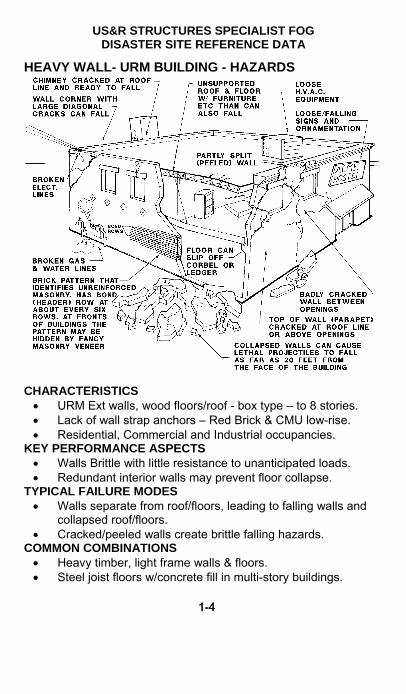
HEAVY WALL- URM BUILDING - HAZARDS
CHARACTERISTICS URM Ext walls, wood floors/roof - box type – to 8 stories. Lack of wall strap anchors – Red Brick & CMU low-rise. Residential, Commercial and Industrial occupancies.
KEY PERFORMANCE ASPECTS Walls Brittle with little resistance to unanticipated loads. Redundant interior walls may prevent floor collapse.
TYPICAL FAILURE MODES Walls separate from roof/floors, leading to falling walls and
collapsed roof/floors. Cracked/peeled walls create brittle falling hazards.
COMMON COMBINATIONS Heavy timber, light frame walls & floors. Steel joist floors w/concrete fill in multi-story buildings.

US&R STRUCTURES SPECIALIST FOG DISASTER SITE REFERENCE DATA
1-5
1
HEAVY WALL- URM BUILDING (continued) EXPECTED PERFORMANCE – for the following: Progressive Collapse – URM walls likely to disintegrate,
and interior structure may stand independently. E. Quake - Poor performance - out of plane ext wall failures,
loss of connection to floors leading to partial or total collapse. Many lethal Aftershock falling and collapse hazards.
Explosion – Walls become disconnected from floors (horizontal diaphragms), leading to part or total collapse.
Fire – Loss of roof/floors will leave walls unbraced. Collapsing roof/floors can thrust walls in or out.
High Energy Impact – Ext URM walls disintegrate upon impact leaving lethal falling hazards & possible floor collapse. Massive masonry is more resistant.
Wind – Roof vulnerable to uplift, leading to partial or total collapse or roof & walls. Massive masonry is more resistant.
Struct Overload/Defect – Roof failures due to ponding and snow. Wood decay, brick disintegration or remodeling in older buildings.
CHECK POINTS Loose, broken parapets and ornamentation. Connections between exterior walls and roof/floors. Cracked wall corners and openings, plus peeled walls. Unsupported and partly collapsed roof/floors.
HAZARD REDUCTION Shut off gas and reduce other fire hazards. Diagonally shore. tie-back, avoid, remove hazardous walls. Shore hazardous roof/floor beams, etc. Monitor changes in racked/leaning structures.
VICTIM ACCESS Vertical access through floor/roof from above collapsed area. Horizontal entry through existing cavities and openings. Remove bricks by hand, excavator, or crane w/clamshell. Remove or shore hazards near victims, if required.
US&R STRUCTURES SPECIALIST FOG DISASTER SITE REFERENCE DATA
1-61-6
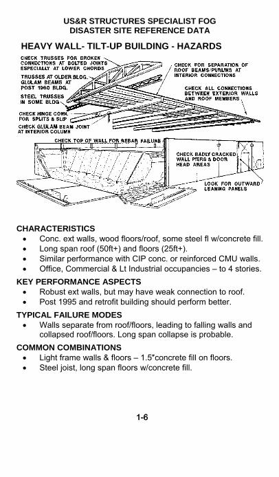
HEAVY WALL- TILT-UP BUILDING - HAZARDS
CHARACTERISTICS Conc. ext walls, wood floors/roof, some steel fl w/concrete fill. Long span roof (50ft+) and floors (25ft+). Similar performance with CIP conc. or reinforced CMU walls. Office, Commercial & Lt Industrial occupancies – to 4 stories.
KEY PERFORMANCE ASPECTS Robust ext walls, but may have weak connection to roof. Post 1995 and retrofit building should perform better.
TYPICAL FAILURE MODES Walls separate from roof/floors, leading to falling walls and
collapsed roof/floors. Long span collapse is probable.
COMMON COMBINATIONS Light frame walls & floors – 1.5″concrete fill on floors. Steel joist, long span floors w/concrete fill.
US&R STRUCTURES SPECIALIST FOG DISASTER SITE REFERENCE DATA
1-7
1
HEAVY WALL- TILT UP BUILDING (continued) EXPECTED PERFORMANCE – for the following: Progressive Collapse – Out-leaning wall/walls could
progress to roof/floor collapse in bay adjacent to exterior. Remainder could stand independently – but poorly braced.
E. Quake – Pre 1995 - poor performance – out of plane ext wall failures, loss of connection to roofs leading to partial or total collapse. Lethal Aftershock falling and collapse hazards.
Explosion – Walls become disconnected from floors (horizontal diaphragms), leading to part or total collapse.
Fire – Loss of roof/floors will leave walls unbraced. Collapsing roof/floors can thrust walls in or out.
High Energy Impact – Impact on exterior walls likely to be localized. Could lead to localized roof/floor collapse.
Wind – Roof vulnerable to uplift, leading to partial or total collapse or roof and walls. Penetration through large doors can lead to critical uplift and blow-out pressures.
Struct Overload/Defect – Roof failures due to ponding and snow. Wood decay in older buildings.
CHECK POINTS Connections between exterior walls and roof/floors. Beam to beam and other interior roof connections.
HAZARD REDUCTION Diagonal or Raker shore concrete walls. Shore hazardous roof/floor beams, etc. May pull-down leaning walls after dealing w/roof support. Monitor changes in racked/leaning structures.
VICTIM ACCESS Vertical access through floor/roof from above collapsed area.
Horizontal entry through existing cavities and openings. Cut holes in wall panels, 2 feet min. from joints. Remove large wall panels and roof sections by crane.

US&R STRUCTURES SPECIALIST FOG DISASTER SITE REFERENCE DATA
1-81-8
PRECAST BUILDINGS - HAZARDS
CHARACTERISTICS Factory built lightweight concrete parts – up to 14 stories. Systems w/o interior concrete panels are greatest problem.
KEY PERFORMANCE ASPECTS Highly engineered systems, but often brittle connections. Little capacity for unanticipated loads. Residence type may be highly redundant due to many walls.
TYPICAL FAILURE MODES Failure of interconnections between parts leading to partial or
total collapse, depending on redundancy.
COMMON COMBINATIONS May have CIP floor slabs or reinforced concrete topping. Use of Reinforced Masonry shear walls and metal stud walls. PC is used as floor panels in masonry & steel buildings.

US&R STRUCTURES SPECIALIST FOG DISASTER SITE REFERENCE DATA
1-9
1
PRECAST BUILDINGS (continued) EXPECTED PERFORMANCE – for the following: Progressive Collapse – Failed single story columns have
lead to progressive collapse. Heavy elements vs. brittle connections are critical issues. Members retain strength.
E. Quake – Very poor performance – except for multi-wall residence buildings. Failed connections lead to partial or total collapse. Aftershock falling, shifting and collapse hazards.
Explosion – Poor performance due to weak-link connections leading to part or total collapse.
Fire – Could cause annealing of tendons and prestress loss. High Energy Impact – Impact on ext elements likely to be
localized. Brittle connections could be damaged. Wind – Unlikely to be damaged by wind. Exterior skin and
curtain walls could be damaged/destroyed. Struct Overload/Defect – Failures in connections, leading to
cascading structure failure. Members should retain integrity.
CHECK POINTS Beam/column connections, broken welds and cracked
corbels. Column cracking at top, bottom and wall joints. Wall connections at floors, columns and foundation. Badly cracked walls and columns plus falling hazards.
HAZARD REDUCTION Remove/avoid leaning/hanging, concrete elements. Shore damaged roof/floor beams, especially next to bad
columns. Remove/shore unstable wall and floor elements. Monitor changes in racked/leaning structures.
VICTIM ACCESS Vertical access through thin horizontal sections from above. Horizontal entry through existing cavities and openings. Cut holes in wall panels, 2 feet min. from joints. Carefully remove large wall/floor sections by crane.

US&R STRUCTURES SPECIALIST FOG DISASTER SITE REFERENCE DATA
1-101-10
HEAVY FLOOR BLDGS (CIP non-DUCTILE) - HAZARDS
CHARACTERISTICS Cast in Place (CIP) concrete frames and highway structures,
– up to 12 stories. Few concrete walls, but URM infill in older buildings. Eastern US – (Western pre 1975) Office & Commercial.
KEY PERFORMANCE ASPECTS Brittle failure modes when loaded beyond capacity. Post 1975 Ductile Frames in western US have systems that
can absorb considerable energy w/o loss of integrity.
TYPICAL FAILURE MODES Beam-column joint failure or column shear leading to partial
or total collapse. Collapse can be partial or complete pancake.
COMMON COMBINATIONS May have URM and/or metal stud wall partitions.

US&R STRUCTURES SPECIALIST FOG DISASTER SITE REFERENCE DATA
1-11
1
HEAVY FLOOR BLDGS (CIP non-DUCTILE) (continued)
EXPECTED PERFORMANCE – for the following: Progressive Collapse – Members likely to break into
smaller pieces. Rubble piles may shift. E. Quake – Very poor performance – Brittle failures of
columns and beam/column connections, leading to partial or pancake collapse. Aftershocks cause added collapse, falling hazards and shifting.
Explosion – Poor slab performance due to reverse gravity loading can lead to loss of column stability and collapse.
Fire – May cause spalling of concrete cover on all elements. High Energy Impact – Damage limited to area of impact.
Could leave damaged members of questionable strength. Wind – Unlikely to be damaged by wind. Exterior skin and
curtain walls could be damaged/destroyed. Struct Overload/Defect –Construction falsework failures
most common. Members break into pieces w/poor integrity.
CHECK POINTS Beam/column connections above and below floors. Badly confined concrete in columns (empty basket). Diag. shear cracks in beams and cracking in slabs near cols. Attachment of URM walls and other heavy objects. Cracks in concrete shear walls and stairs.
HAZARD REDUCTION Shore/avoid badly cracked slabs, beams and/or column. Shore/avoid overloaded slabs due to punching shear. Remove/shore unstable wall and floor elements. Monitor changes in racked/leaning structures.
VICTIM ACCESS Vertical access through existing access shafts. Vertical access by cutting through slabs from above victims. Horizontal entry through existing cavities and openings. Cut non-bearing/infill walls after careful assessment. Remove large pieces by crane, after rebar has been cut.
.
US&R STRUCTURES SPECIALIST FOG DISASTER SITE REFERENCE DATA
1-121-12
HEAVY STEEL FRAME BUILDING - HAZARDS
CHARACTERISTICS Heavy ″W″ steel beam & column framing – 2 to many stories. Office and Commercial Occupancies, some industrial.
KEY PERFORMANCE ASPECTS Normally well engineered, but performance is dependent on
ductility of connections. PC floor systems as suspect. Welded connections may be subject to brittle failure. Diagonally braced frames may have buckled cols or braces.
TYPICAL FAILURE MODES Connection failure leading to partial collapse. Total collapse
is extremely rare.
COMMON COMBINATIONS May have masonry, precast or metal panel exterior walls. CIP floors over metal deck, or PC/CIP directly on steel.

US&R STRUCTURES SPECIALIST FOG DISASTER SITE REFERENCE DATA
1-13
1
HEAVY STEEL FRAME (continued) EXPECTED PERFORMANCE – for the following: Progressive Collapse – Rare, since members maintain
integrity even with damaged/failed joints. E. Quake - Good performance of frame - Failure of diagonal
bracing and fracture of welded joints have occurred. Facing, especially PC panels could fall and are danger in Aftershocks.
Explosion – Good performance of frame but wall & floor panels could be dislodged. Frame collapse is unlikely.
Fire – Plastic deformation of floors and some joint failure. Strength is regained upon cooling. Collapse very rare.
High Energy Impact – Impacted members are severed/destroyed. Connection failures near impact only.
Wind – Frame at low risk – Skin, especially glass may be destroyed leading to interior partition failure.
Struct Overload/Defect – Failures during erection and long-span failures are most common. Members maintain integrity with failures at joints.
CHECK POINTS Indications of movement – plumb corners, stair and non-
structural damage – as clues to potential structure damage. Main beam to column connections – remove finishes as
required. Broken PC floor and miscellaneous beam bolt connections.
HAZARD REDUCTION Shore beams near damaged or broken connections. Remove/avoid/tieback damaged exterior facing. Monitor changes in racked/leaning structures.
VICTIM ACCESS Vertical access by cutting through slabs from above victims. Horizontal entry through existing cavities & openings. Remove or shore hazards near victims, if required.

US&R STRUCTURES SPECIALIST FOG DISASTER SITE REFERENCE DATA
1-141-14
LIGHT METAL BUILDING – HAZARDS
CHARACTERISTICS Light-gage steel, pre-fab metal buildings – up to 3 stories. Industrial and Commercial Occupancies – most 1 story.
KEY PERFORMANCE ASPECTS Highly engineered with little redundancy or over-strength. Very flexible, especially in lateral direction.
TYPICAL FAILURE MODES Weakest Link Behavior – loss of sheathing allows buckling,
leading to collapse of supporting structure. Diagonal rod bracing elongation & joint failure.
COMMON COMBINATIONS May have masonry, precast or tilt-up exterior walls. May have wood or metal interior partitions and mezzanine.

US&R STRUCTURES SPECIALIST FOG DISASTER SITE REFERENCE DATA
1-15
1
LIGHT METAL BLDGS (continued) EXPECTED PERFORMANCE – for the following: Progressive Collapse – Joint failure and member buckling
could lead to part or complete collapse. E. Quake – Good performance – Failure of rod bracing is
common, but collapse is rare. Minor aftershock response. Explosion – Skin blown away, possibly leading to frame/roof
collapse. Entire building blown away in some cases. Fire – Rapid loss of strength and collapse due to heating.
Long span structure could suddenly collapse. High Energy Impact – Little resistance to impact. Damage
may involve several bays of structure. Wind – At high risk – as skin is blown away, frames/trusses
can buckle and collapse. Frames can rack and collapse. Struct Overload/Defect – Lateral torsion buckling of built-up
members. Joint failure and member buckling, leading to part or complete collapse.
CHECK POINTS Broken, elongated and/or buckled rod bracing & connections. Buckled purlins, truss members, and steel frames. Broken and/or elongated bolt connections + anchor bolts.
HAZARD REDUCTION Shore and/or diagonally brace racked building frames. Remove loose or lightly connected members and sheathing. Monitor changes in racked/leaning structures.
VICTIM ACCESS Vertical/Horizontal access by removal or cutting sheathing. Horizontal entry through existing cavities and openings. Remove or shore hazards near victims, if required.

US&R STRUCTURES SPECIALIST FOG DISASTER SITE REFERENCE DATA
1-161-16
COMMUNICATIONS PROCEDURES Effective communication is vital to the safe and successful opera-tions of personnel assigned to a mission in the urban disaster environment. This is extremely important for clear, concise communications between the separate entities, or between personnel within those entities, that will be involved in a major response to an urban disaster. This would include emergency response and command personnel from the effected and adjacent jurisdictions, DOD personnel, state and federal officials and the various US&R task forces deployed to the disaster. The following procedures are identified to promote this standardization for the Structures Specialist: Phonetic Alphabet
Voice Communications Procedures On-Site Emergency Signaling Procedures
PHONETIC ALPHABETA - alpha (Al fah) B - bravo (BRAH voh) C - charlie (CHAR lee) D - delta (DELL tah) E - echo (ECK oh) F - foxtrot (FOKS trot) G - golf (GOLF) H - hotel (HOH tell) I - india (IN dee ah) J - juliet (JEW lee ett) K - kilo (KEY low) L - lima (LEE mah) M - mike (MIKE)
N - november (no VEM ber) O - oscar (OSS car) P - papa (pah PAH) Q - quebec (keh BECK) R - romeo (ROW me oh) S - sierra (SEE air rah) T - tango (TANG go) U - uniform (YOU nee form) V - victor (VIK tah) W - whiskey (WISS key) X - x-ray (ECKS ray) Y - yankee (YANG key) Z - zulu (ZOO loo)

US&R STRUCTURES SPECIALIST FOG DISASTER SITE REFERENCE DATA
1-17
1
COMMUNICATIONS PROCEDURES (continued)
VOICE COMMUNICATIONS PROCEDURES What To Do
Why To Do It
1. LISTEN A. To make sure your transmission won't interfere with another communication.
B. To be aware of other things going on.
2. THINK about what you will say before you transmit.
A. To communicate your idea effectively.
B. To use only the air time needed.
3. MAKE THE CALL. Give: a. the call sign or
identification of the station called.
b. the words "THIS IS" c. the call sign or
identification of the calling station.
A. To be clear. B. To be understood reliably
on the first call. C. To use a procedure that is
universally accepted.
4. COMMUNICATE. Speak clearly. Plain English/no codes. Repeat back critical items
for confirmation.
A. To be understood. B. To be fast. C. To avoid confusion. D. To be accurate.
5. USE PHONETICS for: a. call signs. b. station identification. c. spelling words and
names that are not easily understood
A. To be clear. B. To be accurate. C. To be fast. D. To use a procedure that is
universally accepted.

US&R STRUCTURES SPECIALIST FOG DISASTER SITE REFERENCE DATA
1-181-18
ON-SITE EMERGENCY SIGNALING PROCEDURES
Effective emergency signaling procedures are essential for the safe operation of rescue personnel operating at a disaster site. These signals must be clear and universally understood by all personnel involved in the operation. Air horns or other appropriate hailing devices shall be used to sound the appropriate signals as follows: Cease Operation/All Quiet 1 long blast (3 seconds)
(QUIET)
Evacuate the Area 3 short blasts (1 second each) (OUT, OUT, OUT)
Resume Operations 1 long and 1 short (O - KAY) FEMA BUILDING MARKING SYSTEM
GENERAL: A uniform building marking system has been developed by the FEMA National US&R Response System.
There are 4 categories of FEMA US&R Markings:
Structure Identification Marking
Structure/Hazards Evaluation Marking
Victim Location Marking
Search Assessment Marking
The building marking system was established to ensure:
Differentiation of structures within a geographic area.
Communicate the structural condition and status of US&R operations within the structure.
Identification markings on structures may be made with International Orange spray paint (or crayon), placed on the building surface. In the case of hurricanes where many structures are involved, a system using a "Stick-on" Label should be used
Markings should be placed on normal address side of the structure.

US&R STRUCTURES SPECIALIST FOG DISASTER SITE REFERENCE DATA
1-19
1
STRUCTURE IDENTIFICATION MARKING
If at all possible, the existing street name and building number will be used. If some numbers have been obliterated, attempt should be made to reestablish the numbering based on nearby structures.
If no numbers are identifiable on a given block, then US&R personnel will assign and identify the street name and numbers based on other structures in the proximity. The structures shall then be numbered to differentiate them (using paint or crayon).
700 BLO CK ALPH A S TR EET600 800
706
701
\\\/ // \ //
\\\/ /\\ \\\\ //// \\\
702 704 708 710
705703 707 709
CASE 1 – IF SOME NUMBERS ARE KNOWN, FILL IN BETWEEN
700 B LOC K A LPHA STR EET800 1000
\\\/ // \ //
\\\/ /\\ \\\\ //// \\\
900 902 906 908
905903 907 909
904
901
CASE 2 – IF NO NUMBERS ARE KNOWN, FILL IN USE SMALL NUMBERS

US&R STRUCTURES SPECIALIST FOG DISASTER SITE REFERENCE DATA
1-201-20
STRUCTURE I.D. MARKING (continued)
It is also important to identify locations within a single structure. The address side of the structure shall be defined as SIDE A. Other sides of the structure shall be assigned alphabetically in a clockwise manner from SIDE A.
SIDE A
SIDE B
SIDE C
SIDE D
The interior of the structure will be divided into QUADRANTS. The quadrants shall be identified ALPHABETICALLY in a clockwise manner starting from where the SIDE A and SIDE B perimeter meet. The center core, where all four quadrants meet will be identified as Quadrant E (i.e., central core lobby, etc.).
QUADRANT A QUADRANT D
QUADRANT CQUADRANT B
E
700 BLOCK ALPHA STREET

US&R STRUCTURES SPECIALIST FOG DISASTER SITE REFERENCE DATA
1-21
1
STRUCTURE I.D. MARKING (continued)
Multi-story buildings must have each floor clearly identified. If not clearly discernable, the floors should be numbered as referenced from the exterior. The Grade (or Street) Level Floor would be designated Floor 1 and, moving upward the Second Floor would be Floor 2, etc. Conversely, the First Floor below Grade (or Street) level would be B-1, the Second B-2, etc. For buildings where the street slopes, all at the incident must be informed as to which level will be called the First Floor.
If a structure contains a grid of structural columns, they should be marked with 2' high, orange letters/numbers to further identify enclosed areas. If plans are available, use the existing numbering system. If plans are not available, Letter the columns across the Long Side (Side A in this Example) starting from the left, and Number the columns along the Short Side (Side B in this example) starting from the front, Side A. The story level should be added to each marked Column, and be placed below the Column Locator Mark. Example: "FL-2" = Floor 2.
Column Grid Layout• Use existing column grid - If Known
700 Block Alpha Street
4
3
2
1A GB C D E F

US&R STRUCTURES SPECIALIST FOG DISASTER SITE REFERENCE DATA
1-221-22
STRUCTURE/HAZARDS EVALUATION MARKING
The Structures Spec (or other appropriate TF member) will outline a 2' X 2' square box at any entrance accessible for entry into any compromised structure. Paint sticks, lumber crayons or aerosol spray-paint cans (International Orange color) will be used for this marking system. Peel & Stick labels or stiff paper placards may be used to avoid paint damage. (See example on Page 1-25)
Materials and methods used for marking shall be coordinated with FEMA IST as well as local Authority Having Jurisdiction, in order to avoid confusion with search and other marking.
It is important that an effort is made to mark all normal entry points (Side A if possible) to a building under evaluation to ensure that Task Force personnel approaching the building can identify that it has been evaluated.
The specific markings will be made inside the box to indicate the condition of the structure at the time of the assessment. Any identified hazards will be indicated, outside of the box, on the right side. (Placards have space below the box for comments on hazards)
Normally the marking (or placards) would, also, be made immediately adjacent to the entry point identified as lowest risk. An arrow will be placed next to the box indicating the direction of the lowest risk entrance if the Structure/Hazards Evaluation Marking must be made somewhat remote from this entrance.
All Task Force personnel must be aware of the possibility of, and look for other Structure/Hazards Evaluation markings made on the interior of the building.
As each subsequent assessment is performed throughout the course of the mission, a new TIME, DATE, and TASK FORCE ID entry will be made below the previous entry, or a completely new marking made if the original information is now incorrect.

US&R STRUCTURES SPECIALIST FOG DISASTER SITE REFERENCE DATA
1-23
1
STRUCTURE/HAZARDS EVALUATION MARKING The depiction of the various markings is as follows:
Low Risk for US&R Operations, with low probability of further collapse. Victims could be trapped by contents, or building could be completely pancaked or soft 1st story.
Medium Risk for US&R Ops, and structure is significantly damaged. May need shoring, bracing, removal, and/or monitoring of hazards. The structure may be partly collapsed.
High Risk for US&R Ops, and may be subject to sudden collapse. Remote search operations may proceed at significant risk. If rescue operations are undertaken, significant and time-consuming mitigation should be done.
Arrow located next to a marking box indicates the direction to the lowest risk entrance to the structure, should the marking box need to be made remote from the indicated entrance.
HM
Indicates that a Hazardous Material condition exists in or adjacent to the structure. Personnel may be in jeopardy. Consideration for operations should be made in conjunction with the Hazardous Materials Specialist. Type of hazard may also be noted.

US&R STRUCTURES SPECIALIST FOG DISASTER SITE REFERENCE DATA
1-241-24
STRUCTURE/HAZARDS EVALUATION MARKING (cont.)
The TIME, DATE, and TF ID, are noted outside the box at the right-hand side. This info is made with paint stick or lumber crayon. The paper (or cardboard), stick-on placards may need to be attached using duct tape to assure their positioning.
This example is for a Medium Risk building, and the arrow indicates the direction to the lowest risk entry (possibly a window, upper floor, etc.). Assessment was made on July 15, 1991, at 1:10 PM. There is an indication of natural gas in the structure. The evaluation was made by the #1 TF from the State of Oregon.
It should be understood that this building would not be entered until the Hazmat (natural gas) had been mitigated. When that mitigation is performed, this mark should be altered by a placing a line thru the HM and adding the time and TF who performed the mitigation. An entirely new mark could also be added when the mitigation is done, or after any change in conditions such as an aftershock. To indicate changed conditions when using labels or placards, one may cross-out the hazard if mitigated or just replace the label/placard if appropriate.
Marking boxes may also be placed in each of the specific areas within the structure (i.e., rooms, hallways, stairwells, etc.) to denote hazardous conditions in separate parts of the building.
It should also be noted that the Structure/Hazards Mark might not be made in many situations, such as:
Structures when StS are present at all times during the incident.
Following hurricanes for very simple structures.
7/15/91 1310 hrs.HM - natural gasOR-TF1

US&R STRUCTURES SPECIALIST FOG DISASTER SITE REFERENCE DATA
1-25
1
STRUCTURE/HAZARDS PLACARD Should be printed on adhesive backed, 8.5" x 11" heavy white paper, Rite-on Rain paper, or light cardboard. Cut in half to obtain two placards.
White color was selected to avoid being confused with the Green – Yellow – Red Placards that are placed during Safety Evaluation of Structures by non-US&R Engineers.

US&R STRUCTURES SPECIALIST FOG DISASTER SITE REFERENCE DATA
1-261-26
SEARCH ASSESSMENT MARKING
A separate and distinct marking system is necessary to denote information relating to the victim location determinations in the areas searched. This separate Search Assessment marking system is designed to be used in conjunction with the Structure and Hazards Evaluation marking system. The Canine Search Specialists, Technical Search Specialists, and/or Search Team Manager (or any other Task Force member performing the search function) will draw an "X" that is 2' X 2' in size with International Orange paint stick, lumber crayon or color spray paint (note that K9 may be adversely effected by the Fumes from Spray Paint). This X will be constructed in two operations - one slash drawn upon entry into the structure (or room, hallway, etc.) and a second crossing slash drawn upon exit.
Single slash drawn upon entry to a structure or area indicates search operations are currently in progress. Upon entering a building or a separate wing of a large building, add the Search Team I.D., Date and Time (24hr) of entry. (Next to main entry)
Note: OR-1 is used instead of OR-TF1 to save time. Also 1100 is used to abbreviate 1100hrs
Crossing slash is drawn as personnel exit from the structure or area.
Distinct markings will be made inside the remaining quadrants of the X to clearly denote the search status and findings at the time of this assessment. The marks will be made with carpenter chalk or lumber crayon. The following illustrations define the Search Assessment marks:
OR-1 2-10-02 1100
OR-1 2-10-02 1100

US&R STRUCTURES SPECIALIST FOG DISASTER SITE REFERENCE DATA
1-27
1
SEARCH ASSESSMENT MARKING (continued)
AFTER EXITING & DRAWING the 2nd SLASH, add the following INFO:
TOP QUADRANT - Time and date that the Search Team personnel left the structure.
RIGHT QUADRANT - Personal hazards.
BOTTOM QUADRANT - Number of live and dead victims still inside the structure. ["0" = no victims]
When the Recon Team leaves a structure WITHOUT completing the Search (aftershock, end of shift, etc), then the second slash WILL NOT be made. A Solid Circle is drawn at the mid-length of the First Slash, and Date/Time of Exit, Personal Hazards, & Victim Info will be filled in. Also indication of Quadrants or Floors completed should be added in a BOX below the X, or if the Bldg HAS NOT been entered (as in Hurricanes) mark
No Entry in the BOX.
OR-1 2-10-02 1100
OR-1 2-10-02 1100
2-10-02 1400
RATS
OR-1 2-10-02 1100
2-L 3-D
2-10-02 1400
2-10-02 1400
RATS
2-L 3-D
F = Floors Q = Quadrants or No Entry
OR-1 2-10-02 1100
2-10-02 1400

US&R STRUCTURES SPECIALIST FOG DISASTER SITE REFERENCE DATA
1-281-28
SEARCH ASSESSMENT MARKING (continued)
In most cases, extemporaneous information will not be conveyed using the marking system. This type of communication will usually take place as a result of face-to-face meetings between Search, Rescue, and other components of the Task Force.
Search Markings should be made at each area within a structure, such as rooms, voids, etc, but only information related to the results of the search will be marked upon exiting each space (No Time or TF designation).
An adhesive-backed search mark placard has been approved for use in incidents like Hurricanes and large earthquakes where many structures are involved. All FEMA Task Forces have been supplied with the graphic to be used in creating the stick-on search marks, which should be printed on orange paper. See Library, Disasterengineer.org
VICTIM LOCATION MARKING SYSTEM During the search function it is necessary to identify the
location of potential and known victims.
The amount and type of debris in the area may completely cover or obstruct the location of any victim.
The victim location marks are made by the search team or others aiding the search and rescue operations whenever a known or potential victim is located and not immediately removed.
The victim location marking symbols should be made with orange spray paint (using line marking or "downward" spray can) or orange crayon.
The following illustrates the marking system:

US&R STRUCTURES SPECIALIST FOG DISASTER SITE REFERENCE DATA
1-29
1
VICTIM LOCATION MARKING SYSTEM (cont.)
5’CA-6
5’CA-6CA-6
Make a large (2' x 2' ) "V" w/orange paint near the location of the known or potential victim. Mark the name of the search team as shown. An arrow may need to be painted next to "V" pointing towards the victims location is not immediately near where the "V" is painted. Show distance on arrow.
2
CA-6
2
CA-6
Paint a circle around the "V" when a potential victim has been Confirmed to be alive either visually, vocally, or by hearing sounds that would indicate a high probability of a victim. If more than one confirmed live victim, mark total number under the "V".
2
CA-6
2
CA-6
Paint a horizontal line through the middle of the "V" when a Confirmed victim is determined to be deceased. If more than one confirmed deceased victim, mark the total number under the "V". Use both live and deceased victim marking symbols when a combination of live and deceased victims are determined to be in the same location.
2
CA-6
2
CA-6
Paint an "X" through the Confirmed victim symbol after all victims have been removed from the specific location identified by the marking. Paint new victim symbols next to
additional victims that are later located near where the original victim(s) were removed. (assuming original symbol has been ″X″ed out).

US&R STRUCTURES SPECIALIST FOG DISASTER SITE REFERENCE DATA
1-301-30
FEMA US&R SHORING SYMBOLS These symbols were developed by the FEMA US&R Structures Sub-group, and should be used to map locations of US&R Shoring
Tee Shore
Double T Shore
DT
Vertical Shore (V-3 = 3 posts, V-2 = 2 posts)
Laced Post Shore (at Plywood Laced Post use PLP in box)
Cribbing
Raker Shore - Place vertical side of triangle against wall - Each triangle represents one Raker - Rakers should be installed groups of two
or larger
Horizontal Shore ( H - 3 = 3 struts, H - 2 = 2 struts)
Window or Door Shore (W or D)
H-3
LP
V-3
C
T
R
W or D

US&R STRUCTURES SPECIALIST FOG DISASTER SITE REFERENCE DATA
1-31
1
DESIGN DEAD LOADS for BUILDING MATERIALS
Normal Reinforced Concrete = 150 pcf = .087 lbs per cubic inch
Struct. Steel = 490 pcf = .28 lbs per cubic inch
Aluminum = 165 pcf = .095 lbs per cubic inch
Masonry and Cement Plaster = 125 pcf
Dry Wood = 35 pcf Wet Wood = 45 to 60 pcf
Wood Joist@16″ o.c. = 3 psf
3/4″ Wood Flooring = 2.5 psf
5/8″ Gypsum Board = 2.5 psf
Frame wall with1/2″ Gyp ea. Side = 7 psf
Frame wall with 5/8″ Gyp ea. Side = 8 psf
8″ PC Hollow Plank = 60 psf
8″ Hollow Conc Masonry = 40 psf
Concrete Masonry Rubble = 10 psf per inch of thickness
Interior wood & metal stud walls = 10 to 15 psf per floor
Normal home or office furniture = 10 psf (more for storage)
Wood Floors weigh 10 psf to 25 psf (25 with 1.5″ conc fill)
Steel Floors with metal deck & conc fill weigh 50 to 70 psf
Concrete Floors weigh from 80 to 150 psf
RESCUE LIVE LOADS Add 10 to 15 psf for Rescuers (4-250lb in 100 sq ft = 10 psf) (Also need to account for heavy tools)
QUICK WEIGHT ESTIMATING (per square foot) 12" Concrete slab = 150 psf 1" Steel plate = 40 psf 10" = 125 psf 3/4" = 30 psf 9" = 113 psf 5/8 = 25 psf 8" = 100 psf 1/2" = 20 psf 7" = 88 psf 3/8" = 15 psf 6" = 75 psf 1/4" = 10 psf 4" = 50 psf 1/8" = 5 psf

US&R STRUCTURES SPECIALIST FOG DISASTER SITE REFERENCE DATA
1-321-32
BASICS OF MONITORING PLAN Determine where, how, & direction of expected movement.
What should be monitored, what tools should be used, and the expected direction of the movement.
Establish Control and Reference Points. With Total Station, setup the X, Y and Z directions.
Control Points should not be susceptible to movement caused by wind, temperature, debris removal, or change in sight lines.
Caution vs. Alarm: what are normal and what are extreme movements of this type of structure.
Communication Protocols: What is the communication chain? Who has authority to sound alarm? What is the plan for responding to the alarm?
How often to Record Data: Initially every few minutes. After performance is established, at least hourly. Make extra readings following aftershocks and extreme
winds, or other significant changes in loading.
Record Keeping: StS should keep a Field Log, as well as using the StS Monitoring Forms . See Sect 9 & disasterengineer.org
Story Drift: Angle in degrees vs. Displacement of 12 ft story.
Angle .01 .05 .10 .15 .20 .40 .60 .80 Drift .025" .126 .251 .337 .502 1.0 1.51 2.01
Reference Movements: Here is the "normal" structure movement per story. They are rough estimates – caused by sun angle and temperature change, and/or light wind, etc.
Concrete = 1/16" (0.025 deg)
Steel = 2/16" (0.050 deg)
Wood = 3/16" (0.075 deg)

US&R STRUCTURES SPECIALIST FOG CONSTRUCTING VERTICAL SHORING SYSTEMS
2-1
2
INTRODUCTION to SECTION 2
This section contains General Information, Graphics and Detailed Explanations of how to construct FEMA Vertical Shoring – arranged as follows: Key Design Parameters. Page 2-1 Estimated time to build Shores & Multi-Story Conditions. 2-2 Shoring Size-up, Inspection, and the Shoring Team. 2-4 Notes and Nailed Connections for Vertical Shores. 2-8 How to construct Vertical Shores. 2-15 How to construct Sloped Floor Shores and Cribbing. 2-38 How to construct Window and Door Shores. 2-47 Vertical Shoring Systems using Pneumatic Struts. 2-53
KEY DESIGN PARAMETERS How to configure US&R Shoring to ensure a Predictable and
Slow initial Failure Mode. How to sequence the construction of US&R shoring in order to
Minimize Risk. Use of the Class 1, 2, and 3 System Approach:
Class 1 = 1 Dimensional Class 2 = 2 Dimensional Class 3 = 3 Dimensional
All posts should be proportioned and/braced so that cupping of the wedges and crushing of header will occur before post buckling. This is assured if post L/D (Ht/Width) is 25 or less.
Basic construction sequence should proceed as follows: In very dangerous areas, it would be prudent to reduce
risk by quickly installing Class 1 Spot Shores. Follow w/ Class 2 (two or more post) Vertical Shores. (In
some cases Class 2 shores may be installed as the initial shoring).
Finally, assure that all Shoring has all Posts braced in two directions as Class 3 Shores. An efficient way that this can be achieved is as follows: 1. Place T or Double T shores initially if very dangerous. 2. Then place pairs of 2-post Vertical Shores, 4 ft apart. 3. Lastly tie the 2-post vert. shores together as Laced
Posts.

US&R STRUCTURES SPECIALIST FOG CONSTRUCTING VERTICAL SHORING SYSTEMS
2-2
ESTIMATED TIME TO BUILD SHORES
The following table assumes that one, 6-person Rescue Squad is used, who has worked together before and has had proper training in building shoring. Also it is assumed that the tools, lumber and equipment are all laid out ready to go, along with a cutting table. For Pre-Fabricated Shoring Placed in a Relatively Open Area
Shore Type Pre-fab. Time Install Time
T-Shore 5 – 8 min 60 sec Dbl -T Shore 8 – 10 min 90 sec 2-Post Vert 8 – 10 min 90 sec 3-Post Vert N/A See In-place Laced Post or PLP 10 – 12 min 12 – 15 min Pr, Solid Sole Raker 20 min 12 – 15 min Pr, Split Sole Raker 30 min 15 – 20 min One Flying Raker 10 min 5 min Prefab Window Shore 5 – 8 min 60 sec
For Built in Place Shores in a Relatively Open Area
Shore Type Erection Time
2-Post Vertical 10 – 12 min 3-Post Vertical – 10ft max High 12 – 15 min Laced Post or PLP 25 – 30 min Crib-2x2 w/4x4 – 3ft High 5 – 8 min Crib-2x2 w/4x4 – 6ft High 10 – 16 min Crib 2x2 w/6x6 – 3ft High 8 – 10 min Crib 2x2 w/6x6 – 6ft High 10 – 20 min Window Shore 8 – 10 min Door Shore 10 – 14 min Pair, Sloped Floor Shores 20 – 25 min
NOTE for CARRY CONDITIONS These times Do Not account for moving the pre- assembled shore into position or moving the material into position for the Built in Place Shores. That would have to be determined On-Scene at each event, and each area on the Site. (Carry Distance)

US&R STRUCTURES SPECIALIST FOG CONSTRUCTING VERTICAL SHORING SYSTEMS
2-3
2
TIME TO BUILD SHORES - SPECIFIC CONDITIONS
Example 1 (Vert, Crib, Laced Post & Sloped floor) Like Pentagon, Puerto Rico, (similar to OKC) 1st & 2nd story, Shore your way in, remove debris as you go. Material & cutting area within 200ft outside. ADD 10 min for 1st floor and 15 min for 2nd floor. Traveling thru heavy debris add 10minutes more.
Example 2 (Vert, Crib & Sloped floor) 10 story concrete bldg - Need to carry material upstairs into bldg. Partly prefab in safe area on same floor. Need to move furniture, desks, etc to go 60 to 100 ft across floor to collapsed area. ADD 5 min for each additional floor ascended.
Example 3 Each Pair of Raker Shores 12 ft insertion point up Tilt-up wall - AC paving, parking lot next to building not much debris. Each Pair to be Assembled, Installed & Braced in 30 min. Example 4 Each Pair of Raker Shores 9 ft insertion point up URM wall w/ some debris. AC paving or Dirt next to wall. Use Split sole Rakers w/ sloping sole. Each Pair to be Assembled, Installed & Braced in 40 min.
MULTI-STORY CONDITIONS & SEQUENCING When shoring a single damaged floor in multi-story building the following approach may be used: For Wood-frame,1-undamaged fl can support 1-damaged fl. For Steel-frame, 2- undamaged floors to support 1- damaged fl For Reinf. Conc, 3-undamaged floors to support 1- damaged fl. For Precast Conc, the shoring should extend to the ground. This does not apply to structures that are under construction,
subject to cascading/progressive collapse, or to structures that have collapsed suddenly, without any apparent cause.
Usually the best strategy for multi-story shoring is to start directly under the damaged floor, and work down.

US&R STRUCTURES SPECIALIST FOG CONSTRUCTING VERTICAL SHORING SYSTEMS
2-4
SHORING SIZEUP Seek assistance from a US&R Structures Specialist (StS). Identify damage, hazards, and potential victim locations. 1. What caused collapse? Potential for aftershocks, etc.? 2. What is the remaining Potential Energy? (heavy objects above
ground that can become a secondary collapse). Open voids with questionable support?. Long Columns that can buckle? Leaning building with racked openings? Leaning vs Plumb walls, and Heavy vs Light walls?
3. What type of structure? Wood, CIP Concrete, PC Concrete, URM? Brittle or Ductile Structure?
4. Are floors sloped? Is there a ladder affect pushing out on the supporting wall? Is the floor hinged?
5. Where are victims, and what is most efficient way to mitigate the hazards, access, and extricate victims?
If shoring is to be built, determine type and placement of shoring systems in relation to hazards & victim location. 6. Where/what to shore; How to sequence order to minimize risk. 7. Shore near and under victims; Shore from outside to in. 8. What will support the shoring: Slab on ground; Soil; Basement
slab; or Upper story slab? Multi level shores should bear on each other.
9. What is type & condition of structure: Solid but cracked slabs; beams supporting slabs or joist; beamless slabs; wood or steel trusses; or badly cracked concrete? Shore under debris pile.
10. Look for: Broken connections; Out of plumb; Racked openings; sagging or sloped floors; Bulged or cracked floors.
11. Shoring beams that support slabs or joists is most desirable. Check for sagging beams/girders, & with damaged connections.
12. For wood structures, place shores perpendicular to joist and align posts under joist. Support beams that support joist.
13. Use Sloped Floor Shores & Cribbing for limited ht. conditions.

US&R STRUCTURES SPECIALIST FOG CONSTRUCTING VERTICAL SHORING SYSTEMS
2-5
2
SHORING SIZEUP (continued)
Prepare the area to be shored:
1. May need to remove debris and floor coverings.
Install temporary, spot shores if needed – reduce risk. 2. If soil supported, use an 18"x18" foot under post locations. 3. Consider temporary shores to reduce risk (T or Dbl-T). 4. Prefabricate shoring as much as possible to reduce risk. 5. Add bracing after wedges are tightened.
SHORING INSPECTION Inspect shores every 12 hours (Shift Change), and/or following any known loading change such as: 1. Aftershocks 2. High Winds, 3. Secondary Explosion, 4. Load Shift and/or Change. Check for proper construction of shore 1. Check to see if posts are straight, plumb, and have full bearing
on header and wedges. 2. Are connections tight and wedges snug? 3. Is header in full contact with supported structure? 4. Has sole deflected due to soft soil or support? 5. Are all components of shoring system in place? Check for signs of overload.
6. Cupping of wedges and crushing of sole. 7. Crushing of header at post. 8. Splitting of header at end of overhang. Actions to be taken if signs of overload are observed.
9. Add additional shoring. 10. Have structure re-evaluated by a StS to see if it is responding
differently than expected. 11. Check assumptions of original shoring design.

US&R STRUCTURES SPECIALIST FOG CONSTRUCTING VERTICAL SHORING SYSTEMS
2-6
THE SHORING TEAMS
To conduct Shoring Operations safely and efficiently, two separate Shoring Teams are formed. 1. The Shore Assembly Team – Performs the actual shoring
size-up and construction of the shores. 2. The Cutting Team – Establishes the equipment area and cuts
the shoring lumber. 3. The Shore Assembly Team consists of the following:
a. The Shoring Officer (Rescue Squad Officer) – is in-charge of the operation and works with the Structures Spec to determine where to place and erect the shores.
b. The Measure – performs all the measuring required in the erection of the shoring and relays all measurements and lumber size to the Layout of the Cutting Team.
c. Shores – clears away debris and obstructions that could interfere with shore construction. He also assists the Measure as needed to erect the shores.
4. The Cutting Team
The initial responsibility of the cutting team is to secure an area as close as possible to the collapse operation to minimize the number of personnel needed to relay the materials to the shore assembly team. The assistance of several other personnel may be required to help expedite the movement of lumber/tools to the collapse area.
a. The Layout – is in charge of setting up the cutting station and preparing the materials to be cut. Performs all measuring, layout of angle and should be
in direct contact with the shore assembly team Measure via portable radio to eliminate mis-communications on dimensions, etc.
b. The Cutter – cuts the shoring material.

US&R STRUCTURES SPECIALIST FOG CONSTRUCTING VERTICAL SHORING SYSTEMS
2-7
2
THE SHORING TEAMS (continued) c. Tools and Equipment – directs the movement of tools and equipment to be placed where they are requested, anticipates logistical needs of the shoring team and keeps an inventory checklist/log sheet for easier retrieval of tools and equipment at the conclusion of rescue operations.
5. A single Rescue Squad can normally fill the six individual shoring team positions during most shoring operations.
6. Larger or more complex shoring operations may require Two Rescue Squads, with One squad assigned to the Shore Assembly Team and the Other assigned to the Cutting Team.
7. Shore Assembly Team with a Six person Rescue Squad: a. The Shoring Officer (Rescue Squad Officer) b. The Measure c. Shores d. Shores e. Safety f. Runner – ensures tools, equipment, and shoring materials
are moved from the shoring operation primary access point to the shoring site and assists in the erection of shores as needed.
8. Cutting Team with a complete Six person Rescue Squad: a. The Cutting Team Officer (Rescue Squad Officer) b. The Layout
c. The Feeder – moves and feeds measured and marked shoring material from the Layout to the Cutter and helps secure it when being cut.
d. The Cutter e. Tools and Equipment
f. Runner – ensures tools, equipment, and shoring materials are moved from the cutting area to the shoring operation primary access point.

US&R STRUCTURES SPECIALIST FOG CONSTRUCTING VERTICAL SHORING SYSTEMS
2-8
NOTES REGARDING SHORE STRENGTH
1. The strength of Wood Systems depend on the following: Perpendicular to grain bearing of Post on Header. Vertical capacity of Posts (based on Height (Length). Strength of Header and Sole. Strength of ground or floor slab below Sole.
2. The size of a Header depends on the stiffness of the header compared to the structure being supported: When supporting intact concrete slabs, the concrete
structure is usually much stiffer than the header. In this case, as long as the posts are no more than 4 ft o.c.(5 ft for 6x6), the minimum, 4x4 or 6x6 header may be used.
When supporting a wood floor, the header should be a depth of 1" for each foot of span – 4x4 minimum.
For all other conditions, the header should be designed for the actual load, by a US&R Structures Specialist.
3. The Total Length of 2x4 & 2x6 Lacing (diagonal bracing members that are capable of resisting both Tension and Compression) should be limited to 7'-6".
4. If the length of 2x4 & 2x6 diagonal bracing members is greater than 7'-6", then they must be configured as X-bracing, since each member is only capable of resisting Tension.
5. Shoring Numbers To Remember (Doug Fir & So. Pine)
8, 20, 24, 32, 5
8K is Design Strength of 4x4 Post, 8ft long 20K is Design Strength of 6x6 Post, 12ft long 24K is Design Strength of 2x2 lay-up of 4x4 Crib 32K is Design Strength of 4x4 Laced Post
5K is Design Strength of 4x Raker System (2 – 45 or 60 deg Rakers + adequate bracing)

US&R STRUCTURES SPECIALIST FOG CONSTRUCTING VERTICAL SHORING SYSTEMS
2-9
2
NOTES for VERTICAL SHORING DIAGRAMS
1. Maximum Post Heights have been specified as 10'-3", 12'-3", etc. , and Shore is then limited to next Full Foot in Height.
2. Design Load (Safe Working Load) for Class 1 & 2 Shores is based on Shore Height. (Not post length).
3. The use of 4x4 & 6x6 Headers is desirable, since this maintains a relatively stable1 to 1 height to width ratio. This allows the use of one sided connections to headers.
4. It is desirable to use 2-sided connections at Posts to Sole Plates at Wedges. The connectors should be 6"x12", Half Gussets each side, or a 2x Diagonal Brace one side and Gusset to opposite side. Gussets may be cut from 5/8" or 3/4" plywood or Oriented Strand Board (OSB).
5. For wood or light metal floor/roof systems, 1-sided connections, at wedges, may be used in situations where lateral displacement of the shore is unlikely. Displacement may be caused by lateral loads, vibrations, and/or structural shifting.
6. Use of 4x4 Headers for 4ft o.c. Posts and 6x6 for 5ft o.c. Posts is based on supporting Normal Wood Floors and Intact Concrete Floors. For supporting badly cracked Concrete Floors, and for shores with larger post spacing, obtain special design by US&R Structures Specialist.
7. Backing above Headers may be required if one is supporting a badly cracked concrete or masonry structure. May use 2x10 or 2x12, full length centered on top of
header, or 8ft long strips of 12" to 16" wide, 3/4" plywood. 8. Backing should be used under the Sole at each post when
bearing on soil. Use 3-2x6x18"or 2-layers of 18"x18"x 3/4" plywood centered under posts. See below:

US&R STRUCTURES SPECIALIST FOG CONSTRUCTING VERTICAL SHORING SYSTEMS
2-10
NAILED CONNECTIONS for VERTICAL SHORES
Nails are used to connect members together in Vertical Shores, but not to transfer direct loads. Standard 5 - Nail Patterns
Standard 5-Nail
8-Nail
11-Nail
14-Nail
Nail Standards 1. Hand or gun driven nails may be used, however gun driven
nails normally produce less impact vibration. Palm Nailers produce the least amount of vibration.
2. Full head nails are preferred, but the head is set off-center for most gun nailers.
3. Clip head nails may be used, but care must be taken to not over-drive the nails.
4. Wedge cut-out, headed nails should not be used. 5. The preferred 16d nail is a 0.148" x 3.25" coated nail. (Standard
16d nails are 0.162" x 3.5" and tend to split the wood). 6. 8d nails should be 0.131" x 2.5" with a plastic coating. 7. Duplex nails are used in some cases at wedges, in order to pull
the nails when adjusting the wedges.

US&R STRUCTURES SPECIALIST FOG CONSTRUCTING VERTICAL SHORING SYSTEMS
2-11
2
PLYWOOD GUSSETS and BRACES
Plywood may be 5/8" or 3/4" thick, (or may use OSB where wet conditions will not occur) Use 8d nails.
T-Shore – Header/Post Raker – 3 locations
FULL GUSSET – 12" X 12"
24"
6"
12"
Half Gusset Dbl Gusset to Header - Dbl T & 2'x 4' PLP at Vertical Shore
6"
12"
24"
Half Gusset at Dbl Gusset for Dbl T Mid-braces 2-Post & Laced Post
HALF AND DOUBLE GUSSETS
12" 12"
12" 12"

US&R STRUCTURES SPECIALIST FOG CONSTRUCTING VERTICAL SHORING SYSTEMS
2-12
PLYWOOD BRACES (continued)
8" x 48" Plywood, Top & Bottom Bracefor 2'x 4' & 4'x 4' Plywood Laced Posts
5-8d each end
Plywood Laced Post (PLP) - Middle Braces24" x 48" for 4 ft. sides of 2'x4' & 4'x4' PLP
24" x 24" for 2 ft. side of 2'x4' PLP11-8d each end (2- 5 patterns + 1 middle)
PLYWOOD BRACES FOR PLP
NAILED CONNECTIONS (2x6 and 2x4 Braces) Use 16d coated nails (0.148" x 3.25"). Also note placement of nails away from the ends of the 2x.
2x6 to POSTS 2x4 to POSTS

US&R STRUCTURES SPECIALIST FOG CONSTRUCTING VERTICAL SHORING SYSTEMS
2-13
2
NAILED CONNECTIONS of 2x6 and 2x4 to HEADER
2x4 & 2x6 diagonal braces are used here to provide bracing, as well as connect the post to the header. Carefully place diagonal so that required nails can be driven without splitting the post. (For conditions where 5-16d will split the post, 3-16d may be used)
End Post to Header Connection at Vertical Shore
12"
4x4 min header(diag. covers part
of post)
2x4 Diag
Post to Header Connection at 2-Post Shore
12"
4x4 min header(diag. covers post)
2x6 Diag
US&R STRUCTURES SPECIALIST FOG CONSTRUCTING VERTICAL SHORING SYSTEMS
2-14
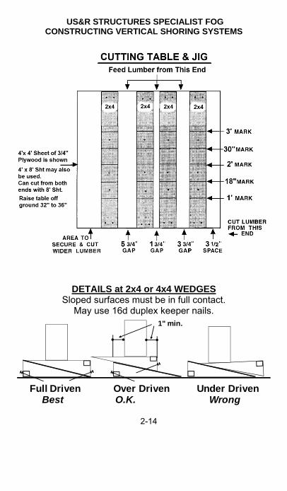
DETAILS at 2x4 or 4x4 WEDGES Sloped surfaces must be in full contact.
May use 16d duplex keeper nails.
Full Driven Over Driven Under DrivenBest O.K. Wrong
1" min.

US&R STRUCTURES SPECIALIST FOG CONSTRUCTING VERTICAL SHORING SYSTEMS
2-15
2
How to Construct Vertical Shores
T-Shore Page 2-16
Double T Shore 2-18
Vertical Shore – Multi Post 2-20
2-Post Vertical Shore 2-24
Laced Post Shore 2-28
2' x 4' Plywood Laced Post Shore 2-32
4' x 4' Plywood Laced Post Shore 2-35
Type 2 Sloped Floor Shore 2-38
Type 3 Sloped Post Shore 2-42
Cribbing 2-44

US&R STRUCTURES SPECIALIST FOG CONSTRUCTING VERTICAL SHORING SYSTEMS
2-16
T SPOT SHORE (Vertical/Class 1)
Design Load is 4,000lb –ONLY IF LOAD IS CENTERED
Maximum Height = 11 ft
Rapidly installed temporary shore, intended to be used only until a complete shoring system can be installed. It can become unstable if it is not centered under the load. Material List: Header and Sole One Wedge Set One Post 2 Full Gussets One Half Gusset

US&R STRUCTURES SPECIALIST FOG CONSTRUCTING VERTICAL SHORING SYSTEMS
2-17
2
HOW TO CONSTRUCT THE T SPOT SHORE 1. Determine where T Spot Shores should be built in order to
quickly reduce risk. (Prior to building more stable shores). 2. Determine height of area to be shored and remove
least amount of debris required to place the shore. 3. The 4x4 post should be 10'-3" max long, so that the total height
of the shore is not more than 11 feet. 4. Cut header and Sole to 3 feet long. 5. Cut post to proper height (remember to deduct header, sole and
wedge height when cutting post). 6. Prefabricate header to post. Toe-nail post to header and make square. Place and nail Full Gusset plate on one side. Flip shore over and place/nail another Full Gusset on other side. 7. Place T Shore in position, centered under the load. 8. Position header across (perpendicular to) the roof/floor joists
and position the post directly under a joist. 9. Slide sole plate under T and tap wedges into position. 10. Check for straightness & position directly under the load, and
then tighten the wedges. 11. Install bottom Half Gusset; nail 4-8d to post and to sole. 12. Note that a 2 x 4 x 18" cleat may be used, but the 3-16d nails to
post and sole may tend to split the cleat. Also the nailing of 16d causes more impact within the danger zone than for 8d nails.
13. Anchor the shore to floor above and sole to floor below, if practical.

US&R STRUCTURES SPECIALIST FOG CONSTRUCTING VERTICAL SHORING SYSTEMS
2-18
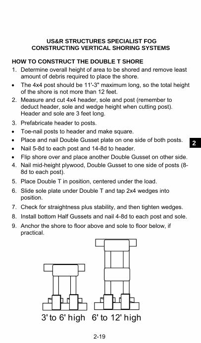
DOUBLE T SHORE (Vertical Class 2)
Design Load – based on shore height 16,000lb – 8 ft, 10,000lb – 10ft, 7,000lb – 12ft
This is the most stable spot shore, and much preferred to the marginally stable, T-Shore. Material List: Header and Sole 2 - Half Gussets 2 - Posts 2 - Wedge Sets 2 - Double Gussets One 12"x 24" ply mid- brace
US&R STRUCTURES SPECIALIST FOG CONSTRUCTING VERTICAL SHORING SYSTEMS
2-19
2
HOW TO CONSTRUCT THE DOUBLE T SHORE 1. Determine overall height of area to be shored and remove least
amount of debris required to place the shore. The 4x4 post should be 11'-3" maximum long, so the total height
of the shore is not more than 12 feet. 2. Measure and cut 4x4 header, sole and post (remember to
deduct header, sole and wedge height when cutting post). Header and sole are 3 feet long.
3. Prefabricate header to posts. Toe-nail posts to header and make square. Place and nail Double Gusset plate on one side of both posts. Nail 5-8d to each post and 14-8d to header. Flip shore over and place another Double Gusset on other side. 4. Nail mid-height plywood, Double Gusset to one side of posts (8-
8d to each post). 5. Place Double T in position, centered under the load. 6. Slide sole plate under Double T and tap 2x4 wedges into
position. 7. Check for straightness plus stability, and then tighten wedges. 8. Install bottom Half Gussets and nail 4-8d to each post and sole. 9. Anchor the shore to floor above and sole to floor below, if
practical.
3' to 6' high 6' to 12' high

US&R STRUCTURES SPECIALIST FOG CONSTRUCTING VERTICAL SHORING SYSTEMS
2-20
VERTICAL SHORE (Vertical Class 2)
4 – Post Vertical Shore (may have 3 or 5 posts)
Design Load 4 x 4 posts: Height = 8 feet 8,000 lb each post Height = 10 feet 5,000 lb each post Height = 12 feet 3,500 lb each post Design Load 6 x 6 posts: Height = 12 feet 20,000 lb each post Height = 16 feet 12,000 lb each post Height = 20 feet 7,500 lb each post
This shore normally is built in-place in the danger zone. Spot shores should precede the erection of this shore. Material List: 1 Header & 1 Sole 1 -Wedge Set each post 2 or more Posts 2 - 2x6 Diagonals ("X") Half Gussets – 5 for 3-post, 8 for 4-post, & 11 for 5-post Mid-brace (1 x 6 or 6" ply) see Additional Information

US&R STRUCTURES SPECIALIST FOG CONSTRUCTING VERTICAL SHORING SYSTEMS
2-21
2
HOW TO CONSTRUCT THE VERTICAL SHORE 1. Survey, install spot shores (if needed), and remove least
amount of debris required to place the shore. 2. Lay the sole plate on the floor or ground directly under and in
line where header will be installed. Sole plate should be level. Add 3-2x6x18" (foot) under sole at posts for soft soil conditions.
3. Measure and cut the posts to the proper height: Place the header on top of the sole plate. Place the end of the tape measure on top of the header at both
ends and at its middle, to find the distances to the bottom of the structure to be shored. After deducting for wedges, use smallest dimension for all posts. (assumes near-level conditions)
4. If possible, anchor the header to the area that is to be shored, square and in line with the sole plate. Secure it at the lowest point and shim the structural elements down to the header trying to keep it as level as possible.
5. Install the posts between the header and sole plate under each structural element to be supported. 4x4 Posts should be spaced 4 feet on center, maximum.
Install first two posts 12" from ends of header. Toe-nail each post to header and sole, and keep the posts in
line & plumb with header and sole plate. 6. Install a set of 2x4 wedges under each post, on top of Sole, and
tap them together simultaneously until the posts are tight. Toenail behind the wedges to secure them.
7. Attach the diagonal braces to each side of the vertical shore. Mid-point brace, when needed, should be installed prior to the
diagonal braces. The diag. braces should be long enough to span its entire length
and be attached to the sole plate and header and each post. If possible, diagonal braces should be installed in a "X" pattern
on opposite sides of the system. Vertical shoring systems which are very long may require
several sets of diagonal braces. 8. Attach half-gussets to one side of header to post, except where
diagonal braces attach. Add Half Gussets to each side of each post to sole plate, except where diagonal braces attach (then only one side). Nail with 8-8d. (Also see note 5. On page 2-9)

US&R STRUCTURES SPECIALIST FOG CONSTRUCTING VERTICAL SHORING SYSTEMS
2-22
ADDITIONAL INFORMATION 1. Maximum shore height for 4 x 4 posts: 12 feet. 2. Maximum shore height for 6 x 6 posts: 20 feet. 3. Posts: 4 x 4 minimum. Spacing for 4 x 4 posts: Maximum 4 feet on center. Spacing for 6 x 6 posts: Maximum 5 feet on center. 4. Header and Sole: Same size as posts in most cases. If supported slab is badly fractured concrete or masonry, larger
header should be designed. 5. Backing under Sole on Soil: Use 3-2x6x18" under sole centered on each post. May use 2 layers of 18"x18"x 3/4" plywood 6. Wedges: 2x4 for 4x4 posts & 2x6 or 3x6 for 6x6 posts. 7. Half Gussets at bottom: Each side to confine wedges, except where diagonal connects,
then only one side. 8. Half Gussets at Top: One side if header is the same size as post, except where
diagonal connects. Each side if header is taller than width. 9. Mid-Point Braces: Use 1x6 or 5/8" min plywood x 6", 5-8d to each post. Use if 4 x 4 posts are greater than 8 feet long. Use if 6 x 6 posts are greater than 12 feet long. 10. Diagonal X Braces: 2 x 6 each side of shore (place in X configuration and over mid-
brace, one side) 5-16d each end, to header, sole, and posts. May reduce nailing
to 3–16d at end posts if space is limited in order to reduce tendency to split post.
US&R STRUCTURES SPECIALIST FOG CONSTRUCTING VERTICAL SHORING SYSTEMS
2-23
2
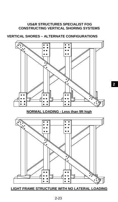
VERTICAL SHORES – ALTERNATE CONFIGURATIONS
NORMAL LOADING - Less than 9ft high
LIGHT FRAME STRUCTURE WITH NO LATERAL LOADING

US&R STRUCTURES SPECIALIST FOG CONSTRUCTING VERTICAL SHORING SYSTEMS
2-24
2-POST VERTICAL SHORE (Vertical/Class 2)
Design Load 4 x 4 posts: Height = 8 feet 16,000 lb Height = 10 feet 10,000 lb Height = 12 feet 7,000 lb
This shore is the same as one side of a laced post. It can be partly pre-fabricated, then assembled in danger area Material List: (See Additional Information) 1 - Header & 1 Sole 2 - Wedge Sets 2 - Posts 4 - Half Gussets
2 x Diagonal Bracing (Max height for shore w/ 4x4 posts is 12ft)
1 for shore up to 6 feet high 2 for shore from 6ft to11 ft 3 for shore from 11ft to 17 ft 4 for shore from 17ft to 20 ft
1x Horizontal Bracing 1 for shore from 6ft to11 ft 2 for shore from 11ft to 17 ft 3 for shore from 17ft to 20 ft
US&R STRUCTURES SPECIALIST FOG CONSTRUCTING VERTICAL SHORING SYSTEMS
2-25
2
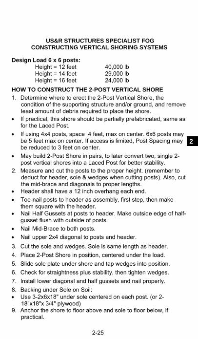
Design Load 6 x 6 posts: Height = 12 feet 40,000 lb Height = 14 feet 29,000 lb Height = 16 feet 24,000 lb HOW TO CONSTRUCT THE 2-POST VERTICAL SHORE 1. Determine where to erect the 2-Post Vertical Shore, the
condition of the supporting structure and/or ground, and remove least amount of debris required to place the shore.
If practical, this shore should be partially prefabricated, same as for the Laced Post.
If using 4x4 posts, space 4 feet, max on center. 6x6 posts may be 5 feet max on center. If access is limited, Post Spacing may be reduced to 3 feet on center.
May build 2-Post Shore in pairs, to later convert two, single 2-post vertical shores into a Laced Post for better stability.
2. Measure and cut the posts to the proper height. (remember to deduct for header, sole & wedges when cutting posts). Also, cut the mid-brace and diagonals to proper lengths.
Header shall have a 12 inch overhang each end. Toe-nail posts to header as assembly, first step, then make
them square with the header. Nail Half Gussets at posts to header. Make outside edge of half-
gusset flush with outside of posts. Nail Mid-Brace to both posts. Nail upper 2x4 diagonal to posts and header. 3. Cut the sole and wedges. Sole is same length as header. 4. Place 2-Post Shore in position, centered under the load. 5. Slide sole plate under shore and tap wedges into position. 6. Check for straightness plus stability, then tighten wedges. 7. Install lower diagonal and half gussets and nail properly. 8. Backing under Sole on Soil: Use 3-2x6x18" under sole centered on each post. (or 2-
18"x18"x 3/4" plywood) 9. Anchor the shore to floor above and sole to floor below, if
practical.

US&R STRUCTURES SPECIALIST FOG CONSTRUCTING VERTICAL SHORING SYSTEMS
2-26
ADDITIONAL INFORMATION – 2-Post Shore 1. Maximum shore height for 4 x 4 posts: 12 feet. 2. Maximum shore height for 6 x 6 posts: 20 feet. 3. Posts: 4 x 4 or 6 x 6. Spacing for 4 x 4 posts: Maximum 4 feet on center. Spacing for 6 x 6 posts: Maximum 5 feet on center. 4. Header and Sole: Same size as posts in most cases. If supported slab is badly fractured concrete or masonry, one
needs to engineer larger sized header. 5. Half Gussets at Bottom: Each side to confine wedges, except where diagonal connects,
then only one side. 6. Half Gussets at Top: One side if header same size as post, except where diagonal
connects. Each side if header is taller than width. 7. Diagonal Braces: (Max. length is 7'-6") 2 x 4 for 4 x 4 posts. 2 x 6 for 6 x 6 posts. 8. Mid-Point Braces: (see below for configurations). 2 x 4 for 4 x 4 posts & 2 x 6 for 6 x 6 posts.
4' to 6' high 6' to 11' 11' to 17' 17' to 20' high Note: Maximum height using 4 x 4 posts is 12 feet

US&R STRUCTURES SPECIALIST FOG CONSTRUCTING VERTICAL SHORING SYSTEMS
2-27
2
This Page Left Blank

US&R STRUCTURES SPECIALIST FOG CONSTRUCTING VERTICAL SHORING SYSTEMS
2-28
LACED POST SHORE (Vertical/Class 3)
DESIGN LOAD: 4x4 Posts = 32,000lb 6x6 Posts = 80,000lb
High Capacity four post system. It is constructed similar to a pair of 2-post vertical shores, but laced together. Material List: (See ADDITIONAL INFORMATION) 2 each Header & Sole 8 Half gussets 4 Posts 4 Wedge Sets
Diagonal and Horizontal Bracing (number for each)
4 for shore up to 6 feet high 8 for shore from 6ft to11 ft 12 for shore from 11ft to 17 ft 16 for shore from 17ft to 20 ft

US&R STRUCTURES SPECIALIST FOG CONSTRUCTING VERTICAL SHORING SYSTEMS
2-29
2
HOW TO CONSTRUCT THE LACED POST SHORE 1. Survey, install spot shores (if needed), and remove the least
amount of debris required to place the shore. 2. Determine the length and height of the shore. Cut the header and sole plates 24 inches longer than width of
the shore to allow for 12 inch overhangs. Cut the posts to allow for header, sole and wedges. 3. Nail posts to header with toenails and keep them square. Check by comparing diagonal, full-height distances (outside top-
right to outside bottom-left, should be same as outside top-left to outside-bottom right).
If posts are not straight, set both with bow-out. Nail a half-gusset to one post/header joint, then nail the
midpoint brace (braces) in position. Re-check diagonal measurement and pull-in any bow-out.
4. Measure and install the top diagonal, so it overlaps and ties into the header. Use proper nail pattern.
5. Measure and install mid-diagonals, if required by height. 6. Fabricate the second section, using first as template. 7. Have the horizontal tie-in braces precut for ease of assembly. 8. Bring both sections and the sole plates into position and place
the prefabricated units on top of the sole plates. 9. Install wedges under each post, and check post spacing. 10. Nail the horizontal braces to the two sections on both sides.
Start with the lowest mid-brace and work up. 11. Measure for all the diagonals, and configure in K or parallel
layout, as best works for the situation. Avoid intersecting too many diagonals on a post at a single
location. 12. At the sole plate, make sure the bottom diagonal extends past
the post and nails into the sole plate. Place a half-gusset plate onto the opposite side of this post and
to each side of the other posts at the base. (Outside edge flush) 13. Anchor the shore to the ceiling and floor, if practical. 14. Make sure all wedges are snug and the proper nail patterns
were used.

US&R STRUCTURES SPECIALIST FOG CONSTRUCTING VERTICAL SHORING SYSTEMS
2-30
ADDITIONAL INFORMATION – LACED POST SHORE 1. Maximum shore height for 4 x 4 posts: 17 feet. 2. Maximum shore height for 6 x 6 posts: 20 feet. 3. Posts: Same spacing each way. 4 x 4 posts: Maximum 4 feet on center. 6 x 6 posts: Maximum 5 feet on center. 4. Header and Sole: same size as posts. 5. Half Gussets at Top: One side (exterior) where no diagonal. 6. Half Gussets at Bottom: One side (interior) at diagonals. Each side where no diagonals. 7. Diagonal Braces: 2 x 4 for 4 x 4 posts. 2 x 6 for 6 x 6 posts. 8. Mid-Point Braces and Horizontal Struts: 2 x 4, 2 x 6 in
configuration shown below. (equally spaced)
Note: Maximum height using 4 x 4 posts is 17 feet
4' to 6' high 6' to 11' 11' to 17' 17' to 20' high

US&R STRUCTURES SPECIALIST FOG CONSTRUCTING VERTICAL SHORING SYSTEMS
2-31
2
MOST COMMON CONFIGURATION – LACED POST SHORE
DESIGN LOAD: 4x4 Posts = 32,000lb 6x6 Posts = 80,000lb
Material List: (for 6ft to 11ft high) 2 each Header & Sole 8 Half gussets 4 Posts 4 Wedge Sets Diagonal and Horizontal Bracing (number for each)
4 for shore up to 6 feet high 8 for shore from 6ft to11 ft

US&R STRUCTURES SPECIALIST FOG CONSTRUCTING VERTICAL SHORING SYSTEMS
2-32
2' x4' PLYWOOD LACED POST (Vertical/Class 3)
2'-0
" max
.2'
-0"
Design Load: 4 x 4 posts =32,000 lb 6 x 6 posts = 80,000 lb
High Capacity four post system, similar to Std. Laced Post, but laced together with plywood, & lighter /faster. Material List: 2- each, Header & Sole 8- Half gussets, 2 Dbl gussets 4 - Posts 4 - Wedge Sets 8" x 48" top/bottom plywood braces Use 4 for all heights
24" x 24" mid-braces & 24" x 48" mid-braces
Use 2 up to 9ft Use 4 from 9ft to 13ft

US&R STRUCTURES SPECIALIST FOG CONSTRUCTING VERTICAL SHORING SYSTEMS
2-33
2
HOW TO CONSTRUCT THE 2' X 4' PLY LACED POST 1. Survey, install spot shores (if needed), and remove least
amount of debris required to place the shore. 2. Determine the height of the shore. Cut the header and sole plates to 4 feet in length. (12" O.hangs) 3. Nail posts to header with toenails and keep them square. Check by comparing diagonal, full-height distances (outside top-
right to outside bottom-left, should be same as outside top-left to outside-bottom right).
If posts are not straight, set both with bow-out. Nail a double gusset: header to both posts. Nail the plywood mid braces in position. Re-check diagonal
measurement, & if posts bow-out, pull them in with the plywood braces. Use proper nail pattern.
4. Fabricate the second section, using first as template. 5. Have the plywood braces precut for ease of assembly. 6. Bring both sections and the sole plates into position and place
the prefabricated units on top of the sole plates. Make sure that the prefabricated units are spaced 4 foot out to
out, to allow for 4 ft plywood braces. 7. Install wedges under each post, and check post spacing. 8. Nail the plywood braces to the two sections on both sides (start
with lower ones and climb up). 9. Nail the top and bottom plywood braces in place. Place a half-gusset plate on each side of each post to sole,
with outside edge of gusset flush w/ post outside face. 10. Anchor the shore to the ceiling and floor, if practical. 11. Make sure all wedges are snug and the proper nail patterns
were used.

US&R STRUCTURES SPECIALIST FOG CONSTRUCTING VERTICAL SHORING SYSTEMS
2-34
ADDITIONAL INFORMATION - 2'x4' Plywood Laced Post 1. Maximum shore height for 4 x 4 posts: 13 feet. 2. Maximum shore height for 6 x 6 posts: 13 feet. 3. Posts: 4 x 4 and 6 x 6 are spaced the same. Space 2 foot x 4 foot out to out. 4. Header and Sole: same size as posts. 5. Double gusset on outside at top, header to both posts. 6. Half Gussets, each side at each post at bottom. 7. Plywood top and bottom braces : 8" x 48" plywood. 8. Plywood middle braces: 24" x 24", 24" x 48" plywood. Distance from top or bottom of shore to nearest middle brace for
9 ft to 13 ft heights shall be 2'-0" maximum. 9. All plywood may be 5/8" or 3/4" (or OSB for dry conditions). 10. Plywood bracing configuration for various heights is shown
below:
4' to 9' high 9' to 13' high

US&R STRUCTURES SPECIALIST FOG CONSTRUCTING VERTICAL SHORING SYSTEMS
2-35
2
4' x4' PLYWOOD LACED POST (Vertical/Class 3)
2'-0
" max
.2'
-0"
Design Load: 4 x 4 posts =32,000 lb 6 x 6 posts = 80,000 lb
High Capacity four post system, similar to standard Laced Post, but braced together with plywood. Material List: 2- each Header & Sole 12 - Half gussets 4 – Posts 4 - Wedge Sets 8" x 48" top/bottom braces Use 4 for all heights
24" x 48" ply mid-braces Use 4 up to 9ft Use 8 from 9ft to 13ft Use 12 from 13ft to 17ft

US&R STRUCTURES SPECIALIST FOG CONSTRUCTING VERTICAL SHORING SYSTEMS
2-36
HOW TO CONSTRUCT THE 4' X 4' PLY LACED POST 1. Survey, install spot shores (if needed), and remove least
amount of debris required to place the shore. 2. Determine the height and width of the shore. Cut the header and sole plates to 6 feet in length.(12" O-hangs) 3. Nail posts to header with toenails and keep them square. Check by comparing diagonal, full-height distances (outside top-
right to outside bottom-left, should be same as outside top-left to outside-bottom right).
If posts are not straight, set both with bow-out. Nail a half gusset from header to both posts. Nail the plywood mid-braces in position. Re-check diagonal
measurement, & if posts bow-out, pull them in with the plywood braces. Use proper nail pattern.
4. Fabricate the second section, using first as template. 5. Have the plywood braces precut for ease of assembly. 6. Bring both sections and the sole plates into position and place
the prefabricated units on top of the sole plates. Make sure that the prefabricated units are spaced 4 foot out to
out, to allow for 4 ft plywood braces. 7. Install wedges under each post, and check post spacing. 8. Nail the plywood braces to the two sections on both sides (start
with lower ones and climb up). 9. Nail the top and bottom plywood braces in place. Place a half-gusset plate on each side of each post to sole,
with outside edge of gusset flush w/ post outside face. 10. Anchor the shore to the ceiling and floor, if practical. 11. Make sure all wedges are snug and the proper nail patterns
were used.

US&R STRUCTURES SPECIALIST FOG CONSTRUCTING VERTICAL SHORING SYSTEMS
2-37
2
ADDITIONAL INFORMATION – 4'x4' Plywood Laced Post 1. Maximum shore height for 4 x 4 posts: 17 feet. 2. Maximum shore height for 6 x 6 posts: 17 feet. 3. Posts: 4 x 4 and 6 x 6 are spaced the same.
Space 4 foot x 4 foot out to out (to match plywood). 4. Header and Sole: same size as posts. 5. Half Gusset on outside at top for each post. 6. Half Gussets each side each post at bottom. 7. Plywood top and bottom braces : 8" x 48" plywood. 8. Plywood middle braces: 24" x 48" plywood. Distance from top or bottom of shore to nearest middle brace for
9 ft to 17 ft heights shall be 2'-0" maximum. There shall be a middle brace placed, centered at the half-
height of the shore for 13 ft to 17 ft heights. 9. All plywood may be 5/8" or 3/4" (or OSB for dry conditions). 10. Plywood bracing configuration for various heights is shown
below:
4' to 9' high 9' to 13' 13' to 17' high

US&R STRUCTURES SPECIALIST FOG CONSTRUCTING VERTICAL SHORING SYSTEMS
2-38
SLOPED FLOOR SHORE–TYPE 2 (Vertical/Class 3)
Foot only at soil bearing
Design Load (depends on slope): 4x4 Posts = 24,000lb Max. (Consult Structures Specialist) 6x6 Posts = 60,000lb Max.
Built in pairs similar to a laced post shore. Used to support damaged and sloped, concrete floors that are still connected to remaining structure. (hinging slabs) Material List: (for a pair of shores) 2 - Headers & Soles 8 - Half Gussets 4 Posts 4- 2x cleats x 18" long, 11-16d 4 - Diagonal Braces (1 each side each shore) Anchor Sole w/ 4-1/2 x 8 drill-in anchors into concrete or Sole Anchor from 4 x 4 / 6 x 6 w/ 4 - 1"dia. X 36"pickets. Bracing between shores: (see graphic under Additional Information)

US&R STRUCTURES SPECIALIST FOG CONSTRUCTING VERTICAL SHORING SYSTEMS
2-39
2
HOW TO CONSTRUCT SLOPED FLOOR SHORE–TYPE 2
(May be constructed on Paving or on Soil) 1. Survey, install spot shores (if needed), and remove least
amount of debris required to place the shore. 2. Determine length and width of shore and post locations. Header overhang is 12 inch maximum. Sole must extend 30"
longer from front of longer post, to allow for cleat & anchors. Shore is built as pair of 2-post sections, like laced post. The 2 sections should be placed from 4 ft to 8 ft on center 3. Cut and install the headers and soles. If shore is installed on soil, the standard 18" x 18" foot should be
placed under sole at each post. (3-2x6x18" or 2-layers 3/4" ply) 4. Measure and install the two posts at each section. Make angle and return cuts similar to rakers. Toe-nail posts to headers, and drive bottoms of posts tight and
toe-nail.(no wedges, since they get in the way of the braces) 5. Install bottom cleats tight against each post. 6. Anchor the sole plates, as follows: Anchor sole using drilled-in anchors or 1"dia. X 36" rebar to
anchor to concrete or paving, based on Structures Spec. recommendations. (2 minimum per 2-post section).
See page 3-9 for alternate Sole Plate Anchor system. 7. Measure for diagonal braces inside and outside each section. 8. Install 2x6 diagonal braces in position and nail to posts, headers
and sole plates.(may use 3-16d into posts to limit splitting) Cleat/Half Gusset plate the opposite side of the posts, top and
bottom, using the 4 and 4 nail pattern. Need to place Half Gussets to clear the horizontal and diagonal
braces (to be installed next), or use 2x cleats instead of gussets. 9. Tie the two sections together, same as in Laced Posts. (See
Additional Information for alternatives). Ties are placed between posts at the taller and the shorter ends
of each shore section. Use a wide piece of 5/8" or 3/4" plywood (12" to 24" wide) if
short end of shore is too short to fit X braces. The plywood or 2x6 bracing may be installed on the inside of
the shorter posts, if that is easier. 10. Attach to the floor and ceiling. (If possible).

US&R STRUCTURES SPECIALIST FOG CONSTRUCTING VERTICAL SHORING SYSTEMS
2-40
ADDITIONAL INFORMATION – Type 2 & 3 Sloped Fl Shores 1. Posts: Spacing for 4 x 4 posts: Maximum 4 feet on center. Spacing for 6 x 6 posts: Maximum 5 feet on center. Spacing between shores as pairs: 4 ft to 8 ft on center. 2. Header and Sole: same size as posts. 3. Half Gussets: on opposite sides of diagonals, top & bottom. 4. Diagonal Braces: (2 x 6 on each side or shore) 5. Soil Support: (18" x 18" foot at soil bearings only) 3 - 2 x 6 x 18" (flat) or 2 - 18" x 18" x 3/4" plywood layers,
placed under each post. 6. May directly anchor sole with 2 – 1/2" x 8 ½" wedge anchors or
1/2" x 8" rebar or smooth bar, drill-in anchors, through sole into concrete floor.
7. Alternate Sole Anchor: see Section 3 for details. 4 x 4 or 6 x 6 (preferred) x spacing of shores + 4ft. 2 x 4 or 4 x 4 wedges at each shore. 4 or more 1" diameter x 36" long pickets. 8. Bracing/lacing between shores: (all are 2x6). Built in Pairs and Braced/laced together, or, Built in groups (4 feet min to 8 feet max on center). Horizontals & Diagonals are 2 x 6 ( 2 - 2 x 4 alternate). Horizontal Plywood Braces: 5/8" or 3/4" x 12" (min). where
height is 3 ft or less, 11-8d each end.
Up to 5ft o.c. 5ft to 8ft o.c. 3ft or less highBracing between Shores

US&R STRUCTURES SPECIALIST FOG CONSTRUCTING VERTICAL SHORING SYSTEMS
2-41
2
This Page Left Blank

US&R STRUCTURES SPECIALIST FOG CONSTRUCTING VERTICAL SHORING SYSTEMS
2-42
SLOPED FLOOR SHORE–Type 3 (Vertical/Class 3)
Foot only at soil bearing Design Load (depends on slope): 4x4 Posts = 24,000lb Max. (Consult Structures Specialist) 6x6 Posts = 60,000lb Max.
Built in pairs similar to Type 2 Sloped Floor Shore. Support concrete floors that are not connected to remaining structure and may slide. Material List: (for a pair of shores) 2 - Headers & Soles 8 - Half Gussets 4 – Posts 4- 2x cleats x 18", 11-16d 4 – Wedge Sets (Optional) 4 – 1/2" drill-in anchors 4 - Diagonal Braces (1 each side each shore) Sole Anchor from 4 x 4 / 6 x 6 w/ 4 - 1"dia. X 36"pickets. Bracing between shores: See bottom of page 2-40

US&R STRUCTURES SPECIALIST FOG CONSTRUCTING VERTICAL SHORING SYSTEMS
2-43
2
HOW TO CONSTRUCT SLOPED FLOOR SHORE–TYPE 3 1. Survey, install spot shores (if needed), and remove debris. 2. Determine length and width of shore and post locations. Shore is built as pair of 2-post sections, like laced post. The 2 sections should be placed from 4 ft to 8 ft on center Header overhang is 12 inches on shorter end, but should be
increased to 30" at higher end for cleat and anchors. Sole plates should extend 12 inches beyond each post.
Install headers and sole plates, and anchor header. If shore is installed on soil, the standard 18" x 18" foot should be
placed under the sole at each post. Prepare to install one,18 inch cleat, for each post on underside
of header (pre-install as many as possible cleats on header w/ 11-16d nails, to reduce nailing in Collapse Zone).
3. Measure, angle/return cut, and install the two posts for each section; toe-nail to header, then drive posts tight and plumb. Wedges are optional, but may be used as with vertical shores.
4. Make sure posts are plumb, and install remaining 18" top cleats. 5. Attached header to ceiling/slab bottom with 2 - 1/2" x 8 ½"
wedge anch., or rebar/smooth bar x 8" min. (embed at least 4") 6. Anchor the sole plate, and re-check/re-drive the post tight. 7. Measure for the diag. braces inside/outside of each section. 8. Install 2x6 diagonal braces in position and nail to posts, header,
and sole plate. (may use 3-16d into posts to limit splitting) Place Half-Gusset plate the opposite side of the posts, top and
bottom, and complete gusset nailing – 4 & 4, 8d. Note: Half-Gussets may be installed with posts – partly nailed.
Need to place Half-Gussets to clear the horizontal and diagonal braces (to be installed next) -
9. Tie the two sections together, same as in Laced Posts. (See Additional Information for alternatives).
Ties are placed between posts at the taller and the shorter ends of each shore section.
Use a wide piece of 5/8" or 3/4" plywood (12" to 24" wide) if short end of shore is too short to fit X braces.
The plywood or 2x6 bracing may be installed on the inside of the shorter posts, if that is easier.
10. Attached to the floor and ceiling. (If possible).

US&R STRUCTURES SPECIALIST FOG CONSTRUCTING VERTICAL SHORING SYSTEMS
2-44
CRIBBING (Vertical/Class 3)
Cribbing is an easily adjustable shore for height and width dimensions. Height must be limited due to large amount of deflection due to crushing, especially when different crushing rates occur at different bearings. Material List: Depends on height, number of pieces per layer and the height of each piece. See configurations below.

US&R STRUCTURES SPECIALIST FOG CONSTRUCTING VERTICAL SHORING SYSTEMS
2-45
2
HOW TO CONSTRUCT CRIBBING 1. Survey, install spot shores (if needed), and remove debris. 2. Determine where Spot Shores should be built in order to quickly
reduce risk. 3. Determine overall height of area to be shored and remove least
amount of debris required to place shore. 4. Determine the desired width dimensions of the crib. 5. Determine the size of the members to be used, and the
configuration of the crib layers. Use 6x6 members if crib needs to be more than 4 ft high. Note that the 3-member x 3-member configuration is more than
2 times as strong as 2-member x 2-member. 6. Decide if the first layer needs to be a solid layer, depending on
the type of bearing material. (soil or other surface softer than a concrete slab.
If the supporting surface is concrete, make sure that it has the required stiffness and capacity, and there is not a basement story below.
7. Carefully slide the members in for each layer, and keep the crib aligned and as square as possible.
8. When the crib reaches required height, add shims to make sure that all intersections of crib members are in solid contact with the supported structure.
9. Attach the crib to the supporting surface (or confine its movement), if practical.
10. Where vibration and aftershocks may occur, interconnect the crib layers with 3/8" min x 16" long plywood strips that are 1.5 times as high as the cribbing members.
The plywood strips need to be placed on all 4 sides of the crib. Nail plywood strips at top and bottom edges to crib members
with 8d at 3 inches on center as shown below:

US&R STRUCTURES SPECIALIST FOG CONSTRUCTING VERTICAL SHORING SYSTEMS
2-46
ADDITIONAL INFORMATION - Cribbing 1. Height: Maximum = 3 x shortest width.
Recommended Max. height for 4x4 systems is 4 feet.
Recommended Max. height for 6x6 systems is 6 feet.
2. Solid bottom layer for soil or asphalt applications.
3. Overlap corners by at least 4 inches.
4. Design Load Basis –
Cross-grain bearing of the wood (varies from 200 psi to 1,000 psi – Use 500 psi for Douglas Fir and Southern Pine).
Load per bearing point.
Number of Bearing Points.
Design Load Formula: L = A x N x P L = Load A = Area of single bearing point (sq. in.) N = Number of Bearing Points P = Allowable bearing pressure (psi)
Design Load for 4x4 Douglas Fir & Southern Pine. 2 member x 2 member system = 24,000lbs 3 member x 3 member system = 54,000lbs
Design Load for 6x6 Douglas Fir & Southern Pine. 2 member x 2 member system = 60,000lbs 3 member x 3 member system = 135,000lbs

US&R STRUCTURES SPECIALIST FOG CONSTRUCTING VERTICAL SHORING SYSTEMS
2-47
2
CRIBBING at SLOPED FLOOR (Vertical/Class 3)
Cribbing can be built under a concrete sloped floor . Wedges and shims should be added to each layer in order to achieve the slope gradually. The max. Slope should be 30 deg off the horizontal. The max. height should be 4ft when using 4x4 lumber, and 6ft for 6x6. Material List: Depends on height, number of pieces per layer and the height of each piece. See configurations below.

US&R STRUCTURES SPECIALIST FOG CONSTRUCTING VERTICAL SHORING SYSTEMS
2-48
WINDOW AND DOOR SHORE (Vertical/Class 2)
Design Load: 4x4 Header = 2,000 lb 6x6 = 6000lb
This shore is used in URM buildings to support loose masonry over openings. May be used in other building types where door /window headers are damaged. Material List: Header and Sole 4 Wedge Sets 2 Posts 1 Half Gusset 3 Cleats Shims as required Diagonal Braces 2 - 2 x 4 (if not used for access)

US&R STRUCTURES SPECIALIST FOG CONSTRUCTING VERTICAL SHORING SYSTEMS
2-49
2
HOW TO CONSTRUCT THE WINDOW/DOOR SHORE 1. Survey, remove finishes (if required), and remove debris. 2. Measure and cut the sole plate and header to the proper length
deducting the width of the wedges to be used. 3. Make header 1" deep for every foot of opening; 4x4 min. 4. Have StS design header for opening over 4ft wide. 5. Measure and cut the posts to the proper height. Place the header on top of the sole plate. To determine post height, place the end of the tape measure on
top of the header where the posts are to be installed, slide the tape up to the bottom of the structural element to be shored deducting the thickness of the wedges to be used. (Use the shorter of the two measurements).
6. Install the sole with a set of wedges at one end and tap them together simultaneously until the sole is tight.
7. The sole should be as level as possible: use shims as necessary under the sole plate.
8. Install the header with a set of wedges at the opposite end of the sole and tap them together until the header is tight.
9. The header should be as level as possible; use shims as necessary above the header.
10. Install the posts between the header and sole, and against the sides of the opening.
11. Install the first post under the wedge side of the header to prevent movement if the header wedges loosen.
12. Keep posts in line and plumb with header and sole. 13. Install a wedge set under each post, on top of the sole. Wedges
are then tightened to lock shore in place. 14. Attach cleat and half-gusset to at least one side of the header
and posts and nail in place. 15. Confine the wedges by placing a cleat against the inside face of
each post at the bottom and nail them in place with 3-16d nails to each post and 2-16d toe nails to the sole.
May use duplex nails for future adjustment of the wedges.

US&R STRUCTURES SPECIALIST FOG CONSTRUCTING VERTICAL SHORING SYSTEMS
2-50
PRE-CONSTRUCTED SHORING SYSTEMS
1. Window/Door Shores may be pre-constructed as shown in Prefabricated Window/Door Shore (next page). They should be made at least 1 ½" less than opening in
each direction, and then tightened with wedges at one side and bottom + shims as required. If header is badly damaged, great care should be
taken during installation of the shoring and shims. It shims are needed at the top, one should try to
eliminate the wedges at the bottom. Pre-constructed Window & Door Shores will not be
practical in racked or otherwise deformed openings. For large openings, pre-constructed shores may be too
heavy to carry up to locations above ground floor.
Main advantage is to allow pre-construction a safe distance from the dangerous wall or collapse zone.
2. Pneumatic Shores, with a minimum of two shores with wood or metal rail header. (see page following Alt Window Shore)
Metal ends should be nailed to header and sole. The manufacturers sell clamp fittings that allow for nailed
2x6 X bracing to be installed.
Pneumatic shores are best used as temporary shores. Some manufacturers provide a Header Rail that may be
per-assembled with two or more struts to provide a pre-constructed, vertical shore.
WARNING – The use of Air Pressure to raise these shores into place has caused accidents. Air Pressure should be limited to 50 PSI, and all Pneumatic Shores should be hand tightened – to snug condition.
See Strut Tables in Sect 7 of StS FOG for recommended Strut Loading based on height (length).

US&R STRUCTURES SPECIALIST FOG CONSTRUCTING VERTICAL SHORING SYSTEMS
2-51
2
PREFABRICATED WINDOW/DOOR SHORE
Design Load: 4x4 Header = 2,000 lb 6x6 = 6000lb
Alternate to built in-place Window/Door Shore. Main advantage is to allow pre-construction a safe distance from the collapse zone. Also the shore can be reused. Material List: Header and Sole 4 - Wedge Sets 2 - Posts 8- Half Gussets

US&R STRUCTURES SPECIALIST FOG CONSTRUCTING VERTICAL SHORING SYSTEMS
2-52
HOW TO CONSTRUCT THE PREFAB. WINDOW/DOOR SHORE 1. Survey, remove finishes (if required), and remove debris. 2. Measure opening and check to see if it is square or racked. 3. Measure and cut header and sole 1 ½ inches less than opening
width to allow for wedges. 4. Measure and cut post. Length should allow for the thickness of
sole and header and an additional 1 ½ inches for wedges. 5. Place one Half Gusset from each post to header and to sole.
Nail each half gusset with 8-8d. 6. Turn shore over and place a half gusset on opposite side of
previously installed gussets. 7. Carry shore to opening and install one wedge set under the sole
at each end. 8. Install one wedge set between header and door/window side
edge. 9. Install one wedge set between sole and door/window side edge. 10. Place shims between top of header and top edge of opening at
mid-span and as required for adequate support.

US&R STRUCTURES SPECIALIST FOG CONSTRUCTING VERTICAL SHORING SYSTEMS
2-53
2
VERTICAL SHORING USING PNEUMATIC STRUTS
Pneumatic Strut Manufacturers have developed special configurations that may be used to construct Vertical Shores. See following pages for configurations. 1. Struts may be configured as T, Dbl-T, Vertical 2-post and
Multi-Post Shores. In addition there are special configurations such as: 3-Post Column, Sloped Floor Shore, Window/Door Shore, and Laced Post Shore.
2. Wood headers are used in most cases, and Wood Soles are needed when the load needs to be spread-out on the structure that is supporting the shore.
3. The standard Pneumatic Shore Base Plates may be used when shore in bearing on an adequate concrete slab. Consult qualified Structures Specialist.
4. The strength of these shores may be determined by knowing the height and number of struts that are used. The basic values are shown in tables in Section 7. Consult qualified Structures Specialist, since other factors such as header strength may govern the shore capacity.
5. Low pressure air (50psi max) may be used to extend the struts, but care must be taken to not impact the structure.
6. Use hand tightening to snug-up all joints.

US&R STRUCTURES SPECIALIST FOG CONSTRUCTING VERTICAL SHORING SYSTEMS
2-54
PNEUMATIC T-SHORE Temporary, Spot Shore that is relatively unstable. The load must be centered on the post. Capacity should not be assumed to be more than 1,000lb DBL-T SHORE Uses 2 – Struts with header and sole. It may be used as a Temporary, Spot Shore, but is more stable than T Shore Shore capacity may be based on the length of the struts as given in the table in Section 7.

US&R STRUCTURES SPECIALIST FOG CONSTRUCTING VERTICAL SHORING SYSTEMS
2-55
2
VERTICAL SHORE Use 3 or more struts with header, sole and X-bracing as shown. Capacity may be based on the length of the struts as given in the table in Sect 7. 2-POST VERTICAL SHORE Use 2- vertical struts, plus a diagonal strut that must be configured to resist both tension & compression

US&R STRUCTURES SPECIALIST FOG CONSTRUCTING VERTICAL SHORING SYSTEMS
2-56
3-STRUT COLUMN Uses 3 pneumatic struts with specially manufactured cap and foot. Cap and Base may need wood cribbing or multi-layers of plywood to spread the load. Shore capacity may be based on the length of the struts as given in the table in Section 7.
SLOPED FLOOR SHORE Uses a minimum of 2-pneumatic struts, and is a Temporary, Spot Shore. Capacity is limited, and is only viable if the supported slab remains connected to the structure.
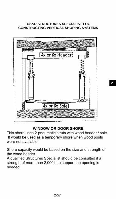
US&R STRUCTURES SPECIALIST FOG CONSTRUCTING VERTICAL SHORING SYSTEMS
2-57
2
WINDOW OR DOOR SHORE This shore uses 2-pneumatic struts with wood header / sole. It would be used as a temporary shore when wood posts were not available. Shore capacity would be based on the size and strength of the wood header. A qualified Structures Specialist should be consulted if a strength of more than 2,000lb to support the opening is needed.

US&R STRUCTURES SPECIALIST FOG CONSTRUCTING VERTICAL SHORING SYSTEMS
2-58
LACED POST SHORE This shore uses 4-pneumatic struts with wood header. Each strut will need a metal, manufactured base. This shore should only be used when it is specified and supervised by a qualified Structures Specialist, and he or she should determine the capacity. All horizontal and diagonal members must be special struts that are capable of resisting tension and compression.

US&R STRUCTURES SPECIALIST FOG CONSTRUCTING LATERAL SHORING SYSTEMS
3-1
3
INTRODUCTION to SECTION 3 This section contains General Information, Graphics and Detailed Explanations of how to construct FEMA Raker and Horizontal Shoring – arranged as follows: Raker Shore – General Information
Types of Rakers page 3-2 Raker Cleats & Gussets 3-3 How to determine Raker Angle & Length 3-4 Raker Shore Bracing 3-6 Backing for Rakers at Special Walls, & Raker Splice 3-8 Trough Base and Sole Anchor 3-9 Use of Framing Square 3-10
How to construct Raker Shores 3-11 Flying Raker – Spot Shore 3-12 Raker with backing for Wood or Masonry Walls 3-15 Solid Sole Raker 3-16 Split Sole Raker 3-20
How to construct Horizontal Shores 3-24 Tiebacks and Alternate Raker Systems 3-27 Pneumatic Strut Systems: Horizontal & Raker Shores 3-29 Note: See Sect 2 for Size-up, and General Information and
Shoring Details.

US&R STRUCTURES SPECIALIST FOR CONSTRUCTING LATERAL SHORING SYSTEMS
3-2
RAKER SHORES: GENERAL INFORMATION
Description: Used in search and rescue incidents to stabilize leaning and/or damaged walls. There are 3 types: Flying, Solid Sole and Split Sole. All have unique characteristics. Material List: See each individual system.
Raker: Flying (Friction) Temporary, spot rakers when debris are piled next to the base of the wall.
Raker: Solid Sole (Full Triangle) Most desirable rakers, are normally built in groups of 2 or more as Class 3 Systems with lateral bracing.
Raker: Split Sole Intended to be used when there is soil adjacent to the wall, and/or there is a limited amount of debris next to the wall. Build as Class 3 Systems.

US&R STRUCTURES SPECIALIST FOG CONSTRUCTING LATERAL SHORING SYSTEMS
3-3
3
RAKER SHORES: GENERAL INFORMATION 1. Raker Shores may be built in a progression, starting with Flying
Raker, to stabilize the wall, followed by a group of Full Triangle Rakers (Since Full Triangle Rakers are mostly pre-fabricated, they may be installed without first installing Flying Rakers).
2. Top Cleat for 4 x 4 Raker. 24 inches with 14 – 16d nails for 45 degree rakers.
2" 5" 5"o.c.
30 inches with 20 - 16d nails for 60 degree rakers.
3. Top Cleat for 6 x 6 Raker: 24 inches with 20 – 16d nails for 45 degree rakers. 30 inches with 29 - 16d nails for 60 degree rakers. 4. Bottom Cleat: 24 inches with 14 – 16d nails for 4 x 4 rakers. 24 inches with 20 - 16d nails for 6 x 6 rakers. 5. Plywood gussets: 5/8" or 3/4" (OSB if not wet area).
12"
12" All 8d nails
Top of Raker Bottom of Raker Rear of Raker 6. Sole Anchor: All rakers need a Sole Anchor. (shown later)
5" 5" 5"o.c.

US&R STRUCTURES SPECIALIST FOR CONSTRUCTING LATERAL SHORING SYSTEMS
3-4
DETERMINING RAKER SHORE ANGLE & LENGTH 1. Any angle between 30 and 60 degrees will work effectively. The lower the angle, the more efficient the raker will be. 2. The two most common angles used are 45 and 60 degrees. A
60 degree angle is the maximum recommended angle used to safely erect a raker shore.
3. Determining the height at which the raker shore needs to intersect the wall (Insertion Point) will identify the angle to work best with the available lengths of lumber. A 45 degree angle raker shore requires longer lumber than a 60 degree Raker.
The Insertion Point for a Wood Bldg should be between the Top of the Floor Joist and 2 feet below that point.
4. The length of a 45-degree angle raker shore: Height of the raker shore support point in feet multiplied by 17 will give the length of the raker, tip to tip, in inches. (8' X 17 = 136" or 11' 4").
5. The length of a 60-degree angle raker shore: Height of the raker shore support point in feet multiplied by 14 will give the length of the raker, tip to tip, in inches (8' X 14 = 112" or 9' 4").
45 Degrees
1
1
2
2
3
3
4
4
1717
17
1717
60 Degrees
1
7"
2
14"
3
21"
4
28"
14
14
14
14
14
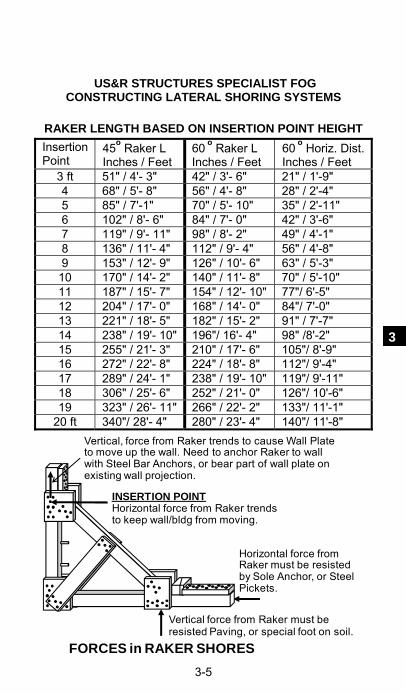
US&R STRUCTURES SPECIALIST FOG CONSTRUCTING LATERAL SHORING SYSTEMS
3-5
3
RAKER LENGTH BASED ON INSERTION POINT HEIGHT
Insertion Point
45o Raker L Inches / Feet
60 o Raker L Inches / Feet
60 o Horiz. Dist.Inches / Feet
3 ft 51" / 4'- 3" 42" / 3'- 6" 21" / 1'-9" 4 68" / 5'- 8" 56" / 4'- 8" 28" / 2'-4" 5 85" / 7'-1" 70" / 5'- 10" 35" / 2'-11" 6 102" / 8'- 6" 84" / 7'- 0" 42" / 3'-6" 7 119" / 9'- 11" 98" / 8'- 2" 49" / 4'-1" 8 136" / 11'- 4" 112" / 9'- 4" 56" / 4'-8" 9 153" / 12'- 9" 126" / 10'- 6" 63" / 5'-3"
10 170" / 14'- 2" 140" / 11'- 8" 70" / 5'-10" 11 187" / 15'- 7" 154" / 12'- 10" 77"/ 6'-5" 12 204" / 17'- 0" 168" / 14'- 0" 84"/ 7'-0" 13 221" / 18'- 5" 182" / 15'- 2" 91" / 7'-7" 14 238" / 19'- 10" 196"/ 16'- 4" 98" /8'-2" 15 255" / 21'- 3" 210" / 17'- 6" 105"/ 8'-9" 16 272" / 22'- 8" 224" / 18'- 8" 112"/ 9'-4" 17 289" / 24'- 1" 238" / 19'- 10" 119"/ 9'-11" 18 306" / 25'- 6" 252" / 21'- 0" 126"/ 10'-6" 19 323" / 26'- 11" 266" / 22'- 2" 133"/ 11'-1"
20 ft 340"/ 28'- 4" 280" / 23'- 4" 140"/ 11'-8"
FORCES in RAKER SHORES
INSERTION POINTHorizontal force from Raker trends to keep wall/bldg from moving.
Vertical, force from Raker trends to cause Wall Plate to move up the wall. Need to anchor Raker to wall with Steel Bar Anchors, or bear part of wall plate on existing wall projection.
Horizontal force from Raker must be resisted by Sole Anchor, or Steel Pickets.
Vertical force from Raker must be resisted Paving, or special foot on soil.

US&R STRUCTURES SPECIALIST FOR CONSTRUCTING LATERAL SHORING SYSTEMS
3-6
RAKER SHORES: Multi-Shore Bracing, Backing, Raker Splice and Anchoring
Splice Horizontal Brace w/ half gusset
Only need middle horizontal brace if raker has mid-brace
This is an example of a four raker system, when the rakers have a mid-brace. X bracing is shown, but V bracing may be used. Normally the X bracing should be installed between the end pair of rakers. X bracing should be no more than 40 feet on center. Place the first diagonal of each set directly against the raker. Place the second diagonal so that it nails to the horizontal braces just adjacent to where the horizontal nails to the rakers. (No nails directly over other nails).
Most all raker installations have multiple numbers of shores that are constructed along a damaged/leaning wall. This section will show information about: Bracing between rakers Backing against wall and Raker Splice Trough Base and Sole Anchors Material List: See each individual system.

US&R STRUCTURES SPECIALIST FOG CONSTRUCTING LATERAL SHORING SYSTEMS
3-7
3
BRACING BETWEEN RAKERS 1. Rakers are normally spaced at 8 feet on center maximum.
However, actual conditions may require closer spacing. 2. Lateral Bracing between rakers is normally built using 2x6
horizontals and X-bracing. 3. Depending on height of insertion point, rakers may have mid-
bracing to reduce to potential of buckling. In this case the lateral bracing will have a horizontal placed near the intersection of mid-brace and raker, and there will be two levels of X-bracing.
4. Horizontal Bracing: 2 x 6 or 2-2x4. Butt splice at center of raker. Preferred if 16ft long. 3 – 16d nails at each horizontal brace to each raker. Cover each splice with Half Gusset, 8-8d.
Horizontal Brace
Raker
5. Middle Horizontal Bracing: (If raker has mid-point brace).
4 x 4 raker: required if length of raker > 11 feet. 6 x 6 raker: required if length of raker > 16 feet. 6. Diagonal Bracing “X” bracing: Use 2 x 6 or 2-2x4 (side by side). Allow no more
than 32 ft (4 bays) between bracing bays. 5-16d each end each brace, and where they cross. ( X-bracing 40 ft max o.c.)
“V” bracing: Same as “X” bracing, but one member of the “X” is placed on the next bay. Allow no more than three un-braced bays between a “V” brace. ( 40 ft max. o.c.)
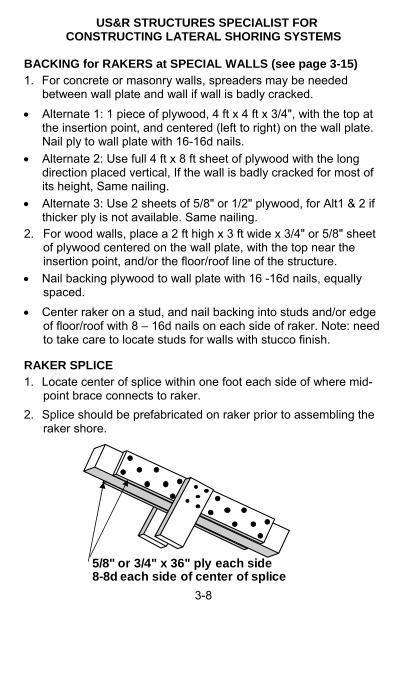
US&R STRUCTURES SPECIALIST FOR CONSTRUCTING LATERAL SHORING SYSTEMS
3-8
BACKING for RAKERS at SPECIAL WALLS (see page 3-15) 1. For concrete or masonry walls, spreaders may be needed
between wall plate and wall if wall is badly cracked. Alternate 1: 1 piece of plywood, 4 ft x 4 ft x 3/4", with the top at
the insertion point, and centered (left to right) on the wall plate. Nail ply to wall plate with 16-16d nails.
Alternate 2: Use full 4 ft x 8 ft sheet of plywood with the long direction placed vertical, If the wall is badly cracked for most of its height, Same nailing.
Alternate 3: Use 2 sheets of 5/8" or 1/2" plywood, for Alt1 & 2 if thicker ply is not available. Same nailing.
2. For wood walls, place a 2 ft high x 3 ft wide x 3/4" or 5/8" sheet of plywood centered on the wall plate, with the top near the insertion point, and/or the floor/roof line of the structure.
Nail backing plywood to wall plate with 16 -16d nails, equally spaced.
Center raker on a stud, and nail backing into studs and/or edge of floor/roof with 8 – 16d nails on each side of raker. Note: need to take care to locate studs for walls with stucco finish.
RAKER SPLICE 1. Locate center of splice within one foot each side of where mid-
point brace connects to raker. 2. Splice should be prefabricated on raker prior to assembling the
raker shore.
5/8" or 3/4" x 36" ply each side8-8d each side of center of splice
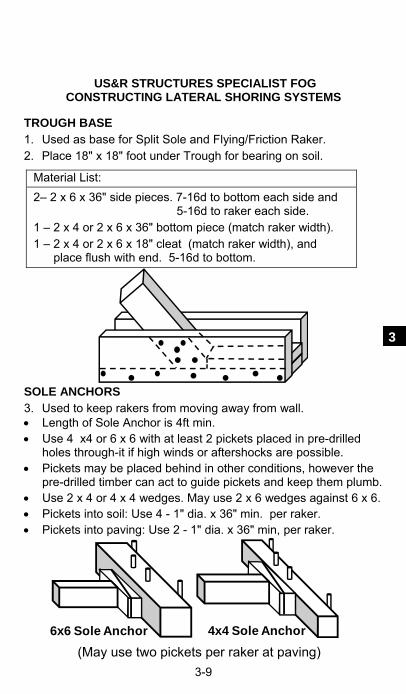
US&R STRUCTURES SPECIALIST FOG CONSTRUCTING LATERAL SHORING SYSTEMS
3-9
3
TROUGH BASE 1. Used as base for Split Sole and Flying/Friction Raker. 2. Place 18" x 18" foot under Trough for bearing on soil.
SOLE ANCHORS 3. Used to keep rakers from moving away from wall. Length of Sole Anchor is 4ft min. Use 4 x4 or 6 x 6 with at least 2 pickets placed in pre-drilled
holes through-it if high winds or aftershocks are possible. Pickets may be placed behind in other conditions, however the
pre-drilled timber can act to guide pickets and keep them plumb. Use 2 x 4 or 4 x 4 wedges. May use 2 x 6 wedges against 6 x 6. Pickets into soil: Use 4 - 1" dia. x 36" min. per raker. Pickets into paving: Use 2 - 1" dia. x 36" min, per raker.
6x6 Sole Anchor 4x4 Sole Anchor (May use two pickets per raker at paving)
Material List: 2– 2 x 6 x 36" side pieces. 7-16d to bottom each side and 5-16d to raker each side. 1 – 2 x 4 or 2 x 6 x 36" bottom piece (match raker width). 1 – 2 x 4 or 2 x 6 x 18" cleat (match raker width), and place flush with end. 5-16d to bottom.

US&R STRUCTURES SPECIALIST FOR CONSTRUCTING LATERAL SHORING SYSTEMS
3-10

US&R STRUCTURES SPECIALIST FOG CONSTRUCTING LATERAL SHORING SYSTEMS
3-11
3
HOW TO CONSTRUCT RAKER SHORES:
Flying Raker – Spot Shore page 3-12
Raker With Backing For Walls 3-15
Solid Sole Raker 3-16
Split Sole Raker 3-20

US&R STRUCTURES SPECIALIST FOR CONSTRUCTING LATERAL SHORING SYSTEMS
3-12
FLYING RAKER (Friction) SHORE (Lateral Class 1)
Design Load is 1,000lb per Raker
Rapidly installed shore that is best used as an initial shore, until a more reliable raker system can be installed. It can be erected next to a wall without removing debris. Material List: 4 x 4 x 6ft Wall Plate One 2 x 4 x 24” Cleat One 4 x 4 Raker 1 Set of 4 x 4 Wedges 2 – 2 x 6 x 48” Braces 2 -1/2" drill-in wall plate anchors Trough Base (see pg 3-9) Sole Anchor with 2 – 1" x 36" Pickets

US&R STRUCTURES SPECIALIST FOG CONSTRUCTING LATERAL SHORING SYSTEMS
3-13
3
HOW TO CONSTRUCT THE FLYING RAKER 1. The area adjacent to where walls need support by rakers should
be considered as very hazardous. Pre-construct each Flying Raker beyond the fall zone, and do not attempt to remove any debris that has fallen next to the damaged wall.
2. Determine where to erect the Flying Raker and the height required to support the wall. Determine height of Insertion Point.
Flying Rakers may be used as single, spot shores, or may be built in pairs with horizontal & X bracing between them.
3. Flying Raker order of construction outline is as follows: In order to pre-fabricate, Cut Raker, Wall Plate and Bottom
Brace to proper length, and perform angle cuts on Raker. Prefabricate the Shore, Trough Base, & Anchor. (page 3-9) Fit the shore into the Trough Base. Place the Anchor for the Trough. Install wedge and/or shims. Attach to wall with 1/2" drill-in anchors (or nails for wood walls). Retighten the wedges. 4. Layout Wall Plate, Raker and Bottom Brace at selected angle,
and toe-nail Raker to Wall Plate. (60 or 45 degree angle OK) 5. Nail-on Top Cleat, then gusset to one side of this joint. 6. Nail one-Bottom Brace to Wall Plate in position to clear debris,
but only tack-nail it to Raker. 7. Turn shore over and nail-on other gusset plus other Bottom
Brace. (nailed to Wall Plate, tack to Raker) 8. Anchor the Trough, then carry the partly assembled Raker into
place. Snug-up the Wedges, and complete the nailing of Bottom Brace to Raker. See page 3-9 for sole anchor.
9. Make whatever connection to wall that is selected, see ADDITIONAL INFORMATION.
10. Retighten the Wedges.

US&R STRUCTURES SPECIALIST FOR CONSTRUCTING LATERAL SHORING SYSTEMS
3-14
ADDITIONAL INFORMATION 1. The areas to be supported by Raker Shores should be
considered extremely dangerous. 2. They may be used as singles spot shores, or may be built in
pairs with horizontal and X bracing added between pairs. 3. To attach wall plate directly to concrete/masonry wall use 1/2"
drill-in anchors as noted below: Place a minimum of two 1/2" x 8 ½" wedge anchors, or 1/2" x 8"
long rebars or smooth bars (4" min embed in wall) through wall plate for 45 deg rakers. Use 3 anchors for 60 deg rakers.
At concrete walls, if 3/4" plywood backing is needed, attached it to wall plate with 16-16d nails, and use at least two 1/2" x 5 ½" wedge anchors, or 1/2" x 8" rebar/smooth bars through backing into concrete wall (4" min embed) each side of Raker.
4. To attach the wall plate directly to a wood framed wall. Use 2 ft high x 3ft wide x 3/4"or 5/8" ply backing nailed with 16-
16d to the wall plate. Center raker on a stud, and use at least 8-16d nails through the backing material into studs and/or edge of floor, each side of Raker.
5. In some cases the drill-ins may be omitted if the top of the Wall Plate can bear against a protrusion in brick/concrete wall. Do not rely on friction.
6. At brick/concrete wall, raker may be built at one edge of a window, with a single or double 2x4 (24" min w/14-16d) pre-nailed to the Wall Plate so it will bear on the bottom of window header (Only if header is not badly cracked).
7. Use a Trough Base and a sole anchor, see page 3-9. 8. A Sole Anchor can be secured to the ground or floor behind the
sole plate to prevent movement of the sole plate. Timber Anchors should be as least 4x4 size lumber, (6x6 is
better). Place 4 – 1" diameter x 36" min. pickets, spaced about 12" on center, directly behind anchor on soil. Two pickets may be used into concrete or paving. See page 3-9
Concrete curbs, walls and other nearby secure structures may also be used.

US&R STRUCTURES SPECIALIST FOG CONSTRUCTING LATERAL SHORING SYSTEMS
3-15
3
RAKER BACKING – USED WHEN SUPPORTING WOOD WALLS See page 3-8 for detail information including nailing. The plywood backing shown may be also used with Split Sole
and Flying Rakers. Plywood is 24" high x 36" wide x 3/4" or 5/8" thick. Nail 16-16d from ply into back of wall plate, and 8-16d each
side of raker into studs and/or edge of floor. The top of the plywood backing should be placed at the
Insertion Point. Center Raker on a stud.
Raker Backing – Used when supporting badly cracked Concrete and Masonry Walls Plywood is 48" high (minimum) x 48" wide x 3/4" thick. Nail 16-16d from ply into back of wall plate. Connect Raker to wall using 2 or more 1/2" x 5 ½" wedge
anchors, or 1/2" x 8" rebars (or smooth steel bars) through the backing material into the concrete wall (4" min. embed. in wall) on each side of the Raker.

US&R STRUCTURES SPECIALIST FOR CONSTRUCTING LATERAL SHORING SYSTEMS
3-16
SOLID SOLE RAKER (Lateral/Class 3)
Foot only at soil bearing
Used in Incidents to stabilize leaning and/or damaged walls. Solid Sole, full triangle, rakers are most desirable, and are built at 45 or 60 deg angle, in groups of 2 or more as Class 3 system with lateral bracing. Material List: (per raker – need two or more)
1 - Wall Plate 2- 1/2" drill-in wall plate anchors for 45 deg. & 3 anchors for 60 deg.
1 - Raker 6 – Full Gussets 2 - Mid-point braces 1 – 4 x 4 Wedge Set
1 – Sole Plate
2- 24" long cleats, 14-16d each for 45 degree rakers Top cleat is 30" long, 20-16d for 60 degree rakers (24" at bottom)
Sole Plate Anchors: 2 - Pickets or 4 (in soil) Foot at soil support: 3- 2 x 6 x 18" or 2 - 3/4" x 18" x 18" square plywood
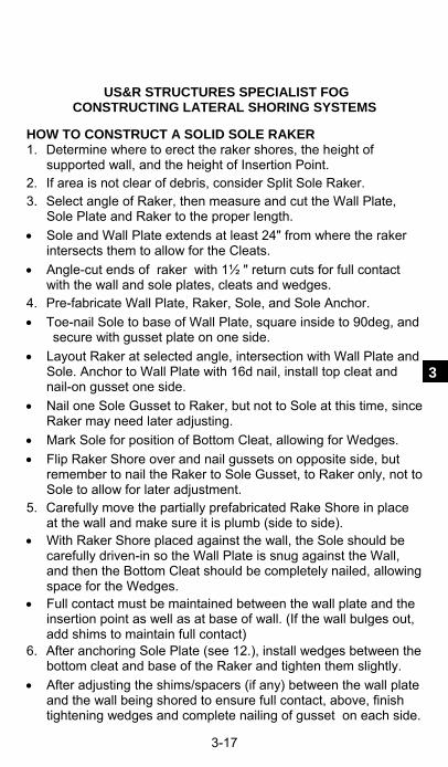
US&R STRUCTURES SPECIALIST FOG CONSTRUCTING LATERAL SHORING SYSTEMS
3-17
3
HOW TO CONSTRUCT A SOLID SOLE RAKER 1. Determine where to erect the raker shores, the height of
supported wall, and the height of Insertion Point. 2. If area is not clear of debris, consider Split Sole Raker. 3. Select angle of Raker, then measure and cut the Wall Plate,
Sole Plate and Raker to the proper length. Sole and Wall Plate extends at least 24" from where the raker
intersects them to allow for the Cleats. Angle-cut ends of raker with 1½ " return cuts for full contact
with the wall and sole plates, cleats and wedges. 4. Pre-fabricate Wall Plate, Raker, Sole, and Sole Anchor. Toe-nail Sole to base of Wall Plate, square inside to 90deg, and
secure with gusset plate on one side. Layout Raker at selected angle, intersection with Wall Plate and
Sole. Anchor to Wall Plate with 16d nail, install top cleat and nail-on gusset one side.
Nail one Sole Gusset to Raker, but not to Sole at this time, since Raker may need later adjusting.
Mark Sole for position of Bottom Cleat, allowing for Wedges. Flip Raker Shore over and nail gussets on opposite side, but
remember to nail the Raker to Sole Gusset, to Raker only, not to Sole to allow for later adjustment.
5. Carefully move the partially prefabricated Rake Shore in place at the wall and make sure it is plumb (side to side).
With Raker Shore placed against the wall, the Sole should be carefully driven-in so the Wall Plate is snug against the Wall, and then the Bottom Cleat should be completely nailed, allowing space for the Wedges.
Full contact must be maintained between the wall plate and the insertion point as well as at base of wall. (If the wall bulges out, add shims to maintain full contact)
6. After anchoring Sole Plate (see 12.), install wedges between the bottom cleat and base of the Raker and tighten them slightly.
After adjusting the shims/spacers (if any) between the wall plate and the wall being shored to ensure full contact, above, finish tightening wedges and complete nailing of gusset on each side.

US&R STRUCTURES SPECIALIST FOR CONSTRUCTING LATERAL SHORING SYSTEMS
3-18
HOW TO CONSTRUCT A SOLID SOLE RAKER (contin.) 7. With Raker shore erected, prevent the Raker shore from sliding
up the wall, using a minimum of 2- 1/2" drill-in anchors with 4" min. embed in wall or other methods. See ADDITIONAL INFO.
8. Attach Mid Point Braces (required if 4x4 Raker is longer than 11 feet and/or 6x6 Raker is longer than 17 feet).
9. Attach Horizontal Braces. Connect Raker shores together near the top and bottom of the
Raker with at least 2x6 size material, or two 2x4s. For Insertion Point greater than 8 feet*, an additional Horizontal
Brace shall be placed at mid-length of the Raker, right where the Mid-Point Braces intersect. *(4x4 longer than 11 ft and 6x6 longer than 17ft).
Horizontal braces may be butt-spliced at center of any raker. Use 3-16d ea end plus half-gusset with 4-8d each side splice.
10. All raker shore systems must be connected with either X or V bracing placed between the horizontal braces, see page 3-6. Use 2x6 or 2-2x4 for each brace.
11. Attach the first brace to the rakers near the top and bottom between the upper and lower horizontal braces. (between the lower and mid-horizontal, and mid and upper horizontal when mid-braces are required.
Attach the second brace to the upper, mid, and lower horizontal braces near the Rakers. (but not on top of the nailing of horizontals to rakers).
12. Methods to Anchor the Sole Plate, in order to prevent the assembled shore from sliding away from the wall.
Preferred Method: Use Sole Anchor as shown on page 3-9 and as noted in ADDITIONAL INFORMATION on next page. This is preferred, since installation can be installed with less risk, at greater distance from wall.
Alternative Method: One may attach the sole plate directly to concrete, asphalt or soil by drilling a minimum of two 1" holes through the sole plate, concrete, or asphalt and drive 1" x 36" steel pickets or rebar directly into the ground below. Need at least 4 – 1"x 36" pickets per raker when no concrete or asphalt paving is present, and anchoring into ground only.

US&R STRUCTURES SPECIALIST FOG CONSTRUCTING LATERAL SHORING SYSTEMS
3-19
3
ADDITIONAL INFORMATION – Solid Sole Raker 1. Design Load for one Raker.
4x4 Raker = 2,500lb 6x6 Raker = 3,600lb
2. Raker information: 4 x 4 maximum length without mid-brace: 11 feet. 6 x 6 maximum length without mid-brace: 16 feet.
3. To attach wall plate directly to a concrete/masonry wall use 1/2" drill-in anchors as noted below:
Place a minimum of two 1/2" x 8 ½" wedge anchors, or 1/2" x 8" long rebar or smooth bar (4" min embed in wall) through wall plate for 45 deg rakers. Use 3 anchors for 60 deg rakers.
At concrete walls, if 3/4" plywood backing is needed, attached it to wall plate with 16-16d nails, and use at least two 1/2"x 5 ½" wedge anchors, or 1/2" x 8" rebar/smooth bar through backing into concrete wall (4" min embed) each side of Raker.
4. To attach the wall plate directly to a wood framed wall. Use 2 ft high x 3ft wide (min) x 3/4" or 5/8" ply backing nailed
with 16-16d to the wall plate. Center raker on a stud, and use at least 8-16d nails through the backing material into studs and/or edge of floor, each side of Raker.
5. Place an 18" x 18" Foot under the sole at intersection of raker, when bearing on soil.
Use 3 – 2 x 6 x 18" or 2 – layers of 3/4" x 18" x 18" plywood.
6. A Sole Anchor can be secured to the ground or floor behind the sole plate to prevent sole plate from backing away from the wall.
Timber Anchors should be as least 4x4 size lumber, (6x6 is better). Place 4 – 1" diameter x 36" pickets per raker, spaced about 12" o.c. into Soil, and as noted on page 3-9. Two pickets may be used into concrete or paving.
Specially made steel anchor brackets may be used with a minimum of 2- 1/2" x 5 ½" wedge anchors into concrete.
Concrete curbs, walls and other nearby secure structures may also be used.
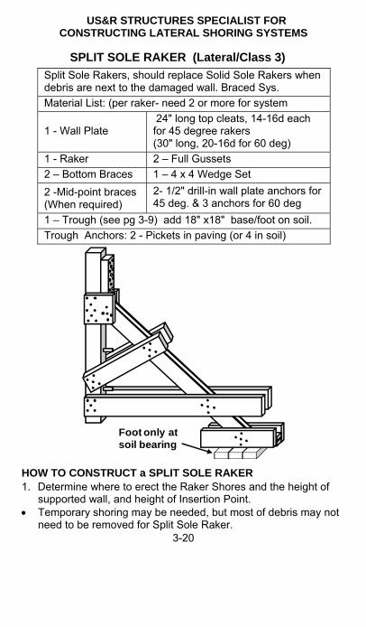
US&R STRUCTURES SPECIALIST FOR CONSTRUCTING LATERAL SHORING SYSTEMS
3-20
SPLIT SOLE RAKER (Lateral/Class 3)
Foot only at soil bearing
HOW TO CONSTRUCT a SPLIT SOLE RAKER 1. Determine where to erect the Raker Shores and the height of
supported wall, and height of Insertion Point. Temporary shoring may be needed, but most of debris may not
need to be removed for Split Sole Raker.
Split Sole Rakers, should replace Solid Sole Rakers when debris are next to the damaged wall. Braced Sys. Material List: (per raker- need 2 or more for system
1 - Wall Plate 24" long top cleats, 14-16d each for 45 degree rakers (30" long, 20-16d for 60 deg)
1 - Raker 2 – Full Gussets 2 – Bottom Braces 1 – 4 x 4 Wedge Set 2 -Mid-point braces (When required)
2- 1/2" drill-in wall plate anchors for 45 deg. & 3 anchors for 60 deg
1 – Trough (see pg 3-9) add 18" x18" base/foot on soil. Trough Anchors: 2 - Pickets in paving (or 4 in soil)

US&R STRUCTURES SPECIALIST FOG CONSTRUCTING LATERAL SHORING SYSTEMS
3-21
3
2. Select angle of Raker, then measure and cut the Wall Plate, Raker, and Bottom Brace to the proper length.
If there is rubble next to wall, wall plate will not extend to ground, and Bottom Brace will be attached at bottom of Wall Plate, and slope to within 6” of Trough Base.
Raker angle may be 45 or 60 deg into Trough Base. Angle-cut both ends of Raker with 1½ " return cuts for full
contact with wall plate, top cleat, and Trough Cleat. 3. Pre-fabricate and cut, Raker, Wall Plate, Bottom Brace, and
Sole Anchor to proper length, and perform raker angle cuts. Layout Wall Plate, Raker and Bottom Brace at selected angle,
and toe-nail Raker to Wall Plate. Nail-on Top Cleat, then gusset to one side of this joint. Nail one-Bottom Brace to Wall Plate, 6” from bottom, or in
position to clear debris, but only tack-nail it to Raker. Turn shore over and nail-on other gusset plus other Bottom
Brace to Wall Plate. Tack-nail Bottom Braces to Raker, so it can be moved to wall. Assemble the Trough, as well as the 18” x 18” foot ( if bearing
on soil), and place in approximate position. 4. Move the partially prefabricated Split Sole Raker Shore in place
at the wall and make sure it is plumb (side to side). After securing the Sole Anchor, adjust the Trough, and drive
wedges slightly against it. Maintain full contact between the wall plate at the insertion point
and at base of wall plate and the wall. For bulging walls, add tight shims/spacers, then finish tightening
wedges & finish nailing of Bottom Braces. Anchor shore to concrete or masonry walls, by placing 2- 1/2"
drill-in anchors for 45 deg. & 3- 1/2" anchors for 60 deg through the wall plate into wall, per ADDITIONAL INFO. 3. For wood walls, center raker on stud and see ADDITIONAL INFO. 4.
Place the Mid-Brace, if required by length of Raker, and erect the Horizontal and X-bracing, per Solid Sole.
Secure the Sole Anchor as shown on page 3-9, and as noted in ADDITIONAL INFORMATION 6 on next page.

US&R STRUCTURES SPECIALIST FOR CONSTRUCTING LATERAL SHORING SYSTEMS
3-22
ADDITIONAL INFORMATION – Split Sole Raker 1. Design Load for one Raker:
4x4 Raker = 2,500lb 6x6 Raker = 3,600lb
2. Raker: 4 x 4 max length w/o mid-brace: 11 feet 6 x 6 max length w/o mid-brace: 16 feet
3. To attach wall plate directly to a concrete/masonry wall use 1/2" drill-in anchors as noted below:
Place a minimum of two 1/2" x 8 ½" wedge anchors, or 1/2" x 8" long rebar or smooth bar (4" min embed in wall) through wall plate for 45 deg rakers. Use 3 anchors for 60 deg rakers.
At concrete walls, if 3/4" plywood backing is needed, attached it to wall plate with 16-16d nails, and use at least two 1/2" x 5 ½" wedge anchor, or 1/2" x 8" rebar/smooth bar through backing into concrete wall (4" min embed) each side of raker.
4. To attach the wall plate directly to a wood framed wall. Use 2 ft high x 4ft wide x 3/4"or 5/8" ply backing nailed with 16-
16d to the wall plate. Center raker on a stud, and use at least 8-16d nails through the backing material into studs and/or edge of floor, each side of Raker.
5. Use the Trough Base with a Sole Anchor. Place a 18" x 18" Foot under Trough Base, when bearing on
soil. Use 3 – 2 x 6 x 18" or 2 - layers of 3/4" x 18" x 18" plywood.
6. A Sole Anchor should be secured to the ground or floor behind the sole plate to prevent the sole plate from backing away from the wall.
Timber Anchors should be as least 4x4 size lumber, (6x6 is better). Place 4 – 1" diameter x 36" pickets per raker, spaced about 12" o.c. into Soil, and as noted on page 3-9. Two pickets may be used into concrete or paving.
Specially made steel anchor brackets may be used with a minimum of two - 1/2" drill-in anchors to concrete.
Concrete curbs, walls and other nearby secure structures may also be used.

US&R STRUCTURES SPECIALIST FOG CONSTRUCTING LATERAL SHORING SYSTEMS
3-23
3
HOW TO CONSTRUCT:
Horizontal Shores page 3-24 Tiebacks 3-27 Raker Shores Using Pneumatic Struts 3-29
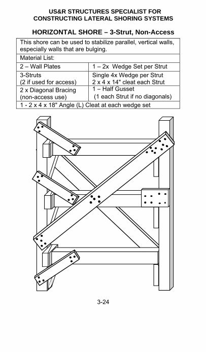
US&R STRUCTURES SPECIALIST FOR CONSTRUCTING LATERAL SHORING SYSTEMS
3-24
HORIZONTAL SHORE – 3-Strut, Non-Access
This shore can be used to stabilize parallel, vertical walls, especially walls that are bulging. Material List: 2 – Wall Plates 1 – 2x Wedge Set per Strut 3-Struts (2 if used for access)
Single 4x Wedge per Strut 2 x 4 x 14" cleat each Strut
2 x Diagonal Bracing (non-access use)
1 – Half Gusset (1 each Strut if no diagonals)
1 - 2 x 4 x 18" Angle (L) Cleat at each wedge set

US&R STRUCTURES SPECIALIST FOG CONSTRUCTING LATERAL SHORING SYSTEMS
3-25
3
HOW TO CONSTRUCT HORIZONTAL SHORE 1. Determine where to erect the horizontal shore. After initial temporary shoring has been installed as needed,
clear the area of debris. A clearance of three to four feet wide is usually adequate. 2. Measure and cut the wall plates & struts to the proper length. Measure between the wall plates where the struts are to be
installed, deducting the width of the wedges. 3. Place both wall plates next to each other and attach cleats and
single 4x wedges to the wall plates just below where the struts will be installed.
If 4x wedge is not available, use 2x wedge on top of a 2x cleat, And nail with 5-16d.
4. Place the wall plates in the area that is to be shored, square and in line with each other and as plumb as possible by shimming any void spaces behind the wall plates.
5. Install the struts between the wall plates. Keep the struts in line and plumb with the wall plates.
6. Install a set of wedges horizontally between the Wall Plate and each Strut, then tap them together simultaneously until the struts are tight.
Toenail the wedges from top into wall plate. May need to use duplex nails for future adjustment.
Add 2 x 4 x 18" cleat from wall plate to strut (on top if possible) to secure wedges & strut. 3-16d each end.
7. At non-wedge end of strut, place half gusset one side. 8. If possible, attach the wall plates to the walls. (as for rakers) 9. Attach the diagonal braces to each side of the horizontal shore
when not used for access or egress. The diagonal braces should be long enough to span entire
length and be attached to both wall plates and each strut. When used, diagonal braces should be installed in a "X" pattern
on opposite sides of struts. 5-16d each end.

US&R STRUCTURES SPECIALIST FOR CONSTRUCTING LATERAL SHORING SYSTEMS
3-26
ADDITIONAL INFORMATION – Horizontal Shore 1. Maximum shore width for 4 x 4 struts: 10 feet. 2. Maximum shore width for 6 x 6 struts: 16 feet. 3. Wall Plates: 4 x 4 or 6 x 6. Spacing for 4 x 4 struts: Maximum 4 feet on center. Spacing for 6 x 6 struts: Maximum 5 feet on center. 4. Miscellaneous: X – bracing is 2 x 6 with 5-16d each end. Place one half of 4 x wedge set under end of strut where
wedges are installed, 5-16d nails. Place 2 x 4 x 18" Angle Cleat to confine wedges, 3-16d each
end. Place 2x, 14" long cleat under opposite end of strut from
wedges. 5-16d nails. Add half gusset on side.
HORIZONTAL SHORE – 2-Strut, Access Type

US&R STRUCTURES SPECIALIST FOG CONSTRUCTING LATERAL SHORING SYSTEMS
3-27
3
WALL TIEBACKS Tiebacks may be used to stabilize hazardous walls that are above the height that can be braced by Raker Shores. Tiebacks are constructed using the following: Strong-backs that extent from at least one floor to the one
above or below. This allows the force placed in the strong-back by the tiebacks to be resisted by the floors of the structure.
Strong-backs may be made from 4x4, 4x6, or double 2x8 or 2x10, depending on floor height. (depending on need)
Tiebacks may be made from very strong rope or wire rope cable. ( 1/4" to 1/2" diameter wire rope cable)
Cable tiebacks can be anchored to the tiebacks using a double basket or choker hitch. (Dbl basket is twice as strong as choker)
Loops may be made in cable using Wire Rope Clips to facilitate the connections.
Cables may be anchored to concrete structure using swivel hoist rings and drilled-in anchors .

US&R STRUCTURES SPECIALIST FOR CONSTRUCTING LATERAL SHORING SYSTEMS
3-28
RAKER SHORE ALTERNATIVES
Note: Make sure that proper pins (by manufacturer) are installed and locked per manufacturer’s recommendations.
US&R STRUCTURES SPECIALIST FOG CONSTRUCTING LATERAL SHORING SYSTEMS
3-29
3
RAKER & HORIZ. SHORES w/ PNEUMATIC STRUTS Pneumatic Strut Manufacturers have developed special configurations that may be used to construct Raker and Horizontal Shores. See following pages for configurations.
Individual Rakers can be configured from two struts plus a special wall plate rail, and special connections.
Manufactured base plates can be connected into paving with 1" x 36" steel pickets driven through existing base plate holes.
When system is constructed on soil, a special angle must be added to the base plate in order to bear on a standard Sole Anchor. (see page 3-9).
A pair of Strut Rakers can be configured as a braced system, using wood X bracing that is connected to special clamp-on brackets that have wood nailers.
When the Raker Strut is longer than 11 feet a mid-brace must be used, and the cross bracing must be a Double X. Note that the mid-brace must be a special strut that is able to resist both tension and compression.
One manufacturer has developed a strut bracing system where the braces can resist both tension and compression forces.
The Raker Rails must be connected to concrete/masonry walls using a minimum of two-1/2" x 5 ½" wedge anchors, or 1/2" x 8" rebar/smooth steel bars with 4" min. embedment in wall. (Two bars for 45 deg., and three bars for 60 deg. rakers).
When supporting wood walls the Raker Rail must be carefully centered on a stud, and two 1/2" x 5" lag screws placed through the pre-drilled holes in the rail. 3/8" lead holes should be drilled at least 4" into the stud.
Low pressure air (50psi max) may be used to extend the struts, but care must be taken to not impact the structure.
Use hand tightening to snug-up all joints. See Section 7 for the tabled that give the Design Strength for
Strut Raker Systems. Note that the connections that anchor the systems to wall and to ground may limit the strength. Consult a qualified Structures Specialist.

US&R STRUCTURES SPECIALIST FOR CONSTRUCTING LATERAL SHORING SYSTEMS
3-30
STRUT RAKER This method uses Wood X Bracing, and length of Raker Strut is 11 feet or less.
Photo of raker using strut bracing – no wood needed

US&R STRUCTURES SPECIALIST FOG CONSTRUCTING LATERAL SHORING SYSTEMS
3-31
3
FULL TRIANGLE STRUT RAKER In this case the Raker Strut is longer than 11 feet, so a mid-
brace must be used as well as Double X-bracing.

US&R STRUCTURES SPECIALIST FOR CONSTRUCTING LATERAL SHORING SYSTEMS
3-32
FULL TRIANGLE STRUT RAKER – ALL STRUTS Photo of Raker Strut that is longer than 11 feet, and a Strut mid-brace is used as well as double X-bracing using Struts.
Note that the mid-brace, horizontal braces and diagonal braces must be special struts that can be adjusted for length, but remain rigid so that they can resist both tension and compression forces.

US&R STRUCTURES SPECIALIST FOG CONSTRUCTING LATERAL SHORING SYSTEMS
3-33
3
FLYING STRUT RAKER
This raker may be used as an initial, spot raker when there is a significant amount of debris at the base of the wall.

US&R STRUCTURES SPECIALIST FOR CONSTRUCTING LATERAL SHORING SYSTEMS
3-34
HORIZONTAL SHORE USING STRUTS This shore would only be used if 4x4 wood struts were not available. As an alternative, if no wood was available, one could use the struts with a Raker Rail against each wall.

US&R STRUCTURES SPECIALIST FOG REPAIRS, FAQ, and GLOSSARY
4-1
4
INTRODUCTION to SECTION 4
This section contains Repair Techniques for Damaged Structures and Frequently Asked Questions and their Answers for FEMA US&R Emergency Shoring, plus a Glossary of Terms, regarding Building Construction and Engineering.
The Repair Techniques are arranged as follows: Page Non-Contact Fiber Wrap 4-4 Epoxy Concrete Repair 4-6 Steel Jacket Column Repair 4-8 Steel Jacket Joint Repair 4-10 Column Stability Repair 4-12 Spray Applied Concrete Repair 4-14 Steel Straps Used To Confine Concrete 4-16 Protected Entry 4-18 Protective Barriers 4-19
The FAQ are arranged as follows: Page Headers 4-20 Posts 4-21 Laced Posts 4-22 Cribbing & Window Shores 4-23 Nails 4-24 Raker Shores 4-26 Diagonal Bracing 4-28 Lumber Grade Adjustments 4-29 Shoring Construction Sequence 4-31 The Glossary of Terms is arranged alphabetically, starting on Page 4-33.

US&R STRUCTURES SPECIALIST FOG REPAIRS, FAQ, and GLOSSARY
4-2
Repair Techniques
Introduction
The strengthening and repair of structural members, components, joints and systems during disaster operations requires innovative design solutions, coordination with contractors and consideration of time and risk. There are no textbook solutions or systems that can be deployed that do not require forethought and engineering expertise. Following are examples and ideas that can be, or have been, used in past disasters to stabilize, repair or strengthen structural buildings and their components during search and rescue operations. They are presented so that the user has a toolbox of alternatives to consider when faced with similar challenges.

US&R STRUCTURES SPECIALIST FOG REPAIRS, FAQ, and GLOSSARY
4-3
4
This page is blank

US&R STRUCTURES SPECIALIST FOG REPAIRS, FAQ, and GLOSSARY
4-4
NON-CONTACT FIBER WRAPS Repair/Retrofit Method: Grout Filled Fiber Plastic Shell Grout Filled FRP Shell: used as a high strength, grout filled form around damaged members. Used for: column confinement; column reinforcing; member stabilization; & component strengthening. Manufacturers: Quake Wrap Fyfe Co. LLC www.pilemedic.com www.fyfeco.com (520)791-7000 (858)642.0694
Applications This grout filled, custom formed FRP Wrap can be applied to damaged steel, concrete or wood members, spalled concrete regions to maintain residual strength or increase strength. Considerations/Limitations Competent Professional Engineer is required for use. Manufacturer input is essential for application and use. FRP cylindrical shell can be fabricated, in-place, to any reasonable size. Wrap is available in 4ft wide rolls. Must have access to all sides of damaged structure. Application Procedure Determine the required diameter and height of the shell. Cut a strip of the wrap material to be the desired height, and about 7 times the desired diameter (allows for a double wrap plus 8”(150 mm) overlap. Use a trowel to apply the special 2-part, paste, epoxy to the outer 60% length of the wrap, prior to installation. (note that a similar system using water activated epoxy bands is under development) Form the wrap into a cylindrical shell around the damaged structure as a double wrap plus about 8”. Temporarily hold the cylinder's shape using nylon ratchet straps in at least two locations within its height. The cylinder may touch the damaged structure at the corners, but it is better if there is at least 1/2” clearance. Mix and place high-strength, non-shrink cementations grout. Pressure of the grout will tighten the wrap layers. Depending on grout, cure time could be 4hrs or more.

US&R STRUCTURES SPECIALIST FOG REPAIRS, FAQ, and GLOSSARY
4-5
4
Installation Sequence: 1. Trowel on 2-part epoxy. 2. Initially place FRP cylindrical shell. 3. Adjust the shell so the 2 layers are in contact. 4. Place ratchet straps to temporarily hold the shell's shape. 5. Mix and pour the non-shrink grout, and use small vibrator or rod
to consolidate.

US&R STRUCTURES SPECIALIST FOG REPAIRS, FAQ, and GLOSSARY
4-6
EPOXY CONCRETE REPAIRS
Repair/Retrofit Method: Epoxy Injected Aggregate Pre-placed aggregate is injected with low-viscosity in order to strengthen badly damaged, oddly shaped structural joints. Manufacturers: Fyfe Co. LLC www.fyfeco.com 858.642.0694 Applications Create a form (using various materials) around the damaged concrete regions to encompass the repair area. Clean, pea-gravel aggregate is carefully placed in the form, and then injected (starting at the bottom) with low-viscosity epoxy. This method is most applicable for repairing badly damaged joints that are difficult to surround using cylindrical shells or jackets. Considerations/Limitations Competent Professional Engineer is required for use. Manufacturer input is essential for application and use. Plaster covered metal lath has been used as a custom fit form. Plywood has also been used as a form. Aggregate must be clean any have uniform size in order to allow the epoxy to flow into the voids. The epoxy should be injected starting at the lowest point of the formed repair, and ports should be placed every 4” (100 mm) above so that epoxy can be seen to slowly rise within the aggregate. As the epoxy reaches each successive port the lower one should be closed, and then epoxy injected into the port at the current level of the epoxy. It is very important to use the proper, low-viscosity epoxy in order to avoid having the curing reaction generate too much heat (exothermic reaction). Consult epoxy manufacturer and knowledgeable, specialty contractor. Cure times for epoxy vary. Consult the Manufacturer.

US&R STRUCTURES SPECIALIST FOG REPAIRS, FAQ, and GLOSSARY
4-7
4
Before After Repair of Badly Damaged Column in Puerto Rico

US&R STRUCTURES SPECIALIST FOG REPAIRS, FAQ, and GLOSSARY
4-8
STEEL JACKET COLUMN REPAIR
Repair/Retrofit Method: Concrete filled Steel Jacket
Jacket a damaged column with full height steel shell and fill with structural concrete for stability and/or strengthening.
Manufacturers: Coordinated engineer, contractor & fabrication shop. Applications Primarily used for damaged columns. Applicable to any type of column (concrete, steel, etc). Considerations/Limitations Competent Professional Engineer is required for use. Steel encasement is prefabricated in two half rounds and bolted and/or welded together. Bolting is preferred since less time is spent in danger area during erection. Steel encasement is 3/16” to 1/4” (4 to 6 mm) thick. Encasement should clear damaged column by at least 3” (80 mm)
This photo shows a set of half-round steel encasements just prior to erection. Note that the steel encasement is stacked two high in this installation.

US&R STRUCTURES SPECIALIST FOG REPAIRS, FAQ, and GLOSSARY
4-9
4
Damaged columns with completed encasement

US&R STRUCTURES SPECIALIST FOG REPAIRS, FAQ, and GLOSSARY
4-10
STEEL JACKET JOINT REPAIR
Repair/Retrofit Method: Grout Filled Steel Jacket Jacket column joint with steel shell and fill with fast setting, high strength non-shrink grout for stability and/or strengthening. Manufacturers: Coordinated engineer, contractor & fabrication shop. Applications Primarily used for damaged column joints. Applicable to any type of column. Shown below for large concrete column joint retrofit. Steel encasement was prefabricated from four steel angles and four steel plates. It was prefabricated as two halves, then erected and welded at the two unconnected corners. Considerations/Limitations Competent Professional Engineer is required for use. The space between the column and jacket should be kept small in order to minimize the thickness of the grout. The steel used for a square jacket needs to be in the range of 3/8” minimum thickness. For ease of fabrication the corners should be made using steel angles. (L3 x 3 x 5/16” minimum) Temporary forms will usually be needed that are placed on sound concrete below the jacket, in order to support it and keep the grout in place until it hardens. High strength, cementations, non-shrink grout should be used. It is available in bags, can be mixed in the field, and can attain strengths exceeding normal concrete in 12 to 24 hours (depending on outside temperature). The steel jacket may be heavy, with each side weighing 100 lbs (45 kg) or more. Therefore some sort of equipment may be require to lift it into place.
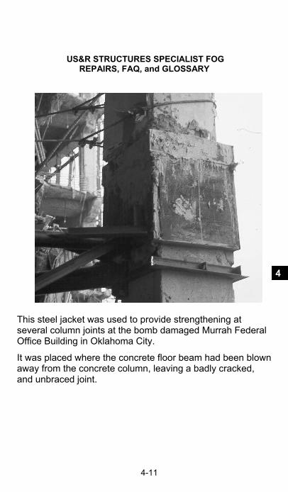
US&R STRUCTURES SPECIALIST FOG REPAIRS, FAQ, and GLOSSARY
4-11
4
This steel jacket was used to provide strengthening at several column joints at the bomb damaged Murrah Federal Office Building in Oklahoma City.
It was placed where the concrete floor beam had been blown away from the concrete column, leaving a badly cracked, and unbraced joint.

US&R STRUCTURES SPECIALIST FOG REPAIRS, FAQ, and GLOSSARY
4-12
COLUMN STABILITY REPAIR
Repair/Retrofit Method: Column Length Bracing Supporting columns and reducing the column length with bracing members. Manufacturers: Coordinated engineer, contractor & fabrication shop. Applications Primarily used for damaged columns that have become unsupported at floor levels. Applicable to any type of column. Additional bracing members attached to column in critical buckling directions. Steel pipes or tubes are commonly used for bracing members. Considerations/Limitations Competent Professional Engineer is required for use. Bracing should be provided in the north-south as well as east-west direction at each level where the floors have been dislodged, if possible. Braces need to be of sufficient size to resist both compression and tension forces. Braces need to be positively connected at each end and the anchoring structure must be adequately strong and rigid. The minimum design force for the braces should be at least 2 percent of the total force in the damaged column. If the column is mis-aligned, the design force should be 5 percent minimum.

US&R STRUCTURES SPECIALIST FOG REPAIRS, FAQ, and GLOSSARY
4-13
4
This cross-section at the Murrah Federal Office Building in Oklahoma City shows how a truss work of pipes was used to laterally brace Columns F22 and F20. The floors on all sides of these columns had collapsed up to the 4th Fl, and they were in danger of collapsing as the debris was being removed to access the buried victims.
This schematic, partial cross-section of the World Trade Center Basement following the 1993 Truck Bombing shows the configuration of steel tube bracing that was used to brace the steel basement columns after the basement parking garage concrete floor slabs had collapsed, leaving the steel columns standing 70 ft tall without lateral support.

US&R STRUCTURES SPECIALIST FOG REPAIRS, FAQ, and GLOSSARY
4-14
SPRAY APPLIED CONCRETE REPAIR
Repair/Retrofit Method: Shotcrete/Gunite, Cementitious Spray-on Concrete/Mortar. Spray on concrete type material that can stabilize or strengthen members, components and systems.
Manufacturers: Local Contractors, especially those with swimming pool experience.
Applications Damaged concrete regions are stabilized or strengthened with sprayed-on concrete type material (Gunite/Shotcrete, Air Blown Concrete). The affected area is encased with a concrete outer shell. Reinforcing steel or mesh may be placed first, in order to provide greater strength.
Considerations/Limitations Competent Professional Engineer is required for use. Application Contractor's input is essential to determine limitations and required logistics. The shotcrete requires at least 5 days to develop half of its strength, and 21 days to develop about 90% strength. The shotcrete should be cured by applying a moisture preserving seal-coat and/or keeping the surface damp. For greater reliability an above grade footing should be poured completely around the base of the wall, prior to applying the shotcrete. See next page for use of shotcrete in New Zealand, March 2011.

US&R STRUCTURES SPECIALIST FOG REPAIRS, FAQ, and GLOSSARY
4-15
4
Wall Before Shotcrete
Wall After Shotcrete
Overall View of Repair Using Shotcrete
Spray Applied M
aterials

US&R STRUCTURES SPECIALIST FOG REPAIRS, FAQ, and GLOSSARY
4-16
STEEL STRAPS USED TO CONFINE CONCRETE Repair/Retrofit Method: Steel Strapping Tape Confinement of damaged concrete members using Heavy Duty Steel Strapping. Manufacturers/Distributers: Globalindustrial.com, Uline.com
Applications Damaged concrete members can be confined by binding the damaged area with many layers/widths of steel strapping.
Considerations/Limitations
Easy to use and apply. Available locally. Confinement of damaged concrete members can be improved easily. Strapping may be applied around wood and/or plywood spreaders to better confine the concrete. Strapping is available in 1/2”, 5/8”, and 3/4” wide rolls (10 to 20 mm) in varying gauges. Proper installation requires tools to tighten, clamp the seal and cut the strap as shown below.

US&R STRUCTURES SPECIALIST FOG REPAIRS, FAQ, and GLOSSARY
4-17
4
Column F-22 at the Murrah Federal Office Building in Oklahoma City, where the Third Floor used to be. Steel strapping was used as a temporary measure prior to installing a grout filled steel jacket.
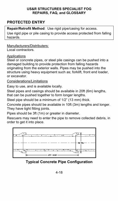
US&R STRUCTURES SPECIALIST FOG REPAIRS, FAQ, and GLOSSARY
4-18
PROTECTED ENTRY
Repair/Retrofit Method: Use rigid pipe/casing for access. Use rigid pipe or pile casing to provide access protected from falling hazards. Manufacturers/Distributers: Local contractors.
Applications Steel or concrete pipes, or steel pile casings can be pushed into a damaged building to provide protection from falling hazards originating from the exterior walls. Pipes may be pushed into the structure using heavy equipment such as; forklift, front end loader, or excavator.
Considerations/Limitations
Easy to use, and is available locally. Steel pipes and casings should be available in 20ft (6m) lengths, that can be pushed together to form longer lengths. Steel pipe should be a minimum of 1/2” (13 mm) thick. Concrete pipes should be available in 10ft (3m) lengths and longer. They have tight fitting joints. Pipes should be 3ft (1m) or greater in diameter. Rescuers may need to enter the pipe to remove collected debris, in order to get it into place.
Typical Concrete Pipe Configuration

US&R STRUCTURES SPECIALIST FOG REPAIRS, FAQ, and GLOSSARY
4-19
4
PROTECTIVE BARRIERS Repair/Retrofit Method: Use Rigid Containers & Boxes as Barriers. Use shipping containers and/or rigid boxes as protective barriers. Manufacturers/Distributers: Shipping companies, Concrete vault suppliers, and waste disposal companies. Azteccontainer.com; Steelshippingcontainer.com; Onsitestorage.com. Applications Use shipping containers, dumpsters, and/or concrete vaults as barriers adjacent to hazardous buildings and vulnerable rock faces.
Considerations/Limitations
Easy to use, and available locally. Shipping containers are available in 20, 40, 45 and 48 foot lengths. Steel debris boxes (dumpsters) may also be used, and are available in 3, 5, 8, 15, 18, 20, 30, and 40 cubic yard sizes. These rigid containers can be ballasted with heavy objects, such as water bladders, sand bags, and steel scrap, in order to add sliding and overturning resistance. Containers may be stacked up to 3-high, but should be connected together using chains or high strength straps. Containers may be placed 2-wide to improve resistance.

US&R STRUCTURES SPECIALIST FOG REPAIRS, FAQ, and GLOSSARY
4-20
FREQUENTLY ASKED QUESTIONS
HEADERS Question H-1 What to do if need 4x6 header and only have 4x4 and 2x4 material? Ans.H-1a Nail 2x4 to top of 4x4 with 16d@3” o.c. This build-up is about 80% as strong as 4x6
Ans.H-1b Stack 2-4x4 and toenail together. This build-up is slightly stronger than 4x6
Ans.H-1c Place 2-2x6 side-by-side with ½” or ¾” plywood in between. Inter-nail with 16d@8″ o.c.
Question H-2 What to do if need 4x8 header and only have 4x4 and 2x4 material?
Ans.H-2 Stack 2-4x4 and place ½” or ¾” plywood each side. Nail 8d@3” o.c. each side to each 4x4. (stop ply short of posts)
Question H-3 How big of a Header is needed? Ans.H-3a To support a damaged wood structure, use a 4x4 header as minimum and add 1” to depth for each additional foot of span larger than 4 ft. Example use 4x6 for 5 ft span and 4x8 for 8 ft spans. For 6x6 posts you may use a 6x6 header for 5ft o.c.
Ans.H-3b To support a damaged concrete structure, header size depends on the condition of the concrete structure.
To support a minimally cracked concrete beam or slab, with 4x4 posts spaced at 4 ft o.c., use a 6x6 header with 6x6 post spaced 5ft o.c. Since the concrete structure is stiffer and stronger than most any wood header, the concrete will span between posts so the header functions mostly as an interconnection of the posts and diagonal bracing.
To support badly cracked concrete slabs and beams, the header should be sized by the Structures Specialist (StS) If StS is not available, then use 4x8 header for 4x4x 8ft long posts (8000lb capacity) spaced up to 4 feet. Use 6x12 for 6x6x12ft long posts for spans up to 4ft. For 5ft spans the capacity would be reduced by 10%, and for 6ft spans the capacity would be reduced by 25%.
US&R STRUCTURES SPECIALIST FOG REPAIRS, FAQ, and GLOSSARY
4-21
4
POSTS
Question P-1 If only 2x4, 2x6, 2x8 and 4x4 are available, how to create a 6x6 or 8x8 post?
Ans. P-1a To construct a 6x6 one may use the following: Build-up 4-2x6 to form a 5½” x 6” net post. Inter-nail with 16d@8”o.c. staggered plus add ½″ carriage bolt 6” from each end and 3ft o.c. As alternate to the bolts add 6”x ¾” x 12” plywood gussets on 6” faces at same spacing
As a less desirable option, add 2x6 to side of 4x4, plus 2x4 +½″ plywood fill to adjacent side. Inter-nail with 16d@8”o.c.
Ans. P-1b To construct an 8x8 one may use the following: Build-up 5-2x8 and inter-nail with 16d@8” o.c., plus add ½” carriage bolt 6” from each end and 3ft o.c. As alternate to the bolts add 6”x ¾” x 12” plywood gussets on 8″ faces at same spacing
or Build-up 4-4x4 to from a 7”x7” net post. Place 12” long x ¾” plywood gussets on all 4 sides at top and bottom, plus 3ft max. o.c. Nail each gusset to each 4x4 with 8d in 5-nail pattern
Question P-2 What to do if post spacing is not exactly as shown in FOG?
Ans. P-2 Most types of shores that we build have posts spaced at between 30” and 4ft o.c. and headers should be sized accordingly (as indicated in Ans. H1 through H3). The total capacity of the posts should always be more than the total load. Remember that the capacity of a 4x4x8ft high post is 8000lb and a 6x6x12ft high post is 20,000lb.
If the post spacing is more than 5ft o.c. the header size should be increased, or the capacity should be decreased. Decrease capacity 10% for a 6” increase in post spacing , and 25% for a 1ft increase in spacing.

US&R STRUCTURES SPECIALIST FOG REPAIRS, FAQ, and GLOSSARY
4-22
LACED POSTS Question LP-1 What is the correct configuration of the diagonals, and does it really matter?
Ans. LP-1 The following standard has been adopted: The two sides of the Laced Post should be made the same (for simplicity) and the diagonals should be in a ″K″ configuration. When one looks through the finished Laced Post from the side, the diagonals should form an ″X″.
After the end horizontals are placed, the end diagonals should also be configured as a ″K″. When one looks through the Laced Post from the end, the diagonals should form an ″X″.
This configuration is the easiest to remember, but any other configuration may be used, as long as one does not have too many diagonals intersecting at same location on a single post.
In previous editions of the USACE StS FOG, it was stated that having the diagonals at one side of the Laced Post configured as a reverse K (and the other 3 as a K) was preferred. However, when this is done, there will be 4 diagonals and 2 horizontal braces intersecting at one location on one 4x4 post. This can cause splitting of the post.
It should be noted that twelve Laced Post Systems, (13ft high) were tested from April 2000 to May 2006 - All failures occurred at more than 3 times the design load. Also significant cupping of wedges was observable when the load reached 2 times the design load, giving ample warning of system failure. Various configurations of diagonals were used. Question LP-2 If the Maximum Height to Width Ratio of Laced Post is 4 to 1, why can you build a system with 4x4 post at 4ft o.c. up to 17ft high ?
Ans. LP-2 The 4 to 1 max. is based on the out to out dimension, and for posts 4ft o.c., the 4x out to out is 17'-2” USE 17 feet (Please note that the maximum height tested is 13 feet).

US&R STRUCTURES SPECIALIST FOG REPAIRS, FAQ, and GLOSSARY
4-23
4
CRIBBING Question CB-1 Maximum height to width ratio is specified as 3 to 1 in the Shoring Training (SCT, Mod 2) and 2 to 1 in Lifting and Moving Training (SCT Mod4), which is correct? Ans.CB-1 Actually, both are correct. For normal shoring where Cribbing is constructed to support a damaged structure the 3 to 1 ratio may be used, assuming that the Crib is being loaded, more or less, uniformly. When Cribbing is being used in a ”Lift a little and Crib a little”
application the 2 to 1 ratio is more appropriate due to the more dynamic nature of the potential loading.
For both cases the height of cribbing should be minimized, since differences in the hardness of adjacent pieces of wood can cause differential deflection that can lead to instability. Therefore it is recommended that cribs using 4x4 lumber be limited to 4ft in height (6x6 limit to 6ft in height). If greater height in needed, these effects can be minimized by using a 3 member x 3 member layout.
WINDOW SHORES Question W-1 Why do we need to provide wedges in both Horizontal and Vertical directions for these shores? Ans.W-1 The need for the wedges in the Vertical direction is easily understood. The wedges that bear on the Sides of the openings at top and bottom are very important is situations where the Openings will tend to Rack or Bulge, such as Earthquakes, and the Window Shore should be strongly ″X″ braced in this case.

US&R STRUCTURES SPECIALIST FOG REPAIRS, FAQ, and GLOSSARY
4-24
NAILS Question N-1 What embedment is required to develop the full value of a nail? Ans.N-1 In general, nails should be embedded a little more than one half their length in the piece into which they are anchored. Example: 16d is 3.5” long and required full embedment is 1.94”. Question N-2 What should we do when nailing a 2x to a 2x, since the embedment is only 1.5”? Ans.N-2 The strength of these nails is 77% since the embedment ratio is 1.5/1.94. Since most 2x to 2x nailing involves lateral bracing connections, this is close enough. Question N-3 Can we use 16d Cooler Nails (.148”x3.25”) instead of 16d common? (.162”.x3.5”) Ans.N-3 Yes, since it is very important to minimize the splitting of wood in nailed joints, and 16d vinyl coated nails cause much less splitting and drive easier. These cooler nails may be used in FEMA shoring without significant reduction in strength. 8d & 16d cooler nails have been used in Rakers as well as
Laced Posts that have been tested during Structures Specialist Training. There was no significant difference in test results, from those tests using common nails.

US&R STRUCTURES SPECIALIST FOG REPAIRS, FAQ, and GLOSSARY
4-25
4
NAILS (continued) Question N-4 What nailing should be used if Doug. Fir or Southern Pine lumber is unavailable? Ans.N-4 As previously discussed, the nail strength value is approximately based on the density of wood, therefore reduce all nail values for the following: For Hem-Fir and Spruce-Pine-Fir reduce strength by 15%
For Eastern Softwoods, Western Cedar & Western Woods
reduce strength by 25%
This means that one should, accordingly, reduce the capacity of shoring, built using these species. However, for Raker Shores, since the strength is effectively based on the Cleat nailing or the Picket/Soil strength, one may add 3-nails to the 17-nail pattern when using species with either 15% or 25% strength reduction species. Question N-5 What nailing should be used to connect rough cut 2x lumber, that is a full 2” thick? Ans.N-5 In order to obtain adequate embedment, one should use 20d box nails instead of 16d. The 20 box nail has about 90% the strength of 16d common and same as the 16d cooler.

US&R STRUCTURES SPECIALIST FOG REPAIRS, FAQ, and GLOSSARY
4-26
RAKER SHORES Question R-1 What is the most appropriate spacing for Raker Shores? Ans.R-1 The spacing should be based on the height, weight and condition of the wall being supported. Solid Sole and Split Sole Rakers are designed to support a 2500lbs horizontal force. A Structure Specialist should be asked to evaluate the situation, and specify the required spacing. In any case Raker Shores should not be spaced more than 8 feet. Question R-2 How far should a Raker be spaced from the corner? Ans. R-2a This depends on the condition of the wall. If the wall corner is badly cracked, it would be appropriate to place the first Raker as near the corner as possible. Also in many cases URM corners may have large diagonal cracks that appear to form a ”V” that tends to allow a large wedge of masonry to fall from the corner. In this case one may need to place one or more Rakers in each direction near the corner. Ans. R-2b When wall corners have little damage, the first Raker may be spaced from 4ft to 8ft from the corner. Question R-3 What is the best configuration of the Flying (or Friction) Raker? Ans.R-3 Flying Raker is the weakest type of Raker, but are useful when debris are found at the base of the damaged wall. When the Bottom Brace is configured as a horizontal, there is a tendency to bend the Raker and Kick it Out at the Ground. Therefore, the Bottom Brace should be sloped down to intersect the Raker as near to the top of the Trough Base as possible.

US&R STRUCTURES SPECIALIST FOG REPAIRS, FAQ, and GLOSSARY
4-27
4
RAKER SHORES (continued) Question R-4 When should one use a 30 degree Raker? Ans. R-4 The 30 degree Raker is the most efficient Raker, since the flatter angle allows the horizontal resistance to be 86% of the Raker Force, and the Vertical lift is only 50% of the Raker Force. However, access, and height of insertion point may not allow the 30 degree configuration to be easily constructed.
Also it takes a longer Raker to reach the same insertion point as for 45 & 60 degree Rakers.
30 degree Rakers should be used when bracing the One-Sided Trench (if possible).
Question R-5 How should one cut the ends of the Raker when construction a 60 degree Raker when the wall plate has been notched out as per instructions? ANS. R-5 The 1” notch is no longer recommended for 60 degree Rakers. Use a 30” cleat with 20-16d nails for a 4x4 Raker System.

US&R STRUCTURES SPECIALIST FOG REPAIRS, FAQ, and GLOSSARY
4-28
DIAGONAL BRACING Question DB-1 Under what conditions does one need to use Diagonals in a ″X″ configuration, and when is a single Diagonal acceptable (as in Laced Posts)? Ans.DB-1 Based on the Maximum Length to Width Ratio of 50 (L/D=50 max.), if a 2x Diagonal Brace is more than 7'-6” long, one must use an ″X″ since it must be assumed that the 2x can only resist a tension force. If the Diagonal is 7'-6” or less in length, the 2x can resist tension or compression, and, therefore a single Diagonal may be used. Based on this information, it should be understood that the
maximum spacing for Laced Posts is 4 ft for 4x4 & 5 ft for 6x6
- If the Laced Post is more than 11 feet high, a configuration of three Diagonals per side is required.
- If the Laced Post is more than 17 feet high, a configuration of four Diagonals per side is required.
Question DB-2 Is it necessary to nail one X-brace to the other at the crossing? Ans. DB-2 Technically, no nailing is required, but it is a good idea, since it could make the bracing system stiffer by allowing each brace to partly restrain the other in the weak (1 1/2”) direction. A minimum of 3 nails should be used.

US&R STRUCTURES SPECIALIST FOG REPAIRS, FAQ, and GLOSSARY
4-29
4
LUMBER GRADE
Question L-1 What adjustments are needed if Douglas Fir or Southern Yellow Pine timber is not available? (Applies to Vertical and Laced Post shores, Cribbing, Sloped Floor and Raker shores)
Ans. L-1 Lumber strength and nail strength values , in general, are based on the density of the wood species. The following reduction in strength values should be used: For Hem-Fir and Spruce-Pine-Fir, reduce strength by 15% For Eastern Softwoods, Western Cedar & Western Woods,
reduce strength by 25% This means that the capacity of the shoring should be reduced proportionally or the post spacing should be reduced proportionally Example: for 15% reduction in post spacing, 4 ft would become 3′ - 6”. For 25% reduction, 4 ft would become 3 ft.
Question L-2 What is strength reduction if pressure treated lumber is used? (may be called CCA, Wolmanized, NatureWood, Natural Select )
Ans. L-2a Most all commercially treated sawn lumber that has been treated with a ”Preservative” to reduce its susceptibility to insects and decay, has been embedded with some sort of Copper-based preservative or with Creosote. Chromated Copper Arsenate (CCA) has been the most common for sawn lumber, but due to environmental concerns, other Copper based preservatives are being introduced.
Ans. L-2b No ”Significant” reduction in wood strength occurs due to treatment using Copper based compounds. However, most pressure treated sawn lumber will be sold in a ”Dry” condition which makes it more susceptible to splitting caused by nailing. Also some treated wood may be split and or warped. One should use a ”Common Sense” approach and avoid badly split or warped wood, especially for critical parts of shoring like Raker Cleats and the Diagonals in Laced Post Systems.

US&R STRUCTURES SPECIALIST FOG REPAIRS, FAQ, and GLOSSARY
4-30
MISCELLANEOUS QUESTIONS
Question M-1 Should we shore Steel Bar Joist from the bottom (Bottom Chord), or do we need to place the shoring system up under the top (Top Chord)?
ANS. M-1 One should not place a shoring system directly under the bottom of bar joist or any thin, tall truss (like timber trusses made from 2x). However, there may be cases where you don't have any other reasonable choice. In that case one needs to do the following:
Check with your Structures Specialist (StS). Place shores directly under the intersection of the web
members in more than one location for the same group of trusses. That is, spread out the load as much as possible so as not to overload any one of the truss diagonals.
If some perpendicular to the truss, bracing is present, place the shores as near that location as practical, keeping the other considerations, listed above.
It is best to have a StS give you advice on any particular situation.
Question M-2 Should we secure the sole of a sloped floor shore?
ANS. M-2 Absolutely, yes one should secure the sole. Most sloped floors would be somewhat unpredictable, and securing the sole could be very beneficial.
Question M-3 Should we place the wedges at the top or at the bottom of a Prefabricated Door or Window Shore, when there is the possibility that the bottom will become submerged?
ANS. M-3 There is no structural problem in placing the wedges at the bottom in this case, but how would one check and re-tighten, if under water. In this (or any) case, there is no problem in having the wedges at the top. In fact in all cases of Prefabricated Window/Door one could have wedges and/or shims at the top and/or bottom, especially if the header is sloped.

US&R STRUCTURES SPECIALIST FOG REPAIRS, FAQ, and GLOSSARY
4-31
4
PREFERRED SHORE CONSTRUCTION SEQUENCE
Shoring during long-term incidents should be constructed with as much prefabrication as practical, and in a sequence that provides an increasingly safer rescue environment.
However, there will be many incidents that have a relatively short duration, and may only require spot shores and/or 2 and 3 post vertical shores. In these and other cases it also may not be practical to prefabricate the shoring.
The ”Preferred Sequence” that is suggested here, should be followed, only if it is practical, as in a damaged concrete structure that requires a prolonged shoring operation.
Vertical Shoring should begin with the installation of spot shores, such as a Tee Shore, Double Tee Shore, Pneumatic Struts or a single post.
- These may be called Class 1 Shores (one dimensional).
- Class 1 shores are intended to quickly reduce risk, for a short period of time.
- The Double Tee is actually more like a Class 2 Shore.
If the Rescue Scenario is prolonged, then one should further reduce risk by installing 2-Post Vertical Shores (or single Sloped Floor Shores).
- The 2-Post Vertical is just half of a Laced Post, and can be partly prefabricated, and quickly carried into place.
- These may be Class 2 Shores (two dimensional).
- Vertical Shores with 3 or more posts are difficult to prefabricate and to develop into a full 3-Dimensional Systems. However they may be very useful in providing continuous support under damaged beams or a series of broken wood, floor joist.

US&R STRUCTURES SPECIALIST FOG REPAIRS, FAQ, and GLOSSARY
4-32
PREFERRED SHORE CONSTRUCTION SEQUENCE (continued)
The next step in the Shoring Sequence would be to convert the 2-Post Shores into Laced Post Shores (or complete the Sloped Floor Shores as Braced Pairs). - These are well braced 3-Dimensional Systems, and may
be called Class 3 Shores. - Class 3 Shores are the most stable systems that we can
build, and one may make them more stable by anchoring the Sole Plates to the concrete slab.
Cribbing is a 3-dimensional system, but most cribs rely on, only, friction for lateral bracing.
If more positive lateral bracing is desired, cribs may be sheathed with plywood on all 4 sides, or metal clips may be installed at the corners.
The base members could also be restrained from sliding on the concrete slab by using anchor bolts or assemblies similar to Rake Sole Anchors.
Raker Shores should be installed using a similar progression.
First one Raker would be built and moved into place.
Then another could be paired with the first, with X bracing between them.
This could be followed by an entire series of Rakers that extend the full length of the damaged wall.
All Rakers should be prefabricated as much as possible.
A Pneumatic Strut, Raker System or Systems may be used as the initial, temporary Raker System.
Preplan to make sure that the temporary Raker System is smaller than the Final Systems, so it may be built over, and removed after the final Raker System is completed.
Pneumatic Strut Systems are available that allow a pair of Rakers to be cross braced, also they can have a mid-point brace installed to improve the stability of the system.

US&R STRUCTURES SPECIALIST FOG REPAIRS, FAQ, and GLOSSARY
4-33
4
GLOSSARY OF TERMS Arch- A curved structure used as a support over an open space. It produces an outward thrust as well as downward forces at its supported ends.
Axial load- A tension or compression load which passes through the center of a structural member (like a column, beam, truss member, diagonal brace or hanger rod).
Bay- The space between beams/trusses or between rows of columns considered in transverse planes.
Beam- A horizontal structural member, subject to compression, tension, and shear, usually found in any one of three different configurations: cantilever, continuous, and simple.
Bearing Wall- An interior or exterior wall that supports a load in addition to its own weight.
Brick Veneer- A single thickness of brick wall facing placed over frame construction or structural masonry.
Buttress- A wall reinforcement or brace built on the outside of a structure, sometimes called a ”wall column.” When separated from the wall and connected by an arch at the top, it is called a flying buttress.
Cantilever Beam- A beam that has two or more supports but extends beyond one end support and ends in clear space (similar to a diving board).
Cavity Wall- A wall of two parallels wythes (vertical wall of bricks, one masonry unit thick) separated by an air space. Wythes are connected by metal ties.
Chair- A device of bent wire used to hold reinforcing bars in position.
Check- A lengthwise separation of wood fibers, usually extending across the annular rings. Check commonly result from stresses that develop in wood during the seasoning process.
Choker Hitch- A sling where one end passes through the eye of the opposite end (or through the inside of the opposite loop of an endless sling) and is pulled tight around the object that is to be lifted (like a Larks Foot).
US&R STRUCTURES SPECIALIST FOG REPAIRS, FAQ, and GLOSSARY
4-34
Chord- Main members of trusses as distinguished from diagonals.
Collapse
Definition- The failure of any portion of a structure.
Cantilever Collapse- When many sections of floor collapse, and one or more sections extend out from the remainder, like a diving board.
Curtain Fall Wall Collapse- One of the three types of masonry wall collapse, it occurs when an exterior masonry wall drops like a falling curtain cut loose at the top.
Lean-over Collapse- Typical wood frame building collapse when the structure starts to Rack (form a parallelogram), and eventually collapses so that the structure is offset by the story height of however many stories collapse .
Lean-to-Floor Collapse- A floor collapse in which one end of the floor remains partially supported by the bearing wall and the other end of the floor collapses on to the floor below.
Ninety Degree Wall Collapse- The wall falls straight out as a monolithic piece at a 90 degree angle, similar to a falling tree.
Pancake Floor Collapse- Collapse of one or more floors upon the floors or ground below into a pancake configuration.
Tent Floor Collapse- Floor collapse into the shape of a tent.
V-shape Floor Collapse- The collapse of a floor at the interior of a building, so that one end of two adjoining sections of floor are no longer supported (by a beam or wall).
Column- A vertical structural member subject to compressive forces. Compression- A force which tends to push the mass of a material together. Concentrated Load- A load applied at one point or within a limited area of a structure.

US&R STRUCTURES SPECIALIST FOG REPAIRS, FAQ, and GLOSSARY
4-35
4
Concrete –
Definition- A material used in construction that is extremely versatile and relatively noncombustible. Extremely effective in compression, but weak in tension and requires the use of reinforcing steel, either deformed bars (rebar) or high strength cable.
Post-tension- Tension is applied to the reinforcing steel cable after the concrete is hardened and anchored only at the ends of the structure.
Poured in place- Concrete that is poured into the location where it is going to exist.
Precast- Concrete that is cast, allowed to harden, and then placed.
Pretension- Tension is applied to the reinforcing steel cable in a factory, prior to pouring the concrete. The concrete is then poured and bonds to the reinforcing.
Confined Space- Any space that lacks ventilation; usually the space is larger in area than the point of entry.
Continuous Beam- A beam supported at both ends and at the center.
Cornice- A horizontal projection which crowns or finishes the eaves of a building.
Cribbing- Short pieces of lumber used to support and stabilize an object.
Curtain Wall- An exterior wall supported by the structural frame of the building. Also called an infill wall. Usually has no structural value, but may carry some load after a collapse.
Dead Load- One of the five major loads that must be considered in the design of a building (live, wind, impact, and seismic loads are the others). A Dead Load is a static or fixed load created by the structure itself and all permanent elements within.
Deck- A horizontal surface covering supported by floor or roof beams.
Deflection- The movement of a structural element under a load.

US&R STRUCTURES SPECIALIST FOG REPAIRS, FAQ, and GLOSSARY
4-36
Drywall- A system of interior wall finish using sheets of gypsum board and taped joints.
Efflorescence- Crystals of salt appearing as a white powder on concrete and masonry surfaces, usually indicating the presence of moisture.
Enclosure Wall- An interior wall that separates a vertical opening for a stairway, elevator, duct space, etc. that connects two or more floors.
Expansion Joint- A flexible joint in concrete used to prevent cracking or breaking because of expansion and contraction due to temperature changes.
Exterior Wall- A wall that forms a boundary to a building and is usually exposed to the weather.
Facade- The front or face of a building.
Fascia- A flat vertical board located at the outer face of a cornice.
Fire Cut Beam- A gravity support beam end designed to release itself from the masonry wall during collapse.
Fire Wall- A wall of sufficient durability and stability to withstand the effects of the most severe anticipated fire exposure. Openings in the wall, if allowed, must be protected.
Flashing- Sheet metal used in roof and wall construction to keep water out.
Footing- The part of a building which rests on the bearing soil and is wider than the foundation wall. Also the base for a column.
Furring- Wood strips fastened to a wall, floor, or ceiling for the purpose of attaching covering material.
Girder- A structural element that supports a floor or roof beam.
Gusset Plate- A metal fastener in the form of a flat plate used to connect structural members. (also the plywood gusset plate connections used for US&R shoring)
Header Beam- A support used to reinforce an opening in the floor of a wood frame, ordinary, or heavy timber building.
US&R STRUCTURES SPECIALIST FOG REPAIRS, FAQ, and GLOSSARY
4-37
4
Hollow Wall- A wall of two parallel wythes which are separated by an air space between them, but lack ties to hold the wythes together.
Hydraulic Shoring- Trench shores or jacks with movable parts that are operated by the action of hydraulic fluid.
Impact Load- A sudden load applied to a structure suddenly, such as a shock wave or a vibrating load.
Joist- A piece of lumber used as a floor or roof beam.
Kiln-Dried Lumber- Lumber that is artificially dried in an oven-like structure.
Kip- One thousand pounds.
Knot- A hard, irregular lump formed at the point where a branch grew out of a tree.
Nonbearing Wall- A wall that supports only its own weight.
Open Web Joist- A lightweight steel truss used as a floor or roof beam. It is made from a steel bar, bent at 90 degree angles, and welded between angle irons at the top and bottom bar bends.
Operating Radius- The horizontal distance from the centerline of rotation (the center pin of the cab) to a vertical line through the center of the sheave at the end of the boom.
Parapet Wall- A portion of an exterior, fire, or party wall that extends above the roof line.
Partition- An interior wall, not more than one story in height, that separates two areas in the same building but is not intended to serve as a fire barrier (similar to curtain wall).
Party Wall- A wall that lies on a common lot line for two buildings and is common to both buildings. Most of these walls may be constructed in a wide range of materials or assemblies.
Pier- A supporting section of wall between two openings. Also a short masonry column. Also a deep concrete foundation.

US&R STRUCTURES SPECIALIST FOG REPAIRS, FAQ, and GLOSSARY
4-38
Pilaster- A masonry or concrete column bonded to and built as an integral part of the inside of a masonry wall.
Plate- The top or bottom horizontal structural member of a wood frame wall or partition. Platform Construction- Most common method of wood frame residential building construction (older structures may be balloon framed ). A building of this construction has one complete level of single or double 2” x flat plates at every floor level. Pneumatic Shoring- Trench shores or jacks with movable parts that are operated by the action of a compressed gas. Purlin- A horizontal member between trusses which supports the roof. These are usually 4x or 6x members. Rafter- A 2x or 3x member, usually spaced at 16” or 24” that supports a sloped roof. Restrained beam- A beam who's ends are so securely welded or bolted so that they cannot rotate. Ridgepole- (Ridge Beam) A horizontal timber that frames the highest point of a peak roof. Roof rafters fastened to the ridgepole. Sandwich Wall- A nonbearing wall whose outer faces enclose an insulating core material. (some may be used as bearing walls) Scab- A short piece of lumber generally cut from 2” x 4” stock, that is nailed to an upright to prevent the shifting of a shore. Screw Jack- A trench shore or jack with threaded parts. The threading allows the jack to be lengthened or shortened. Secondary Collapse- A collapse which follows the initial collapse. Can be caused by application of additional loads (rescue equipment, rescuers, etc.), settling of collapsed structures, drying of the soil, aftershocks, etc.

US&R STRUCTURES SPECIALIST FOG REPAIRS, FAQ, and GLOSSARY
4-39
4
Sheathing- The covering applied to the floor/roof or wall framing of a building to which siding is applied. Sheeting- Generally speaking, wood planks and wood panels that support trench walls when held in place by shoring.
Shoring- The general term used for lengths of timber, screw jacks, hydraulic and pneumatic jacks and other devices that can be used to hold sheeting against trench walls. Individual supports are called shores, cross-braces, or struts.
Simply Supported Beam- A beam supported at both ends.
Slope of Grain- In lumber, the angle formed between the direct- ion of wood fibers and the long axis of the member; usually ex-pressed as a ratio of rise-to-run, for example, 1:12.
Snatch Block- A wood or steel shell single pulley block that can be opened on one side to accept a rope or cable.
Spalling- The expansion of excess moisture trapped within the cement of the concrete which in results in tensile forces within the concrete, causing it to break apart. Common occurrence when the concrete is exposed to fire.
Spandrel- That part of a wall between the head of a window and the sill of the window above.
Static Load- A load that remains constant.
Stress –
Definition- A force per unit area exerted upon a structural member that strains or deforms its shape.
Compression- A stress pressing or squeezing a structure together.
Shear - A stress causing a structure to collapse when contacting parts or layers of the structure slide past one another. (Shearwall, Beam Shear, Slab Punching Shear)
Tension- Stress placed on a structural member by the pull of forces causing extension.

US&R STRUCTURES SPECIALIST FOG REPAIRS, FAQ, and GLOSSARY
4-40
Stud- Vertical structural uprights (2x4, 2x6 spaced 16” to 24”) which make up the walls and partitions in a frame building. Suspended Ceiling- A ceiling built several inches or feet below the supporting roof or floor beams above, sometimes called a ”hanging” or ”dropped” ceiling. The concealed space is sometimes called a ”cockloft” or ”plenum” if it is used for HVAC. Tensile Strength- The rated strength of a structural element or rope when it is loaded in tension. (Also Breaking Strength) Torsional Load- A load that creates a twisting stress on a structural member. Truss- A braced arrangement of steel or wood frame work made with triangular connecting members. Vertical Collapse Zone- The expected ground area that a falling wall will cover when it collapse. Wane- An edge or corner defect in lumber characterized by the presence of bark or the lack of wood. Web- The wide vertical part of a beam between the flanges. Web member- Secondary members of a truss contained between chords, usually configured diagonally. Wind load- Horizontal and vertical pressure imposed on a structure by the wind. Wood frame- Type of construction using small wood, horizontal and vertical members, usually spaced at 16 to 24 inches, that is then covered by some sort of sheathing. Wythe- A single vertical stack of bricks that are most often found in a multi-brick wall.

US&R STRUCTURES SPECIALIST FOG EQUIPMENT OPERATING PROCEDURES
5-1
5
INTRODUCTION to SECTION 5
This section contains instructions for the operation of various instruments that may be used by the Structures Specialist during a US&R deployment.
Instructions and operating information are provided for the following instruments: Page Global Positioning System (60CSx) 5-3
Global Positioning System (62st) 5-13
Global Positioning System (Rino 530HCx) 5-17
Garmin MapSource Software 5-30
Total Station (Nikon Model NPL 352) 5-37
Total Station (Nikon Model Nivo 5M) 5-49
Wireless Building Monitoring System (WBMS) 5-51
Laser Range Meter (Hilti PD32) 5-59
New Laser Range Meter (Leica Disto D5 ) 5-63
Electronic Metal Locator (Zircon MT 6) 5-64
Digital Electronic Levels (SmartLevel & SmartTool) 5-66
This information was developed to provide a quick refresher during deployment and is not meant as a substitute for formal training with each instrument. Additionally, the provided information is limited to functions and usage most common to US&R operations and is not meant as a complete documentation of each instrument’s functionality.
US&R STRUCTURES SPECIALIST FOG EQUIPMENT OPERATING PROCEDURES
5-2
NOTES _____________________________________________________
_____________________________________________________
_____________________________________________________
_____________________________________________________
_____________________________________________________
_____________________________________________________
_____________________________________________________
_____________________________________________________
_____________________________________________________
_____________________________________________________
_____________________________________________________
_____________________________________________________
_____________________________________________________
_____________________________________________________
_____________________________________________________
_____________________________________________________
_____________________________________________________
_____________________________________________________

US&R STRUCTURES SPECIALIST FOG EQUIPMENT OPERATING PROCEDURES
5-3
5
GLOBAL POSITIONING SYSTEM (60CSx) General Information Provides a position accuracy of +/- 20 ft. under normal
conditions, +/- 10 ft with WAAS enabled.
Operates with 2-AA alkaline batteries. Each set should last approximately 24 hours of normal usage. Stored data is not lost when the batteries are removed or replaced.
Remove the battery cover on the back of the unit by turning the metal D-ring 1/4 turn ccw.
The 60CSx unit provides expanded memory through the use of a microSD card which is accessed by removing the batteries and sliding the metal locking clip toward the top of the unit.
Keypad Buttons

US&R STRUCTURES SPECIALIST FOG EQUIPMENT OPERATING PROCEDURES
5-4
Start-Up and Satellite Acquisition Before turning the 60CSx on, find a location that provides a clear view of the sky and allows for the acquisition of a proper number of satellites.
To turn on the 60CSx, press and hold the POWER key. At least three satellites are required to provide 2-dimensional location information and four are required to provide 3-dimensional (Lat-Long-Elevation) location.
The two circles on the satellite page represent satellites located on the horizon (outer circle) and 45-degrees from the current position (inner circle).
Once a sufficient number of satellites have been located, the accuracy of the position data will be provided at the top of the Satellite Status Page.
If no satellites can be acquired, a dialog will appear that requests if the user desires to use the 60CSx indoors. This provides limited functionality for position but enables the unit to be loaded with maps and waypoint sets. With the Satellite Status Page Options displayed, use the ROCKER keypad to highlight “Use Indoors” and press ENTER. To turn the 60CSx off, press and hold the power key. Adjusting Screen Contrast and Backlighting If lighting conditions make it difficult to see the display screen, you can adjust the contrast or turn on the backlight. To adjust screen contrast and/or backlighting: 1. Press the red power key momentarily. A pop-up window
appears for screen settings.
2. Use the Left/Right portion of the ROCKER to adjust screen contrast.
US&R STRUCTURES SPECIALIST FOG EQUIPMENT OPERATING PROCEDURES
5-5
5
3. Use the Up/Down portion of the ROCKER to adjust backlighting.
4. Press ENTER or PAGE, to return to the previous screen, or, press QUIT to cancel the settings.
Main Display Pages The Garmin 60CSx uses different main display pages to provide information. The pages that are useful for US&R are:
1. Satellite Page – Provides the satellite signal status. At power up, this page is displayed as satellites are acquired. Three satellites are required for a two-dimensional fix (no altimeter) and four satellites are required for a three-dimensional fix.
2. Trip Computer Page – Provides trip and navigation data such as Trip Odometer, Maximum Speed, and Elevation. The fields can be changed by pressing the MENU key and using the ROCKER to highlight the Change Fields option. Use the ROCKER and ENTER keys to view and edit the available information for each field.
3. Map Page – Provides a detail map of the area surrounding the current location. Detailed maps are provide by preloading them using MapSource. Descriptive information fields provided on this page can be changed by pressing the MENU key and using the ROCKER to highlight the Change Fields option. The descriptive information fields can be assigned for both modes of the Map Page (Navigating and Not Navigating). Use the ROCKER and ENTER keys to view and ediy the available information for each field.
4. Compass Page – Provides an electronic graphical compass and indicates direction to go and direction of travel.
5. Main Menu – This page provides a directory of advanced features and settings.
6. Active Route Page – When the 60CSx is navigating, information on this page is presented dependent on the type of navigation:

US&R STRUCTURES SPECIALIST FOG EQUIPMENT OPERATING PROCEDURES
5-6
6 Active Route Page (continued) a. If “Follow Roads” or “Shorter Distance” is selected for
navigation, the Turn by Turn route page is displayed. The ROCKER can be used to highlight each leg of the route. Pressing the ENTER key displays the turn associated with that leg.
b. If the “Off Road” option was selected for navigation (over Land, Sea or Air) the Electronic Compass page is displayed indicating required and current heading. When you are traveling off course the inner arrow (indicating required heading) will point in a different direction.
c. The internal electronic compass of the 60CSx will only work when it is actually turned on. Otherwise it will only relate your moving position. Therefore, when the compass is off you must travel at least ten feet in order for the unit to provide accurate heading information.
To add or delete main display pages: Main Menu
Satellite Setup
Trip Computer Page Sequence
Map
Compass(Press MENU key twice to display the Main Menu page) Electronic Compass Calibration
It is a good idea to calibrate the electronic compass periodically. This accomplished by pressing the MENU key while displaying the compass page. Use the ROCKER to select the “Calibrate Compass” and press ENTER. Follow the instructions and rotate the 60CSx. Press ENTER when complete.
Initial Setup of the 60CSx
There are several options that should be set or checked prior to using the 60CSx:

US&R STRUCTURES SPECIALIST FOG EQUIPMENT OPERATING PROCEDURES
5-7
5
Ensure that WAAS/EGNOS is enabled: Main Menu
Satellite Setup
Trip Computer System
Map WAAS/EGNOS
Compass Enabled(Press MENU key twice to display the Main Menu page) Turn off key beep (this will turn off the key beep option and help to conserve battery life):
Main Menu
Satellite Setup
Trip Computer Tones
Map Key Beep
Compass Off(Press MENU key twice to display the Main Menu page)
Set map page orientation North Up:
Main Menu
Satellite Setup
Trip Computer Map
Map Orientation
Compass North Up(Press MENU key twice to display the Main Menu page) Set Local Time Zone: Main Menu
Satellite Setup
Trip Computer Time
Map Time Zone
Compass(Press MENU key twice to display the Main Menu page) The Time Format can also be set at this menu (12-hr vs. 24-hr).

US&R STRUCTURES SPECIALIST FOG EQUIPMENT OPERATING PROCEDURES
5-8
Changing/Converting Position Format It is important the 60CSx be set to the correct Position Format (confirm the format in use with your team leader). Main Menu
Satellite Setup
Trip Computer Units
Map Position Map
Compass Format Datum(Press MENU key twice to display the Main Menu page) Position coordinates can be given in several different formats. Typical formats for FEMA US&R operations are: Latitude/Longitude (Hdd.mm.mmm) USNG The correct Map Datum must also be selected. WGS84 is used for for both Lat/Long and USNG. Marking a Waypoint To establish a Waypoint for your current position:
OK Use the ROCKER to highlight each of the dialogue options. When the name or position options are selected the Garmin keypad input dialogue will be displayed. Use the ROCKER to highlight the desired letter and press ENTER key to input that letter or numeral. To establish a Waypoint for a set of given coordinates, edit the coordinates of the current position:
OK Use the ROCKER to highlight the coordinate position and press ENTER. Use the ROCKER to highlight the desired letter and press ENTER key to input the letters & numbers of the given coordinates. To establish a Waypoint from Recently Found Location or Point of Interest:
Select
Type Select
POI Save

US&R STRUCTURES SPECIALIST FOG EQUIPMENT OPERATING PROCEDURES
5-9
5
Navigation There are three methods of navigating with the 60CSx: Following Roads by Fastest Time Following Roads by Shorter Distance Off Road (Land, Sea or Air)
The 60CSx will navigate to several types of locations. Without MapSource detailed maps installed, the 60CSx can navigate to Cities, Interstate Exits, Waypoints, and Recently Found places. With MapSource detailed maps installed; Points of Interest, Addresses, or Intersections are also available.
To navigate to any of the above mentioned locations:
Select
Type Select
POI Go To
A small icon will appear in the bottom left corner of the Map Display page while the 60CSx is calculating the route.
Press the IN key to zoom in close enough to see the route. If either of the Follow Road options was selected, and the
detailed maps for that area are not installed, there may be a significant gap in the routing directions shown on the Map Display page.
Press the PAGE key to display the turn by turn directions for the Follow Road route.
If the Off Road preference was selected a dark line will appear on the Map Display page indicating the course you should follow.
Traveling direction is indicated by the small black arrow located in the Map Display page.
The 60CSx compass is only activated while the unit is moving. It is suggested to move in one straight line for approximately ten feet noting the direction of the black arrow.
Try to align direction of travel (the tip of the black arrow) to the dark line displayed.

US&R STRUCTURES SPECIALIST FOG EQUIPMENT OPERATING PROCEDURES
5-10
Navigation (continued) Press the PAGE key to display the heading/course compass
display page. The dark arrow displayed indicates the direction of travel to
reach desired location. Again it is suggested to move in one straight line for approximately ten feet noting the direction of the black arrow.
Using a Track Log
The path that the 60CSx unit takes can be recorded as a Track Log and includes information about points along the path, including time and position. This is accomplished by the 60CSx automatically recording its position at predefined intervals of time or distance. This feature is very useful for documenting travel in a given time period. (i.e. houses searched in a neighborhood for a specific day).
The track log can also be used to measure the area of any space encompassed by a path as well as retracing, or Tracking Back along a recorded path.
The 60CSx has memory for 20 separate saved track logs. The memory used for each depends on the preselected recording intervals. The interval chosen should depend on the anticipated amount of overall travel. For example: searching a two-mile square area encompassing several city streets for the entire day may best be recorded using Time at an interval of five minutes. While documenting a city block area encompassing a large debris pile may best be recorded using Time at an interval of 5-seconds.
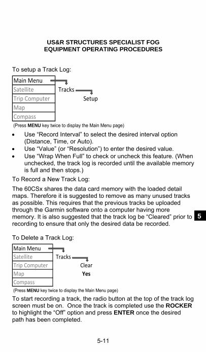
US&R STRUCTURES SPECIALIST FOG EQUIPMENT OPERATING PROCEDURES
5-11
5
To setup a Track Log: Main Menu
Satellite Tracks
Trip Computer Setup
Map
Compass(Press MENU key twice to display the Main Menu page) Use “Record Interval” to select the desired interval option
(Distance, Time, or Auto). Use “Value” (or “Resolution”) to enter the desired value. Use “Wrap When Full” to check or uncheck this feature. (When
unchecked, the track log is recorded until the available memory is full and then stops.)
To Record a New Track Log:
The 60CSx shares the data card memory with the loaded detail maps. Therefore it is suggested to remove as many unused tracks as possible. This requires that the previous tracks be uploaded through the Garmin software onto a computer having more memory. It is also suggested that the track log be “Cleared” prior to recording to ensure that only the desired data be recorded. To Delete a Track Log: Main Menu
Satellite Tracks
Trip Computer Clear
Map Yes
Compass(Press MENU key twice to display the Main Menu page) To start recording a track, the radio button at the top of the track log screen must be on. Once the track is completed use the ROCKER to highlight the “Off” option and press ENTER once the desired path has been completed.

US&R STRUCTURES SPECIALIST FOG EQUIPMENT OPERATING PROCEDURES
5-12
Using a Track Log (continued) To Save a Track Log:
(As the 60CSx has limited memory available for recording Tracks, it is suggested to remove as many unused tracks as possible. See method for this above). Main Menu
Satellite Tracks
Trip Computer Save
Map
Compass(Press MENU key twice to display the Main Menu page) The track log is saved using the current date. A different name
can be input by using the ROCKER to highlight the Name option and press ENTER.
Use the ROCKER to highlight the desired letters and press the ENTER key to input that letter or numeral.
Information (distance, number of points, and enclosed area) for the track log is presented on this page.
The units used for calculating area can be adjusted by using the ROCKER to highlight the unit and pressing ENTER.
Other options available on this page are: Show On Map – permanently displays a dotted line on the Map Display page. Delete – deletes the recorded log. Map – temporarily displays the recorded log on the Map. Track Back – provides a point by point set of directions for following the recorded track back to its origin.
Proximity Alarms
Proximity alarms can be used to alert you when you are approaching a predetermined location. From the Main Menu page, selection the Proximity icon. From the Proximity Waypoints page, highlight an empty line and press ENTER to open the Find Menu. Select the waypoint you want to set. The radius defaults to 1.0 mile but is adjustable.
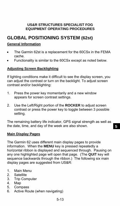
US&R STRUCTURES SPECIALIST FOG EQUIPMENT OPERATING PROCEDURES
5-13
5
GLOBAL POSITIONING SYSTEM (62st) General Information The Garmin 62st is a replacement for the 60CSx in the FEMA
cache. Functionality is similar to the 60CSx except as noted below. Adjusting Screen Backlighting If lighting conditions make it difficult to see the display screen, you can adjust the contrast or turn on the backlight. To adjust screen contrast and/or backlighting: 1. Press the power key momentarily and a new window
appears for screen contrast settings. 2. Use the Left/Right portion of the ROCKER to adjust screen
contrast or press the power key to toggle between 3 possible setting.
The remaining battery life indicator, GPS signal strength as well as the date, time, and day of the week are also shown. Main Display Pages The Garmin 62 uses different main display pages to provide information. When the MENU key is pressed repeatedly a horizontal ribbon is displayed and sequenced through. Pausing on any one highlighted page will open that page. (The QUIT key will sequence backwards through the ribbon.) The following six main display pages are suggested from US&R: 1. Main Menu 2. Satellite 3. Trip Computer 4. Map 5. Compass 6. Active Route (when navigating)
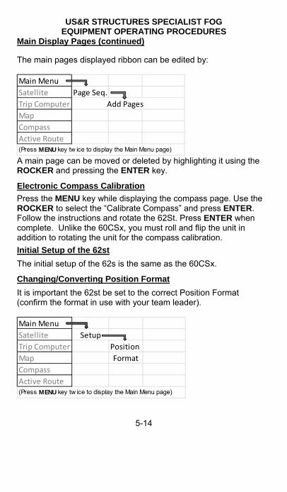
US&R STRUCTURES SPECIALIST FOG EQUIPMENT OPERATING PROCEDURES
5-14
Main Display Pages (continued) The main pages displayed ribbon can be edited by: Main Menu
Satellite Page Seq.
Trip Computer Add Pages
Map
Compass
Active Route(Press MENU key tw ice to display the Main Menu page) A main page can be moved or deleted by highlighting it using the ROCKER and pressing the ENTER key.
Electronic Compass Calibration
Press the MENU key while displaying the compass page. Use the ROCKER to select the “Calibrate Compass” and press ENTER. Follow the instructions and rotate the 62St. Press ENTER when complete. Unlike the 60CSx, you must roll and flip the unit in addition to rotating the unit for the compass calibration.
Initial Setup of the 62st
The initial setup of the 62s is the same as the 60CSx.
Changing/Converting Position Format
It is important the 62st be set to the correct Position Format (confirm the format in use with your team leader). Main Menu
Satellite Setup
Trip Computer Position
Map Format
Compass
Active Route(Press MENU key tw ice to display the Main Menu page)
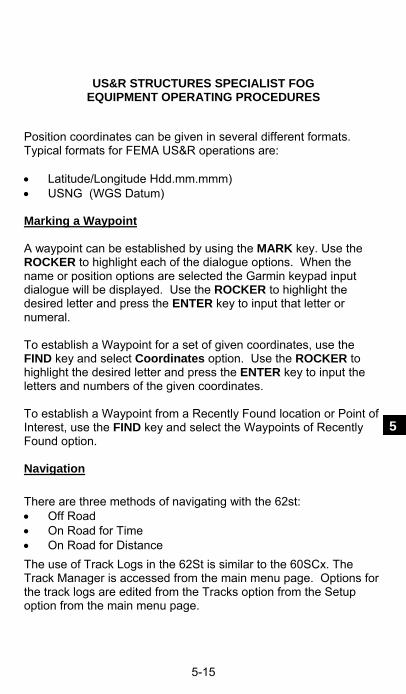
US&R STRUCTURES SPECIALIST FOG EQUIPMENT OPERATING PROCEDURES
5-15
5
Position coordinates can be given in several different formats. Typical formats for FEMA US&R operations are: Latitude/Longitude Hdd.mm.mmm) USNG (WGS Datum) Marking a Waypoint A waypoint can be established by using the MARK key. Use the ROCKER to highlight each of the dialogue options. When the name or position options are selected the Garmin keypad input dialogue will be displayed. Use the ROCKER to highlight the desired letter and press the ENTER key to input that letter or numeral. To establish a Waypoint for a set of given coordinates, use the FIND key and select Coordinates option. Use the ROCKER to highlight the desired letter and press the ENTER key to input the letters and numbers of the given coordinates. To establish a Waypoint from a Recently Found location or Point of Interest, use the FIND key and select the Waypoints of Recently Found option. Navigation There are three methods of navigating with the 62st: Off Road On Road for Time On Road for Distance
The use of Track Logs in the 62St is similar to the 60SCx. The Track Manager is accessed from the main menu page. Options for the track logs are edited from the Tracks option from the Setup option from the main menu page.

US&R STRUCTURES SPECIALIST FOG EQUIPMENT OPERATING PROCEDURES
5-16
NOTES _____________________________________________________
_____________________________________________________
_____________________________________________________
_____________________________________________________
_____________________________________________________
_____________________________________________________
_____________________________________________________
_____________________________________________________
_____________________________________________________
_____________________________________________________
_____________________________________________________
_____________________________________________________
_____________________________________________________
_____________________________________________________
_____________________________________________________
_____________________________________________________
_____________________________________________________

US&R STRUCTURES SPECIALIST FOG EQUIPMENT OPERATING PROCEDURES
5-17
5
GLOBAL POSITIONING SYSTEM (Rino 530HCx) General Information Provides a position accuracy of +/- 20 ft. under normal
conditions, +/- 10 ft with WAAS enabled. The built-in radio allows for voice communication up to 14 mi
away (line of sight). Operates with a rechargeable lithium-ion battery pack with an
A/C charger. A special clip (provided) must be used to charge the battery (do not lose). An optional 2- AA alkaline battery pack (transmitting power is limited to 2.0 W). Stored data is not lost when the batteries are removed or replaced.
Remove the battery pack on the back of the unit by turning the metal D-ring 1/4 turn ccw.
The 530HCx unit provides expanded memory through the use of a microSD card which is accessed by removing the batteries and sliding the metal locking clip toward the top of the unit.
Keypad Buttons

US&R STRUCTURES SPECIALIST FOG EQUIPMENT OPERATING PROCEDURES
5-18
Keypad Buttons (continued) The 530HCx relies more on on-screen buttons or icons than keypad buttons.
The 530HCx uses a THUMB STICK instead of a rocker and an enter button. The thumb stick is used to move a cursor around a screen, move through lists, select fields, icon, and enter data. Pressing the thumb stick activates the selection. Pressing and holding the thumb stick opens a Shortcuts Menu.
To open a display page, use the THUMB STICK to highlight the main page menu icon in the upper right corner of the screen ( ). The pages and sequencer of the pages can be modified by going to the Main Menu page and selecting Setup/Page Sequencing.
The main display pages can also be opened by using the PAGE/QUIT key located below the large TALK button located on the left side of the unit. This key is also used to quit or back out of a selection.
With the exception of the Main Menu page, one can select options for opened page by using the Option Menu button at the upper right of the screen. To close a feature or setting page, the Close button (located in the upper right corner of the screen) can be selected or use the PAGE/QUIT key.
Start-Up and Satellite Acquisition
Before turning the 530HCx on, find a location that provides a clear view of the sky and allow for the acquisition of a proper number of satellites.
To turn on the 530HCx, press and hold the POWER key located on the top of the instrument between the two antenna posts. At least three satellites are required to provide 2-dimensional location information and four are required to provide 3-dimensional (Lat-Long-Elevation) location.
The two circles on the satellite page represent satellites located on the horizon (outer circle) and 45-degrees from the current position (inner circle).
Once a sufficient number of satellites have been located, the accuracy of the position data will be provided at the top left of the Satellite Status Page.

US&R STRUCTURES SPECIALIST FOG EQUIPMENT OPERATING PROCEDURES
5-19
5
If no satellites can be acquired, a dialog box will appear that requests if the user desires to use the 530HCx indoors. This provides limited functionality for position but enables the unit to be loaded with maps and waypoint sets. With the Satellite Status Page Options displayed, use the THUMB STICK keypad to highlight “Use With GPS Off” and press the THUMB STICK keypad.
To turn the 530HCx off, press and hold the power key. Adjusting Screen Contrast and Backlighting
If lighting conditions make it difficult to see the display screen, you can turn on the backlight by momentarily pressing the POWER key. Pressing the POWER again, causes a pop-up window to appear that allows adjustment of the backlighting brightness with the THUMB STICK. Use the PAGE/QUIT key to exit.
Main Display Pages The 530HCx uses different main display pages to display information. With the exception of the Mail Menu page, page options can be changed by selecting Menu-Option on-screen button to the left of the main page menu button. Six pages are suggested for US&R operations:
1. Satellite Page – Provides the satellite signal status. Three satellites are required for a two-dimensional fix (no altimeter) and four satellites are required for a three-dimensional fix.
2. Trip Computer Page – Provides trip and navigation data such as Trip Odometer, Maximum Speed, and Elevation. The fields can be changed by highlighting the field and selecting from the list options using the THUMB STICK.
3. Map Page – Provides a detail map of the area surrounding the current location. Detailed maps are provide by preloading them using MapSource.
4. Compass Page – Provides an electronic graphical compass and indicates direction to go and direction of travel.
5. Main Menu – This page provides a directory of advanced features and settings.

US&R STRUCTURES SPECIALIST FOG EQUIPMENT OPERATING PROCEDURES
5-20
Main Display Pages (continued)
6. Radio Page – This page allows communication with other radio units as well as sending and receiving position information of other 530HCx units. Channels and squelch codes are selected at this page. The unit defaults to this page upon power-up.
To add or delete main display pages: Main Menu
Satellite Setup
Trip Computer Page Sequence
Map
Compass
Radio(Press Page/Quit key to display the Main Menu page)
Additionally, when the 530HCx is navigating, the Active Route page is displayed and is part of the page sequence. Information on this page is presented dependent on the type of navigation:
1. If “Follow Roads” or “Shorter Distance” is selected for
navigation, the Turn by Turn route page is displayed. The THUMB STICK can be used to highlight each leg of the route. Pressing the THUMB STICK key displays the turn associated with that leg.
2. If the “Off Road” option was selected for navigation (over Land, Sea or Air) the Electronic Compass page is displayed indicating required and current heading. When you are traveling off course the inner arrow (indicating required heading) will point in a different direction.
3. The internal electronic compass of the 530HCx will only work when it is actually turned on. Otherwise it will only relate your moving position. Therefore when the compass is off you must travel at least ten feet in order for the unit to provide accurate heading information.

US&R STRUCTURES SPECIALIST FOG EQUIPMENT OPERATING PROCEDURES
5-21
5
Electronic Compass Calibration
While at the Compass page, click on the Option Menu icon and select the Calibrate Compass option. The device must be slowly rotated in a horizontal plane two times.
Initial Setup of the 530HCx There are several options that should be set or checked prior to using the 530HCx: Ensure that WAAS is enabled: Main Menu
Satellite Setup
Trip Computer System
Map WAAS
Compass Enabled
Radio(Press Page/Quit key to display the Main Menu page) Turn of key beep (this will turn of the key beep option and help to conserve battery life):
Main Menu
Satellite Setup
Trip Computer Tones
Map Key Beep
Compass Off
Radio(Press Page/Quit key to display the Main Menu page)

US&R STRUCTURES SPECIALIST FOG EQUIPMENT OPERATING PROCEDURES
5-22
Initial Setup of the 530HCx (continued) Set map page orientation North Up:
Main Menu
Satellite Setup
Trip Computer Map
Map Orientation
Compass Track Up
Radio(Press Page/Quit key to display the Main Menu page) Set Local Time Zone: Main Menu
Satellite Setup
Trip Computer Time
Map Time Zone
Compass
Radio(Press Page/Quit key to display the Main Menu page) The Time Format can also be set at this menu (12-hr vs. 24-hr).
Changing/Converting Position Format
It is important the 530HCx be set to the correct Position Format (confirm the format in use with your team leader). Main Menu
Satellite Setup
Trip Computer Units
Map Position Map
Compass Format Datum
Radio(Press Page/Quit key to display the Main Menu page)

US&R STRUCTURES SPECIALIST FOG EQUIPMENT OPERATING PROCEDURES
5-23
5
Position coordinates can be given in several different formats. Typical formats for FEMA US&R operations are: Latitude/Longitude (Hdd.mm.ss or Hdd.mm.mmm) USNG
The correct Map Datum must also be selected. WGS84 is used for for both Lat/Long and USNG. Marking a Waypoint To establish a Waypoint for your current position, push and hold the THUMB STICK to reveal the Shortcuts window, select Mark Waypoints (can also Mark from the Main Menu page). Edit the displayed information as required and select OK. To establish a Waypoint for a set of given coordinates, mark a waypoint for the current position as described above and edit the coordinates as required using the THUMB STICK. To establish a Waypoint from a Recently Found location or Point of Interest, push and hold the THUMB STICK to reveal the Shortcuts window, select Find, and then select either Recent Find or All Points of Interest. (The Find option can also be selected from the Main Menu page.) Navigation There are three methods of navigating with the 530HCx: Following Roads by Fastest Time Following Roads by Shorter Distance Off Road (Land, Sea or Air)
The 530HCx will navigate to several types of locations. Without MapSource detailed maps installed, the 530HCx can navigate to Cities, Interstate Exits, Waypoints, and Recently Found places. With MapSource detailed maps installed; Points of Interest, Addresses, or Intersections are also available.

US&R STRUCTURES SPECIALIST FOG EQUIPMENT OPERATING PROCEDURES
5-24
Navigation (continued)
To navigate to any of the above mentioned locations, press and hold the THUMB STICK and select FIND or use the Main Menu page:
Main Menu
Satellite Find
Trip Computer Select
Map Type Select
Compass POI
Radio(Press Page/Quit key to display the Main Menu page) Press the button to the right of the THUMB STICK to zoom in
close enough to see the route. If either of the Follow Road options was selected, and the
detailed maps for that area are not installed, there may be a significant gap in the routing directions shown on the Map page.
Select the Active Route page to display the turn by turn directions for the Follow Road route.
If the Off Road preference was selected a dark line will appear on the Map page indicating the course you should follow.
Traveling direction is indicated by the small black arrow located in the Map page.
The 530HCx compass is only activated while the unit is moving. It is suggested to move in one straight line for approximately ten feet noting the direction of the black arrow.
Try to align direction of travel (the tip of the black arrow) to the dark line displayed.
a. If “Follow Roads” or “Shorter Distance” is selected for navigation, the Turn by Turn route page is displayed. The THUMB STICK can be used to highlight each leg of the route. Pressing the THUMB STICK key displays the turn associated with that leg.

US&R STRUCTURES SPECIALIST FOG EQUIPMENT OPERATING PROCEDURES
5-25
5
b. If the “Off Road” option was selected for navigation (over Land, Sea or Air) the Electronic Compass page is displayed indicating required and current heading. When you are traveling off course the inner arrow (indicating required heading) will point in a different direction.
The internal electronic compass of the 530HCx will only work when it is actually turned on. Otherwise it will only relate your moving position. Therefore when the compass is off you must travel at least ten feet in order for the unit to provide accurate heading information.
Select the Compass page. The dark arrow displayed indicates the direction of travel to reach desired location. Again it is suggested to move in one straight line for approximately ten feet noting the direction of the black arrow.
Using a Track Log
The path that the 530HCx unit takes can be recorded as a Track Log (bread crumb trail) and includes information about points along the path, including time and position. This is accomplished by the 60CSx automatically recording its position at predefined intervals of time or distance. This feature is very useful for documenting travel in a given time period. (i.e. houses searched in a neighborhood for a specific day).
The track log can also be used to measure the area of any space encompassed by a path as well as retracing or Tracking Back along a recorded path.
The 530HCx has memory for 20 separate saved track logs with 500 points each. The memory used for each depends on the preselected recording intervals. The interval chosen should depend on the anticipated amount of overall travel. For example: Searching a two-mile square area encompassing several city streets for the entire day may best be recorded using Time at an interval of five minutes. While documenting a city block area encompassing a large debris pile may best be recorded using Time at an interval of 5-seconds.

US&R STRUCTURES SPECIALIST FOG EQUIPMENT OPERATING PROCEDURES
5-26
Using a Track Log (continued)
To setup a Track Log: Main Menu
Satellite Tracks
Trip Computer Setup
Map
Compass
Radio(Press Page/Quit key to display the Main Menu page) Use “Record Method” to select the desired interval option
(Distance, Time, or Auto). Use “Interval” to enter the desired value. Use “Wrap When Full” to check or uncheck this feature. (When
unchecked, the track log is recorded until the available memory is full and then stops.)
To Record a Track Log:
The 530HCx shares the data card memory with the loaded detail maps. Therefore it is suggested to remove as many unused tracks as possible. This requires that the previous tracks be uploaded through the Garmin software onto a computer having more memory. It is also suggested that the track log be “Cleared” prior to recording to ensure that only the desired data be recorded.
To Delete a Track Log: Main Menu
Satellite Tracks
Trip Computer Clear
Map Yes
Compass
Radio(Press Page/Quit key to display the Main Menu page) To start recording a track, the radio button at the top of the track log screen must be on. Once the track is completed use the THUMB STICK to highlight the “Off” option.

US&R STRUCTURES SPECIALIST FOG EQUIPMENT OPERATING PROCEDURES
5-27
5
To Save a Track Log: Main Menu
Satellite Tracks
Trip Computer Save
Map
Compass
Radio(Press Page/Quit key to display the Main Menu page)
The track log is saved using the current date. A different name
can be input by using the THUMB STICK to highlight the Name option.
Use the THUMB STICK to highlight the desired letters and press the THUMB STICK to input that letter or numeral.
Information (distance, number of points, and enclosed area) for the track log is presented on this page.
The units used for calculating area can be adjusted by using the THUMB STICK to highlight the unit and pressing the THUMB STICK.
Other options available on this page are: Show On Map – permanently displays a dotted line on the Map Display page. Delete – deletes the recorded log. Map – temporarily displays the recorded log on the Map. Track Back – provides a point by point set of directions for following the recorded track back to its origin.

US&R STRUCTURES SPECIALIST FOG EQUIPMENT OPERATING PROCEDURES
5-28
Using the Radio Features The 530HCx allows voice communication between units as well as transmitting one’s location and receiving contact information from other units. Two types of radio frequencies are available: GMRS – General Mobile Radio Service (Channels 1-7, 15-22) FRS – Family Radio Service (Channels 8-14) The use of the GMRS frequencies is regulated by the Federal Communications Commission and requires a license. The GMRS frequencies on the 530HCx can broadcast with a maximum 5 Watts with up to 14 miles line of sight distance. The FRS is generally unregulated and requires no license to use. Its broadcast distance is limited as the maximum output is 0.5 Watts. There are 8 repeater channels (disabled by default) for use with an operating repeater (Channels 15R-22R). The repeater channels will not broadcaster peer-to-pear position information. Each 530HCx frequency has 38 squelch codes. These codes allow the 530HCx to filter out other traffic on a frequency making communication easier. Note that the squelch codes are not a scrambling system so your communications can be heard by all on the same frequency. Set the squelch code to zero to hear all the activity on the selected channel. However, you must be set to the same code as the other unit to transmit back. To change the channel and code, highlight and select either the channel or code with the Thumb Stick and select the desired value from window list that appears. The 530HCx remembers the same channel-code combination as the channels are changed. Volume and squelch is controlled by pressing the button to the left of the Thumb Stick.

US&R STRUCTURES SPECIALIST FOG EQUIPMENT OPERATING PROCEDURES
5-29
5
The 530HCx does allow for secure communications. This is accomplished by turning on “Scramble” on the Radio Setup screen. Both units must be set up identically for the two units to communicate. Peer-to-Peer Positioning: A useful feature of the 530HCx is its ability to transmit its position to other 530HCx units (positioning is updated every 30 seconds or when the Call key is pressed). If this option is selected, your user symbol will appear on the map page of other units that have given permission to be added to their contact list. To enable position information to be sent from your unit: Radio
Main Menu Setup
Satellite Send Location
Trip Computer Yes
Map
Compass(Press Page/Quit key to display the Main Menu page) When a signal is first received from another 530HCx unit, a New Contact page will appear. By selecting MAP, the new contact will appear on your Map page. To navigate to a contact, select the contact from the list on Map page and select GO TO.

US&R STRUCTURES SPECIALIST FOG EQUIPMENT OPERATING PROCEDURES
5-30
GARMIN MAPSOURCE® SOFTWARE Necessary to interface a Garmin GPS unit (including the GPS
60CSx, 62st, and 530HCx ) with a computer.
Used to upload geographical date, such as detailed maps, as well as downloading waypoints, routes, tracks, and associated information obtained in the field.
Data transfer is via a USB cable or storage card.
Various mapping products are available for use with MapSource and include: - City Select - City Navigator (more detailed than City Select) - BlueChart - USA TOPO
The following information is provided primarily for the City Select mapping product (see p. 5-37 for typical MapSource window display with the City Select – North America product).
Comments on the Use of Gramin Software
Most of the Garmin software must be unlocked with a 25-digit code in order for it to be installed on a computer.
Uploading of information to a Garmin GPS unit should be done prior to mobilization, if at all possible.
Graphic Maps The Graphic Map is the display of the currently selected geographical information within MapSource. The view can be changed by either zooming in or out, or by panning in all directions. These view changes can be done using the on-screen scroll bars, the keyboard’s arrow keys, or the Hand tools.
Creating Map Sets Geographical information must be contained in a Map Set in order be uploaded to a GPS unit. A Map Set is one or more detailed area maps that have been selected from the Graphic Map. City Select divides the United States into detailed area maps of varying geographical size depending on the population and development densities. To create a Map Set in MapSource:

US&R STRUCTURES SPECIALIST FOG EQUIPMENT OPERATING PROCEDURES
5-31
5
1. Select a zoom scale that allows viewing of the map area
boundaries.
2. Select “Map” from the Tools menu or the “Map” tool icon in the Tools toolbar. The map area boundaries will be outlined in yellow when the Map tool is located with a detailed map.
3. Click the left mouse key in the selected area. To select several map areas, drag the mouse to draw a box through the different areas. Selected map areas are shaded in pink.
4. Selected map areas are given in listed in the Maps tab on the left of the screen along with the memory requirements for each map area.
5. Ensure that the total member requirement, given at the bottom of the Map tab does not exceed the memory capacity of the GPS unit (Garmin 60CS = 56 Mb, Garmin 60CSx = func of storage card).
6. Save Map Set by selecting “Save” in the File menu. Map Sets, along with associated waypoints, routes, etc., are saved as GPS data files have the .gdb file extension.
Creating a Waypoint on the Graphic Map
Waypoints can be created within the MapSource program using geographical information for later uploading to a GPS unit:
1. Select “Waypoint” from the Tools menu or the “Waypoint” tool icon in the Tools toolbar.
2. Position the mouse pointer at the desired location for the waypoint on the Graphic Map.
3. Left-click the mouse, or right-click the mouse and select “New Waypoint.” In either case, the “Waypoint Properties” dialog box will open.
4. Make any desired changes to the “Waypoint Properties,” then click “OK” to save the new waypoint.
US&R STRUCTURES SPECIALIST FOG EQUIPMENT OPERATING PROCEDURES
5-32
Creating a Waypoint using Know Coordinates
A waypoint can be created within the MapSource program using known coordinates of a location for later uploading to a GPS unit:
1. Select “Waypoint” for the Tools menu. The “Waypoint Properties” dialog box will open.
2. Edit the waypoint name and enter a description, if desired. Note that Garmin GPS units can only display a limited number of characters. Names that are too long are truncated for display on the GPS unit. Other properties of the waypoint can also be edited.
3. Enter the coordinates of the new waypoint. Only a single space is used to separate the N and E decimal coordinates.
4. The new waypoint can be shown on the Graphic Map by clicking the “Show on Map” key at bottom right of dialog box.
5. Click “OK” to record the waypoint. Waypoint Right-Click Menu The following options may appear by clicking the right mouse key on a waypoint on the Graphic Map or a waypoint in the Waypoints tab list:
Move Waypoint – Activates the Selection tool and allows you to move selected waypoint to another location on the Graphic Map.
New Waypoint, Begin Route, Begin Measurement, Find Nearest Places – for finding places and creating routes.
Remove Waypoint from Route – Selecting this option removes the selected waypoint from the route, but does not delete the waypoint (if waypoint is a route waypoint).
Cut/Copy/Paste – Allows one to cut, copy, and paste waypoints from one active MapSource document to another.
Delete Waypoint – Delete the selected waypoint
Show Selected Waypoint on Map – Zooms to the selected waypoint and centers it on the Graphic Map.
Waypoint Properties – Activate the “Waypoint Properties,” allowing for their review and editing for the selected waypoint.
US&R STRUCTURES SPECIALIST FOG EQUIPMENT OPERATING PROCEDURES
5-33
5
Creating Routes
Routes can be created in MapSource for uploading to a GPS unit. Routes are either direct (straight-line) or an automatic route (turn-by-turn) (default for City Select).
1. Select “Route” from the Tools menu or the “Route” tool icon in the Tools toolbar.
2. Click on waypoints or map locations on the Graphic Map in the sequence required for the route. If a waypoint does not exist on the map, a new waypoint will be created. Route legs are created as direct lines between waypoints.
3. After end point of route has been entered, press Esc or right-click the end point and select “Cancel.” The route is created and automatically named using the names of the first and last waypoints.
4. The total distance of the route is given in Route tab list.
5. Properties of the route can be edited by right-clicking the route in the Route tab list and selecting “Route Properties…”
Determining Distance/Bearing Between Two Waypoints The straight-line distance and bearing between two points can be determined using MapSource:
1. Select “Distance/Bearing” from the Tools menu or the “Distance/Bearing” tool icon in the Tools toolbar.
2. Click on the point of origin waypoint or map location then move mouse cursor to termination point. Distance and bearing to the termination point is displayed at the bottom of the MapSource window.
3. By clicking on the termination point, additional points can be added but the bearing is measured from the beginning point while the distance is measure along the series of segments

US&R STRUCTURES SPECIALIST FOG EQUIPMENT OPERATING PROCEDURES
5-34
Transferring MapSource Date to a GPS Unit
Map Sets, with their associated waypoints, routes, and tracks can be uploaded to a Garmin GPS unit (or storage card) from the MapSource program: 1. Attach USB cable between computer and GPS unit. 2. Select “Save To Device …” in the Transfer menu or
click on the “Send To Device” icon in the Tools toolbar and choose the device type. A different dialog box will appear depending on the attached GPS unit.
3. In the “What to Save” dialog box, select the date type for
transfer by placing a check mark in the box(es) next to the type of data to be transferred.
4. If saving to a storage card, select the drive letter in the
“Storage Card Reader” dialog box. 7. Click “Save” to begin transfer of data. The GPS unit can
automatically turned off upon completion of the date transfer by placing a check mark in the box just above the “Save” key.
Note: Map Sets currently saved on Garmin GPS unit are replaced with the new Map Sets.

US&R STRUCTURES SPECIALIST FOG EQUIPMENT OPERATING PROCEDURES
5-35
5
Transferring MapSource Date from a GPS Unit
Maps, waypoints, routes, and tracks can be downloaded from a Garmin GPS unit (or storage card) to the MapSource program:
1. Attach USB cable between computer and GPS unit.
2. Select “Receive From Device …” in the Transfer menu or click on the “Receive From Device” icon in the Tools toolbar and choose the device type. A different dialog box will appear depending on the attached GPS unit.
3. In the “What to Save” dialog box, select the date type for transfer by placing a check mark in the box(se) nest to the type of data to be transferred.
4. If transferring from a storage card, select the drive letter in the “Storage Card Reader” dialog box.
5. Click “Save” to begin transfer of data. The GPS unit can automatically turned off upon completion of the date transfer by placing a check mark in the box just above the “Save” key.
Real-Time Tracking MapSource can read information for a GPS unit in real time. The location of the GPS unit is shown as a red triangle on the Graphic Map, tracking data is displayed on the GPS tab and the track is recorded.
1. Attach serial or USB cable between computer and GPS unit.
2. Set the “USB Data Format” on the GPS unit to either Garmin or NMEA format.
3. Select the GPS tab in MapSource and click “Select Device.” Select the proper connection type.
4. Check the “Record Track” box and MapSource will begin to track the movement of the GPS unit.
5. To have MapSource automatically adjust the Display Map to keep the GPS unit visible on the Graphic Map, check the box next to “Keep Vehicle Visible on Map.”

US&R STRUCTURES SPECIALIST FOG EQUIPMENT OPERATING PROCEDURES
5-36

US&R STRUCTURES SPECIALIST FOG EQUIPMENT OPERATING PROCEDURES
5-37
5
TOTAL STATION (Nikon NPL-352 or Nivo 5M) A Total Station measures distances, horizontal and vertical
angles, and can determine XYZ coordinates. This capability allows for the monitoring of a building’s movement over time.
Distances of approximately 300 ft. can be measured without the need for a prism at the point measured. The surface of the point measured will influence the maximum range. Greater range can be obtained using a prism or a reflector-type target.
Some keys have menus specific to their function. These menus can be shown by pressing the key in question down for 3 seconds. Nikon refers to these keys as "1-second keys".
Sometimes options are given in the display on the keyboard. These options appear at the bottom of the screen and can be selected by pressing one of the white keys below the screen. These are called "soft keys" by Nikon.
The display window of the total station is configured to show four different combinations of data. Nikon calls these the Basic Measurement Screens (BMS). The screens are indexed in the upper right corner as 1/4, 2/4, 3/4 and 4/4. Most applications of the total station for US&R purposes use screen 4/4, which displays the XYZ coordinates. Pressing the DSP key toggles between the different BMS screens. The up and down cursor keys can also be used to navigate through the BMS screens.
Initial Setup Procedure
1. Set the tripod at a proposed station location without the total station attached:
- With the legs together, extend them to chin height.
- Spread the legs so tripod mounting surface is approx. level.
- Set the far leg first, spacing the other two legs to level.
- Snugly fasten all the leg clamps, but do not over-tighten.
2. Remove the total station from the carrying case and mount it on the tripod. Insert the tripod mounting screw into the center hole of the base plate of the instrument, and snugly fasten the screw, but do not over-tighten.

US&R STRUCTURES SPECIALIST FOG EQUIPMENT OPERATING PROCEDURES
5-38
Nikon NPL 352 Initial Setup Procedure (continued)
3. Level the total station by loosening a tripod leg clamp and adjusting the leg length until the air bubble is in the center of the circular level, (bull’s-eye level). Lengthening a leg moves the bubble towards that leg.
4. The total station can be leveled further by using the procedure described in the Leveling section below (see page 5-45).
5. Turn on the total station by pressing the PWR key. The Tilt Telescope screen will appear showing the current date and time, and the last values set for temperature and pressure.
6. Tilt the telescope to initialize the vertical angle.
7. Check the level compensators screen by pressing the 0 key (the screen will appear automatically whenever the instrument is out of level by 3 minutes or more). The level compensators electronically adjust the measurements made by the total station if it is out of level by less than 3 minutes. Return to the BMS by pressing the ESC key
8. Focus the telescope cross hairs by adjusting the smaller knurled ring of the eyepiece. This provides consistent sighting of targets (also see Sighting section below, page 5-46).
Creating a New Job
To generate a grid in the total station, a new Job must be created:
1. Press the MENU key and select “1.Job” by pressing the 1 key (or scroll to highlight “1.Job” and press the REC/ENT key) to get to the Job Manager screen. A new Job is created by pressing the softkey (the white MSR1 key) under “Creat” on the Job Manager screen to get to the Create Job screen.
2. Each Job requires a unique name. Use the default Job name which appears in the Create Job screen (the date YYMMDD followed by a dash and a sequential digit). Press the REC/ENT key once. Read what is written on the screen.
3. Press the softkey (the white MSR2 key) under “Sett” to get to the Job Settings screen.

US&R STRUCTURES SPECIALIST FOG EQUIPMENT OPERATING PROCEDURES
5-39
5
Creating a New Job (continued)
The job settings can only be changed at this time. The default settings suggested for US&R use are:
Scale: 1.000000 T-P corr: ON Sea Level: OFF C&R Corr: 0.132 Angle: DEG Distance: US-Ft (Decimal-Ft) Temp: ºF Press: inHg VA zero: Zenith AZ zero: North Order: ENZ HA: Azimuth
Use the left and right scroll keys to change an incorrect setting. Press REC/ENT after each setting is verified. After pressing the REC/ENT key for HA: Azimuth, you return to the BMS, completing the creation of the new Job.
4. Now check the coordinate ordering and labeling convention. Press the MENU key and select “3.Settings” by pressing the 3 key. Select “3.Coord.” by pressing the 3 key again. Order should be set to “ENZ”, Label should be set to “XYZ” and AZ zero should be set to “North”. Press REC/ENT after each setting is verified. After pressing the REC/ENT key for AZ zero, you return to the Settings screen.
5. While still on the Settings screen, check the data recording format. Select “8.Rec” by pressing the 8 key. Store DB should be set to “RAW+XYZ”, and Data Rec should be set to “Internal”. Press REC/ENT after each setting is verified. After pressing the REC/ENT key for Data Rec, you return to the Settings screen. Press the ESC key to return to the MENU screen. Press the ESC key again to return to the BMS.

US&R STRUCTURES SPECIALIST FOG EQUIPMENT OPERATING PROCEDURES
5-40
Creating a New Job (continued) 6. Configure the MSR1 and MSR2 keys. These settings can be
changed at any time. Hold the MSR1 key down for 3 seconds to enter/check settings, then repeat for the MSR2 key:
MSR1: Target: Prism Prism Constant: 18mm (or for prism used) Mode: Precise AVE: 3 REC MODE: MSR only MSR2: Target: N-Prism Prism Constant: 0 Mode: Normal AVE: 1 Rec mode: MSR only
Press REC/ENT after each setting is verified. After pressing REC/ENT for Rec mode, you return to the BMS screen.
Creating a New Grid (relative to the center of the total station)
1. Having set up the total station as described previously and having created the new Job, the new Grid can be created. A known point and an orientation of the grid are required to establish the new Grid. The coordinates of the known point and the orientation of the grid are entered into the Job by creating a new Station.
2. Establish the center of the instrument as the new Station. Press the STN key (the 7 key). Select “1.Known” by pressing the 1 key. Number this Station as 1 (ST: 1), then press REC/ENT. Input assumed coordinates for the new Station (use X = 1000 ft, Y = 100 ft, and Z = 10 ft) and press REC/ENT after entering each coordinate. The cursor will skip to the CD line. Leave it blank and press REC/ENT to return to the Input Station menu.

US&R STRUCTURES SPECIALIST FOG EQUIPMENT OPERATING PROCEDURES
5-41
5
Creating a New Grid (continued)
3. Enter the height of instrument as zero (HI: 0), press REC/ENT.
4. The next screen displayed is the Backsight (BS) screen. A BS is used to orient the grid. Select “2.Angle” by pressing the 2 key. This brings you to the Input BS Point screen. Number the BS as 9, press REC/ENT. Enter zero for the height of the target (HT: 0), press REC/ENT. This brings you to the Input BS Angle screen. Enter zero for the azimuth angle (AZ: 0), press REC/ENT. Now the orientation of the total station must be established. For US&R use, select a BS point that is forward of the total station (towards the building being monitored). Sight through the telescope so the line of sight is approximately perpendicular to the face of the building to be monitored (this will roughly align the X Y grid with the building layout) and press REC/ENT. This returns you to the BMS. It is not necessary to measure the location of the BS point as it is only used for the initial orientation of the grid.
5. The instrument can now measure and record point coordinates.
Sighting and Measuring 1. Loosen both the horizontal and vertical tangent screws. 2. Ensure that the telescope focuses properly. (See page 5-46). 3. Use the optical sight on top of the telescope to roughly point
the telescope at the target. 4. Snug the horizontal tangent screw. Do not over tighten. 5. Look through the eyepiece and move the telescope vertically
until the target is in view. 6. Snug the vertical tangent screw. Do not over tighten.

US&R STRUCTURES SPECIALIST FOG EQUIPMENT OPERATING PROCEDURES
5-42
Sighting and Measuring (continued) 7. Rotate the focusing ring to bring the target into sharp focus on
the eyepiece crosshairs. 8. While looking through the telescope, use the horizontal and
vertical tangent screws to sight the telescope crosshairs on the center of the target.
9. Press either MSR1 or MSR2 to take measurement. MSR1 is
for measurements to a reflector (prism), MSR2 is for reflectorless measurements. MSR2 is used most of the time.
10. When the X, Y, Z coordinates are displayed on BMS Screen
4/4, press the REC/ENT key. The Record PT screen is displayed; this is where the point number can be changed.
11. Use the default Point Number (PT) shown or scroll up to the PT line and enter a new number, press REC/ENT. Unless using a prism on a pole, leave the Height of Target (HT: 0.00) as zero, press REC/ENT. The cursor will move to the CD line. Leave it blank and press REC/ENT. The point has been recorded in the memory of the total station and you are returned to the BMS ready to measure the next point.
12. The data for recorded points can be viewed in the DAT screen.
Press the DAT key (the 6 key). Scroll to the point you want to view and press REC/ENT. Exit this screen by pressing the ESC key. This returns you to the point list screen. Exit this screen by pressing the ESC key. The DAT screen data format can be changed. Starting in the BMS screen, hold the DAT key (the 6 key) down for 3 seconds to enter/check the data reporting format. The format should be “3.XYZ data". Change it to “3.XYZ data" by pressing the 3 key. If it is already set to “3.XYZ data" use the ESC key to exit out of this option. If you change it from another option you are taken directly to the XYZ data screen. Exit this screen by pressing the ESC key.
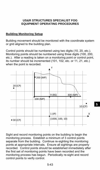
US&R STRUCTURES SPECIALIST FOG EQUIPMENT OPERATING PROCEDURES
5-43
5
Building Monitoring Setup Building movement should be monitored with the coordinate system or grid aligned to the building plan. Control points should be numbered using two digits (10, 20, etc.). Monitoring points should be numbered using three digits (100, 200, etc.). After a reading is taken on a monitoring point or control point, its number should be incremented (101, 102, etc. or 11, 21, etc.) when the point is recorded.
20 (CP)
30 (CP)
1 (IP)
10 (CP)
300 (MP)
100 (MP)
200 (MP)
9 (BS)
X
Y
(1000, 100, 10)
Sight and record monitoring points on the building to begin the monitoring process. Establish a minimum of 3 control points separate from the building. Continue re-sighting the monitoring points at appropriate intervals. Ensure all sightings are properly recorded. Control points should be established immediately after the first set of monitoring points have been recorded and the monitoring process has begun. Periodically re-sight and record control points to verify control.

US&R STRUCTURES SPECIALIST FOG EQUIPMENT OPERATING PROCEDURES
5-44
Creating a New Station within an Existing Coordinate System
There are several methods available to move the total station to a new location on a grid and then tie it back into that same grid. These methods are accessed by pressing the STN key (the 7 key) and then selecting a method from a list of options. One method is recommended below for US&R building monitoring.
Option No. 7 – Known Line Method. This method uses any two points which can be seen from the new location, and whose grid coordinates are known, to establish where the total station is on the existing grid. The Known Line Method generically refers to these two points as P1 or PT1, and P2 or PT2.
1. Set up and level the total station at a new location. It is not necessary to establish this location as a permanent Instrument Point (IP) but only to use the center of the total station as a temporary Instrument Point. Given this, the HI is zero (HI = 0).
2. After pressing the STN key (the 7 key), select the option “7.Known Line” by pressing the 7 key again. This brings you to the Input PT1 screen.
3. Input the point number of the known point to be used for PT1 and press REC/ENT. If the known point is recorded within the current Job, the recorded coordinates will be shown. Press REC/ENT to accept these coordinates. If it has not been previously recorded, input the point’s coordinates and press REC/ENT after entering each coordinate. Enter HT = 0.0 if sighting the point directly (enter the target height if using a prism on a pole). Press REC/ENT. The cursor will move to the CD line. Leave the CD line blank and press REC/ENT to return to the Input PT1 screen.
5. The known point used as PT1 must now be sighted and measured. Sight the point and press MSR2 (MSR1 if using a prism) and then press REC/ENT after the instrument has completed the distance measurement.

US&R STRUCTURES SPECIALIST FOG EQUIPMENT OPERATING PROCEDURES
5-45
5
Option No. 7 – Known Line Method (continued)
6. Select option “1.By Coord” by pressing the 1 key.
7. Input the point number of the known point to be used for PT2. If the point has already been recorded in the current Job, it’s coordinates will be shown after REC/ENT is pressed. Otherwise, input the point number, press REC/ENT, enter the known point coordinates, and press REC/ENT after each entry.
8. Enter the target height (HT = 0.0 if sighting a point directly). Press REC/ENT.
9. Sight the point and press MSR2 (MSR1 if using a prism) and then press REC/ENT after the instrument has completed the distance measurement.
10. The new location of the instrument is now shown in the display screen. Press REC/ENT to record this point’s coordinates.
11. A default station number is displayed. Erase that number and enter a number for this point and press REC/ENT. We are using the center of the total station as the position of the point, so enter HI = 0.0 and press REC/ENT. Leave the CD line blank and press REC/ENT. The cursor moves to the BS line, which displays the point number of the known point used for PT1. Accept this by pressing REC/ENT.
12. The total station is now oriented on the original coordinate grid. Leveling – (Additional)
1. Un-snug the horizontal tangent screw.
2. Rotate the alidade until the plate level is parallel with any two of the three leveling posts.
3. Use these two leveling posts to move the bubble to the center of the level. Note: bubble moves in the direction of left thumb.
4. Rotate the alidade approximately 90° and use the third post to move the bubble into the center of the level. Do not move either of the other two posts while adjusting the third post.

US&R STRUCTURES SPECIALIST FOG EQUIPMENT OPERATING PROCEDURES
5-46
Sighting Adjustments
To measure distances accurately, the total station must be properly adjusted and focused on the target.
- To bring the telescope crosshairs into sharp focus, aim the telescope at a blank area, such as a piece of paper. Look through the telescope and adjust the smaller knurled ring of the eyepiece until the crosshairs are in sharp focus.
- To check for parallax, sight the telescope at the target image. Rotate the focusing ring (largest ring between the eyepiece and the telescope body) to bring the target image into sharp focus on the crosshairs. Move your eye vertically and laterally to see if the target image moves relative to the crosshairs. Readjust the eyepiece if relative movement is detected.
Menu Key
The MENU screen is used to access important functions and settings of the Total Station. To display the MENU screen, press the MENU key. The following options are given in the MENU screen:
1. Job (Job Manager) – Used to create and manage stored jobs.
2. Cogo – Coordinate geometry calculations.
3. Settings – Used to change various settings (use the left or right arrow keys (◄/►) to toggle between the available selections.
4. Data – Used to view data (Use DSP to view toggle between RAW and XYZ data).
5. Comm. (Communication) - Transfer data to and from a computer.
6. 1sec Keys – several keys (illumination key, REC/ENT, MSR1, MSR2, DAT and DSP) have menus or additional functionality if held down for longer than1 second.
7. Calibrat. (Calibration) – Used to make corrections to the instrument to assure correctly measured data.
8. Time – Edit date and time.

US&R STRUCTURES SPECIALIST FOG EQUIPMENT OPERATING PROCEDURES
5-47
5
Instrument Handling
Always carry the instrument in its case.
Do not carry the instrument from the top handle.
When leaving the instrument set up, place the lens cap on and cover the whole instrument with the vinyl cover.
Protect the instrument against the weather.
During transportation always place accessories in their correct position to prevent displacement.
Drying a wet instrument
Wipe the total station carefully, remove the foam inserts from the case and let them dry out completely.
Allow the total station to air-dry before it is returned to its case. This prevents the telescope optics from fogging.
Nikon NPL 352 Keyboard and Display

US&R STRUCTURES SPECIALIST FOG EQUIPMENT OPERATING PROCEDURES
5-48
Nikon NPL 352 Keyboard and Display (continued)

US&R STRUCTURES SPECIALIST FOG EQUIPMENT OPERATING PROCEDURES
5-49
5

US&R STRUCTURES SPECIALIST FOG EQUIPMENT OPERATING PROCEDURES
5-50
Nikon Nivo 5M - Replacement Total Station for the NPL-352 The Nivo 5M is very similar to the NPL-352 with the exception of the following:
- The Nivo 5M is smaller and lighter than the NPL 352. - Under ideal conditions, the maximum measured distance
is 900 ft for reflectorless mode. - The Nivo 5M uses two batteries, which allows for replacing
batteries without turning the total station off. - There is only one face (display/keyboard). The display
and keyboard layout is the same as the NPL-352. - There is no plate level bubble. Instead, the electronic
bubbles must be used to fine level the instrument. There is still a circular level (bull’s eye level) for initial leveling.

US&R STRUCTURES SPECIALIST FOG EQUIPMENT OPERATING PROCEDURES
5-51
5
WIRELESS BUILDING MONITORING SYSTEM (WBMS) The Wireless Building Monitoring System (WBMS) allows monitoring and detection of the tilt angle of various building structures. It is intended to provide a remote sensor for use at an emergency rescue site where these structures may be unstable. The system displays angular tilt information on an Android Based Player, Smartphone or Tablet.
Email questions or suggestions to: [email protected] Shipping Container Contents There are 2 shipping containers for each four-sensor system. Each container has the following equipment:
1) 2 Sensor Units 2) 1 Receiver Unit 3) 2 Sensor External Battery Units (Various 12v batteries may be used including an Auto Battery) 4) 2 AC Charging Cables 5) 2 Battery Unit to Sensor Unit Power Cables 6) 1 Android Interface Unit (Samsung Galaxy 5 Player with
Android 2.3 Operating Sys) and Charger 7) 1 Extended-life battery for Interface Unit 8) 1 Earpiece 9) Users Guide and Software System Pre-Test & Operation
Prior to mounting the Sensor Units to structural members, a system pre-test is highly recommended.
1. Unpack the system shipping container.
2. Verify that the Interface Unit, Receiver Unit, and Sensor Unit batteries are fresh or fully charged. The Android Interface Unit uses its own battery (an extended life battery may be available). The Receiving Units operates on 8 – AA batteries. The Sensor Units operate on an external battery (USACE WBMS sensor units have optional AA internal batteries) .

US&R STRUCTURES SPECIALIST FOG EQUIPMENT OPERATING PROCEDURES
5-52
WBMS System Pre-Test & Operation (continued) 3. If using external Battery Units, connect the Sensor Unit to
Battery Unit power cable. If the Sensor Units are to be operated on internal batteries, connect the dongle to the external power plug. Do not force the connection to the sensor unit – rotate the plug until the pins are aligned and it will slide into position quite easily.
4. Turn on the power switch for one of the Receiver Units (prior to powering on the Interface Unit).
5. Turn on the Android Interface Unit. Verify that the Bluetooth symbol is present in the upper right corner of the display next to the battery symbol. If not, the Bluetooth is enabled by going to Applications, Settings, Wireless and network, Bluetooth settings.

US&R STRUCTURES SPECIALIST FOG EQUIPMENT OPERATING PROCEDURES
5-53
5
6. Select WBMS from the Applications screen – the WBMS home
screen will appear.
7. From the home screen of the WBMS application, select Connect Receiver. On the next screen, tap Scan for devices at the bottom of the screen. Select the device that corresponds to label on your Receiver Unit. (If multiple Receiver Units are powered on, multiple units will appear on the screen. Note that both Receiver Units can monitor all 4 sensor units at the same time, however an Interface Unit can be paired with only one Receiver Unit at a time.) If “No devices are found,” return to the WBMS home screen using the return arrow of the device, verify that the receiver box in powered on, and repeat this step. If again no devices are found, exit the WBMS application and toggle the Bluetooth connection off and on as described in step 5, then restart the WBMS application and repeat this step. A successful connection will be indicated by text in the blue bar across the top of the home screen “Connected – Receiver ##” where ## is the number of the Receiver Unit, e.g. 7A.

US&R STRUCTURES SPECIALIST FOG EQUIPMENT OPERATING PROCEDURES
5-54
WBMS System Pre-Test & Operation (continued)
7. From the WBMS home screen, select Control Center to view the status of all sensor units. Verify that all the desired Sensor Units for the system show a connection, as indicated by a green Bluetooth symbol. If less than 4 units are being used, tap the names of the unused units to disable those channels. Also verify that you hear four pinging sounds approximately every six seconds – adjust the volume setting on the Android Interface Unit, if necessary.
9. Tap the circular arrow in the middle left of the screen to zero
out all sensors. It may take up to six seconds for this function to be completed. Any alarm conditions will be silenced when the units are zeroed.
10. Tap the left arrow to return to the WBMS main menu.
11. Tap Reset Triggers to access the alarm menu. Tap a value to change it. With the pop-up keyboard, type in the desired value then tap the U-shaped return key on the droid device. Then tap the up/down arrow on the alarm menu to upload the new alarm threshold to the sensor box. Repeat for both axes of each active sensor. If desired, tap the fan-shaped broadcast symbol to query the sensor units for the current alarm thresholds.

US&R STRUCTURES SPECIALIST FOG EQUIPMENT OPERATING PROCEDURES
5-55
5
12. Tilt each Sensor Unit by hand and verify that the alarm sounds,
then replace to its prior orientation to stop the alarm.
13. Once proper operation is confirmed, the Sensor Units are ready to be mounted (see Sensor Unit Mounting section below). Disconnect the power cable from the Sensor Units and install Sensor Units in the desired locations. Re-attach the power cable (if using external Battery Unit) or plug in the power dongle to activate the internal battery pack.
14. On the Control Center menu, verify communications with the appropriate Sensor Units. Tap the circular arrows to zero out the Sensor Units in their installed position.
15. The system is ready for monitoring. Note however that readings may fluctuate for the first few minutes as the sensors come to equilibrium. In normal operation, readings may fluctuate +/- 0.05 degrees. Larger fluctuations can occur due to normal movement of the structure, such as those associated with wind or temperature changes. These conditions may require increasing the Alarm Thresholds.
16. From the WBMS main menu tap View History to bring up a graphical presentation of sensor data. Note that the display does not update with data received after the History screen is opened. Tap the desired channels to display. Tap + then tap that portion of the screen of interest to zoom in. Multiple taps will zoom in to progressively smaller time windows. Tap – then tap the screen, multiple times if necessary, to zoom out. Tap the left arrow to return to the WBMS Menu.

US&R STRUCTURES SPECIALIST FOG EQUIPMENT OPERATING PROCEDURES
5-56
WBMS System Pre-Test & Operation (continued)
17. Export History will write a file to the My Files folder. This file may be downloaded to a computer and imported into a spreadsheet program for further data processing or storage.
18. Clear History will delete all sensor data from the WBMS memory. This should be done at the start of a deployment or at the end, following downloading of all data.
19. Positive Sensor Directions provides graphics to indicate positive directions for each axis of the sensor box.
20. Angular to Linear Chart provides a table of the relationship between angle and story drift in inches and percent, assuming a 12ft story height.
21. Exit shuts down the WBMS software and exits to the home screen of the device. Zero points and alarm thresholds remain stored in the Sensor Units. Received sensor data remains stored in the WBMS data folder. When restarted the WBMS, it will be necessary to reconnect to the Receiver Unit and disable the inactive channels. The program will continue to append data in the same data file. Thus, if the program freezes or does other squirrelly things, an Exit and restart will generally resolve the problem, with only a short gap in the data.

US&R STRUCTURES SPECIALIST FOG EQUIPMENT OPERATING PROCEDURES
5-57
5
WBMS Operation
Data from the sensors contained in the Sensor Unit is broadcast every five seconds under normal operation, and broadcast every second when a Sensor Unit is in an alarmed state. The alarm is triggered when either clinometer measures an angular change greater than the limit specified by the user. The allowable range for the alarm threshold is from 0.1 degrees to 60 degrees. The sensitivity of the clinometers is approximately 0.05° with a full-scale range of ±60 degrees.
The Sensor Units are color-coded and have a standard alphabetic designation that corresponds to the Sensor Unit color. This color corresponds to the Interface Unit screen where the angular data is displayed.
The following information is shown on the main screen of the Interface Unit: - System ID number. - Angle information for four Sensor Units. - Sensor connection status. - Sliding indicator that represents how close the current data is
to the alarm condition.
Sensor Unit Mounting
The Sensor Units must be mounted on structural elements that will realize rotation in at least one of the monitored axes during an impending collapse. Mounting a Sensor Unit to structural elements that only translate during the early stages of a collapse will not provide enough advanced warning. It may be necessary to mount multiple Sensor units in the same region of the structure to insure the appropriate rotation is captured.
The Sensor Unit case must be firmly attached to a surface, in an upright position with the arrows on the sides of the Sensor Unit pointing up. A cargo strap, bungee cord, or other suitable strapping material can be used to securely attach the Sensor Unit to the structure. The units should not be mounted loosely to the structure because vibration or incidental contact could trip the alarms. If mounting to a structure where vibration is unavoidable, the alarm thresholds may have to have to be increased.

US&R STRUCTURES SPECIALIST FOG EQUIPMENT OPERATING PROCEDURES
5-58
WBMS Android Interface Unit For hands-free monitoring, connect the ear piece to the Android Interface Unit for continuous audio monitoring. Receipt of data from each sensor unit will be confirmed by a high-pitched ping every six seconds. A low-pitched ping indicates data communication failure. The alarm mode audio is unmistakable. Battery life of the Android Interface Unit can be optimized by selecting appropriate options from the Settings, Display menu. : 1. Select Settings, Display. 2. Select Screen timeout and set to 15 or 30 seconds. The
screen is re-displayed by pressing the power button. 3. Select Brightness and set to the lowest readable level
WBMS Sensor Unit Operation Each of Sensor Unit contains a pair of inclinometers accurate to approximately 0.05° over a range of +/- 60 degrees) that measure the angular change, in degrees, in two orthogonal planes. A 900 mHz radio transceiver broadcasts the sensor readings and accepts user commands. The Sensor Unit is powered either by 8 or 16 AA cell (internal) or from an external 12V Battery Unit. Battery life with both internal battery packs fully charged is approximately 24 hours, and the external Battery Unit provides over seven days of normal (non-alarmed) operation.
Installing WBMS Software Download the latest version of WBMS-#.apk (where # is the version number) from DisasterEngineer.org (must log-in as StS). The file may be downloaded directly to the Android Unit or to a computer and transferred to the Android Unit via a USB connection. The following instructions assume that the file has been placed in the top level folder of the Interface Unit: 1. To install software on the Android Interface Unit for the first
time, select Applications, My files, WBMS.apk. Select OK to replace existing application.
2. To install updated versions of the software, it is necessary to first delete the current version. From the Applications screen tap Task Manager. On the Task Manager screen tap Downloaded then tap Uninstall for the WBMS program. Proceed as above to install the latest version of the program.

US&R STRUCTURES SPECIALIST FOG EQUIPMENT OPERATING PROCEDURES
5-59
5
LASER RANGE METER (Hilti PD32) Allows for accurate measurement of
distances using emitted visible laser beam with measuring waves, which are reflected back to the range meter with a phase shift.
The measuring range depends on the reflectivity and the surface structure of the target surface.
Calculations of area and volume can be performed with multiple distance measurements, as well as the addition and subtraction of distances.
Powered by 2-AA Alkaline batteries with a life of approx. 15,000 single measurements.
Laser Range Meter Operation – Direct Measurements The normal maximum measurable distance is approximately 50 ft. Longer distances may be possible depending on the target reflectivity. A special target plate (Hilti PDA 50) is available to extend the maximum distance that can be measured to over 100 ft.
Distance measurements generally improve with darker lighting conditions. Shading the instrument from direct sunlight also increases the measuring range. Measurement ranges are reduced by very bright ambient light or when measuring through glass.
The Hilti PD32 has a magnified viewer that can be used to locate the laser dot on the target.
The display can be illuminated by pressing the illumination key located near the rear of the instrument. Shorter battery life can be expected with frequent use of the display illumination.

US&R STRUCTURES SPECIALIST FOG EQUIPMENT OPERATING PROCEDURES
5-60
Laser Range Meter Operation – Direct Measurements (cont.)
1. Turn range meter on using the “On / Off” key located near the top right corner of instrument. The range meter is ready to use.
2. To take a single distance measurement, place the range meter measuring reference at desired location. Press the “Measuring” key (large circular key). Red laser dot will be active.
3. Position red laser dot on surface to which distance is to be measured.
4. Press the “Measuring” key again to take the distance measurement. The distance is displayed on the screen.
The measuring reference defaults to the rear edge of the instrument. The measuring reference can be changed to the front edge of the instrument by pressing the “Reference Point Shift” key located in the upper left-hand corner of the instrument. A spike can be extended from the rear of the instrument for measuring from inaccessible corners. The additional distance of the spike is incorporated into the measured distance. The screen will display up to four successive measurements with the last measurement taken displayed at the bottom of the screen in large type. Continuous measurements can be taken by pressing the “Measure” key for approximately 2 seconds. Distances are updated in the result line between 8 and 15 times a second, depending on the target reflectivity. A continuous measurement is indicated by a beeping when the beep signal is switched on. The continuous measuring process is stopped by pressing the “Measure” key again. The last valid distance measurement is displayed.
US&R STRUCTURES SPECIALIST FOG EQUIPMENT OPERATING PROCEDURES
5-61
5
Two distance measurements can be added together by pressing the “+” key (located to the right of the “Measure” key) between the first and second measurements.
Two distance measurements can be subtracted from each other by pressing the “-“ key. Pressing either the “+” or “-“ activates the red laser dot for the second measurement. Area or Volume measurements are taken by first pressing either the “Area Function” or “Volume Function” keys to the left of the “Measure” key.
The “Measure” key is then pressed once for each measure. The area or volume is given in the display line with individual distance measurements displayed above. Operation – Indirect Measurements (Triangle Method) Distances can be measured indirectly by recording distances to either end of the distance to be determined. This is useful for measuring distances that cannot be done so directly, such as building heights. The PD-32 uses the Pythagoras’s theorem to calculate the distance. Either two (simple version) or three (combined version) distances are recorded. For the simple version, the second recorded distance must be perpendicular to the distance to be determined. If this is not possible, then the combined version can be used with the middle recorded distance perpendicular to the distance to be determined. The angle between recorded distances must be greater than 10 degrees to avoid unreliable calculations. If not, a double beep indicates an error and the PD-32 terminates the operation.
1. Press the “Indirect Measurement” key. This activates the combined version. Pressing the key again will active the simple version. (Either a combined or single triangle symbol will be shown in the display.)
2. Aim the PD-32 at one end of the line to be determined and press the “Measure” key.

US&R STRUCTURES SPECIALIST FOG EQUIPMENT OPERATING PROCEDURES
5-62
Laser Range Meter Operation Indirect Measurements (Triangle Method) (continued)
3. Aim the PD-32 to measure the perpendicular distance. The continuous measurement mode can be used to determine the point of shortest (perpendicular) distance.
4. If the simple version is use the calculated indirect distance will be displayed. For the combined version, aim the PD-32 at the other end of the line to be determined and press the “Measure” key to display the calculated distance.
Settings Several instrument settings can be changed in the setting menu which is accessed by pressing the “on / off” key for approximately 2 seconds with the instrument is turned off. Settings that can be changed are: beep signal and units. The setting menu is terminated by pressing the “on / off” again. Maintenance Remove the range meter from its case if it becomes wet. Clean the range meter, carrying case, and accessories. Repack the equipment only after it is completely dry. Check the accuracy of the equipment if is used after a long period of storage or transportation. Batteries should be removed from the range meter if it is not going to be used for an extended period of time. Calibration The calibration of the instrument can be preformed by measuring a distance of known length approximately 3 to 15 ft in length, 5 times. The mean of the deviations to the known distance should be within the specific accuracy tolerance of the range meter.

US&R STRUCTURES SPECIALIST FOG EQUIPMENT OPERATING PROCEDURES
5-63
5
NEW LASER RANGE METER (Leica Disto D5) This device has most of the features of the Hilti PD-32, but also has a 2.4" color display with 4x zoom that allows the user to more easily see the target and position the laser at distance, and in daylight. It has accuracy of 2 inches in up to 600 feet
Functions are similar to the Hilti PD-32. Special features are: Digital, 2.4" Color Viewfinder with 4 times zoom. Built-in Tilt Sensor that determines tilts up to 45 degrees. Function Keys for as shown below:
.
1. On/Measuring button 2. Digital point-finder 3. Timer button 4. Plus button 5. Minus button 6. Area/volume button 7. Indirect Measurements 8. Trapezoid button 9. Functions button 10. Reference button 11. Storage/memory button 12. Clear/Off button 13. Menu/Equal button

US&R STRUCTURES SPECIALIST FOG EQUIPMENT OPERATING PROCEDURES
5-64
ELECTRONIC METAL LOCATOR (Zircon MT 6) Locates metallic objects, such as reinforcing steel, embedded in concrete as well as other metallic objects, such as copper pipe, located in masonry or wood-framed walls.
Operation
Turn on the unit by moving the mode switch to either the AUDIBLE or SILENT position. This should be done in air or away from any metal (including watches, jewelry, etc.).
The unit will calibrate itself immediately after it is turned on. If calibration fails, a long, low-pitched tone will be heard and all depth bars will be indicated in the display. Move to another area and try turning on the unit again.
Place the unit on the scanning surface. The surface should be clean of sand and other debris. Move side to side. As a target is approached, an increasing number of depth bars will show in the display. At the point closest to metal, the plus sign will change to a minus sign and there will be a beep (if in AUDIBLE mode).

US&R STRUCTURES SPECIALIST FOG EQUIPMENT OPERATING PROCEDURES
5-65
5
The type of metal detected will be indicated by the magnetic/nonmagnetic icon.
Once a target has been located, reposition the unit over it and scan perpendicular to the original scanning direction.
Continue scanning to determine if there are multiple targets. If precise depth is important, recalibrate as outlined in following
section. Turn off the unit by moving the mode switch to the OFF
position.
Calibration
The MT 6 automatically calibrates when turned on. However, the depth sensitivity of the MT 6 can be increased by recalibrating in an area free of metal, through the same medium. To recalibrate: 1. Locate an area that is on the surface where there is no
indication of metal. 2. Press and release the “Press to Calibrate” switch. All icons on
the display will light momentarily during calibration.
3. Rescan target areas. A more sensitive depth reading should now be obtained.
Battery Installation/Replacement
1. Slide-open the battery compartment located at the lower front portion of the unit.
2. Connect a 9-volt battery into the battery clip. (lasts about 1-yr)
3. Insert battery into the battery compartment and replace door.
Additional Notes
The depth readings of the MT 6 are calibrated for a #4 size rebar (magnetic) and a ½ inch copper pipe (nonmagnetic).
If scanning surface is relatively rough, a thin piece of cardboard can be placed between the unit and surface. Cardboard thickness must be subtracted from the depth reading.
An auto power off feature turns off the MT 6 after five minutes of inactivity. After it turns off, the unit loses its calibration.

US&R STRUCTURES SPECIALIST FOG EQUIPMENT OPERATING PROCEDURES
5-66
DIGITAL ELECTRONIC LEVEL (SmartLevel & SmartTool)
Two digital electronic levels are available in the US&R cache (SmartLevel® and SmartToolTM) that determine and display levelness electronically. Both levels display angle measurements in degrees, slope (%), and pitch (in./ft.). The SmartLevel also displays a simulated bubble. The operation and functions of both levels are similar. Operation
1. Ensure battery is correctly installed and has sufficient voltage.
2. Turn on level by pressing the ON/OFF button.
3. Select the level display mode (degrees most appropriate for US&R) using the MODE button (SmartLevel) or º % IN/FT button (SmartTool).
4. Calibrate level using appropriate procedure discussed in next section. The SmartLevel uses a RESET button while the SmartTool uses a Calibrate button.
If level is to be used as a continuous monitoring device, the battery saver must be deactivated (battery life is approx. 1 week). Also, level should be secured to monitored component prior to calibration. Calibration – Level
1. Place level on a flat horizontal surface (surface does not need to be level), wait 10 seconds.
2. Push and hold the Calibrate (RESET) button for 2 seconds. CAL1 will appear briefly on the display.
3. Rotate the level end-for-end, wait 10 seconds.
4. Push and hold the Calibrate (RESET) button. CAL2 will appear briefly on the display. Calibration is complete.

US&R STRUCTURES SPECIALIST FOG EQUIPMENT OPERATING PROCEDURES
5-67
5
DIGITAL ELECTRONIC LEVEL (SmartLevel & SmartTool) (continued) Calibration – Plumb
1. Place level on a flat vertical surface (surface does not need to be plumb), wait 10 seconds.
2. Push and hold the Calibrate (RESET) button for 2 seconds. CAL1 will appear briefly on the display.
3. Rotate the level edge-for-edge so that the same end of the level is pointing down, wait 10 seconds.
4. Push and hold the Calibrate (RESET) button. CAL2 will appear briefly on the display. Calibration is complete.
Calibration – To Zero Reading
The digital electronic levels can be calibrated to provide a zero reference reading on non-level or non-plumb surfaces. This is useful when monitoring components for changes in level or plumbness. To zero the reading, first secure the level on the surface to be monitored. Follow the calibrations procedures listed above, except, do not rotate level between the two calibrations. This tricks the level into thinking it is averaging two different readings. NOTES _____________________________________________________
_____________________________________________________
_____________________________________________________
_____________________________________________________
_____________________________________________________
_____________________________________________________
_____________________________________________________

US&R STRUCTURES SPECIALIST FOG EQUIPMENT OPERATING PROCEDURES
5-68
NOTES _____________________________________________________
_____________________________________________________
_____________________________________________________
_____________________________________________________
_____________________________________________________
_____________________________________________________
_____________________________________________________
_____________________________________________________
_____________________________________________________
_____________________________________________________
_____________________________________________________
_____________________________________________________
_____________________________________________________
_____________________________________________________
_____________________________________________________
_____________________________________________________
_____________________________________________________
_____________________________________________________

US&R STRUCTURES SPECIALIST FOG GENERAL REFERENCE
6-1
6
INTRODUCTION to SECTION 6
This section contains information on various subjects that could become needed References at a Disaster Site.
The References are arranged as follows: Rapid Structure Triage Page 6-2 Sample Calculations of Shoring 6-7 US&R Site Mapping Symbols 6-15 Critical Incident Stress Information 6-19 Rope, Knot, and, Harness Refresher 6-26 Design Loads for Pickets 6-31 Crane Hand and Voice Signals 6-33 Excavator Hand Signals 6-35 TYPICAL FIRST DAY'S DEPLOYMENT Immediately following deployment,(depending on incident specific conditions), the following tasks may need to be performed: Rapid Structure Triage, I.D. and Rating of Structures Search – Detection and Location Structure Hazard Evaluation and Marking Search and Victim Marking Develop Structure Hazard Mitigation List and Priorities
Deploy to site From Staging
Base of Ops Set Up Pre-prioritization of
structures using Rapid Structure Triage
Deploy Search Teams &
Re-prioritize
TYPICAL 1ST HOURSDEPLOYMENT Four or more Buildings
(1 or 2 RST Teams, including: StS, HMS, TIS & others, quickly followed by Search Teams)
TF develops Strategy for Ops

US&R STRUCTURES SPECIALIST FOG GENERAL REFERENCE
6-2
RAPID STRUCTURE TRIAGE
GENERAL:
Rapid Structure Triage (RST) refers to the process of very quickly evaluating several collapsed structures and determining which structures will receive operational priority. This process will be most appropriate for disasters that occur
suddenly and cause collapse of many structures. This may be done immediately following the disaster by special
assessment teams or local responders If not previously accomplished, US&R Task Forces should be
prepared to perform Recon of their assigned area
The RST and Search Team Configuration Although the RST process is intended to be flexible and incident dependent, teams are most likely to be staffed as follows:
RST Team – Search Team Manager (STM) and/or Rescue Team Manager (RTM), StS., Hazmat Specialist (HMS), & Technical Information Specialist (TIS).
Search Detection Team –STM, Canine Search Spec, Tech Search Spec, Medical Spec, Rescue Spec, StS.
Search Location Team – Similar to Detection Team
Team Tasks
RST Team(s)- provide initial hazard assessment and detection, with a scoring system based on expert judgment. They would then provide feedback of initial prioritization.
Search Detection Team(s) – provide victim detection that could re-prioritize the structures, based on live finds. They would also provide detailed hazard assessment, and mark the structure with appropriate Search and Structure Hazard Marks.
Search Location Team(s) – would locate victims, assess their condition, and start rescue. They would also mark the appropriate areas with Victim Marking.
Search Location and Detection functions may be combined in one or more Search teams

US&R STRUCTURES SPECIALIST FOG GENERAL REFERENCE
6-3
6
RST SCORING CRITERIA:
The following will be evaluated in assessing the Probability of having Viable Victims:
Potential number trapped - low medium high
Victim access effort - difficult medium high
Type of voids - compact separated open
The following will be evaluated in Assessing Risk:
Chance of further collapse - low medium high
Number of Falling Hazards - low medium high
Void support condition - good poor unknown
The selection of the applicable level of relative risk requires that the Structures Specialist uses his/her best judgment. The Rescue Team Mgr should be consultation in selecting from the victim probability criteria. All on the RST Team, including the StS must be prepared to quickly make these decisions.
RST STRUCTURE RATINGS: Each structure would be given a two letter Rating to indicate the probability of being able to rescue viable victims, and a two letter Rating for Assessment of Risk.
These Ratings would be based on the Scoring Criteria presented above, and require "Expert Judgment" to be applied by the StS, HMS, and other members of the RST Team.
For probability of being able to rescue viable victims:
LP indicates Low Probability
MP indicates Medium Probability
XP indicates High Probability (to be consistent with XR)
For Assessment of Risk
LR indicates Low Risk
MR indicates Medium Risk
XR indicates High Risk (HR is used for Human Remains)

US&R STRUCTURES SPECIALIST FOG GENERAL REFERENCE
6-4
RAPID STRUCTURE TRIAGE (continued) RST SUPPORTING INFORMATION: There are several factors which will influence the RST process:
Occupancy Time of Day (at times some bldgs are unoccupied) Disaster Type
Structure Size & Type Collapse Type & Structural Condition
Prior Intelligence & Resources Available There are some conditions that would indicate a NO GO for
US&R operations: (better term would be SLO-GO since that would indicate that after the extreme hazards have been mitigated, the building might be searched.)
Fire and/or Significant HAZMAT
There are 2 methods for calculating the potential number of trapped victims: Building Area or Building Occupancy.
A. BUILDING AREA Public Assembly 1 per 25 sq ft. Schools 1 per 70 sq ft. Hospitals 1 per 100 sq ft. Commercial 1 per 100 sq ft. Office/Gov't 1 per 150 sq ft. Public Safety 1 per 150 sq ft. Multi-Residential 1 per 200 sq ft. Industrial 1 per 200 sq ft. Warehouse 1 per 600 sq ft.
B. OCCUPANCY School 20-30 per Classroom Hospital 1.5 per Bed Residential 2.0 per Bedroom Other/Unknown 1.5 per Parking Space

US&R STRUCTURES SPECIALIST FOG GENERAL REFERENCE
6-5
6
HOW RST RATINGS ARE APPLIED:
After assessing each of the three Criteria for Victim Probability, each structure would be given a Rating of LP, MP, or XP.
After assessing each of the three Criteria for Risk , each structure would be given a Rating of LR, MR, or XR
This process required the StS & HMS to make rapid, value judgments in a very short time.
Victim probability should include considerations such as potential numbers and ease/difficulty/risks involved with their extrication.
It should be understood that it is possible to have more than one structure with the same rating.
RST FORMS:
RST Forms were developed, and they are shown in Sect 9.
RST -1 - allows space for a crude location map of the assigned structures (or at least the first group that are being evaluated). It also has three sections for recording the data from three structures.
RST - 2 has three additional three sections for recording the data from three structures, plus instructions for filling-out the forms and a guide for determining collapse risk. It is shown in Sect 9 EXAMPLES OF RISK LEVEL: Low Risk – would include Pancaked Concrete Slabs, Soft 1st
Story Collapse, and Wood 1 & 2-story Structures. Medium Risk – would include Partly Collapsed Concrete
Bldgs, Racked 3 & 4-story Wood Bldgs, Free-standing URM/Concrete -Plumb Walls, and URM Structures w/ Lean-to, V, & Wall Fall Collapses.
High Risk – partly collapsed Precast or PT Concrete Bldgs, Un-collapsed and leaning Structures, Free-standing URM/Concrete –Leaning Walls, Structures w/ many Falling Hazards.
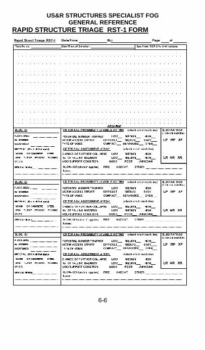
US&R STRUCTURES SPECIALIST FOG GENERAL REFERENCE
6-6
RAPID STRUCTURE TRIAGE RST-1 FORM

US&R STRUCTURES SPECIALIST FOG GENERAL REFERENCE
6-7
6
SAMPLE STRUCTURAL CALCULATIONS of EMERGENCY SHORING
MATERIAL PROPERTIES USED IN CALCULATIONS
Concrete Properties
Weight = 150 pcf Fc′ = 3000 psi (28-Day Strength)
Wood Allow Stress Design Properties – D. Fir & So. Pine One may increase these values by 25% for US&R Shores See Section 5 (FAQ) for Strength of other Wood Species
Mod. of Elasticity = E = 1,400 to 1,600 ksi
Bending Stress = Fb = 1500 psi for 4x and 1200 psi for 6x
(Sect. Modulus = S = BD2/6, Mom. of Inertia = I = BD3/12)
Horiz. Shear Stress = Fv = 95 psi for 4x and 85 psi for 6x (Fv has been increased by about 100% in the 2001 NDS) Compression Parallel to Grain = Fc = 1100 psi
Compression Perpendicular to Grain = Fc = 625 psi
Buckling Strength = Fa = 480,000 psi / (L/D)2
L/D = 25 max. (to see crushed cross-grain before buckling)
L/D = 50 max. (but failure may be by sudden buckling)
INDEX of SHORING CALCULATIONS
I-880 Vertical shoring of typical bent at the 2-story highway bridge (1989 Loma Prieta Quake) using 12x12 posts.
Pun-1 Vertical shoring scheme to reduce possibility of punching shear failure in typical flat-slab floor w/drop panel at column. This example uses 6x6 posts.
4-Story Diagonal bracing used from curb to 2nd floor in Marina Dist. (1989 Loma Prieta Quake) to stabilize 4-story wood apartment bldg. Work was done by Trost House Movers.
Rak2 Sample calc of Solid Sole, Double Raker System.
Rak1 Sample calc using Flying (Friction) Raker. Illustrates that capacity is reduced due to bending stress in Raker.
Tieback Sample calc for use of Tied-back Strong-backs, to restrain un-collapsed but damaged URM multi-story wall.
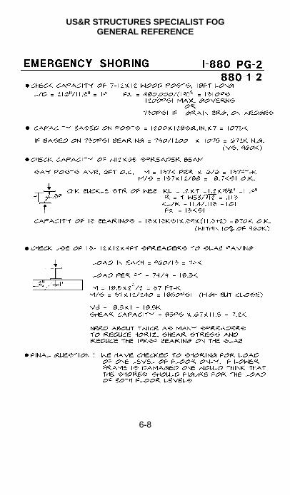
US&R STRUCTURES SPECIALIST FOG GENERAL REFERENCE
6-8

US&R STRUCTURES SPECIALIST FOG GENERAL REFERENCE
6-9
6

US&R STRUCTURES SPECIALIST FOG GENERAL REFERENCE
6-10

US&R STRUCTURES SPECIALIST FOG GENERAL REFERENCE
6-11
6
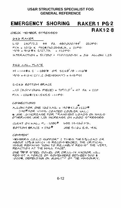
US&R STRUCTURES SPECIALIST FOG GENERAL REFERENCE
6-12

US&R STRUCTURES SPECIALIST FOG GENERAL REFERENCE
6-13
6

US&R STRUCTURES SPECIALIST FOG GENERAL REFERENCE
6-14

US&R STRUCTURES SPECIALIST FOG GENERAL REFERENCE
6-15
6
ICS BASE MAP SYMBOLOGY
Time denoted—22Aug03 0700hrs - (with arrow pointing to activity site)
Incident Command Post
Incident Base B
Camp C
Decon Area D
Fire Station F
Helibase H
Telephone T
Repeater/Mobile Relay R
Staging Area (by name)
Mobile Weather Station
First Aid Station
Drop Point
D-P
W
S
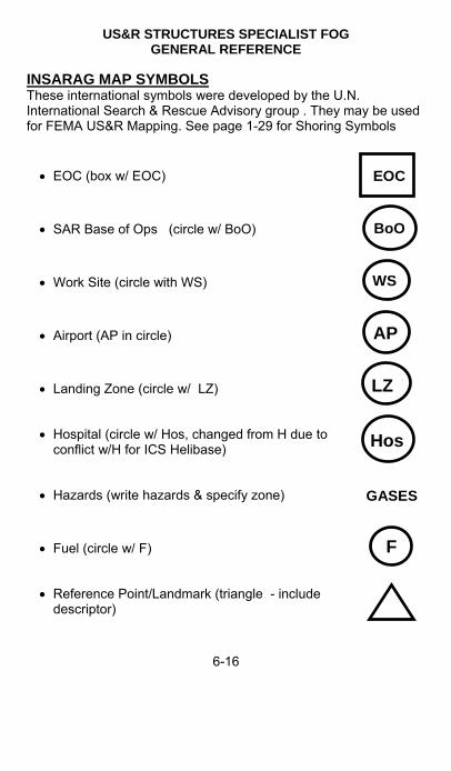
US&R STRUCTURES SPECIALIST FOG GENERAL REFERENCE
6-16
INSARAG MAP SYMBOLS These international symbols were developed by the U.N. International Search & Rescue Advisory group . They may be used for FEMA US&R Mapping. See page 1-29 for Shoring Symbols
EOC (box w/ EOC)
EOC
SAR Base of Ops (circle w/ BoO)
BoO
Work Site (circle with WS)
WS
Airport (AP in circle)
Landing Zone (circle w/ LZ)
Hospital (circle w/ Hos, changed from H due to conflict w/H for ICS Helibase)
Hazards (write hazards & specify zone) GASES
Fuel (circle w/ F)
Reference Point/Landmark (triangle - include descriptor)
F
Hos
LZ
AP

US&R STRUCTURES SPECIALIST FOG GENERAL REFERENCE
6-17
6
OTHER STANDARD DRAWING SYMBOLS These symbols should be used as needed for FEMA US&R Sketches, Maps and Drawings

US&R STRUCTURES SPECIALIST FOG GENERAL REFERENCE
6-18
OTHER STANDARD DRAWING SYMBOLS (continued)

US&R STRUCTURES SPECIALIST FOG GENERAL REFERENCE
6-19
6
CRITICAL INCIDENT STRESS - 1
CRITICAL INCIDENT STRESS (CIS) results from a crisis event, so overwhelming to the individual that it is likely to cause short or long term malfunctioning.
GENERAL:
1. The effects of CIS impair functioning on-scene and may continue to emerge upon demobilization or thereafter.
2. Self monitoring and management of CIS is critical for both short and long term personal well being and team performance.
3. As a Structures Specialist, you will be working in an environment that is difficult (at best) that may produce CIS reactions because of the following factors: a. Exposure to extreme stimulus involving death, mutilation, destruction, and threat under arduous conditions. b. Pressure to make consequential decisions under aggravated conditions of uncertainty, fatigue, and duress. c. Role conflict, competing demands, shifting command and assignments, and an changing scope of work.
ALERT:
1. If after self examination you feel unready to proceed with the assignment, do not accept it. It is better to remain fit for future assignments than to become impaired from this.
2. Following factors can create special vulnerability to CIS: Prior Trauma Background Stress Family Disruption/Discord Physical Fatigue Psychological Need Recent Changes/Loss Feelings of Inadequacy Overly Optimistic or Pessimistic Beliefs

US&R STRUCTURES SPECIALIST FOG GENERAL REFERENCE
6-20
CRITICAL INCIDENT STRESS - 2 RECOGNITION: On-scene CIS is termed ACUTE STRESS RESPONSE (ASR). ASR at the disaster scene can manifest itself in altered thought process, emotions, physical symptoms, and behavior. ASR may manifest in yourself or others. The signs of ASR can include various combinations of the symptoms listed below:
COGNITIVE: Confusion Memory Loss Can't Recall Words Time Distortion Difficulties with Problem Solving Trouble Prioritizing
EMOTIONAL: Fear Anger Frustration Anguish Numb Anxiety Intense Frustration "Inappropriate" Feelings "Overwhelmed"
PHYSICAL: Headaches Heart Palpitations Muffled Hearing Nausea Cramps Profuse Sweating Rapid Breathing Fainting Other Signs of Shock

US&R STRUCTURES SPECIALIST FOG GENERAL REFERENCE
6-21
6
CRITICAL INCIDENT STRESS - 3 ASR normally consists of some combination of these symptoms into one of two general categories: AGITATED or DEPRESSED. Look for the following:
AGITATED ( 25% of ASR Cases):
Appearance: Flushed, sweating, agitated
Mood: Panicked, enraged, hysterical
Behavior: Rapid, frenzied, ineffectual, uncontrolled
DEPRESSED (75% of ASR Cases):
Appearance: Pale, submissive, shock-like
Mood: Blunted, numb, emotionally unresponsive
Behavior: Slowed, automatic, paralyzed, immobilized SELF MANAGEMENT:
Remember and resist your tendency to ignore your own needs. If you are not functioning fully, you will be a danger to others on- scene, to yourself, and later on to your family.
If you are experiencing some of the signs of ASR:
Let your partner and supervisor know about it.
Act on your own behalf:
Take an extended break away from the disaster scene.
Take fluids and nourishment (cut down caffeine and sugar - increase carbohydrates).
Discuss your experiences and reactions with others.
Listen to the advice of trusted others.
Do not resume duties until you are reoriented and re-stabilized.
Ask for and accept support services, such as on-scene consultation or debriefing ASAP.

US&R STRUCTURES SPECIALIST FOG GENERAL REFERENCE
6-22
CRITICAL INCIDENT STRESS - 4
MANAGEMENT OF OTHERS:
If you observe others (partners, colleagues, or supervisors) exhibiting ASR signs: Convey your observations and concerns to that person. Advise that person to follow the general protocols for self- management.
If person is AGITATED: Use firm, calm directions to gain attention and provide direction. When providing feedback regarding your concerns, focus on behavior rather than the person. Provide simple but relevant and useful tasks. Get medical assistance.
If person is DEPRESSED: Have individual sit or lie down. Be supportive and check for comprehension. Do not overload with information or negative content. Screen for shock. Get medical assistance.
ON-SCENE CIS SERVICES:
CIS services may be available through the Task Force or Unit to which you are assigned.
Initially you should request CIS services through the Task Force
lf CIS services are unavailable through your unit of assignment, they can be obtained through the IST Overhead personnel.
The Corps US&R Field Coordinators are authorized to arrange CIS services for Corps US&R personnel. These services may be available to US&R Task Force personnel.
CIS debriefings are normally provided at the demobilization site prior to your return home as part of the standard out-processing procedures, and will be coordinated through overhead personnel.

US&R STRUCTURES SPECIALIST FOG GENERAL REFERENCE
6-23
6
CRITICAL INCIDENT STRESS - 5 HOME STATION (POST DEPLOYMENT): Delayed stress reactions are possible in the days, weeks, or months following your return from the disaster. SELF-MONITORING: Self-monitoring is just as important after returning home as it is during US8 R operations. You should monitor yourself for any of the following reactions: Flashbacks Nightmares Problems at Home Problems at Work Depression Anxiety Guilt Fears Isolation Difficulty Relating to Others Problems with Self-Control Disproportionate Emotionality Obsessive Thoughts About Incident Psychosomatic Illness Precipitous Life Changes Unhappiness/Dissatisfaction These reactions, if moderate, are fairly normal and transient. If they last more than four to six months, however, or are negatively effecting your personal or work life, you should get help in working through those thoughts, feelings or attitudes engendered by the disaster experience.

US&R STRUCTURES SPECIALIST FOG GENERAL REFERENCE
6-24
CRITICAL INCIDENT STRESS - 6 FOLLOW-UP: It is suggested that you make 3 visits with your home station CIS provider after returning home. The schedule of suggested visits is as follows: (R = return date): R + 3-5 Days R + 2 Weeks R + 2 Months Take full advantage of these opportunities to discuss your feelings and reactions. These can include reactions encountered privately, within your family, and at work. Any of the reactions listed earlier should be included in the discussion(s). CIS guidelines have been furnished to your local CIS provider. In addition, they have been given material to assist your family and supervisors. If your CIS provider or your family suggest meeting together, take the request seriously, even if you do not see the need yourself. They may see something that you don't. They are worth the effort. The last people you want to hurt are your family members and loved ones. You can hurt them by your left over fears and anger. You can also hurt them by withdrawing into yourself and shutting them out. Talk to them about your experiences (children can be spared the graphic details).

US&R STRUCTURES SPECIALIST FOG GENERAL REFERENCE
6-25
6
HAZMAT FIRST RESPONDER AWARENESS Structures Specialists should carry their Department of Transportation's Emergency Response Guidebook (DOT P 5800.5) during deployment. As a Structures Specialist conducting an initial evaluation of an incident, you may be the first to encounter or discover a HAZMAT condition. When surveying the incident, be aware of potential HAZMAT indicators: Unusual colors/odors
People running from scene
Evidence of Leak
Unusual noise in fittings/valves
Container Shapes
Placards or Signs
Occupancy/Location
Upon discovery or suspicion of a HAZMAT situation your mission is as follows: SAFETY of yourself and team members. ISOLATE & DENY ENTRY. NOTIFICATION of Team HAZMAT specialist or local authorities.
THINK SAFETY AT ALL TIMES.

US&R STRUCTURES SPECIALIST FOG GENERAL REFERENCE
6-26
ROPES, KNOTS & HARNESSES - 1

US&R STRUCTURES SPECIALIST FOG GENERAL REFERENCE
6-27
6
ROPES, KNOTS & HARNESSES - 2

US&R STRUCTURES SPECIALIST FOG GENERAL REFERENCE
6-28
ROPES, KNOTS & HARNESSES - 3

US&R STRUCTURES SPECIALIST FOG GENERAL REFERENCE
6-29
6
ROPES, KNOTS & HARNESSES - 4
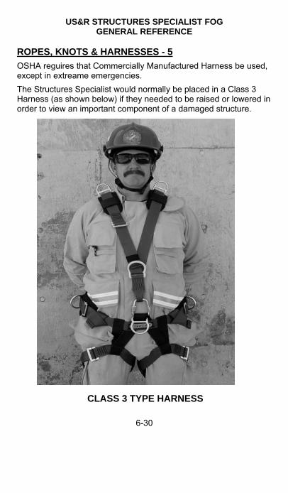
US&R STRUCTURES SPECIALIST FOG GENERAL REFERENCE
6-30
ROPES, KNOTS & HARNESSES - 5
OSHA reguires that Commercially Manufactured Harness be used, except in extreame emergencies.
The Structures Specialist would normally be placed in a Class 3 Harness (as shown below) if they needed to be raised or lowered in order to view an important component of a damaged structure.
CLASS 3 TYPE HARNESS

US&R STRUCTURES SPECIALIST FOG GENERAL REFERENCE
6-31
6
DESIGN LOAD OF PICKETS (PINS) IN SOILS
The following pickets have been tested during StS2 Training since 2004. These tests were performed in relativly firm cohesive soil. 40 - 1" dia x 48" plain bar driven 36" to 42" into ground 8 - 1" dia x 48" rebar driven 36" into ground 8 - 1" dia x 36" rebar driven 24" to 30" into ground 13 - 5/8 x 36" screed pins driven 24" to 30" into ground
Based on these tests the Recommended Design Lateral Load Capacity for these Pickets in Firm Cohesive Soils is as follows:
1. 750 lb for 1"dia x 36"(min) plain bar or rebar driven 24"(min) into ground.
2. 375 lb for 5/8 x 36" screed pins driven 24" (min) into ground.
The table below is based on July 1984, FHWA-IP-84-11, Handbook, Design of Piles & Drilled Shafts Under Lateral Load. Pin Design Load is based on approx 50% of Capacity Design Lateral Load Capacity of Pin in Cohesive Soil 1" dia, 42 to 48-inch pin, driven 36 inches into soil Soil Type Soil Capacity, lb/sq ft Pin Design Load Poor 1400 500 Average 2200 750 Good/Hard 3200 1000 Design Lateral Load Capacity in Cohesionless Soil 1-inch dia, 48-inch pin, driven 36 inches into soil Soil Type Soil density, lb/sq ft Pin Design Load Loose 100 50 Medium 115 55 Dense 125 63 Design Lateral Load Capacity of Pin in Cohesive Soil 5/8-inch dia, 36-inch Screed Pin, driven 30 inches into soil Soil Type Soil Capacity, lb/sq ft Pin Design Load Poor 1400 250 Average 2200 375

US&R STRUCTURES SPECIALIST FOG GENERAL REFERENCE
6-32
ROPE ANCHORS USING PICKETS
Multi picket layouts should provide capacity that is greater than a single picket. However, the capacity of a pair or more will be less than that of a single picket times the total number of pickets.
Starting in 2010, pairs of pickets were tested during StS2 Training. The tests were performed as follows:
1" diameter x 36" and 48" steel pickets were spaced about 3 feet on center, and embeded a minimum of 30" into the ground. The bars were both smooth bar and rebar.
Pairs of pickets were driven at angles of zero and 20 degrees off the vertical, and about 12" was left exposed above ground.
A double wrap of 1" nylon webbing was placed from top of the front picket to the ground level of the rear picket.
The test load was applied at the ground level of the front picket, and a total of 12 pairs were tested to failure.
Based on these tests: Design Load of 1200lbs is recommended for a pair of 1" diameter steel pickets driven 30" min. into firm cohesive soil, spaced 3 feet apart, and tied tigether with a double wrap of 1" nylon webbing.

US&R STRUCTURES SPECIALIST FOG GENERAL REFERENCE
6-33
6
US&R STRUCTURES SPECIALIST FOG GENERAL REFERENCE
6-34
CRANE HAND and VOICE SIGNALS (By National Commission for the Certification of Crane Operators) The NCCCO standard Hand Signals are the same as shown on the previous page.
Crane Voice Signals The NCCCO Voice Signals must contain the following 3 elements.
Function and direction.
Distance and/or speed.
Function stop.
Acceptable voice signal functions are:
Hoist, or Raise the load : Lower.
Raise/Lower boom, or Boom up/down.
Extend/Retract boom, or Telescope out/in.
Raise boom and lower the load, or Boom up and lower the load.
Lower boom and raise the load, or Boom down and raise/hoist the load.
Swing right, Swing left.
Use main hoist, use whip line / auxiliary hoist.
Stop
Voice Crane Signal Examples:
Swing right 50ft, 25ft, 10ft, 5ft, 2ft, swing stop
Lower load 100ft, 50ft, 25ft, 10ft, 5ft, 2ft, lower stop.
Hoist load slow, slow, keep hoisting slow, hoist stop
Voice signals are normally transmitted by hand-held radio or telephone, and must be clear and loud in order to be heard over the noise of the machinery.
The radio or telephone devices and communication must be checked prior to any lifting, to ensure that instructions can be clearly understood with normal operational noise.

US&R STRUCTURES SPECIALIST FOG GENERAL REFERENCE
6-35
6
EXCAVATOR HAND SIGNALS - 1

US&R STRUCTURES SPECIALIST FOG GENERAL REFERENCE
6-36
EXCAVATOR HAND SIGNALS - 2
US&R STRUCTURES SPECIALIST FOG USEFUL TABLES
7-1
7
INTRODUCTION to SECTION 7
This section contains Information and Engineering Tables that may become useful during US&R Operations.
The following sets of Tables are contained in this section: Table Page Wind Pressure Table 7-2 Timber Design Guide 7-3 Plywood for Uniformly Loaded Floors 7-5 Plywood Floors Supporting Fork-Lift Truck Traffic 7-6 Bolts in Wood (Double Shear) 7-7 Bolts in Wood (Single Shear) 7-9 Lag Screws Single Shear Values 7-11 Working Load Values - Wire Nails 7-12 Lag Screw Withdrawal Values 7-12 Steel Design Guide 7-13 Structural Steel Allowable Stress – Compression 7-14 Structural Steel Tubing Dimensions and Properties 7-15 Structural Steel Pipe Dimensions and Properties 7-16 Allowable Steel Bolt Loads – Shear and Tension 7-17 Concrete Design Guide & Area/Weight of A615 Rebar 7-18 Rigging - Working Load Limit/design Load 7-22 Crane Stability – Percent of Tipping & Safety Factors 7-22 Wire Rope Slings Capacities 7-24 Sling Information 7-25 Wire Rope Discard Conditions 7-26 Wire Rope Inspection and Replacement 7-27 Synthetic Sling Information 7-30 Wedge Anchor Allowable Loads – Tension and Shear 7-32 Anchors – Epoxy & Acrylic Adhesives 7-34 Airshore Struts and Rakers – Design Capacity 7-35 Paratech Struts and Rakers 7-37

US&R STRUCTURES SPECIALIST FOG USEFUL TABLES
7-2
WIND PRESSURES ON BUILDINGS, PSF
Notes: 1. Ref. wind speed measured at height of 30 feet above grade. 2. Basic stagnation pressure, P = 0.00256V 2, where V is in mph & P is in psf. (10psf recommended for design in most situations, but may use 5psf if anticipated conditions warrant) 3. Pressure coeff. based on exposure B for urban environment. 4. Pressures include gust factor & shape coefficient of 1.3. 5. Pressure acting on net area normal to wind. 6. For open frame towers built with members angular cross-section multiply table values by 3 and apply to total normal projected area of all elements on one face . 7. For open frame towers built with members of circular cross-section multiply table values by 2 and apply to total normal projected area of all elements on one face. 8. Reference 1997 UBC Chapter 16, Division III and ASCE 7
Height Wind Speed in Miles per Hour Feet 10 20 30 40 50 60 70 80 90 100
15 5.0 5.0 5.0 5.0 5.2 7.4 10 13 17 21 20 5.0 5.0 5.0 5.0 5.6 8.0 11 14 18 22 25 5.0 5.0 5.0 5.0 6.0 8.6 12 15 19 24 30 5.0 5.0 5.0 5.0 6.3 9.1 12 16 20 25 40 5.0 5.0 5.0 5.0 7.0 10 14 18 23 28 60 5.0 5.0 5.0 5.1 7.9 11 15 20 26 32 80 5.0 5.0 5.0 5.5 8.7 12 17 22 28 35 100 5.0 5.0 5.0 6.0 9.4 13 18 24 30 38 120 5.0 5.0 5.0 6.4 10 14 20 26 32 40 160 5.0 5.0 5.0 7.0 11 16 21 28 35 44 200 5.0 5.0 5.0 7.6 12 17 23 30 38 47 300 5.0 5.0 5.0 8.7 14 20 27 35 44 54 400 5.0 5.0 5.4 9.6 15 22 29 38 49 60

US&R STRUCTURES SPECIALIST FOG USEFUL TABLES
7-3
7
INTRODUCTION TO USEFUL TABLES - TIMBER DESIGN
Following this page there are tables that provide:
Allowable Loads for Plywood
Allowable Loads in Bolts and Lag Screws
Allowable Loads in Nails & Screws
This information is provided for Southern Pine, Douglas Fir, Hem-Fir Group and Spruce-Pine-Fir Species.
The Tables have been reproduced from “National Design Specifications for Wood Construction, 1991 Edition”. WORKING LOAD STRESSES – DOUG. FIR & SO. PINE One may increase these values by 25% for US&R Shores (On page 7-12, note that a 60% increase is recommended when using nails that resist transient loading – Raker Shores)
Mod. of Elasticity = E = 1,400 to 1,600 ksi
Bending Stress = Fb = 1500 psi for 4x & 1200 psi for 6x (Sect. Modulus = S = BD2/6, Mom. of Inertia = I = BD3/12)
Horiz. Shear Stress = Fv = 95 psi for 4x & 85 psi for 6x (Fv has been increased by about 100% in the 2001 NDS)
Compression Parallel to Grain = Fc = 1100 psi
Compression Perpendicular to Grain = Fc = 625 psi
Buckling Strength = Fa = 480,000 psi / (L/D)2
L/D = 25 max. (to see crushed cross-grain before buckling)
L/D = 50 max. (but failure may be by sudden buckling)
Note that Working Load Stresses for Hem-Fir Group are 15% less, and Spruce-Pine-Fir Species are 25% less than those listed above

US&R STRUCTURES SPECIALIST FOG USEFUL TABLES
7-4
DESIGN DEAD LOADS for COMMON MATERIALS (Repeated from page 1- 30)
Normal Reinforced Concrete = 150 pcf (12” conc slab weighs 150 psf , 6” slab weighs 75psf, etc)
Heavily Reinf. Conc Beams & Cols = 160 to 180 pcf
Struct. Steel = 490 pcf = 40 psf for 1” thick steel plate
Aluminum = 165 pcf = 14 psf for 1” thick aluminum plate
Masonry and Cement Plaster = 125 pcf
Dry Wood = 35 pcf Wet Wood = 45 to 60 pcf
Wood Joist@16″ o.c. = 3 psf 3/4″ Wood Flooring = 2.5 psf 5/8″ Gypsum Board = 2.5 psf Frame wall with1/2″ Gyp ea. Side = 7 psf Frame wall with 5/8″ Gyp ea. Side = 8 psf 8″ PC Hollow Plank = 60 psf 8″ Hollow Conc Masonry = 40 psf Concrete Masonry Rubble = 10 psf per inch of thickness Interior wood & metal stud walls = 10 to 15 psf per floor Normal home or office furniture = 10 psf (more for storage) Wood Floors weigh 10 psf to 25 psf (25 with 1.5″ conc fill)
Steel Floors with metal deck & conc fill weigh 50 to 70 psf
Concrete Floors weigh from 80 to 150 psf
RESCUE LIVE LOADS Add 10 to 15 psf for Rescuers (4-250lb in 100 sq ft = 10 psf) (Also need to account for heavy tools)

US&R STRUCTURES SPECIALIST FOG USEFUL TABLES
7-5
7
Allowable Uniformly Loaded Plywood Floors (APA Rated and Sturd-I-Floor)
Span Rating (Nom. Inch Thickness)
Spacing of Supports, in.
12 16 24
24/16 (.437) 267 150 67
32/16 (.469) 308 173 77
16oc (.594) 346 195 86
20oc (.594) 400 225 100
40/20 (.594) 521 293 130
24oc (.719) 533 300 133
48/24 (.719) 704 396 176
32oc (.875) 725 408 181
48oc (1.125) 1333 750 333
Notes: 1. Table from APA Nov 2001. Normal load duration, dry conditions, 2” nom. wide supports (min.). Bending governs. Duration factors may be used. 2. For APA Rated Sheathing: 24/16 style rating, 24 = roof rating with L/180 deflection and 16 = floor rating with L/360 deflection. For Sturd-I-Floor: 16oc style rating, floor span rated with L/360 deflection. 3. Order “Rated” panels by “Span Rating” (stamped on the plywood) not thickness. Can be plywood or OSB. 4. Face grain perpend. to span. Block all edges, unless T&G or separate wearing surface. Reduce bending strength by up to a factor of 5 for face grain parallel.

US&R STRUCTURES SPECIALIST FOG USEFUL TABLES
7-6
Plywood Floors Supporting Fork-Lift Truck Traffic (taken from APA Pub. Plywood Floors for Lift Truck Traffic) Maximum Recommended 2” x 7” Concen. Load (for rolling cyclic loads) – Pounds (12” Spans, 2-5/8” (min) Wide Supports)
2 Layers 5/8” Struct 1, C-D – joints staggered 2 ft, unglued
1600
2 Layers 3/4” Group 1, A-C– joints staggered 2 ft, unglued
2300
2 Layers 7/8” Struct 1, A-A, glued 4550 2 Layers 1-1/8” Struc 1, A-A, glued 5850 Single Layer 1” Struc 1, A-A 1600 Single Layer 1-1/8” Struc 1, A-A 2300 Notes: 1. Values given are 65% of the tested first distress. 2. Wheel loads used on here were 2” long by the width of the tire. 3. Only solid rubber or pneumatic tires should to be used on
plywood floors (No Steel Wheels). 4. Plywood supporting softer tires with a larger tire bearing area
will have a significant increase in performance. 5. All plywood joints should occur over framing members. Nail all
plywood to supports at 6” o.c. maximum. 6. Two layers of plywood glued together provides only slightly
better performance than unglued panels for vehicle loads due to the rolling shear failure mode.
7. Factory laminated panels of a single thickness perform better that multiple layers panels (less significant at thicker panels).
8. Plywood can support only 70% of the weight with 4” wide tires versus the weight it can carry for 8” wide tires. The reduction is linear with the tire width.
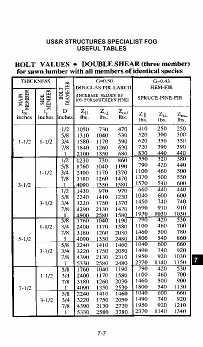
US&R STRUCTURES SPECIALIST FOG USEFUL TABLES
7-7
7

US&R STRUCTURES SPECIALIST FOG USEFUL TABLES
7-8

US&R STRUCTURES SPECIALIST FOG USEFUL TABLES
7-9
7

US&R STRUCTURES SPECIALIST FOG USEFUL TABLES
7-10

US&R STRUCTURES SPECIALIST FOG USEFUL TABLES
7-11
7

US&R STRUCTURES SPECIALIST FOG USEFUL TABLES
7-12
WORKING LOAD VALUES for WOOD CONNECTORS WIRE NAILS Doug. Fir & So. Pine (see 7-3, other spices reduction) (Values include 60% increase for emergency shoring 1.) Nail Size
Nail Length
Nail Diameter
Shear Value (in pounds)
8d 2 ½″ 0.131 140 10d 3″ 0.148 190 16d Cooler
3 ¼″ 0.148 190 Vinyl coated
16d 3 ½″ 0.162 225 Min. Penetration & Spacing is ½ of the Nail Length
1. The 60% increase is justified for the Raker Cleat nailing, due to the transient nature of their maximum loading.
2. Nailing is not used to transfer direct loads in any other type of emergency shoring.
LAG SCREW WITHDRAWAL VALUES In pounds per inch of threaded penetration Shank Diameter Inches
Southern Pine
Douglas Fir Hem-Fir & Spruce-Pine-Fir
1/4 260 225 175 5/16 307 266 210 3/8 352 305 240 7/16 395 342 270 1/2 437 378 295 5/8 516 447 350 3/4 592 513 400 7/8 664 576 450 1 734 636 500
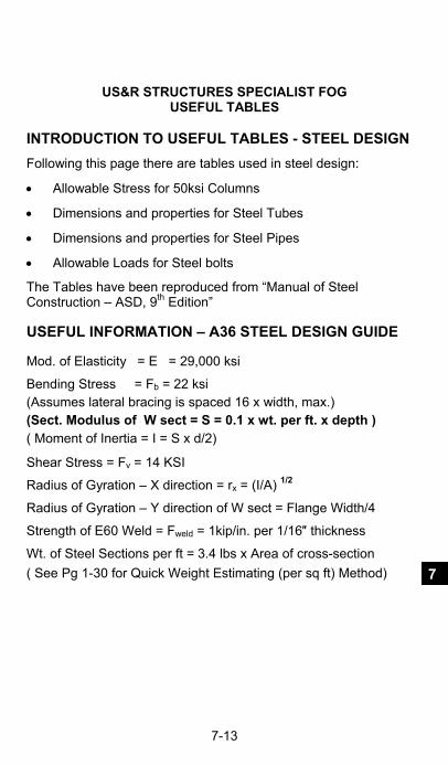
US&R STRUCTURES SPECIALIST FOG USEFUL TABLES
7-13
7
INTRODUCTION TO USEFUL TABLES - STEEL DESIGN
Following this page there are tables used in steel design:
Allowable Stress for 50ksi Columns
Dimensions and properties for Steel Tubes
Dimensions and properties for Steel Pipes
Allowable Loads for Steel bolts
The Tables have been reproduced from “Manual of Steel Construction – ASD, 9th Edition” USEFUL INFORMATION – A36 STEEL DESIGN GUIDE Mod. of Elasticity = E = 29,000 ksi
Bending Stress = Fb = 22 ksi (Assumes lateral bracing is spaced 16 x width, max.) (Sect. Modulus of W sect = S = 0.1 x wt. per ft. x depth ) ( Moment of Inertia = I = S x d/2)
Shear Stress = Fv = 14 KSI
Radius of Gyration – X direction = rx = (I/A) 1/2
Radius of Gyration – Y direction of W sect = Flange Width/4
Strength of E60 Weld = Fweld = 1kip/in. per 1/16″ thickness
Wt. of Steel Sections per ft = 3.4 lbs x Area of cross-section
( See Pg 1-30 for Quick Weight Estimating (per sq ft) Method)

US&R STRUCTURES SPECIALIST FOG USEFUL TABLES
7-14

US&R STRUCTURES SPECIALIST FOG USEFUL TABLES
7-15
7

US&R STRUCTURES SPECIALIST FOG USEFUL TABLES
7-16

US&R STRUCTURES SPECIALIST FOG USEFUL TABLES
7-17
7

US&R STRUCTURES SPECIALIST FOG USEFUL TABLES
7-18
USEFUL INFORMATION – CONCRETE DESIGN GUIDE
The following information is intended as a Quick Field Design Guide for Reinforced Concrete. It is not intended to replace the more rigorous analysis that is required for “Normal” Engineering Calculations.
Approx. Moment Capacity of Reinforced Slabs or Beams:
M (ft-k) = 2.8 x As x d (for 40 ksi yield strength).
M (ft-k) = 4.0 x As x d (for 60 ksi yield strength).
Where: M = Moment Capacity in ft-kips.
As = Area of reinforcing steel (sq. in.) listed below.
d = depth from compression face to center of steel. Notes: 1. If in doubt, assume 40ksi yield strength for rebar. 2. The above assumes that the area of rebar is 1% or less, of the
concrete cross-section (b x d). 3. Shear capacity may govern any reinforced concrete design.
AREA & WEIGHT of A615 REINFORCING STEEL
Size 3 4 5 6 7 8 9 10 11
Area 0.11 0.20 0.31 0.44 0.60 0.79 1.0 1.27 1.56
Wt/Ft 0.38 0.67 1.1 1.5 2.0 2.7 3.4 4.3 5.3
Metric Size
10 13 16 19 22 25 29 32 36

US&R STRUCTURES SPECIALIST FOG USEFUL TABLES
7-19
7
INTRO TO USEFUL TABLES – CRANE & RIGGING Following this page there are tables that provide information that needs to be considered when ordering a Crane, information on the following: Crane Stability Safety Factors Wire Rope Slings Wire Rope Inspection Terminations Synthetic Slings Hoist Rings Wedge Anchors Concrete Screws This Information has been reproduced from various sources, including: The Crosby Group Inc, P.O. Box 3128 Tulsa, OK 1-800-777-1555 www.thecrosbygroup.com The very useful Crosby User’s Pocket Guide is highly recommended as a reference to be used during all Urban Search & Rescue Activities. It may be obtained directly from The Crosby Group.
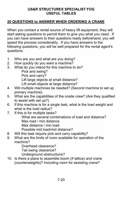
US&R STRUCTURES SPECIALIST FOG USEFUL TABLES
7-20
20 QUESTIONS to ANSWER WHEN ORDERING A CRANE When you contact a rental source of heavy lift equipment, they will start asking questions to permit them to give you what you need. If you can have answers to their questions ready beforehand, you will speed the process considerably. If you have answers to the following questions, you will be well prepared for the rental agent's questions. 1. Who are you and what are you doing? 2. How quickly do you want a machine? 3. What do you intend for this machine to do? Pick and swing? Pick and carry? Lift large objects at small distance? Lift small objects at large distance? 4. Will multiple machines be needed? (Second machine to set up primary machine). 5. What are the capabilities of the onsite crew? (Are they qualified to assist with set up?) 6. If this machine is for a single task, what is the load weight and what is the load radius? 7. If this is for multiple tasks? What are several combinations of load and distance? Max load / min distance Max distance / min load Possible mid load/mid distance? 8. Will this task require pick and carry capability? 9. What are the limits of room available for operation of the machine? Overhead clearance? Tail swing clearance? Underground obstructions? 10. Is there a place to assemble boom (if lattice) and crane (counterweights)? Including room for assisting crane?
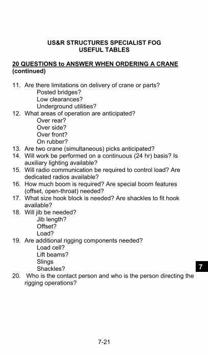
US&R STRUCTURES SPECIALIST FOG USEFUL TABLES
7-21
7
20 QUESTIONS to ANSWER WHEN ORDERING A CRANE (continued) 11. Are there limitations on delivery of crane or parts? Posted bridges? Low clearances? Underground utilities? 12. What areas of operation are anticipated? Over rear? Over side? Over front? On rubber? 13. Are two crane (simultaneous) picks anticipated? 14. Will work be performed on a continuous (24 hr) basis? Is auxiliary lighting available? 15. Will radio communication be required to control load? Are dedicated radios available? 16. How much boom is required? Are special boom features (offset, open-throat) needed? 17. What size hook block is needed? Are shackles to fit hook available? 18. Will jib be needed? Jib length? Offset? Load? 19. Are additional rigging components needed? Load cell? Lift beams? Slings Shackles? 20. Who is the contact person and who is the person directing the rigging operations?

US&R STRUCTURES SPECIALIST FOG USEFUL TABLES
7-22
RIGGING - WORKING LOAD LIMIT/DESIGN LOAD Given in terms of Diameter 2
ITEM Safe Working Load in Tons
Wire Rope (S.F.=5 ) D 2 x 9 Tons
Wire Rope Slings D 2 x 8.5 Tons
Shackles (Alloy) D 2 x 12.5 Ton
Shackles (carbon) D 2 x 8.5 Tons
Chain Slings ( I. D. as Type A)
D 2 x 24 Tons
Turnbuckles D 2 x 5 Tons
(Improved Plow, IWRC Wire Rope) CRANE STABILITY Percent of Tipping & Safety Factor (for leveled crane)
Crane Type
% of Tipping
S.F.
Locomotive 85% 1.18
Crawlers 75 1.33 Mobile (on O. Riggers)
85 1.18
Mobile (on Tires) 75 1.33
Boom Truck 85 1.18

US&R STRUCTURES SPECIALIST FOG USEFUL TABLES
7-23
7
GENERAL SLING INFORMATION Center of Gravity The center of gravity of an object is that point at which the entire weight may be considered as concentrated. In order to make a level lift, the crane hook must be directly above this point. While slight variations are usually permissible, if the crane hook is too far to one side of the center of gravity, dangerous tilting and/or swinging will result and should be corrected at once. For this reason, when the center of gravity is closer to one point of the sling attachment than to the other, the slings must be of unequal length. The sling stresses and sling angle will also be unequal. Working Load Limit or Design Load The working load limit or design load is the useful rated capacity of a sling. This varies, depending upon the type of hitch. The working load limit table indicates, by illustration the applications for which the various useful loads apply, when the slings are new. All ratings are in tons or 2,000 pounds. Safety Factor In general, a safety factor of approximately five is maintained throughout these tables. However, certain sling fittings, such as hooks, which will straighten without breaking, or links, which will deform beyond usefulness before breaking, cannot be assigned a definite numerical safety factor. In such cases, suitable safe loads are listed, based upon wide experience and sound engineering practice. Sling Care Proper care and usage are essential for maximum service and safety. Wire rope and especially synthetic slings should be protected from sharp bends and cutting edges by means of corner saddles, burlap padding, or wood blocking. Heavy or continuous over-loading should be avoided as well as sudden jerks, which can build up a momentary over-load sufficient to break the sling. Wire rope slings should be stored where they are protected from moisture, and properly coiled when not in use.

US&R STRUCTURES SPECIALIST FOG USEFUL TABLES
7-24
WIRE ROPE SLINGS CAPACITIES – FLEMISH EYE
Working Capacity in Lbs (S.F. = 5) – 6 x 19 Improved Plow
Rope Dia. Inch 1/4 1120 800 2200 1940 1500 1120
5/16 1740 1280 3400 3000 2400 1740
3/8 2400 1840 4800 4200 3400 2400
7/16 3400 2400 6800 5800 4800 3400
1/2 4400 3200 8800 7600 6200 4400
9/16 5600 4000 11200 9600 7900 5600
5/8 6800 5000 13600 11800 9600 6800
3/4 9800 7200 19600 16900 13800 9800
7/8 13200 9600 26400 22800 18600 13200
1 17000 12600 34000 30000 24000 17000
1 1/8 20000 15800 40000 34600 28300 20000
1/1/4 26000 19400 52000 45000 36700 26000
1 3/8 30000 24000 60000 52000 42400 30000
A Basket Hitch has Twice the Capacity of a Single Leg only If the D/d Ratio is 25/1 and the Legs are Vertical
In order for ANY of the above Sling Capacities to be correct the Size of any SHACKLE used Must be One Size GREATER or LARGER

US&R STRUCTURES SPECIALIST FOG USEFUL TABLES
7-25
7
SPECIAL SLING CAPACITY INFORMATION
Wire Rope, Chain & Synthetic Basket Slings
Choker Hitches – Reduction Due to Angle
Sling Angle
Capacity as Percent of Single Vertical Hitch
90 200% 60 170% 45 141% 30 100%

US&R STRUCTURES SPECIALIST FOG USEFUL TABLES
7-26

US&R STRUCTURES SPECIALIST FOG USEFUL TABLES
7-27
7

US&R STRUCTURES SPECIALIST FOG USEFUL TABLES
7-28
WIRE ROPE SOCKET TERMINATIONS Swaged & Spelter Sockets are used on standing ropes
and permanent ropes like pendants. Wedge Sockets are used to attach Crane Whip Line to
the Headache Ball, etc. Do not attach dead end to live with wire rope clip.
O.K. NO Swaged Socket Spelter Socket Wedge Socket (100%) (100%) (75 to 90%) WIRE ROPE LOOP TERMINATIONS Without thimble, eye efficiency may be reduced as
much as 10%. Wire Rope Clips must be properly installed.
Flemish Eye Fold Back Wire Rope Clips Eye Eye U bolt & Fist Grip (95-100%) (Don’t use for lifting) (80%)
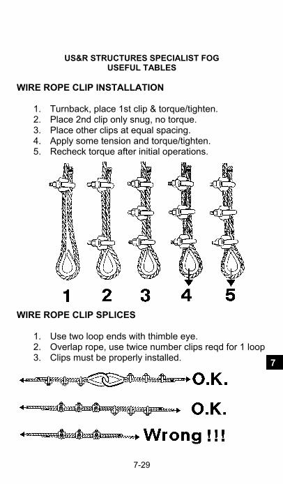
US&R STRUCTURES SPECIALIST FOG USEFUL TABLES
7-29
7
WIRE ROPE CLIP INSTALLATION
1. Turnback, place 1st clip & torque/tighten. 2. Place 2nd clip only snug, no torque. 3. Place other clips at equal spacing. 4. Apply some tension and torque/tighten. 5. Recheck torque after initial operations.
WIRE ROPE CLIP SPLICES
1. Use two loop ends with thimble eye. 2. Overlap rope, use twice number clips reqd for 1 loop 3. Clips must be properly installed.

US&R STRUCTURES SPECIALIST FOG USEFUL TABLES
7-30
SYNTHETIC SLING INFORMATION
Must include manufacturer’s sewn on Tag - Gives Fiber Type & Safe Working Load Provided with seamless protective cover Use corner protection Need careful Inspection Slings stretch as much as 10%, Polyethylene 1%
Triangle Double Dbl Rev Endless Return Choker Triangle Eye Eye Loop Eye ENDLESS ROUND SLING CAPACITY Working Capacity (Working Load Limit), in pounds
COLOR Wt #/ft Vertical Choker Basket
Purple 0.2 2,650 lb 2,120 5,300
Black 0.25 4,000 3,200 8,000
Green 0.3 5,300 4,240 10,600
Yellow 0.4 8,400 6,720 16,800
Tan 0.55 10,600 8,500 21,200 Red 0.6 13,200 10,560 26,400
White 0.9 16,800 13,400 33,600
Blue 1.0 21,200 17,000 42,400
Grey 2.15 31,000 24,800 62,000

US&R STRUCTURES SPECIALIST FOG USEFUL TABLES
7-31
7

US&R STRUCTURES SPECIALIST FOG USEFUL TABLES
7-32
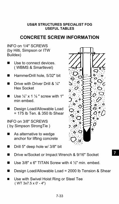
US&R STRUCTURES SPECIALIST FOG USEFUL TABLES
7-33
7
CONCRETE SCREW INFORMATION INFO on 1/4″ SCREWS (by Hilti, Simpson or ITW Buildex) Use to connect devices. ( WBMS & Smartlevel) HammerDrill hole, 5/32″ bit Drive with Driver Drill & ¼″
Hex Socket Use ¼” x 1 ¼ ″ screw with 1″
min embed. Design Load/Allowable Load
= 175 lb Ten. & 350 lb Shear INFO on 3/8″ SCREWS ( by Simpson StrongTie ) As alternative to wedge
anchor for lifting concrete Drill 5″ deep hole w/ 3/8″ bit Drive w/Socket or Impact Wrench & 9/16″ Socket Use 3/8″ x 6″ TITAN Screw with 4 ½″ min. embed. Design Load/Allowable Load = 2000 lb Tension & Shear Use with Swivel Hoist Ring or Steel Tee ( WT 3x7.5 x 0' - 4″)

US&R STRUCTURES SPECIALIST FOG USEFUL TABLES
7-34
ANCHORS - EPOXY & ACRYLIC ADHESIVES Allowable Loads – Threaded Rod – 2000psi Conc Allowable Tensile Loads – (Lbs) Dimensions in inches Stud Dia. Inch
Drill Bit Dia
Min Embed Depth
Spa- cing
Edge Dist.
Ave Ult Lbs
Allow Load Lbs
3/8 1/2 3 1/2 6 5 8800 2100 1/2 5/8 4 1/4 7 1/2 6 15,700 3750 5/8 3/4 5 9 1/2 7 1/2 23,000 5720 3/4 7/8 6 3/4 12 10 35,600 8460 7/8 1 7 3/4 13 1/2 11 1/2 42,800 10,900 1" 1 1/8 9 15 3/4 13 1/2 50,500 13,800
Allowable Shear Loads (Lbs) Stud Dia. Inch
Drill Bit Dia
Min Embed Depth
Edge Dist.
Ave Ult Lbs
Allow Load Lbs
Allow A307 Steel
3/8 1/2 3 1/2 5 5500 1380 1085 1/2 5/8 4 1/4 6 10,000 2500 1930 5/8 3/4 5 7 1/2 15,600 3900 3025 3/4 7/8 6 3/4 10 20,300 5000 4360 7/8 1 7 3/4 11 1/2 30,800 7700 5925 1” 1 1/8 9 13 1/2 33,500 8400 7740
Allowable Loads – A615 Gr 60 Rebar – 2000psi Conc Allowable Tensile / Shear Loads – (Lbs) Dimen. in inches Bar Size No.
Drill Bit Dia
Min Embed Depth
Spa- cing
Edge Dist.
Allow Ten. Load
Allow Shear Load
#4 5/8 4 1/4 7 1/2 6 3185 2750 #5 3/4 5 10 7 1/2 5100 3940 #6 7/8 6 3/4 12 10 7960 5830 #8 1 1/8 9 15 1/2 13 1/2 12500 8360 Note: All construction adhesives have a useful (shelf) life of about one year

US&R STRUCTURES SPECIALIST FOG USEFUL TABLES
7-35
7
HURST- AIRSHORE RESCUE STRUTS Adjustable aluminum, pneumatic struts. (May use up to 50 psi
air pressure to gently extend these struts).
See Section 2 & 3 for other recommendations.
Struts are available in various ranges of length (see Hurst-Airshore for available lengths, www.jawsoflife.com)
Use adjustable collar and double pin system to transfer load from inner to outer tube.
Listed loads are for use of 3 ½″ O.D. struts with SWIVEL ENDS and WITH or WITHOUT ONE 6ft, or 4ft EXTENSION placed on large (3 ½″) end.
Adequacy of supporting material under strut, and need for header and sole should be verified by a competent Professional Engineer.
RECOMMENDED DESIGN STRENGTH AIRSHORE STRUTS USED IN US&R
Length Feet
Recommended Load lbs (kg)
Comment
16 ft 3000lbs (1350 kg) Use strut plus extension 15 3400 (1530) or single adjustable strut 14 3800 (1710) ″ 13 5000 (2250) ″ 12 7000 (3150) ″ 11 10,000 (4500) ″ 10 12,000 (5400) Do not use extensions 9 14,000 (6400) ″ 8 15,000 (6800) ″ 7 18,000 (8200) ″ 6 ft & less
20,000 (9100 kg) Max. Recommended Load for Airshore Strut

US&R STRUCTURES SPECIALIST FOG USEFUL TABLES
7-36
HURST- AIRSHORE RAKER SHORE SYSTEM System is made from 2 rakers spaced 8ft max. apart with X
bracing. See Section 3
Use adjustable struts With or Without one 4ft or 6ft exten-sion per strut, placed on large end.
Raker Systems should be configured with the angle between the Raker and the Ground being between 40 and 60 degrees.
Add 12″ long, 4″ high, ½″ thick angles to Base Plates to provide a vertical bearing surface.
Rakers should be attached to the wall surface and restrained at the ground as in timber rakers.
The Design Strength for a pair of Airshore Rakers used in US&R should be determined by a US&R Structure Specialist from the following chart: (If rakers have mid-braces (each way), use 10,000 lbs per pair of rakers)
(Safe Horizontal load at Point of Insertion) RECOMMENDED DESIGN STRENGTH AIRSHORE RAKER SYSTEM at 45degrees
Raker Length
Height to Point of Insertion
Horizontal Load on 2 Rakers w/ X-bracing
16 ft 11.0 ft 4250 lbs (1930 kg) 15 ft 10.5 ft 4800 lbs (2180 kg) 14 ft 10.0 ft 5400 lbs (2450 kg) 13 ft 9.0 ft 7100 lbs (3220 kg) 12 ft 8.5 ft 10,000lbs (4540 kg)
AIRSHORE RAKER SYSTEM at 60degrees 16 ft 13.8 ft 3000 lbs (1360 kg) 15 ft 13.0 ft 3400 lbs (1540 kg) 14 ft 12.0 ft 3800 lbs (1730 kg) 13 ft 11.3 ft 5000 lbs (2270 kg) 12 ft 10.4 ft 7000 lbs (3180 kg) 11 ft 9.5 ft 10,000 lbs (4540 kg)

US&R STRUCTURES SPECIALIST FOG USEFUL TABLES
7-37
7
PARATECH LONG SHORE STRUTS (GOLD ANODIZED COLOR)
Adjustable aluminum, pneumatic struts. Use Acme Nut to transfer load from inner to outer tube. (May use up to 50 psi air pressure to gently extend these struts)
See Section 2 & 3 for other recommendations. Struts are available in various ranges of length.
( see www.paratech.com ) Listed loads are for use of 3 ½” O.D. struts with
SWIVEL ENDS and WITH or WITHOUT ONE 6ft, 4ft or 2ft EXTENSION.
Listed loads are NOT for Paratech 3” O.D. LOCK STRUT & ACME THREAD, RESCUE STRUT. See 2nd page following for Paratech Rescue Struts.
Adequacy of supporting material under strut, and need for header and sole should be verified by a competent Professional Engineer.
RECOMMENDED DESIGN STRENGTH PARATECH LONG SHORE STRUTS USED IN US&R
Length Feet
Recommended Load lbs (kg)
Comment
16 ft 3500lbs (1600) Use strut plus extension 15 4500 (2000) or single adjustable strut 14 5500 (2500) ″ 13 6500 (3000) ″ 12 7500 (3400) ″ 11 10,000 (4500) ″ 10 12,000 (5400) Do not use extensions 9 16,000 (7200) ″ 8 20,000 (9100) ″ 7 & 6 ft 22,000 (10,000) ″

US&R STRUCTURES SPECIALIST FOG USEFUL TABLES
7-38
PARATECH LONG STRUT RAKER SHORE SYSTEM
System is made from 2 rakers spaced 8ft max. apart with X bracing. See Section 3
Use 6 to 10 ft or 8 to 12 ft struts With or Without one 2ft, 4ft, or 6ft extension per strut.
Raker Systems should be configured with the angle between the Raker and the Ground being between 40 and 60 degrees.
Add 12″ long, 4″ high, ½″ thick angles to Base Plates to provide a vertical bearing surface.
Rakers should be attached to the wall surface and restrained at the ground as in timber systems.
The Design Strength for a pair of Paratech Rakers used in US&R should be determined by a US&R Structure Specialist from the following chart: (If rakers have mid-braces (each way), use 10,000 lbs per pair of rakers)
(Horizontal load at Point of Insertion) RECOMMENDED DESIGN STRENGTH PARATECH RAKER SYSTEM at 45degrees
Raker Length
Height to Point of Insertion
Horizontal Load on 2 Rakers w/ X-bracing
16 ft 11.0 ft 5000 lbs (2300 kg) 15 ft 10.5 ft 6400 lbs (2900 kg) 14 ft 10.0 ft 7800 lbs (3500 kg) 13 ft 9.0 ft 9200 lbs (4200 kg) 12 ft 8.5 ft 10,600lbs (4800 kg)
PARATECH RAKER SYSTEM at 60degrees
16 ft 13.8 ft 3500 lbs (1600 kg) 15 ft 13.0 ft 4500 lbs (2000 kg) 14 ft 12.0 ft 5500 lbs (2500 kg) 13 ft 11.3 ft 6500 lbs (3000 kg) 12 ft 10.4 ft 7500 lbs (3400 kg) 11 ft 9.5 ft 10,000 lbs (4500 kg)

US&R STRUCTURES SPECIALIST FOG USEFUL TABLES
7-39
7
PARATECH RESCUE STRUTS (DARK GREY ANODIZED COLOR)
Adjustable aluminum, pneumatic struts. Use Acme Nut to transfer load from inner to outer tube.
See Section 2 & 3 for other recommendations
Struts are available in 1.5 to 2ft, 2ft to 3ft, 3ft to 5ft, & 5ft to 7.2ft ranges of length. (12″, 24″ & 36″ extensions are also available)
Listed loads are based on 3 ″ O.D. struts, tested with swivel ends, with and without one extension.
See Pg 7-35 for Paratech 3 ½″ O.D. Long Shore (Gold Color) Struts.
Adequacy of supporting material under strut, and need for header and sole should be verified by a competent Professional Engineer.
The following Load Table is based on tests performed by PARATECH and reviewed by Wiss, Janney, Elstner, Assoc., Engineers.
PARATECH RESCUE STRUTS LOAD TABLE
Based on compression tests using swivel bases
Length Feet
Average Failure Strut Force
(Ultimate strength)
Design Strength based on the following
Safety Factors 3 to 1 4 to 1 2 ft 87,000 lbs 29,000 lbs 21,750 lbs 4 ft 71,750 lbs 23,920 lbs 17,940 lbs 6 ft 56,500 lbs 18,830 lbs 14,125 lbs 8 ft 48,100 lbs 16,030 lbs 12,025 lbs

US&R STRUCTURES SPECIALIST FOG USEFUL TABLES
7-40
This page is blank

US&R STRUCTURES SPECIALIST FOG USACE GENERAL INSTRUCTIONS
8-1
8
INTRODUCTION to SECTION 8 This section contains information that is primarily useful for the Structures Specialists that are deployed by the U.S. Army Corps of Engineers. USACE Structures Specialists may be deployed to a FEMA or non-FEMA US&R response. The Information in Sect 8 is presented in the following order: Page Description of Duties and Mission Priorities 8-2 Management of Structures Specialist Cadre 8-3 Personal Equipment List 8-4 Regular Deployable Equipment Cache 8-6 Operational Checklists and Procedures 8-8 System Description 8-17 ICS Terminology 8-20 INSARAG Marking System 8-24
(To be used in Foreign Deployments only) Section 9 contains FEMA Structures Specialist General Instructions that includes: Position Descriptions, Operational Checklists, Equipment Checklists, and StS Forms Both USACE and FEMA Structures Specialist should review Section 9, prior to every incident.

US&R STRUCTURES SPECIALIST FOG USACE GENERAL INSTRUCTIONS
8-2
The Structures Specialist is responsible for performing the various structural assessments for the rescue personnel during incident operations. DESCRIPTION OF DUTIES The Structures Specialist is responsible for evaluating the
immediate structural condition of the area to be entered during rescue operations.
The Structures Specialist is responsible for determining the appropriate type and amount of structural hazard mitigation in order to minimize risks on site to rescue personnel.
The Structures Specialist is responsible for cooperating with and assisting other search and rescue resources.
The Structures Specialist is accountable for all issued equipment.
The Structures Specialist performs additional tasks or duties as assigned during a mission.
MISSION PRIORITIES Specific mission priorities will be decided by the State in conjunction with the Federal US&R team leaders; however, based on input from State Emergency Management personnel and the status of the Federal US&R mission, the following priorities are listed for planning purposes: Priority 1: Support to FEMA Task Forces for either backfilling or augmentation. Support the FEMA Incident Support Team (IST) engineering element.

US&R STRUCTURES SPECIALIST FOG USACE GENERAL INSTRUCTIONS
8-3
8
MISSION PRIORITIES (continued) Priority 2: Support to the Military by providing Structures Specialist augmentation with technical rescue operations. Priority 3: Technical assistance to State, Regional, and Local jurisdictions with rescue efforts. Priority 4: Other agency support. MANAGEMENT OF STRUCTURES SPECIALIST CADRE To effectively provide a management strategy and ensure the Structures Specialist Cadre is used effectively, the Urban Search and Rescue Program will be responsible for composition of the teams, which will be dependent on the scope and type of US&R mission. Once in the field, the Incident Commander should coordinate any action with the Disaster Field Office (DFO) and US&R staff members supporting the mission. The staff will normally be the US&R Mission Managers for the Corps. The Mission Managers may physically be located at the IST and be part of the IST engineering element, and coordinate with the Corps, DFO, IST, and other StS Cadre members

US&R STRUCTURES SPECIALIST FOG USACE GENERAL INSTRUCTIONS
8-4
PERSONAL EQUIPMENT CHECKLIST Due to the need for rapid response to a disaster event, all personnel must have all necessary personal clothing, equipment and supplies readily available for immediate mobilization. Each US&R cadre member should also pack two weeks of personal prescription medications, over-the-counter medications commonly used for colds, allergies, etc., and extra prescription eye wear. The following list provides the suggested minimum requirements to promote individual sufficiency during mission operations: 1. PROVIDED TO StS BY THE USACE US&R PROGRAM (See Page 8-6 for the Regular-Deployable Equipment Caches) _____ Flight Bag/Rolling Duffle Bag _____ BDU Style Uniforms _____ Structures Specialist FOG _____ US&R Helmet w/ “StS” Crescent Stickers _____ Safety Goggles _____ Hearing Protection _____ 1/2 Face Mask Respirator with Cartridges _____ Firefighter Style Black Boots w/ Protective Toes _____ Gloves _____ Knee Pads _____ Long Sleeve Tee Shirts _____ Short Sleeve Tee Shirts _____ US&R Operations Field Cap _____ Accountability Tags _____ List of Regular Equipment Cache Contents

US&R STRUCTURES SPECIALIST FOG USACE GENERAL INSTRUCTIONS
8-5
8
PERSONAL EQUIPMENT CHECKLIST (continued)
2. ESSENTIAL PERSONAL ITEMS PROVIDED BY StS _____ Structures Specialist Forms (multiple copies) _____ Rain Gear & Extra Clothing for 7-10 Days _____ Sleeping Bag and Backpack _____ Cash, Personal I.D., Credit Cards, etc. _____ Personal Hygiene and Medication Items. _____ Eyeglasses, Safety Glasses + Extras _____ Cellular Phone & Charger _____ Sun Glasses, Sun Screen, Lip Balm, & Insect Repellent _____ Non-cotton underwear, including Boot Socks
3. RECOMMENDED PERSONAL EQUIPMENT _____ Paper/Notebook, Pens/Pencils. _____ Pocket Calculator w/ batteries & Inexpensive Watch. _____ Radio Harness and/or Hand Mike. _____ Tape Measure (20' steel or 50' cloth) and Duct Tape. _____ Laser Distance Meter, Inclinometer _____ Knife Tool, Field Glasses, Geology Hammer. _____ Digital Camera w/ Charger or Extra Batteries. _____ Extra Gloves, Laser Pointer, & Whistle.
4. SUGGESTED ADDITIONAL EQUIPMENT _____ Small Portable Radio. _____ Voice Activated Tape Recorder. _____ Pocket Air Horn & 6-foot Folding Tape Measure.
5. PERSONAL ITEMS AND SUGGESTED CLOTHING _____ Emer. Phone NOs, Shot Card, & Medical Insurance Info. _____ Bandannas and/or Cloth Neck Shield, Cotton Socks. _____ Underwear (inc long), Tee-Shirts, Pants, Heavy Sweater. _____ Wool Socks, Gym-Type Shorts, Sneakers, Sweatshirt. _____ Coat or Heavy Jacket, & Synthetic Absorbent Towel. _____ Ball Cap, Sweat Suit, & Light Jacket _____ Nail Clippers, Blister Repair Kit, & Laundry Soap (small)

US&R STRUCTURES SPECIALIST FOG USACE GENERAL INSTRUCTIONS
8-6
PERSONAL EQUIPMENT CHECKLIST (continued) 6. PERSONAL ITEMS TO REMEMBER _____ _____________________________________________ _____ _____________________________________________ _____ _____________________________________________ _____ _____________________________________________ _____ _____________________________________________ _____ _____________________________________________ REGULAR-DEPLOYABLE EQUIPMENT CACHES Three regular equipment caches are stored regionally across the U.S. At least one of the caches are likely to be shipped for use by StS at an incident. Location and POC for caches are as shown:
Western Region South Pacific Division, Moffett Field, CA
POC: Tom Niedernhofer, 415-503-6616 EM Chief: Kelley Aasen, 415-503-6610
Central Region Lakes & Rivers Division, Cincinnati, OH POC: Robert Taylor, 513-684-3804 EM Chief: Robert Burnside, 513-684-3089
Eastern Region New England District POC: Scott Acone, 978-318-8162 EM Chief: David Schafer, 978-318-8274 The contents of these Caches are separated by function as follows: (A CBRNE Cache is planned, but not available in 2012)
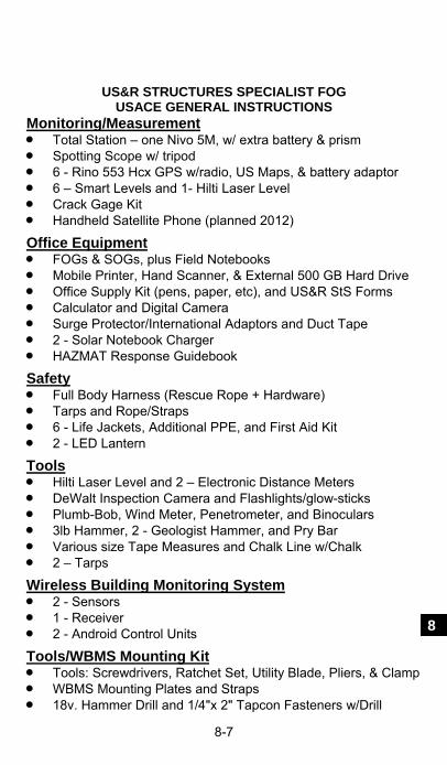
US&R STRUCTURES SPECIALIST FOG USACE GENERAL INSTRUCTIONS
8-7
8
Monitoring/Measurement Total Station – one Nivo 5M, w/ extra battery & prism Spotting Scope w/ tripod 6 - Rino 553 Hcx GPS w/radio, US Maps, & battery adaptor 6 – Smart Levels and 1- Hilti Laser Level Crack Gage Kit Handheld Satellite Phone (planned 2012)
Office Equipment FOGs & SOGs, plus Field Notebooks Mobile Printer, Hand Scanner, & External 500 GB Hard Drive Office Supply Kit (pens, paper, etc), and US&R StS Forms Calculator and Digital Camera Surge Protector/International Adaptors and Duct Tape 2 - Solar Notebook Charger HAZMAT Response Guidebook
Safety Full Body Harness (Rescue Rope + Hardware) Tarps and Rope/Straps 6 - Life Jackets, Additional PPE, and First Aid Kit 2 - LED Lantern
Tools Hilti Laser Level and 2 – Electronic Distance Meters DeWalt Inspection Camera and Flashlights/glow-sticks Plumb-Bob, Wind Meter, Penetrometer, and Binoculars 3lb Hammer, 2 - Geologist Hammer, and Pry Bar Various size Tape Measures and Chalk Line w/Chalk 2 – Tarps
Wireless Building Monitoring System 2 - Sensors 1 - Receiver 2 - Android Control Units
Tools/WBMS Mounting Kit Tools: Screwdrivers, Ratchet Set, Utility Blade, Pliers, & Clamp WBMS Mounting Plates and Straps 18v. Hammer Drill and 1/4"x 2" Tapcon Fasteners w/Drill

US&R STRUCTURES SPECIALIST FOG USACE GENERAL INSTRUCTIONS
8-8
OPERATIONAL CHECKLISTS The following operational checklists define the duties and responsibilities of the Corps Structures Specialist during mission assignments. The lists are intended to be a general summary of actions and may not include all actions required to complete the mission.
ALERT CHECKLIST
An ALERT is a warning message to stand by for possible deployment. PROCEDURES: _____ Confirm message is an ALERT message. _____ Report current availability status. _____ Take Situation Information, including:
- Nature of Disaster - Possible Destination - Duration of Alert - Special Instructions
_____ Check Equipment. _____ Review Structures Specialist policies, procedures, and
technical information. _____ Make preliminary preparations with family. _____ Stand by for further instructions. _____ Stand down from ALERT only upon expiration of alert
period or notification from HQ USACE or US&R Program Manager.

US&R STRUCTURES SPECIALIST FOG USACE GENERAL INSTRUCTIONS
8-9
8
OPERATIONAL CHECKLISTS (continued)
DEPLOYMENT CHECKLIST A DEPLOYMENT message indicates that you are being activated and will deploy to the disaster. PROCEDURES:
Obtain: _____ Point of departure _____ Point of arrival _____ Travel instructions _____ Initial situation briefing _____ Weather and climate conditions _____ Maps of local disaster area (if possible) _____ Reporting instructions
_____ HQ USACE & US&R PM POC _____ Prepare family (See Family Preparedness Checklist). _____ Monitor disaster-related information from local sources. _____ Gather, prepare and pack equipment. _____ Pack clothing and personal items for disaster area climate. _____ Notify Supervisor and Emergency Management POC. _____ Notify home station Critical Incident Stress provider. _____ Move to Point of Departure (POD). _____ At POD, notify HQ USACE and/or the US&R PM of status. _____ Review Triage and Structures/Hazards Evaluation Forms.

US&R STRUCTURES SPECIALIST FOG USACE GENERAL INSTRUCTIONS
8-10
OPERATIONAL CHECKLISTS (continued)
POINT OF ARRIVAL (POA) CHECKLIST The POA will likely be the same location as the Mobilization Area. This is the initial entry point for all disaster response resources. PROCEDURES: _____ Report to Emergency Support Function #3, Public Works and Engineering and/or FEMA IST. _____ Check-in with designated support unit/individual or Corps Cadre Overhead personnel if they have arrived. _____ If no Corps Cadre Overhead personnel, report arrival to HQ USACE EOC or US&R PM. _____ Receive Situation Briefing/Update. _____ Obtain/Retrieve Regular Equipment Cache, if shipped. _____ Await assignment. _____ Obtain food/quarters if required. In some cases, you may be required to move to another location where US&R resources are being marshaled. If so: _____ Obtain transportation to designated area. _____ Execute other actions on this list.

US&R STRUCTURES SPECIALIST FOG USACE GENERAL INSTRUCTIONS
8-11
8
OPERATIONAL CHECKLISTS (continued)
FAMILY PREPAREDNESS CHECKLIST Ensuring that your family is taken care of and is informed about your deployment is an important part of your duties. Some of the items on this checklist need to be taken care of prior to any alert or deployment message. Such items are in italics, and the checklist serves as a verification that you have reviewed them with your family. _____ Will (location, etc.) _____ Power of Attorney (location, scope, and provisions). _____ Contact number at HQ USACE or USACE US&R Program Office. _____ Employee Assistance Program telephone number. _____ Critical Incident Stress Management (CISM) information.

US&R STRUCTURES SPECIALIST FOG USACE GENERAL INSTRUCTIONS
8-12
OPERATIONAL CHECKLISTS (continued)
ASSIGNMENT CHECKLIST The ASSIGNMENT is when you have been assigned to a specific Task Force, Unit, or Team. PROCEDURES: _____ Report to Unit/Task Force Leader. _____ Obtain mission/assignment briefing. _____ Obtain support information. _____ Review Unit Chain of Command. _____ Provide Leader overview of capability. _____ Contact other technical resources. _____ Establish work plan in coordination with Unit Leader and
other support resources. _____ Report time and attendance to the Corps US&R Mission
Manager at the IST or DFO. _____ Submit daily “214 Form” reports to the US&R IST
Engineering Cell or the Corps US&R Mission Managers at the end of the duty shift. Reports should contain the following:
_____ Previous day's activities.
_____ Planned activities (next shift) _____ Any problems experienced _____ Any other items/topics of importance _____ Site conditions, date, time, temp, etc.

US&R STRUCTURES SPECIALIST FOG USACE GENERAL INSTRUCTIONS
8-13
8
OPERATIONAL CHECKLISTS (continued)
INCIDENT CHECKLIST The INCIDENT is the actual disaster site, which may be a single or multiple collapse, and may require light, medium or heavy US&R. PROCEDURES: _____ Obtain incident briefing from Incident Commander, IST or Unit Leader.
_____ Obtain pertinent building data (occupancy, special
conditions, citizen reports, etc.). _____ Gather appropriate building plans, etc., as available. _____ Contact local structural engineers, contractors, and/or
building department officials to determine construction data.
_____ Ensure use of all safety practices and procedures. _____ Ensure your physical readiness through proper
nutrition, water intake, rest and stress control techniques. _____ Report any signs/symptoms of critical incident stress
exhibited by yourself/coworkers. _____ Brief your shift replacement fully on all ongoing operations
when relieved at work cycle rotations. _____ Participate in daily briefing. _____ Assist remaining Task Force/Unit members as required. _____ Support other IST missions.

US&R STRUCTURES SPECIALIST FOG USACE GENERAL INSTRUCTIONS
8-14
OPERATIONAL CHECKLISTS (continued)
STRUCTURAL ASSESSMENT CHECKLIST The STRUCTURAL ASSESSMENT is the key function of the Structures Specialist. Detailed references are located in Section 3 of this FOG. PROCEDURES:
_____ Develop building element identification system (Section 1).
_____ Perform Rapid Structural Triage operations as directed: - Concise ID/location of structures and monitoring
equipment. - Identify monitoring equipment used by description or serial number. - Rapid assessment of the affected area. - ID potential buildings that require more detailed assessment/search. - Use the Rapid Structural Triage Form to capture information.
_____ Perform an assessment of the assigned structures'
exterior and interior to determine structure type, location of falling or collapse hazards, and access points. This would include: - Clearly mark the structure(s) assessed at the point of entry in accordance with the standard marking system. - Draw a crude plan to indicate possible access points, location of structural hazards and the most productive methods of hazard reduction. - Note the indication of normal egress routes (i.e., corridors, stairs, etc.) for any possible voids or victim locations. - Clearly mark off hazardous areas that are to be avoided. - Use the Structure/Hazards Evaluation Form to capture information.
US&R STRUCTURES SPECIALIST FOG USACE GENERAL INSTRUCTIONS
8-15
8
OPERATIONAL CHECKLISTS (continued) STRUCTURAL ASSESSMENT CHECKLIST (continued) _____ Provide assessment to Task Force/Team Leader,
including: - Recommendations for areas requiring hazard mitigation:
- Shoring and bracing - Removal - Monitor with warning escape system - Avoidance - Discuss the most productive method of access relative to probable location of victims
_____ Work with search and rescue personnel. Brief team on
structural considerations. Mark building in accordance with the Structure/Hazards Evaluation and Search Assessment procedures. Determine the most appropriate course of action to gain access to victims, including: - Most appropriate routes to conduct searches. - Available tools and shoring materials. - Structural materials likely to be found while gaining access. - Effects of rescue operations on other building elements. - Special precautions required during breaching operations. - Special considerations for buildings with basements. - Advice on the placement of shoring and bracing. - Monitor the assigned structures for changing conditions.
_____ Re-assess structures as required.

US&R STRUCTURES SPECIALIST FOG USACE GENERAL INSTRUCTIONS
8-16
OPERATIONAL CHECKLISTS (continued)
DEMOBILIZATION CHECKLIST DEMOBILIZATION refers to all of the actions from disengaging from the last US&R incident through out-processing and your return home. PROCEDURES:
UNIT & MOB AREA _____ Conduct out-brief with IST Engineering Cell or Unit Leader. _____ Re-supply of issued equipment if required. _____ Return unit/team equipment & Regular Equip. Cache. _____ Check-out from unit. _____ Report to Corps Overhead personnel. _____ Participate in CISM debriefing. _____ Participate in any mission out-briefs or after-action
sessions conducted by US&R managers and/or host jurisdiction.
_____ Return to home duty station.
HOME DUTY STATION _____ Attend CISM aftercare sessions. _____ Prepare and submit After-Action Report to Emergency
Management POC and the US&R PM.

US&R STRUCTURES SPECIALIST FOG USACE GENERAL INSTRUCTIONS
8-17
8
SYSTEM DESCRIPTION
FEMA US&R TASK FORCES MISSION: Heavy Rescue STRENGTH: 70 positions / 24-hour operations AUGMENTATION: DoD Liaison Team (4 Personnel) AREA OF OPERATIONS: Single Incident or Geographic Area STRUCTURES SPECIALIST: 2/Task Force DATA: Multi-disciplinary Task Force Self Contained for 72 hrs. Extensive Medical & Equipment Cache Organic Internal Communications Extensive & Specialized Rescue Training

US&R STRUCTURES SPECIALIST FOG USACE GENERAL INSTRUCTIONS
8-18
SYSTEM DESCRIPTION (continued)
FEMA US&R TASK FORCE (continued)
US&R STRUCTURES SPECIALIST FOG USACE GENERAL INSTRUCTIONS
8-19
8
SYSTEM DESCRIPTION (continued)
CORPS US&R Trains and maintains cadre of Structures Specialists using specialised equipment. Corps US&R StS Cadre is a HQ USACE resource. The StS Cadre is managed by the US&R Program Manager. After coordination with the FEMA IST or DoD, the StS Cadre will be activated upon order from HQ USACE and the US&R Program Manager will assist with their notification and mobilization. The ENGLink system will indicate the available StS Red, White, or Blue Strike Team that is on call each month. All 3 Strike Teams may be activated depending on the type and size of the response. HQ USACE UOC will conduct StS Cadre notification and mobilization in the event that the US&R Program Manager is unable to fulfill that function. By direction of HQ USACE, operational overhead and management support will be provided by US&R Program Manager. Upon arrival at the Mobilization Area, Structures Specialists assignments will be coordinated through the IST or the DFO. Upon assignment, Structures Specialists will operate under the tactical control of the IC or Unit/Task Force Leader. Logistical support will be provided by the receiving unit with DoD support if needed. Corps Overhead personnel may be assigned to assist StS Cadre members with mobilization and demobilization.

US&R STRUCTURES SPECIALIST FOG USACE GENERAL INSTRUCTIONS
8-20
SYSTEM DESCRIPTION (continued)
INCIDENT COMMAND SYSTEM GENERAL: The Incident Command System (ICS) is a standardized incident management system that provides maximum flexibility in providing resources in a changing situation. ORGANIZATION: The basic ICS organization is divided into 4 sections working under the direction of the Incident Commander (IC) and General Staff. Incident Commander: The IC is responsible for all incident activities, including ordering and releasing of resources. General Staff: The General Staff is comprised of the Safety Officer, Information Officer, Liaison Officer and the Section Chiefs. They provide support to the IC in the management of the incident. Operations Section: This section is responsible for the planning and execution of all operations related to the primary incident mission. Planning Section: This section is responsible for the collection, analysis and dissemination of all information about the incident and resource status. Logistics Section: This section is responsible for providing facilities, services, and materials in support of the incident. Finance Section: This section is responsible for financial and cost analysis aspects of the incident.

US&R STRUCTURES SPECIALIST FOG USACE GENERAL INSTRUCTIONS
8-21
8
SYSTEM DESCRIPTION (continued) INCIDENT COMMAND SYSTEM (continued)
US&R OPERATIONS Below is an example of an ICS Flow Chart in its most basic form. US&R Task Forces normally operate under the Operations Section:

US&R STRUCTURES SPECIALIST FOG USACE GENERAL INSTRUCTIONS
8-22
SYSTEM DESCRIPTION (continued) INCIDENT COMMAND SYSTEM (continued)
ICS TERMINOLOGY Agency Representative. Reporting to the Liaison Officer, this individual represents their agency and has the authority to make decisions on all matters regarding the agency's participation in the incident. Allocated Resources. Resources dispatched to an incident that have not yet checked in with the Incident Communications Center. Assigned Resources. Resources checked in and assigned work tasks on an incident. Available Resources. Resources assigned to an incident and available for an assignment. Base. That location at which the primary logistical functions are coordinated and administered. Branch. The organizational level having a geographic/functional responsibility for major parts of incident operations. It is between the Section and Division/Group levels. Dispatch. The implementation of a command to move a resource(s) from one place to another. Dispatch Center. A facility where resources are directly assigned to an incident.

US&R STRUCTURES SPECIALIST FOG USACE GENERAL INSTRUCTIONS
8-23
8
SYSTEM DESCRIPTION (continued) INCIDENT COMMAND SYSTEM (continued)
ICS TERMINOLOGY (continued) Division. That organizational level having responsibility over a defined geographic area. It sits between the Strike Team/Task Force and the Branch. Group. A functionally organized Division (i.e., Rescue, Fire Suppression). Helibase. A location within the incident area for parking, fueling, maintaining and loading helicopters. Mobilization Center. An off-incident location where resources are temporarily located pending assignment, reassignment, or release. Operational Period. The period of time scheduled for the execu-tion of a given set of operational actions. Staging Area. That location where incident personnel and equipment are assigned on a 3-minute available status. Strike Team. Specified combinations of the same type of resource with common communications and a leader. Task Force. A group of resources with a leader and common communications temporarily assembled for a given mission.

US&R STRUCTURES SPECIALIST FOG USACE GENERAL INSTRUCTIONS
8-24
INSARAG MARKING SYSTEM This is the marking system that was developed by the United Nations, International Search & Rescue Advisory Group. It is used outside of the US for marking structures where SAR operations are taking place. USACE StS may encounter this if serving overseas. The basic symbol consists of a 1 meter by 1 meter square box at the primary access point into any compromised structure. Information will be conspicuously made with florescent color to
permanently identify and mark the structure. Upon entry the name of the Team is written, and the remainder
of the information will be added as the Search and Rescue proceeds.
If another Team relieves the first Team, their name symbol is added as well as the time that they began operations.
When all operations have been completed, the Square will be encircled so that all information is contained within the circle.
HAZARD INFORMATION
Go or No Go (G / N)
# LIVE TEAM # DEAD REMOVED TIME/DATE OF START REMOVED
TIME/DATE OF END PERSONS UNACCOUNTED FOR LOCATION OF OTHER VICTIMS

US&R STRUCTURES SPECIALIST FOG FEMA StS GENERAL INSTRUCTIONS & FORMS
9-1
9
INTRODUCTION to SECTION 9
This section contains information that is useful for all Structures Specialists, and should be reviewed while in transit to an incident.
The Information in Section 9 is presented as follows: Description of Duties Page 9-1 Personal Equipment Checklists 9-2 Operational Checklists and Procedures 9-4 Ten StS Talking Points – What StS can do for T.F. 9-10 Fire Service Uniform Insignia – How to I.D. Leadership 9-10 Structures Spec Forms (small scale examples) 9-11 The Structures Specialist is responsible for performing various structural assessments for the Task Force during incident operations. The Structures Specialist reports directly to the Planning Team Manager, but during operations, will normally be assigned to the Search Team Manager or Rescue Team Manager. DESCRIPTION OF DUTIES
The Structures Specialist is responsible for evaluating the immediate structural condition of the area to be entered at the rescue site during task force operations.
The Structures Specialist is responsible for determining the appropriate type and amount of structural hazard mitigation in order to minimize risks to task force personnel on site.
The Structures Specialist is responsible for cooperating with and assisting search and rescue resources.
The Structures Specialist is accountable for all issued equipment.
The Structures Specialist performs additional tasks or duties as assigned during a mission.

US&R STRUCTURES SPECIALIST FOG FEMA StS GENERAL INSTRUCTIONS & FORMS
9-2
PERSONAL EQUIPMENT CHECKLIST
Due to the need for rapid response to a disaster event, all personnel must have necessary personal clothing, equipment, and supplies readily available for immediate mobilization. Each team member should also pack two weeks of personal prescription medications, over-the-counter medications commonly used for colds, allergies, etc. and extra prescription eye wear. The following list is the suggested minimum requirements to promote individual sufficiency during mission operations:
1. PROVIDED BY TASK FORCE (confirm w/ your Task Force) [ ] UNIFORM-BLOUSE, T-SHIRTS, PANTS; MULTIPLE SETS [ ] RAIN GEAR & BRIEF RELIEFS [ ] COOL WEATHER FLEECE TOPS/BOTTOMS & GLOVES [ ] LONG UNDERWEAR & COOL WEATHER HAT [ ] BOOTS W/ STEEL TOES & SHANK (check for comfort) [ ] FIELD PACK, SLEEPING BAG, & SLEEPING PAD [ ] HELMET W/HEADLIGHT, SAFETY GLASSES, & GOGGLES [ ] DUST MASK, GLOVES, & KNEE PADS [ ] MULTI-PURPOSE TOOL & CHEMICAL LIGHT STICKS [ ] US&R SYSTEM FIELD OPERATIONS GUIDE [ ] SUNSCREEN WIPES & INSECT REPELLENT WIPES [ ] HAND SANITIZER BOTTLE, WATER BOTTLES, & MREs [ ] FIRST AID KIT & CPR MASK StS MISSION SPECIFIC ITEMS: [ ] PORTABLE RADIO W/ HARNESS, GPS & WIND METER [ ] FULL FACEMASK, FILTER CARTRIDGES, & DOSIMETER [ ] PERSONAL ALERT SAFETY SYS (PASS) & DOSIMETER [ ] StS NAPSACK, GPS, COMPASS, & BINOCULARS [ ] CLIPBOARD, NOTEBOOK, PENS/PENCILS, & CRAYONS [ ] KNEEBOARD, WATERPROOF NOTEBOOK/PEN, & COVER [ ] CALCULATOR, SCALES, DRAFTING TRIANGLE, & FORMS [ ] GEOLOGY HAMMER, SPRAY PAINT, & FLAGGING TAPE [ ] CRACK MONITORS, & ANCHORS/ADHESIVES [ ] TOTAL STATION W/TRIPOD, & TAPE MEASURES 200' & 30' [ ] PLUMB BOB, LASER RANGE FINDER, & CLINOMETER [ ] BOB'S RIGGING & CRANE HANDBOOK & CROSBY CARD [ ] METAL DETECTOR

US&R STRUCTURES SPECIALIST FOG FEMA StS GENERAL INSTRUCTIONS & FORMS
9-3
9
PERSONAL EQUIPMENT CHECKLIST (continued) 2. RECOMMENDED SUPPLEMENTAL TECHNICAL ITEMS [ ] MECHANICS GLOVES & MULTI-PURPOSE TOOL [ ] StS FOG, ATC 20-1 FIELD GUIDE, ALL StS FORMS [ ] DUCT TAPE, LASER POINTER, & SOIL PENETROMETER [ ] DIGITAL CAMERA, EXTRA BATTERIES & STORAGE MEDIA [ ] VOICE ACTIVATED TAPE RECORDER & WHISTLE [ ] POCKET AIR HORN & 3 FT FOLDING TAPE MEASURE 3. ESSENTIAL PERSONAL ITEMS [ ] RAIN GEAR & EXTRA CLOTHING FOR 7 DAYS [ ] CASH, PERSONAL I.D., CREDIT CARD, ETC. [ ] PERSONAL HYGIENE & MEDICATION ITEMS [ ] SUN SCREEN, LIP BALM, & INSECT REPELLENT [ ] EYEGLASSES, SAFETY GLASSES, + EXTRAS [ ] PERSONAL MEDICAL & MEDICAL INSURANCE INFO [ ] NON COTTON UNDERWEAR, INC BOOT SOCKS 4. RECOMMENDED SUPPLEMENTAL PERSONAL ITEMS [ ] EMERGENCY PHONE NUMBERS, POCKET NOTE PAD [ ] CELL PHONE & PERSONAL ELECTRONICS + CHARGER [ ] INEXPENSIVE WRIST WATCH & SUN GLASSES [ ] BANDANNAS, AND/OR CLOTH NECK SHIELD [ ] NAIL CLIPPERS & BLISTER REPAIR KIT [ ] MOUTHWASH (small bottle) or BREATH STRIPS [ ] LAUNDRY SOAP (small quantity) [ ] SYNTHETIC ABSORBENT TOWEL [ ] PEPERMINT OIL (to avoid scene odors) [ ] LONG UNDERWEAR, COTTON SOCKS [ ] UNDERWEAR, TEE SHIRTS, TROUSERS, HVY SWEATER [ ] WOOL SOCKS, GYM-TYPE SHORTS, SNEAKERS [ ] BALL CAP, SWEAT SUIT, & LIGHT JACKET

US&R STRUCTURES SPECIALIST FOG FEMA StS GENERAL INSTRUCTIONS & FORMS
9-4
OPERATIONAL CHECKLIST UPON ACTIVATION / AT TF ASSEMBLY POINT
[ ] Receive notification of assignment and instructions from the initiating organization. [ ] Establish communications with the assigned Planning Team Manager and receive initial briefing, and determine if IST has been Activated for this incident [ ] Monitor disaster-related information from local sources. [ ] Gather relevant data on building construction in disaster area. [ ] Review the personal equipment checklist. Assess your personal gear readiness for the specific disaster area climate. Make necessary changes. [ ] Report to the assigned assembly point at the prescribed time. [ ] Forward an accurate Responder Information Sheet to the Medical Team Manager. [ ] Identify immediate TF supervisor. Initiate and maintain the organizational structure integrity of the Search Team through- out all phases of the mission. [ ] Assist with the transfer and loading of the task force equip. [ ] Brief TF personnel on building construction/considerations to be anticipated in the affected area. [ ] Review operation of equipment (electronic level, total station, distance measuring tools, metal detector, etc.). [ ] Review all Structures Specialist forms, especially RST (RST-1 & 2) plus Hazard Assessment (HAZ-1, 2, & 3)

US&R STRUCTURES SPECIALIST FOG FEMA StS GENERAL INSTRUCTIONS & FORMS
9-5
9
OPERATIONAL CHECKLIST continued) AT POINT OF DEPARTURE [ ] Assemble for a task force briefing from the Task Force Leader and appropriate officials. [ ] Assist with the movement and loading of equipment. [ ] Ensure that you receive any appropriate issue of gear (radio, functional vest, etc.) pertinent to the position. [ ] Ensure that you have personal day pack, ear plugs, warm clothes for flight. [ ] Ensure that the battery is removed from your portable radio prior to boarding aircraft. IN TRANSIT [ ] Review the latest disaster-related information as it becomes
available. [ ] Review the FEMA US&R Field Operations Guide for information pertinent to your position description, operational check-list, operational procedure, and safety procedures. [ ] Take advantage of available travel time for rest prior to arrival.

US&R STRUCTURES SPECIALIST FOG FEMA StS GENERAL INSTRUCTIONS & FORMS
9-6
OPERATIONAL CHECKLIST (continued) ARRIVAL AT MOBILIZATION CENTER
[ ] Identify cache supplies and equipment that should receive priority for initial movement to the assigned area. Assist as necessary in the departure to the assigned jurisdiction or incident site.
[ ] Brief Rescue Mgr, Search Mgr, Safety Officer, and Heavy Equipment and Rigging Spec of relevant structural concerns.
[ ] Confirm that IST StS position has been filled, and determine coordination and communication protocol with IST StS. ● Request access to Structural, Architectural & Mechanical- Electrical-Plumbing plans. ● Determine number, occupancies, & building construction. ● Determine age & occupancy of structures. ● Determine numbers of people in buildings at time of incident, and how many assumed trapped. ON-SITE OPERATIONS
[ ] If required, assist the Logistics Specialist with the unloading, sorting and set-up of the equipment cache and the task force support facilities. (should not interfere with critical Recon and Triage Tasks).
[ ] Receive initial briefing of tactical assignment from the Task Force Leader or Planning Team Manager to include: ● Incident situation report. ● Task force objectives and tactical assignments. ● TF support layout/requirements (Base of Ops). ● Communications plan. ● Review emergency signaling/evacuation procedures. ● Review medical treatment/evacuation procedures. ● Review process for ordering supplies/equipment. [ ] Carry out tactical assignments as directed. Be prepared to go into immediate operations.

US&R STRUCTURES SPECIALIST FOG FEMA StS GENERAL INSTRUCTIONS & FORMS
9-7
9
OPERATIONAL CHECKLIST (continued) ON-SITE OPERATIONS (continued)
[ ] Conduct Rapid Structure Triage operations as directed: ● Concise ID/location of structures. ● Rapid assessment of the affected area. ● ID potential buildings that require a more detailed assessment/search. ● Use the Rapid Structure Triage Form (see Sec. 8).
[ ] Perform an assessment of assigned structures exterior and interior to determine structure type, location of falling or collapse hazards, and access points. This would include: ● Use StS Checklist Form HAZ-3.
● Seek the following information: Type, age & occupancy of structure Availability of Structural, Arch & MEP plans Layout of bldg & probable location of occupants Location and status of utilities, emergency generators,
fuel tanks, batteries and solar electric systems Pre-existing problems and/or ongoing construction
● Clearly mark the structure(s) assessed at the point of entry in accordance with the standard marking system.
● Draw a crude plan to indicate possible access points, locations of structural hazards, and the most productive methods of hazard reduction. ● Note the indication of all access/egress routes (i.e., corridors, stairs, elevators, duct & pipe access) for possible voids, victim locations, and access. ● Clearly mark off hazardous areas that are to be avoided.
[ ] Participate in RST operations as directed. Task Force on structural considerations. Mark buildings in accordance with the Structure/Hazards Evaluation Marking Sys.
[ ] Gather Structural, Architectural & MEP plans, etc. as available from facilities staff, building officials, engineer of record & contractors. (coordinate this with IST StS).
[ ] Work with HERS to determine availability of heavy equipment and contractors.

US&R STRUCTURES SPECIALIST FOG FEMA StS GENERAL INSTRUCTIONS & FORMS
9-8
OPERATIONAL CHECKLIST (continued) ON-SITE OPERATIONS (continued)
[ ] Provide assessment to TF team managers, including: ● Recommendation for areas requiring hazard mitigation:
Avoid & place barrier tape Minimize Exposure Monitor with warning/evacuation plan Carefully Remove Shore and Brace
● Discuss the most productive method of access relative to probable location of victims.
[ ] Work with search and rescue personnel to determine the most appropriate course of action to gain access to victims. This would include: ● Most appropriate routes to conduct searches. ● Determine what structural materials are likely to be found while gaining access.
● Effects of rescue operations on other building elements. ● Special precautions required during breaching operations. ● Special considerations of buildings with basements. ● Advice on the placement of shoring and bracing material. ● Monitor the assigned structures for changing conditions.
[ ] Ensure your physical readiness through proper nutrition, water intake, rest, and stress control techniques. [ ] Coordinate and communicate all activities with IST Structures Specialist per established protocols. [ ] Keep the Planning Team Manager apprised of any tactical accomplishments or conflicts, supply deficiencies, or equipment malfunctions. [ ] Brief your shift replacement fully on all ongoing operations when relieved at work cycle rotations.

US&R STRUCTURES SPECIALIST FOG FEMA StS GENERAL INSTRUCTIONS & FORMS
9-9
9
OPERATIONAL CHECKLIST (continued) REASSIGNMENT / DEMOBILIZATION [ ] Assemble for a team briefing on the mission status and reassignment/demobilization determinations. [ ] Ensure that assigned tools and equipment are inventoried, returned to the cache, and prepared for movement. [ ] Prepare personal belongings for demobilization. [ ] Notify the Logistics Specialist of losses or potential maintenance requirements of any tools and equipment. [ ] Assist with the break down and policing of the Base of Operations. [ ] Assist with the packaging, movement, and loading of the equipment cache. [ ] Submit personal notes to the Planning Team Manager for inclusion in the after-action reports. This should include reviewing pertinent position descriptions and operational checklists and procedures for recommended changes. [ ] Ensure the return of items issued during the activation phase. [ ] Upon return, participate in the task force mission critique and CISD debriefing.

US&R STRUCTURES SPECIALIST FOG FEMA StS GENERAL INSTRUCTIONS & FORMS
9-10
WHAT CAN StS DO FOR THE TASK FORCE?
1. Identify structural hazards that threaten the safety of rescue personnel.
2. Identify alternatives for Mitigation of Structural Hazards to minimize risks to rescue personnel.
3. Design Mitigation Measures, including shoring and bracing using available materials.
4. Monitor Structural Stability under changing conditions to minimize risks to rescue personnel.
5. Identify potential voids where victims may be located; identify most efficient access route to voids.
6. Provide Orientation and Marking within a structure. 7. Assist with safe placement of Heavy Equipment. 8. Assist Rigger and Rescue Squads with heavy debris removal. 9. Triage collapse areas for Search and Recon operations. 10. Assist Plans with preparation of search maps and IAP.
Liaison with IST and other TF StS for detailed and current building information.
HOW DO YOU KNOW WHO ARE WE TALKING TO? Typical Insignia on Fire Personnel Uniforms
Firefighter I or II - No insignia on the uniform.
Fire Apparatus Engineer - Single silver bugle - West Coast
Lieutenant - Single silver bugle - elsewhere
Fire Captain - Double silver bugles
Battalion Chief -Two crossed gold bugles
Division Chief - Three crossed gold bugles
Deputy Chief - Four crossed gold bugles
Fire Chief or Chief of Department- Five crossed gold bugles

US&R STRUCTURES SPECIALIST FOG FEMA StS GENERAL INSTRUCTIONS & FORMS
9-11
9
FEMA STRUCTURES SPECIALISTS FORMS
The following shows samples of Forms that should be used by FEMA US&R Structures Specialists in order to efficiently document their activities during an incident.
The Forms are arranged as follows: Rapid Structure Triage Forms - RST-1 & RST-2 Structure/Hazard Assessment Forms - HAZ-1 and HAZ-2 Structure/Hazard Assessment Checklist - HAZ-3 Struct Hazard Mitigation - Forms MIT-1 and MIT-Log Landscape Structure Monitoring Forms - MON-1, MON-2,
CP-Log, and MON-Log Portrait Structure Monitoring Log Form - MON-Log-P Struct. Spec. Shift Change Form – Hand-Off Crane Use Form – CU-1 Full size copies of these forms may be downloaded from DisasterEngineer.org in the Library Section.
The use of the Rapid Structure Triage & Structure/Hazard Assessment forms is discussed in Section 6.
MIT-1 is formatted like a Termite Report Form, where a sketch is used as a location map where specific types of Mitigation are located by writing in a Locator Number. This number is then related to a specific type of Mitigation, that is defined in the upper right of the form by an abbreviation. A numerical priority is also assigned to this specific Mitigation. More than one Mitigation may have the same number used to specify its priority. Form MIT-Log is then used to record significant actions taken to complete each of the specific mitigations, and should be used as a communication tool to Hand-off to the oncoming StS.
MON-1, MON-2, CP-Log, & MON-Log in landscape orientation are intended for use with the Total Station. They are used to identify monitoring setup, and to record periodic readings. MON-Log-P (portrait) provides more reading on single sheet. MON-1, MON-Log, & MON-Log-P may be used to record data from other monitoring devices. All MON forms are good docs for Handoff.
Hand-Off and CU-1 are good communication/check list records.

US&R STRUCTURES SPECIALIST FOG FEMA StS GENERAL INSTRUCTIONS & FORMS
9-12

US&R STRUCTURES SPECIALIST FOG FEMA StS GENERAL INSTRUCTIONS & FORMS
9-13
9

US&R STRUCTURES SPECIALIST FOG FEMA StS GENERAL INSTRUCTIONS & FORMS
9-14

US&R STRUCTURES SPECIALIST FOG FEMA StS GENERAL INSTRUCTIONS & FORMS
9-15
9

US&R STRUCTURES SPECIALIST FOG FEMA StS GENERAL INSTRUCTIONS & FORMS
9-16

US&R STRUCTURES SPECIALIST FOG FEMA StS GENERAL INSTRUCTIONS & FORMS
9-17
9

US&R STRUCTURES SPECIALIST FOG FEMA StS GENERAL INSTRUCTIONS & FORMS
9-18

US&R STRUCTURES SPECIALIST FOG FEMA StS GENERAL INSTRUCTIONS & FORMS
9-19
9

US&R STRUCTURES SPECIALIST FOG FEMA StS GENERAL INSTRUCTIONS & FORMS
9-20

US&R STRUCTURES SPECIALIST FOG FEMA StS GENERAL INSTRUCTIONS & FORMS
9-21
9

US&R STRUCTURES SPECIALIST FOG FEMA StS GENERAL INSTRUCTIONS & FORMS
9-22

US&R STRUCTURES SPECIALIST FOG FEMA StS GENERAL INSTRUCTIONS & FORMS
9-23
9

US&R STRUCTURES SPECIALIST FOG FEMA StS GENERAL INSTRUCTIONS & FORMS
9-24

US&R STRUCTURES SPECIALIST FOG FEMA StS GENERAL INSTRUCTIONS & FORMS
9-25
9

US&R STRUCTURES SPECIALIST FOG FEMA StS GENERAL INSTRUCTIONS & FORMS
9-26
214-Unit Log Form