field observation of soil displacements resulting due
TRANSCRIPT

Journal of Engineering Volume 22 May 2016 Number 5
11
Field Observation of Soil Displacements Resulting Due Unsupported
Excavation and Its Effects on Proposed Adjacent Piles
Dr. Ala Nasir Al-Jorany Ghusoon Sadik Al-Qaisee
Professor Asst. Lecture
College of Engineering - University of Baghdad Institute of Baghdad Technology
[email protected] eng_g76@ yahoo.com
ABSTRACT
Soil movement resulting due unsupported excavation nearby axially loaded piles imposes
significant structural troubles on geotechnical engineers especially for piles that are not designed
to account for loss of lateral confinement. In this study the field excavation works of 7.0 m deep
open tunnel was continuously followed up by the authors. The work is related to the project of
developing the Army canal in the east of Baghdad city in Iraq. A number of selected points
around the field excavation are installed on the ground surface at different horizontal distance.
The elevation and coordinates of points are recorded during 23 days with excavation progress
period. The field excavation process was numerically simulated by using the finite element
package PLAXIS 3D foundation. The obtained analysis results regarding the displacements of
the selected points are compared with the field observation for verification purpose. Moreover,
finite element analysis of axially loaded piles that are presumed to be existed at the locations of
the observation points is carried out to study the effect of excavation on full scale piles
behaviors. The field observation monitored an upward movement and positive lateral ground
movement for shallow excavation depth. Later on and as the excavation process went deeper, a
downward movement and negative lateral ground movement are noticed. The analyses results
are in general well agreed with the monitored values of soil displacements at the selected points.
It is found also that there are obvious effects of the nearby excavation on the presumed piles in
terms of displacements and bending moments.
Key words: excavation, axially loaded pile, deflection, bending moment
ركيسة في التربة الىاتجة عه الحفريات غير المسىذة وتاثيرها على عه الازاحاتالموقعية ظات حالملا
مجاورة افتراضية
غصون صادق القيسي
د. علاء واصر الجوراوي
أعخبر ذسط غبػذ
جبؼت بغذاد -و١ت اذعت اجبؼت اخم١ت اعط – /بغذادؼذ حىج١ب
الخلاصة
ذة , ا الاصادت اجبب١ت خشبت ابشئت ػ اذفش٠بث اجبسة غ١ش اغذة راث حبر١ش ػ سو١ضة جبسة ساع١ت ذت
ت حبر١ش الاصادت الافم١ت شبو اشبئ١ت وب١شة ف جبي اذعت اج١حى١ى١ت خبصت ف دبت اشوبئض غ١ش اصت مب
حط٠ش ششع فك امخشح اشبؤ فاربء حف١ز اػبي اذفش٠بث 0.0 بؼكذفش٠بث الؼ١ت ا خببؼت اػبيح خشبت .
اذفش٠بث دي الاسض عطخ ػ اخخبسة اشالبت امبط ػذد حزب١ج ح. ششق ذ٠ت بغذاد ف اؼشاق اج١ش لبة
اذفش , ػ١بث أربء غخش بشى ٠ 32 مبط خلاي الادذار١بث ابع١ب , عجج خخفت أفم١ت بغبفبث فك الؼ١ت
خبئج مبست ح. ( PLAXIS) ابلاوغظ بشبج ببعخخذا اذذدة اؼبصش ظش٠ت ببعخخذاع١ش ػ١بث اذفش ح حز١
ببلاضبفت ا رهاخذمك غشض ا١ذا١ت اشالبت غ اذذدة مبطببلاصادبث ٠خؼك ف١ب ػ١ب اذصي ح اخ اخذ١

Journal of Engineering Volume 22 May 2016 Number 5
12
عو١ت ػ اشالبت ذساعت حبر١ش اذفش٠بث مبط لغ فظ ف ضؼب ح سأع١ب ذت فشدة مخشدت شوبئض أجش اخذ١
ذفش( حذذد اشالبت الؼ١ت سصذث ػ ا اذشوت اصؼد٠ت اذشوت اجبب١ت الا٠جبب١ت ) ػىظ احجب ا .اشوبئض افؼ١ت
ف دبت اذفش٠بث اضذت اؼك , جت اخش عجج اذشوت ابط١ت اذشوت اجبب١ت اغب١ت )بأحجب اذفش(
. ا٠ضب ذفش٠بث اؼ١مت , بشى ػب فب اشالبت الؼ١ت ذشوت اخشبت اجبب١ت مبط اخخبسة خافمت غ اجبب اؼذد
ش٠بث اجبسة ػ اشوبئض الافخشاض١ت د١ذ الاسادبث ػض الاذبء . بن حبر١ش اضخ ذف
: الحفريات , ركيزة عمودية محملة رأسيا , الهبوط , عزوم الانحناء الكلمات الرئيسية
1. INTRODUCTION
Constructing the foundation of a new structure close to existing adjacent ones is a common
geotechnical problem that is often encountered in practice. Such a problem becomes more
complicated when the new structure requires a deep unsupported excavation such as constructing
open tunnels or deep rafts for high rise buildings. Such type of excavation may cause severe
damages to the adjacent structures resulting due loss of lateral confinement of the foundation
soil. The design of these excavations should include an estimation of the ground movement as
well as stability check of the adjacent buildings. For example, a deep foundation pit nearby a
subway in Taipei was excavated, which caused the line tunnel damages and great economic
losses, Zhang, and Mo, 2014. Fig.1 presents case study of collapsed 13-floor building in
Shanghi, China, Ahmed, 2014 that was due to adjacent deep excavation. Fig.2 shows lateral
deformation of sheet pile nearby excavation in Baghdad, 2015.
The maintaining structural integrity of the pile foundations require the information of these
additional loads, deflections is of great importance. It is also important to study the behavior of
the structures during and after failure in order to expand knowledge of engineers after the
serviceability limits of the structures, Poulos, 1997.
Buildings adjacent to excavation may exhibit several phenomena, Korff, and Mair, 2013:
Pile capacity is reduced as smaller stress levels.
Soil settlement below the base of pile.
The variation of skin friction (negative or positive) due to relative movements of the soil
and the pile shaft.
Rearrangement of load between the piles.
Lateral pile deformations.
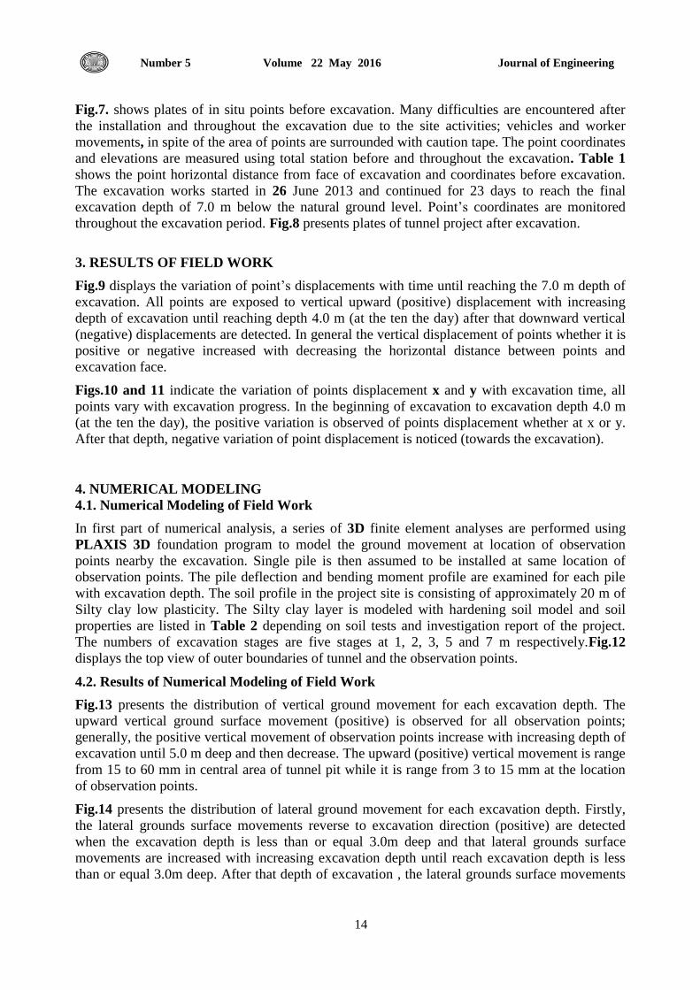
Ong, et al., 2004, examined the case study for a building erected on soil strata including soft
clay subsequent by stiffer soils. Unsupported 5-m deep slope excavation is executed beside a
capped 4-pile group of 0.90m diameter bored piles during the excavation of basement. The piles
were provided with strain gauges and inclinometer. Unfortunately, during the course of
excavation, the slope excavation failed due to heavy rainfall. Fig.3 shows the difference of pile
deflection, lateral soil movements and maximum bending moment on the pile throughout the
excavation. When the lateral movements increased, it causes increasing of induced bending
moment and the pile deflection and the amount of pile deflections was significantly lesser than
the consistent soil movements at the same depth. The measured bending moment override the
ultimate bending moment. Severely damaged of the adjacent piles were observed due to that
extreme soil movements as a result from excavation and were replaced by another group.
Assessment of the influence of excavation on nearby piles is necessary but full scale tests were

Journal of Engineering Volume 22 May 2016 Number 5
13
considered time consuming, and needed additional cost to perform, therefore, centrifuge
modeling technique was adopted to simulate the problem.
Poulos, 2007, exanimated the excavation for new pile cap nearby existing piles in soft to
medium clay with 3.0 m and 10m depth and width of pile cap, respectively. No lateral support
was available for the excavation. The examination showed the maximum bending moment was
significant for the piles adjacent to the excavation. The nearby pile attempted to move upwards
slightly as a result of the excavation as there was no surface pressure, while it settleed when
there was surface pressure. Thus, it would be observed that the bending moment and shear in the
pile were developed due to lateral movement.
The case study for commercial project was carried out on the island of Java, Indonesia; it
included the erection of three buildings: an organization building, a hotel, and a shopping mall.
The investigation details showed the soil strata were soft to very soft silt underneath by firmer
silt. The driven cast-in-situ piles of 0.5 m and 20 m diameter and depth respectively. The ninety
piles are casted for the organization building. An excavation was progressed nearby to the
shopping center where the unbraced excavation closest to the pile group with excavation depth
of 4m. Horizontal movement of the soft silty soil in the direction of the excavation was observed,
and it was difficult to finish the excavation. Stabilization of the excavation was attempted by
steel I-beams, while it was not feasible. Also it was specified that some of the steel I-beams lied
closely to the excavation were shafted more than 1m in the direction of the excavation, thereafter
the building began to incline slightly. The ultimate pile capacity was significantly exceeded the
design capacity due to uncontrolled excavation , Poulos, 2007. Displacement of the corner piles
produces a transfer of the building load to the close columns of the building and causes
additional bending moment in the beam and slab. Thus, cracking of the beams and slab
happened, leading to additional redistribution of building loads to closely columns and slabs, and
then additional cracking. The rigidity of the structure causes the inclination of building and then
an increase of bending moment is caused by the eccentricity of the building load, and the tilting
is worsened. Thus, the initial weakness of the piles as a result of the soil movements that caused
a gradual failure of the foundation and structure throughout duration of 2 - 3 months
approximately is evaluated.
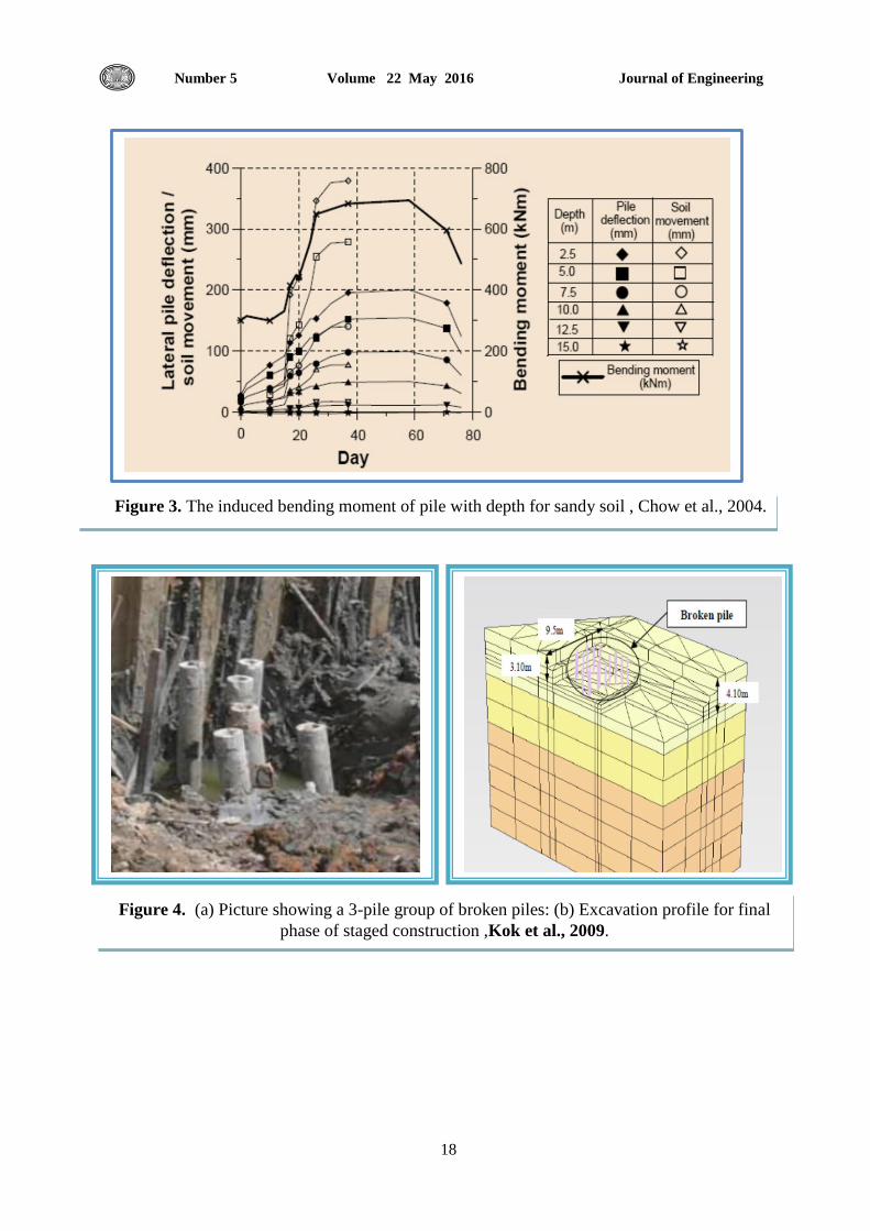
Fig.4a shows the picture of cracked pile group for case study in West Malaysia throughout the
construction of pile cap. Bending moment was developed in piles and leaded to crack and
destroy of piles. PLAXIS 3D FOUNDATION with Hardening-Soil model was adopted to
simulate the behavior of these piles throughout the excavation as shown in Fig. 4b, Kok, et al.,
2009.
In this study, an attempt is made to investigate and evaluate some of the above mentioned side
effects that result due to unsupported excavation.
2. FIELD WORK
The field work during the execution of excavation works for proposed tunnel is 7.0 m deep in the
project of developing the army canal. The site location is close to east of Zayona district in the
east of Baghdad city in Iraq. The project of Zayona tunnel is located between the army canal at
one side and parking at Omar bin Al-Katab street in other side as presented in Fig.5. The tunnel
occupies an approximate area about (45Χ28) m2.
Five observations points are located at two sides close to tunnel boundaries at horizontal distance
that ranges between 1.25-3.25 m from tunnel excavation edges as present in Fig.6.
Journal of Engineering Volume 22 May 2016 Number 5
14
Fig.7. shows plates of in situ points before excavation. Many difficulties are encountered after
the installation and throughout the excavation due to the site activities; vehicles and worker
movements, in spite of the area of points are surrounded with caution tape. The point coordinates
and elevations are measured using total station before and throughout the excavation. Table 1
shows the point horizontal distance from face of excavation and coordinates before excavation.
The excavation works started in 26 June 2013 and continued for 23 days to reach the final
excavation depth of 7.0 m below the natural ground level. Point’s coordinates are monitored
throughout the excavation period. Fig.8 presents plates of tunnel project after excavation.
3. RESULTS OF FIELD WORK
Fig.9 displays the variation of point’s displacements with time until reaching the 7.0 m depth of
excavation. All points are exposed to vertical upward (positive) displacement with increasing
depth of excavation until reaching depth 4.0 m (at the ten the day) after that downward vertical
(negative) displacements are detected. In general the vertical displacement of points whether it is
positive or negative increased with decreasing the horizontal distance between points and
excavation face.
Figs.10 and 11 indicate the variation of points displacement x and y with excavation time, all
points vary with excavation progress. In the beginning of excavation to excavation depth 4.0 m
(at the ten the day), the positive variation is observed of points displacement whether at x or y.
After that depth, negative variation of point displacement is noticed (towards the excavation).
4. NUMERICAL MODELING
4.1. Numerical Modeling of Field Work
In first part of numerical analysis, a series of 3D finite element analyses are performed using
PLAXIS 3D foundation program to model the ground movement at location of observation
points nearby the excavation. Single pile is then assumed to be installed at same location of
observation points. The pile deflection and bending moment profile are examined for each pile
with excavation depth. The soil profile in the project site is consisting of approximately 20 m of
Silty clay low plasticity. The Silty clay layer is modeled with hardening soil model and soil
properties are listed in Table 2 depending on soil tests and investigation report of the project.
The numbers of excavation stages are five stages at 1, 2, 3, 5 and 7 m respectively.Fig.12
displays the top view of outer boundaries of tunnel and the observation points.
4.2. Results of Numerical Modeling of Field Work
Fig.13 presents the distribution of vertical ground movement for each excavation depth. The
upward vertical ground surface movement (positive) is observed for all observation points;
generally, the positive vertical movement of observation points increase with increasing depth of
excavation until 5.0 m deep and then decrease. The upward (positive) vertical movement is range
from 15 to 60 mm in central area of tunnel pit while it is range from 3 to 15 mm at the location
of observation points.
Fig.14 presents the distribution of lateral ground movement for each excavation depth. Firstly,
the lateral grounds surface movements reverse to excavation direction (positive) are detected
when the excavation depth is less than or equal 3.0m deep and that lateral grounds surface
movements are increased with increasing excavation depth until reach excavation depth is less
than or equal 3.0m deep. After that depth of excavation , the lateral grounds surface movements

Journal of Engineering Volume 22 May 2016 Number 5
15
reverse to the excavation (positive) are reduced and the negative lateral grounds movements
(towards the excavation) developed below the level of ground surface.
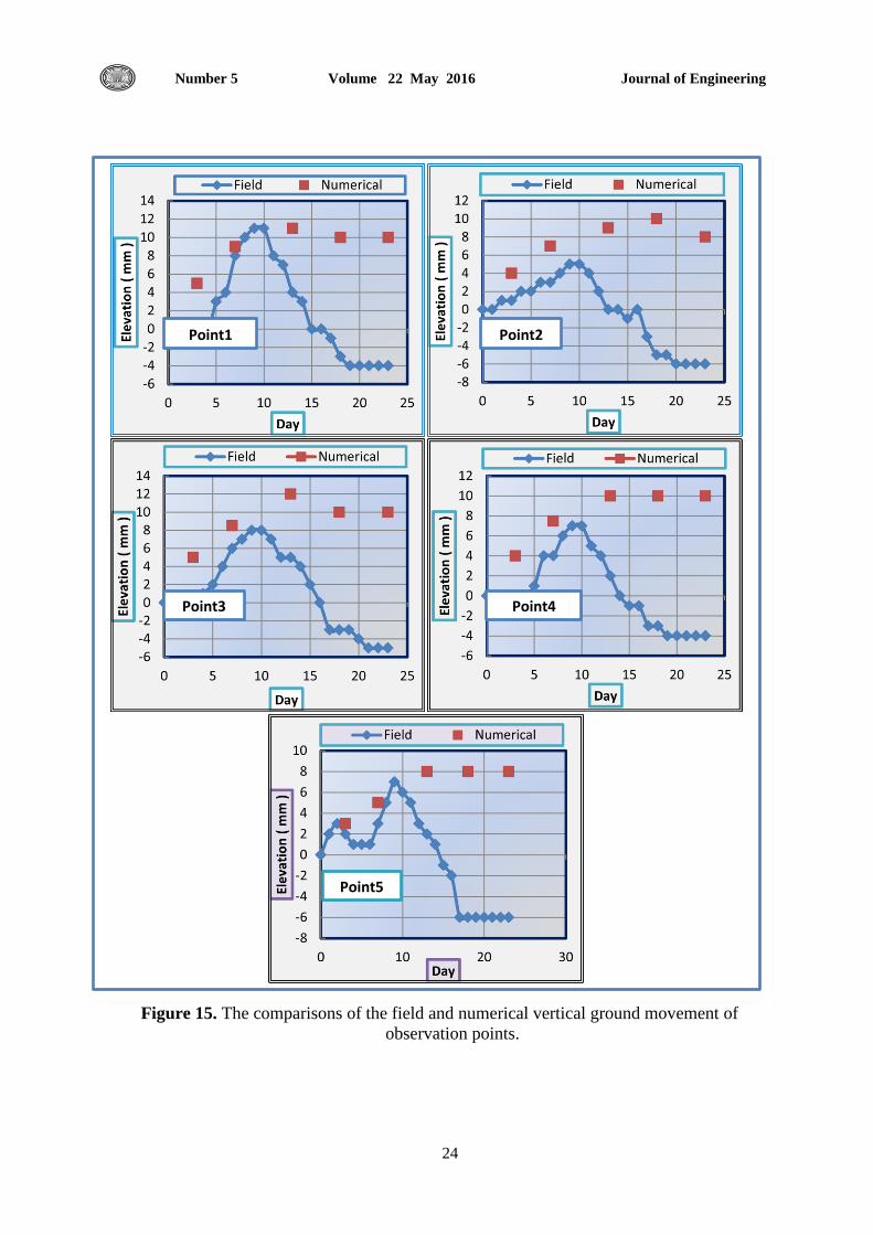
The comparisons are made between the field measurements and numerical analysis regarding the
vertical ground movement of observation points that are shown in Fig. 15. Good agreements are
noticed in distributions and magnitudes for depth about 4-5 m (less than the 10 days); meanwhile
less agreement is observed when the depth of excavation exceeded 5 m (more than the 10 days).
4.3 Numerical Modeling of Large Scale Model Pile Performance
The response of proposed full scale axially single pile was studied due to nearby excavation of
tunnel. Single pile is installed separately at each location of observation points of length and
diameter 13m and 0.28 m respectively of L/deq ratios equal 46. The axial working load is
evaluated about 250 KN.
Fig. 16 and 17 present the variation of pile deflection and bending moment along pile length for
five excavation depths 1, 2, 3, 5 and 7 m and with 1.25m, 2.25m and 3.25 m horizontal distance
from face of excavation. It can be observed that for depth of excavation less than or equal 3.0 m
the pile deflection and bending moment are slightly affected compared to that occur of the
deeper excavation. When the excavation depth is equal or more than 5.0 m (L/2), the pile
deflection is almost changed to be towards the excavation (negative).The pile deflection and
bending moment values decreases with increasing the horizontal distance of excavation for all
depth of excavation as the comparisons present in Fig. 18 and 19 with respect to each depth of
excavation and different horizontal distance of excavation. The maximum deflection is located at
pile head that reached about 8% and 10% of pile diameter for horizontal distance of excavation
3.25m and 1.25m, respectively. The minimum deflection is located at pile tip about 1/3
maximum deflection at pile head. The pile bending moments exhibits double curvature response
when the excavation depth is more than 5.0 m (L/2) for all examined horizontal distance of
excavation 1.25, 2.25 and 3.25 m.
5. CONCLUSIONS
1. Insignificant effect of excavation on pile head deflection and bending moment as the
excavation depth less than half pile length.
2. Noticeable effect of excavation as the excavation depth is equal or more than 5.0 m (L/2) ,the
pile deflection is almost changed to be towards the excavation (negative).
3. The pile deflection and bending moment values decreases with increasing the horizontal
distance of excavation for all depth of excavation.
4. The pile bending moments are exhibited double curvature response when the excavation
depth is more than half pile length (L/2) for all examined horizontal distance of excavation.

Journal of Engineering Volume 22 May 2016 Number 5
16
REFRENCES
Ahmed S.A., 2014, State-of-the-Art Report: Deformations Associated with Deep
Excavation and Their Effects on Nearby Structures, Ain Shams University, Faculty of
Engineering, Structural Engineering Dept. Geotechnical Engineering Group DOI:
10.13140/RG.2.1.3966.9284.
Kok, S. T., Haut, B.K., Noorzaei, j. and Jaafar, M.S., 2009, Modeling of Passive Piles,.
EJGE, Vo. 16 ,Bund P.
Korff, M. and Mair, R.J. , 2013, Response of Piled Buildings to Deep Excavations in Soft
Soils, Proceedings of the 18th International Conference on Soil Mechanics and
Geotechnical Engineering, Paris 2013, 2035-2039.
Ong, D.E.L. Leung, C.F. and Chow, Y.K., 2004, Pile Behavior Behind a Failed
Excavation, International Conference on Structural and Foundation Failures, August 2-4,
2004, Singapore.
Poulos, H. G. and Chen, L. T., 1997, Pile Response Due to Excavation-Induced Lateral
Soil Movement, ASCE, Journal of Geotechnical and Geoenvironmental Engineering,
Vol.123 No.2, pp.94-99.
Poulos, H. G., 2007, The Influence of Construction “Side Effects” On Existing Pile
Foundations, Lane Cove West, NSW, Australia, and Emeritus.
Poulos, H. G., 2007, Ground Movement- A Hidden Source of Loading on Deep
Foundations, DFI Journal Vol. No.1, 37:54.
Plaxis 3D foundation; Material models manual V1.6 (2006).
Zhang, A and Mo, H., (2014) , Analytical Solution for Pile Response Due to Excavation-
induced Lateral Soil Movement, Journal of Information & Computational Science, 1111–
1120.

Journal of Engineering Volume 22 May 2016 Number 5
17
Figure 2. Lateral movement of sheet pile due to nearby deep excavation, Baghdad ,2015.
Figure 1. Failure of a building in China in 2009 that was initiated by a nearby deep
excavation, Ahmed, 2014.
Journal of Engineering Volume 22 May 2016 Number 5
18
Figure 4. (a) Picture showing a 3-pile group of broken piles: (b) Excavation profile for final
phase of staged construction ,Kok et al., 2009.
Figure 3. The induced bending moment of pile with depth for sandy soil , Chow et al., 2004.

Journal of Engineering Volume 22 May 2016 Number 5
19
Parking
Army Canal Canal Excavation
Boundaries
Figure 5. The project of Zayona tunnel at army canal and surrounding activities .
Omar Bin Al-Katab Street
Figure 6. The project of Zayona tunnel at army canal and observation points.
Observation Points
Observation Points
x
y

Journal of Engineering Volume 22 May 2016 Number 5
20
Figure 7. Photos of points installation before excavation of Zayona tunnel at army canal.
Figure 8. Photos of excavation work of Zayona tunnel at army canal project.
Figure 9. Vertical displacement of observation points.

Journal of Engineering Volume 22 May 2016 Number 5
21
Figure 10. X- coordinates variation of observation points.
Figure 11. Y- coordinates variation of observation points.
Figure 12. Top view of tunnel boundaries and on of observation points.

Journal of Engineering Volume 22 May 2016 Number 5
22
Figure 13. Vertical ground movement distribution with excavation depth.
Ex. Dep. =2.0 m
Ex. Dep. =3.0 m
Ex. Dep. =5.0 m
Ex. Dep. =7.0 m

Journal of Engineering Volume 22 May 2016 Number 5
23
Figure 14. Lateral ground movement distribution with excavation depth
Ex. Dep. =2.0 m
Ex. Dep. =3.0 m
Ex. Dep. =5.0 m Ex. Dep. =7.0 m
Journal of Engineering Volume 22 May 2016 Number 5
24
Point1 Point2
Point3 Point4
Point5
Figure 15. The comparisons of the field and numerical vertical ground movement of
observation points.

Journal of Engineering Volume 22 May 2016 Number 5
25
Figure 16. The variation of pile deflection with excavation depth and for each horizontal
distance of excavation.
Figure17. The variation of pile bending moment variation with depth and for each horizontal
distance of excavation.
Ex.Dis=3.25 m
Ex.Dis=1.25 m Ex.Dis=2.25 m
Ex.Dis=3.25 m
Ex.Dis=1.25 m Ex.Dis=2.25 m

Journal of Engineering Volume 22 May 2016 Number 5
26
Figure 18. Comparisons of piles deflection with excavation depth and horizontal distance of
excavation.

Journal of Engineering Volume 22 May 2016 Number 5
27
Figure 19. Comparisons of piles bending moment with excavation depth and horizontal
distance of excavation.

Journal of Engineering Volume 22 May 2016 Number 5
28
Table 1. Location and global coordinates before excavation of observation points.
Point Perpendicular distance
from excavation face, m x y Z
1 1.25 450493.517 3688077.891 33.363
2 2.25 450494.225 3688078.589 33.339
3 1.25 450498.727 3688065.220 33.500
4 2.25 450499.461 3688064.558 33.504
5 3.25 450500.164 3688063.851 33.508
Table 2. Material properties of in situ soil.
Parameter Name Value Unit
Material model Model Hardening soil
model
-
Type of material behavior Type Drained -
Unit weight of soil γunsat 18.0 KN/m3
Young's Modules E ref
50 6500 KN/m2
Eref
oed 6500 KN/m2
Eref
ur 15000 KN/m2
Poisson's ratio ν 0.30 -
Cohesion Cref 75.0 KN/m2
Friction angle ɸ 15.0 °