field and wave electromagneticocw.snu.ac.kr/sites/default/files/note/1001.pdf · 2018-01-30 ·...
TRANSCRIPT

Field and Wave Electromagnetic
Chapter8
Plane Electromagnetic Waves
Electromagnetic Theory 2 2
Introduction (1)
Homogeneous vector wave equation
Time harmonic, unbounded homogeneous medium· Parameter : intrinsic impedance, attenuation constant, phase constant· Skin depth : the depth of wave penetration into a good conductor· Poynting vector : power flux density· plane wave incident normally on a plane boundary· reflection and refraction on a plane boundary· no reflection and total reflection
22
2
7 90 0
8
0 0
0
14 10 , 10
361
3 10
EE
t
c
με
μ μ π ε επ
μ ε
− −
∂∇ − =
∂
= = × = = ×
= ≅ × ⇒
In free space
Let m/s velocity of wave propagation in free space

Electromagnetic Theory 2 3
Introduction (2)
Uniform plane wave: Assuming the same direction, magnitude, phase of fields in infinite
planes the direction of propagation ⊥
Electromagnetic Theory 2 4
Plane Wave in Lossless Media (1)
Homogeneous vector Helmholtz’s equation (assuming time harmonic )
In cartesian coordinates
Uniform plane wave→uniform Ex over plane surface z
j te ω
2 20 0 0 0 00, where [rad/m]E k E k
c
ωω μ ε∇ + = = =
2 2 22 2 2
0 02 2 20 0xE k E k E
x y z
⎛ ⎞∂ ∂ ∂∇ + = ⇒ + + + =⎜ ⎟∂ ∂ ∂⎝ ⎠
⊥
0 0
2 2
2 2
22
2
0 0
0 0
. ) 0, 0
0
( ) ( ) ( )
x x
xo x
jk z jk zx x x
E Ei e
x y
Ek E
z
E z E z E z E e E e
E E
− ++ − + −
+ −
∂ ∂= =
∂ ∂
∂∴ + =
∂∴ = + = +
: ordinary differential equation
where and : arbitrary constant satisfying boundary condition

Electromagnetic Theory 2 5
Plane Wave in Lossless Media (2)
Assume cos(ωt), : real (zero reference phase at z =0)
Phase velocity : the velocity of propagationof an equiphase front
wavenumber
0E+
0( )0 0 0( , ) Re[ ( ) ] Re[ ] cos( )j t k zj t
x xE z t E z e E e E t k zωω ω−+ + + += = = −
0 : constant phaset k z Aω − =
0 0 0
1
: the velocity of propagation of an equiphase front=the velocity of light
p
dzu c
dt k
ωμ ε
= = = =
00
2 2 : number of wavelength in a complete circle
fk
c c
ω π πλ
= = =
Electromagnetic Theory 2 6
Plane Wave in Lossless Media (3)
wave length : 00
2
k
πλ =
00 : traveling wave in the -z directionjk zE e−
0
0
0
0 0
0 00
0 0 0
00
0
0 0 ( )
( ) 0 0
( )10, , 0
( )( ) ( )
1( ) ( ) ( )
120 377
x y z
x
xx y z
jk zxx
y x x
x y z
E j xH yH zHz
E z
E zH H H
j z
E zE e jk E z
z z
kH z E z E z
k
ωμ
ωμ
ωμηωμ η
μη πε
+ + +
+
++ + +
+−+ +
+ + +
∂∇× = = − + +
∂
∂∴ = = − =
∂
∂ ∂= = −
∂ ∂
∴ = = ⇒ =
∴ = ≅ = Ω
: intrinsic impedance of the
00
0
( , ) ( , ) Re ( ) cos( )j ty y
EH z t yH z t y H z e y t k zω ω
η
++ +⎡ ⎤= = = −⎣ ⎦
free space

Electromagnetic Theory 2 7
Doppler Effect (1)
Assume transmitter moves at the velocity of Wave radiated at t=0 arrives at the Rx at t=t1.Wave radiated at t= t arrives at the Rx at t=t2.
the time elapsed at Rx, corresponding to t at Tx is
u
01
rt
c=
1/ 22 22 0 0
2 2 00 2
0
1/ 2
' 12 cos ( )
( ) , 1 cos
1) (1 ) 1
2
rt t t r r u t u t
c c
r u tu t r t t
c r
cf x x
θ
θ
⎡ ⎤= Δ + = Δ + − Δ + Δ⎣ ⎦
⎛ ⎞ΔΔ Δ + −⎜ ⎟
⎝ ⎠
− −
if
2 1' 1 cosu
t t t tc
θ⎛ ⎞Δ = − = Δ −⎜ ⎟⎝ ⎠
u
Electromagnetic Theory 2 8
Doppler Effect (2)
Assume t is period of the time harmonic source
then
1. ) i e t
fΔ =
21
' 1 cos 1' 1 cos
f u u
f fut c cc
θθ
⎛ ⎞ ⎛ ⎞= = +⎜ ⎟ ⎜ ⎟Δ ⎝ ⎠ ⎝ ⎠−∵

Electromagnetic Theory 2 9
TEM Wave (1)
Uniform plane wave characterized by propagating alongz axis → particular case of a transverse electromagnetic wave
General form of TEM wave
satisfies the homogeneous Helmholtz’s equation, provided that
, x yE xE H yH= =
0 0( , , ) yx zjk yjk x jk zj k rE x y z E e E e e e−− −−= =i
2 2 2 2x y zk k k ω με+ + =
x y zk xk yk zk kn
r xx yy zz
⎧ = + + =⎪⎨
= + +⎪⎩
Wave number vector :
Position vector from the origin :
when constant is a plane of constant phase and uniform amplitude for the wave.
n r =i
Electromagnetic Theory 2 10
TEM Wave (2)
0 0 0
0
0
( )
0
( ) ( ) ( ) 0
( ) 0
( ) ( ) (x y z
j k r j k r j k r
j k r
j k x k y k zj k rx
E
E E e E e E e
E
E e
e x y z e j xk ykx y z
− − −
−
− + +−
∇ =
∇ = ∇ = ∇ + ∇ =
→
∴ ∇ =
⎛ ⎞∂ ∂ ∂∇ = + + = − +⎜ ⎟∂ ∂ ∂⎝ ⎠
i i i
i
i
i
i i i i i
∵
i
(Source free)
plane wave is a constant vector
( )
0
0 0
)
( ) 0
0
x y zj k x k y k zy z
j k r
j k r
zk e
jke
j E k e
k E E
− + +
−
−
+
= −
∴− =
∴ = ⇒
i
ii
i
is transverse to the direction of propagation

Electromagnetic Theory 2 11
TEM Wave (3)
Remark : A uniform plane wave propagating in an arbitrary direction is a TEM wave with are normal to
0
0 0 0
1 1( ) ( ) ( ) ( )
1( ) ( ),
1( ) ( )
( )
) ( )
j k r
j k r j k r j k r
H r E r jk E rj j
kn E r n E r
k
H r n E e
A A A
cf E e e E e E
ωμ ωμ
ωμ μηωμ η ε
η
ψ ψ ψ
−
− − −
= − ∇× = − − ×
= × = × = =
∴ = ×
∇× = ∇× +∇ ×
∴∇× = ∇× +∇ ×
i
i i i
where
0 ( )j k rjk E e jkn E r−= − × = − ×i
n and and E H E H⊥ n
Electromagnetic Theory 2 12
Polarization of Plane Waves (1)
Linearly polarizedif) vector of the plane wave is fixed in the x direction
Superposition of two linearly polarized waves→One in the x-direction. The other in the y-direction and lagging in
time phase
set z=0,
E
. ) xi e E xE=
1 2 10 20
1 2
10 20
( ) ( ) ( )
( , ) Re{ ( ) ( ) }
cos( ) cos2
jkz jkz
j t
E z xE z yE z xE e y jE e
E z t xE z yE z e
xE t kz yE t kz
ω
πω ω
− −= + = −
⎡ ⎤= +⎣ ⎦⎛ ⎞= − + − −⎜ ⎟⎝ ⎠
( j implys 90 lagging in time)
1 2 10 20(0, ) (0, ) (0, ) cos sinE t xE t yE t xE t yE tω ω= + = +
90
Electromagnetic Theory 2 13
Polarization of Plane Waves (2)
the tip of the vector → traversing an elliptical locus in the counter clockwise direction
(0, )E t
2
210 2 1
10 20 10
2 2
2 1
20 10
(0, ) (0, ) (0, )cos , sin 1 cos 1
(0, ) (0, )1
E t E t E t
t t tE E E
E t E t
E E
ω ω ω⎡ ⎤
= = = − = − ⎢ ⎥⎣ ⎦
⎡ ⎤ ⎡ ⎤∴ + =⎢ ⎥ ⎢ ⎥⎣ ⎦ ⎣ ⎦
10 20
10 20
if : elliptically polarized
if : circularly polarized
E E
E E
≠=
10 20
1 2
1
,
(0, )tan
(0, )
When the instantaneous angle
E E
E tt
E t
α
α ω−
=
= =
Electromagnetic Theory 2 14
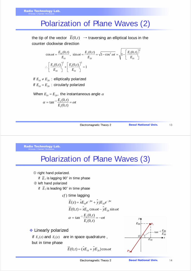
Polarization of Plane Waves (3)
right hand polarized.if is lagging 90° in time phaseleft hand polarizedif is leading 90° in time phase
Linearly polarizedif and are in space quadrature , but in time phase
2E
2E
10 20
10 20
1 2
1
)
( )
(0, ) cos sin
(0, )tan
(0, )
time lagging
jkz jkz
cf
E z xE e y jE e
E t xE t yE t
E tt
E t
ω ω
α ω
− −
−
= +
= −
= = −
2 ( )E z 1( )E z
10 20(0, ) ( ) cosE t xE yE tω= +

Electromagnetic Theory 2 15
Plane Wave in Lossy Media (1)
In a source-free lossy medium
Conventional notation used in transmission-line theory
For a lossless medium,
2 2 0, where c c cE k E k ω με∇ + = =
1/ 2 1/ 2''
1 ' 1'
) ' ''
propagation constant
c c
c
jk j
j j j jj
cf j
γ ω με
σ εγ α β ω με ω μεωε ε
ε ε ε
= =
⎛ ⎞ ⎛ ⎞= + = + = −⎜ ⎟ ⎜ ⎟⎝ ⎠⎝ ⎠
= −
0 ( '' 0, ')σ ε ε ε= = =
0, kα β ω με= = =
2 2 0Then E Eγ∇ − =
Electromagnetic Theory 2 16
Solution → Uniform plane wave propagating in the +z direction
Low loss dielectrics: means a good but imperfect insulator,
0
0
)1 20log 8.69
zx
z j zx
E xE xE e E
cf Np e dB
E E e e
γ
α β αβ
−
− −
= =
= =
⎧= ⇒ ⎨
⎩
assuming that is linearly polarized in the x direction
: attenuation constant (Np/m)Then
: phase constant (rad/m)
'' ' 1 or σε εωε
2
2
'' 1 ''' 1
2 ' 8 '
'' 1 ''' 1
2 ' 8 '
) ' , ''
then
(Np/m),
j j j
cf
ε εγ α β ω μεε ε
ωε μ εα β ω μεε ε
σε ε εω
⎡ ⎤⎛ ⎞= + − +⎢ ⎥⎜ ⎟⎝ ⎠⎢ ⎥⎣ ⎦
⎡ ⎤⎛ ⎞∴ ≅ ≅ +⎢ ⎥⎜ ⎟⎝ ⎠⎢ ⎥⎣ ⎦
= =
Plane Wave in Lossy Media (2)

Electromagnetic Theory 2 17
Intrinsic impedance
phase velocity
1/2
( )
'' ''1 1 :
' ' ' 2 '
,
,
xc
y
j
j t j t
Ej j E H
H
HE H E Ee
E e H e
φ
ω ω φ
μ ε μ εηε ε ε ε
η ηη
−
+
⎛ ⎞ ⎛ ⎞= − + ⇒⎜ ⎟ ⎜ ⎟⎝ ⎠ ⎝ ⎠
= = =
∼ ∼
complex number ( and are not in time phase)
: lagging in time phase,
21 1 ''
18 ''
(m/s)puω εβ εμε
⎡ ⎤⎛ ⎞= ≅ −⎢ ⎥⎜ ⎟⎝ ⎠⎢ ⎥⎣ ⎦
Plane Wave in Lossy Media (3)
Electromagnetic Theory 2 18
Good conductors1
σωε
1/ 2
1/ 22 4
11
2
1) ( )
2
(1 ) , ,
j j
jj j j
j j
jcf j e e
j j f f
π π
σ σγ ω με ω με ωμσ ωμσωε ωε
γ α β π μσ α β σ
⎛ ⎞ += + = =⎜ ⎟
⎝ ⎠+
= = =
∴ = + + = ∝
fα β π μσ= =
4
(1 ) (1 )
,
[ ]
magnetic field lags behind the electric field intensity by 45
cc
j
c c
j fj j
j
eπ
μ μ ωμ π μ αη σε σ σ σω
η η
= ≅ = = + = + Ω−
= °
Plane Wave in Lossy Media (4)

Electromagnetic Theory 2 19
phase velocity
wavelength
2pu
ω ωβ μσ
=
7 7. ) 5.8 10 4 10
720
copper [s/m], [H/m] [m/s] at 3 MHzp
e g
u
σ μ π −= × = ×=
22 ,pu
f f
π πλβ μσ
= = =
6 7 7 4
4
0.24 100( )
(3 10 )(4 10 )(5.8 10 ) 2.64 10
1 110 0.038 38 0.66
2.62
1 1 1
2
3MHz ( ), in the air
(Np/m)
at 3MHz at 10GHz
: skin depth or for good conductor
mm m
m mm m m
f
λ λ
α π π
δ μ μα
λδ δ α βα β ππ μσ
−
−
→ = =
= × × × = ×
= = × = = =
= = = = =∵
Plane Wave in Lossy Media (5)
Electromagnetic Theory 2 20
Note ( )( ) , :
( , )( , )
complex value
cf) mistake
xy c
c
xy
c
E zH z
E z tH z t
ηη
η
=
= ⇒
Plane Wave in Lossy Media (6)

Electromagnetic Theory 2 21
Group Velocity (1)
lossless medium is a linear function of ω
Information-bearing signals : a band of frequencies → waves of the component frequencies travel with different phase velocities → distortion in the signal wave shape → signal disperse →dispersion → lossy dielectric is a dispersive medium.
i.e) Information-bearing signal → small spread of frequencies around a high carrier frequency → group of frequencies → wave packet
Phase velocity (m/s)puωβ
=
β ω με=1
: independent of frequencypuμε
=
Electromagnetic Theory 2 22
Group Velocity (2)
Group velocity : the velocity of propagation of the wave-packet envelope ( a group of frequencies )
Simplest case : wave packet consisting of two traveling waves having equal amplitude and slightly different frequencies phase constants
0 0, ω ω ω ω+ Δ −Δ
∴
,β β β β+ Δ −Δ
( ) ( ) ( ) ( )( ) ( )
0 0 0 0 0 0
0 0 0 0
( , ) cos cos
2 cos cos ,
E z t E t z E t z
E t z t z
ω ω β β ω ω β β
ω β ω β ω ω
⎡ ⎤ ⎡ ⎤= + Δ − + Δ + −Δ − −Δ⎣ ⎦ ⎣ ⎦= Δ − Δ − Δ

Electromagnetic Theory 2 23
Group Velocity (3)
Phase velocity
the velocity of envelope ( group velocity, )
00 0
0
constant, p
dzt z u
dt
ωω ββ
− = = =
gu
1
/
10,
/
g
g
dzt z u
dt
ud d
ωω ββ β ω
ωβ ω
ΔΔ − Δ = = = =
Δ Δ Δ
Δ → =
constant,
2
1, ,
1
pp g
p p p
pg
p
p
dud d du u
d d d u u u d
uu
du
u d
ω ω β ω ωβ β ω ω ω
ωω
⎛ ⎞= = = = −⎜ ⎟⎜ ⎟
⎝ ⎠
=−
Electromagnetic Theory 2 24
Group Velocity (4)
No dispersion
Normal dispersion
Anomalous dispersion
0 ( is independent of , is a linear function of )pp
duu
dω β ω
ω=
g pu u∴ =
0, ( decreasing with )pp
g p
duu
du u
ωω
<
<
0 ( increasing with )pp
g p
duu
du u
ωω
>
>

Electromagnetic Theory 2 25
Poynting Vector (1)
Vector identity
B
Et
DH J
t
⎡ ∂∇× = −⎢ ∂⎢
⎢ ∂∇× = +⎢ ∂⎣
( ) 2
2
2 2
( ) ( ) ( )
1 1
2 2
1
2
1 1( )
2 2
B DE H H E E H H E E J
t t
B HH H H H H
t t t t
DE E
t t
E H H Et
μ μ μ
ε
μ ε
∂ ∂∇ × = ∇× − ∇× = − − −
∂ ∂∂ ∂ ∂ ∂ ⎛ ⎞= = = ⎜ ⎟∂ ∂ ∂ ∂ ⎝ ⎠
∂ ∂ ⎛ ⎞= ⎜ ⎟∂ ∂ ⎝ ⎠∂ ⎛∴∇ × = − +∂ ⎝
i i i i i i
i i i
i
i
where
2Eσ⎞ −⎜ ⎟⎠
Electromagnetic Theory 2 26
Poynting Vector (2)
2 2 21 1( )
2 2s V VE H ds E H dv E dv
tε μ σ∂ ⎛ ⎞× = − + −⎜ ⎟∂ ⎝ ⎠∫ ∫ ∫i
2 2
2 2
1 1
2 2
1 1
2 2
V
E H
E H dvt
E H
ε μ
ε μ
×
∂ ⎛ ⎞− +⎜ ⎟∂ ⎝ ⎠
+
∫
: power flow per unit area
: the rate of decrease of the electric and magnetic energies stored
where, : energy stored in electric and magnetic
2
VE dvσ∫
field
: Ohmic power dissipation or heat
) :
S
P E H
P ds
= ×
∫ i
2 (W/m Poynting vector
: the power leaving the enclosed volume (Poynting theorem)

Electromagnetic Theory 2 27
Poynting Vector (3)
Instantaneous and average power densities.
Assuming phasor ( )0( ) ( ) j j z
xE z xE z xE e α β− += =
* *2 2
*2*2
( )
1 1 1 1,
2 2 2 2
e mS V V
e m
P ds w w dv p dvt
w E E E w H H H
J J Jp E E E
σ
σ
ε ε μ μ
σ σσ σ
∂− = + +
∂
= = = =
= = = =
∫ ∫ ∫i
i i
ii
or
( )0
( )0
0
( , ) Re ( ) Re
( ) ( ) ,
( , ) Re ( )
Then
propagating in a lossy medium in the +z direction
where
j t z j t z
j z jzy
j t
E z t E z e xE e e
EH z yH z y e e e
EH z t H z e y e
η η
ω α ω β
β θ θα
ω
η ηη
η
− −
− +−
−
⎡ ⎤ ⎡ ⎤= = ⎣ ⎦⎣ ⎦
= = =
⎡ ⎤∴ = =⎣ ⎦ cos( )z t zαηω β θ− −
Electromagnetic Theory 2 28
Poynting Vector (4)
* * * * * *
( , ) ( , ) ( , )
Re ( ) Re ( ) Re ( ) ( )
1 1 1) Re( ) Re( ) ( ) ( ) ( ) ( )
2 2 4
j t j t j t
P z t E z t H z t
E z e H z e E z H z e
cf A B A A B B A B A B A B A B
ω ω ω
= ×
⎡ ⎤ ⎡ ⎤ ⎡ ⎤× ≠ ×⎣ ⎦ ⎣ ⎦ ⎣ ⎦
⎡ ⎤× = + × + = × + × + × + ×⎢ ⎥⎣ ⎦
But,
*1
Re2
A B A B⎡ ⎤= × + ×⎢ ⎥⎣ ⎦
220
220
220
0
( , ) ( , ) ( , ) cos( ) cos( )
cos cos(2 2 )
1( ) ( , ) cos
2
z
z
T zav
EP z t E z t H z t z e t z t z
Ez e t z
EP z P z t dt z e
T
αη
αη η
αη
ω β ω β θη
θ ω β θη
θη
−
−
−
∴ = × = − − −
⎡ ⎤= + − −⎣ ⎦
= =∫ 2
(W/m )

Electromagnetic Theory 2 29
Poynting Vector (5)
or * 2
* *
1( , ) Re ( ) Re ( ) Re ( ) ( ) ( ) ( )
21 1
( ) Re ( ) ( ) ( ) Re2 2
j t j t j t
av av
P z t E z e H z e E z H z E z H z e
P z E z H z P z E H
ω ω ω⎡ ⎤⎡ ⎤ ⎡ ⎤= × = × + ×⎣ ⎦ ⎣ ⎦ ⎢ ⎥⎣ ⎦
⎡ ⎤ ⎡ ⎤∴ = × ⇒ = ×⎢ ⎥ ⎢ ⎥⎣ ⎦ ⎣ ⎦2General form (W/m )
Electromagnetic Theory 2 30
Normal Incidence at a Plane Conducting Boundary (1)
1 1
1
( ) , ( )
( ) ( ) ( )
j z j zioi iio
i i i
EE z xE e H z y e
P z E z H z
β β
η− −= =
= ×
In medium 1,
2 20, 0In medium 2, E H= =
Medium 1 Medium 2
1
1 1
0
1 0 0
1 2 1 2 0 0
1
( )
( ) ( ) ( ) ( )
(0) (0) 0 ),
( )
j zr r
j z j zi r i r
t t i r
E z xE e
E
E z E z E z x E e E e
E E E E E E
E z xE
β
β β−
∴
=
∴
= + = +
= = = ∴ = −
=∴
Incident wave is reflected on the boundary
Total field in the medium1
(
1 10
0 1
( )
2 sin
j z j zi
i
e e
x j E z
β β
β
− −
= −

Electromagnetic Theory 2 31
Normal Incident at a Plane Conducting Boundary (2)
1 1( ) ( )No average power since and are in phase quadratureE z H z
1 1
1 1
00
1 1
01 1
1
1 1( ) ( ) ( ) ( )
1( )
( ) ( ) ( ) 2 cos
r r r
j z j zir r
ii r
H z n E z z E z
EH z y E e y e
EH z H z H z y z
β β
η η
η η
βη
= × = − ×
= − =
∴ = + =
* *1Re( ) 0,
2avP E H E H= × = ×∵ cf) : imaginary
Electromagnetic Theory 2 32
Normal Incident at a Plane Conducting Boundary (3)
Space time behavior of the total field
1 0 1
01 1
1
( , ) 2 sin sin
( , ) 2 cos cos
standing wave
i
i
E z t x E z t
EH z t y z t
β ω
β ωη
⎡ =⎢ ⇒⎢ =⎢⎣
( ) ( )
1
11
1
11
( , )
2( , )
( , )2 1 2 1
2 4( , )
zeros of occur at or
Maxima of
Maxima of occur at or
zeros of
E z tz n z n
H z t
E z tz n z n
H z t
λβ π
π λβ
⎫⎪ = − = −⎬⎪⎭
⎫⎪ = − + = − +⎬⎪⎭

Electromagnetic Theory 2 33
Normal Incident at a Plane Conducting Boundary (4)
1 0 0
1
1
00 0
1
r i
ir i
E E E
E
H
EH H
λ
η
⇒ = −
= = ⇒
Note
vanishes on the conducting boundary
vanishes at points of multiples of from the boundary2
is maximum on the conducting boundary
Bound
2
1 1
) .331 ( ( ) )s scf P n H J n H H J
E H
× = × − =
°
1 12 2
ary condition
,
The standing waves of and are in time quadrature (90 phase difference) and are shifted in space by a quarter wave length
Electromagnetic Theory 2 34
Oblique Incidence at a Plane Conducting Boundary (1)
Depending on the polarization of incident wavePlane of incidence : defined by the normal vector to the boundary
and the wave vector: orientation of the incident field
iE can be decomposed into two components : one perpendicular to, and the other parallel to the plane of incidence
Perpendicular polarization
sin cos
: angle of incidencei i i
i
n x zθ θθ
= +
iE E

Electromagnetic Theory 2 35
Oblique Incidence at a Plane Conducting Boundary (2)
For the reflected wave, sin cos : angle of reflection
r r r
r
n x zθ θθ
⎧ = −⎪⎨⎪⎩
11 ( sin cos )0 0
( )0 1 1
( )0
1 1
( , )
sin , cos
1( , ) ( , ) ( cos sin )
i i i
x z
x z
j x zj n Ri i i
j x zi x i z i
j x zii ii i i
E x z yE e yE e
yE e
EH x z n E x z x z e
β θ θβ
β β
β β
β β θ β β θ
θ θη η
− +−
− +
− +
= =
= = =
⎡ ⎤= × = − +⎣ ⎦
i
where
1
1 1
( sin cos )0
sin sin0 0
0 0 1 1
( , )
( ,0) ( ,0) ( ,0) 0
sin sin
at z=0,
hold for all value of x and
: Snell's law of reflection
r r
i r
j x zr r
j x j xi r i r
i r i r
r i
E x z yE e
E x E x E x y E e E e
E E x x
β θ θ
β θ β θ
β θ β θθ θ
− −
− −
=
⎡ ⎤= + = + =⎣ ⎦⇒
= − =∴ =
Electromagnetic Theory 2 36
Oblique Incidence at a Plane Conducting Boundary (3)
1
1
( sin cos )0
( sin cos )0
1 1
( , )
1( , ) ( , ) ( cos sin )
i i
i i
j x zr i
j x zir rr i i
i r
i r
E x z yE e
EH x z n E x z x z e
x H H
z H H
β θ θ
β θ θθ θη η
− −
− −
= −
⎡ ⎤= × = − −⎣ ⎦
component of and are in the same direction
component of and
⎡⎢⎢⎣ are in the opposite direction
1 1 1 1
1
1
cos cos sin sin0 0 1
sin01 1 1
1
( , ) ( , ) ( , )
( ) 2 sin( cos )
( , ) 2 cos cos( cos ) sin sin( cos
i i i i
i
i r
j z j j x j xi i i
j xii i i i
E x z E x z E x z
yE e e e y j E z e
EH x z x z e z j z
β θ β θ β θ β θ
β θ
β θ
θ β θ θ β θη
− − −
−
= +
= − = −
= − +
The total field
1 sin) ij xe β θ−⎡ ⎤⎣ ⎦

Electromagnetic Theory 2 37
Oblique Incidence at a Plane Conducting Boundary (4)
1 1
1 1
1 1
sin cos
cos
Note In the direction normal to the boundary and
standing wave patterns according to and where
No average power is propagated
In the direction
y x
z z
z i
E H
z zβ ββ β θ
→
⇒= →
1 1
1 11 1
1 1 1
2,
sin sin sin
parallel to the boundary and are in both time and
space phase propagate with a phase velocity
The propagating wav
y z
x xx i i x i
E H
uu
λω ω πλβ β θ θ β θ
→
→
= = = = =
1 1 11
1
20 sin( cos ) 0 cos cos , 1,2,3...
2cos
e in the x direction is a nonuniform plane wave
for all x when or
a conducting plate could be inserted at without changi
i i i
i
E z z z m m
mz
πβ θ β θ θ πλ
λθ
= = = = − =
= −
1 0
ng the field
pattern that exists between the conducting plate and the conducting boundary at z=0 TE wave( ) would bounce back and force between the conducting
planes and xE⇒ =
propagate in the x direction
Electromagnetic Theory 2 38
Oblique Incidence at a Plane Conducting Boundary (5)
and have x- and y- component
and have only y- component
i r
i r
E E
H H
1
1
( sin cos )0
( sin cos )0
1
( , ) ( cos sin )
( , )
i i
i i
j x zi i i i
j x zii
E x z E x z e
EH x z y e
β θ θ
β θ θ
θ θ
η
− +
− +
= −
=
Parallel polarization

Electromagnetic Theory 2 39
Oblique Incidence at a Plane Conducting Boundary (6)
The reflected wave
1
1
( sin cos )0
( sin cos )0
1
( , ) ( cos sin )
( , )
r r
r r
j x zr r r r
j x zrr
E x z E x z e
EH x z y e
β θ θ
β θ θ
θ θ
η
− −
− −
= +
= −
0At z=0, for all xtE =
1 1
1 1 1 1 1 1
sin sin0 0
0 0
1
cos cos sin cos cos sin0 0
0
( cos ) ( cos ) 0
( , ) ( , ) ( , )
cos ( ) sin ( )
2
i r
i i i i i i
j x j xi i r r
r i i r
i r
j z j z j x j z j z j xi i i i
i
E e E e
E E
E x z E x z E x z
xE e e e zE e e e
E
β θ β θ
β θ β θ β θ β θ β θ β θ
θ θθ θ
θ θ
− −
− − − −
∴ + =
∴ = − =
∴ = +
= − − +
= −
and
1
1
sin1 1
sin01 1
1
cos sin( cos ) sin cos( cos )
( , ) ( , ) ( , ) 2 cos( cos )
i
i
j xi i i i
j xii r i
x j z z z e
EH x z H x z H x z y z e
β θ
β θ
θ β θ θ β θ
β θη
−
−
⎡ ⎤+⎣ ⎦
= + =
Electromagnetic Theory 2 40
Normal Incidence at a Plane Dielectric Boundary (1)
Assume lossless (σ1=0, σ2=0) media
Incident wave travels in +z directon
1 100
1
( ) , ( ) j z j zii ii
EE z xE e H z y eβ β
η− −= =

Electromagnetic Theory 2 41
Normal Incidence at a Plane Dielectric Boundary (2)
The boundary surface is the plane z=0.→ Discontinuity at z=0 cause that the incident wave is partly reflected back and partly transmitted into medium 2Reflected wave ( )
4 Transmitted wave ( )
We have two unknown thus two equations are required todetermine . Boundary conditions for the electric and magnetic fields
,r rE H
1 100
1 1
1( ) , ( ) ( ) j z j zr
r r rr
EE z xE e H z z E z y eβ β
η η= = − × = −
,t tE H
2 200
2 2
1( ) , ( ) ( ) j z j zt
t t tt
EE z xE e H z z E z y eβ β
η η− −= = × =
0 0,r tE E
0 0,r tE E
Electromagnetic Theory 2 42
Normal Incidence at a Plane Dielectric Boundary (3)
can be positive or negative depending on is always positive→ are in same direction
Γ
0 0 0
00 0
1 2
(0) (0) (0),
1(0) (0) (0), ( ) no current
i r t i r t
ti r t i r
E E E E E E
EH H H E E
η η
+ = + =
+ = − = ∵
2 1 2 10 0
2 1 2 1
2 20 0
2 1 2 1
0 02 1 2
0 2 1 0 2 1
, : Reflection coefficient
2 2 , : Transmission coefficient(Dimensionless)
2 ,
r i
t i
r t
i i
E E
E E
E E
E E
η η η ηη η η η
η ηη η η η
η η ητη η η η
− −∴ =
+ +
=+ +
−Γ = = = =
+ +
2η
τ and i tE E

Electromagnetic Theory 2 43
Normal Incidence at a Plane Dielectric Boundary (4)
The definition for apply even when the media are dissipativei.e) and/or are complex
Relation between reflection and transmission coefficient
and τΓ1η 2η
2 1
2 2* 2 00 02 2
0 2 22 1 2 1 1 12 1 2 1
2*
0 00
1 1
) 1 if
i.e
But
422 4 1 ( 0)
t i
t t i i
t i
ii it t i
i ii i i
cf
E EE H E H
H H
EE EE H E
E EE H E
τ η η
ηη ηη η η η η ηη η η η
η η
> >
⎫> ⎪⇒ × < ×⎬< ⎪⎭
× = × = < − <+ + + +
× = × =
∵
1 τ+ Γ =
Electromagnetic Theory 2 44
Normal Incidence at a Plane Dielectric Boundary (5)
if (i.e medium 2 is perfect conductor)
if , partial reflection
Two parts : A traveling wave with an amplitudeA standing wave with an amplitude
never goes to zero at fixed distance from the interface but has merely locations of minima and maxima
2 0η =
1, 0τΓ = − =
2 0η ≠
1 1
1 1 1
1
1
1 0
0
0 1
1 0 1
( ) ( ) ( ) ( )
(1 ) ( )
(1 ) ( 2sin )
or ( ) ( 2sin )
j z j zi r i
j z j z j zi
j zi
j zi
E z E z E z xE e e
xE e e e
xE e j z
E z xE e j z
β β
β β β
β
β
β
τ β
−
− −
−
−
= + = + Γ
⎡ ⎤= + Γ +Γ −⎣ ⎦
⎡ ⎤= + Γ +Γ⎣ ⎦
⎡ ⎤= + Γ⎣ ⎦
0iEτ
02 iEΓ1 ( )E z∴

Electromagnetic Theory 2 45
Normal Incidence at a Plane Dielectric Boundary (6)
Location of minima and maxima.Assume lossless
1 121 0( ) (1 )j z j z
iE z xE e eβ β−= + Γ
2 1
1 0
1 max
1max
1
1 0
case 1, 0 ( )
the maximum value of ( ) is (1 )
which occurs when 2 2 ( 0)
, 0,1, 2,...2
the minimum value of ( ) is (1 )
i
i
E z E
z n z
nnz n
E z E
η η
β πλπ
β
Γ > >
+Γ
⇒ = − <
∴ = − = − =
−Γ
∵
1 min
1min
1
which occurs when 2 (2 1)
(2 1)(2 1) , 0,1, 2,...
2 4
z n
nnz n
β πλπ
β
⇒ = − +++
∴ = − = − =
Electromagnetic Theory 2 46
Normal Incidence at a Plane Dielectric Boundary (7)
standing wave ratio(SWR), s→expressed in dB scale (20log10 s)
An inverse relation
max
min
1, 1
1
Es s
E
+ Γ= = < < ∞
− Γ
2 1
1 0
max
1 0
min
case 2, 0 ( )
the maximum value of ( ) is (1 )
which occurs at (2 1)
the minimum value of ( ) is (1 )
which occurs at 2
i
i
E z E
z n
E z E
z n
η η
π
π
Γ < <
−Γ
⇒ = − +
+Γ
⇒ = −
1 maxThe location for ( ) when 0 and when 0
are interchanged
E z⇒ Γ > Γ <
1, 1 1
1
s
s
−Γ = − < Γ <
+

Electromagnetic Theory 2 47
Normal Incidence at a Plane Dielectric Boundary (8)
Magnetic field intensity
In lossless medium, is real; will be a minimum at locations where is a maximum, and vice versa.
In medium 2
1 1 1 120 01
1 1
( ) ( ) (1 )j z j z j z j zi iE EH z y e e y e eβ β β β
η η− −= −Γ = −Γ
Γ 1( )H z
1( )E z
2
2
0
02
( )
( )
j zt i
j zt i
E z x E e
H z y E e
β
β
ττη
−
−
⎧ =⎪⎨
=⎪⎩
Electromagnetic Theory 2 48
Normal Incidence at a Plane Dielectric Boundary (9)
1 1
1 1
*
22 20
11
22 220
1
20
1
1 Re
2
( ) Re (1 )(1 )2
Re (1 ) ( )2
Re2
av
j z j ziav
j z j zi
i
P E H
EP z e e
Ez e e
Ez
β β
β β
η
η
η
−
−
⎡ ⎤= ×⎢ ⎥⎣ ⎦
⎡ ⎤= + Γ −Γ⎣ ⎦
⎡ ⎤= −Γ +Γ −⎣ ⎦
=2
2 201
1
220
22
1 2
2 21
2
(1 ) 2 sin 2 (1 )2
( ) ( )2
( ) ( ) for lossless medium
1
i
iav
av av
Ej z z
EP z
P P
βη
τη
η τη
⎡ ⎤−Γ + Γ = −Γ⎣ ⎦
=
=
∴ −Γ =

Electromagnetic Theory 2 49
Normal Incidence at Multiple Dielectric Interface (1)
Reflection occur at both z=0 and z=dTotal electric field in medium 1
1 11 0 0( )j z j z
i rE x E e E eβ β−= +
Electromagnetic Theory 2 50
Normal Incidence at Multiple Dielectric Interface (2)
Er0 is no longer related to Ei0 by Er0=ΓEi0. owing to the existence of a second discontinuity at z=d.The total reflected wave is the result of the initial reflected component and an infinite sequence of multiply reflected contributions within medium 2 that are transmitted back into medium 1.How to find the relation between Er0 and Ei0?One way is to write down the electric and magnetic field intensity vectors in all three regions and apply the boundary conditions.magnetic field in region 1
the electric and magnetic fields in region 2
1 11 0 0
1
1( ) ( )j z j z
i rH z y E e E eβ β
η−= −
2 2
2 2
2 2 2
2 2 22
( )
1( )
j z j z
j z j z
E x E e E e
H y E e E e
β β
β β
η
− ++ −
− ++ −
= +
= −

Electromagnetic Theory 2 51
Normal Incidence at Multiple Dielectric Interface (3)
In region 3
Four unknown,Boundary conditions at two interface give birth to four equations
3
3
3 3
3 33
1
j z
j z
E xE e
H y E e
β
β
η
−+
−+
=
=
0 2 2 3, , , rE E E E+ − +
1 2
1 2
2 3
2 3
(0) (0)At 0,
(0) (0)
( ) ( )At ,
( ) ( )
E Ez
H H
E d E dz d
H d H d
⎧ =⎪= ⎨=⎪⎩
⎧ =⎪= ⎨=⎪⎩
Electromagnetic Theory 2 52
Normal Incidence at Multiple Dielectric Interface (4)
wave impedance of the total field at any plane parallel to the plane boundary
wave impedance of the field, Z(z) : the ratio of the total electric field intensity to the total magnetic field intensity for a z-dependent uniform plane wave.
For the normal incidence of z-dependent uniform plane wave,
( )( ) ( )
( )x
y
Total E zZ z
Total H z= Ω
1 1
1 1
1 0
01
1
( ) ( )
( ) ( )
j z j zx i
j z j ziy
E z E e e
EH z e e
β β
β β
η
−
−
= + Γ
= −Γ
1 1
1 1
11 1
1
( )( ) : function of z
( )
j z j zx
j z j zy
E z e eZ z
H z e e
β β
β βη−
−
+ Γ∴ = =
−Γ

Electromagnetic Theory 2 53
Normal Incidence at Multiple Dielectric Interface (5)
Impedance transformation
The total field in medium 2 is the result of multiple reflections of the two boundary planes at z=0 and z=d; but it can be grouped into a wave traveling in the +z direction and another traveling in the –z direction.
1 1
1 1
1 2 1 1 11 1 1
1 1 1 2 1
2 1 1 2 11
1 2 1 2 1
at z ,
( ) cos sin ( )
( ) cos sin
tan or with
tan
j l j lx
j l j ly
l
E l l j le eZ l
H l e e l j l
j l
j l
β β
β β
η β η βη ηη β η β
η η β η ηηη η β η η
−
−
= −
− ++Γ− = = =
− −Γ +
+ −= Γ =
+ +
2 1 1) If 0 and 1, then ( ) tan
wave impedance of standing wave to the left of perfect conducting
boundary
cf Z l j lη η β= Γ = − − =
Electromagnetic Theory 2 54
Normal Incidence at Multiple Dielectric Interface (6)
The wave impedance of the total field in medium 2 at z=0
Note)As far as the wave in medium 1 is concerned, it encounters adiscontinuity at z=0 and the discontinuity can be characterized by an infinite medium with an intrinsic impedance Z2(0)
2 2
2 2
3 22 2 2 2
3 2
22 2
2
( ) ( ),
( ) ( )
j z j zx
j z j zy
E z E e e
EH z e e
β β
β β
η ηη η
η
−+
+−
−= + Γ Γ =
+
= −Γ
2 2
2 2
2 22 2
2 2
3 2 2 22 2
2 2 3 2
( )( )
( )
cos sin (0)
cos sin
j z j zx
j z j zy
E z e eZ z
H z e e
d j dZ
d j d
β β
β βη
η β η βηη β η β
− −
− −
+ Γ∴ = =
−Γ
+=
+

Electromagnetic Theory 2 55
Normal Incidence at Multiple Dielectric Interface (7)
The effective reflection coefficient at z=0 for the incident wave in medium 1 is
Effect of transform to Z2(0) : inserting a dielectric layer of thickness d and in front of medium 3Given and , can be adjusted by suitable choices of and d
In many applications, and Er0 are the only quantities of interest; hence this impedance transform approach is conceptually simple and yields the desired answers in a direct manner.
If the fields in medium 2 and 3 are also desired, they can be determined by boundary conditions at z=0 and z=d
0 0 2 10
0 0 2 1
(0)
(0)r r
i i
E H Z
E H Z
ηη
−Γ = = − =
+
3η2η
1η 3η 0Γ 2η
0Γ
2 2, and tE E E+ −
Electromagnetic Theory 2 56
Normal Incidence at Multiple Dielectric Interface (8)
Eg) No reflection condition
1 1 1, ,ε μ η 2η 2 2 3, ,ε μ η
d
0 2 1
3 2 2 22 1
2 2 3 2
3 2 1 222 2 1 3 2
The condition of no reflection at interface 0
0 or (0)
cos sin
cos sin
cos cos ....
sin sin ....
z
Z
d j d
d j d
d d
d d
ηη β η βη ηη β η β
η β η βη β ηη β
=⇒ Γ = =
+⇒ =
+
=⎡⎢ =⎣

Electromagnetic Theory 2 57
Normal Incidence at Multiple Dielectric Interface (9)
3 1 2
3 1 2 3 1
22
2
or cos 0
if , can be satisfied when (trivial case of no discontinuities)
or sin 0 or 2
if cos 0, i.e) (2 1
d
nd d
d d n
η η βη η η η η
λβ
β
⇒ = == = =
= =
= = + 2
2 2 1 3
) , 0,1,2,3,..4
sin 0 and can be satisfied when
n
d
λ
β η ηη
=
≠ =
21 3
In summary, two possible conditions
1. when , , 0,1,2,...2
The thickness of the dielectric layer can be a multiple of a half-wavelength
in the dielectric layer Half-wave dielectri
d n nλη η= = =
⇒
21 3 2 1 3
c window (Narrow band device)
2. when , we require , (2 1)4
Quarter-wave impedance transformer
d nλη η η ηη≠ = = +
Electromagnetic Theory 2 58
Oblique Incidence on the Dielectric Boundary (1)
1. TE polarizationDescription of the E-field component Ey
Asssume that wave propagates along z’ axis with dependence
r
'z
z
'x
'x
x
j te ω
'( ', ) Re ( ') , where ( ')j t j zy yE z t E z e E z Aeω β−⎡ ⎤= =⎣ ⎦

Electromagnetic Theory 2 59
Oblique Incidence on the Dielectric Boundary (2)
Assuming displacement vector from origin to any point on a constant phase plane
r
(x,y,z) coordinate for interface
(x',y,z') coordinate for propagation of wave
z' is constant over any plane perpendicular to ' plane wave
the perpendicular distance ' from origin to the consta
z
z
β
⇒⇒
⇒nt phase plane
' 'z z r= i
Vector wave-number : '
Then phase of plane wave : '
z
z r
β β
β β
=
= i
θ
x
z
X’
xβ
zβ
'zβ β=
Z’
Electromagnetic Theory 2 60
Oblique Incidence on the Dielectric Boundary (3)
Boundary condition
, where sin , cosx z x zx z
r xx y y zz
β β β β β θ β β θ= + = =
= + +
( )
'
( , ) x z
x z
j x zy
z r x z
E x y Ae β β
β β β β− +
∴ = = +
∴ =
i
0 0β ω με=E
H
βθ0, Zβ
rβ t
β1 1, Zβ
0 1β ω μ ε=
tθ

Electromagnetic Theory 2 61
Oblique Incidence on the Dielectric Boundary (4)
Boundary condition→Tangential component of E-field at boundary should be continuous
( ,0 ) ( ,0 ) : independent of xy yE x E x− +=
( )
( )
( )1 1
( , ) , where sin , cos
( , ) , where sin , cos
( , ) , where sin , cos
x z
r rx z
t tx z
j x ziy x z
j x zr r ry x r z r
j x zt t ty x t z t
E x z Ae
E x z Be
E x z Ce
β β
β β
β β
β β θ β β θ
β β θ β β θ
β β θ β β θ
− +
− −
− +
= = =
= = = −
= = =
( ,0 ) ( ,0 ) ( ,0 )
( ,0 ) ( ,0 )
i ry y y
ty y
E x E x E x
E x E x
− − −
+ +
= +
=
regardless of x
, : Snell's law
r tx x xj x j x j x
r tx x x
Ae Be Ce
A B C x x x
β β β
β β β
− − −+ =
∴ + = = =
Electromagnetic Theory 2 62
Oblique Incidence on the Dielectric Boundary (5)
If not, change of x leads to the situation that each term be out of phase
, can not have y component since and must lie in the plane
of incidence (Remember B.C.)
r t r t
r tx x x
β β β β
β β ββ
= =
1 0 0 0 1
1 1 1
1
sin sin
sin sin sin sin
sin ,
sin
r r
t t
t p
nv cn
v n u
θ β θ θ θ
β θ β θ ω μ ε θ ω μ ε θ
ε βθθ ε β
= ⇒ =
= ⇒ =
∴ = = = = =
, r tx x xA B C β β β+ = = =
FasterLess dense
SlowerMore dense
1ε ε<
θtθ
tθ θ>
FasterLess dense
SlowerMore dense
tθ
tθ θ>θ

Electromagnetic Theory 2 63
Oblique Incidence on the Dielectric Boundary (6)
1
1
1
Critical angle
90 , sin 1 sin
sin for , sin sin 1
sin
is complex angle
This means no refracted wave. i.e) The incident wave is total
t t c
c tc
t
v
v
βθ θ θβ
β θθ θ θ θβ θ
θ
= ° = ∴ = =
> = = >
∴
⇒
c
t
11 1 11
ly reflected
The angle of incidence which corresponds to the threshold of
total reflection , is called the critical angle.2
sin for or sinc c
n n
n n
θπθ
εθ ε ε θε
−
∴
=
⎛ ⎞= = > = ⎜⎝
⎟⎠
Electromagnetic Theory 2 64
Oblique Incidence at a Plane Dielectric Boundary (7)
Line AO, O’A’, O’B : the intersections of the wavefronts of the incident, reflected and transmitted waves respectively, on the plane of incidence

Electromagnetic Theory 2 65
Oblique Incidence at a Plane Dielectric Boundary (8)
since the phase velocity of the incident and the reflected wave are the same.
' 'OA AO=
'sin 'sin : Snell's law of reflectionr i i rOO OOθ θ θ θ= ⇒ =
1 21sin sinsin
1 1 2
) Boundary condition should be satisfied independent of x
= =
sin sin sin
i trj x j xj x
i r t
cf
e e e
x x x
β θ β θβ θ
β θ β θ β θ
− −−⇒∴ = =
2
2 1 1
2 1 1
1 2 2
'sin' ,
' 'sin
sin , cf) , : Refraction index
sin
pt
p p pi
pt
i p p p
uOOOB AO OB
u u uAO OO
u n cn
u n u u
θθ
θ β ωβθ β
= ∴ = =
= = = = =
Electromagnetic Theory 2 66
Oblique Incidence at a Plane Dielectric Boundary (9)
Note)for non-magnetic media,
→A plane wave incident oblique at an interface with a denser medium will be bent toward the normal.→Snell’s law are independent of polarization
Total reflectionFor : the wave in medium1 is incident on a less dense medium 2
1 2 0μ μ μ= =
1 1 2
2 2 1
sin
sint
i
n
n
θ ε ηθ ε η
= = =
1 2ε ε>
t iθ θ>

Electromagnetic Theory 2 67
Oblique Incidence at a Plane Dielectric Boundary (10)
For , : the refracted wave will be grazing along the interface2
: No refracted wave
the incident wave is totally reflected
i c t
i c
πθ θ θ
θ θ
= =
>
⇒
11 2 2
2 1 1
The angle of incidence , which corresponds to the threshold of total
reflection , is called the critical angle.2
sin let , sin or sin
2 sin
c
t
tt c c
c
n
n
θπθ
θ ε επθ θ θθ ε ε
−
∴
=
⎛ ⎞= = ⇒ = = ⎜ ⎟
⎝ ⎠
Electromagnetic Theory 2 68
Oblique Incidence at a Plane Dielectric Boundary (1)
Perpendicular polarization (TE polarization)
1
1
( sin cos )0
( sin cos )0
1
Incident field
( , )
( , ) ( cos sin )
i i
i i
j x zi i
j x zii i i
E x z yE e
EH x z x z e
β θ θ
β θ θθ θη
− +
− +
=
= − +
Electromagnetic Theory 2 69
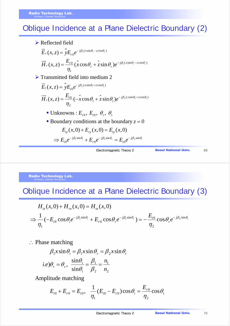
Oblique Incidence at a Plane Dielectric Boundary (2)
1
1
2
( sin cos )0
( sin cos )0
1
( sin cos )0
0
Reflected field
( , )
( , ) ( cos sin )
Transmitted field into medium 2
( , )
( , )
r r
r r
t t
j x zr r
j x zrr r r
j x zt t
tt
E x z yE e
EH x z x z e
E x z yE e
EH x z
β θ θ
β θ θ
β θ θ
θ θη
− −
− −
− +
=
= +
=
= 2 ( sin cos )
2
( cos sin ) t tj x zt tx z e β θ θθ θ
η− +− +
1 21
0 0 r t
sin sinsin0 0 0
Unknowns : , , ,
Boundary conditions at the boundary 0
( ,0) ( ,0) ( ,0)
i tr
r t
iy ry ty
j jji r t
E E
z
E x E x E x
E e E e E eβ θ β θβ θ
θ θ
− −−
=+ =
⇒ + =
Electromagnetic Theory 2 70
Oblique Incidence at a Plane Dielectric Boundary (3)
1 21sin sinsin 00 0
1 2
1 1 2
t 1 1
i 2 2
( ,0) ( ,0) ( ,0)
1( cos cos ) cos
Phase matching
sin sin sin
sin . ) ,
sin
Amplitu
i tr
ix rx tx
j jj ti i r r r
i r t
r c
H x H x H x
EE e E e e
x x x
ni e
n
β θ β θβ θθ θ θη η
β θ β θ β θθ βθ θθ β
− −−
+ =
⇒ − + = −
∴= =
= = =
00 0 0 0 0
1 2
de matching
1 , ( ) cos cosr
i r t i r i t
EE E E E E θ θ
η η+ = − =

Electromagnetic Theory 2 71
Oblique Incidence at a Plane Dielectric Boundary (4)
2 1
0 2 1
2 10 2 1
2
0 2
2 10 2 1
Reflection coefficient
cos cos cos cos
cos coscos cos
22 cos cos
cos cos
cos cos
r i t t i
i i t
t i
t i t
i i t
t i
E
E
E
E
η ηη θ η θ θ θ
η ηη θ η θθ θη
η θ θτ η ηη θ η θθ θ
⊥
⊥
−−
Γ = = =+ +
= = =+ +
Normal Incidence
Oblique Incidence(Perpendicular)
2 1
2 1
η ηη η
−Γ =
+
2 1
2 1
cos cos
cos cos
t i
t i
η ηθ θ
η ηθ θ
⊥
−Γ =
+
1η 1
cos i
ηθ
2η2
cos t
ηθ
Electromagnetic Theory 2 72
Oblique Incidence at a Plane Dielectric Boundary (5)
1 2 1 2
1
2
1 2 0 1 2
1)sin for , (very very rare case)
1
usually ,
For the most of the case there is no Brewester angle
for the TE( ) polarization
Bcf θ ε ε μ μμμ
μ μ μ ε ε
⊥ = = ≠+
= = ≠
∴⊥
22 221 1 2
2 1 1 2 1 222 1 1 20 0
1 2
2
1
Brewster angle : Incident angle for which the reflection coefficient be zero.
cos cos , where cos 1 sin , , , ,
1
sin
B t t ip
B
n cn n
n u
τ
μ ε μ μη θ η θ θ θ η ηε εμ ε
μ εμθ
⊥ ⊥
⊥
⊥
+ Γ =
= = − = = = =
−∴ = 2 1
2
1
2
1
ε
μμ
⎛ ⎞− ⎜ ⎟⎝ ⎠

Electromagnetic Theory 2 73
Oblique Incidence at a Plane Dielectric Boundary (6)
Parallel Polarization (TM polarization)
1
1
( sin cos )0
( sin cos )0
1
Incident field
( , ) ( cos sin )
( , )
i i
i i
j x zi i i i
j x zii
E x z E x z e
EH x z y e
β θ θ
β θ θ
θ θ
η
− +
− +
= −
=
Electromagnetic Theory 2 74
Oblique Incidence at a Plane Dielectric Boundary (7)
1
1
2
( sin cos )0
( sin cos )0
1
( sin cos )0
Reflected field
( , ) ( cos sin )
( , )
Transmitted field
( , ) ( cos sin )
( , )
r r
r r
t t
j x zr r r r
j x zrr
j x zt t t t
t
E x z E x z e
EH x z y e
E x z E x z e
H x z y
β θ θ
β θ θ
β θ θ
θ θ
η
θ θ
− −
− −
− +
= +
= −
= −
= 2 ( sin cos )0
2
t tj x ztEe β θ θ
η− +
0 0 0 0 0 01 2
Boundary condition at 0
1 1 ( ) cos cos , ( )
) The Snell's law as TE applies for TM
i r i t t i r r
z
E E E E E E
cf
θ θη η
=
+ = − =

Electromagnetic Theory 2 75
Oblique Incidence at a Plane Dielectric Boundary (8)
0 2 1
0 2 1
0 2
0 2 1
Reflection coefficient
cos cos
cos cos
2 cos
cos cos
cos 1 (1+ if 0)
cos
r t i
i t i
t i
i t i
ti
i
E
E
E
E
η θ η θη θ η θ
η θτη θ η θ
θτ τ θθ
−Γ = =
+
= =+
⎛ ⎞∴ +Γ = Γ ≠ ≠⎜ ⎟
⎝ ⎠
22
Note)
example : polaroid sunglasses to reduce the sun glare
cf) E-field in parallel to the Earth's surface is predominantly reaching the eye.
Design sunglasses to filter out this
⊥Γ ≥ Γ ⇒
component.
Electromagnetic Theory 2 76
Oblique Incidence at a Plane Dielectric Boundary (9)
221
2 1 22
2 1
2 1 22
1
2
221 2 1 2
2 11
2
1 12 2
1 1
Brewster angle
cos cos , cos 1 sin
1
sin
1
1 For many cases, sin for
1
or tan tan
t B t B
B
B
B
n
n
n
n
η θ η θ θ θ
μ εμ εθεε
εμ μ θ μ μ
ε εεε
εθε
− −
= = −
−=
⎛ ⎞− ⎜ ⎟⎝ ⎠
= ∴ = = =+⎛ ⎞
+ ⎜ ⎟⎝ ⎠
⎛= = ⎜
⎝1 2 for μ μ
⎞=⎟
⎠

Electromagnetic Theory 2 77
Home work
.
8-28, 8-30, 8-32, 8-33, 8-36, 8-42
H W