fiberglass two bed deionizers
TRANSCRIPT

Revised 8/7/09 Form # 999430-FRP
FIBERGLASS TWO BED DEIONIZERS
Systems Built After August 7, 2009 DB-18 DB-24 DB-30 DB-36 DB-42 DB-48
Installation and Operation Manual

Form 999430-FRP Revised 8/7/09
2

Form 999430-FRP Revised 8/7/09
3
TABLE OF CONTENTS
OPERATING DATA……………………….…………..…………. 5 Strong Base Deionizer Specifications……………………. 6 PRE-INSTALLATION DATA
Operating Parameters……………………………….…….. 7 Components of a Deionizer………………………………… 8
DEIONIZATION PROCESS
Deionization…………………………………………………. 9 Regeneration……………………………………………….. 10 Resin Types and Uses…………………………………….. 10 Performance Characteristics……………………………… 11
INSTALLATION
Locating the Equipment………………….….……………… 12 Assembly of the Deionizer……………….….……………… 12 Resin Quantity……………………….…….………………… 13 Minimum Draw Rates……………………….…….………… 13 Typical Installation…………………………………………… 14 Solid State Control Panel………………………………….… 15 Pneumatic Diaphragm Valve Location……………….……. 16 Valve Sequence Chart……………………………….……… 16 Pneumatic Tubing Diagram…………………….…………… 17
REGENERATION CYCLES
Service……………………………………………………….. 18 Cation Backwash Cycle……………………………………. 19 Acid Draw Cycle……………………………….……………. 20 Cation Rinse Cycle………………………….………………. 21 Anion Backwash Cycle……………………………………… 22 Caustic Draw Cycle…………………………………………. 23 Anion Rinse Cycle…………………………………………… 24 Purge Cycle (Rinse to Quality)…………………………….. 25
CHEMICAL USAGE and TIME CYCLES
Regeneration Time Cycles………………………….………. 26 Regeneration Chemical Requirements……………………. 26
Form 999430-FRP Revised 8/7/09
4
TABLE OF CONTENTS
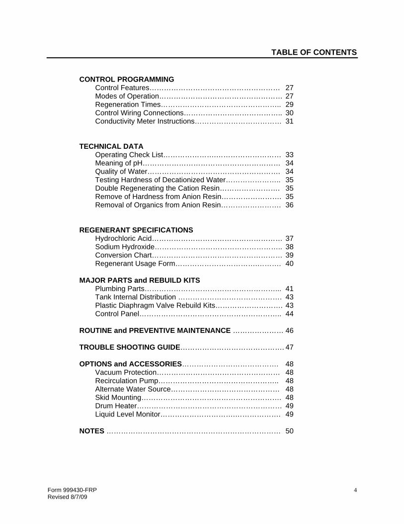
CONTROL PROGRAMMING
Control Features……………………………………………… 27 Modes of Operation…………………………………………… 27 Regeneration Times………………………………………….. 29 Control Wiring Connections………………………………….. 30 Conductivity Meter Instructions……………………………… 31
TECHNICAL DATA
Operating Check List………………….……………………… 33 Meaning of pH………………………………………………… 34 Quality of Water………………………………………………. 34 Testing Hardness of Decationized Water………………….. 35 Double Regenerating the Cation Resin……………………. 35 Remove of Hardness from Anion Resin……………………. 35 Removal of Organics from Anion Resin……………………. 36
REGENERANT SPECIFICATIONS
Hydrochloric Acid……………………………………………… 37 Sodium Hydroxide…………………………………………….. 38 Conversion Chart……………………………………………… 39 Regenerant Usage Form…………………………….………. 40
MAJOR PARTS and REBUILD KITS Plumbing Parts………………………………………………... 41 Tank Internal Distribution ……………………………………. 43 Plastic Diaphragm Valve Rebuild Kits………………………. 43 Control Panel………………………………………………….. 44 ROUTINE and PREVENTIVE MAINTENANCE ………………… 46 TROUBLE SHOOTING GUIDE……………………………………. 47 OPTIONS and ACCESSORIES…………………………………. 48 Vacuum Protection…………………………………………… 48 Recirculation Pump………………………………………….. 48 Alternate Water Source……………………………………… 48 Skid Mounting…………………………………………………. 48 Drum Heater…………………………………………………… 49 Liquid Level Monitor………………………….………………. 49
NOTES ……………………………………………………………… 50

Form 999430-FRP Revised 8/7/09
5
OPERATING DATA Complete the following for future reference upon start-up, it is essential that this information be made available whenever factory technical assistance is requested. Deionizer Model: _____________________________ Single Duplex
Type of Resins: Cation _____________________ Anion ________________________
Quantity of Resin: Cation _______ft3 Anion _______ft3
Date Installed: ______________________ Shipping Order No. _________________________
DI water used for: _____________________________________________________________
Gallons per Day: ___________________ Flow Rate: min _____________ max ___________
Ecodyne Industrial Water Analysis No. used to size system: ____________________________________
Ecodyne Industrial Water Analysis Data: Total Cations _______ ppm Total Anions _______ ppm Cation Capacity _______ grains Anion Capacity _______ grains pH of water _______ Silica _______ ppm Maximum Water Quality based on sodium leakage ___________________ ohms
Mode of Operation: Quality Controlled ___ Manual Controlled ___
Series Regeneration ___ Parallel Regeneration ___
Type of Pretreatment being used _________________________________________________
Regeneration Time Settings:
CATION ANION Regen Cycle Time Regen Cycle Time Backwash Backwash Acid Draw Caustic Draw Rinse Rinse Purge Prior Rinse
Regenerant Chemical used per Regeneration:
Chemical Acid Caustic Gallons Specific Gravity Percentage
Limit Point Setting: ________________ Ohms Note: Caustic Soda must have the temperature maintained between 75O F and 90O F. A heat belt or other heating system is recommended for consistent service runs and silica removal from the resin during regeneration.
Form 999430-FRP Revised 8/7/09
6
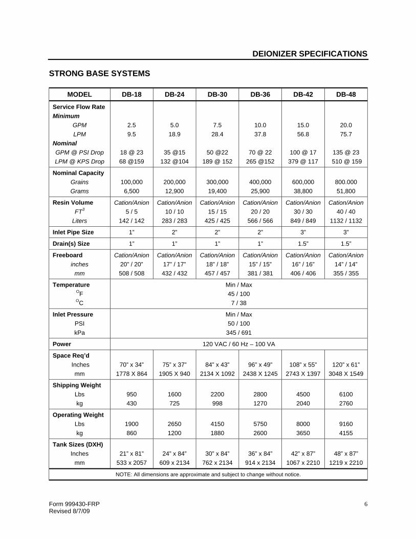
DEIONIZER SPECIFICATIONS STRONG BASE SYSTEMS
MODEL DB-18 DB-24 DB-30 DB-36 DB-42 DB-48
Service Flow Rate Minimum
GPM LPM
Nominal GPM @ PSI Drop LPM @ KPS Drop
2.5 9.5
18 @ 23 68 @159
5.0 18.9
35 @15
132 @104
7.5 28.4
50 @22
189 @ 152
10.0 37.8
70 @ 22
265 @152
15.0 56.8
100 @ 17 379 @ 117
20.0 75.7
135 @ 23
510 @ 159
Nominal Capacity Grains Grams
100,000 6,500
200,000 12,900
300,000 19,400
400,000 25,900
600,000 38,800
800.000 51,800
Resin Volume FT3
Liters
Cation/Anion 5 / 5
142 / 142
Cation/Anion 10 / 10
283 / 283
Cation/Anion 15 / 15
425 / 425
Cation/Anion 20 / 20
566 / 566
Cation/Anion 30 / 30
849 / 849
Cation/Anion 40 / 40
1132 / 1132
Inlet Pipe Size 1” 2” 2” 2” 3” 3”
Drain(s) Size 1” 1” 1” 1” 1.5” 1.5”
Freeboard inches
mm
Cation/Anion 20” / 20” 508 / 508
Cation/Anion 17” / 17” 432 / 432
Cation/Anion 18” / 18” 457 / 457
Cation/Anion 15” / 15” 381 / 381
Cation/Anion 16” / 16” 406 / 406
Cation/Anion 14” / 14” 355 / 355
Temperature OF OC
Min / Max 45 / 100 7 / 38
Inlet Pressure PSI kPa
Min / Max 50 / 100
345 / 691
Power 120 VAC / 60 Hz – 100 VA
Space Req’d Inches
mm
70” x 34”
1778 X 864
75” x 37”
1905 X 940
84” x 43”
2134 X 1092
96” x 49”
2438 X 1245
108” x 55”
2743 X 1397
120” x 61”
3048 X 1549
Shipping Weight Lbs kg
950 430
1600 725
2200 998
2800 1270
4500 2040
6100 2760
Operating Weight Lbs kg
1900 860
2650 1200
4150 1880
5750 2600
8000 3650
9160 4155
Tank Sizes (DXH) Inches
mm
21” x 81”
533 x 2057
24” x 84”
609 x 2134
30” x 84”
762 x 2134
36” x 84”
914 x 2134
42” x 87”
1067 x 2210
48” x 87”
1219 x 2210
NOTE: All dimensions are approximate and subject to change without notice.

Form 999430-FRP Revised 8/7/09
7
PRE-INSTALLATION DATA Read the entire instruction manual before you begin installation. Failure to install and operate the system as required will void the warranty. The system will perform at maximum efficiency, when installed and operated as designed. Obtain all the materials and tools needed for the installation before beginning. Always use the correct tools to install and maintain the system. The installation must conform to local plumbing and electrical codes. Code compliance is the responsibility of the installer or contractor. OPERATING PARAMETERS
Parameter Minimum Maximum
Hardness - 100 Grains per gallon Iron (Ferrous) - 10 ppm Iron (Ferric) - 5 ppm Flow Rate 0.5 gpm / ft3 5.0 gpm / ft3
Chlorine - 0.1 ppm Turbidity - 5 NTU Water Pressure 40 psi 100 psi * Water Temperature 35O F 100O F *** pH 6.8 -
* Maximum pressure dependent on components. *** Higher temperature systems available on special order – consult factory. • Protect the system from pressure extremes. Do not expose the system to surging pressures
or water hammer. Water hammer will cause damage to the control valves, mineral tanks, and plumbing. If a condition of this type exists, a “Water Hammer Arrestor” must be installed to prevent damage.
• Protect the system against backpressure caused by a pump or any type of water storage
system. If pressure on outlet exceeds inlet pressure, resin can be flushed into the inlet water supply during the service cycle.
• When routing the outlet piping to an atmospheric storage tank, a valve or flow control must
be installed in the outlet piping to prevent over running of the system. A backpressure of 15 to 20 psi should be maintained on the system during service.
• Protect the system from freezing weather conditions. Temperatures at and below freezing
will cause damage to tanks, valves and plumbing. Water expands when it freezes and can cause the tanks and plumbing to burst.
• Protect the system from high temperatures in excess of 100O F. Some of the components
used in the manufacture of the system will not withstand high temperatures. Do not connect the system down stream of a hot water system. Also protect the outlet of the system from backup of hot water from a water heater or boiler.

Form 999430-FRP Revised 8/7/09
8
PRE-INSTALLATION DATA • The system operates on 24 Volts AC supplied from a step down transformer using 120 Volts
on the primary side. The 120 volts operates from a normal 15 amp wall outlet receptacle, which is properly grounded. The power reduction transformer supplied with the equipment is UL listed. Conformance to local and National Electrical Codes must be observed and are the responsibility of the installer.
• The system must be located within 10 feet of an open floor drain or sump, which is
connected to a neutralization or other waste treatment system. The drains from the system must contain vents, in accordance with the local plumbing codes. The flow of drain water should be observable. Water deionizers use an eduction system to draw the chemical into the mineral tank. Back-pressure from overhead drain systems can affect the draw rate of the deionizer, therefore; it is not recommended to run the drains any higher that 8 feet above the eductor assembly. On overhead drains, an air gap must be installed in the highest point of the drain line, and local plumbing codes and regulations should be followed.
• It is recommended that inlet and outlet valves be installed on the unit for future service
ability. The inlet and outlet valves are utilized to turn off the water to the unit so that the valves and other components can be serviced.
• Threading compounds and other contaminating materials from the installation of the piping;
must be flushed from the piping prior to allowing water to enter the system. These foreign materials can cause damage to the valves.
COMPONENTS OF A TWO-BED DEIONIZER The system normally is not assembled at the factory. The following should be used as a reference for the correct parts against what was received. Different size units have different quantities of the media and style of internal distributors. All systems 21” through 48” have hub radial lower distributor systems.
2 – Mineral Tanks (Cation and Anion) with internals installed Valve Harness Assembly (includes Failsafe and Purge Valves) Controller with Quality Monitor Strong Acid Cation Exchanger Resin Strong Base Type-2 Anion Exchanger Resin or Weak Base Anion Resin Gravel Underbedding 2 – Draw Tube Assemblies Optional Recirculation Pump (required on duplex systems)
The standard conductivity cell is assembled in the main piping. Special cells are shipped loose for assembly into the piping in the field. Chemical can be drawn directly out of 50-gallon drums if desired. 42” and 48” systems require larger drawtube assemblies because of the quantities of chemical used for regeneration. Skid mounting and pre-assembly is an available option from the factory.

Form 999430-FRP Revised 8/7/09
9
DEIONIZATION PROCESS THE PROCESS OF DEIONIZATION Deionization or demineralization is the process of removing up to 95% of the dissolved minerals such as calcium, magnesium, sodium, manganese, sulfates, chlorides, nitrates and silica from the water supply by way of ion exchange. Dissolved minerals in the water consist of two parts – a metallic part which is a positively charged ion and a non-metallic part which is a negatively charged ion. Two separate resins are utilized for the Deionization process, the cation resin exchanges the positive ions for hydrogen ions (H+) while the anion resin exchanges the negative ions for hydroxide ions (OH-). The Cation Resin is regenerated with Hydrochloric Acid (HCl) and the Anion Resin is regenerated with Sodium Hydroxide (NaOH) also know as caustic soda. The raw water enters the top of the first column and flows down through the resin. The Cationic part of the dissolved minerals in the raw water is exchanged for Hydrogen (H)+ as the water passes through the Cation Resin. The water then flows out the bottom of the first column and into the top of the second column and flows down through the Anion Resin. The Anionic part of the dissolved minerals is exchanged for Hydroxide (OH)- as the water passes through the Anion Resin. Since the Cations were exchanged for Hydrogen and the Anions were exchanged for Hydroxide, the water exiting the bottom of the Anion Column is pure H2O with most of the minerals removed. Cation and Anion resins like certain ions better than others, this phenomenon is called the resin’s affinities. The chart to the right shows the Strong Acid Cation Resin Affinities and the Strong Base Anion Affinities
CATION ANION
Cations: Ammonium (NH4)+
Sodium (Na)+
Potassium (K)+
Magnesium (Mg)++
Calcium (Ca)++ Ferrous Iron (Fe)++ Copper (Cu)++ Zinc (Zn)++ Aluminum (Al) +++ Chrome (Cr)+++ Ferric Iron (Fe)+++ Hydrogen (H)+
Anions: Chloride (Cl)- Bicarbonate (HCO3)- Nitrate (NO3)- Bisulfate (HSO4)- Carbonate (CO3)- Silicate (SiO3)- Sulfate (SO4)- Carbon Dioxide (CO2) Silica (SiO2) Hydroxide (OH)-
H2O
Cation Affinities Anion Affinities Aluminum Sulfate
Iron Carbonate Calcium Nitrate
Magnesium Chloride Potassium Bicarbonate
Sodium Silica

Form 999430-FRP Revised 8/7/09
10
DEIONIZATION PROCESS REGENERATION Hydrogen rich acid passes down through the Cation resin bed during the regeneration cycle. The other positively charged ions (calcium, magnesium, sodium, etc.) are forced off the resin and are replaced with hydrogen ions. These hydrogen ions attach themselves to the negatively charged sites on the resin beads. Hydroxide rich caustic soda passes down through the Anion resin bed during the regeneration cycle. The other negatively charged ions (sulfate, chlorides, carbonate, etc.) are forced off the resin and are replaced with hydroxide ions. These hydroxide ions attach themselves to the positively charged sites on the resin beads. Two-bed deionizers can be regenerated in sequence or simultaneously. Sequential Regeneration is the process by which the Cation Resin is backwashed, injected with chemical, then rinsed then, the Anion is backwash, injected with chemical, and rinsed, one followed by the other. Simultaneous Regeneration has both the Cation and Anion going through the regeneration cycles at the same time. Soft or De-cationized water must be supplied to the Anion Column during Simultaneous Regeneration. The hardness in the raw water can foul the Anion Resin, so it must be removed prior to entering the Anion Column. RESIN TYPES and USES Ecodyne Industrial’s Deionizers are supplied with Strong Acid Cation Resin and Type II Strong Base Anion resin or Weak Base Anion resin. Strong Acid Cation Resin – is especially suited for the cation removal in high purity water demineralization. This resin possesses high exchange capacity combined with excellent chemical and physical stability under a wide range of operating conditions. Used in both Two Bed Deionizer and Mixed Bed Deionizer applications. Weak Base Anion Resin – is used when carbon dioxide or silica is not required to be removed from the water. Weak base resins are generally higher in acid-removing capacity than strong base resins and are generally more stable at higher temperatures. Used primarily in Two-Bed Deionizer applications. Type II Strong Base Anion Resin – removes mineral acids efficiently, and is stable at temperatures up to 105O F. Used primarily in Two-Bed Deionizer applications.

Form 999430-FRP Revised 8/7/09
11
DEIONIZATION PROCESS DEIONIZER PERFORMANCE CHARACTERISTICS Two-Bed Deionizers normally produce water in the 10,000 ohms to 200,000 ohms range. The quality of water capable of being produced by the deionizer is directly related to the amount of sodium leakage from the Cation column and the Type of Anion Resin being used. The lower the sodium leakage, the higher the quality produced. Example: 1.0-ppm sodium leakage will provide 200,000 ohms from a Strong Base Anion Resin, but 400,000 ohms from a Weak Base Anion Resin. While 2.0-ppm sodium leakage will only yield 100,000 ohms from the strong base and 200,000 ohms from the weak base. The sodium leakage from the Cation column also directly affects the pH of the product water and is one of the factors in determining the amount of silica leakage from a strong base anion resin. The capacity of the cation resin is determined by three factors: the regenerant level (lbs of acid per ft3), and the content of Sodium and Alkalinity in the raw water. At a Hydrochloric Acid dosage of 6 lbs per ft3, 30% Sodium and 50% Alkalinity, the Cation Capacity will be approximately 23,500 grains per ft3. However, on the same raw water (30% Sodium and 50% Alkalinity), by increasing the Acid dosage to 9 lbs per ft3, the capacity will be increased by 10% to 26,000 grains per ft3. The capacity of the strong base anion resin is actually determined by four factors: the regenerant level (lbs of sodium hydroxide per ft3), and the content of Monovalent Ions, Carbonic Acid, and Silica in the raw water. At a Sodium Hydroxide dosage of 6 lbs per ft3, 25% Monovalent ions, 10% Carbonic Acid, and 5% Silica, the Strong Base Anion Capacity is 16,000 grains per ft3. If Silica increases to 10%, the capacity decreases to 15,700 grains per ft3. The capacity of the Anion Resin normally dictates the service run length of the deionizer. The Cation resin usually has more capacity than the Anion. Normally a two-bed deionizer comes with a Cation and an Anion that have the same physical size and quantity of resin. The extra capacity of the Cation can be used to regenerate the Anion in systems using sequential regeneration. During normal operation of a two-bed deionizer, after completion of regeneration, the system rinses to a pre-determined quality (usually 50,000 ohms). During operation the quality will continue to climb until the maximum quality is reached. The Sodium Leakage from the Cation resin as previously noted determines the maximum quality of water. The dumping of Silica, followed by Bicarbonates and Chlorides, indicates the end of the service run. A silica monitor is required if one of the critical factors of operation is silica removal. The pH will drop below 7.0 as the Chlorides start to come through to service. The Chloride leakage can be determined by monitoring the pH of the product water. The graph depicts the normal performance curve for a two-bed deionizer. Notice that the quality will increase slightly just before the end of the run. The water quality will drop until the pre-determined set point is reached, then regeneration is required.
WaterQuality
Length of Service Run
Peak Quality

Form 999430-FRP Revised 8/7/09
12
DEIONIZER INSTALLATION LOCATING THE EQUIPMENT Locate the mineral tanks on a firm foundation preferably concrete. The system should be located near an electrical outlet. The electrical panel must be supplied with a 120 volt 20 amp circuit. Power for the recirculation pump must be run separately. A floor drain to a central waste treatment system should be available near the installation, or a neutralization system installed for the Deionizer. Local plumbing codes apply and special requirements may need to be met when installing the system. ASSEMBLY OF THE DEIONIZER The system is not assembled when shipped. The two tanks are set in place and the piping built to the specific tanks shipped with it. The distribution system is mounted in each tank and shipped assembled inside it. Once the system is built and tested with the control panel, the piping is removed and packaged to prevent damage. The piping will have to be reassembled to the two tanks at jobsite. An option offered is skid mounted and pre-piped. The tanks, piping and Controls are pre-assembled and shipped complete if this option is purchased. Assembly is not required on these systems. • Check the system for broken parts or damage that may have occurred during shipment.
Damage during shipment is considered freight damage and a freight claim should be filed with the freight lines. New parts must be ordered to fix the damaged ones.
• Check the internal distribution system for damage or broken parts. Do not load resin or gravel if parts are of questionable integrity.
• Once the tanks are located and the piping assembled to them, connect the inlet water supply, process water piping and drain lines as shown on the installation drawings that follow. Be sure to install isolation valves on the inlet and outlet of each system. Flush all lines of debris after completing the installation. Connect the drawtube assemblies to the draw connection using the chemical hose provided. The drawtubes are made to be placed in a 50-gallon drum. The chemical can be drawn directly from its container.
• The chemical is drawn into the deionizer system. Therefore, it is critical that the system be supplied with 40 psi of water pressure. Lower pressures provide lower vacuums and the caustic viscosity may not allow the system to draw the proper amount in the proper time.
• Drain lines must be ran a minimum of 3 feet over head to prevent a siphoning action on the chemical drums. A maximum height of 8 feet is also required because of the vacuum requirements. Overhead drains provide backpressure on the system reducing the vacuum created by the injector. The system reacts the same as if it did not have enough water pressure.
• Locate the control panel as shown on page 15. The control may also be wall mounted. The system is equipped with diaphragm valves that are operated with 4-way solenoid valves using air pressure. The air pressure must be 10 psi greater than the water pressure for proper operation of the diaphragm valves. Connect tubing from diaphragm valves to the appropriate 4-way solenoid valve port. Refer to the tubing diagram for proper connections.
Form 999430-FRP Revised 8/7/09
13
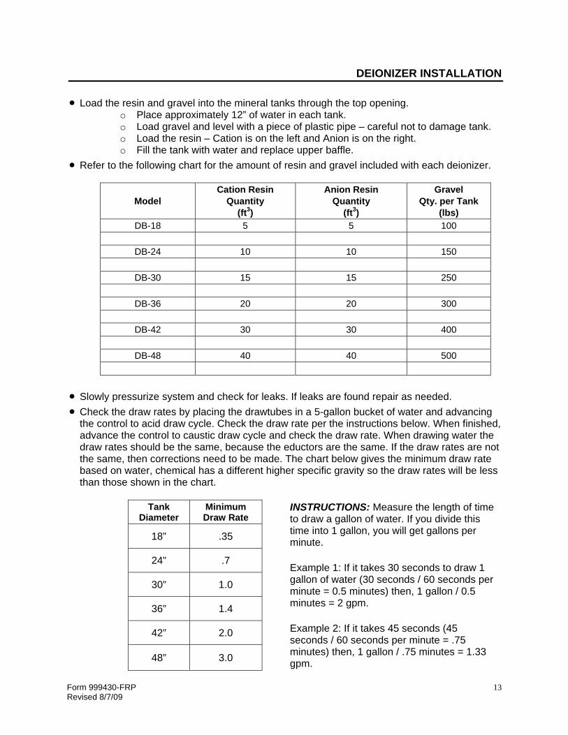
DEIONIZER INSTALLATION • Load the resin and gravel into the mineral tanks through the top opening.
o Place approximately 12” of water in each tank. o Load gravel and level with a piece of plastic pipe – careful not to damage tank. o Load the resin – Cation is on the left and Anion is on the right. o Fill the tank with water and replace upper baffle.
• Refer to the following chart for the amount of resin and gravel included with each deionizer.
Model Cation Resin
Quantity (ft3)
Anion Resin Quantity
(ft3)
Gravel Qty. per Tank
(lbs) DB-18 5 5 100
DB-24 10 10 150
DB-30 15 15 250
DB-36 20 20 300
DB-42 30 30 400
DB-48 40 40 500
• Slowly pressurize system and check for leaks. If leaks are found repair as needed. • Check the draw rates by placing the drawtubes in a 5-gallon bucket of water and advancing
the control to acid draw cycle. Check the draw rate per the instructions below. When finished, advance the control to caustic draw cycle and check the draw rate. When drawing water the draw rates should be the same, because the eductors are the same. If the draw rates are not the same, then corrections need to be made. The chart below gives the minimum draw rate based on water, chemical has a different higher specific gravity so the draw rates will be less than those shown in the chart.
Tank
Diameter Minimum Draw Rate INSTRUCTIONS: Measure the length of time
to draw a gallon of water. If you divide this time into 1 gallon, you will get gallons per minute. Example 1: If it takes 30 seconds to draw 1 gallon of water (30 seconds / 60 seconds per minute = 0.5 minutes) then, 1 gallon / 0.5 minutes = 2 gpm. Example 2: If it takes 45 seconds (45 seconds / 60 seconds per minute = .75 minutes) then, 1 gallon / .75 minutes = 1.33 gpm.
18” .35
24” .7
30” 1.0
36” 1.4
42” 2.0
48” 3.0

Form 999430-FRP Revised 8/7/09
14
DEIONIZER INSTALLATION DEIONIZER TYPICAL INSTALLATION Deionizers produce low Total Dissolved Solids (TDS) water usually in the 20,000 to 50,000 ohm range, which means the water is aggressive and wants to dissolve any material with which it comes in contact. Drain lines, and product lines must be made of corrosion resistant materials, such as PVC, CPVC, or stainless steel. The deionizer has an inlet, an outlet, and three drain lines. It is recommended that manual valves be installed on the inlet and outlet of the system for servicing. The Cation drain will transport waste acid, the Anion drain will transport waste caustic soda, and the Purge drain will transport low quality waste deionized water. Water used during the regeneration process must be neutralized prior to dumping down a standard floor drain. This is governed by local plumbing codes. The drain lines must be ran separately to the neutralization system; do not combine into one pipe. The maximum recommended height for the drain lines is 8 feet above eductor and the minimum height is 3 feet above the eductor. When using a recirculation pump, installation of a check valve on the inlet of the DI is required to prevent deionized water, acid or caustic from being fed into the incoming lines. The recirculation pump comes with a flow meter, check valve, hose and all necessary fittings to install the unit as shown above.

Form 999430-FRP Revised 8/7/09
15
DEIONIZER INSTALLATION SOLID STATE CONTROL PANEL The CQ control is a fully automatic, completely programmable solid-state control for unattended operation of a two-bed Deionizer. The controller has a built-in conductivity meter which constantly monitors water quality, and can initiate a regeneration when quality drops to a pre-set point. The conductivity meter is capable of being set between 0 and 200 uS/cm. The set point selector allows the user to program a minimum quality level. Above the set point an indicator light glows green, while below the set point an indicator light glows orange / yellow. The control will automatically initiate a regeneration when the quality drops below the pre-set limit. Purge
prior to regeneration may be selected as an option on single systems. Regeneration may also be initiated based on pH limit, time, volume of water used, or a combination of these. Two controls may be easily connected together forming a duplex system that automatically removes the exhausted DI train from service, puts the stand-by Deionizer on line, and initiates a regeneration of the exhausted system. The CQ control can be programmed to start a regeneration automatically or to sound an alarm for operator inspection before release of the regeneration sequence. Regeneration of cation and anion vessels can be sequential or simultaneous1. All regeneration timing steps for the cation and the anion are controlled separately from individual switch inputs for flexibility and assured program integrity.
The controls graphic faceplate displays a schematic of the deionizer system for quick operator reference. The display clearly shows whether the deionizer is in service or regeneration, and also shows the regeneration cycles for each vessel. It also provides indicator lights for failsafe valve status, and operation of the optional recirculation pump and regenerant waste holding tank. The control is housed in a plastic corrosion resistant enclosure with sealed electrical connections for maximum reliability. The control comes with a rechargeable battery back up, and operated on low voltage for ease of maintenance and operator safety. A standard 120-volt power source from a 15-amp or 20-amp circuit dedicated to the Deionizer will provide the power required to operation. Black poly tubing is supplied for connecting the diaphragm valves to the 4-way solenoids. A gang-mounted bank of 4-way solenoids pilot operate the diaphragm valves on the system. They are also used to pilot operate air operated Ball Valves or Butterfly Valves on the larger systems. Connect tubing as shown in the “Tubing Diagram”. 1 Simultaneous regeneration requires a softener or lone cation to provide water for the anion column. Consult factory.

Form 999430-FRP Revised 8/7/09
16
DEIONIZER INSTALLATION PNEUMATIC DIAPHRAGM VALVE LOCATION
VALVE SEQUENCE CHART
CYCLE CATION ANION
C1 C3 C4 C5 C6 C7 A1 A2 A3 A4 A5 A6 A7 A8 Service O O O Cation Backwash O O O Acid Draw O O O O Cation Rinse O O O Anion Backwash O O O Caustic Draw O O O O Anion Rinse O O O Quality Purge O O O
O – designates valve is “OPEN”

Form 999430-FRP Revised 8/7/09
17
DEIONIZER INSTALLATION PNEUMATIC TUBING DIAGRAM

Form 999430-FRP Revised 8/7/09
18
REGENERATION CYCLES SERVICE CYCLE The deionizer produces quality water during the Service Cycle. Water flows into the cation tank through the Cation Inlet Valve (C1). The water then passes through the cation resin and the cation exchange takes place. The decationized water flows into the distributors and out the bottom of the tank. The decationized water enters the anion tank through the Anion Inlet Valve (A1). The anions are removed as the water flows down through the anion resin. The deionized water is collected at the bottom of the anion tank and flows out to process through the Failsafe Valve (A2). The recirculation pump is operational during the Service Cycle. If water is not being drawn from the system, the pump will re-circulate the water from the outlet of the Anion to the Inlet of the Cation, and quality will be maintained. If there is no movement of water during periods of no use, the quality will drop causing a pre-mature regeneration to be initiated. Check valves are supplied with the recirculation pumps.

Form 999430-FRP Revised 8/7/09
19
REGENERATION CYCLES CATION BACKWASH CYCLE The Failsafe Valve (A2) is closed preventing water and/or chemical from being accidentally sent to the process. The first regeneration cycle (series regeneration) is the Cation Backwash Cycle. The Cation Inlet Valve (C1) is closed, and the inlet raw water is directed to the bottom of the Cation Column through the Cation Backwash Inlet Valve (C3). The water flows out through the distributors and up through the cation bed providing for at least 50% expansion of the resin. The water then flows out through the top collector to drain through the Cation Backwash Outlet Valve (C4) and the Backwash Flow Control. The Backwash time is usually 10 minutes. It takes approximately 6 of those minutes be fore the resin has reached full expansion. The backwash cycle flushes the particulate matter collected during the service cycle down the drain, and prepares the cation resin for the introduction of the acid regenerant.

Form 999430-FRP Revised 8/7/09
20
REGENERATION CYCLES ACID DRAW CYCLE Valves C3 (Backwash Inlet) and C4 (Backwash Outlet) are now closed. The Cation Eductor Inlet Valve (C6), Rinse Outlet Valve (C5), and the Acid Valve (C7) are opened. Water enters through Valve C6, flows through the eductor, which creates a vacuum and draws the acid through Valve C7 from the chemical container. The mixture of acid and water (normally 6%) is directed to the top of the resin bed. The Acid flows down through the bed removing the Cations collected during Service Cycle. The excess acid and the waste cations exit the Cation Column and flow through Valve C5 to Drain. This drain water is acidic (low pH) and must be neutralized prior to sending it to the city sewage system. The percentage of the acid can be adjusted with use of the metering valve just below Valve C7. Samples of the diluted acid are taken at the test cock above the eductor. The specific gravity of the solution is used to determine the percentage of acid. Refer to the specific gravity chart contained in the Regenerant Specifications section.

Form 999430-FRP Revised 8/7/09
21
REGENERATION CYCLES CATION RINSE CYCLE The Acid Valve (C7) is closed, stopping the flow of acid. The Cation Eductor Inlet Valve (C6) and the Rinse Outlet Valve (C5) remain open allowing water to flow down through the resin rinsing away the excess acid and remaining cations. This water takes the same path as in the previous cycle. The rinse is complete when the pH of the water exiting to drain is between 2.5 and 3.0 and the Hardness is 0 grains. Samples can be taken at the test cock just below the Rinse Outlet Valve (C5). This test cock can also be used to tell when the acid breaks through the bottom of the resin bed. When Rinse is complete, the Cation Column returns to the Service Cycle. Water flows into the Cation Column through Valve C1, and out the bottom over to the Anion Column. The Anion will start the Backwash Cycle.

Form 999430-FRP Revised 8/7/09
22
REGENERATION CYCLES ANION BACKWASH CYCLE The Anion Column uses decationized water for regeneration, and is supplied by the Cation Column. When Simultaneous Regeneration desired, the Anion Column must be supplied with a separate source Soft Water Supply or Decationized Water Supply. The Anion Inlet Valve (A1) is closed and the Backwash Inlet Valve (A3) and the Backwash Outlet Valve (A4) are opened. The decationized water is directed to the bottom of the Anion Column through the Anion Backwash Inlet Valve (A3). The water flows out through the distributors and up through the anion bed providing for at least 50% expansion of the resin. The water then flows out through the top collector to drain through the Anion Backwash Outlet Valve (A4) and the Backwash Flow Control. The Backwash time is usually 10 minutes. It takes approximately 6 of those minutes before the resin has reached full expansion. The backwash cycle flushes the particulate matter collected during the service cycle down the drain, and prepares the anion resin for the introduction of the sodium hydroxide regenerant.

Form 999430-FRP Revised 8/7/09
23
REGENERATION CYCLES CAUSTIC DRAW CYCLE Valves A3 (Backwash Inlet) and A4 (Backwash Outlet) are now closed. The Anion Eductor Inlet Valve (A6), Rinse Outlet Valve (A5), and the Caustic Valve (A7) are opened. Water enters through Valve A6, flows through the eductor, which creates a vacuum and draws the caustic through Valve A7 from the chemical container. The mixture of caustic and water (normally 4 - 6%) is directed to the top of the resin bed. The Caustic flows down through the bed removing the Anions collected during Service Cycle. The excess caustic and the waste anions exit the Anion Column and flow through Valve A5 to Drain. This drain water is caustic (high pH) and must be neutralized prior to sending it to the city sewage system. The percentage of the caustic can be adjusted with use of the metering valve just below Valve A7. Samples of the diluted caustic are taken at the test cock above the eductor. The specific gravity of the solution is used to determine the percentage of caustic. Refer to the specific gravity chart contained in the Regenerant Specifications section. The Anion Resin will also remove hardness from the water, but it can not be regenerated “off” the resin with Sodium Hydroxide (Caustic Soda).

Form 999430-FRP Revised 8/7/09
24
REGENERATION CYCLES ANION RINSE CYCLE The Caustic Valve (A7) is closed, stopping the flow of Sodium Hydroxide. The Anion Eductor Inlet Valve (A6) and the Rinse Outlet Valve (A5) remain open allowing water to flow down through the resin rinsing away the excess caustic and remaining anions. This water takes the same path as in the previous cycle. The rinse is complete when the pH of the water exiting to drain is between 6.8 and 8.1 and the quality starts increasing. Samples can be taken at the test cock just below the Rinse Outlet Valve (A6). This test cock can also be used to tell when the caustic breaks through the bottom of the resin bed. When Rinse is complete, the Anion Column returns to the Service Cycle. Water flows through the Sensor Cell to the Purge Valve (A8).

Form 999430-FRP Revised 8/7/09
25
REGENERATION CYCLES PURGE CYCLE – RINSE to QUALITY The Purge Cycle is the final cycle of regeneration. The Cation Resin has been regenerated with Hydrochloric Acid and the Anion Resin has been regenerated with Sodium Hydroxide. The water coming out of the Cation Column must be between 2.5 and 3.0 ph with 0 Hardness, and the water coming out of the Anion Column should be somewhere between 6.8 and 8.1 pH. The Purge Cycle is used to rinse the Deionizer up to the desired pre-set quality. The Raw Water enters the Cation Column through Valve C1, flows down through the resin and out the bottom of the column as decationized water and into the Anion Column through Valve A1. The decationized water flows down through Anion Resin and out the bottom of the column through the Sensor Cell and out to drain through the Purge Valve (A8). The water running to drain should be low quality deionized water. When the Pre-Set Quality is reached, the Purge Valve (A8) will close and the Failsafe Valve (A2) will open. The Deionizer has returned to the Service Cycle.

Form 999430-FRP Revised 8/7/09
26
CHEMICAL USAGE AND TIME CYCLES REGENERATION TIME CYCLES All the PRO Series Deionizers are designed to have the same time cycles. The times listed are to be used as initial starting times and may need adjusting based on the water pressure, drain length and height, size and length of draw hose and temperature of chemical.
Cation Backwash
Time
Acid Draw Time
Cation Rinse Time
Anion Backwash
Time
Caustic Draw Time
Anion Rinse Time
Purge
10 min. 30 min. 45 min. 10 min. 60 min. 60 min. 10 min.
REGENERATION CHEMICAL REQUIREMENTS The following table is based on regenerating the deionizers with 30% Hydrochloric Acid and diluting it to 6%, and 50% Sodium Hydroxide diluted to 4%.
Deionizer Model
Cation Resin
Quantity
Acid Flow Rate
(gpm)
Gallons of 30%
HCl Required
Anion Resin
Quantity
Caustic Flow Rate
(gpm)
Gallons of 50% Caustic
Required
Eductor
Size Color
DB-18 5 ft3 0.35 10.4 5 ft3 .08 4.7 ¾” Red
DB-24 10 ft3 0.70 21.0 10 ft3 .16 9.4 ¾” White
DB-30 15 ft3 1.05 31.0 15 ft3 .24 14.2 ¾” Blue
DB-36 20 ft3 1.40 42.0 20 ft3 .31 18.9 1” Red
DB-42 30 ft3 2.10 62.0 30 ft3 .48 28.3 1” White
DB-48 40 ft3 2.80 83.0 40 ft3 .62 37.7 1.5” Red
Chemicals may be educted as shown or pumped, but flow rates remain the same. A complete water analysis is required when sizing a two-bed deionizer system. The water analysis is needed to predict the maximum quality of the water and the capacity of the system. The flow rate and the amount of water used must is also required.

Form 999430-FRP Revised 8/7/09
27
CQ CONTROL PROGRAMMING
CQ CONTROL FEATURES
The CQ Control is an automatic solid-state control, which monitors the quality of the product water and can send an alarm signal or initiate a regeneration when quality drops below a preset limit value. The CQ Control provides outputs to control the regeneration cycles of the Cation and Anion Columns as well as the Failsafe Valve, Purge Valve and the Recirculation Pump.
Indicator Lights - The indicator lights lets the operator know what is happening with the deionizer. The green indicator is activated when the system is in the normal service cycle of operation. The red indicator is activated when the deionizer is in a regeneration cycle, or (in the case of a duplex system) stand-by. The quality monitor provides visual indication if the water quality is above or below the set point as well as a digital readout of the quality. See “Conductivity Meter Instructions” for a more detailed explanation of the operation of the monitor.
Manual Regeneration – The Deionizer system can be regenerated at any time with the Manual Regeneration Button no matter what the quality of the water.
Quality Monitor – The water quality monitor is located on the front of the control. It provides a visual check of the water quality being produced by the deionizer.
Battery Back-up – The CQ Control is shipped with a rechargeable 9-volt battery. If a power failure occurs, the battery can maintain memory for up to 20 hours. Should a power outage occur while the deionizer is in the middle of regeneration, the regeneration will continue from where it was interrupted, when power returns. The battery should be installed on the main logic board and the battery clip attached.
Low Voltage – The CQ Control operates on 24-Volts AC, through a power reduction transformer. All the outputs from the CQ Control are low voltage. The transformer has a 120-Volt AC Primary and a 24-Volt AC Secondary.
MODES of OPERATION
The Operating Modes of the Deionizer may be selected during the programming of the CQ Control. Series Regeneration or Parallel Regeneration may be selected by the position of a Toggle Switch. Duplex or Single operation, Regeneration initiated on Quality or from an external contact closure like a Time Clock, Immediate Regeneration or Purge Prior to Regeneration, and Quality Purge or Timed Purge can all be selected with a 4 Position Dip Switch. Both of these switches are located on the Main PC Board. See Picture on next page.

Form 999430-FRP Revised 8/7/09
28
CQ CONTROL PROGRAMMING Toggle Switch – The Toggle provides a way to program the control for Series Regeneration or Parallel Regeneration. If the switch is moved to the “left”, the Cation Column and the Anion Column will advance through the regeneration cycles simultaneously, otherwise called Parallel Regeneration. If the Toggle Switch is moved to the “right”, the Cation Column will regenerate first followed by the Anion Column. This is called Series Regeneration. DO NOT leave the toggle switch in the middle position, it will cause the Deionizer to stop in the middle of regeneration. 4-Position Dip Switch - The Dip Switches are numbered from bottom to top, 1 – 2 – 3 – 4. “ON” is to the left and “OFF” is to the right. The diagram below indicates the operation of the switches. • Switch #1 controls the different options for the Purge Cycle. The Purge Cycle is normally set
for 10 minutes. If Switch #1 is in the “on” position, the Purge Valve (A8) will be open during the Purge Cycle until the quality of water rises above the preset limit. The purge valve will open and close during the purge cycle based on quality. If the quality is below the pre-set limit when the cycle ends, the system will go to Alarm. If Switch #1 is in the “off” position, then the system will purge for the entire time regardless of the quality.
• Switch #2 controls the Purge Prior to Regeneration function, if the system is set-up to
automatically regenerate based on quality. Automatic Regeneration will occur immediately if Switch #2 is in the “on” position. If Switch #2 is in the “off” position, the Purge Cycle will occur for up to 5 minutes prior to regeneration. If the water quality returns during the 5 minutes, the deionizer will return to Service.
• Switch #3 controls the ability to have Automatic Regeneration based on Quality or Semi-
Automatic Regeneration. If the water quality drops below the preset limit, a regeneration is initiated – this is considered an Automatic Regeneration and Switch #3 must be in the “on” position. If Switch #3 is in the “off” position a regeneration can only be started by the Manual Regeneration Button or from an external contact closure. The alarm will be activated, but the deionizer will continue to supply water if the quality drops below the pre-set limit.
• Switch #4 controls whether the System is to be operated as a Duplex or as a Single System.
If Switch #4 is in the “on” position, the system will operate in conjunction with another CQ Control. One Deionizer will be “On-line” while the other is in “Stand-by”. If Switch #4 is “off”, the control will operate as a Single System.
Main PC Board
4-Position Dip Switch
Toggle Switch for Series / Parallel Operation
Rechargeable Battery
4-Position Dip Switch
Duplex SingleQuality Regen Timer Regen
1 Second Delay 5 Minute DelayQuality Purge Timed Purge
ON OFF

Form 999430-FRP Revised 8/7/09
29
CQ CONTROL PROGRAMMING Duplex Wiring - An interconnecting wiring harness is supplied with the CQ Control for Duplex Operation. Two Controls must be connected together in order for the duplex function to work. Connect Terminal #4 in Control ‘A’ to Terminal #6 in Control ‘B’. Connect Terminal #4 in Control ‘B’ to Terminal #6 in Control ‘A’. Connect Terminal #5 in Control ‘A’ to Terminal #5 in Control ‘B’. The Duplex option will not operate correctly with the Purge Prior to Regeneration Option selected, which is Switch #2 of the 4-Position Dip Switch shown on the previous page. Programming the Regeneration Times – The 8-position dipswitches on the front of the control are for setting the regeneration times. Each cycle of regeneration has an 8-position dipswitch associated with it. Each switch has a specific number of minutes it activates, and is capable of being programmed from 1 minute up to 255 minutes. Each switch that is turned “on” adds the minutes associated with it to the other switches. Example: Turn “on” switch #2 and switch #4. A total of 10 minutes will be set (2 minutes + 8 minutes). If switch #6 and switch #4 are turned “on”, 40 minutes are programmed (32 minutes + 8 minutes). Refer to the diagram at the right. There are 8 dipswitches on the front of the CQ Control, each dipswitch times a different cycle of regeneration. In order to make things as simple as possible, the eductors and flow rates have been set up so that the time settings for the cycles are the same no matter what size the system. The chart below shows the initial times for each cycle and the switches that need to be turned “on” to achieve these time settings.
Model Regeneration Cycle
Time Setting
Dipswitches “on” 1 2 3 4 5 6 7 8
All
Cation Backwash 10 min. X X
Acid Draw 30 min. X X X X
Cation Rinse 45 min. X X X X
Auxiliary 0 min.
Anion Backwash 10 min. X X
Caustic Draw 60 min. X X X X
Anion Rinse 60 min. X X X X
Purge 10 min. X X Note: Time settings in chart are starting points. Actual amount of chemical and percentage along with water pressure will dictate actual times required.
1 Minute 2 Minutes 4 Minutes 8 Minutes 16 Minutes 32 Minutes 64 Minutes128 Minutes

Form 999430-FRP Revised 8/7/09
30
CQ CONTROL WIRING CONNECTIONS
* Field Wiring Connections ***
* * *

Form 999430-FRP Revised 8/7/09
31
CONDUCTIVITY METER INSTRUCTIONS General Description - The Conductivity Meter utilized in the CQ Control is model BL983320-1 (120 / 230 volt version) Conductivity Monitor by Hanna Instruments. The Monitor is equipped with a set of Alarm or Dosing contacts. These contacts close when the conductivity drops below the preset value. The preset value should be somewhere between 10 uS (100,000 ohms) and 100 uS (10,000 ohms), usually 20 uS (50,000 ohms). The chart below provides the conversion between ohms and uS. Connections and wiring are made via terminal strips on the rear panel. The Probe is easy to clean and requires little maintenance. Other features include automatic temperature compensation of readings, single point calibration, multi-color LED for indicating if the meter is in measurement / dosing / alarm condition, possibility to (Off-Auto-On switch) alarm action mode. Conversion Table Functional Description – Front Panel
1. Liquid Crystal Display 2. Switch for selecting Alarm Mode
• OFF = alarm disabled • Auto = automatic alarm based on set
point value • ON = alarm always active
3. “MEAS” - push button to set instrument to measurement mode.
4. “SET” - push button to display and set the set-point value.
5. “SET” – trimmer pot to adjust set-point value.
6. “CAL” – calibration trimmer pot. 7. 3 – Color LED indictor
• Green = meter in measurement mode • Orange / Yellow = alarm activated • Red Blinking = error condition
Resistivity OHMS
Conductivity US /cm
Total Dissolved Solids ppm
Grains per Gallon
100,000 10 5 .29 62,500 16 8 .46 50,000 20 10 .58 25,000 40 20 1.16 10,000 100 50 2.9

Form 999430-FRP Revised 8/7/09
32
CONDUCTIVITY METER INSTRUCTIONS Functional Description – Rear Panel
Set-point Adjustment – Turn on the Power and press the “SET” button; the display will show the default of previously adjusted value, along with the “SET” indicator. Use a small screwdriver to adjust the “SET” trimmer pot until the desired set-point value is displayed. The instrument will automatically returns to the normal measurement mode after 1 minute, or if the “MEAS” button is pushed. Testing the Meter Operation – Turn on the control and adjust the set point to 20 uS/cm (50,000 ohms). Make sure the #5 jumper has been removed from the rear of the monitor. Turn the “Off/Auto/On” switch to the “Auto” position. Immerse the probe in the solution to be monitored, and press the “MEAS” button (if necessary). The LCD will show the uS/cm value of the liquid. The LED indicator will light up Green when the meter is in measurement mode and #3 “Dosing contact” is open, but will light up Orange/Yellow when #3 “Dosing contact” is closed. A regeneration will be initiated when the contact is closed. To prevent this – temporarily remove one of the wires on the #3 “Dosing contact” terminals. Calibration – The meter should be in the measure mode. Immerse the probe in the calibration solution HI 7033 (this solution is 84.0 uS/cm). Shake briefly and wait for reading to stabilize. Adjust the “CAL” trimmer pot to read “84.0 uS” on the LCD display. Note: The meter was calibrated at the factory prior to shipment. Probe Maintenance – To prolong the life of the probe, it is recommended that it be cleaned regularly. Immerse the tip of the probe in HI 7061 Cleaning Solution at least for 1 hour. If a more thorough cleaning is desired, lightly sand the metal pins with very fine sand paper. After cleaning, rinse the probe with tap water and recalibrate the meter. When not is use, the probe should be cleaned prior to storage.
1. Connections for Conductivity Cell 2. Power Supply Terminal Strip 3. Alarm or Dosing contact – closes on bad quality. 4. Not Used 5. Jumper for disabling the overtime control. To
disable, simply remove the jumper. See 6 for detailed explanation of overtime control.
6. Trimmer pot for adjusting overtime control. The allows the user to set the maximum period the alarm or dosing contact is closed, from a minimum time of 5 minutes to a maximum of 30 minutes. When the set time is exceeded, the contacts open, the LED indicator on the front panel will blink Red and the LCD will show “TIMEOUT”. To exit this condition the “OFF/Auto/ON” switch must be turned ‘Off” and then back to “Auto”. The Jumper should be removed for use with all DI Systems.

Form 999430-FRP Revised 8/7/09
33
TECHNICAL DATA OPERATING CHECK LIST The following information is essential when trouble shooting the deionizer. Take a sample of each regenerant and label. Retain all samples for which labeling is requested below. Follow the instructions and fill-in the required data. 1) Push the regeneration button and record the time. ___________ 2) Record rate of flow to drain during cation backwash. ________gpm 3) Record inlet pressure during cation backwash cycle. _________psi 4) Record time at start of acid draw. ___________ 5) Record rate of flow to drain when acid draw begins. ________gpm 6) Take a sample of the drain effluent 5 minutes after the start of acid draw. Keep the sample and label it 5C. Record the specific gravity (Sp. G.) ___________ 7) Record the specific gravity after 10 minutes, and label 10C. ___________ 8) Record the specific gravity after 20 minutes, and label 20C ___________ 9) Record the specific gravity after 30 minutes, and label 30C ___________ 10) Record the specific gravity after 40 minutes, and label 40C ___________ 11) Record time when acid draw stops and rinse begins. ___________ 12) Record rate of flow to drain during slow rinse. ________gpm 13) Record pressure during acid draw and rinse cycles. _________psi 14) Record time when anion backwash starts. ___________ 15) Record flow rate to drain during anion backwash. ________gpm 16) Record inlet pressure during anion backwash. _________psi 17) Record time at start of caustic draw. ___________ 18) Record rate of flow to drain at start of caustic draw. ________gpm 19) Take a sample of the drain effluent 5 minutes after the start of caustic draw. Keep the sample and label it 5A. Record the specific gravity (Sp. G.) ___________ 20) Record the specific gravity after 10 minutes, and label 10A. ___________ 21) Record the specific gravity after 20 minutes, and label 20A. ___________ 22) Record the specific gravity after 30 minutes, and label 30A. ___________ 23) Record the specific gravity after 40 minutes, and label 40A. ___________ 24) Record time when caustic draw stops and rinse begins. ___________ 25) Record rate of flow to drain during slow rinse. ________gpm 26) Record pressure during caustic draw and rinse cycles. _________psi 27) Record time when Purge (Quality Rinse) starts. ___________ 27) Record specific resistivity or conductivity after Purge cycle. ___________ 28) Take a sample of the deionized water once quality is reached. Label the sample. 29) Record maximum quality obtained. ___________ 30) Record pH of quality deionized water. ________pH Take a raw water sample and obtain an analysis of the raw water (16 ounce sample required). If necessary, collect two 16 oz samples of cation effluent water and two 16 oz samples of anion effluent water.

Form 999430-FRP Revised 8/7/09
34
TECHNICAL DATA MEANING of PH The pH is used to measure the acidic or alkaline level of a solution. High pH denotes a more alkaline solution. Low pH denotes an acidic solution. The pH is actually the measure of hydrogen ion concentration in water, and equals the ratio of Bicarbonate Alkalinity to Free Carbon Dioxide. All natural waters fall within a pH of 6.0 to 8.0. A pH of 7.0 is considered to be neutral.
pH 0 1 2 3 4 5 6 7 8 9 10 11 12 13 14
Acidic Neutral Basic QUALITY of WATER (CONDUCTIVITY or RESISTIVITY) Ions in the water conduct electricity. Electric current flows easier with high concentrations of ions than it does with low concentrations. High quality water is low in ion concentration therefore, has a high resistance to electric current. The measurement of electrical conductivity or resistivity provides an accurate measurement of ionic concentration in the water.
Sodium Chloride (mg/l)
TDS - mg/l (as CaCO3)
Conductivity (µS/cm)
Resistivity (ohms)
TDS Grains/gal (as CaCO3)
0.024 0.020 0.050 20,000,000 0.0011 0.026 0.022 0.055 18,000,000 0.0012 0.033 0.028 0.07 14,000,000 0.0016 0.039 0.033 0.08 12,000,000 0.0019 0.047 0.04 0.1 10,000,000 0.0023 0.094 0.08 0.2 5,000,000 0.0047 0.235 0.20 0.5 2,000,000 0.0116 0.47 0.40 1.0 1,000,000 0.0233 0.63 0.53 1.3 750,000 0.030 0.94 0.8 2 500,000 0.046 2.35 2.0 5 200,000 0.117 4.70 4.0 10 100,000 0.234 9.41 8.0 20 50,000 0.467 23.5 20 50 20,000 1.17 47.0 40 100 10,000 2.34 94.1 80 200 5,000 4.68 470 400 1,000 1,000 23.4 941 800 2,000 500 46.8

Form 999430-FRP Revised 8/7/09
35
TECHNICAL DATA TESTING HARDNESS of DECATIONIZED WATER Decationized water is acidic and must be neutralized before an accurate hardness test can be performed. Draw a pint of decationized water from the cation outlet test cock. Use an eyedropper and add 1 drop of caustic soda at a time until a pH of 7.0 is reached. Take small samples from the pint to perform the pH test. Do not use pH chemicals or litmus paper in the pint sample, they will contaminate the sample and the reading will not be accurate. Once the pH is corrected, a sample can be removed from the pint and the hardness test ran. Follow the instructions supplied with the hardness test kit. DOUBLE REGENERATING the CATION RESIN The primary cause of hardness leakage or premature sodium leakage from the Cation column is lack of regenerant. This may be due to low water pressure, obstructed eductor, blocked draw tubing, or low level of acid in the chemical container. First determine the cause for low acid usage and correct it. Once the problem is corrected, the resin can be restored to peak capacity by overdosing with acid.
• Reset the acid draw time to double the normal time. • Initiate a regeneration and allow system to advance through regeneration
normally. This will draw twice the amount of acid and allow twice the normal contact time. The decationized water after regeneration should be between 2.5 and 3.0 pH and 0.0 hardness. If the cation has leaked hardness to the anion column, it must also be acidized. REMOVAL of HARDNESS from the ANION RESIN Leakage of hardness from the Cation column can foul the Anion resin. If poor quality is experienced from the Deionizer, check the hardness of the decationized water. This may be the cause for poor quality. Other causes may be attributed to the lack of Sodium Hydroxide (Caustic Soda) such as low water pressure, obstructed eductor or draw tube, or low chemical. The hardness can be removed from the Anion resin by regenerating it with Acid. The following procedures should be followed to accomplish this.
• Connect the Acid draw hose to the Anion Eductor and initiate a regeneration of the Anion Column.
• Drawing acid into the Anion column, which contains sodium hydroxide will cause the release of carbon dioxide. Do not stop the regeneration in the middle of the cycle, the CO2 must be allowed to escape! Some heat may also be noticed and gurgling sounds from inside the tank, this is normal.
• Allow the Anion to continue through regeneration. When rinse is complete advance the system to service. Reconnect the acid draw hose to the Cation column and reconnect the caustic draw hose to the Anion column.
• Initiate a normal regeneration. Monitor the acid and caustic to insure proper amounts of chemical are used for regeneration.

Form 999430-FRP Revised 8/7/09
36
TECHNICAL DATA The length of time necessary to restore the anion resin’s performance depends on the degree of fouling. It may be necessary to allow the unit to sit overnight with the acid in it. Follow the steps below to accomplish this.
• Connect the drawtubes as previously described. After the acid is drawn, allow the Anion column to rinse for 2 minutes, then turn off the water and remove the fill plug from the top of the tank. Venting the tank in this manner will allow the CO2 to escape while the system is sitting.
• Turn “off” the control and allow the system to sit over night. A minimum of 8 hours is recommended.
• Connect the drawtubes back to their proper positions. The acid should be connected to the Cation column and the caustic soda should be connected to the Anion column.
• Replace the fill plug and slowly pressurize the system. Turn “on” the control panel and advance the anion column into the rinse cycle. Rinse the anion column for 60 minutes.
• Advance the control to the beginning of the regeneration cycle (Cation Backwash) and allow the system to regenerate normally.
After the regeneration, if the quality fails to return, the resin may be beyond salvage or it may be past it’s normal service life of 3 to 5 years. In either case, the resin should be replaced. A sample of the resin may be sent to the resin manufacturer for analysis, but there is a fee involved with this, usually $100 or more. REMOVAL of ORGANICS from the ANION RESIN The need to clean the Anion resin bed of organic fouling will most often recognized by long rinses required to achieve quality after regeneration. If it is determined that the resin is organically fouled, a brine solution may be used to remove the organics from the Anion resin. Follow the steps below to brine the Anion column.
• Mix a solution of 9 parts sodium chloride to 1 part sodium hydroxide. Five gallons of this solution is required for each cubic foot of Anion resin. Example – 10 ft3 of anion resin requires 50 gallons of solution. Note: This ratio can be achieved by dissolving 3.75 lbs of salt and 7 oz. of 50% liquid caustic soda in 5 gallons of water.
• Connect tubing from the salt/caustic solution to the anion eductor. • Initiate a regeneration of the Anion column. Allow the Anion to complete the
regeneration through the rinse cycle, then advance the control to the service position.
• Reconnect the normal caustic drawtube to the eductor and then regenerate the entire system.
If quality fails to return at the end of the normal regeneration, the resin may be beyond salvage or it may be past its normal service life of 3 to 5 years. In either case, the resin should be replaced. A sample of the resin may be sent to Ecodyne Industrial for analysis, but there is a fee for this service.

Form 999430-FRP Revised 8/7/09
37
REGENERANT SPECIFICATIONS REGENERANT SPECIFICATIONS for HYDROCHLORIC (MURIATIC) ACID*
CHEMICAL 18° BAUME 20° BAUME 22° BAUME SPECIFICATION TECHNICAL TECHNICAL TECHNICAL
Strength (% HCl) 27.92% 31.45% 35.21% Sp. Gr. 1.1417 1.1600 1.1789 Wt. Per Gallon 9.5# 9.66# 9.81# Color Yellow Yellow Yellow Sulfate as (H2SO4) 0.003% max. 0.003% max. 0.003% max. Sulfite 0.0005% max. 0.0005% max. 0.0005% max. Calcium 0.0001% max. 0.0001% max. 0.0001% max. Arsenic 0.1 ppm max. 0.1 ppm max. 0.1 ppm max. Lead 0.0001% max. 0.0001% max. 0.0001% max. Copper 0.0001% max. 0.0001% max. 0.0001% max. Iron 0.0005% max. 0.0005% max. 0.0005% max. Organics 0.0010% max. 0.0010% max. 0.0010% max. Chlorine 10 ppm 10 ppm 10 ppm Fluorine 0.0001% max. 0.0001% max. 0.0001% max.
CAUTION! ALWAYS ADD ACID TO WATER, NEVER IN THE REVERSE ORDER. WHEN HANDLING ACID, WEAR PROTECTIVE CLOTHING AND FACE MASK. Hydrochloric acid and its fumes are highly corrosive and can cause severe burns on contact with any part of the body. Mucous membranes of the eyes and the upper respiratory tract are especially susceptible to high atmospheric concentrations. NEVER inhale fumes given off by hydrochloric acid and provide adequate ventilation where the acid is being used. Hydrochloric acid will dissolve many metals and cements. It will not react with glass, some rubber, and most plastics. All contact with body or clothing should be avoided. Safety goggles or face shield should be used. If hydrochloric acid does contact the body or clothing, the affected clothing should be removed and large quantities of cold water applied. It is usually not necessary to neutralize the acid, but washing with a mild soap will aid removal. Soda ash, washing soda, salt soda or even baking soda and bicarbonate of soda also can be used on large amounts of spilled acid. If hydrochloric acid splashes on the body, flush with water. Then a solution or paste of baking soda can be used to neutralize the acid. If hydrochloric acid splashes in the eyes, flush with water for 10-15 minutes. Call a doctor at once.
% HCl Specific Gravity Baume’ Lbs. of HCL per Gallon
of Solution Total Wgt. of Solution
in Lbs. per Gallon 1 1.0032 0.5 0.083 8.359 2 1.0082 1.2 0.168 8.401 4 1.0181 2.6 0.339 8.484 6 1.0279 3.9 0.515 8.566 8 1.0376 5.3 0.693 8.647 10 1.0474 6.6 0.874 8.728 12 1.0574 7.9 1.059 8.812 16 1.0776 10.4 1.439 8.979 20 1.0980 12.9 1.833 8.149 30 1.1492 18.8 2.877 8.577

Form 999430-FRP Revised 8/7/09
38
REGENERANT SPECIFICATIONS REGENERANT SPECIFICATIONS for SODIUM HYDROXIDE (CAUSTIC)
CHEMICAL SPECIFICATION
50% LIQUID FLAKE OR PELLETS
RAYON GRADE MERCURY CELL
GRADE RAYON GRADE
Strength (% NaOH) 49.0-51% 49.0-51.01 98.5% Sp. Gr. 1.5253 1.5253 Wt. Per Gallon 12.75# 12.75# Sodium Oxide (Na2O) 39.0-39.5% 38.0-39.5% 76.3% Sodium Carbonate (Na2CO3) 0.05% max. 0.20% max. 0.70% max. Sodium Chloride (NaCl) 0.005% max. 0.10% max. 0.25% max. Sodium Sulfate (Na2SO) 0.0001% max. 0.20% max. 0.10% max. Sodium Chlorate (NaCIO3) 0.0001% max. 0.0005% max. None Silicon (Si) 0.0005% max. 0.010% max. 0.02% max. Iron (Fe) 0.0003% max. 0.0005% max. 0.0025%max. Calcium (Ca) 0.0005% max. 0.0007% max. 0.0015% max. Magnesium (Mg) 0.0020% max. 0.0020% max. 0.002% max. Aluminum (Al) 0.0003% max. 0.0003% max. 0.001% max. Manganese (Mn) 0.00001% max 0.0002% max. 0.0005% max. Copper (Cu) 0.00003% max 0.0007% max. 0.0001% max. Nickel (Ni) 0.00003% max 0.0007% max. 0.0002% max.
“CAUTION! WHEN HANDLING CAUSTIC SODA ALWAYS WEAR PROTECTIVE CLOTHING AND FACE SHIELD OR SAFETY GOGGLES. Caustic soda is a strong alkali, which can cause serious burns on contact with skin or eyes. Caustic dust and mist represent a hazard to the respiratory tract. All contact with body or clothing should be avoided. If caustic soda does contact the body or clothing, the affected clothing should be removed and washed with large quantities of cold water. Caustic destroys wool and leather ‘ so these materials should be avoided. If caustic soda splashes on the body, flush with large quantities of water. DO NOT ATTEMPT CHEMICAL NEUTRALIZATION. If caustic soda splashes into the eyes, wash from the eyes with a steady, gentle stream of water for 15 minutes. Do not use soap. Call a doctor at once.
% NaOH Specific Gravity Baume’ Lbs. of NaOH per gallon of Solution
Total Weight of Solution in Lbs. per Gallon
1 1.0095 1.4 0.084 8.412 2 1.0207 2.9 0.170 8.506 3 1.0318 4.5 0.258 8.598 4 1.0428 6.0 0.348 8.690 5 1.0538 7.4 0.439 8.782 6 1.0648 8.8 0.533 8.873 8 1.0869 11.6 0.726 9.057 10 1.1089 14.2 0.925 9.241 12 1.1309 16.8 1.333 9.424 20 1.2191 26.1 2.035 10.159 30 1.3320 36.2 3.333 11.100 50 1.5253 49.9 6.365 12.711
NOTE: One Gallon of Water = 8.333 pounds.

Form 999430-FRP Revised 8/7/09
39
REGENERANT SPECIFICATIONS CONVERSION CHART The chart shown below converts inches to gallons of chemical removed during regeneration from a 50-gallon drum or 15 gallon carboy.
CHEMICAL USAGE CONVERSION CHART
INCHES 50 GAL. DRUM 15 GAL. CARBOY
.25 .4125 Gal. .1435 Gal. .5 .825 Gal. 287 Gal.
.75 1.2375 Gal. .4305 Gal. 1. 1.65 Gal. .574 Gal. 2. 3.3 Gal. 1.148 Gal. 3. 4.95 Gal. 1.722 Gal. 4. 6.6 Gal. 2.296 Gal. 5. 8.25 Gal. 2.87 Gal. 6. 9.9 Gal. 3.444 Gal. 7. 11.55 Gal. 4.018 Gal. 8. 13.2 Gal. 4.592 Gal. 9. 14.85 Gal. 5.166 Gal.
10. 16.5 Gal. 5.74 Gal. 11. 18.15 Gal. 6.314 Gal. 12. 19.8 Gal. 6.888 Gal. 13. 21.45 Gal. 7.462 Gal. 14. 23.1 Gal. 8.036 Gal. 15. 24.75 Gal. 8.61 Gal. 16. 26.4 Gal. 9.184 Gal. 17. 28.05 Gal. 9.758 Gal. 18. 29.7 Gal. 10.332 Gal. 19. 31.35 Gal. 10.906 Gal. 20. 33.Gal. 11.48 Gal.
50 GALLON DRUM: 1” = 1.65 GALLON 15 GALLON CARBOY: 1” = .375 GALLON
Note: Measurements are to be made prior to and after regeneration. Measurements are to be taken from the lip of the container opening down to the chemical. Subtract the prior to regeneration measurement from the after measurement to obtain the inches of chemical used. Inches of chemical used can then be converted to gallons using the chart above.

Form 999430-FRP Revised 8/7/09
40
REGENERANT SPECIFICATIONS QUANTITY OF REGENERANTS PROGRAMMED TO BE USED FOR EACH REGENERATION. (SEE “OPERATOR DATA”) ACID: ______________ INCHES. CAUSTIC: ________________ INCHES. REGENERANT CONTAINER 15 GAL. CARBOY: ______________ 50 GAL. DRUM:______________ MEASUREMENT OF INCHES FROM CONTAINER OPENING DOWN TO REGENERANT, NOTED PRIOR TO EACH REGENERATION.
INCHES DAY
START OF FULL REGENERANT ACID CAUSTIC CONTAINER ENTRY MADE BY
1 2 3 4 5 6 7 8 9 10 11 12 13 14 15 16 17 18 19 20 21 22 23 24 25 26 27 28 29 30 31
The availability and usage of acid and caustic soda during regeneration is one of the most important factors affecting the Deionizer’s performance. Exhaustion of either chemical will cause the deionizer to produce a lower quality of treated water than desired.

Form 999430-FRP Revised 8/7/09
41
MAJOR PARTS and REBUILD KITS PLUMBING PARTS * See Page 43 for tank Internals

Form 999430-FRP Revised 8/7/09
42
MAJOR PARTS and REBUILD KITS PLUMBING PARTS - Continued
ITEM NO. DESCRIPTION PS / PW Deionizer Size
21” 24” 30” 36” 42” 48”1 Fiberglass Tank 403139 403140 403138 403141 403132 403133
2 Diaphragm Valve - NO 211040 51925 51925 51925 211007 211007
3 Female Solvent Weld Adapter - 5258 5258 5258 - -
4 Male Solvent Weld Adapter - 5191 5191 5191 219015 219015
5 O-Ring for Adapter - 5257 5257 5257 508004 508004
6 Diaphragm Valve – NO 211040 211023 211023 211023 51925 51925
7 Valve Retainer & Nut Kit 702044 702044 702044 702044 211031 211031
8 Diaphragm Valve – NC/SC/LS 211005 211005 211005 211005 52713 52713
9 Diaphragm Valve – NO/SC Isolated Bonnet for Caustic 211071 211071 211071 211071 211071 211071
10 Diaphragm Valve – NO/SC Isolated Bonnet for Acid 211072 211072 211072 211072 211072 211072
11 Diaphragm Valve – NO/LS 211038 211004 211004 211004 211001 211001
12 Cation - Backwash Flow Control - PVC
204118 1”–10 gpm
204033 1”-15 gpm
204034 1”-20 gpm
204035 1.5”-30 gpm
204120 1.5”-40 gpm
204122 2”-50 gpm
13 Anion - Backwash Flow Control - PVC
604003 3/4”–5 gpm
204117 1”-7 gpm
204118 1”-10 gpm
204033 1.5”-15 gpm
204119 1.5”-20 gpm
204121 1.5”-25 gpm
14 Chemical Metering Valve 212066 212066 212066 212066 212066 212066
15 Ball Check Valve – Viton for Acid 212025 212025 212025 212025 212025 212025
16 Ball Check Valve – EPDM for Caustic 212008 212008 212008 212008 212008 212008
17 Conductivity Sensor Cell 118039 118039 118039 118039 118039 118039
18 Sample Valve 233011 233011 233011 233011 233011 233011
19 Upper Distributor Assembly 296180 296180 296180 296180 298087 298087
20 20A 20B
Lower Distributor Assembly Hub (only) Lateral (only) (8-req’d)
296196 - -
296196 - -
296195 - -
296178 - -
- 298154 298071
- 298154 298072
21* Draw Tube Assembly 908009 908009 908009 908009 908009 908009
22* 1/8” NPT x 1/4” Tube Fitting 6144 6144 6144 6144 6144 6144
23* 1/4” NPT X 1/4” Tube Fitting 6145 6145 6145 6145 6145 6145
24* 1/4” Tube Tee Fitting 6149 6149 6149 6149 6149 6149
25* 1/4” Poly Tubing 4887 4887 4887 4887 4887 4887
* Items not shown.

Form 999430-FRP Revised 8/7/09
43
MAJOR PARTS and REBUILD KITS PLUMBING PARTS - (continued) Upper and Lower Distributor Assemblies PLASTIC DIAPHRAGM VALVE REBUILD KITS
Valve Size Description Valve
Part No. Diaphragm & Seal Kit
1” 521 NO / SC / LS 211005 56063-02
1” 521 NC / SC 51927 56063-02
1” 521 NO / SAO 211040 56063-02
1” 521 NO / SC 51928 56063-02
1” 521 NO / SAO / LS 211038 56063-02
1” 521 NO 211023 56063-02
1” 5521 Bonnet - Caustic 211071 56063-02
1” 5521 Bonnet - Acid 211072 56063-02
1.5” / 2” 524 NO / SC 211006 56063
1.5” / 2” 524 NC / SC 211052 56063
1.5” / 2” 524 NO-No Spring 51925 56063
1.5” / 2” 524 NC / SC / LS 52713 56063
1.5” / 2” 524 NO-25lb Spring 211002 56063
1.5” / 2” 524 NO / LS 211004 56063
2.5” / 3” 526 NO 211007 56063-03
2.5” / 3” 526 NO / SC 211001 56063-03
2.5” / 3” 526 NO / SO 211003 56063-03
Normally Open Valve
Normally Closed Valve
Hole in Shaft

Form 999430-FRP Revised 8/7/09
44
MAJOR PARTS and REBUILD KITS CONTROL PANEL
ITEM NO. DESCRIPTION PART NO. QTY. REQ’D
1 Black Face Plate 120054 1 2 Regeneration Timer PC Board 120049 2 3 LED PC Board 120047 1 4 PC Mother Board 120048 1 5 Rechargeable Battery 15144 1 6 3 Amp Fuse 105018-3 1 7 Midget Relay – 4 Pole Double Throw – 24 VAC 103013-4 4 8 Midget Relay – 1 Pole Double Throw – 24 VAC 103013-1 2 9 Transformer – 120 / 240 VAC X 24VAC / 50VA 106010 1 10 Two Position Rotary Switch 110002 1 11 Momentary Push Button Switch 110001 1 12 Resistivity Monitor 118038 1 13 Light Bulb – 24 VAC 102017 2 14 Lamp Assembly 102015 2 15 Green Lens Cap 102016 1 16 Red Lens Cap 102018 1

Form 999430-FRP Revised 8/7/09
45
MAJOR PARTS and REBUILD KITS CONTROL PANEL
Form 999430-FRP Revised 8/7/09
46
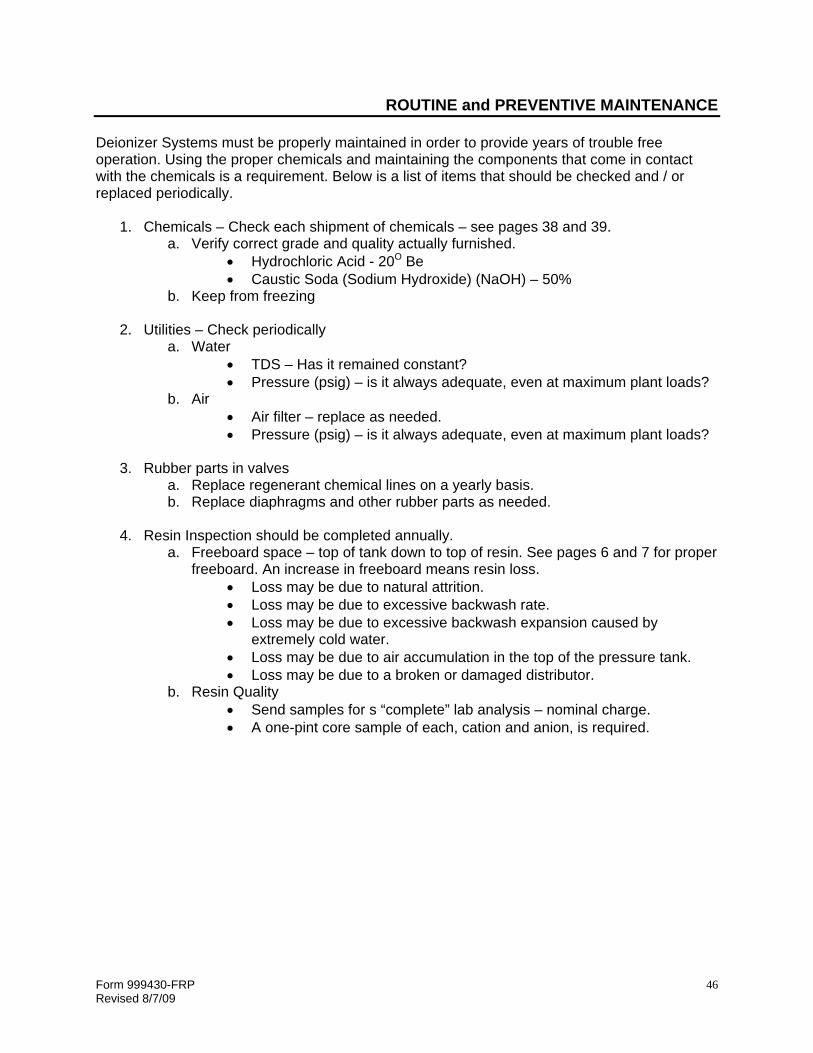
ROUTINE and PREVENTIVE MAINTENANCE Deionizer Systems must be properly maintained in order to provide years of trouble free operation. Using the proper chemicals and maintaining the components that come in contact with the chemicals is a requirement. Below is a list of items that should be checked and / or replaced periodically.
1. Chemicals – Check each shipment of chemicals – see pages 38 and 39. a. Verify correct grade and quality actually furnished.
• Hydrochloric Acid - 20O Be • Caustic Soda (Sodium Hydroxide) (NaOH) – 50%
b. Keep from freezing
2. Utilities – Check periodically a. Water
• TDS – Has it remained constant? • Pressure (psig) – is it always adequate, even at maximum plant loads?
b. Air • Air filter – replace as needed. • Pressure (psig) – is it always adequate, even at maximum plant loads?
3. Rubber parts in valves
a. Replace regenerant chemical lines on a yearly basis. b. Replace diaphragms and other rubber parts as needed.
4. Resin Inspection should be completed annually.
a. Freeboard space – top of tank down to top of resin. See pages 6 and 7 for proper freeboard. An increase in freeboard means resin loss.
• Loss may be due to natural attrition. • Loss may be due to excessive backwash rate. • Loss may be due to excessive backwash expansion caused by
extremely cold water. • Loss may be due to air accumulation in the top of the pressure tank. • Loss may be due to a broken or damaged distributor.
b. Resin Quality • Send samples for s “complete” lab analysis – nominal charge. • A one-pint core sample of each, cation and anion, is required.

Form 999430-FRP Revised 8/7/09
47
TROUBLESHOOTING GUIDE
PROBLEM CAUSE SOLUTION Low Water Quality
A. Monitor or Cell Malfunction. B. Lower grade chemicals
cause resin fouling. C. Commercial grade caustic
will foul anion resin within 2 to 3 regenerations.
D. Inhibited muriatic acid will foul cation resin.
E. Regeneration temperature too low – below 50O F.
F. Insufficient amount of acid and /or caustic used.
G. Percentage of acid and/or caustic too low.
H. Inadequate regeneration time.
I. Incorrect service flow rates.
J. Organic fouling of anion strong base resin.
K. Hardness fouling of anion strong base resin.
A. Check performance and replace. B. Verify that the acid and caustic used
meets required specifications. C. Change caustic soda to proper type
and percentage.
D. Change acid to commercial grade 20O Be.
E. Use a blending valve to increase water temperature.
F. Determine actual amount of chemical used, and increase time as required.
G. Check inlet water pressure. Low pressure will cause low flow rates, and high pressure will cause high flow rates.
H. Short time cycles will not allow enough chemical. Adjust times accordingly.
I. High flow rates do not allow enough contact time with resin. Slow down service flow rate. Low flow rates cause channeling. Use recirculation pump.
J. Clean up anion resin. See “Removal of Organics for Anion Resin” – page 37.
K. Clean up anion resin. See “Removal of Hardness from Anion Resin” – page 36.
Low Capacity
A. Change in supply. Increase
in TDS reduces gallonage throughput.
B. Increase in water usage.
A. Get updated water analysis and
recalculate gallons between regenerations.
B. Re-evaluate actual water usage using a water meter.
Will Not Draw Chemical – Acid or Caustic
A. Water Pressure too low. B. Rate set valves in chemical
line closed. C. Worn or wrong eductor. D. Back Pressure on down-
stream side of eductor or from restricted drain line.
E. Overhead drain too high, causing backpressure on eductor system.
F. Caustic soda too cold will not flow through tubing.
G. Solenoid Coil burned out.
A. Correct water pressure problem. B. Adjust valves to obtain proper amount
of chemical draw. C. Change eductor. D. Find and remove the restriction –
usually resin or other foreign matter in drain line.
E. Reduce height of drain line – maximum height is 8 feet above eductor.
F. Add heat belt to drum – caustic must be above 65O F preferably 90O F.
G. Check coil with ohmmeter – if not resistance coil should be replaced.

Form 999430-FRP Revised 8/7/09
48
OPTIONS and ACCESSORIES
VACUUM PROTECTION (OPTIONAL) Caution: Do not subject the fiberglass deionizer tanks to an internal vacuum - they may be damaged. Using a siphon break to vent the drain can eliminate drain line suction. If the service line is subject to a vacuum (such as a pump down stream), install vacuum breakers on the lower harness crosses of both tanks. Each cross has a plug that can be removed to provide a connection point for the vacuum breaker. RECIRCULATION PUMP SYSTEM (OPTIONAL) Recirculation pumps are available for all of our deionizer systems. The purpose of the recirculation system is to maintain a minimum flow rate through the resin bed during no flow or low flow service requirements. During these periods, the water quality tends to deteriorate, or channeling may occur. The recirculation system draws water from the deionizer product side and pumps it back into the inlet side thereby keeping the flow rate high enough to prevent channeling of the resin bed and subsequent loss of quality or capacity. The pump is turned OFF regeneration and is turned on during Service. The pump will automatically recirculate the deionized water when the differential pressure across the bed drops below the head pressure of the pump. Usage of water to service causes the pump to stop pumping. The pump is a low head, low flow design constructed of stainless steel. The pump system come complete with 2 - check valves (one for the pump discharge and one for the service inlet), a flow meter, and all the fittings and hose for proper installation. Recirculation pumps are required on Duplex Systems to maintain quality when the system is in stand-by. ALTERNATE WATER SOURCE KITS (OPTIONAL) Alternate Water Source Kits are utilized when the process water is different from the regeneration water. An example of this would be when the deionizer is providing water for a recirculated rinse application, and the regenerant water to be used is a normal city water source. The kits come complete with diaphragm valves, solenoid valves, tubing and installation instructions. SKID MOUNTING and ASSEMBLY (OPTIONAL) The deionizer systems are available skid mounted and pre-assembled for ease in installation. The complete deionizer including a recirculation pump, if required, can be factory mounted on a steel skid, pre-piped, the control panel installed and the pneumatic tubing connected to the diaphragm valves. Resin and gravel must be shipped separately. Duplex 36” and smaller deionizer systems can be skid mounted on a single skid and shipped to jobsite. Systems larger than 36” must have one skid per system.

Form 999430-FRP Revised 8/7/09
49
OPTIONS and ACCESSORIES
CAUSTIC SODA 50-GALLON DRUM HEATERS (OPTIONAL) Heat belts with thermostat controls specially designed for plastic 50-gallon drums are available as optional equipment. The heat belts wrap around the lower portion of the drum. A thermostat control rests on top of the drum with a temperature-sensing probe submersed into the bottom of the liquid caustic. The caustic can be maintained at a constant temperature – 90O to 100O F. These heat belts may be used in areas where the caustic soda tanks see temperatures below 65O F, or when silica removal is a requirement, and warmed caustic is needed. LIQUID LEVEL MONITOR (OPTIONAL) The Liquid Level Monitor provides a signal when the chemical in a 50-gallon drum is low. The Liquid Level Monitor is actually a chemical resistant PVC float switch on the bottom of a PVC tube with a plastic enclosure and terminal block on the top. When the chemical drops below the float, a switch closes. This contact closure can be used to send a signal “Low Acid” or “Low Caustic”. It can also be used to shut down the deionizer, in the event the chemical runs out in the middle of regeneration.

Form 999430-FRP Revised 8/7/09
50
NOTES

Form 999430-FRP Revised 8/7/09
51
1890 Woodlane DriveWoodbury, MN 55125