fiber-reinforced plastic composites in bridgesfiber-reinforced plastic (frp) composites for bridge...
TRANSCRIPT
___________________________________________________________________ Approved for public release; distribution is unlimited.
Printed on recycled paper
ENGINEERING SERVICE CENTER Port Hueneme, California 93043-4370
TECHNICAL MEMORANDUM TM-2384-SHR
FIBER-REINFORCED POLYMER COMPOSITES IN BRIDGES: A STATE-OF-THE-ART REPORT
by Theresa A. Hoffard L. Javier Malvar May 2005

REPORT DOCUMENTATION PAGE Form Approved OMB No. 0704-0188
Public reporting burden for this collection of information is estimated to average 1 hour per response, including the time for reviewing instructions, searching existing data sources, gathering and maintaining the data needed, and completing and reviewing the collection of information. Send comments regarding this burden estimate or any other aspect of this collection of information, including suggestions for reducing this burden to: Washington Headquarters Services, Directorate for Information Operations and Reports, 1215 Jefferson Davis Highway, Suite 1204, Arlington, VA 22202-4302, and to the Office of Management and Budget, Paperwork Reduction Project (0704-0188), Washington, DC 20503.
i
1. AGENCY USE ONLY (Leave blank)
2. REPORT DATE 3. REPORT TYPE AND DATES COVERED
May 2005 FY 054. TITLE AND SUBTITLE
5. FUNDING NUMBERS
Fiber-Reinforced Polymer Composites in Bridges
6. AUTHOR(S) 7. PERFORMING ORGANIZATION NAME(S) AND ADDRESS(ES)
8. PERFORMING OR ANIZATION G REPORT NUMBER
9. SPONSORING/MONITORING AGENCY NAME(S) AND ADDRESS(ES)
10. SPONSORING/MONITORING AGENCY
11. SUPPLEMENTARY NOTES 12a. DISTRIBUTION/AVAILABILITY STATEMENT
12b. DISTRIBUTION CODE
A
13. ABSTRACT (Maximum 200 words)
15. NUMBER OF PAGES 14. SUBJECT TERMS
16. PRICE CODE
17. SECURITY CLASSIFICATION OF REPORT
18. SECURITY CLASSIFICATION OF THIS PAGE
19. SECURITY CLASSIFICATION OF ABSTRACT
20. LIMITATION OF ABSTRACT
Fiber, reinforced, plastic, FRP, GFRP, CFRP, composite, bridge, deck, VARTM, pultrusion, building, infrastructure, Navy, Marine Corps, construction
U U U
A State-of-the-Art Report
Hoffard, T.A.; Malvar, L.J.
Naval Facilities Engineering Service Center rd Avenue NFESC TM-2384-SHR
Public Release version 1100 23Port Hueneme, CA 93043-4370
Approved for public release; distribution is unlimited
ONR 353
-
Standard Form 298 (Rev. 2-89)
NSN 7540-01-280-5500 Prescribed by ANSI Std Z39-18 298-102

ABSTRACT
The Naval Facilities Engineering Service Center (NFESC) was tasked in FY05 by the Marine Corps, Office of Naval Research Code 353, to provide expertise in the area of fiber-reinforced plastic (FRP) composites for bridge structures.
-
As part of this effort, NFESC was asked to provide technical oversight and prepare a state-of-the-art report on FRP composite bridges to compare the proposed work with current and emerging technologies. This report presents some of the latest research in composites for FRP bridge components, in particular bridge decks, and provides examples of recent research, demonstrations, and installations of FRP bridge components.
ii

TABLE OF CONTENTS
INTRODUCTION............................................................................................................. 1
BACKGROUND ............................................................................................................... 1
APPROACH...................................................................................................................... 2
FRP IN BRIDGES ............................................................................................................ 2 EXAMPLES OF FRP USED AS REINFORCEMENT IN BRIDGES ............................................. 3 EXAMPLES OF FRP USED AS BRIDGE DECK MATERIAL ................................................... 4
ISSUES IN FRP BRIDGES ............................................................................................. 8 DEFLECTION/DESIGN CRITERIA ....................................................................................... 8 EXTREME TEMPERATURES............................................................................................... 9 LONG-TERM PERFORMANCE .......................................................................................... 11 CONNECTIONS................................................................................................................ 13 OVERLAY....................................................................................................................... 16 SPECIFICATIONS, CODES, AND STANDARDS................................................................... 17 HIGHER INITIAL COST.................................................................................................... 18 MANUFACTURING .......................................................................................................... 19
VACUUM ASSISTED RESIN TRANSFER MOLDING ........................................... 22 DESCRIPTION OF VARTM PROCESS .............................................................................. 22 PROS AND CONS OF VARTM......................................................................................... 23 VARTM RESEARCH ...................................................................................................... 24
RECENT FRP BRIDGE DEVELOPMENT EXAMPLES......................................... 26
SUMMARY ..................................................................................................................... 33
ACKNOWLEDGEMENTS ........................................................................................... 33
REFERENCES................................................................................................................ 33
iii

INTRODUCTION The Naval Facilities Engineering Service Center (NFESC) was tasked in FY05 by the Marine Corps, Office of Naval Research Code 353, to provide expertise in the area of fiber-reinforced plastic (FRP) composites for bridge structures.
- - - - As part of this effort, NFESC was asked to provide technical oversight and to prepare a state-of-the-art report on FRP composite bridges to compare the proposed work with current and emerging technologies.
BACKGROUND - - - - - - - - -
-
-
-
-
According to the Market Development Alliance (MDA) of the FRP Composites Industry, now absorbed into the Composites Growth Initiative (CGI) program of the American Composites Manufacturers Association (ACMA), FRP composite bridge decks have only been used in the United States within the last decade [1]. However, FRP materials, in general, have been used successfully for over 50 years in the aerospace, marine, and sporting goods industries [2].
1
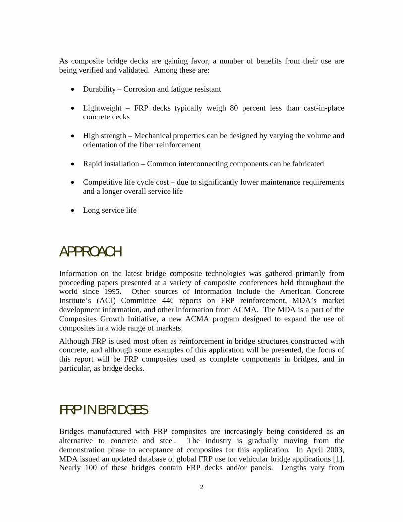
As composite bridge decks are gaining favor, a number of benefits from their use are being verified and validated. Among these are:
• Durability – Corrosion and fatigue resistant
• Lightweight – FRP decks typically weigh 80 percent less than cast-in-place concrete decks
• High strength – Mechanical properties can be designed by varying the volume and
orientation of the fiber reinforcement
• Rapid installation – Common interconnecting components can be fabricated
• Competitive life cycle cost – due to significantly lower maintenance requirements and a longer overall service life
• Long service life
APPROACH Information on the latest bridge composite technologies was gathered primarily from proceeding papers presented at a variety of composite conferences held throughout the world since 1995. Other sources of information include the American Concrete Institute’s (ACI) Committee 440 reports on FRP reinforcement, MDA’s market development information, and other information from ACMA. The MDA is a part of the Composites Growth Initiative, a new ACMA program designed to expand the use of composites in a wide range of markets.
Although FRP is used most often as reinforcement in bridge structures constructed with concrete, and although some examples of this application will be presented, the focus of this report will be FRP composites used as complete components in bridges, and in particular, as bridge decks.
FRP IN BRIDGES Bridges manufactured with FRP composites are increasingly being considered as an alternative to concrete and steel. The industry is gradually moving from the demonstration phase to acceptance of composites for this application. In April 2003, MDA issued an updated database of global FRP use for vehicular bridge applications [1]. Nearly 100 of these bridges contain FRP decks and/or panels. Lengths vary from
2

approximately 16 feet to over 600 feet for the Bromley South Bridge in Kent, England. Likewise, MDA issued a database for pedestrian bridge applications. At least 34 pedestrian bridges are identified as containing FRP decks and/or panels [3]. According to MDA, hundreds of vehicular and pedestrian bridges containing FRP as decks, beams, trusses, rebar, grid, tendons, cables, or panels have been installed worldwide [1, 3]. Examples of FRP used as Reinforcement in Bridges The Beddington Trail highway bridge in Calgary is one of the first in Canada to be outfitted with FRP tendons and a system of structurally integrated optical sensors for remote monitoring [4]. The bridge, a two span structure, opened to traffic in 1993. Two different types of FRP tendons (CFRP tendons and rods) were used to pretension six precast concrete girders. Figure 1 shows the bridge during construction.
Figure 1. Beddington Trail Bridge during construction.
The first steel-free concrete bridge deck slab in the world was achieved through the use of FRP rather than steel reinforcement [5]. The revolutionary slab was cast in 1995 on the Salmon River Bridge, part of the Trans Canada 104 Highway near Kemptown, Nova Scotia, Canada. Construction of the bridge, which consists of two 31-meter spans, includes a steel-free deck over one span and a conventional steel reinforced deck over the other. The steel-free deck contains no steel rebar. Instead, longitudinal beams or girders support it. The load is transferred from the deck to the supporting girders in the same way that an arch transfers loads to supporting columns. Although steel straps are applied to tie the girders together, they are not embedded in the concrete and can be easily monitored and inexpensively replaced. Also, with no steel inside the concrete, no unnecessary weight is added, meaning thinner deck designs. The Salmon River steel-free bridge deck has withstood a number of Canadian winters. Intelligent Sensing for Innovative Structures (ISIS) of Canada reports that it appears to be defying the conventional approach to building steel-reinforced bridge decks [5]. Figure 2 shows the Salmon River Bridge during construction.
3

Figure 2. Salmon River Bridge construction in progress.
The Bridge Street Bridge in Southfield, Michigan, is the first vehicular concrete bridge in the U.S. to employ carbon FRP (CFRP) as the principal structural reinforcement [6]. The bridge was constructed in 2001 using pretensioned CFRP tendons and post-tensioned CFRP cable strands, as well as CFRP grid reinforcement (Figure 3).
Figure 3. Installation of CFRP reinforced concrete sections on the Bridge Street Bridge.
Examples of FRP used as Bridge Deck Material While the two bridges shown in Figures 1 and 2 contain innovative FRP reinforcement, Figures 4 to 7 below show a variety of bridge decks using FRP as the primary (deck) material.
4

Figure 4. West Virginia University FRP composite bridge deck projects. (A) FRP deck
panel field installation using adhesive bonding. (B) Preparing to apply second FRP deck panel section. (C) Panels are connected to stringers using mechanical fasteners and
adhesive bonding.
Figure 5. FRP composite bridge deck panels for installation on Kansas State Highway 126
west of Pittsburg, Kansas. Panels manufactured by Kansas Structural Composites Inc.
Figure 6. Modular FRP bridge in West Virginia manufactured by Creative Pultrusions.
Figure 7. The Bonds Mill Lift Bridge in Stonehouse, England was one of the first FRP
bridges built for vehicular traffic (1994).
5
FRP composite deck systems have been studied in recent years to verify and validate the benefits of composite materials for this application. However, several issues are still being debated and researched, including:
• Deflection/Design Criteria • Long Term Performance • Extreme Temperature Behavior • Connections • Overlays • Specifications • Higher initial costs – Up to 2 to 3 times that of conventional decks • Manufacturing methods
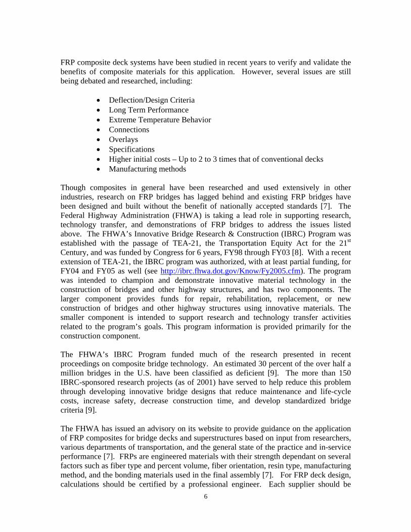
Though composites in general have been researched and used extensively in other industries, research on FRP bridges has lagged behind and existing FRP bridges have been designed and built without the benefit of nationally accepted standards [7]. The Federal Highway Administration (FHWA) is taking a lead role in supporting research, technology transfer, and demonstrations of FRP bridges to address the issues listed above. The FHWA’s Innovative Bridge Research & Construction (IBRC) Program was established with the passage of TEA-21, the Transportation Equity Act for the 21st Century, and was funded by Congress for 6 years, FY98 through FY03 [8]. With a recent extension of TEA-21, the IBRC program was authorized, with at least partial funding, for FY04 and FY05 as well (see http://ibrc.fhwa.dot.gov/Know/Fy2005.cfm). The program was intended to champion and demonstrate innovative material technology in the construction of bridges and other highway structures, and has two components. The larger component provides funds for repair, rehabilitation, replacement, or new construction of bridges and other highway structures using innovative materials. The smaller component is intended to support research and technology transfer activities related to the program’s goals. This program information is provided primarily for the construction component. The FHWA’s IBRC Program funded much of the research presented in recent proceedings on composite bridge technology. An estimated 30 percent of the over half a million bridges in the U.S. have been classified as deficient [9]. The more than 150 IBRC-sponsored research projects (as of 2001) have served to help reduce this problem through developing innovative bridge designs that reduce maintenance and life-cycle costs, increase safety, decrease construction time, and develop standardized bridge criteria [9]. The FHWA has issued an advisory on its website to provide guidance on the application of FRP composites for bridge decks and superstructures based on input from researchers, various departments of transportation, and the general state of the practice and in-service performance [7]. FRPs are engineered materials with their strength dependant on several factors such as fiber type and percent volume, fiber orientation, resin type, manufacturing method, and the bonding materials used in the final assembly [7]. For FRP deck design, calculations should be certified by a professional engineer. Each supplier should be
6
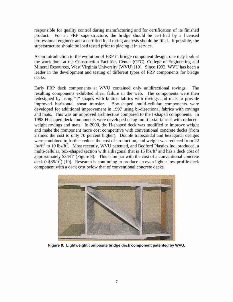
responsible for quality control during manufacturing and for certification of its finished product. For an FRP superstructure, the bridge should be certified by a licensed professional engineer and a certified load rating analysis should be filed. If possible, the superstructure should be load tested prior to placing it in service. As an introduction to the evolution of FRP in bridge component design, one may look at the work done at the Construction Facilities Center (CFC), College of Engineering and Mineral Resources, West Virginia University (WVU) [10]. Since 1992, WVU has been a leader in the development and testing of different types of FRP components for bridge decks. Early FRP deck components at WVU contained only unidirectional rovings. The resulting components exhibited shear failure in the web. The components were then redesigned by using “I” shapes with knitted fabrics with rovings and mats to provide improved horizontal shear transfer. Box-shaped multi-cellular components were developed for additional improvement in 1997 using bi-directional fabrics with rovings and mats. This was an improved architecture compared to the I-shaped components. In 1998 H-shaped deck components were developed using multi-axial fabrics with reduced-weight rovings and mats. In 2000, the H-shaped deck was modified to improve weight and make the component more cost competitive with conventional concrete decks (from 2 times the cost to only 70 percent higher). Double trapezoidal and hexagonal designs were combined to further reduce the cost of production, and weight was reduced from 22 lbs/ft2 to 19 lbs/ft2. Most recently, WVU patented, and Bedford Plastics Inc. produced, a multi-cellular, box-shaped section with a diagonal that is 15 lbs/ft2 and has a deck cost of approximately $34/ft2 (Figure 8). This is on par with the cost of a conventional concrete deck (~$35/ft2) [10]. Research is continuing to produce an even lighter low-profile deck component with a deck cost below that of conventional concrete decks.
Figure 8. Lightweight composite bridge deck component patented by WVU.
7
ISSUES IN FRP BRIDGES Specific FHWA recommendations, recent research, and advances in each of the issue areas listed previously in this report, are presented below. Deflection/Design Criteria FRP's low modulus of elasticity (stiffness) leads to a deflection driven design, which does not allow a designer to fully capitalize on FRP's strength [7]. The resulting structures may possess very high factors of safety for strength. A thorough analysis of the material's behavior requires a finite element model [11].
Much research has been conducted on the static performance of coupon-sized specimens. Less research has focused on the fatigue, long-term creep, and environmental durability of structural components. In spite of this, the FHWA provides guidance on designing for these properties [7]:
• Predicted strains under design load shall be <20 percent of the FRP composites minimum guaranteed ultimate strength (base on coupon testing)
• An environmental durability factor of 0.65 may be applied to account for degradation of material properties over time
• Typically, deflection should be kept at 1/800 of the supporting span length
• If failure in a manner other than tension in the laminate is expected, a safety factor of 5 should be applied
• Protect exposed surfaces from ultraviolet exposure using suitable coatings or UV inhibitors. Acceptable wearing surfaces should be designated and provided by the manufacturer.
• A joint over the bridge seat can be eliminated by carrying the FRP deck over the abutment stem to terminate on the approach side of the bridge. This allows any joint leakage to weep into the fill rather than onto the seat.
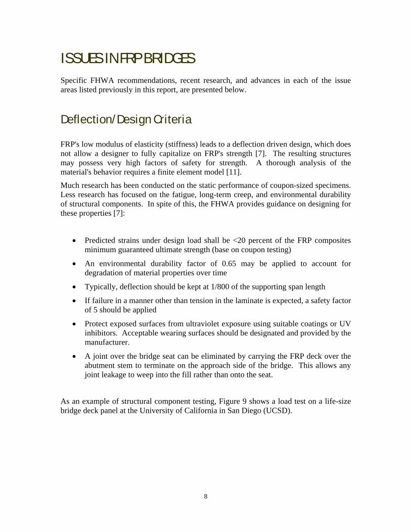
As an example of structural component testing, Figure 9 shows a load test on a life-size bridge deck panel at the University of California in San Diego (UCSD).
8

Figure 9. Load test on a GFRP deck panel at UCSD.
Researchers at Virginia Technical University are developing a stress analysis model for use in strength and life predictions for an actual hybrid FRP bridge beam, with the goal of globally applying the analysis to other FRP structures [12]. In 2002, they reported the results of full scale testing on pultruded double web beams manufactured by Strongwell Corporation. The failure mechanism, delamination at the outer free edges and/or at the inner ply drop-offs on the compressive flange, was used to develop the analysis. Future work planned, at the time of reporting, involved integrating the stress analysis into a strength prediction and developing a life prediction to determine durability under fatigue and environmental aging.
Extreme Temperatures Response to thermal change is slightly different for FRP than for concrete and steel and requires special consideration when an FRP deck is used on a concrete or steel superstructure or when FRP is used for a superstructure [7]. The resins used in FRPs typically are thermosets with glass transition temperatures (Tg), above room temperature. The Tg of a material is the temperature at which the resin changes from a hard and glassy state to a soft and flexible state. This is not a decomposition of the material, but rather a reversible reaction. Typical Tg values for vinyl esters range from 100 to 120°C, while iso-polyesters are generally slightly lower, sometimes below 100°C, and epoxies are generally higher (130 to 170°C) [13]. It is unlikely that atmospheric conditions encountered by bridge structures, even in a desert, would ever be hot enough to cause an FRP member to transition to a soft state, however extreme atmospheric temperatures have still been shown to be of concern.
The FHWA indicates that thermal gradients will occur between the top and bottom of an FRP deck when surface temperatures change rapidly, causing internal thermal stresses
9
[7]. The stresses can be as large as those from live loads and result in arching actions in the deck. When hollow FRP deck profiles are used, the hollow portions are not able to dissipate heat from the top surface to the bottom as effectively as solid concrete [14]. FHWA recommends that a temperature difference of 100°F shall be assumed in the deck design [7]. In 2002, researchers at the U.S. Army Cold Regions Research and Engineering Laboratory and the University of Maine reported on their evaluation of fatigue in FRP composite bridge deck systems under extreme temperatures [15]. The temperatures chosen for the study were –30°C and +50°C. Three full-size composite deck prototypes and one FRP-concrete hybrid deck prototype were tested, along with a conventional reinforced concrete bridge system, using simulated wheel loads created by hydraulic actuators. Quasi-static load tests were conducted periodically throughout the exposures to evaluate the load-deflection and load-strain responses at several points along the deck. After ten million cycles at each temperature, no significant distress was observed in any of the composite decks. However, hairline cracks were observed in the tension region over the hybrid deck. The load deflection stiffness of the FRP composite decks was substantially affected by extreme temperature levels, and was more susceptible to extreme temperature changes than to the ten million cumulative load cycles. The FRP composite decks fabricated by the Vacuum-Assisted Resin Transfer Molding (VARTM) Process and by the pultrusion process had significantly more deflection than that of the conventional and hybrid bridges. The FRP composite deck fabricated by the hand-lay-up contact molding process, however, exhibited little change in comparison to the conventional concrete deck. WVU researchers conducted thermal testing on two FRP bridge decks types, 4 and 8-inch deep [14]. Top surfaces were heated to approximately 150°F while the bottom surfaces were kept at room temperature. In general, the decks exhibited a “hogging” effect (upward convexity). Additionally, a significant amount of residual strain remained in the decks at the end of each thermal cycle, leading to cracking in the wearing surfaces. Two FRP decks on actual bridges in the field were also exposed to direct sunlight. This induced compressive stresses in the decks. Cooling tests were conducted on test decks. The top surfaces of the decks were brought to approximately -20°F using dry ice. The decks exhibited a sagging effect, but there was no significant residual strain after the decks were brought to room temperature. Freeze-thaw degradation is a concern for concrete bridge decks because the cycling can cause cracks to develop in the upper surface [16]. This is due to concrete being a porous material. Water soaks into the concrete and alternately freezes and thaws, expands and contracts, creating stresses that can fracture the concrete. Testing on FRP deck materials has shown that FRP itself is not particularly susceptible to freeze-thaw degradation. However, the bonded combination of concrete and FRP is susceptible. Water, if it is able to travel through the porous concrete and accumulate at the FRP-concrete interface, freezes and expands, inducing forces to damage the FRP-concrete bond. FRP deck forms with concrete cores were tested at the University of Wisconsin using accelerated freeze-thaw cycling to determine the susceptibility of the bond between the FRP and the concrete to freeze-thaw degradation [16]. A direct shear test was used. The study found a reduction in bond strength for the conditioned specimens. However, the test allowed the direct contact of water with the FRP concrete interface, whereas in a real
10
FRP concrete deck, the water would need to permeate through the FRP deck to get to the interface, a much less likely scenario.
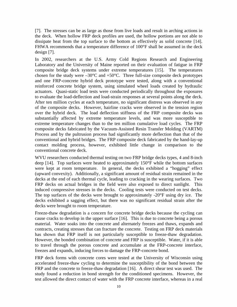
Long-term Performance There are few FRP bridges that have been in service for a substantial length of time. The first FRP bridge deck in the U.S. to carry public traffic was built in November 1996 in Russell County, Kansas [8]. FRP material properties like strength and stiffness naturally degrade over time. The resultant tendency to creep must be addressed in the design. Appropriate strength reduction factors need to be used to insure adequate stiffness over the entire service life of the structure [7]. In 2000, fatigue tests were performed by Georgia Institute of Technology on GFRP sandwich panels designed to resist highway traffic loading [17]. The end of the service life was evidenced by the gradual loss of stiffness under constant load amplitude fatigue loading. Panels whose fatigue load is approximately 30 percent of their static strength appear to demonstrate an infinite fatigue life. Static tests to failure indicated that the panels demonstrated significant system ductility, that is, they will still carry their design loading even after deflections have reached extreme levels. A fatigue performance test for FRP decks was developed by the University of Maine and the U.S. Army Construction Engineering Research Laboratory [18]. Stiffness degradation and reduction in failure load after load cycling at ambient temperature were used to assess the fatigue performance of a modular pultruded FRP deck. The deck was designed using a double trapezoid and hexagon architecture. The resin used was a weather-resistant vinyl ester. After two million cycles, the deck was in satisfactory condition with no major fatigue damage. In the general FRP arena, 10-year-old installations of FRP fabric wrap on bridge columns in California and Pennsylvania were surveyed and the materials were revealed to be in excellent condition [19,20]. Interestingly, the retrofitted columns in California even endured the 1994 Northridge earthquake with little or no damage, while similar nearby columns, not yet retrofitted, exhibited classical failure modes, demonstrating the effectiveness of the FRP retrofits. Other studies by the University of Toronto and others have demonstrated that FRP exhibits satisfactory long-term performance in freeze-thaw, UV radiation, and chloride environments. Researchers at Michigan State University studied the effects of freeze thaw, rate of column corrosion, wet-dry cycling, impact, and high temperatures on corrosion damaged columns retrofitted with FRP wraps. Testing revealed no damage from these conditions with the exception of an extreme temperature of 200°C resulting in degradation of the epoxy used to wrap the FRP onto the columns. Figure 10 shows a typical CFRP wrap on a bridge column.
11
Figure 10. MBrace CFRP composite from Master Builders Technologies being applied to a
concrete bridge column.
A 15-year durability study on FRP composite dowel bars used in roadways was conducted by Ohio University and the Ohio Department of Transportation [21]. In 1983 and 1985, FRP dowel bars were installed in contraction joints of sections of interstate and state roads, along with epoxy-coated mild steel dowel bars. The FRP dowels were composed of 78 percent by weight E-glass continuous glass fibers and 22 percent vinyl ester resin. After approximately 15 years in the field, the steel dowel bars had lost their epoxy coating and corrosion was evident on all bars inspected. The FRP composite dowel bars, on the other hand, appeared to be in excellent condition. Laboratory tests to measure tensile strength, stiffness, shear strength, and load transfer efficiency showed that the FRP dowels were virtually unaffected by 15 years of high-alkaline concrete, de-icing salts, and other environmental effects. NFESC conducted accelerated marine exposure tests on a variety of FRP composite coupons to determine variations in mechanical properties for infrastructure applications [13]. The rectangular coupons were pultruded and included two vinyl ester formulations, two polyesters, a phenolic and an epoxy-polyamide. The GFRP coupons were divided into test groups and exposed to a variety of conditions, including:
• Oxygen-rich atmosphere and salt water spray for 12 months • Oxygen-rich atmosphere and salt water submersion for 12 months • Freezer (-20° C) for 9 months • Salt fog chamber at 95° F for 18 months • Dry heat (95° F) for 120 days • UV exposure (70° C cycling) for 90 days
12
Results of tensile and flexural strength testing indicated that exposure to dry gentle heat, UV radiation, and freezing temperatures had little or no effect on the composites. Exposure to seawater caused the greatest deterioration of the flexural and tensile strengths of the composites. Significant degradation was seen in both the salt fog test and the oxygen rich experiments for the epoxy-polyamide. The most resistant material appeared to be one of the two vinyl ester formulations. Vinyl esters have been documented in the literature to be one of the most weather-resistant resins for composite use. Overall, the composites performed well in comparison to the known poor performance of steel in corrosive environments.
Connections FRP structural members are generally much lighter in weight than their more traditional material counterparts. Because of this, the live load to dead load ratio for the FRP structure may be larger than for an equivalent structure built with a material such as steel. The FRP structure may undergo higher loading ranges, exacerbating the fatigue sensitivity of the connections. The FHWA advises that if an FRP deck is being installed on a steel superstructure, composite action between the FRP and the steel is not to be assumed in capacity calculations [7]. The design of the interface must ensure composite action, or provide a slip mechanism to prevent it. The use of FRP deck systems with steel beams has several advantages including low weight of superstructure, fast erection, ease of load capacity upgrades, and a wide range of structural forms. According to researchers at the University of Western Sydney in Australia, complete shear connection is necessary for steel composite bridge design due to the cyclic loading conditions on the bridge over its lifetime [22]. The shear connection relates to the interaction between the steel beams and the deck such that the two components act together. Also, FRP is known to not be able to redistribute significant shear forces to other connectors along the bridge. Each connector should be designed to resist the maximum shear force at each connection site. To determine the design criteria for composite connections of the FRP and steel system it is necessary to determine the load-slip relationship between the shear connector and the FPR deck and to determine the behavior of the FRP material under service and ultimate loads. Three basic types of connections exist for FRP materials: discrete mechanical, continuous adhesive, and a combination of mechanical and adhesive connection. It is known that the strength of the connections is influenced by torsional buckling or failure of the FRP material induced by high stress concentrations, as well as by the orientation of the fibers in the FRP material [22]. Strength is reduced by more than 20 percent when the fibers are oriented 90-degrees to the direction of the applied load [22]. Studies done at the Royal Military College of Canada demonstrated that connections in FRP components are sensitive to fatigue loading [23]. Fatigue tests on three types of connections were performed in cyclic tension, cyclic compression, and reversed cyclic tension-compression. The three types of connections were “bolted” (using mild steel
13

bolts to connect three FRP members), “bonded” (using polyurethane structural adhesive), and “combined bolted-bonded” configuration. The FRP members consisted of alternating layers of randomly oriented fiber mat and unidirectional fiber ribs pultruded in a vinyl ester resin. Three sections (channel–tube–channel) were used for each specimen. The connections were double lap joints. Most of the bonded connections failed abruptly when their bonding strengths ceased to resist the fatigue load after a certain number of cycles. Residual capacity was found after the initial failure modes had begun in the bolted and combination connections. With increasing number of cycles, slippage increased in all connection types; the greatest slippage was found in the bolted connections. The bolted-only connections had the lowest tensile and compressive monotonic strengths of the three connection types tested. Regardless of connection type, fatigue lives were longer in unidirectional tension than in compression. The greatest overall fatigue life was observed in connections using both bolts and bonding agent. The University of West Virginia tested two connection types with cellular box sections for joint efficiency, transverse load distribution, composite action, and maximum deflections and stresses [22]. Results indicated there was very little transverse load distribution in either the adhesively bonded/bolted connection type or the bolted connection (with fibers in the transverse direction). The joints did not provide complete shear transfer. Composite FRP connections should allow for good fatigue behavior and designs should include proper fiber orientation and minimization of stress concentrations. Further research is needed to develop new connection systems that provide complete shear connection and transfer the longitudinal forces throughout the deck. Recent Defense Advanced Research Project Agency (DARPA) projects investigating the use of Martin Marietta Composite’s DuraSpan® composite deck beams also examined the connections [22]. A demonstration bridge in Darke County, Ohio, was installed using welded headed shear studs. Tests showed the connections exhibited significant ductility. The Kings Stormwater Channel Bridge in California used welded headed shear studs with discontinuous concrete haunches, welded headed shear studs with continuous concrete haunch, and high strength steel bolts with no haunches. The shear studs with discontinuous concrete haunches failed due to large cracks in the bottom of the haunches. The continuous haunches exhibited the best behavior, and the high strength bolts indicated a bearing failure of the deck. The Darke County and Kings Stormwater Channel Bridges are shown in Figures 11 and 12, respectively.
14

Figure 11. Darke County, Ohio – An extensive testing program was conducted at the
University of Delaware to study the composite structure.
Figure 12. The Kings Stormwater Channel Bridge deck in California achieves composite
bending action with carbon composite shell girders filled with lightweight concrete.
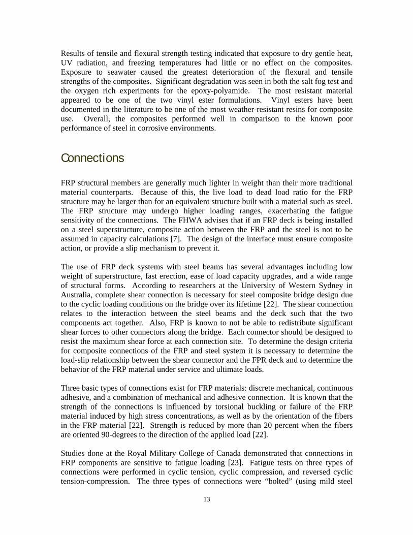
The Institute of Steel Construction in Aachen, Germany has designed a prototype lightweight emergency bridge and tested the bonded connections [24]. The connections consisted of bonded steel plates at the FRP profile joints. The bonding adhesive used was a 2-component impregnated epoxy resin. Load to failure tests revealed failure by delamination near the bonded surface of the FPR profiles. Temperature testing, both at constant temperatures and cycling, showed sufficient ultimate resistance of the connections for temperatures from –25 to +40°C. Failures at constant temperatures occurred primarily through delamination of the FRP itself. Recently, a commercial composites vendor has developed an FRP connector. FIBREBOLT®, by Strongwell Inc., consists of a pultruded stud with threads cut in a glass mat reinforced outer layer (the center of the stud is unidirectionally reinforced for high strength) and a molded nut. FIBREBOLT® does not possess the thread shear strength of steel, but has sufficient strength to be a viable alternative in structures where fastener corrosion is a concern or where metal fasteners are not permitted (antennae housings, computer equipment testing structures, etc.).
15
® by Strongwell) Figure 13. Pultruded FRP connectors (FIBREBOLT
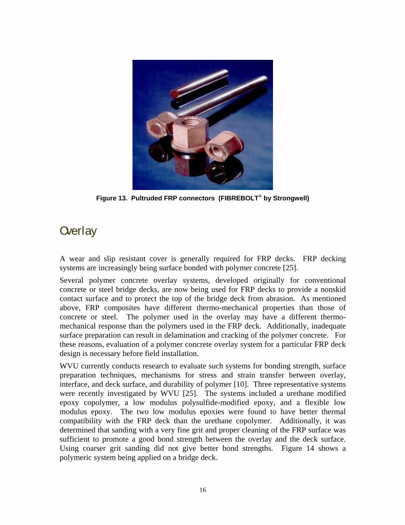
Overlay A wear and slip resistant cover is generally required for FRP decks. FRP decking systems are increasingly being surface bonded with polymer concrete [25]. Several polymer concrete overlay systems, developed originally for conventional concrete or steel bridge decks, are now being used for FRP decks to provide a nonskid contact surface and to protect the top of the bridge deck from abrasion. As mentioned above, FRP composites have different thermo-mechanical properties than those of concrete or steel. The polymer used in the overlay may have a different thermo-mechanical response than the polymers used in the FRP deck. Additionally, inadequate surface preparation can result in delamination and cracking of the polymer concrete. For these reasons, evaluation of a polymer concrete overlay system for a particular FRP deck design is necessary before field installation. WVU currently conducts research to evaluate such systems for bonding strength, surface preparation techniques, mechanisms for stress and strain transfer between overlay, interface, and deck surface, and durability of polymer [10]. Three representative systems were recently investigated by WVU [25]. The systems included a urethane modified epoxy copolymer, a low modulus polysulfide-modified epoxy, and a flexible low modulus epoxy. The two low modulus epoxies were found to have better thermal compatibility with the FRP deck than the urethane copolymer. Additionally, it was determined that sanding with a very fine grit and proper cleaning of the FRP surface was sufficient to promote a good bond strength between the overlay and the deck surface. Using coarser grit sanding did not give better bond strengths. Figure 14 shows a polymeric system being applied on a bridge deck.
16

Figure 14. Application of a bridge deck overlay system.
Specifications, Codes, and Standards There are a lack of design standards and conventions for FRP material characterization. Currently most available designs are proprietary and there is no standardized manufacturing process. However, a number of committee activities from professional organizations are now addressing the recommended use and specification of FRP composites. Many organizations have published codes, standards, test methods, and specifications for FRP composites and their respective products. In an effort to standardize composites in transportation infrastructure, the American Association of State Highway and Transportation Officials (AASHTO) established a technical committee in 1997 called “T-21 Composites” [26]. This technical committee, now under the Subcommittee on Bridges and Structures and called Fiber Reinforced Polymer Composites, has an ongoing effort to develop design guidelines for the use of composites in bridge applications including FRP reinforced concrete, concrete repair, and vehicular bridge deck panels. The American Concrete Institute, and its Committee 440 “Fiber Reinforced Plastic Reinforcement” with ten different subcommittees, address FRP composite topics related to concrete such as research needs, repair, rebar, prestressing, and stay-in-place structural formwork. Several publications of the Committee include:
• ACI 440.1R-03, Guide for the Design and Construction of Concrete Reinforced with FRP Bars
• ACI 440.2R-02, Guide for the Design and Construction of Externally bonded
FRP Systems for Strengthening Concrete Structures
17

• ACI 440-3R-04, Guide Test Methods for Fiber Reinforced Polymers (FRP) for
Reinforcing or Strengthening Concrete Structures • ACI 440.4R-04, Prestressing Concrete Structures with FRP Tendons.
Several ASTM committees are currently working on consensus test methods for the use of FRP rebar, repair materials, and pultruded structural profiles [26]. In ASTM D20.18.01 (FRP Materials for Concrete) committee, industry experts are addressing materials and products to develop standard test methods for FRP rebar and repair materials. ASTM D20.18.02 is a committee focused on the development of test methods for FRP pultruded profiles and shapes. The ASTM D30.30.01 (Composites for Civil Engineering) committee addresses FRP composites products used construction. In related efforts, a number of other countries have begun developing codes and standards for the use of FRP in infrastructure. A task group in Switzerland was established by the Swiss code committee for concrete structures in 1999 [27]. The task group consisted of researchers, consulting engineers, and contractors. Their goal was to write a user-friendly code that proposes a consistent design procedure for externally bonded reinforcement of structures, both steel and CFRP plates bonded on various substrates. They produced a document that addresses design and structural analysis and dimensioning, as well as materials, execution, quality assurance, and health and safety. The document was scheduled for final approval by the end of 2003. In Sweden, a Design Guideline for FRP strengthening of concrete structures has existed since the late 1990’s [28]. The Guideline is based on theoretical analyses, laboratory and full-scale testing, as well as practical experience. The document includes information on strengthening for bending, shear, torsion, and confinement, as well as execution of strengthening work and safety factors. The Guideline has reportedly led to an increase in the use of FRP for structural strengthening in Sweden. Japan has been actively reviewing FRP research and evaluation criteria and methods since 1988 [29]. In 1996, the Architectural Institute of Japan formed a research committee to compile a design and construction guideline for FRP related to seismic retrofitting using fiber sheet. By 2002, a design guideline was published that includes evaluation methods of material characteristics, fire resistance, durability and FRP-RC using FRP bars as well as fiber sheet [29]. ISIS of Canada and the Fédération Internationale du Béton (FIB) of France have also published design manuals for externally bonded FRP reinforcement of concrete structures [28]. Higher Initial Cost Composites have a higher initial cost compared to a conventional concrete deck. The unit cost of FRP materials is often more expensive than conventional materials. The current estimated cost of a conventional steel reinforced concrete bridge deck is ~$ 35/ft2 [10]. Early (1990s) FRP bridge decks usually cost more than double this price [10, 25]. Advances in FRP design have brought this cost down. Installed costs for FRP bridge
18
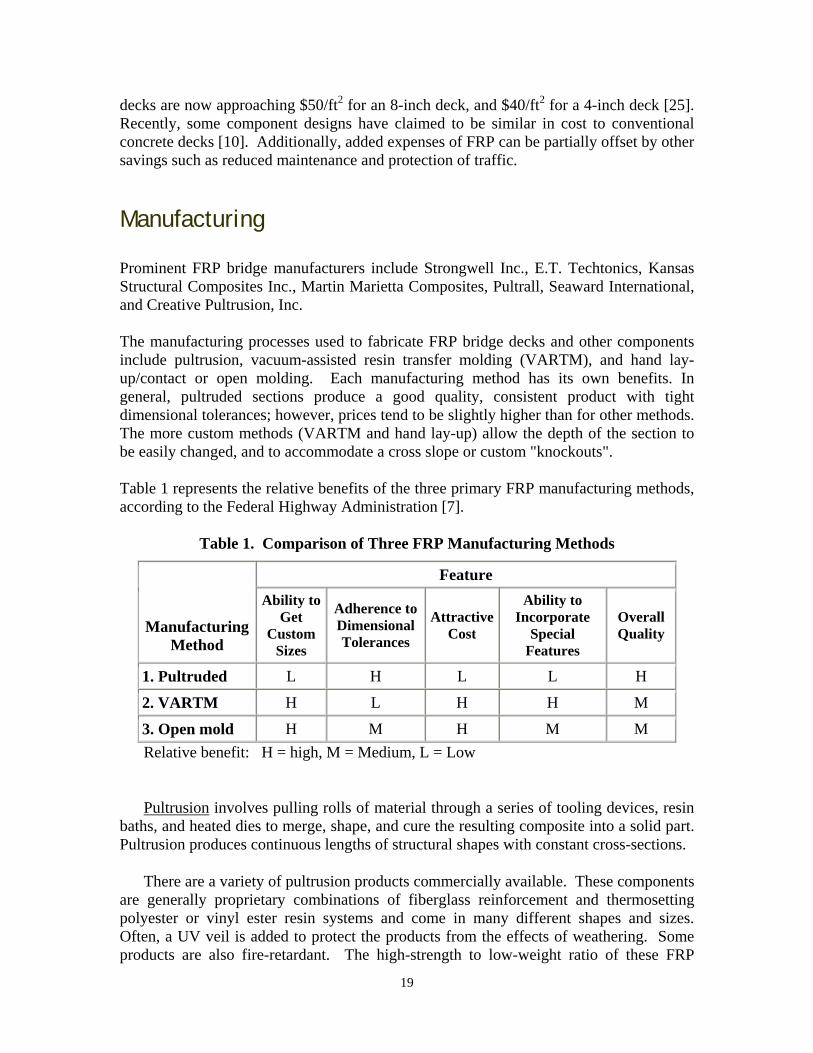
decks are now approaching $50/ft2 2 for an 8-inch deck, and $40/ft for a 4-inch deck [25]. Recently, some component designs have claimed to be similar in cost to conventional concrete decks [10]. Additionally, added expenses of FRP can be partially offset by other savings such as reduced maintenance and protection of traffic. Manufacturing Prominent FRP bridge manufacturers include Strongwell Inc., E.T. Techtonics, Kansas Structural Composites Inc., Martin Marietta Composites, Pultrall, Seaward International, and Creative Pultrusion, Inc. The manufacturing processes used to fabricate FRP bridge decks and other components include pultrusion, vacuum-assisted resin transfer molding (VARTM), and hand lay-up/contact or open molding. Each manufacturing method has its own benefits. In general, pultruded sections produce a good quality, consistent product with tight dimensional tolerances; however, prices tend to be slightly higher than for other methods. The more custom methods (VARTM and hand lay-up) allow the depth of the section to be easily changed, and to accommodate a cross slope or custom "knockouts". Table 1 represents the relative benefits of the three primary FRP manufacturing methods, according to the Federal Highway Administration [7].
Table 1. Comparison of Three FRP Manufacturing Methods
Feature Ability to
Get Custom
Sizes
Ability to Incorporate
Special Features
Adherence to Dimensional Tolerances
Attractive Cost
Overall Quality Manufacturing
Method
L H L L H 1. PultrudedH L H H M 2. VARTM
H M H M M 3. Open moldRelative benefit: H = high, M = Medium, L = Low
Pultrusion involves pulling rolls of material through a series of tooling devices, resin baths, and heated dies to merge, shape, and cure the resulting composite into a solid part. Pultrusion produces continuous lengths of structural shapes with constant cross-sections.
There are a variety of pultrusion products commercially available. These components are generally proprietary combinations of fiberglass reinforcement and thermosetting polyester or vinyl ester resin systems and come in many different shapes and sizes. Often, a UV veil is added to protect the products from the effects of weathering. Some products are also fire-retardant. The high-strength to low-weight ratio of these FRP
19
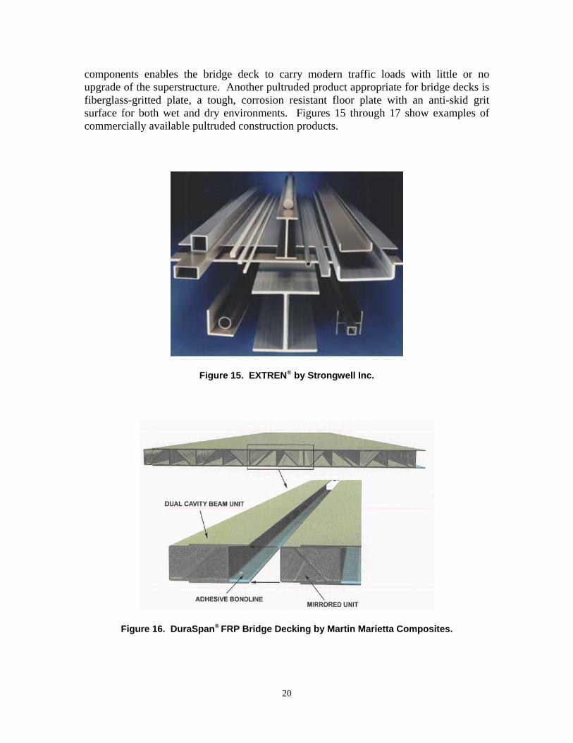
components enables the bridge deck to carry modern traffic loads with little or no upgrade of the superstructure. Another pultruded product appropriate for bridge decks is fiberglass-gritted plate, a tough, corrosion resistant floor plate with an anti-skid grit surface for both wet and dry environments. Figures 15 through 17 show examples of commercially available pultruded construction products.
Figure 15. EXTREN® by Strongwell Inc.
Figure 16. DuraSpan® FRP Bridge Decking by Martin Marietta Composites.
20
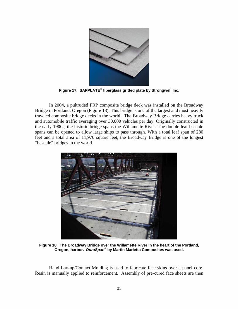
Figure 17. SAFPLATE® fiberglass gritted plate by Strongwell Inc.
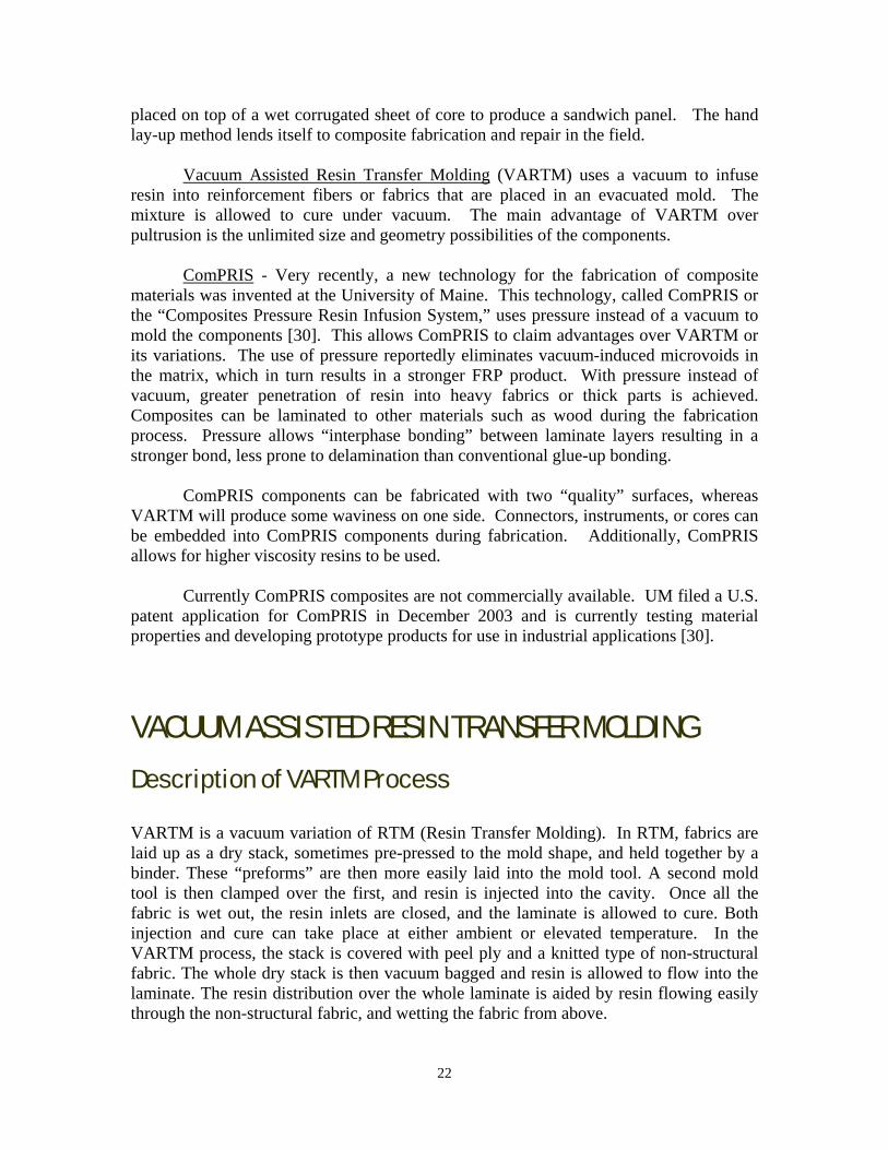
In 2004, a pultruded FRP composite bridge deck was installed on the Broadway
Bridge in Portland, Oregon (Figure 18). This bridge is one of the largest and most heavily traveled composite bridge decks in the world. The Broadway Bridge carries heavy truck and automobile traffic averaging over 30,000 vehicles per day. Originally constructed in the early 1900s, the historic bridge spans the Willamette River. The double-leaf bascule spans can be opened to allow large ships to pass through. With a total leaf span of 280 feet and a total area of 11,970 square feet, the Broadway Bridge is one of the longest “bascule” bridges in the world.
Figure 18. The Broadway Bridge over the Willamette River in the heart of the Portland,
Oregon, harbor. DuraSpan® by Martin Marietta Composites was used.
Hand Lay-up/Contact Molding is used to fabricate face skins over a panel core. Resin is manually applied to reinforcement. Assembly of pre-cured face sheets are then
21
placed on top of a wet corrugated sheet of core to produce a sandwich panel. The hand lay-up method lends itself to composite fabrication and repair in the field.
Vacuum Assisted Resin Transfer Molding (VARTM) uses a vacuum to infuse resin into reinforcement fibers or fabrics that are placed in an evacuated mold. The mixture is allowed to cure under vacuum. The main advantage of VARTM over pultrusion is the unlimited size and geometry possibilities of the components.
ComPRIS - Very recently, a new technology for the fabrication of composite materials was invented at the University of Maine. This technology, called ComPRIS or the “Composites Pressure Resin Infusion System,” uses pressure instead of a vacuum to mold the components [30]. This allows ComPRIS to claim advantages over VARTM or its variations. The use of pressure reportedly eliminates vacuum-induced microvoids in the matrix, which in turn results in a stronger FRP product. With pressure instead of vacuum, greater penetration of resin into heavy fabrics or thick parts is achieved. Composites can be laminated to other materials such as wood during the fabrication process. Pressure allows “interphase bonding” between laminate layers resulting in a stronger bond, less prone to delamination than conventional glue-up bonding.
ComPRIS components can be fabricated with two “quality” surfaces, whereas VARTM will produce some waviness on one side. Connectors, instruments, or cores can be embedded into ComPRIS components during fabrication. Additionally, ComPRIS allows for higher viscosity resins to be used.
Currently ComPRIS composites are not commercially available. UM filed a U.S. patent application for ComPRIS in December 2003 and is currently testing material properties and developing prototype products for use in industrial applications [30].
VACUUM ASSISTED RESIN TRANSFER MOLDING Description of VARTM Process VARTM is a vacuum variation of RTM (Resin Transfer Molding). In RTM, fabrics are laid up as a dry stack, sometimes pre-pressed to the mold shape, and held together by a binder. These “preforms” are then more easily laid into the mold tool. A second mold tool is then clamped over the first, and resin is injected into the cavity. Once all the fabric is wet out, the resin inlets are closed, and the laminate is allowed to cure. Both injection and cure can take place at either ambient or elevated temperature. In the VARTM process, the stack is covered with peel ply and a knitted type of non-structural fabric. The whole dry stack is then vacuum bagged and resin is allowed to flow into the laminate. The resin distribution over the whole laminate is aided by resin flowing easily through the non-structural fabric, and wetting the fabric from above.
22

Figure 19. Schematic of Vacuum Resin Transfer Molding.
Pros and Cons of VARTM The main advantages of VARTM are:
• Large components can be fabricated • Components with varying cross sections, lengths and widths can be fabricated • Cored structures can be produced in one operation • Lower tooling cost due to one side of the tool being the vacuum bag
The main disadvantages of VARTM are:
• A more complex process than other methods • More expensive process than pultrusion • Resins must be low in viscosity, possibly compromising mechanical properties of
the finished composite • Adherence to dimensional tolerances is lower than for pultrusion
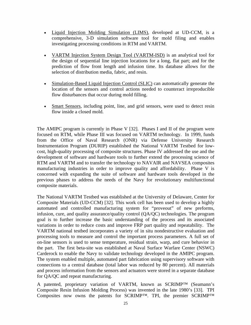
With VARTM, even complex configurations such as a honeycomb structural matrix are possible. Such internal core structures are purported by VARTM FRP vendors to meet or exceed specifications for weight, strength and durability for bridge components. As with pultrusion, the VARTM products are usually proprietary designs. Figures 20 and 21 show examples of a VARTM deck product (produced by the recently defunct Hardcore Composites).
23
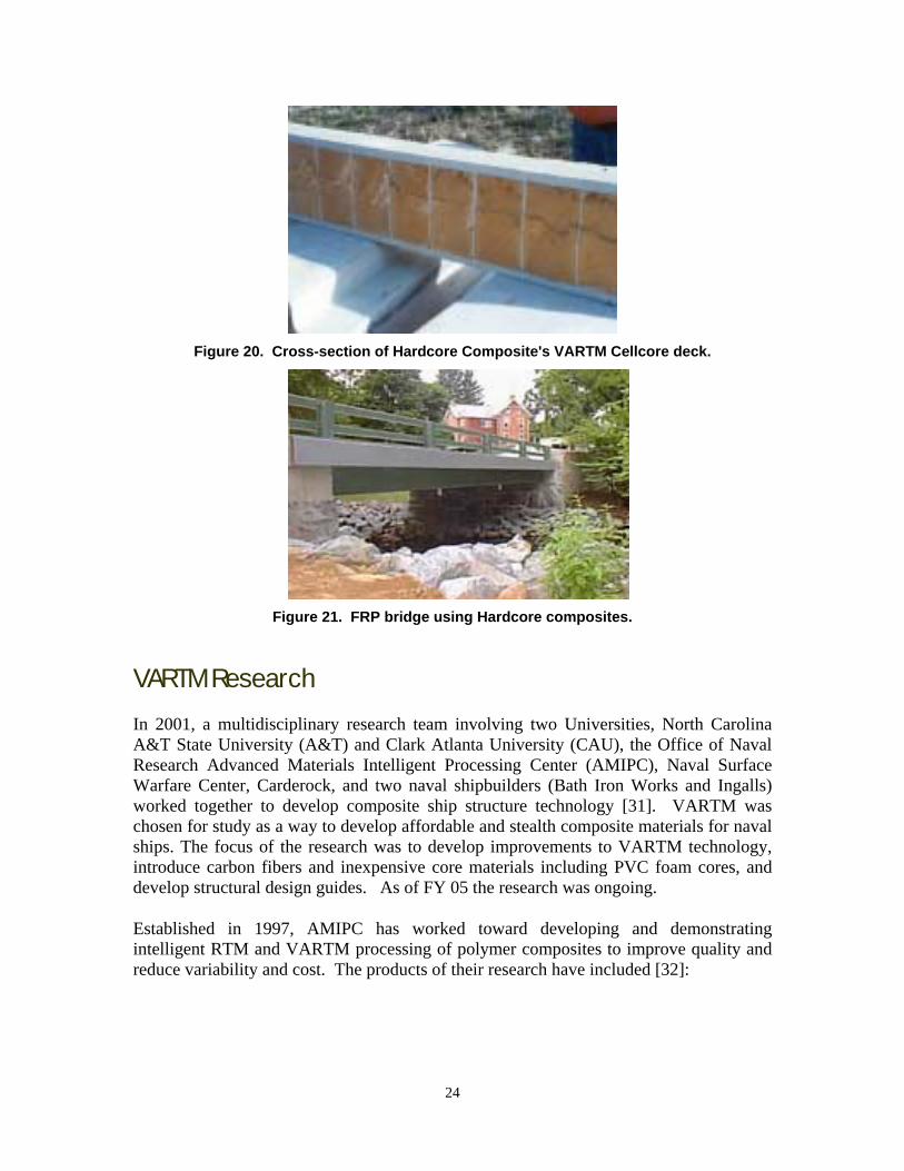
Figure 20. Cross-section of Hardcore Composite's VARTM Cellcore deck.
Figure 21. FRP bridge using Hardcore composites.
VARTM Research In 2001, a multidisciplinary research team involving two Universities, North Carolina A&T State University (A&T) and Clark Atlanta University (CAU), the Office of Naval Research Advanced Materials Intelligent Processing Center (AMIPC), Naval Surface Warfare Center, Carderock, and two naval shipbuilders (Bath Iron Works and Ingalls) worked together to develop composite ship structure technology [31]. VARTM was chosen for study as a way to develop affordable and stealth composite materials for naval ships. The focus of the research was to develop improvements to VARTM technology, introduce carbon fibers and inexpensive core materials including PVC foam cores, and develop structural design guides. As of FY 05 the research was ongoing.
Established in 1997, AMIPC has worked toward developing and demonstrating intelligent RTM and VARTM processing of polymer composites to improve quality and reduce variability and cost. The products of their research have included [32]:
24
• Liquid Injection Molding Simulation (LIMS), developed at UD-CCM, is a comprehensive, 3-D simulation software tool for mold filing and enables investigating processing conditions in RTM and VARTM.
• VARTM Injection System Design Tool (VARTM-ISD) is an analytical tool for
the design of sequential line injection locations for a long, flat part; and for the prediction of flow front length and infusion time. Its database allows for the selection of distribution media, fabric, and resin.
• Simulation-Based Liquid Injection Control (SLIC) can automatically generate the
location of the sensors and control actions needed to counteract irreproducible flow disturbances that occur during mold filling.
• Smart Sensors, including point, line, and grid sensors, were used to detect resin
flow inside a closed mold.
The AMIPC program is currently in Phase V [32]. Phases I and II of the program were focused on RTM, while Phase III was focused on VARTM technology. In 1999, funds from the Office of Naval Research (ONR) via Defense University Research Instrumentation Program (DURIP) established the National VARTM Testbed for low-cost, high-quality processing of composite structures. Phase IV addressed the use and the development of software and hardware tools to further extend the processing science of RTM and VARTM and to transfer the technology to NAVAIR and NAVSEA composites manufacturing industries in order to improve quality and affordability. Phase V is concerned with expanding the suite of software and hardware tools developed in the previous phases to address the needs of the Navy for revolutionary multifunctional composite materials.
The National VARTM Testbed was established at the University of Delaware, Center for Composite Materials (UD-CCM) [32]. This work cell has been used to develop a highly automated and controlled manufacturing system for “proveout” of new preforms, infusion, cure, and quality assurance/quality control (QA/QC) technologies. The program goal is to further increase the basic understanding of the process and its associated variations in order to reduce costs and improve FRP part quality and repeatability. The VARTM national testbed incorporates a variety of in situ nondestructive evaluation and processing tools to measure and control the important process parameters. A full set of on-line sensors is used to sense temperature, residual strain, warp, and cure behavior in the part. The first beta-site was established at Naval Surface Warfare Center (NSWC) Carderock to enable the Navy to validate technology developed in the AMIPC program. The system enabled multiple, automated part fabrication using supervisory software with connections to a central database (total labor was reduced by 80 percent). All materials and process information from the sensors and actuators were stored in a separate database for QA/QC and repeat manufacturing.
A patented, proprietary variation of VARTM, known as SCRIMP™ (Seamann’s Composite Resin Infusion Molding Process) was invented in the late 1980’s [33]. TPI Composites now owns the patents for SCRIMP™. TPI, the premier SCRIMP™
25
manufacturer in the U.S., is using UD-CCM's SMARTMolding system to produce their composites [32]. In the basic SCRIMP™ process, the resin is distributed through the laminate via a flow medium and series of channels, saturating the part. With SCRIMP™, it is possible to flow a large volume of resin, a long way, very quickly. SCRIMP™ is claimed to have almost zero emissions and to produce components of superior uniformity.
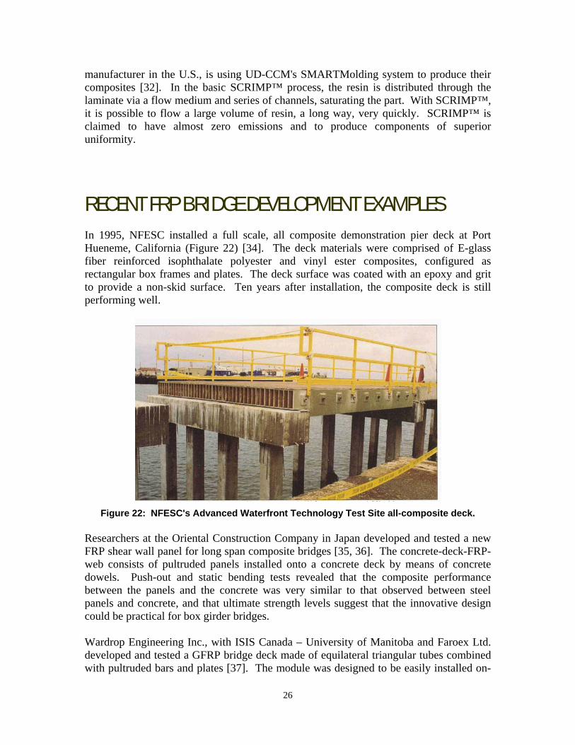
RECENT FRP BRIDGE DEVELOPMENT EXAMPLES In 1995, NFESC installed a full scale, all composite demonstration pier deck at Port Hueneme, California (Figure 22) [34]. The deck materials were comprised of E-glass fiber reinforced isophthalate polyester and vinyl ester composites, configured as rectangular box frames and plates. The deck surface was coated with an epoxy and grit to provide a non-skid surface. Ten years after installation, the composite deck is still performing well.
Figure 22: NFESC's Advanced Waterfront Technology Test Site all-composite deck.
Researchers at the Oriental Construction Company in Japan developed and tested a new FRP shear wall panel for long span composite bridges [35, 36]. The concrete-deck-FRP-web consists of pultruded panels installed onto a concrete deck by means of concrete dowels. Push-out and static bending tests revealed that the composite performance between the panels and the concrete was very similar to that observed between steel panels and concrete, and that ultimate strength levels suggest that the innovative design could be practical for box girder bridges. Wardrop Engineering Inc., with ISIS Canada – University of Manitoba and Faroex Ltd. developed and tested a GFRP bridge deck made of equilateral triangular tubes combined with pultruded bars and plates [37]. The module was designed to be easily installed on-
26
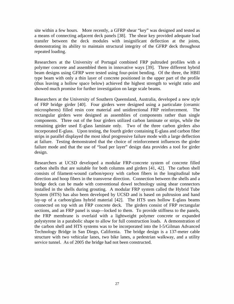
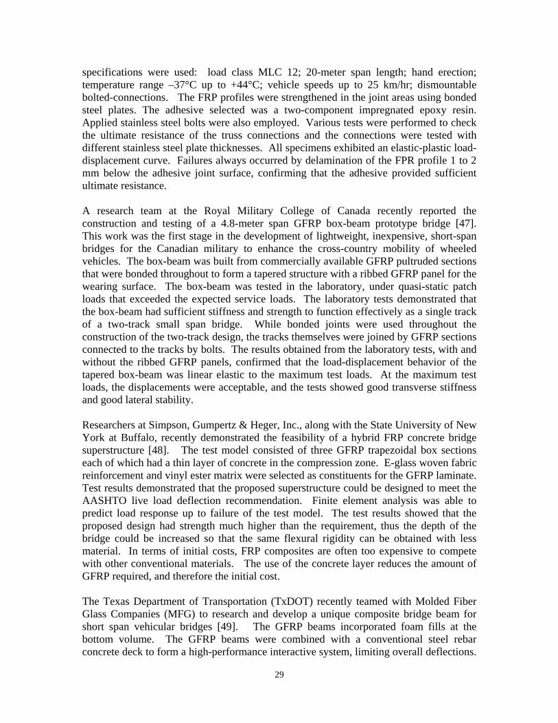
site within a few hours. More recently, a GFRP shear “key” was designed and tested as a means of connecting adjacent deck panels [38]. The shear key provided adequate load transfer between the deck modules with insignificant deflection at the joints, demonstrating its ability to maintain structural integrity of the GFRP deck throughout repeated loading. Researchers at the University of Portugal combined FRP pultruded profiles with a polymer concrete and assembled them in innovative ways [39]. Three different hybrid beam designs using GFRP were tested using four-point bending. Of the three, the HBII type beam with only a thin layer of concrete positioned in the upper part of the profile (thus leaving a hollow space below) achieved the highest strength to weight ratio and showed much promise for further investigation on large scale beams. Researchers at the University of Southern Queensland, Australia, developed a new style of FRP bridge girder [40]. Four girders were designed using a particulate (ceramic microspheres) filled resin core material and unidirectional FRP reinforcement. The rectangular girders were designed as assemblies of components rather than single components. Three out of the four girders utilized carbon laminate or strips, while the remaining girder used E-glass laminate only. Two of the three carbon girders also incorporated E-glass. Upon testing, the fourth girder containing E-glass and carbon fiber strips in parallel displayed the most ideal progressive failure mode with a large deflection at failure. Testing demonstrated that the choice of reinforcement influences the girder failure mode and that the use of “load per layer” design data provides a tool for girder design. Researchers at UCSD developed a modular FRP-concrete system of concrete filled carbon shells that are suitable for both columns and girders [41, 42]. The carbon shell consists of filament-wound carbon/epoxy with carbon fibers in the longitudinal tube direction and hoop fibers in the transverse direction. Connection between the shells and a bridge deck can be made with conventional dowel technology using shear connectors installed in the shells during grouting. A modular FRP system called the Hybrid Tube System (HTS) has also been developed by UCSD and is based on pultrusion and hand lay-up of a carbon/glass hybrid material [42]. The HTS uses hollow E-glass beams connected on top with an FRP concrete deck. The girders consist of FRP rectangular sections, and an FRP panel is snap—locked to them. To provide stiffness to the panels, the FRP membrane is overlaid with a lightweight polymer concrete or expanded polystyrene in a parabolic shape to allow for full construction loads. A demonstration of the carbon shell and HTS systems was to be incorporated into the I-5/Gilman Advanced Technology Bridge in San Diego, California. The bridge design is a 137-meter cable structure with two vehicular lanes, two bike lanes, a pedestrian walkway, and a utility service tunnel. As of 2005 the bridge had not been constructed.
27
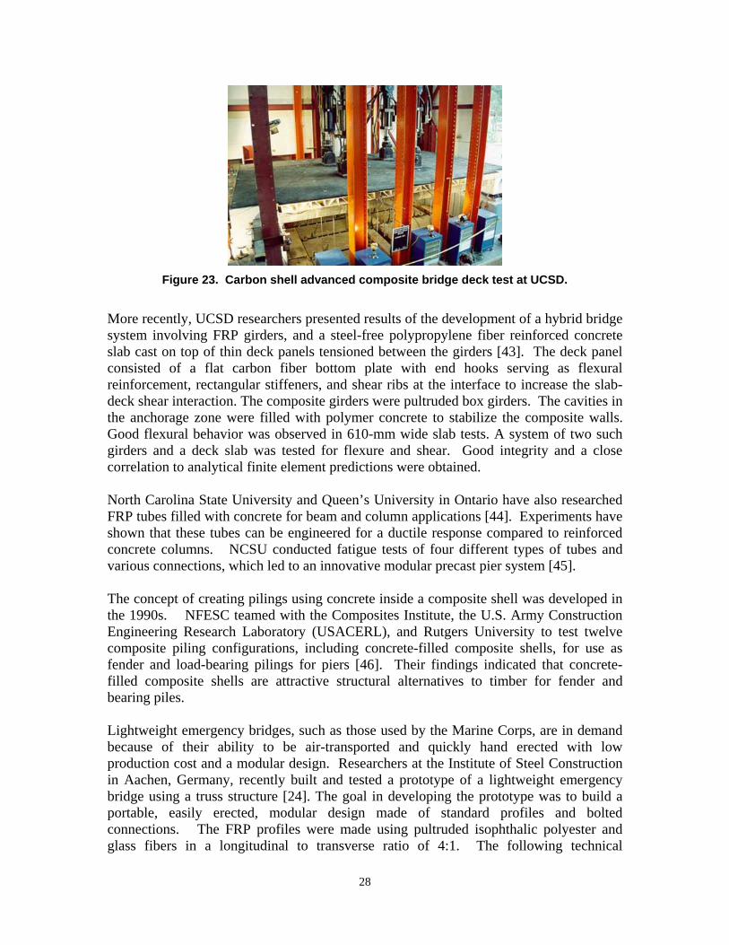
Figure 23. Carbon shell advanced composite bridge deck test at UCSD.
More recently, UCSD researchers presented results of the development of a hybrid bridge system involving FRP girders, and a steel-free polypropylene fiber reinforced concrete slab cast on top of thin deck panels tensioned between the girders [43]. The deck panel consisted of a flat carbon fiber bottom plate with end hooks serving as flexural reinforcement, rectangular stiffeners, and shear ribs at the interface to increase the slab-deck shear interaction. The composite girders were pultruded box girders. The cavities in the anchorage zone were filled with polymer concrete to stabilize the composite walls. Good flexural behavior was observed in 610-mm wide slab tests. A system of two such girders and a deck slab was tested for flexure and shear. Good integrity and a close correlation to analytical finite element predictions were obtained. North Carolina State University and Queen’s University in Ontario have also researched FRP tubes filled with concrete for beam and column applications [44]. Experiments have shown that these tubes can be engineered for a ductile response compared to reinforced concrete columns. NCSU conducted fatigue tests of four different types of tubes and various connections, which led to an innovative modular precast pier system [45]. The concept of creating pilings using concrete inside a composite shell was developed in the 1990s. NFESC teamed with the Composites Institute, the U.S. Army Construction Engineering Research Laboratory (USACERL), and Rutgers University to test twelve composite piling configurations, including concrete-filled composite shells, for use as fender and load-bearing pilings for piers [46]. Their findings indicated that concrete-filled composite shells are attractive structural alternatives to timber for fender and bearing piles. Lightweight emergency bridges, such as those used by the Marine Corps, are in demand because of their ability to be air-transported and quickly hand erected with low production cost and a modular design. Researchers at the Institute of Steel Construction in Aachen, Germany, recently built and tested a prototype of a lightweight emergency bridge using a truss structure [24]. The goal in developing the prototype was to build a portable, easily erected, modular design made of standard profiles and bolted connections. The FRP profiles were made using pultruded isophthalic polyester and glass fibers in a longitudinal to transverse ratio of 4:1. The following technical
28
specifications were used: load class MLC 12; 20-meter span length; hand erection; temperature range –37°C up to +44°C; vehicle speeds up to 25 km/hr; dismountable bolted-connections. The FRP profiles were strengthened in the joint areas using bonded steel plates. The adhesive selected was a two-component impregnated epoxy resin. Applied stainless steel bolts were also employed. Various tests were performed to check the ultimate resistance of the truss connections and the connections were tested with different stainless steel plate thicknesses. All specimens exhibited an elastic-plastic load-displacement curve. Failures always occurred by delamination of the FPR profile 1 to 2 mm below the adhesive joint surface, confirming that the adhesive provided sufficient ultimate resistance. A research team at the Royal Military College of Canada recently reported the construction and testing of a 4.8-meter span GFRP box-beam prototype bridge [47]. This work was the first stage in the development of lightweight, inexpensive, short-span bridges for the Canadian military to enhance the cross-country mobility of wheeled vehicles. The box-beam was built from commercially available GFRP pultruded sections that were bonded throughout to form a tapered structure with a ribbed GFRP panel for the wearing surface. The box-beam was tested in the laboratory, under quasi-static patch loads that exceeded the expected service loads. The laboratory tests demonstrated that the box-beam had sufficient stiffness and strength to function effectively as a single track of a two-track small span bridge. While bonded joints were used throughout the construction of the two-track design, the tracks themselves were joined by GFRP sections connected to the tracks by bolts. The results obtained from the laboratory tests, with and without the ribbed GFRP panels, confirmed that the load-displacement behavior of the tapered box-beam was linear elastic to the maximum test loads. At the maximum test loads, the displacements were acceptable, and the tests showed good transverse stiffness and good lateral stability. Researchers at Simpson, Gumpertz & Heger, Inc., along with the State University of New York at Buffalo, recently demonstrated the feasibility of a hybrid FRP concrete bridge superstructure [48]. The test model consisted of three GFRP trapezoidal box sections each of which had a thin layer of concrete in the compression zone. E-glass woven fabric reinforcement and vinyl ester matrix were selected as constituents for the GFRP laminate. Test results demonstrated that the proposed superstructure could be designed to meet the AASHTO live load deflection recommendation. Finite element analysis was able to predict load response up to failure of the test model. The test results showed that the proposed design had strength much higher than the requirement, thus the depth of the bridge could be increased so that the same flexural rigidity can be obtained with less material. In terms of initial costs, FRP composites are often too expensive to compete with other conventional materials. The use of the concrete layer reduces the amount of GFRP required, and therefore the initial cost. The Texas Department of Transportation (TxDOT) recently teamed with Molded Fiber Glass Companies (MFG) to research and develop a unique composite bridge beam for short span vehicular bridges [49]. The GFRP beams incorporated foam fills at the bottom volume. The GFRP beams were combined with a conventional steel rebar concrete deck to form a high-performance interactive system, limiting overall deflections.
29
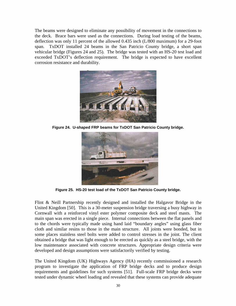
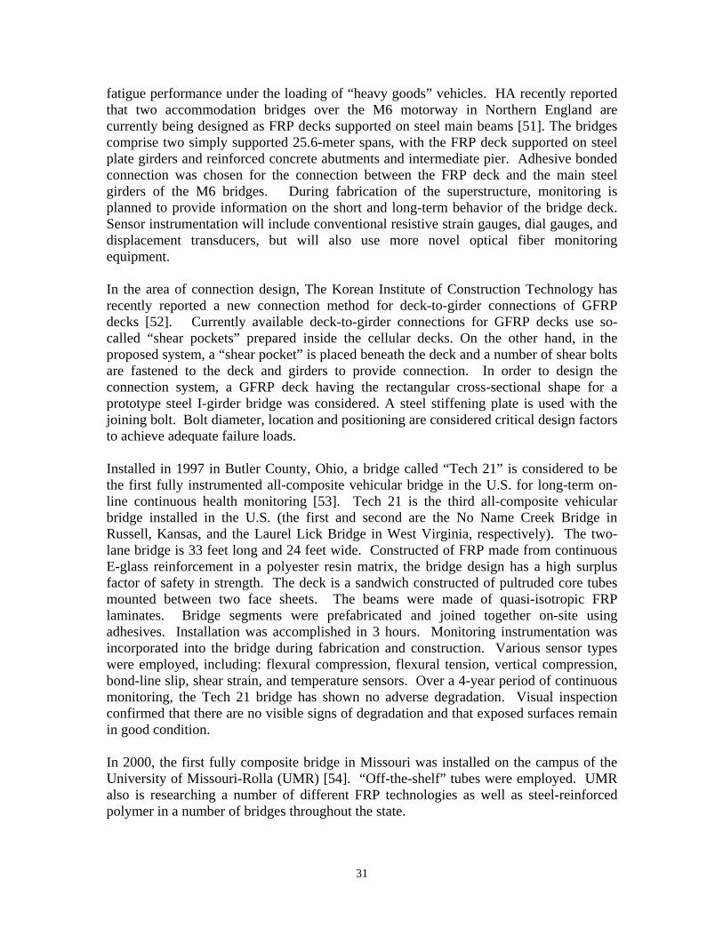
The beams were designed to eliminate any possibility of movement in the connections to the deck. Brace bars were used as the connections. During load testing of the beams, deflection was only 11 percent of the allowed 0.435 inch (L/800 maximum) for a 29-foot span. TxDOT installed 24 beams in the San Patricio County bridge, a short span vehicular bridge (Figures 24 and 25). The bridge was tested with an HS-20 test load and exceeded TxDOT’s deflection requirement. The bridge is expected to have excellent corrosion resistance and durability.
Figure 24. U-shaped FRP beams for TxDOT San Patricio County bridge.
Figure 25. HS-20 test load of the TxDOT San Patricio County bridge.
Flint & Neill Partnership recently designed and installed the Halgavor Bridge in the United Kingdom [50]. This is a 30-meter suspension bridge traversing a busy highway in Cornwall with a reinforced vinyl ester polymer composite deck and steel masts. The main span was erected in a single piece. Internal connections between the flat panels and to the chords were typically made using hand laid “boundary angles” using glass fiber cloth and similar resins to those in the main structure. All joints were bonded, but in some places stainless steel bolts were added to control stresses in the joint. The client obtained a bridge that was light enough to be erected as quickly as a steel bridge, with the low maintenance associated with concrete structures. Appropriate design criteria were developed and design assumptions were satisfactorily verified by testing. The United Kingdom (UK) Highways Agency (HA) recently commissioned a research program to investigate the application of FRP bridge decks and to produce design requirements and guidelines for such systems [51]. Full-scale FRP bridge decks were tested under dynamic wheel loading and revealed that these systems can provide adequate
30
fatigue performance under the loading of “heavy goods” vehicles. HA recently reported that two accommodation bridges over the M6 motorway in Northern England are currently being designed as FRP decks supported on steel main beams [51]. The bridges comprise two simply supported 25.6-meter spans, with the FRP deck supported on steel plate girders and reinforced concrete abutments and intermediate pier. Adhesive bonded connection was chosen for the connection between the FRP deck and the main steel girders of the M6 bridges. During fabrication of the superstructure, monitoring is planned to provide information on the short and long-term behavior of the bridge deck. Sensor instrumentation will include conventional resistive strain gauges, dial gauges, and displacement transducers, but will also use more novel optical fiber monitoring equipment. In the area of connection design, The Korean Institute of Construction Technology has recently reported a new connection method for deck-to-girder connections of GFRP decks [52]. Currently available deck-to-girder connections for GFRP decks use so-called “shear pockets” prepared inside the cellular decks. On the other hand, in the proposed system, a “shear pocket” is placed beneath the deck and a number of shear bolts are fastened to the deck and girders to provide connection. In order to design the connection system, a GFRP deck having the rectangular cross-sectional shape for a prototype steel I-girder bridge was considered. A steel stiffening plate is used with the joining bolt. Bolt diameter, location and positioning are considered critical design factors to achieve adequate failure loads. Installed in 1997 in Butler County, Ohio, a bridge called “Tech 21” is considered to be the first fully instrumented all-composite vehicular bridge in the U.S. for long-term on-line continuous health monitoring [53]. Tech 21 is the third all-composite vehicular bridge installed in the U.S. (the first and second are the No Name Creek Bridge in Russell, Kansas, and the Laurel Lick Bridge in West Virginia, respectively). The two-lane bridge is 33 feet long and 24 feet wide. Constructed of FRP made from continuous E-glass reinforcement in a polyester resin matrix, the bridge design has a high surplus factor of safety in strength. The deck is a sandwich constructed of pultruded core tubes mounted between two face sheets. The beams were made of quasi-isotropic FRP laminates. Bridge segments were prefabricated and joined together on-site using adhesives. Installation was accomplished in 3 hours. Monitoring instrumentation was incorporated into the bridge during fabrication and construction. Various sensor types were employed, including: flexural compression, flexural tension, vertical compression, bond-line slip, shear strain, and temperature sensors. Over a 4-year period of continuous monitoring, the Tech 21 bridge has shown no adverse degradation. Visual inspection confirmed that there are no visible signs of degradation and that exposed surfaces remain in good condition. In 2000, the first fully composite bridge in Missouri was installed on the campus of the University of Missouri-Rolla (UMR) [54]. “Off-the-shelf” tubes were employed. UMR also is researching a number of different FRP technologies as well as steel-reinforced polymer in a number of bridges throughout the state.
31

Figure 26. Smart FRP bridge at UMR with fiber optical sensors for smart monitoring.
Perhaps one of the latest research advances in composites, applicable to bridges, is the use of nano-materials. Nano-materials are materials with features on the scale of nanometers (1x10⁻⁹ meter). They often have properties dramatically different from their bulk-scale counterparts. For example, nanocrystalline copper is five times harder than ordinary copper with micrometer-sized crystalline structure. The development of such materials is currently a research area of great interest. Among the nanoscale materials are nanocomposites. They often have properties that are superior to conventional composites and can be synthesized using surprisingly simple and inexpensive techniques. WVU is currently studying nano-GFRP and comparing it to regular GFRP [55]. A nano-GFRP was created by WVU by adding 1 percent by weight Closite, a 10-Angstrom clay, to plain GFRP. It is known that when FRP is exposed to harsh environments humidity can weaken their structure through moisture diffusion to the fiber-matrix interface. It was found that adding nanoclay to the FRP appeared to reduce moisture diffusion to the interface and thus prevent delamination. Further work in this area is in progress. In 2003, student members of the Society for the Advancement of Materials and Process Engineering (SAMPE) constructed the world’s first carbon nanofiber “bridge” (with a span of two feet) [56]. The “bridge”, constructed with braided fabric composite materials and 4 percent by weight carbon nanofiber content, supported a load of 2,136 lbs while weighing only 0.965 lbs. This was 55 percent greater than bridges of the same design but without carbon nanofiber. The improvement was attributed to an increase in resin modulus from addition of the nanofibers. Resin modulus is known to impact resin-dominated composite properties such as compressive and interlaminar shear strength [56].
32

SUMMARY The Naval Facilities Engineering Service Center (NFESC) was tasked by the Marine Corps, - , to provide expertise in the area of fiber-reinforced plastic (FRP) composites for bridge structures. The Marine Corps is sponsoring the University of California San Diego to design, optimize, and demonstrate a prototype bridge satisfying the Marine Corps’ requirements. As part this effort, NFESC has been asked to provide technical oversight and to prepare a state-of-the-art report on FRP composite bridges to compare the proposed work with current and emerging technologies. This report has presented the latest research in composites for bridges and has provided examples of recent research, demonstrations, and installations of FRP bridge components.
ACKNOWLEDGEMENTS -
-
REFERENCES
1. MDA Composites (2004), “Bridge Product Gateway – Vehicular Bridge Decks,” American Composites Manufacturers Association (ACMA), Internet Document, http://www.mdacomposites.org/mda/psgbridge_vehicular_print.html.
2. Busel, J.P., Ed. (1995), “FRP Composites in Construction Applications: A Profile
in Progress,” Market Development Alliance, SPI Composites Institute. 3. MDA Composites (2004), “Bridge Product Gateway – Pedestrian Bridges,”
American Composites Manufacturers Association (ACMA), Internet Document, http://www.mdacomposites.org/mda/psgbridge_pedestrian_print.html.
4. ISIS Canada (2004), http://www.isiscanada.com/field/main.htm?field_ab.htm.
5. ISIS Canada (2004), http://www.isiscanada.com/field/main.htm?field_ns.htm.
33

6. Hubbell, Roth & Clark, Inc. (2004), “Design-Construction of Bridge Street Bridge-First CFRP Bridge in the United States,” http://www.hrc-engr.com/Project_Profile_Struct_BSB.asp.
7. O’Conner, J. (2004), “FRP Decks and Superstructures: Current Practice,” U.S.
Department of Transportation Federal Highway Administration, Internet Document, http://www.fhwa.dot.gov/bridge/frp/deckprac.htm.
8. Toillion, S.E. (2001), “Fiber Reinforced Polymer Composite Bridge Technology,”
A Briefing Paper for the AASHTO Subcommittee on Construction, Wichita, Kansas, August.
9. Hooks, J.M. (2001), “High Performance Materials for US Highway Bridges,”
Proceedings of the International Conference on High Performance Materials in Bridges, Kona, Hawaii, July 29-August 3.
10. Bachanna, S. (2003), “Development of FRP Composite Bridge Decks,” CFC
News, Constructed Facilities Center, College of Engineering and Mineral Resources, West Virginia University, Vol. 10, Spring.
11. Tang, B.M. (2003), “FRP Composites Technology Brings Advantages to the
American Bridge Building Industry,” Proceedings of the 2nd International Workshop on Structural Composites for Infrastructure Applications,” Cairo, Egypt, December 16-18.
12. Hayes, M.D., et al., (2002), “Development of a Stress Analysis for Use in
Strength and Life Predictions for a Hybrid FRP Beam,” Proceedings of the Second International Conference on Durability of Fibre Reinforced Polymer (FRP) Composites for Construction, Montreal, May 29-31.
13. Jamond, R.M., et al. (1996), “Composites in Simulated Marine Environment,”
Special Publication SP-2083-SHR, Naval Facilities Engineering Service Center, Port Hueneme, CA.
14. Bachanna, S. (2004), “Thermal Response of Fiber Reinforced Polymer Composite
Bridge Decks,” CFC News, Constructed Facilities Center, College of Engineering and Mineral Resources, West Virginia University, Vol. 11, Fall.
15. Dutta, P.K., et al. (2002), “Fatigue Evaluation of FRP Composite Bridge Deck
Systems Under Extreme Temperatures,” Proceedings of the Second International Conference on Durability of Fibre Reinforced Polymer (FRP) Composites for Construction, Montreal, May 29-31.
16. Helmueller, E.J., et al. (2000), “The Effect of Freeze-Thaw on Bond Between
FRP Stay-In-Place Deck Forms and Concrete,” Proceedings of the Second
34
International Conference on Durability of Fibre Reinforced Polymer (FRP) Composites for Construction, Montreal, May 29-31, pp. 141-151.
17. Gentry, T.R. (2000), “Fatigue Performance of FRP Sandwich Panels,”
Proceedings of the 3rd Conference on Advanced Composite Materials in Bridges and Structures, Ottawa, August 15-18.
18. Lopez-Anido, R., et al. (1998), “Durability of Modular FRP Composite Bridge
Decks Under Cyclic Loading,” Proceedings of the First International Conference on Durability of Fiber Reinforced Polymer (FRP) Composites For Construction, Sherbrooke, Quebec, Canada, August 5-7.
19. Watson, R. (2002), “Field Condition Surveys of FRP Applications on Bridges,”
Proceedings of the Second International Conference on Durability of Fibre Reinforced Polymer (FRP) Composites for Construction, Montreal, May 29-31.
20. Watson, R.J. (2000) “Practical Applications of Advanced Composite Materials on
Bridges and Other Civil Engineering Structures,” Proceedings of the 3rd Conference on Advanced Composite Materials in Bridges and Structures, Ottawa, August 15-18.
21. MDA (1999), “Fiber-Reinforced Polymer (FRP) Composite Dowel Bars...A 15-
Year Durability Study,” Market Development Alliance Composites Institute, Harrison, New York.
22. Scott, I. and Bridge, R. (2001), “Connections for Fibre Reinforced Polymer (FRP)
Composite Bridges – Issues Related to Design,” Proceedings of the International Conference on High Performance Materials in Bridges, Kona, Hawaii, July 29-August 3.
23. Erki, M.A., et al. (2002), “Fatigue Behaviour of Connections for FRP Pultruded
Members,” Proceedings of the Second International Conference on Durability of Fibre Reinforced Polymer (FRP) Composites for Construction, Montreal, May 29-31.
24. Sedlacek, G. and Trumpf, H. (2001), “Development of a Light-Weight
Emergency Bridge,” Proceedings of the International Conference on High Performance Materials in Bridges, Kona, Hawaii, July 29-August 3.
25. Bachanna, S. (2004), “Economic Viability of FRP Bridge Decks,” CFC News,
Constructed Facilities Center, College of Engineering and Mineral Resources, West Virginia University, Vol. 11, Fall.
26. MDA Composites (2004), “Codes and Standards,” American Composites
Manufacturers Association (ACMA), Internet Document, http://www.mdacomposites.org/mda/codes_standards.html.
35

27. Vogel, T., Ulaga, T. (2003), “Design Concepts of the New Swiss Code on
Externally Bonded Reinforcement,” Proceedings of the Sixth International Symposium on FRP Reinforcement for Concrete Structures, FRPRSC-6, Vol. 2, Singapore, July 8-10.
28. Taljsten, B. (2003), “Design Guideline for CFRP Strengthening of Concrete
Structures,” Proceedings of the Sixth International Symposium on FRP Reinforcement for Concrete Structures, FRPRSC-6, Vol. 2, Singapore, July 8-10.
29. Kobayashi, K., et al. (2003), “Design Practice of Framed Building Structures
Based on AIJ Design Guideline 2002,” Proceedings of the Sixth International Symposium on FRP Reinforcement for Concrete Structures, FRPRSC-6, Vol. 2, Singapore, July 8-10.
30. ComPRIS Composites (2004), http://www.compriscomposites.com/index.html.
31. Crane, R.M. et al. (2003), “Intelligent Processing and Inspection of Naval
Composites,” Advanced Materials and Processes Technology Information Analysis Center, AMPTIAC Quarterly, Vol. 7, No. 3.
32. University of Delaware (2004), “Advanced Materials Intelligent Processing
Center (AMIPC),” Center for Composite Material (CCM), University of Delaware (UD), http://www.ccm.udel.edu/Research/AMIPCindex.html.
33. TPI Composites (2004), http://www.tpicomposites.com.
34. Randazzo, C.A. (1995), “Waterfront Test Site,” CI on Composites, SPI
Composites Institute, Dec/Jan.
35. Gossla, U. and Yoshioka, T. (2000) “FRP for Shear Walls of Box Girder Composite Bridges,” Proceedings of the 3rd Conference on Advanced Composite Materials in Bridges and Structures, Ottawa, August 15-18.
36. Nitani, K. and Yoshioka, H.A., (2001), “The Use of FRP Shear Panels in PSC
Bridge Design,” Proceedings, Fifth International Conference on Fiber-Reinforced Plastics for Reinforced Concrete Structures, Cambridge, UK, July 16-18.
37. Williams, B., et al. (2000), “Development of Modular GFRP Bridge Decks,”
Proceedings of the 3rd Conference on Advanced Composite Materials in Bridges and Structures, Ottawa, August 15-18.
38. Shehata, E., et al. (2004) “Development of GFRP Bridge Deck – Transverse
Connection,” Proceedings of the Fourth International Conference on Advanced Composite Materials in Bridges and Structures, Calgary, Alberta, July 20-23.
36
39. Ribeiro, M.C.S, et al. (2003) “Flexural Behavior of GFRP-Polymer Concrete Hybrid Structural Systems,” Proceedings of the Sixth International Symposium on FRP Reinforcement for Concrete Structures, FRPRSC-6, Singapore, July 8-10.
40. Simpson, P.E., van Erp, G.M. (2000), “Australian Composite Bridge Girders,”
Proceedings of the 3rd Conference on Advanced Composite Materials in Bridges and Structures, Ottawa, August 15-18.
41. Karbhari, V.M., et al. (1998), “Damage Tolerance and Durability of An Advanced
Composite Bridge System,” Proceedings of the First International Conference on Durability of Fiber Reinforced Polymer (FRP) Composites For Construction, Sherbrooke, Quebec, Canada, August 5-7.
42. Zhao, L. (2001), “Design and Evaluation of Modular Bridge Systems Using FRP
Composite Materials,” Proceedings of the Fifth International Conference on Fiber-Reinforced Plastics for Reinforced Concrete Structures, Cambridge, UK, July 16-18.
43. Cheng, L. and Karbhari, V.M. (2004), “Development of FRP Composite Modular
System for Slab-On-Girder Bridges,” Proceedings of the Fourth International Conference on Advanced Composite Materials in Bridges and Structures, Calgary, Alberta, July 20-23.
44. Fam, A.Z., et. al. (2003), “Rectangular FRP Tubes Filled With Concrete For
Beam and Column Applications,” Proceedings of the Sixth International Symposium on FRP Reinforcement for Concrete Structures, FRPRSC-6, Singapore, July 8-10.
45. Rizkalla, S.H., ed. (2003), “Research on Concrete-Filled FRP Tubes,” FRP
International, Spring.
46. Warren, G., (1996), “Limited Flexural Tests of Plastic Composite Pile Configurations,” Special Publication SP-2005-SHR, Naval Facilities Engineering Service Center, Port Hueneme, CA.
47. Wight, R.G, et al. (2004), “Short-Span Deployable GFRP Tapered Box-Beam
Bridge,” Proceedings of the Fourth International Conference on Advanced Composite Materials in Bridges and Structures, Calgary, Alberta, July 20-23.
48. Kitane, Y., Aref, A.J. (2004), “Hybrid FRP-Concrete Bridge Deck and
Superstructure,” Proceedings of the Fourth International Conference on Advanced Composite Materials in Bridges and Structures, Calgary, Alberta, July 20-23.
49. Bradish, F. (2004), “Hybrid FRP Bridge System Meets Texas DOT Feasibility
Goals, Saves Time,” Advanced Materials & Composites News, Vol. 26, No. 23, Issue #598, Dec 6.
37
50. Cooper, D.I. (2004), “Halgavor Bridge – A Case Study,” Proceedings of the
Fourth International Conference on Advanced Composite Materials in Bridges and Structures, Calgary, Alberta, July 20-23.
51. Sadka, B., Daly, A.F. (2004), “Fibre Reinforced Polymer Bridge Decks in the
UK,” Proceedings of the Fourth International Conference on Advanced Composite Materials in Bridges and Structures, Calgary, Alberta, July 20-23.
52. Park, K.T., et al. (2004), “Deck-To-Girder Connections for GFRP Bridge Decks,”
Proceedings of the Fourth International Conference on Advanced Composite Materials in Bridges and Structures, Calgary, Alberta, July 20-23.
53. Farhey, D.N. (2005), “Long-Term Performance Monitoring of the Tech 21 All-
Composite Bridge,” Journal of Composites for Construction, May/June, pp. 255-262.
54. Composite News Supersite (2004), “Professors Use Space-Age FRP Composite
Materials in Bridge Research,” Solana Beach, CA, August 20, http://www.compositesnews.com/articles.asp?ArticleID=6248.
55. Bachanna, S. (2004), “Nano Materials Research at the Center: FRPs Employing a
Nanocomposite Matrix,” CFC News, Constructed Facilities Center, College of Engineering and Mineral Resources, West Virginia University, Vol. 11, Fall.
56. Composites News Supersite (2003), “World's First Carbon Nanofiber CFRP
Composite ‘Bridge' Debuts At SAMPE,”, Solana Beach, CA, May 28, http://www.compositesnews.com/articles.asp?ArticleID=3274.
38