fiber reinforced composite pipelines -...
TRANSCRIPT

George Rawls, Josh Gray, Charles James, and Thad Adams (PI)
Savannah River National Laboratory
May 10, 2011
Project ID #: PD022
This presentation does not contain proprietary, confidential, or otherwise restricted information
Fiber Reinforced Composite Pipelines
Overview
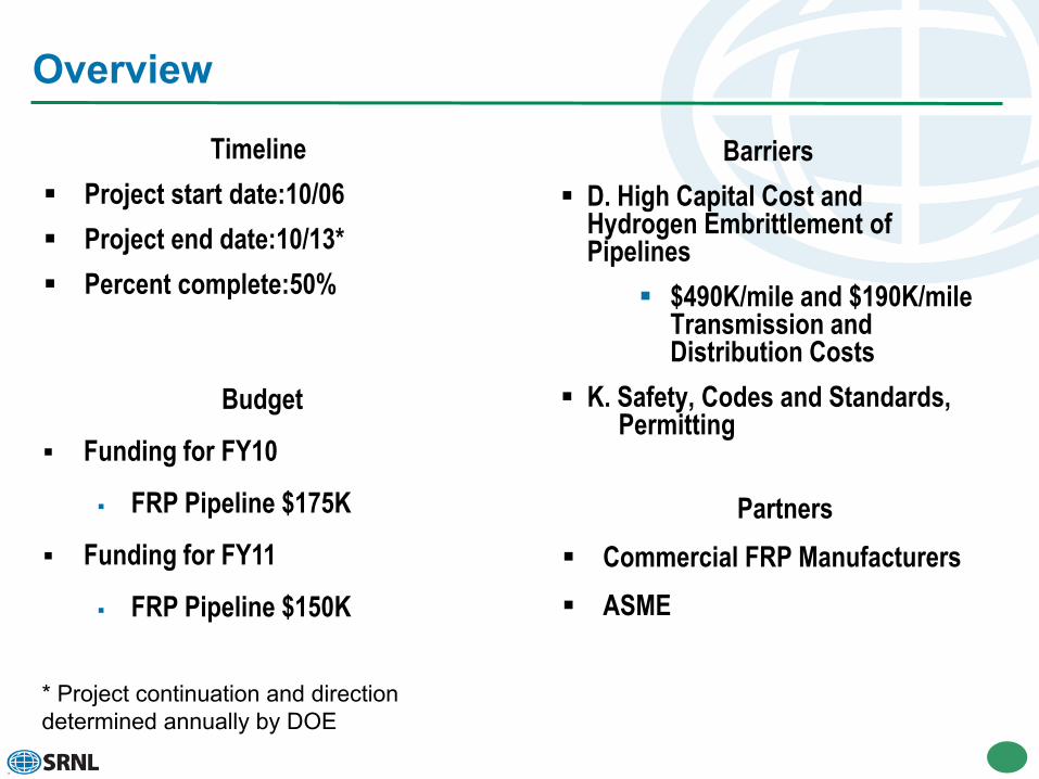
Timeline Project start date:10/06 Project end date:10/13* Percent complete:50%
Barriers D. High Capital Cost and
Hydrogen Embrittlement of Pipelines
$490K/mile and $190K/mile Transmission and Distribution Costs
K. Safety, Codes and Standards, Permitting
Budget
Funding for FY10
FRP Pipeline $175K
Funding for FY11
FRP Pipeline $150K
Partners Commercial FRP Manufacturers ASME
* Project continuation and direction determined annually by DOE

Relevance –2010 DOE Technical Targets
Hydrogen Pipeline Delivery Targets
Target Units 2017Pipeline : Transmission $/mile $490,000
Pipeline : Distribution $/mile $190,000
Reliability/Integrity Acceptable for H2 as Energy Carrier (2017)
Η2 Leakage <0.5% (2017)
“Develop hydrogen fuel delivery technologies that enable the introduction and long long-term viability of hydrogen as an energy carrier for transportationand stationary power”
-DOE Hydrogen Delivery Goal

Relevance –Objectives
Overall Project Scope: Development of Technical Basis for Life Management/Structural Integrity Methodology for
Fiber Reinforced Composite Pipeline Materials Environmental Effects Flaw Tolerance Testing Joint Integrity
Challenges: Reduced Installation Costs for FRP is an Attractive Attribute—One that Offers the
Potential to Meet the Long Range (2017) Cost Targets for Installed Hydrogen Delivery Pipeline—Critical Issues That Need to be Addressed are as Follows: FRP Liner Hydrogen Embrittlement Susceptibility, FRP Liner Hydrogen Permeation, Qualification of Joint/Joint Components, and External Damage Robustness
Targets: Implement Life Management Methodology Development Initiate Codification of FRP for Hydrogen Pipeline Service

Baseline Approach to Hydrogen Delivery
At Greater Than 5-10% Market Penetration in a Hydrogen EconomyHydrogen Delivery via Pipelines Becomes the Most Economical Option

Key Challenges for H2 Delivery
Key Challenges
Retro-fitting existing NG pipeline for hydrogen Utilizing existing NG pipeline for Mixed Gas Service New hydrogen pipeline: lower capital cost Leakage/Seals/Permeation Hydrogen Effects on Materials Lower cost and more energy efficient compression technology Lower cost and more energy efficient liquefaction technology Novel solid or liquid carriers

Comparison of Materials Options
Metallic Pipeline MaterialsCarbon steel systems operating in hydrogen service with no history of failure that can be attributed to any of these factors. Generally the materials are low strength alloys.
Challenges for Carbon and low alloy steel :Affected by dry hydrogen gas serviceShow reduction in ductility, fatigue strength, burst strengthCould be subject to sustained load cracking
Existing Technology Issues:Gaps in comprehensive material test data for carbon steel in a high pressure hydrogen environment. Additional design conservatism is utilized to account for these gapsReduce conservatism may be possible when comprehensive test data is availableReduce Installation Cost Paramount for Meeting DOE Cost Targets
Fiber Reinforced CompositeComposite pipeline technology has the potential to reduce installation costs, improve reliability and provide safer operation of hydrogen pipelines.
Advantages to using FRP:Excellent burst and collapse pressure ratings Large tensile and compression strengthsSuperior chemical and corrosion resistance Long lengths can be spooled for deliveryA few workers can install thousands of feet of pipeline per day
Existing Technology:FRP is an existing commercial technology currently employed in the oil & gas business—commercial product up to 4” diameter and 1500psig pressure rating

Approximately 20-60% Cost Reduction for FRP vs Welded Steel Construction
Economic Case StudiesEconomic Advantage: Single Wrap Case Study2.5 mile Gathering Line
Buried, Low Pressure
Welded Carbon Steel ConstructionWelded 2” Steel Line= $7/ft—labor, trenching, etc..Welded 2” Steel= $2.95/ft—materials cost
Single Wrap—4000ft Spool 1.75” IDLabor Cost—trenching, connections, etc..=$2/ftMaterials Cost=$2/ft
.
Multi-Wrap Installed Cost 80% of Steel
• 1.5 Miles of 2.5” Flowline Installed and Operating in 8-hours
• 3.0 Miles of Saltwater Line Installed and Operating in 2.5 Days
3547
0 09 4 5
60
1710 7
0 4 20
10
20
30
40
50
60
Material Construction Deployment End Fittings Coatings Risers Inspection
Fiberspar vs Steel Pipeline
FibersparSteel
Frac
tion
of In
stall
ed C
ost

SRNL in collaboration with ASME has developed an FRP Life Management Plan
Detail investigation is needed in the following areas:
System Design and Applicable Codes and Standards
Service Degradation of FRP
Flaw Tolerance and Flaw Detection
Integrity Management Plan
Leak Detection and Operational Controls Evaluation
Repair Evaluation
FRP Life Management

Design Margin for FRP
Stress ratios are being set innewer standards to address reliability in regards to stress rupture as compared with theHydrostatic Design Basis used in ASTM D2992.
The date provided by Robinson,Aerospace Corporation has shown that a margin of 3.5 on the burstpressure (.28 Stress Ratio) will provide a creep rupture life of 25 years.
Burst data for FRP Design to ASTMD2292 indicated that the margin on burst of 4.0 indicating that there isadditional margin to address factors like third party damage, environment and additional service.
Robinson Aerospace Corporation

Experimental Testing
Flaw Tolerance Testing40% Through Wall1-2” length0.125-0.25 “ width
Environmental Exposure Flaw Testing40% Through Wall1” length0.125” widthExposure to pH 2.4 and 11.6@ 120 hrs
Sustained Pressure Dimensional Stability1500psig ( max rated pipe pressure)
Joint LeakageBending MomentCyclic Load

Fiber Reinforced Composite Pipeline
FRP Burst Data
0
1000
2000
3000
4000
5000
6000
7000
0 5 10 15 20 25 30 35 40 45
Flaw Depth (%)
Burst
Pres
sure
(psi)
Baseline 0.125 X 1"
Additional Baseline @ 40 % Depth
Exposed 11.6 PH 120 Hr
Exposed 2.4 PH 120 Hr
2 X Length 0.125" X 1"
2 X Width 0.25" X 1"
Evaluation of Third Party Damage Multi - Layer Reinforcement
40% Through Wall Flaws
0
1000
2000
3000
4000
5000
6000
1 2 3 4 5 6 7 8 9
Samlple
Bur
st P
ress
ure
(psi
)

Fiber Reinforced Composite Pipeline
Reduction in Burst Pressure from unflawed condition to 40% through wall flaw of 28 % for short term burst and multiply layer reinforcement
With the 40 % through wall flaw there is still a margin of approximately 3 above the rated pressure
Evaluation of Third Party Damage
Multi - Layer Reinforcement
Failure mode changes from global to local and then move back towards global as flaw depth increases
2 X Length 2”x 0.125
40% Depth
2 X Width 1”x 0.25
40% Depth
Baseline Flaw
Width 1”x 0.125
40% Depth

Fiber Reinforced Composite Pipeline Evaluation of Third Party Damage Multi - Layer Reinforcement
Baseline Flaw
1”x 0.125
40% Depth
Additional Baseline Flaw
1”x 0.125
40% Depth
0
1000
2000
3000
4000
5000
6000
1 2 3 4 5
Sample
Bur
st P
ress
ure
(psi
)
Pipe Diameter Measurement
2.202.252.302.352.402.452.502.55
0 24 48 72 96 120 144
Hours
Dia
met
er (i
n)
No Evidence of Bulging Under Sustained Pressure

Chemical Exposure Tensile Strength Results
The API 15HR Specification for High Pressure Fiberglass Line Pipe indicates the need to address an environmental service factor. But does not provide a methodology. A performance test as applied in pressure vessel
standards may be a better option
1”x 0.25
40% Depth
PH 11.6 120 Hr
1”x 0.25
40% Depth
PH 2.4 120 Hr
4400
4450
4500
4550
4600
4650
4700
4750
4800
4850
Base Line PH 11.6 PH 2.4
Sample
Bur
st P
ress
ure
(psi
)
Single Strand Data
0
2500
5000
7500
10000
12500
15000
17500
20000
22500
25000
0.0 0.5 1.0 1.5 2.0 2.5 3.0 3.5
Strain [%]
Str
es
s [
ks
i]
E_Glass_pH2.4_24hr
E_Glass_pH2.4_120hr
E_Glass_pH7.0_24hr
E_Glass_pH7.0_120hr
E_Glass_pH11.6_24hr
E_Glass_pH11.6_120hr
S_Glass_pH2.4_24hr
S_Glass_pH2.4_120hr
S_Glass_pH7.0_24hr
S_Glass_pH7.0_120hr
S_Glass_pH11.6_24hr
S_Glass_pH11.6_120hr
S-Glass E-Glass

Fiber Reinforced Composite Pipeline Leak Testing
• NASA Report NSS- 1740.16 Pressure boundary rupture only make up 14 percent of the hydrogen accidents. Accidents due to leakage and improper handling of hydrogen make up a greater percentage of the accident.
Sample
Leak Rate
STD CC H2/Sec
Fiber 1 4.08X10⁻⁵
Poly 1 5.5X10⁻²
Physical Leak Permeation Leak
Performed Hydrogen Leak Testing Measurements Using H2 @ 1000 psi Sensitivity of 10-9 cc/sec
Polyflow™ HydraulicallyCrimped Joints Components
Fiberspar™ ThreadedCompression Joints Components

Fiber Reinforced Composite Pipeline Leak Testing• DOT Gap Analysis Report Identifies 4
Major Needs for Composite FRP Piping
• Lack of Design Specifications
• Qualified Joints/Joining
• Permeation
• Robustness to External Damage
• Performed Hydrogen Leak Testing Measurements Using H2 @ 1000 psi Sensitivity of 10-5-10-6 cc/sec
Fiberspar™ ThreadedCompression Joints Components
Polyflow™ HydraulicallyCrimped Joints Components
Sample Leak Rate
STD CC H2/Sec
Fiber 1 9.8x10⁻⁵
Poly 1 9.5x10⁻³
Poly 1+ 5.0x10⁻²
Standard Code Leak Testing Evaluates Leaks Rates on the Order of 10-2-10-4cc/sec of the fluid

Fiber Reinforced Composite Pipeline Test Under Applied Bending Load
• DOT Gap Analysis Report Identifies 4 Major Needs for Composite FRP Piping
• Lack of Design Specifications
• Qualified Joints/Joining
• Permeation
• Robustness to External Damage
• Performed Hydrogen Leak Testing Measurements Using H2 @ 1000 Psi Sensitivity of 10-5-10-6 cc/sec
• Loaded in 3 Point Bending--2 Inch Displacement
Sample
Leak Rate
STD CC H2/Sec
Fiber 1 1.4x10⁻⁴
Poly 1 Cycled
8.9x10⁻⁴
Poly 1+ 8.1x10⁻⁴
Fiberspar™ ThreadedCompression Joints Components
Polyflow™ HydraulicallyCrimped Joints Components

FRP Hydrogen Pipeline Demonstration FacilitySchematic of FRP Hydrogen Pipeline Demonstration Facility
Proposed FRP Hydrogen Demonstration Loop between DOE, State of South Carolina
Partners DOE, State of South Carolina, Aiken Country SRNL, ORNL, and ASME
Workshop being planned for the summer 2012 to discuss path forward.
CHR
FUTURE ELECTROLYZER REFORMER FURTURE
RENEWABLE
H2 GENERATION
Test Module
Test Loop H2 Pipeline
Future Storage
Tank
CHR – Center for Hydrogen Research
Test Module Test Module
CHR
FUTURE ELECTROLYZER REFORMER FURTURE
RENEWABLE
H2 GENERATION
Test Module
Test Loop H2 Pipeline
Future Storage
Tank
CHR – Center for Hydrogen Research
Test Module Test Module

Summary
FRP is an Attractive Technology with Potential to Reduce Overall Pipeline Installation Cost
Field Case Studies Indicate 20-60% Reduced Cost Over Steel Pipeline FRP Pipe Fabricated API 15HR is the most relevant Standard reviewed to date for the
fabrication of FRP line pipe for hydrogen service. This standard can be tailored to address the need for hydrogen pipelines
Flaw tolerance tests show that for flaws up 40% through-reinforcement and up to 2 “ length and 0.25” width a factor of 3X margin is maintained on rated pressure
Performance testing to evaluate both flaw tolerance and environmental effects has been conducted—integrated test better indicator of performance over previous testing of individual materials test
The current recommendation is to develop a performance based design specification to be included in ASME B31.12
Workshop to Discuss Next Steps Toward ASME Codification to be Held in FY11

Proposed Future Work –FY11-12 SRNL Scope for FRP
Perform long term stress rupture test for flawed FRP samples
Performed additional burst testing of flawed FRP samples on aged samples
Recommend performance qualification tests for FRP in H2 service to ASME B31.12 Committee
Evaluate B31.8S (Managing System Integrity of Gas Pipelines) for changes needed to address FRP in H2 service;
Workshop with State of SC, ASME B31.12, and Key Technical Resources to Outline Plan for Inclusion of FRP in B31.12 Code