fiber-optic accelerometer using wavefront-splitting interferometry hsien-chi yeh & shulian zhang...
TRANSCRIPT
Fiber-Optic Accelerometer Fiber-Optic Accelerometer Using Wavefront-Splitting Using Wavefront-Splitting
InterferometryInterferometry
Hsien-Chi Yeh & Shulian ZhangHsien-Chi Yeh & Shulian Zhang
July 14, 2006July 14, 2006
OutlineOutline Working PrincipleWorking Principle Design of AccelerometerDesign of Accelerometer Preliminary ResultsPreliminary Results Conclusion & DiscussionConclusion & Discussion
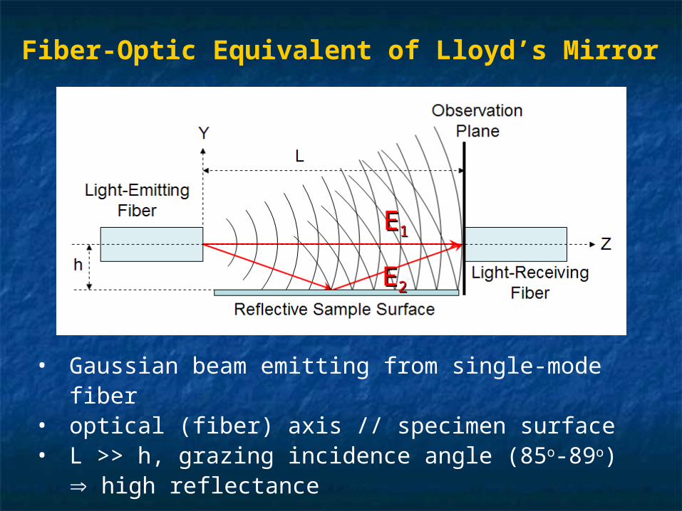
• Gaussian beam emitting from single-mode fiber• optical (fiber) axis // specimen surface• L >> h, grazing incidence angle (85o-89o)
high reflectance
Fiber-Optic Equivalent of Lloyd’s Mirror
EE11
EE22
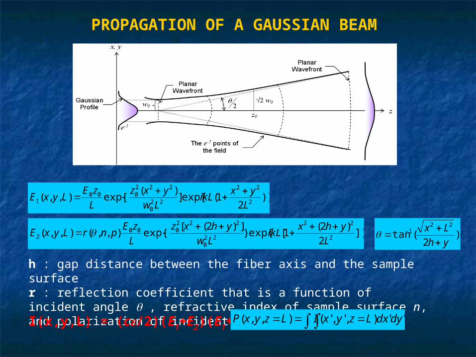
PROPAGATION OF A GAUSSIAN BEAM
)]2
1(exp[])(
exp[),,(2
22
220
222000
1 L
yxikL
Lw
yxz
L
zELyxE
]}2
)2(1[exp{}
])2([exp{),,(),,(
2
22
220
222000
2 L
yhxikL
Lw
yhxz
L
zEpnrLyxE
)
2(tan
221
yh
Lx
h : gap distance between the fiber axis and the sample surfacer : reflection coefficient that is a function of incident angle , refractive index of sample surface n, and polarization of incident light p
I(x,y,L) = (c/2)(E1+E2)(E1+E2)* ''),','(),,( dydxLzyxILzyxP
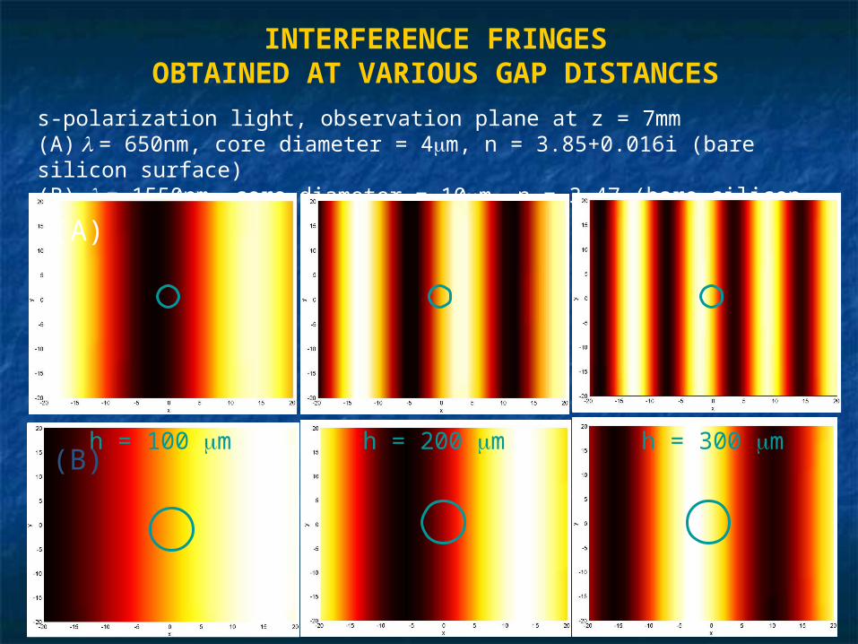
s-polarization light, observation plane at z = 7mm(A) = 650nm, core diameter = 4m, n = 3.85+0.016i (bare silicon surface)(B) = 1550nm, core diameter = 10m, n = 3.47 (bare silicon surface)
h = 100 m h = 200 m h = 300 m
(A)
(B)
INTERFERENCE FRINGESOBTAINED AT VARIOUS GAP DISTANCES
100 120 140 160 180 2000
50
100
150
200
250
300
350
gap distance between the sensor and the sample surface (um)
optic
al o
utp
ut (
pW)
p-polarizations-polarization
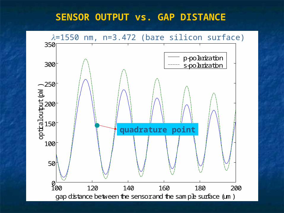
=1550 nm, n=3.472 (bare silicon surface)
SENSOR OUTPUT vs. GAP DISTANCE
quadrature point

Design of Design of Accelerometer Accelerometer
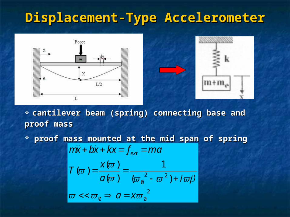
Displacement-Type AccelerometerDisplacement-Type Accelerometer
cantilever beam (spring) connecting base and cantilever beam (spring) connecting base and
proof massproof mass
proof mass mounted at the mid span of springproof mass mounted at the mid span of spring
200
220 )(
1
)(
)()(
xa
ia
xT
mafkxxbxm ext
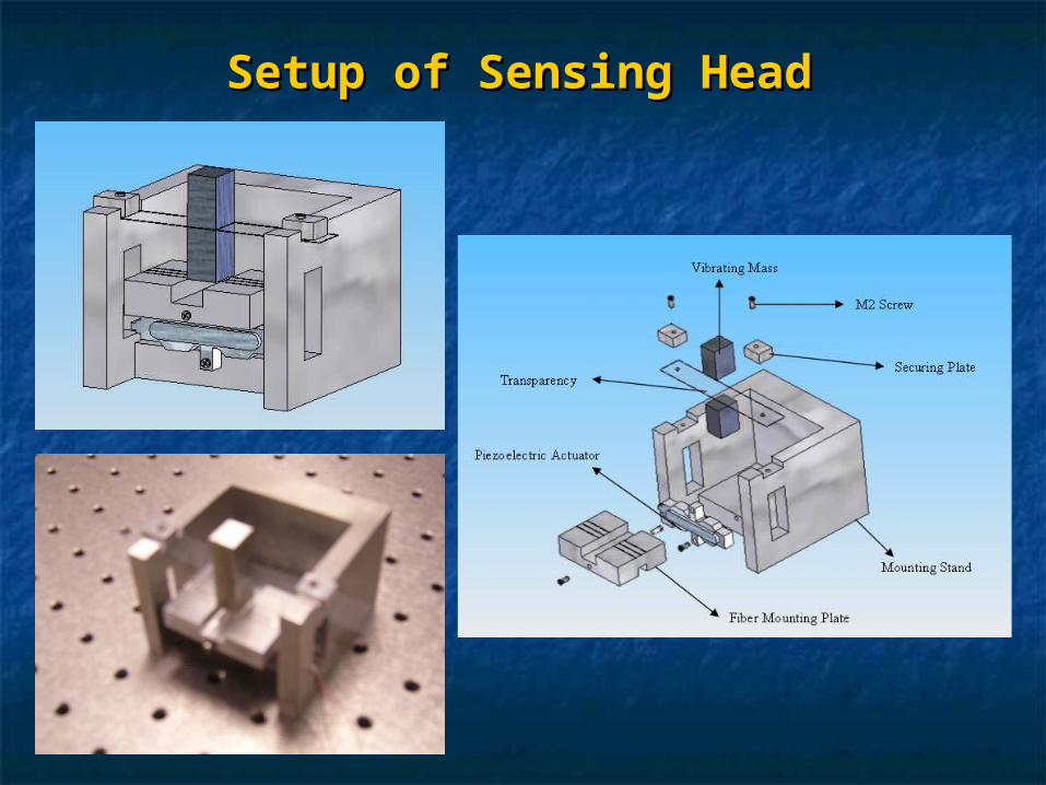
Setup of Sensing HeadSetup of Sensing Head

Fiber Mounting Fiber Mounting
PlatePlate
Aluminum used: Cost effective, fast machiningAluminum used: Cost effective, fast machining
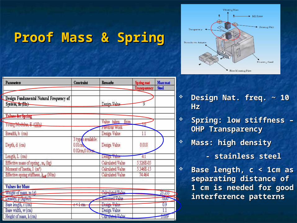
Proof Mass & SpringProof Mass & Spring
Design Nat. freq. ~ 10 Design Nat. freq. ~ 10 HzHz
Spring: low stiffness – Spring: low stiffness – OHP TransparencyOHP Transparency
Mass: high density Mass: high density
- stainless steel - stainless steel
Base length, c < 1cm as Base length, c < 1cm as separating distance of 1 separating distance of 1 cm is needed for good cm is needed for good interference patternsinterference patterns
Preliminary Tests Preliminary Tests
Resonance frequencyResonance frequency Seismic test on optical tableSeismic test on optical table Seismic test on workbench Seismic test on workbench
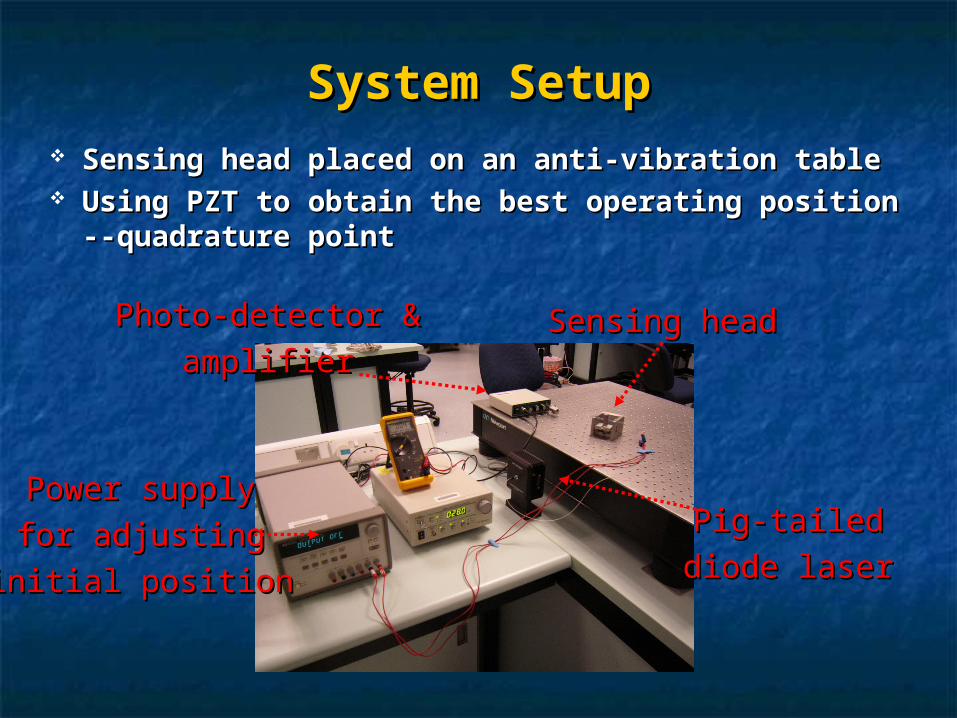
System SetupSystem Setup Sensing head placed on an anti-vibration tableSensing head placed on an anti-vibration table Using PZT to obtain the best operating Using PZT to obtain the best operating
position --quadrature pointposition --quadrature point
Sensing headSensing head
Pig-tailedPig-tailed
diode laserdiode laser
Photo-detector &Photo-detector &
amplifieramplifier
Power supplyPower supply
for adjustingfor adjusting
initial positioninitial position
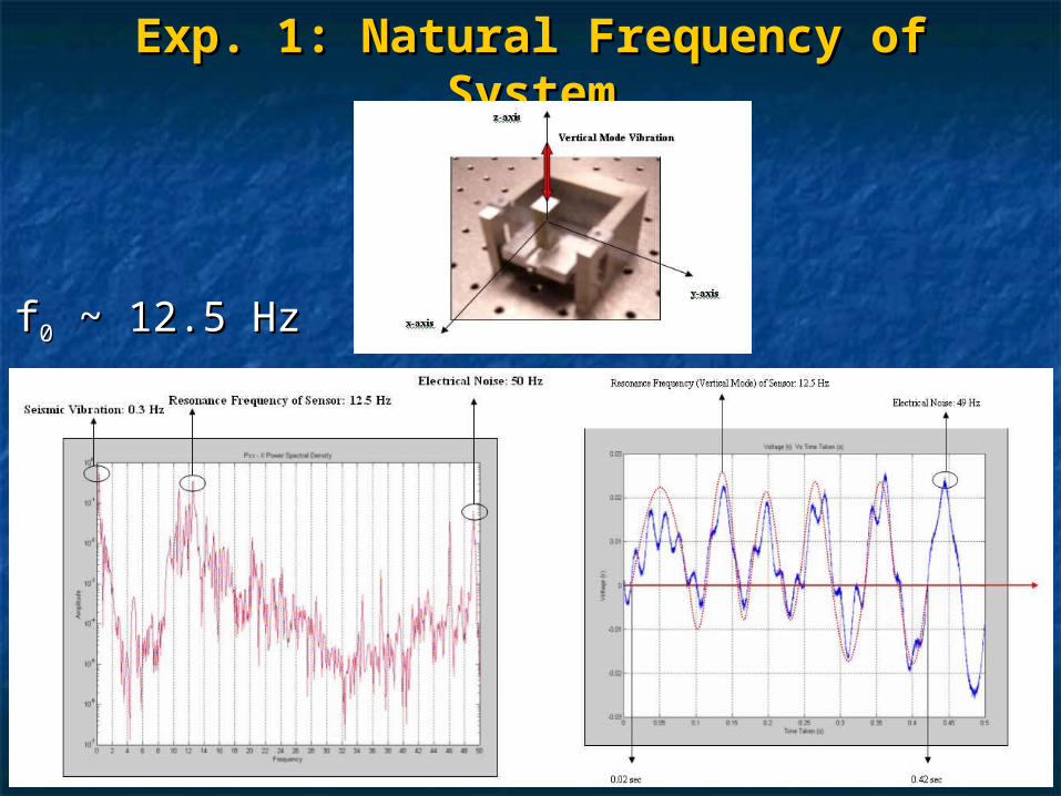
Exp. 1: Natural Frequency of Exp. 1: Natural Frequency of SystemSystem
ff00 ~ 12.5 Hz ~ 12.5 Hz
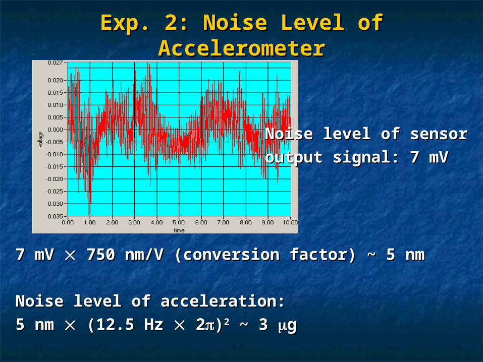
Exp. 2: Noise Level of Exp. 2: Noise Level of AccelerometerAccelerometer
Noise level of sensorNoise level of sensor
output signal: 7 mVoutput signal: 7 mV
7 mV 7 mV 750 nm/V (conversion factor) ~ 5 nm 750 nm/V (conversion factor) ~ 5 nm
Noise level of acceleration:Noise level of acceleration:
5 nm 5 nm (12.5 Hz (12.5 Hz 2 2))22 ~ 3 ~ 3 gg
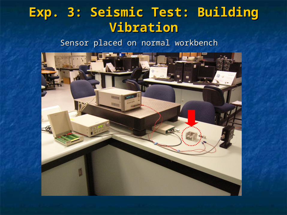
Exp. 3: Seismic Test: Building Exp. 3: Seismic Test: Building VibrationVibration
Sensor placed on normal workbenchSensor placed on normal workbench
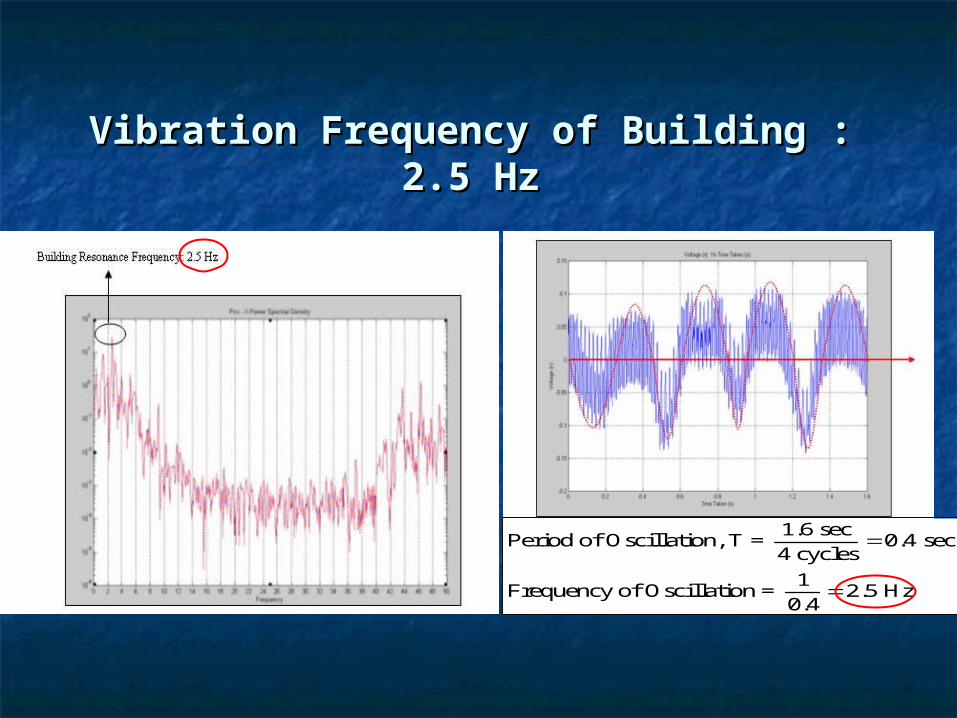
Vibration Frequency of Building : 2.5 Vibration Frequency of Building : 2.5 HzHz
1.6 secPeriod of Oscillation, T = 0.4 sec
4 cycles
1Frequency of Oscillation = 2.5 Hz
0.4
Discussion & ConclusionDiscussion & Conclusion
Prototype of fiber-optic accelerometer based Prototype of fiber-optic accelerometer based on wavefront-splitting interferometryon wavefront-splitting interferometry
Operating range: DC-24 HzOperating range: DC-24 Hz Resolution: < 3 Resolution: < 3 gg Further improvementsFurther improvements
Finding suitable material for spring to achieve Finding suitable material for spring to achieve lower resonance frequency and optimal damping lower resonance frequency and optimal damping coefficientcoefficient
Reducing the size of sensing head to obtain larger Reducing the size of sensing head to obtain larger signal-to-noise ratiosignal-to-noise ratio
Closed-loop feedback control to achieve null-Closed-loop feedback control to achieve null-sensing capabilitysensing capability

Thank YouThank Youfor your attentions!for your attentions!