fiber gyroscope principles - università di pavia of fibre optic sensing technology, edited by josé...
TRANSCRIPT

Handbook of Fibre Optic Sensing Technology, edited by José Miguel López-Higuera ISBN-X-XXX-XXXXX-X 2000 John Wiley & Sons Ltd.
FIBER GYROSCOPE PRINCIPLES SABINA MERLO, MICHELE NORGIA and SILVANO DONATI
Electrooptics Group University of Pavia, Italy
Abstract After a brief review of the milestones leading to the development of the optical gyroscope, we describe the basic principles underlying the Fiber Optic Gyroscope and discuss optical configurations, readout techniques and performance limits of this device. A final comment on prospects of developments is presented.
16.1 Introduction The idea of using a laser interferometer to read the Sagnac phase shift in a closed-cavity path can be traced back to the very early time of the laser history, and is one of the proposals soon recognized as very promising for the application of lasers to avionic instrumentation - namely, inertial navigation platforms. Indeed the He-Ne laser, ideally suited for interferometry, was discovered in 1961 and just a year later Macek and Davis reported [1] about the detection of earth-rotation Sagnac-effect in a 1-m side square-cavity built around He-Ne tubes.
In spite of this initial spurt, progresses in the development of a device really working in the field have been slow, and the road of engineering out of the laboratory prototype has been paved with obstacles, not only technological but also conceptual. It took fifteen years of efforts by the international scientific community, totalling several thousands of man-years work, reflected by hundreds of papers in Journals, to circumvent a number of problems - first of all the locking of the modes already highlighted by the early experiments - which seemed to prevent the gyro from reaching the small-rotations range, the one of utmost interest for applications [2]. Also, a substantial technological effort has been devoted to obtain cavities in very-low thermal expansion materials as required for frequency stabilization, and to make

2 HANDBOOK OF FIBRE OPTIC SENSING TECHNOLOGY
interference layers of exceptionally-low scattering (~10-5), as necessary for the cavity mirrors. Thus, around the mid’70s years, the laser (or, ring-laser) gyro (RLG) finally reached the
status of the fully understood, producible and high-performance device as we know it today. Undoubtedly, the RLG has been the first unquestionable success of laser and electrooptics, and entered the mass-production stage being incorporated, since the ‘80s, in all the new-designed military and civilian aircrafts as the sensor of inertial navigation units (INU) and heading attitude reference systems (HARS). Billings of RLG’s have since then reached a steady level in the range of 1000 million US$ per year.
When, all of a sudden, in 1976 a new approach was proposed by Vali and Shorthill [3], the fiber gyroscope or fiberoptic gyro (FOG) which took to advantage the newly developed single-mode fibers as the propagation medium. At that time, the hint was to improve sensitivity through increasing the cavity length substantially, and hence the Sagnac signal. The FOG arouse interest because of the modular structure and the much easier fabrication and scalability (and hence, a potential lower cost). The FOG too was starting from performances far away from those of interest for applications, yet a decade of efforts by international research groups has led to a fairly established device, though not completely attaining the projected sensitivities. Progresses were about technology, with the development of specialty fibers (the polarization maintaining or hi-bi fiber) and passive and integrated-optics components (couplers, phase modulators), but also and dramatically, about the optical circuit configurations (with the concept of reciprocity first clarified by Ulrich [4]), and the readout schemes (open-loop vs. closed-loop, serrodyne, etc.) [5-7].
By the mid 80’s years, the FOG has finally reached its engineering maturity and has been deployed in the field in industrial quantities, though much smaller than the RLG, despite the lower sensitivity (typ. ~0.1 °/hour) that still unrivals the RLG sensitivity (down to ~0.001 °/hour). The reason of success includes some desirable features like lightweight, size, limited power consumption, projected long lifetime and, not least, cheaper price.
Thus, rather than competitive, the FOG and the RLG are complementary approaches and devices finding their own application, as depicted in Figure 16.1 where the two most important parameter relevant to technical performances, i.e., sensitivity and dynamic range, are plotted in a diagram describing a number of typical gyro applications.
Nowadays, the research effort on gyros is not fading out: new segments of application such as the automotive and the robotics call for less demanding performances than in avionics but drastically reduced cost and overall size.
On one hand, efforts have been pursued to push the FOG into the new shape through, e.g., the 3x3 or minimum-part-count and the resonant configurations; on the other hand, new promising approaches have been devised like, e.g., the IO (integrated optics) in either SOS (silica-on-silicon, FOG-type) technology [8] or in GaAs (RLG-type) [9], and the MEMS (micro-electro-mechanical-system) gyro [10], a refurbishment of the old concept of spinning-mass gyros that the RLG had made obsolete.
16.2 The basic gyroscope scheme and the Sagnac effect The electrooptic gyroscope [11-16] is a highly sensitive optical interferometer for the very

FIBER GYROSCOPE PRINCIPLES
3
0.0 0 1 1
1 00 0
1 00
1 0
DY
NA
MIC
RA
NG
E (°
/s)
0 .1 0 .0 1 1 0 1 00 1 0 0 0
spa ce navi- ga tion
se nsorshorizon
ICBM
miss ile s
airpla nes
RLG
ta ctica lmiss ile s
oildrilling
robotics
G-A RADARS
s pin s ta bilize d m is s ile s
a utomotive
FOG MEMS, IO gyros
SENSITIVITY (°/h) Figure 16.1 Application areas and performances of the RLG and FOG gyroscopes (full lines), and projected performance for MEMS and Integrated-Optics gyroscopes (dotted line).
high resolution readout of the Sagnac phase shift [17] induced between two counterpropagating waves in an optical closed path when the plane of propagation undergoes angular rotation [18-19].
Important to note, the phase measurement must include the DC term and requires a sensitivity of about 10-6 rad (or 10-12 m in path-length) on a total path-length of some 102 m: the 10-14 resolution of the gyro is a quite a record of performance in sensors and is the reason why the readout as well as each component of the gyro must be very carefully designed.
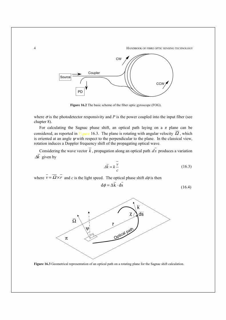
The basic scheme of the interferometric fiber optic gyroscope (IFOG) is illustrated in Figure 16.2. It is a passive interferometer where the fiber optic coupler is employed to split the radiation from the light source into two counterpropagating waves, clockwise (CW) and counterclockwise (CCW), in the fiber coil and to recombine the waves, after propagation, on a photodetector PD [3,20].
The phase difference is thus cumulated over a long fiber coil for obtaining high responsivity with a compact device. For ideal fibers and components, the output photogenerated current I has the following expression:
I=I0(1-cosφS) (16.1) where φS is the so called Sagnac phase shift and
2PσI0 =
(16.2)
4 HANDBOOK OF FIBRE OPTIC SENSING TECHNOLOGY
Coupler
CW
CCW
Source
PD
Figure 16.2 The basic scheme of the fiber optic gyroscope (FOG).
where σ is the photodetector responsivity and P is the power coupled into the input fiber (see chapter 8). For calculating the Sagnac phase shift, an optical path laying on a π plane can be considered, as reported in Figure 16.3. The plane is rotating with angular velocity Ω , which is oriented at an angle ψ with respect to the perpendicular to the plane. In the classical view, rotation induces a Doppler frequency shift of the propagating optical wave.
Considering the wave vector k , propagation along an optical path sd produces a variation k∆ given by
cvkk∆ =
(16.3)
where rv ×= Ω and c is the light speed. The optical phase shift dφ is then
sdk∆d ⋅=φ (16.4)
π
Ωψ
χ
r
k
Optical path
ds
Figure 16.3 Geometrical representation of an optical path on a rotating plane for the Sagnac shift calculation.
FIBER GYROSCOPE PRINCIPLES
5
Substituting Equation 16.3 into Equation 16.4 yields
[ ]cksdrΩd ⋅×=φ (16.5)
By expliciting the products in Equation 16.5 (see Figure 16.3) it becomes:
ds rsinχ Ωcosψ
ckd
=φ (16.6)
Integration of Equation 16.6 along the whole optical closed path gives the total optical phase shift ∆φ
2AN Ωcosψ
ck∆
=φ (16.7)
since 2ANds rsinχ = where A is the area enclosed by the optical path and N is the number of turns. The Sagnac phase shift φS is the phase shift difference between two counterpropagating waves along the same optical path, so that φS=2∆φ. By recalling that k=2π/λ, where λ= is the wavelength, the well known equation of the optical gyroscope can be finally obtained
λc
ANΩ8 pS
πφ = (16.8)
which states that the Sagnac phase shift depends on Ωp =Ω=cosψ, the component of the angular velocity perpendicular to the plane of the optical path. For the FOG, N is the number of loops of the fiber coil and A is the area enclosed by each fiber loop. Equation (16.8) is correct if λ is the vacuum wavelength, while classically the wavelength in the propagation medium should be expected. Reason for discrepancy is that the simple Doppler-effect description is not correct, because the observer is accelerated, and special relativity is required [21]. An alternative very simple analysis [22], rigorous from the relativistic point of view, starts from a lossless, totally reflecting, toroidal, vacuum cavity where two counterpropagating waves form a standing wave with a λ/2 period, as shown in Figure 16.4. Since there is no energy exchange between the cavity and the travelling waves, the generated standing wave is not affected by the angular rotation Ωp of the cavity. For the observer (detector) rotating with the cavity, the standing wave seems moving with a ΩpR velocity, which is equivalent to observe a frequency difference ∆f between the counterpropagating waves given by
∆f = 2 Ωp= λR
(16.9)
Recalling that, because of the resonance in the cavity, every c/p of frequency increase corresponds to a 2π increase in the optical phase shift, the Sagnac phase shift φS can be written as:
cpfs ∆=
πφ2
(16.10)

6 HANDBOOK OF FIBRE OPTIC SENSING TECHNOLOGY
Ω
Detector
λ/2
R
Figure 16.4 Standing waves in toroidal cavity rotating with the detector.
where p=2 π R is the perimeter, and thus φS is given by:
cA p
s λπ
φΩ
=8
(16.11)
which coincides with Equation 16.8 for N=1. The relativistic analysis states that Equation 16.11 is correct when the detector is rotating
with the gyroscope, while if only the gyroscope - or only the detector is moving, Equation 16.11 needs to be multiplied by n2 - or (n2-1), respectively-, where n is the propagation medium refractive index [23]. Thus, in the practical case of a FOG fiber-path rotating while the observer is still, the new n2 term cancels out with the n2 coming from the factor λc, and Equation 16.8 is therefore valid also for a propagation medium with n≠1. The Sagnac phase shift as a function of the angular rotation Ωp is reported in Figure 16.5 for different values of the total enclosed area AN. With a typical FOG (200 m-long fiber wounded on a 10 cm-diameter coil) the measurement of the earth angular rotation Ωe=15 °/h= 0.73 µr/s requires to detect a phase difference φS=36 µr, corresponding to an optical path difference of the order of 10-12 m. As already pointed out, this measurement is to be performed in DC and thus it is considerably more difficult than the measurement of a tiny vibration in AC.
16.3 Limit of performances Considering the phase signal detected by the FOG (Equation 16.1), the phase noise φn at
the quantum limit is equal to the inverse of the amplitude signal to noise ratio (SNR) [20], calculated at a bias point φSb=π/2. Considering the signal current I0 and the related shot noise current B2eII oshot = , where B is the measuring bandwidth and e is the electron charge, the

FIBER GYROSCOPE PRINCIPLES
7
10-6
10-7 10-5 10-3 10-1
Angular velocity Ω (r/s)
Sagn
ac p
hase
shi
ft (r)
10-4
10-2
100
10-8
Optical path variation
1pm
1fm
1nm
AN=100 m2
10 m
2
1 m2 0.1
m2
0.01 m
2
Figure 16.5 The Sagnac phase shift as a function of the angular velocity Ωp for different values of the total enclosed area AN (λ=850 nm). Thick line is for typical values of the FOG.
phase noise is
oo
shotn I
2eBI
I==φ (16.12)
which can be stated alternatively as
0n P
2hfB=φ
(16.13)
since
η·PhfeI 0o = (16.14)
where h is the Planck’s constant, f=c/λ , P0 is the equivalent detected power and η is the quantum efficiency of the photodetector.
The phase noise at the quantum limit corresponds to a noise equivalent rotation rate NEΩ given by
ηπ ·P
2hfBAN8λcNEΩ
0= (16.15)
The phase noise at the quantum limit as a function of B is reported in Figure 16.6, with the equivalent detected power P0 as a parameter. For example, for B=1 Hz and P0=0.1 mW, the

8 HANDBOOK OF FIBRE OPTIC SENSING TECHNOLOGY
10-7
1 102 104 106
Bandwidth B (Hz)
Phas
e N
oise
φn (
r)10-5
10-3
10-9
10-5 W10-4 W
10-3 W10-2 W
10-1 W 1 W
10 W
Figure 16.6 The phase noise at the quantum limit as a function of B, with the equivalent detected power Po as a parameter (λ=850 nm).
phase noise is φn =5·10-8 r corresponding to a minimum detectable angular velocity NEΩ== 0.007 °/h = 34·10-9 r/s, a very good value which is however, unfortunately, not attained in practice.
There are several non-idealities preventing the FOG from reaching the ultimate quantum-noise limit, all studied in details but none explaining the observed data.
We will comment on them in the following, while discussing the individual components and readouts of the gyro.
For what concerns the propagation medium, i.e., the fiber, phase noise due to thermodynamic fluctuations of the fiber refractive index and length has been investigated [24]. In a Sagnac configuration, however, this noise contribution becomes important only at relatively high input powers (say ~20 mW, for which φn~10-8 rad/√Hz) and is not therefore the dominant extra noise term.
16.4 Problems of development As first pointed out by Ulrich [4], to achieve a sensitivity which approaches the quantum
limit, it is required to eliminate all the sources of nonreciprocity, other than that induced by the Sagnac effect, in the propagation of the CW and CCW waves.
If the counterpropagating waves cumulate a nonreciprocal phase shifts due to optical components or ambient-induced disturbances, zero-point errors and fluctuations will occur and completely mask the Sagnac phase shift [25]. For example, significant errors are caused if the counterpropagating waves do not travel along the fiber with the same state of polarization and the same modal distribution. With regard to the polarization issue, in Figure 16.7 are
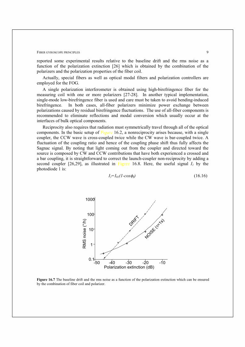
FIBER GYROSCOPE PRINCIPLES
9
reported some experimental results relative to the baseline drift and the rms noise as a function of the polarization extinction [26] which is obtained by the combination of the polarizers and the polarization properties of the fiber coil.
Actually, special fibers as well as optical modal filters and polarization controllers are employed for the FOG.
A single polarization interferometer is obtained using high-birefringence fiber for the measuring coil with one or more polarizers [27-28]. In another typical implementation, single-mode low-birefringence fiber is used and care must be taken to avoid bending-induced birefringence. In both cases, all-fiber polarizers minimize power exchange between polarizations caused by residual birefringence fluctuations. The use of all-fiber components is recommended to eliminate reflections and modal conversion which usually occur at the interfaces of bulk optical components. Reciprocity also requires that radiation must symmetrically travel through all of the optical components. In the basic setup of Figure 16.2, a nonreciprocity arises because, with a single coupler, the CCW wave is cross-coupled twice while the CW wave is bar-coupled twice. A fluctuation of the coupling ratio and hence of the coupling phase shift thus fully affects the Sagnac signal. By noting that light coming out from the coupler and directed toward the source is composed by CW and CCW contributions that have both experienced a crossed and a bar coupling, it is straightforward to correct the launch-coupler non-reciprocity by adding a second coupler [26,29], as illustrated in Figure 16.8. Here, the useful signal I1 by the photodiode 1 is:
I1=I01(1-cosφS) (16.16)
1000
100
10
1
0.1-50 -40 -30 -20 -10
*
*
*
+
*
+
+
+
DRIFT
NOISE (τ
=1s)
Polarization extinction (dB)
RM
S no
ise
(°/h
)
Figure 16.7 The baseline drift and the rms noise as a function of the polarization extinction which can be ensured by the combination of fiber coil and polarizer.

10 HANDBOOK OF FIBRE OPTIC SENSING TECHNOLOGY
Coupler
Coupler
CW
CCW
PD1
Source
PD2
Figure 16.8 The configuration with two couplers.
And the signal I2 from the photodiode 2 is given by
I2=I02(1+cosφS) (16.17) where the opposite signs of the beating term cosφS come out because of the phase shift introduced by the launch-coupler. Another source of errors is the backscattering [30-31], which induces a crosstalk between the CW and the CCW waves. In the FOG, scattering usually includes Rayleigh backscattering as well as backreflections at the interfaces.
This problem can be solved by using a light source with a very short coherence length [32], which prevents beating effects between the backscattered component and the copropagating wave. A superluminescent diode is thus the best choice for satisfying this requirement and for ensuring at the same time high coupling efficiency in the single-mode fiber. The magneto-optical Faraday effect, due, e.g. to electromagnetic interferences, is a nonreciprocal effect potentially dangerous in adding to the Sagnac effect [33-34]. This problem is now almost solved by the use of carefully untwisted polarization-maintaining fibers. Similarly, the nonreciprocity induced by the nonlinear Kerr effect [35] can be strongly reduced with broad-band, low-coherence, unpolarized optical sources or even with a simple 50% duty cycle modulation of the input optical power.
16.5 The open loop configuration with phase modulation A major problem of the basic configurations presented in Figures 16.2 and 16.8 is the
output nonlinearity for small φS≈0, which hinders high sensitivity measurements of small rotation angles without sign ambiguity. This limitation is overcome by transforming the baseband cosine-dependence into a sinusoidal function, for example, by translating the output signal from baseband to a carrier at angular frequency ωm. Although different solutions have been proposed and demonstrated, the optical phase modulation technique is nowadays commonly used. The typical setup of a practical FOG in all-fiber technology is reported in Figure 16.9, where a phase modulator is inserted in the fiber coil, close to a coupler output, so that a different phase delay is cumulated by the counterpropagating waves [16]. The all-fiber-version phase modulator is constructed by winding and cementing a few fiber turns on a short, hollow piezoceramic tube (PZT) [36]. By applying to the PZT a modulating voltage, a radial

FIBER GYROSCOPE PRINCIPLES
11
elastic stress and a consequent optical pathlength variation due to the elasto-optic effect are generated.
Fiber polarizer
PZTPhase modulator
Coupler
Coupler
CW
CCW
PD
Source
Figure 16.9 All-fiber gyroscope with phase modulator.
As a result, the CCW and the CW propagating waves experience a phase delay Φ(t) and
Φ(t + τ), respectively, where τ=L/v is the radiation transit time in the fiber of overall length L. The relative phase difference on the detector is then
=======ΦCCW - Φ CW = φS + Φ(t) - Φ(t + τ) (16.18)
which can also be written as ΦCCW - Φ CW = φS + Φ(t - τ/2) - Φ(t + τ/2) (16.19) Applying a phase modulation at angular frequency ωm Φ(t) = Φmo cos ωmt (16.20)
yields ΦCCW - Φ CW = φS + 2Φmosinωmτ/2 sinωmt = φs + Φmsinωmt (16.21)
where the amplitude Φm=2Φmo sinωmτ/2 can be maximized by selecting a PZT modulation frequency fm=ωm /2π=1/(2τ).
The photodetected signal I1 I1=I01[1+cos(ΦCCW - ΦCW)] (16.22)
is thus given by (using the Bessel's functions J)
( ) ( )
( ) ( ) sm1k
m12k
sm1k
m2kmoo
'
sintω12kcosΦJ2
costcos2kωΦJ2ΦJ1II
φ
φ
−+
+
++=
∞
=−
∞
= (16.23)
The photodetected signal contains, in addition to a DC components, all the harmonics of the modulating signal. The amplitude of the even harmonic components depends on cosφS, as in the basic scheme, while the odd components carry the desired sinφS dependence. The selection of Φm=1.8 maximize the J1(Φm) and the Sagnac phase shift with sign can be

12 HANDBOOK OF FIBRE OPTIC SENSING TECHNOLOGY
recovered with a lock-in amplifier by measuring the amplitude of the fm frequency component of the photodetected signal. The NEΩ at the quantum limit in this case becomes
( )
( )m1
mo
Φ2JΦJ1
ηP2hfB
8ππAλcNEΩ
+= (16.24)
With a typical fiber coil, taking the equivalent detected power P0=100 µW and Φm=1.8 yields
( ) ( )Hz
/h0.03Hz
µr/s0.14B
NEΩ °==
which should be compared to the laboratory sensitivity of 0.1 – 1°/h exhibited by initially developed fiber optic gyroscopes based on this approach.
16.6 Closed loop schemes with analog or digital phase ramp In the open loop configuration, the lock-in output signal V is given by V=V0sinφS (16.25)
where φS is given by Equation 16.8 and V0 is the fringe amplitude. A first problem of this signal is the intrinsic nonlinearity and limited dynamic range of the
sinusoidal function, which may represent a restriction in some applications. A second issue is related to the insufficient accuracy and stability of either the fringe amplitude and the scale factor which multiplies the rotation rate. The presence of only the analog output is also considered a third drawback of this configuration. A closed-loop scheme has been proposed with different implementations for solving most of the above mentioned problems. The basic idea consists in using a feedback effect which cancel the Sagnac phase shift by adding a controlled phase delay, thus directly proportional to the rotation rate to be detected. Since, as explained at the beginning of this chapter, the Sagnac effect can be envisioned as a Doppler effect, closed-loop operation was initially realized by generating a frequency shift using acusto-optic modulators [37]. This solution however was not the most appropriate in terms of maintaining reciprocity. Alternatively, the frequency variation is simulated by a phase ramp modulation, which has to be superimposed and synchronized to the biasing phase modulation previously described [38-41].
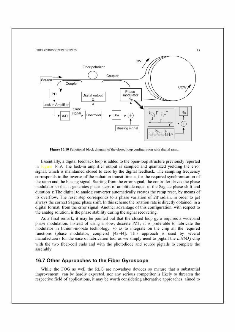
The analog solution, based on an analog phase ramp (also indicated as serrodyne modulation) in addition to the sinusoidal biasing modulation, does not represent a very efficient solution. A great improvement is obtained with the all-digital approach based on a square wave biasing modulation and on a digital phase ramp for closed-loop processing [42]. The functional block diagram of this configuration is illustrated in Figure 16.10.
FIBER GYROSCOPE PRINCIPLES
13
+
φS
φm
t
t
τ
τ
φD
Fiber polarizer
Coupler
Coupler
CW
CCW
PD
Source
Phase modulator
A/D
Errorsignal Controller D/A
Lock in Amplifier
Digital output Ω
+
Biasing signal
φD
Figure 16.10 Functional block diagram of the closed loop configuration with digital ramp.
Essentially, a digital feedback loop is added to the open-loop structure previously reported
in Figure 16.9. The lock-in amplifier output is sampled and quantized yielding the error signal, which is maintained closed to zero by the digital feedback. The sampling frequency corresponds to the inverse of the radiation transit time τ, for the required synchronisation of the ramp and the biasing signal. Starting from the error signal, the controller drives the phase modulator so that it generates phase steps of amplitude equal to the Sagnac phase shift and duration τ.=The digital to analog converter automatically creates the ramp reset, by means of its overflow. The reset step corresponds to a phase variation of 2π radian, in order to get always the correct Sagnac phase shift. In this scheme the rotation rate is directly obtained, in a digital format, from the error signal. Another advantage of this configuration, with respect to the analog solution, is the phase stability during the signal recovering.
As a final remark, it may be pointed out that the closed loop gyro requires a wideband phase modulation. Instead of using a slow, discrete PZT, it is preferable to fabricate the modulator in lithium-niobate technology, so as to integrate on the chip all the required functions (phase modulator, couplers) [43-44]. This approach is used by several manufacturers for the ease of fabrication too, as we simply need to pigtail the LiNbO3 chip with the two fiber-coil ends and with the photodiode and source pigtails to complete the assembly.
16.7 Other Approaches to the Fiber Gyroscope While the FOG as well the RLG are nowadays devices so mature that a substantial
improvement can be hardly expected, nor any serious competitor is likely to threaten the respective field of applications, it may be worth considering alternative approaches aimed to
14 HANDBOOK OF FIBRE OPTIC SENSING TECHNOLOGY
cover two different segments, namely the automotive and the robotics, questing for more compact (cm3–size) and very cheap gyros albeit with somehow relaxed performances.
One straightforward approach, pursued in the ‘90s for the automotive, has been that of trying to slash costs of a normal IFOG by using LEDs as the source and a cheaper fiber (non- hi-bi, or quasi-hi-bi) in the coil. Yet, the attempt has been unsuccessful.
Another possibility is offered by the 3x3 or minimum-configuration gyro, described in the next section. Also this approach, while offering a substantial component-count reduction, may not be able to attain the cost-target because of the assembly labour involved in fabrication.
Other competing technologies, like the IO approaches and the MEM-gyro, which start with the potentially very low cost of batch production, have however yet to demonstrate their ability to fill the gap of an unsatisfactory performance, so far. Thus, the above applications are still open to a fiberoptic-gyro solution.
16.7.1 The FOG with a 3x3 coupler An alternative and simpler configuration for turning the cosφ==dependence into the desired
sinφ at the output, is that employing a 3x3 fiberoptic coupler instead of the phase modulator [45] and is shown in Figure 16.11. Assuming an ideal, loss-less fiberoptic coupler which divides in three equal parts the input optical power, some geometrical considerations (see Figure 16.12) yield the following expressions for the three output fields
)90i(03
1D eEE °−= (16.26)
)i(3003
12C1C eEEE °== (16.27)
where the subscripts D and C state for direct and crossed, respectively, and E0 is the input field. As a general rule valid for the 3x3 coupler output fields, the direct field collect a –90° phase delay while the two crossed fields gather a 30° phase delay with respect to the input. These formulas are considered valid for input on both sides of the coupler. After the propagation, the waves are recombined by the coupler and the fields impinging on the photodiodes PD1 and PD2 are
)φ60i(03
1)φi(6003
12CD1CCPD1
ss eEeEEEE −°−+° +=+= (16.28)
)φi(6003
1)φ60i(03
12CC1CDPD1
ss eEeEEEE −°+°− +=+= (16.29)
where it is taken into account the Sagnac phase shift φS cumulated around the fiber loop, while power losses and other non-reciprocal contributions are neglected.
The photogenerated currents are thus given by [ ])2cos(1201σPI S9
2PD1 φ+°+= (16.30)
[ ])2cos(1201σPI S92
PD2 φ−°+= (16.31)
where P is the input launched power. Finally, the differential output

FIBER GYROSCOPE PRINCIPLES
15
Coupler
E1CD+E2CC
E1CC+E2CD
E0 ED
E1C
E2C
ΩΦS
PD1
PD2
Source PD3
Figure 16.11 The 3x3 gyroscope.
)sin(2σPII S932
PD1PD2 φ⋅=− (16.32)
is proportional to the sine of the phase shift as desired. The third output of the coupler (on PD3 in Figure 16.11) can be used as a source monitor to compensate for input power fluctuations. This scheme is not inherently reciprocal, since the CW and the CCW optical beams travel trough the coupler following different paths. However, this non-reciprocity can be tolerated in low-accuracy applications, such as in the automotive field, where a low-cost device is definitely required. In addition to the elimination of the phase modulator, a further cost reduction is achieved by using inexpensive standard telecommunication fiber and optical sources with emission in the range 700-900 nm. Single mode operation is attained since the fiber coil act as a modal filter. If the diameter is less than 30-40 mm, only the fundamental mode propagates with negligible attenuation while higher order modes are attenuated by macrobending, with the further advantage of compactness. The problem of ambient vibrations and temperature transients, modulating the coil birefringence, can be solved by means of a low-cost fiber depolariser. This passive component simply consists of birefringence retarders
= 60°
= 30°
E0
E 1CD
E2CC
E2C
ED
E 2CD
E1CC
E1C
Figure 16.12 Geometrical consideration for calculating phase delays of a 3x3 coupler.
(in practice two small coils of standard fiber) oriented at 45° with respect to each other,

16 HANDBOOK OF FIBRE OPTIC SENSING TECHNOLOGY
generating a pseudo-randomisation of the polarization if used in combination with a broad-band source. Typically, this scheme realized with 150 m-long fiber wounded on a 40 mm diameter mandrel yields a Sagnac phase shift of 0.1° for a rotation rate of 1 °/s, corresponding to a linear signal for the automotive dynamic range. The linearity error, without electronic corrections, is less than 0.5% while the long-term baseline drift is 0.05 °/s. The NEΩ, obtained by dividing the short term output fluctuation by the responsivity, is 0.01 °/s for a 10 Hz bandwidth [46].
16.7.2 RFOG, Brillouin gyro, and RFLG The fiberoptic ring resonator gyroscope (RFOG) consists of a recirculating passive optical
cavity, as shown in Figure 16.13. The cavity resonant frequency is modulated by the angular rotation [47-50]. The change in the resonance frequency of the counterpropagating waves is simply transformed into a variation of the output power from port 4 of the fiberoptic coupler. This configuration thus operates as a high finesse fiber ring resonator. Since the finesse F enhances the sensitivity, good performances can be obtained with a much shorter fiber length (of a factor approximately F). While the RFOG maintains the passive structure of the IFOG, stimulated Brillouin scattering has been investigated for an active fiber ring resonator. This approach exhibits in principle the capability of high performances mainly because of the reduced negative effects induced by nonreciprocity and non ideal behaviour of the employed components.
The FRLG (fiber ring laser gyro) takes advantage of the rare-earth doped fibers as the active medium sustaining the laser oscillation in the sensing coil. The configuration is similar to the RFOG of Figure 16.13, but now the coupler is a WDM (wavelength division multiplexer) fiber-coupler, arranged so as to cross the pump power (at a wavelength λpump) from an external laser-diode, and to bar the oscillating field in the ring (at λsig). In this way, a very high ring finesse can be attained, and by controlling the oscillating modes, a working situation similar to the He-Ne RLG is pursued. Non-idealities of the fiber, however, have prevented to achieve avionic-grade sensitivities so far.
PZTPhase modulator
Coupler
Coupler
PD
Source
Coupler
Cou
pler
PD
HB fiber
Figure 16.13 Basic scheme of the RFOG

FIBER GYROSCOPE PRINCIPLES
17
16.7.3 Integrated optic gyro There are several approaches currently investigated to make an integrated optics version of
the gyroscope with the target of a very-small size, low-cost device. One is to fabricate a multiturn ring ending in a 3x3 coupler on a Silica on Silicon (SOS)
substrate, a technology well developed for optical communication products. The expected benefit of the monolithic structure is that the inherent non-reciprocity of the 3x3 configuration is mitigated by the very stable structure, well matched with respect to external thermal transients and stresses. Rings with an 80-cm long perimeter have been fabricated [8] in waveguides with 0.03 cm-1 loss, and sensitivities around the 1 °/h should be soon demonstrated.
Another proposal has dealt with the integration, on a GaAlAs substrate, of a long-cavity ring-laser diode [9]. The ring supports two counterpropagating oscillations, whose frequency difference is ∆f=2ΩR/λ. Working with a radius R large enough to keep curvature losses negligible, yet small enough to save chip area (e.g., R=3-5 mm), one can anticipate a limit of sensitivity in the range 2-10 °/h, yet to be demonstrated experimentally.
Finally, a non-optical approach is offered by the MEMS-gyro, a device sensing Coriolis’ force applied to a pair of interdigitated combs etched in silicon by micromachining. Voltages applied to the combs with respect to a fixed frame make the combs oscillate at typ.1-10 kHz frequency, while the offset produced by Coriolis’ force is sensed capacitively. Samples of MEMS gyros released by several semiconductor device manufacturers have been already incorporated in automotive control-systems, though their sensitivity around 100-300 °/h prevents a satisfactory use in guidance applications.
16.8 Summary and Conclusions In summary, we have highlighted the basics of a fiberoptic gyroscope. This device has
been matured to the point of a very well established sensor, and has been able to demonstrate excellent performances in severe environments – like, for example, aboard the telecommunication satellites of the worldwide mobile telephone network Iridium. New challenging segments of application are emerging, fostering again new R&D efforts to improvements and novelty.
References 1. W.M. Macek, D.I.M. Davis, ‘Rotation Rate Sensing with a Travelling Wave Laser’, Appl. Phys Lett., 2 (1963), pp.67-9. 2. V.E.Sanders, R.M. Kiehn, ‘Dual Polarized Ring-Lasers, J. Quant. Electr’., QE-13 (1977), pp.739-45. 3. V.Vali, R.W. Shorthill, ‘Fiber Ring Interferometer, Appl Optics’, 15 (1976), pp.1099-100. 4. R. Ulrich, M.Johnson, ‘Fiber-Ring Polarization Analysis’, Optics Lett. 4 (1979), pp.152-4. 5. R.A.Bergh, H.C. Lefevre, H.J. Shaw ‘All-single-mode Fiber-optic Gyroscope’, Optics Lett. 6 (1981), pp.198-200; see also
Optics Lett. 6 (1981), pp.502-4. 6. H.C. Lefevre, ‘The Fiber Optic Gyroscope’, Artech House, Boston 1993. 7. E. Udd (Editor), Fiber Optic Gyros 10th Anniversary Conference, SPIE vol. 719, Proc. Fiber/LASE Conf., 1986, Cambridge;
see also: R.B. Smith (EDitor) ‘Selected Papers on Fiber Optic Gyroscopes’, SPIE vol MS-8, 1989; Special issue on gyroscopes and monomode optical components, IEE Proc. J, Vol. 132, pp. 249–308.
8. O. Graydon, ‘Integrated Gyro is set to reduce cost of navigation’, Opto-Laser Europe, Issue 46, Dec.1997, pp.23-5

18 HANDBOOK OF FIBRE OPTIC SENSING TECHNOLOGY
9. S. Donati, G.Giuliani, M.Sorel, ‘Proposal of a new Approach to the Electrooptical Gyroscope: the GaAlAs Integrated Ring Laser’, Alta Freq. Riv. Elettron. vol.9, no.6 (dec. 1997); also: Alta Freq.Riv. Elettron. vol.10, no.6 (dec. 1998), pp.45-8; Integrated semiconductor laser rotation sensors, Proc. Photonics West, (San Diego, jan.1999) Integrated Optics Devices III, SPIE vol.3620, pp.322-31.
10. V.Annovazzi Lodi, S. Merlo, ‘Mechanical-Thermal Noise in micromachined Gyros’, Microel. Journal, 30 (1999), pp 1227-30; also: R.Voss: Proc SPIE vol.3224, pp.62-73.
11. H. C. Lefevre, ‘Fiber-optic gyroscope, in Optical Fiber Sensors’ , Vol. 2, edited by B. Culshaw, J. Dakin, Artech House, Norwood, MA, 1989, pp. 381–427.
12. E. Udd, ‘Fiber optic gyros, in Fiber Optic Sensors’, edited by E. Udd, Wiley, New York, 1990, pp. 245–54. 13. R. B. Smith, (editor), ‘Selected papers on fiber optic gyroscope’, SPIE Milestone Series, Vol. MS8, Bellingham, WA, 1989. 14. Special issue on gyroscopes and monomode optical components, IEE Proc. J, Vol. 132, pp. 249–308. 15. Bergh, R. A., H. C. Lefevre, and H. J. Shaw, ‘An overview of fiber optic gyroscopes’, IEEE J. Lightwave Technol., LT-2,
1984, pp. 91–107. 16. Ezekiel, S., and H. J. Arditty, ‘Fiber-optic rotation sensors and related technologies’, Springer Verlag, Berlin, 1982. 17. G. Sagnac, ‘L’éther lumineux démontré par l’effet du vent relatif d’éther dans un interféromètre en rotation uniforme’,
Compte-renduz à l’Académie des Sciences, vol. 95, 1913, pp. 708-10. 18. E. J. Post, Sagnac effect, Rev. Modern Phys., vol. 39, 1967, pp. 475-94. 19. A. A. Michelson and H. G. Gale, ‘The effect of the earth’s rotation on the velocity of light’, Nature, vol. 115, 1925, pp. 566. 20. S. Donati, ‘Il giroscopio elettroottico: stato dell'arte e prospettive’, Alta Frequenza, Vol. 2, 1990, pp. 143–54. 21. J. Van Bladen, Relativity and Engineering, Springer Verlag, 1984. 22. E.O. Schultz DuBois, ‘Alternative Interpretation of Fresnel-Fizeau Effect in Rotating Optical Fiber Ring Interferometer’,
Appl. Opt. 16 (1977), pp.2605-7. 23. Vali, V., R. W. Shorthill, and M. F. Berg, ‘Fresnel-Fizeau effect in a rotating optical fiber ring interferometer’, Appl. Opt. ,
Vol. 16, 1977, pp. 2605–7. 24. V. Annovazzi, S. Donati, S. Merlo, ‘Thermodynamic phase noise in fibre interferometers, Optical and Quantum Electronics’,
vol. 28, 1996, pp. 43-9. 25. Ulrich, R., ‘Fiber-optic rotation sensing with low drift’, Opt. Lett., Vol. 5, 1980, pp. 173–5. 26. Donati, S., and V. Annovazzi Lodi, ‘Fiber gyroscope with dual frequency laser’, Proc. ICALEO, LIA, Vol. 34, 1982, pp. 85–
9. 27. Moeller, R. P., W. K. Burns, and N. J. Frigo, ‘Open-loop output and scale factor stability in a fiber-optic gyroscope’, IEEE J.
Lightwave Technol., Vol. LT-7, 1989, pp. 262–9. 28. Burns, W. K., R. P. Moeller, C. A. Villaruel, and M. Abebe, ‘All-fiber gyroscope with polarization-holding fiber’, Opt. Lett.,
Vol. 9, 1984, pp. 570–2. 29. Bergh, R. A., H. C. Lefevre, and H. J. Shaw, ‘All single mode fiber optic gyroscope’, Opt. Lett., Vol. 6, 1981, pp. 198–200. 30. Cutler, G. C., S. A. Newton, and H. J. Shaw, ‘Limitation of rotation sensing by scattering’, Opt. Lett., Vol. 5, 1980, pp. 488–
90. 31. Chien, P., and C. Pan, ‘Fiber-optic gyroscopes based on polarization scrambling’, Opt. Lett., Vol. 16, 1991, pp. 189–90. 32. Bergh, R. A., H. C. Lefevre, and H. J. Shaw, ‘All single mode fiber optic gyroscope with long term stability’, Opt. Lett., Vol.
6, 1981, pp. 502–4. 33. Hotate, K., ‘Noise sources and countermeasures in optical passive ring-resonator gyro’, Proc. OFS 7, 1990, pp. 11–42. 34. Hotate, K., and K. Tabe, ‘Drift of an optical fiber gyroscope caused by the Faraday effect: experiment’, IEEE J. Lightwave
Technol., Vol. LT-5, 1987, pp. 997–1001. 35. Frigo, N. J., H. F. Taylor, L. Goldberg, J. F. Weller, and S. C. Rashleigh, ‘Optical Kerr effect in fiber gyroscope: effects of
nonmonochromatic sources’, Opt. Lett., Vol. 8, 1983, pp. 119–21. 36. G. Martini, ‘Analysis of a single mode optical fibre piezoceramic phase modulator’, J. Opt. Quantum Electron., Vol. 19,
1987, pp. 179–90. 37. Davis, J. L., and S. Ezekiel, ‘Closed-loop, low-noise fiber-optic rotation sensor’, Opt. Lett., Vol. 6, 1981, pp. 505–7. 38. Kim, B. Y., and H. J. Shaw, ‘Phase reading all-fiber-optic gyroscope’, Opt. Lett., Vol. 9, 1984, pp. 378–80. 39. Kim, B. Y., and H. J. Shaw, ‘Gated phase-modulation approach to fiber-optic gyroscope with linearized scale factor’, Opt.
Lett., Vol. 9, 1984, pp. 375–7. 40. Edberg, A., and G. Schiffner, ‘Closed-loop fiber-optic gyroscope with a sawtooth phase-modulated feedback’, Opt. Lett.,
Vol. 10, 1985, pp. 300–2.

FIBER GYROSCOPE PRINCIPLES
19
41. Kay, C. J., ‘Serrodyne modulator in a fibre-optic gyroscope’, IEE Proc. J, Vol. 132, 1985, pp. 259–64. 42. H. C. Lefevre, Ph. Graindorge, H.J. Arditty, S. Vatoux and M. Papuchon, ‘Double closed-loop hybrid fiber gyroscope using
digital phase ramp’, Proc. of OFS 1985, pp. PDS7-1-4. 43. H. C. Lefevre, S. Vatoux, M. Papuchon and C. Puech, ‘Integrated optics: a practical solution for the fiber-optic gyroscope’,
Proc. SPIE, vol. 719, 1986, pp. 101-12. 44. C. Wulf-Mathies, ‘Integrated Optics for fiberoptic sensors’, Laser und Optoelektronik, vol. 21, 1989, pp. 57-63. 45. S. K. Shyeem, ‘Fiber-optic gyroscope with [3x3] directional coupler’, Appl. Phys. Lett., vol. 37, 1980, pp. 869,871. 46. V.Annovazzi Lodi, S. Donati, M.Musio, ‘A Fiberoptics Gyroscope for Automotive Navigation’, Proc. Int. Conf. on
'Advances in Microsystems for Automotive Applications', Berlin 2-3 dec.1996. 47. Meyer, R. E., S. Ezekiel, D. W. Stowe, and V. J. Tekippe, ‘Passive fiber-optic ring resonator for rotation sensing’, Opt. Lett.,
Vol. 8, 1983, pp. 644–6. 48. Carrol, R., and J. E. Potter, ‘Backscatter and the resonant fiber-optic gyro scale factor’, IEEE J. Lightwave Technol., Vol.
LT-7, 1989, pp. 1895–900. 49. Iwatsuki, K., K. Hotate, and M. Higashiguchi, ‘Effect of Rayleigh backscattering in an optical passive ring resonator gyro’,
Appl. Opt., Vol. 23, 1984, pp. 3916–24. 50. Shupe, D. M., ‘Fiber resonator gyroscope: sensitivity and thermal nonreciprocity’, Appl. Opt., Vol. 20, 1981, pp. 286–9.

20 HANDBOOK OF FIBRE OPTIC SENSING TECHNOLOGY
LIST OF ACRONYMS USED IN THE CHAPTER RLG: Ring Laser Gyro INU: Inertial Navigation Unit HARS: Heading Attitude Reference Systems FOG: Fiber Optic Gyroscope IO: Integrated Optics MEMS: Micro-Electro-Mechanical-System SOS: Silica-On-Silicon IFOG: Interferometric Fiber Optic Gyroscope CW: Clockwise CCW: Counterclockwise PD: Photodetector NEΩ: Noise Equivalent rotation rate RMS: Root Mean Square PZT: Piezo Ceramic Tube A/D: Analog to Digital converter D/A: Digital to Analog converter RFOG: Resonator Fiber Optic Gyroscope HB: High Birefringence SNR: Signal to noise ratio DC: Direct Coupling AC: Alternate Coupling FRLG: Fiber Ring Laser Gyro

FIBER GYROSCOPE PRINCIPLES
21
LIST OF SYMBOLS AND THEIR DEFINITION USED IN THE CHAPTER
I = photogenerated current I0 = photogenerated current φS = Sagnac phase shift h = Planck's constant σ = Photodetector responsivity η = Photodetector quantum efficiency c = speed of light λ = wavelength P = optical power e = electron charge f = frequency Ω = angular velocity (vector) ψ = angle of Ω with respect to the perpendicular to the plane
k = wave vector
sd = optical path k∆ = wave vector variation
dφ===optical phase shift ∆φ====total optical phase shift A = area enclosed by the optical path, area enclosed by each fiber loop N = number of turns, number of loops of the fiber coil Ωp = component of the angular velocity perpendicular to the plane of the optical path ∆f = frequency difference p = perimeter = 2πR n = propagation medium refractive index Ωe = earth angular rotation φn = phase noise Ishot = shot noise current B = measuring bandwidth P0 = equivalent detected power
22 HANDBOOK OF FIBRE OPTIC SENSING TECHNOLOGY
ωm = angular frequency of the carrier Φ(t) = phase delay τ===radiation transit time τ=L/v L = overall length the fiber fm = modulation frequency
Φmo = phase modulation amplitude E = electric field F = finesse

FIBER GYROSCOPE PRINCIPLES
23
LIST OF IMPORTANT WORDS AND SHORT EXPRESSION OF THE CHAPTER RECOMMENDED FOR THE GENERAL INDEX OF THE
BOOK Sagnac effect Gyroscope Doppler shift Sagnac phase shift Shot noise Phase noise Reciprocity Nonreciprocity Backscattering Faraday effect Kerr effect Open loop configuration Closed loop configuration Phase modulation Coupler 3x3 coupler Rotation rate Angular velocity Polarization Birefringence