fiber gratings: basic theory and sensing...
TRANSCRIPT

Chapter 2
Fiber Gratings: Basic Theory and Sensing Principle
Abstract
This chapter begins with a review of the historical prospective of the
photosensitivity mechanisms in optical fibers and a brief discussion on the reported
photosensitization techniques. The chapter presents an overview of the fundamental
theory of fiber optic gratings and their development. It also provides a review of
the sensing applications of FBGs and LPGs with a particular emphasis on their
application as refractive index sensors for chemical and bio-sensing applications.
This chapter provides the basis for the following chapters in which applications of
gratings with different structures are proposed and demonstrated.
Chapter 2
20
2.1 Introduction
The significant discovery of photosensitivity in optical fibers led to the
development of a new class of in-fiber components called fiber gratings.
Photosensitivity refers to a permanent change of RI of the fiber core while exposed
to light with characteristic wavelength and intensity depending on the core
material. In recent years, owing to the numerous advantages of fiber gratings in a
wide range of applications, they have attracted great attention over other
conventional fiber optic devices. Applications in which FBG structures are
employed use the coupling between the forward and backward propagating core
modes in the fiber while those using LPGs utilize the core mode to cladding mode
coupling.
2.2 Bragg grating history
Fiber Bragg gratings (FBGs) are formed by constructing a periodic or a
quasi-periodic modulation of refractive index inside the core of an optical fiber.
This change in index of refraction is typically created by exposing the fiber core
to an intense interference pattern of UV energy. The exposure produces a
permanent increase in the refractive index of the fiber's core, creating a fixed
index modulation according to the exposure pattern. This fixed index modulation
is called a grating [1]. A small amount of light is reflected at each period. All the
reflected light signals combine coherently to one large reflection at a particular
wavelength. This is referred to as the Bragg condition, and the wavelength at
which this reflection occurs is called the Bragg wavelength [2,3]. Only those
wavelengths that satisfy the Bragg condition are affected and strongly back
reflected through the same core of the fiber.
The formation of permanent grating structures in optical fiber was first
demonstrated by Hill and co-workers in 1978 at the Canadian Communications
Fiber Gratings: Basic Theory and Sensing Principle
21
Research Centre (CRC) in Ottawa, Ontario, Canada [4,5]. In groundbreaking work,
they launched high intensity Argon-ion laser radiation (488 nm) into germanium
doped fiber and observed an increase in reflected light intensity. After exposing the
fiber for a period of time it was found that the reflected light had a particular
wavelength. After the exposure, spectral measurements were taken, and confirmed
that a permanent narrowband Bragg grating filter had been created in the area of
exposure. This was the beginning of a revolution in communications and sensor
technology using FBG devices.
The Bragg grating is named after William Lawrence Bragg who formulated
the conditions for X-ray diffraction (Bragg's Law). The gratings first written at
CRC, initially referred to as “Hill gratings”, were actually a result of research on
the nonlinear properties of germanium-doped silica fiber. At this early stage,
gratings were not fabricated from the “side” (external to the fiber) as commonly
practiced now, but written by creating a standing wave of radiation interference
within the fiber core introduced from the end of the fiber. This fabrication method
was known as internal inscription method. As the light reflected from the grating
has the same wavelength as that used to write the grating, this technique is limited
to applications using wavelength at or near the writing wavelength.
Almost a decade later, in 1989, Meltz and co-workers showed that it was
possible to write gratings from outside the optical fiber using a wavelength of
244nm [6]. This proved to be a significant achievement as it made possible future
low cost fabrication methods of fiber Bragg gratings. With this external writing
method, it was discovered that a grating made to reflect any wavelength of light
could be created by illuminating the fiber through the side of the cladding with two
beams of coherent UV light. By using this holographic method the interference
pattern and therefore the Bragg wavelength could be controlled by the angle
between the two beams, something not possible with the internal writing method.
Chapter 2
22
Since the discovery of photosensitivity in optical fiber by Hill and the developments
of the holographic writing method by Meltz, hundreds of articles have been
published concerning photosensitivity and fiber Bragg gratings.
To overcome the limitations of two-beam holographic technique, phase
mask technique for fabricating gratings was reported by Hill et al. [7] in 1993. This
new techniques has removed the complexity in the manufacturing process of FBGs,
making them reproducible at lower costs.
Nowadays, the phase mask technique has become the most popular and one
of the most effective methods for the fabrication of FBGs. This technique makes
use of phase mask as a key component of the interferometer to generate the
interference pattern. The use of high power femtosecond laser sources for
inscribing Bragg gratings has attained significant interest in recent years[8,9]. The
principal advantage of high-energy pulses is their ability of grating inscription in
any material type without pre-processing, such as hydrogenation or special core
doping with photosensitive materials. The refractive index change in femtosecond-
inscribed gratings is initiated by a nonlinear reaction through the multiphoton
process. The commercial products of fiber Bragg gratings have been available
since early 1995. Today, FBGs have become almost synonymous with the field
itself and most fiber optic sensor systems make use of Bragg grating technology.
2.3 Basics of FBG
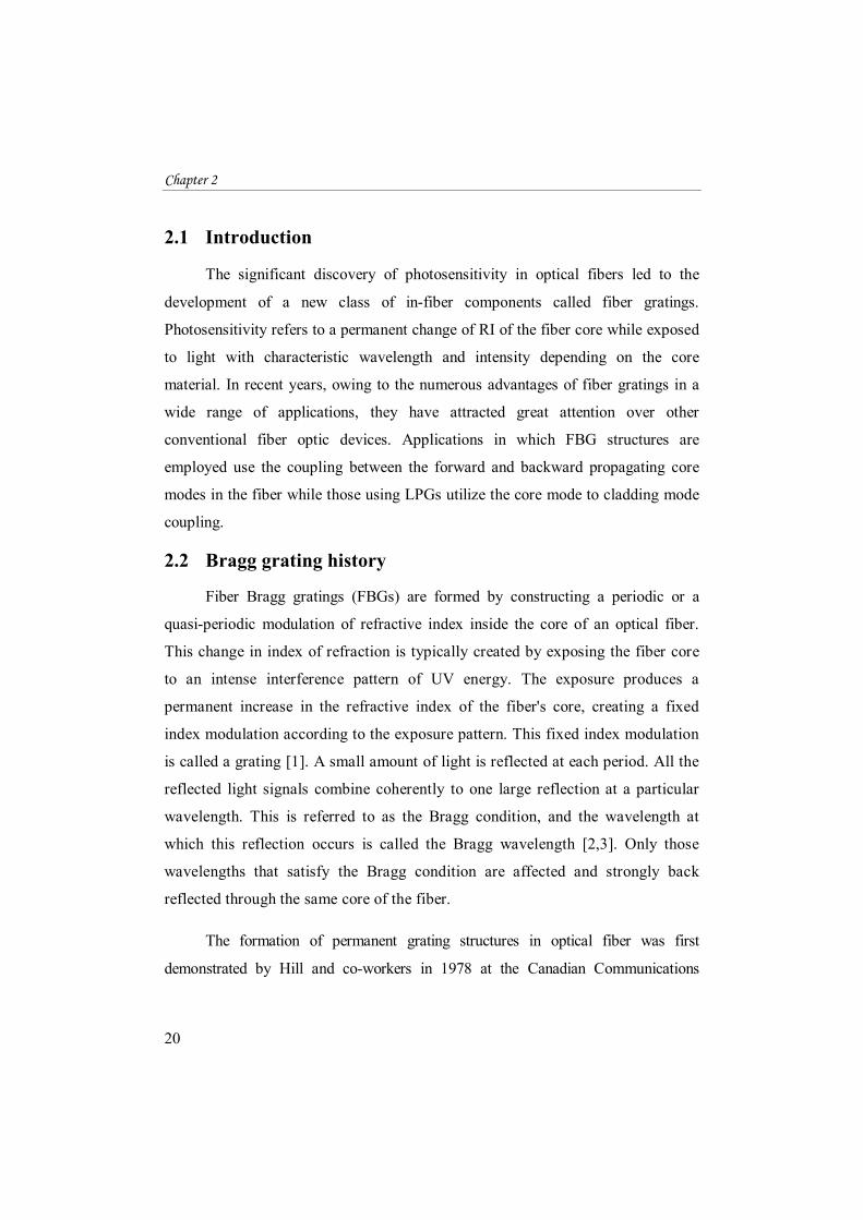
A fiber Bragg grating consists of a periodic modulation of the refractive
index in the core of a single-mode optical fiber. Schematic and operation of basic
FBG are illustrated in Fig. 2.1. When light from a broadband source is launched
from one side of the fiber, only a particular wavelength which satisfies Bragg
condition will be reflected while the remainder is transmitted without any loss.
Periodic RI variations reflect the incoming wave front and constructively form a

Fiber Gratings: Basic Theory and Sensing Principle
23
back reflected power peaked at a centre wavelength defined by the grating
characteristics. The wavelength for which the incident light is reflected with
maximum efficiency is called the Bragg wavelength [1,3,10,11]. In optical fiber
gratings, the phase matching condition is given by [1]:
− = =Λ
........................................................... (2.1) where β1 and β2 are the propagation constants of the modes being coupled and Λ is
the grating period. In the case of FBGs, the forward propagating core mode (LP01)
couples to the reverse propagating core mode. i.e. Propagation constants remain the
same but with a negative sign.
= − = ................................................................ (2.2)
Therefore the phase matching condition becomes − (− ) =Λ
................................................................ (2.3) 2 = =
Λ ................................................................... (2.4)
Since Δβ is large in this case, the grating periodicity will be small, typically less than 1μm. But = ....................................................................... (2.5)
where is the effective refractive index of fiber core. Now the equation (2.4)
becomes
2 =Λ
............................................................ (2.6) Thus the Bragg wavelength can be written as: = 2. .Λ ................................................................. (2.7)
Chapter 2
24
where neff is effective refractive index of the fiber core and Λ is the grating period.
So any change in the effective refractive index or the grating period will cause a
shift in the reflected Bragg wavelength. The wavelengths, other than λB will
experience weak reflection at each of the grating planes because of the phase
mismatch over the length of the grating. The grating spacing can be changed,
during manufacturing, to create Bragg gratings of different center wavelengths.
Comprehensive explanation of FBG basic principles can be found in several
references [4,11]. In some papers, the coupled-mode theory [12] is used as a
technique for the detailed theoretical analysis of FBGs, because it is simple and
accurate in simulating the optical behavior and in modeling the optical property of
most the fiber gratings.
Figure 2.1: Schematic representation of a Bragg grating inscribed into the core of
an optical fiber. The period of the index of refraction variation is represented by Λ.
2.3.1 The Bragg condition
The Bragg grating resonance condition is the requirement to satisfy both
energy and momentum conservation, in which the energy conservation (hwi=hwf)
requires that the frequency of the reflected radiation should be the same as that of
the incident radiation. The momentum conservation requires that the sum of
Fiber Gratings: Basic Theory and Sensing Principle
25
incident wave vector ( i) and the grating wave vector ( ) should be equal to the
wave vector of the scattered radiation ( f). This can be expressed as
k + K = k .................................................................. (2.8)
where the grating wave vector K, has a direction normal to the grating plane with a
magnitude 2π/Λ, with Λ being the grating spacing [3,13]. The diffracted wave
vector is equal in magnitude and opposite in direction with regard to the incident
wave vector and hence the momentum conservation condition can be represented
as [3,10]
2 πλB =
Λ ................................................................. (2.9)
This simplifies to the first order Bragg condition
λB = 2 Λ .............................................................. (2.10)
where λB is the Bragg wavelength and is effective refractive index of the
fiber core. If the Bragg condition is not satisfied, the reflected light from each
subsequent plane in the grating becomes out of phase progressively and gradually
cancel out. Also, light that is not coincident with the Bragg wavelength will simply
get transmitted and experience very little reflection.
2.3.2 Induced refractive index change
The simplest uniform fiber Bragg grating structure in optical fiber is an
axial (x) and periodic change of the refractive index of the core with a
refractive index profile given by[3,13]:
( ) = + ....................................... (2.11)
Chapter 2
26
where Δn is the amplitude of the induced refractive index perturbation, is the
averag index of the fiber core, x is the distance along the fiber’s longitudinal axis
and Λ is the grating period.The typical value of Δn varies in the range 10-5 to10-2.
2.3.3 Bragg grating reflectivity
The reflectivity of a grating with constant modulation amplitude and period
can be expressed using the coupled mode theory of Lam and Garside as [3,14]
R(l, λ) = Ω ( )∆ ( ) ( ) ................................... (2.12)
where R(l, λ) is a fraction between 0 and 1 of the propagating optical power reflected
by a grating of length l at a given wavelength λ. ∆k = k − πλ is the detuning wave
vector, k = πλ
is the propagation constant and s= Ω − Δk . The coupling
coefficient, Ω, for a sinusoidally varying index modulation along the fiber axis is
given by:
Ω = π∆ η(V)λ
.................................................................... (2.13)
where Δn is the amplitude of the induced refractive index at a given wavelength λ
and η (V) is a function of the normalized frequency V of the fiber that represents
the fraction of the fiber mode power contained in the core, η (V ) ≈1 − 1 . The
normalized frequency V can be expressed as [14]
= ( − ) ............................................... (2.14)
where a is the fiber core radius, nco and ncl are the core and cladding refractive
indices, respectively. The fiber is single mode at wavelengths for which

Fiber Gratings: Basic Theory and Sensing Principle
27
V ≤ 2.405 [6]. At the Bragg grating center wavelength, there is no wave vector
detuning and Δk equals zero. Therefore, the expression for the reflectivity becomes
( , ) = tanh (Ωl) ........................................................ (2.15)
2.3.4 Spectral reflectivity dependence on grating parameters
Bragg grating has the property of reflecting light within a narrow band of
wavelengths and transmitting the entire wavelength outside that band. The
reflectivity increases with the change in the induced refractive index. It can also be
found that the reflectivity increases with the increase in the length of the grating.
A. Grating strength
The reflectivity of the fiber Bragg grating depends on the grating strength
according to Eqn.2.15. It implies that the reflectivity of the Bragg gratings
can be increased by increasing the magnitude of the refractive index change
[3]. A refractive index modulation of 10-3 in silica fibers is normally
achievable.
B. Grating length
The length of a Bragg grating is dependent on the size of the fabrication
system and is normally limited to a few centimeters. An FBG close to 100%
reflection of the Bragg wavelength can be obtained by increasing the length
of the grating [3].
2.3.5 Full-width at half-maximum (FWHM)
The full-width at half-maximum (FWHM) bandwidth of a grating [15,16] is
the difference between two wavelengths on either side of Bragg wavelength where
reflectivity drops to half of its maximum. An increase in length of grating results in

Chapter 2
28
reduced FWHM bandwidth. A general expression for the approximate full width at
half-maximum bandwidth of a grating is given by
∆ = ∆ + .................................. (2.16)
where N is the number of grating planes present in grating structure, ≈ 1 for
strong gratings(for grating with near 100% reflection) and ≈ 0.5 for weaker
gratings [17].
2.4 Sensing principle
Fiber gratings are excellent elements in sensing applications, which is the
main topic of this thesis. The basic principle of operation commonly used in an
FBG based sensor system is to monitor the shift in Bragg wavelength, λB with the
changes in the measurand. The Bragg wavelength of an optical fiber grating is a
function of the grating period (Λ) and the effective refractive index (neff) of the
fiber core and is represented by equation (2.7).
λB = 2 Λ
Thus any change in refractive index or the grating period due to external
measurands will change the Bragg wavelength of the device and can be detected in
either the reflected or transmitted spectrum of FBGs. Strain (ε) and temperature (T)
are the two basic parameters that can directly tune the center wavelength of
FBG [1,3]. i.e. the Bragg wavelength is a function of both the strain and
temperature, λB = λB (ε,T) and they are considered as independent variables
[18,19]. Since the measurand field induces a differential change in the wavelength,
the differential of λB is taken. It can be represented as
Fiber Gratings: Basic Theory and Sensing Principle
29
λB = λB + λB
= (2 Λ) + (2 Λ) ............................. (2.17)
= 2 Λ + 2 Λ + 2 Λ + 2
Λ Dividing the equation by λB = 2 neff Λ becomes,
λB λB =
ΛΛ + +
Λ Λ + .............. (2.18)
This equation shows how the Bragg wavelength is shifted by the strain and
temperature.
The first term in Eq. 2.18 represents the strain effect and the second term
represents the temperature effect on optical fiber grating.
2.4.1 Strain sensitivity of Bragg gratings
The basic operation of FBG strain sensor is based on the measurement of the
peak wavelength shift induced by the applied strain [19]. FBGs can provide
extremely sensitive strain measurements for various materials and structures. Strain
sensing is an important part in a health monitoring system for civil, mechanical,
and aerospace applications. The idea of using FBGs for strain measurement was
first introduced by Bertholds et al. in 1988 [20], where the strain-optic coefficient
of optical fibers has been determined.
The strain induced shift of the fiber Bragg grating results from two effects
(former part of Eq.2.18); the physical elongation of the optical fiber corresponding
to a change in grating spacing and the change in the effective refractive index due
to photo elastic (strain-optic) effects [21,22,23]. The Bragg wavelength shift due to

Chapter 2
30
strain optic effect alone can be expressed in terms of the photoelastic coefficient as
[17, 20]
∆λB = 1 − р λB ε ....................................................... (2.19)
where the term ε is axial strain experienced by the fiber in micro-strain (με), ∆λB is
the shift in wavelength (nm) and р is the photoelastic coefficient (effective strain-
optic constant) of the fiber given by
р = р − ν р + р ................................. (2.20)
where р and р are the components of strain-optic tensor, and ν is Poisson’s ratio.
Figure 2.2 shows the shifts of the wavelength and the grating pitch length
before and after the strain is added on both ends of the fiber. Strain measurements
based on FBG is a rapidly developing technology which is driven by its
performance accuracy and versatility and is being used for structural monitoring
and smart structure applications [24-30].
Figure 2.2: Wavelength shift and pitch length shift when strain is added on the
FBG.
Fiber Gratings: Basic Theory and Sensing Principle
31
2.4.2 Temperature sensitivity of Bragg gratings
The temperature response of the Bragg wavelength is due to two factors
(latter part of Eq.2.18), the thermal expansion of the fiber resulting in a change in
the grating spacing and the change in the effective refractive index of the fiber due
to the thermo-optic effect. Thus the Bragg wavelength shift due to temperature
change can be expressed as
∆λB = (α + ξ) λB ΔT ....................................................... (2.21)
where α =Λ
Λ is the coefficient of thermal expansion, ξ =
represents the thermo-optic coefficient of the fiber and ΔT is the change in
temperature. Both parameters α and ξ are functions of temperature and have been
observed to be non-linear at high temperatures [22,24]. Most materials expand
when the temperature increases. If the fiber expands with increase in temperature
then the grating spacing increases and the Bragg wavelength will shift towards
positive side (red-shift). For silica fibers, the thermo-optic effect is the dominant
factor accounting for approximately 95% of the observed shift in the Bragg
wavelength. The thermal expansion accounts for only 5% of the total effect.
Various authors have reported the use of FBGs for temperature sensing
applications [31-34].
2.4.3 Strain and temperature sensing
As discussed above, FBGs respond to changes in both strain and
temperature. The strain directly affects the FBG as it expands or contracts the
grating period and thus the refractive index is modified whereas, the temperature
sensitivity of an FBG mainly occurs because of the change in induced refractive
index [3]. Therefore if a FBG sensor is subjected simultaneously to both strain and
temperature changes, the combined Bragg wavelength shift can be expressed as
Chapter 2
32
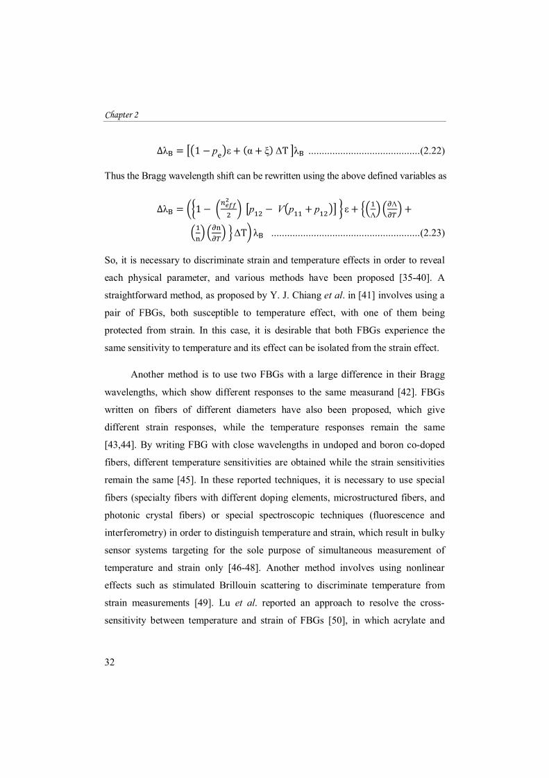
∆λB = 1 − р ε + (α + ξ) ΔT λB .......................................... (2.22)
Thus the Bragg wavelength shift can be rewritten using the above defined variables as
∆λB = 1 − р − Ѵ р + р ε +Λ
Λ + ΔT λB ........................................................ (2.23)
So, it is necessary to discriminate strain and temperature effects in order to reveal
each physical parameter, and various methods have been proposed [35-40]. A
straightforward method, as proposed by Y. J. Chiang et al. in [41] involves using a
pair of FBGs, both susceptible to temperature effect, with one of them being
protected from strain. In this case, it is desirable that both FBGs experience the
same sensitivity to temperature and its effect can be isolated from the strain effect.
Another method is to use two FBGs with a large difference in their Bragg
wavelengths, which show different responses to the same measurand [42]. FBGs
written on fibers of different diameters have also been proposed, which give
different strain responses, while the temperature responses remain the same
[43,44]. By writing FBG with close wavelengths in undoped and boron co-doped
fibers, different temperature sensitivities are obtained while the strain sensitivities
remain the same [45]. In these reported techniques, it is necessary to use special
fibers (specialty fibers with different doping elements, microstructured fibers, and
photonic crystal fibers) or special spectroscopic techniques (fluorescence and
interferometry) in order to distinguish temperature and strain, which result in bulky
sensor systems targeting for the sole purpose of simultaneous measurement of
temperature and strain only [46-48]. Another method involves using nonlinear
effects such as stimulated Brillouin scattering to discriminate temperature from
strain measurements [49]. Lu et al. reported an approach to resolve the cross-
sensitivity between temperature and strain of FBGs [50], in which acrylate and
Fiber Gratings: Basic Theory and Sensing Principle
33
polyimide polymers were used as the coating materials for different FBGs to
achieve simultaneous measurement of axial strain and temperature.
2.4.4 Refractive index sensitivity
In standard single mode optical fibers, the fundamental mode is strongly
shielded by the cladding layer avoiding any influence of the surrounding medium
refractive index on the guiding properties. So the effective refractive index is not
influenced by the external one, thus leading to no sensitivity to surrounding
medium refractive index. However, if cladding diameter is reduced partially or
totally along the grating region, the effective refractive index is significantly
affected by the surrounding medium [51-53]. As a direct consequence, strong
changes in the spectral response of the FBGs occur in etched optical fiber. This
effect can be useful in chemical as well as in bio sensing applications [54-58]. The
first demonstration of an FBG as a refractometer was done in 1997 by Asseh et al.
[59], and it was based on the application of chemical etching to the fiber region
where the grating was located. Usage of chemically etched fiber Bragg grating as
refractive index sensor is discussed in detail in chapter 5 of this thesis.
2.5 Photosensitivity in optical fibers
The photosensitivity in optical fibers refers to a permanent change in the
refractive index of the core of the optical fiber when exposed to light radiation with
characteristic wavelength and intensity that depends on the fiber material [1,60].
The significant discovery of photosensitivity in optical fibers led to the
development of a new class of in-fiber components called fiber gratings. The
existence of high photosensitivity within a fiber core is crucial to the fabrication of
high quality Bragg gratings. Photosensitivity in fiber was discovered by Hill et al.
[4] in 1978 while they were studying the nonlinear effects in a specially designed
high silica optical fiber using 488nm radiation and since then, several published
Chapter 2
34
studies have explained the photosensitivity mechanisms. The refractive index
change reported by Hill was due to two photon absorption and was determined by
Lam and Garside [13]. They concluded that using a UV light source would be more
effective in the fabrication of fiber gratings. Since then, photosensitivity in optical
fibers remained dormant for several years, mainly due to limitations of the writing
technique. However, a renewed interest has risen with the demonstration of the side
writing technique by Meltz et al. [6] almost ten years later.
Numerous studies have been conducted to understand the mechanism of
photosensitivity of optical fiber. Studies have also been conducted to discover for
fibers of higher photosensitivity and more efficient FBG fabrication techniques. In
the early research, it was believed that the photosensitivity exists only in germanium
doped fibers [61], but later studies reported the photosensitivity in a wide range of
different fibers, that contain dopants other than germanium and which contained no
germanium at all [62,63]. However, germanium doped fibers are still the most
interesting photosensitive fibers for grating fabrication due to their extensive
applications in optical sensor and telecommunication area. Photosensitivity is also
detected when the fiber is exposed to different wavelengths of radiations (157nm,
193nm, 244nm, 248nm, 255nm, 266 nm, 325nm, 351nm etc.) [64-66].
2.5.1 Photosensitivity models
Regardless of the worldwide interest into the subject, there is still no single
model to explain the Photosensitivity in all cases, but it has been realized that the
photosensitivity depends on a number of factors, including the core material, the
wavelength and intensity of the radiating light. Several models have been proposed
for these photoinduced refractive index changes, such as colour-centre model [67],
compaction model [68], stress relief model [69], dipole model [70], electron
charge migration model [71], ionic migration model [72] and Soret effect [73].
Fiber Gratings: Basic Theory and Sensing Principle
35
These models have been reviewed extensively in many papers [1,3,74]. To date,
the colour centre model is the most widely accepted model for the formation
mechanism of fiber gratings. According to the colour centre model, photosensitivity
is related to defects present in glass.
The colour centre model is based on the breaking of the germanium-oxygen
vacancy defect bonds in germanium-doped silica on absorption of UV radiation
around the 244 nm wavelength band. On absorption of a photon, the GeO defect
bond breaks forming a colour centre characterized by the presence of a Si+ hole and
a released electron that is free to move within the glass matrix and can be retrapped
at the original site or at some other defect site. The newly trapped electron causes a
reconfiguration of the shape of the molecule which changes the absorption
properties of doped silica in the UV region of the spectrum, leading to an increase
in the refractive index given by the Kramers-Kronig relationship [74]. The colour
centre model for photosensitivity was supported by many experiments [75-77]. The
compaction model or densification model [78] suggests that the UV radiation
breaks bonds in the glass network causing the glass structure to compress and its
density to increase, producing the refractive index change. The stress-relaxation
model is based on the assumption that breaking of chemical bonds on exposure to
UV radiation results in the relief of compressive internal stress which is frozen
within the core of the fiber during the fiber drawing process. Thus the change in
refractive index is characterized by the photo elastic process of stress relief during
fabrication [69]. The electron charge migration model is based on the appearance
of a periodic electric field by photoexcitation of fiber defects.
2.5.2 Photosensitivity enhancement techniques
Since the discovery of photosensitivity and the first demonstration of grating
formation in germonosilicate fiber by Hill in 1978, considerable efforts have been
made to understand and increase the photosensitivity in optical fibers. The
Chapter 2
36
developed photosensitization techniques, including hydrogen loading, flame
brushing and co-doping in fiber core are able to increase the photoinduced index
modulations in the fiber core up to the order of 10-3 - 10-2. This section discusses
different techniques available to enhance the photosensitivity in optical fibers
2.5.2.1 Hydrogen Loading or Hydrogenation Technique
Hydrogen loading of optical fibers is the most commonly used technique for
achieving high UV photosensitivity in germanosilicate and germanium-free optical
fibers and was first developed by Lemaire et al. in 1993 [79,80]. Hydrogen loading is
carried out by diffusing hydrogen molecules into the fiber core at high pressure and
temperature. This method is beneficial in that it allows any optical fiber to have Bragg
gratings inscribed in them. Under UV laser radiation, the hydrogen that is diffused into
the fiber reacts with the Ge-O-Si bonds in the glass, forming additional OH species.
This raises the level of oxygen-deficiency in the glass matrix and hence increases the
amount of absorption at 240nm. The time required for hydrogenation of fiber to
achieve a certain photosensitivity level varies with the pressure and temperature. It
normally takes a week of hydrogen soaking at room temperature in order to obtain the
desired photosensitivity in optical fiber. The required time can be decreased to a few
days by raising the temperature or the pressure during the hydrogen loading process.
But it should be noticed that high pressure hydrogen is dangerous and demands special
precautions.
There are several advantages with hydrogenation technique. It offers a very
simple and effective way to substantially increase a fiber’s photosensitivity.
Fabrication of FBG is possible in any germanosilicate fibers, and even in
germanium-free fiber when shorter wavelength UV light is used (typically 193 nm).
Additionally, permanent refractive index changes occur only in regions that are
UV irradiated. The fiber loses its photosensitivity when hydrogen molecules
diffuse out. Therefore, by thermally diffusing out the hydrogen molecules after
Fiber Gratings: Basic Theory and Sensing Principle
37
the index change, the grating will have high photo-stability even in the UV
wavelength region. The hydrogen loading technique also removes the necessity
of using UV wavelengths, coinciding with defect absorption bands for accessing
photosensitivity [81].
The major disadvantages of this process are that it uses high pressure
hydrogen, which in itself is very dangerous and requires special precautions.
Another drawback of this method is the strong absorption near the 1550 nm
telecommunication window which arises due to increase O-H bond formation
during hydrogenization. Thermal annealing process diffuses out the excess hydrogen
present in the fiber. But this process can shift the resonance peak up to a few
nanometers, thus causing difficulties in reproducing the same Bragg resonance
wavelength repeatedly. The Bragg wavelength caused by the out diffusion of
hydrogen molecules can also affect the stability of gratings used in elevated
temperature sensing applications.
2.5.2.2 The flame brushing
This technique is based on brushing the fiber repeatedly with a flame
fuelled with hydrogen and a small amount of oxygen at a temperature of
approximately 1700°C to achieve photosensitization [82]. At this temperature,
hydrogen diffuses into fiber core very quickly and it takes only approximately
20 minutes to photosensitize a fiber completely. The principle of flame brushing
technique is the same as hydrogen loading technique. Hydrogen molecules are
used to create defects that strongly absorb at UV wavelength, and increase
photosensitivity. Highly localized photosensitivity can be obtained in fiber
because of the fact that the flame can be made very small in size. The effect only
targets the core of the fiber while the cladding properties remain unaffected. The
flame brushing technique has been used to increase the photosensitivity of

Chapter 2
38
standard optical fiber by a factor greater than 10, achieving refractive index
changes of greater than 10-3. The major advantage of the flame brushing
technique over hydrogen loading is that the increased photosensitivity is
permanent when the fiber has been flame brushed, whereas hydrogen loaded fiber
loses photosensitivity as the hydrogen diffuses out of the fiber. The biggest
disadvantage of this technique is that the exposure to high temperature flame
greatly reduces the mechanical property and durability of the fiber which
increases the likelihood of the fiber breaking.
2.5.2.3 Co- doping Technique
The other schemes for increasing the photosensitivity in optical fibers
include, increasing the concentration of germanium in germanosilicate fiber or
codoping of the fiber preforms with co-dopants such as boron [83], europium
[84], cerium [85], erbium [86], phosphorous [87], antimony [88] and tin [89]
which exhibit different degrees of sensitivity in silica host optical fiber.
Germanium doping increases the intrinsic photosensitivity but also enhances the
refractive index of the silica. For communication fibers, the refractive indices of
the core and cladding and numerical aperture are standardized.
Studies have shown that fiber co-doped with boron to be much more
photosensitive than fiber with higher germanium concentration and without
boron co-doping. Addition of boron oxide to silica results in a compound glass
that has a lower refractive index than silica. So boron co-doping reduces the RI of
the core and makes it softer than before. Fiber indices may be matched with high
concentrations of germanium as long as the boron concentration is sufficient.
The absorption measurements suggest that in contrast to hydrogen loading and
flame-brushing techniques, boron co-doping does not enhance the fiber
photosensitivity through the creation of oxygen-germanium deficiency centers.
Fiber Gratings: Basic Theory and Sensing Principle
39
Instead, it is believed that boron co-doping increases the photosensitivity of the
fiber by allowing photo induced stress relaxation to occur, which seems likely to
be initiated by the breakage of bonds by UV light. Tin co-doped fibers exhibit
similar photosensitivity as those doped with boron. But the Sn co-doped fibers
also benefit from some advantages over boron doped fibers including the grating
survival at high temperature and their induced refractive index changes are more
stable with time [90].
2.6 FBG Fabrication Technology
Since the discovery of photosensitivity in optical fibers, there has been a
growing interest for fabrication of Bragg gratings within the core of an optical
fiber. Direct optical inscription of high quality gratings into the cores of optical
fibers has been actively pursued by many research laboratories and various
techniques have been reported. Different FBG fabrication techniques can be
classified as internal inscription and external inscription techniques [3,4].
Adopted primarily during the earlier years, internally writing technique uses
relatively simple experimental setup in which the standing wave inside the
optical fiber photo imprints a Bragg grating with the same pattern as the standing
wave. In recent years, the internal inscription technique has been superseded by
the external inscription technique due to the inefficiency of the writing process.
In this, gratings are side written into the core of a photosensitive fiber by
exposure to a UV light source and generally have greater reflectance due to the
large index modulation. Currently, there are three basic external writing
techniques for FBGs fabrication in photosensitive optical fibers with the
necessary accuracy namely: Interferometric technique [6,85,91,92], Phase Mask
Technique[93-108] and Point-by-Point Inscription method [109-110]. These
techniques differ in the principle of writing and consequently, in the equipment
used in the grating writing process.
Chapter 2
40
The interferometric fabrication technique, the first external writing
technique to inscribe Bragg gratings in photosensitive fibers, was demonstrated
by Meltz et al. in 1989 [6], in which a single laser beam is split into two
components, which are subsequently recombined at the fiber to produce an
interference pattern. Bragg gratings can be written interferometrically by
amplitude-splitting [6,90] or by wavefront-splitting [14,91,92].
The first demonstration of the point-by-point technique for writing FBG was
reported by Malo et al. in 1993 [109]. This technique uses a UV pulse laser or
femtosecond laser [110] to inscribe individual grating planes one step at a time
along the core of the fibre. A single pulse of light passes through a slit and then is
focused onto the core of the optical fiber to produce an index change at one point.
After the refractive index at the irradiation point is changed, the fibre is translated
by a distance Λ, which corresponds to the grating period, from the original place by
a precision translation stage. The movement of the translation stage is computer
controlled. This procedure is repeated until the desired grating length is obtained.
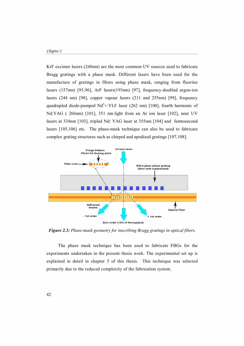
The phase mask method is the most widely used and effective method for
inscribing FBGs in photosensitive fibers [90]. This technique makes use of
phase mask as a key component of the interferometer to generate the
interference pattern. A Phase mask is a corrugated grating etched in a silica
substrate produced either by holographic or by electron-beam lithography
method [93,94]. The phase mask is normally placed in contact or near contact
with the fiber. The laser beam passes through the mask and is spatially
diffracted to form an interference pattern. This interference pattern photo
imprints a refractive index modulation in the core of the photosensitive optical
fiber as shown in Fig.2.3.

Fiber Gratings: Basic Theory and Sensing Principle
41
With a normally incident UV radiation, the phase mask diffracts the incident
beam into several orders, m=0, ±1, ±2 ... and the diffraction angle of the positive
and negative orders are equal. The superpositions of the different plus and minus
diffraction orders form an inference pattern, which can be used to inscribe Bragg
gratings in optical fibers. Normally, the near field interference fringe pattern,
generated by ±1 order diffraction is employed for grating fabrication. Phase masks
for FBG fabrication are usually designed such that the zero order diffracted beam is
suppressed to less than few percent (typically less than 3%) of the transmitted light
when the light is incident on the mask. The diffracted plus and minus first (±1)
orders are maximized, each containing, typically more than 35% of the transmitted
power [14].
Important features in a phase mask are the period of the etched grooves and
the etch depth. The period of the grating (Λg) written in the core of the fiber is one
half of the phase mask period (Λpm) and does not depend on the wavelength of the
writing beam or its incident angle on the phase mask.
Λ = Λ ................................................................. (2.24)
To achieve the minimization of the zero order diffraction, the etching depth d of
the relief grating in phase mask is controlled to be:
d = ....................................................................... (2.25)
where λuv is the wavelength of UV irradiation. From this equation, it can be
concluded that in FBG inscription, for each UV laser source working at a
different wavelength, a different phase mask needs to be used. This is the major
disadvantage of the phase mask based fabrication method. The wavelength of
the UV light source is selected based on the absorbance spectra of the doped
optical fiber core – thereby maximizing the source’s efficiency in FBG writing.
Chapter 2
42
KrF excimer lasers (248nm) are the most common UV sources used to fabricate
Bragg gratings with a phase mask. Different lasers have been used for the
manufacture of gratings in fibers using phase mask, ranging from fluorine
lasers (157nm) [95,96], ArF lasers(193nm) [97], frequency-doubled argon-ion
lasers (244 nm) [98], copper vapour lasers (211 and 255nm) [99], frequency
quadrupled diode-pumped Nd3+:YLF laser (262 nm) [100], fourth harmonic of
Nd:YAG ( 266nm) [101], 351 nm light from an Ar ion laser [102], near UV
lasers at 334nm [103], tripled Nd: YAG laser at 355nm [104] and femtosecond
lasers [105,106] etc. The phase-mask technique can also be used to fabricate
complex grating structures such as chirped and apodized gratings [107,108].
Figure 2.3: Phase-mask geometry for inscribing Bragg gratings in optical fibers.
The phase mask technique has been used to fabricate FBGs for the
experiments undertaken in the present thesis work. The experimental set up is
explained in detail in chapter 5 of this thesis. This technique was selected
primarily due to the reduced complexity of the fabrication system.
Fiber Gratings: Basic Theory and Sensing Principle
43
2.7 Long Period Gratings (LPGs)
Significant research efforts have been devoted to the study of Long Period
Gratings (LPGs) since it was first reported in 1996 [111,112]. An LPG can be
formed by the introduction of a periodic modulation to the optical properties of the
fiber with a pitch of the order of 100μm [113]. The periodic modulation can be
realized by a permanent modification of the refractive index of the fiber core or by
a physical deformation of the fiber. The transmission spectrum of a typical LPG
consists of a number of attenuation bands at specific wavelengths (resonance
wavelengths), each of which corresponds to the coupling between the guided core
mode and a particular cladding mode [114]. The study of the LPG’s attenuation
bands has yielded many potential applications in fiber-optic communication and
sensing fields. The centre wavelengths of the attenuation bands are dependent on
the composition of the fiber, and are influenced by environmental factors such as
temperature [114,115], strain [116-118], refractive index [119-121] of the material
surrounding the fiber and bend radius [117,122]. Thus it may be used for multi-
parameter sensing applications. The principle of operation mechanism of long-period
grating sensors is based on the modulation of the effective indices of the core and
cladding modes and/or the grating periodicity by the external perturbation [123]. In
comparison with fiber Bragg gratings (FBGs), LPGs offer a number of advantages,
including easy fabrication, low insertion loss, and better wavelength tunability.
This section introduces the sensing capabilities of long-period gratings based
on the above mentioned principle. Firstly, the LPG theory and the basic principle
of operation of LPG based sensors are discussed and then the mechanism behind
the spectral shifts in the resonance band is explored. It is shown that for a given
LPG, the wavelength shifts are strong functions of the grating period and the order
of the corresponding cladding mode. The temperature and strain sensitivity of the
Chapter 2
44
LPG is discussed and furthermore long-period gratings are shown to be highly
sensitive to index changes of the medium surrounding the bare cladding.
2.7.1 Mode Coupling in LPG
In optical fiber gratings, the phase matching condition is given by [111]: − = =
Λ ......................................................... (2.26)
where β1 and β2 are the propagation constants of the modes being coupled and Λ is
the grating period [124,125].
In the case of LPGs, the forward propagating core mode couples to the
co-propagating cladding modes of order m. Then
− , = =Λ
................................................. (2.27) where is the propagation constant of core and , is that of mth order
cladding mode. In this case Δβ is small and hence the grating periodicity will be
very large compared to FBG grating period. Substituting the values as done in the
case of FBG, we will get the resonance wavelength condition as [111,112]:
= n − n , Λ .................................................... (2.28)
where λ is the resonance wavelength corresponding to coupling to the mth
cladding mode, Λ is the grating period, n is the effective index of the
fundamental core mode (LP01), n , is the effective index of the mth order
cladding mode (LP0m). Comprehensive explanation and analysis of mode coupling
in fiber gratings and theory of LPGs can be found in several books [72,126,127],
and in published literature [114,123,124,128,129].
Fiber Gratings: Basic Theory and Sensing Principle
45
2.7.2 Phase Matching Curve (PMC)
The neff for each resonant wavelength can be calculated after identifying the
modes in simulation software (eg: OptiGrating). Using this neff, corresponding to
each cladding modes for various wavelengths, grating period versus wavelength
can be plotted using the equation (2.28). Therefore
Λ = , ........................................................... (2.29)
Thus for various modes, period versus resonant wavelength can be plotted.
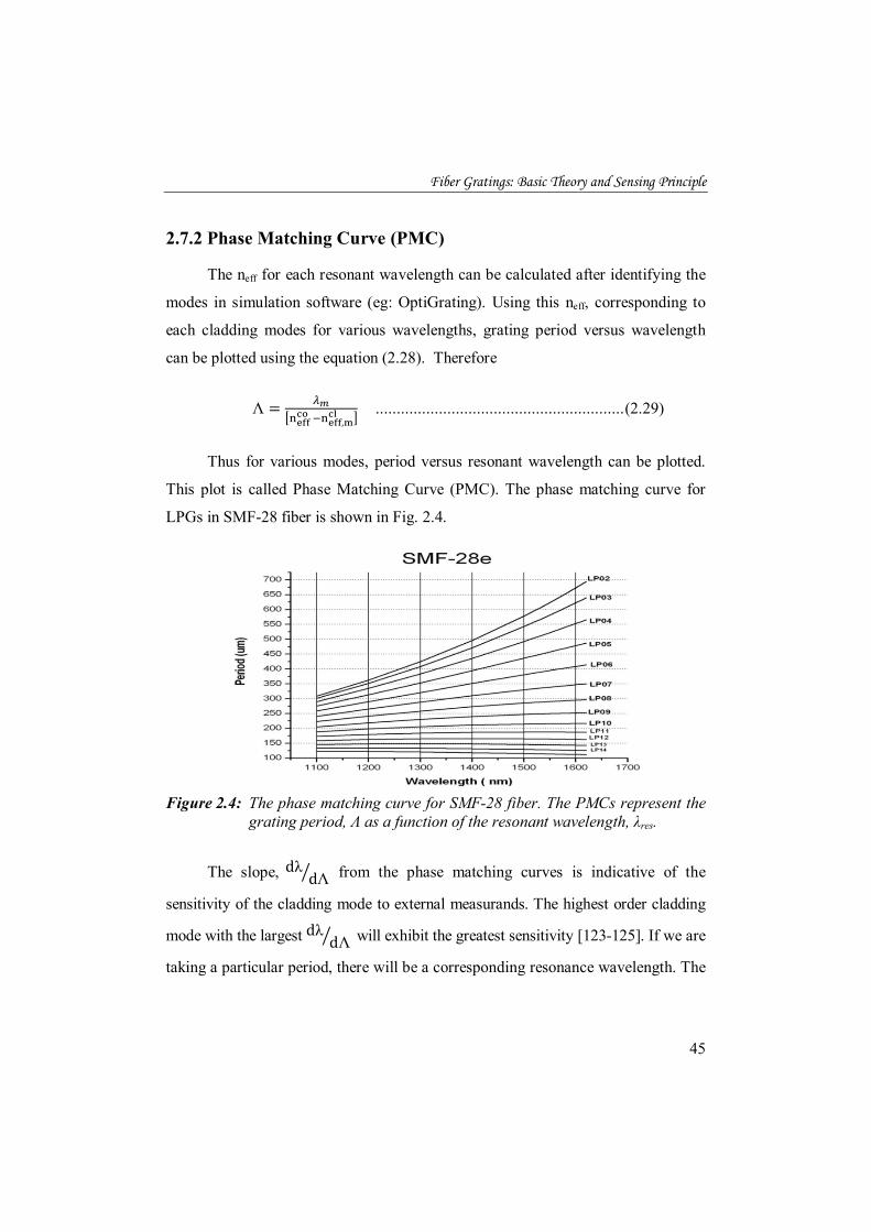
This plot is called Phase Matching Curve (PMC). The phase matching curve for
LPGs in SMF-28 fiber is shown in Fig. 2.4.
Figure 2.4: The phase matching curve for SMF-28 fiber. The PMCs represent the
grating period, Λ as a function of the resonant wavelength, λres.
The slope, dλ dΛ from the phase matching curves is indicative of the
sensitivity of the cladding mode to external measurands. The highest order cladding
mode with the largest dλ dΛ will exhibit the greatest sensitivity [123-125]. If we are
taking a particular period, there will be a corresponding resonance wavelength. The
Chapter 2
46
intersection of the curve with period of grating gives the corresponding wavelength
of attenuation.
From Fig. 2.4 several important observations can be made: (1) For a specific
grating period, the LPG can couple the energy of the fundamental mode into
multiple other modes simultaneously at different resonant wavelengths; (2) For a
certain resonant wavelength, a particular grating period can be chosen to allow the
LPG to couple the fundamental mode into a certain fiber mode; (3) The higher the
coupled fiber mode order, the shorter the grating period required to achieve mode
coupling; (4) The slope, dΛ/dλres progressively decreases from the lower order
modes to the higher order modes. Consequently, dλres/dΛ progressively increases
from lower order mode to higher order mode. This shows that the change in λres as
a result of the change in Λ gets larger as the order of the coupled fiber mode
increases for the same LPG. The change in Λ can result from the change in strain
on the grating or the change in ambient temperature. Consequently, the sensitivity
of the LPG to strain or temperature increases with increase in fiber mode order for
the same LPG.
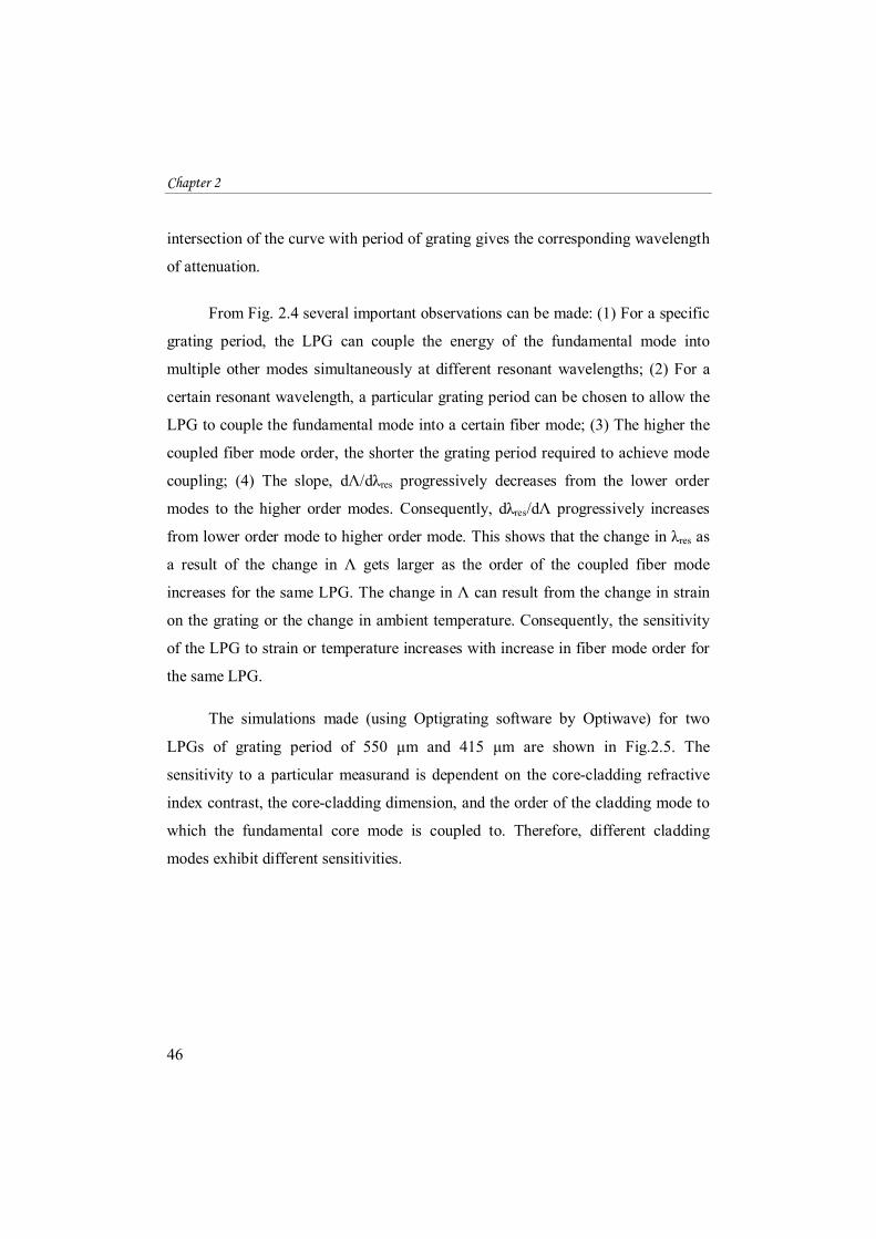
The simulations made (using Optigrating software by Optiwave) for two
LPGs of grating period of 550 μm and 415 μm are shown in Fig.2.5. The
sensitivity to a particular measurand is dependent on the core-cladding refractive
index contrast, the core-cladding dimension, and the order of the cladding mode to
which the fundamental core mode is coupled to. Therefore, different cladding
modes exhibit different sensitivities.
Fiber Gratings: Basic Theory and Sensing Principle
47
Figure 2.5: Simulated transmission spectra of LPG-1 with a grating period of
550 μm and LPG-2 with a grating period of 415 μm using Optigrating software by Optiwave.
2.8 Principle of operation of LPG based sensor
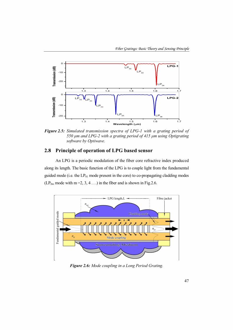
An LPG is a periodic modulation of the fiber core refractive index produced
along its length. The basic function of the LPG is to couple light from the fundamental
guided mode (i.e. the LP01 mode present in the core) to co-propagating cladding modes
(LP0m mode with m =2, 3, 4 . . .) in the fiber and is shown in Fig.2.6.
Figure 2.6: Mode coupling in a Long Period Grating.
Chapter 2
48
As the cladding modes are weakly guided and suffer from high attenuation, the
transmission spectrum of a typical LPG consists of a series of attenuation bands at
discrete wavelengths. The wavelength at which the guided mode couples to the
cladding modes can be obtained through the phase-matching equation [113,130]:
λ = n − n , Λ We can also write λ = (δn ) Λ ....................................................................... (2.30)
where δn is the differential effective index between the guided and
cladding mode (neff co − neff,mcl ) at wavelength λm. For a typical long period grating,
more than one cladding mode can satisfy the phase matching condition at different
wavelengths, and the guided mode will be coupled to all those cladding modes.
The strength of transmission of the attenuation bands [113] can be written as
Tm = 1 − sin2 (kmL) ................................................................ (2.31)
where L is the length of LPG and km is the coupling coefficient for mth cladding
mode. Therefore, the coupled power % depends on L and km. The parameter km
however depends on the specific cladding mode and also the amplitude of
refractive index modulation (Δnco) induced in the fiber core.
The resonance wavelength of LPG is a strong function of external
perturbations like strain [115], temperature [117], bending [111] and SRI [119].
Presence of these external perturbations affects the coupling strength between the
core and cladding modes, which could lead to both amplitude and wavelength shift
of the attenuation bands in the LPG transmission spectrum [131,132]. Measurement
of these spectral parameters in response to environment, surrounding the grating
region is the basis of sensing with LPGs. The shift in the coupling wavelength can
Fiber Gratings: Basic Theory and Sensing Principle
49
be determined using an optical spectrum analyser(OSA) to produce a simple LPG
based sensor. A complete analysis of the sensitivity of LPGs to external ambient is
necessary prior to practical device design. In 2002, Shu et al. [133] have
presented a complete investigation of the shift in the center of the resonance
wavelength of the LPG due to temperature, strain and external refractive index
variations, and can be expressed as
∆ = ∆ + ∆ + ∆n ........................ (2.32)
where dλmdT
, dλmdε
and dλmdnsur
are the temperature, strain and surrounding
refractive index sensitivity of the resonant wavelength, respectively. In the following
sections a detailed expression for such sensitivities will be discussed.
2.8.1 Wavelength dependence of long-period gratings on temperature
The temperature sensitivity of LPGs arises from two major contributions:
1) changes in the differential refractive index of the core and the cladding due to
thermo-optic effects, 2) changes in the LPG’s period with the temperature. The
sensitivity of an LPG to temperature, T, can be explained by taking the temperature
derivation of the phase matching condition to give [114, 133-135]
λT = λ(δ ) T − , ) T + Λ λΛ L LT ............................... (2.33)
where T is the temperature, L is the length of LPG, and δneff is the effective
differential refractive index between the core mode and the cladding mode
(ncoeff- ncl,meff ). The wavelength shift is mainly influenced by the grating period [4],
the order of the cladding mode to which coupling takes place [114] and by the
composition of the optical fiber [133].
Chapter 2
50
The right hand side of the equation (2.33) contains two terms that may be
separated as two contributing terms to the wavelength response. The first term
represents a thermo-optic effect and is described as the material contribution. It is
related to the change in the differential refractive index of the core and cladding
arising from the thermo-optic effect. This contribution is dependent upon the
composition of the fiber, i.e. different fiber types having different thermo-optic
coefficients. It is also dependent upon the order of the cladding mode. Different
temperature dependent spectral response can be observed when coupling occurs with
lower-order cladding modes as opposed to modes of higher order [114,115,136].
For coupling to lower order cladding modes, which are accessed using a large
grating period (in excess of 100 μm), the material effect dominates. On the other
hand, coupling to higher-order cladding modes takes place in LPGs with relatively
short periods (less than 100μm). When these shorter period LPGs are exposed to
temperature fluctuations the material contribution can become negligible. The
second term on the right hand side of equation (2.33) is the waveguide
contribution. This contribution arises from changes in the grating periodicity and
can be negative or positive depending on the order of cladding mode [123].
Shu et al. [133,135] also derived an equation for the temperature sensitivity
of the resonance wavelengths of LPGs as
( )Tmm
dTd
Γ+= αγλλ
................................................................ (2.34)
where T is the temperature, α is the thermal expansion coefficient of silica, γ is the
contribution of the waveguide dispersion and Γ is a measurand-specific factor,
which reflects the influence of the measurand on the dispersion of the LPG. The
specific sensitivity factor for temperature, TΓ and γ are given by [137,138]
Fiber Gratings: Basic Theory and Sensing Principle
51
effmcl
effco
m
nndd
,−Λ=
λ
γ
....................................................................... (2.35)
effmcl
effco
effmclcl
effcoco
T nnnn
,
,
−−
=Γξξ
.............................................................. (2.36)
where coξ and clξ are the thermo optic coefficients of the core and the cladding,
respectively. TΓ is determined by the temperature dependence of the refractive
index of the core, which depends on the composition of the fiber( SiO2, GeO2,
B2O3 etc.).
As α has a small value at room temperature, it is negligible compared with
TΓ and the temperature sensitivity is determined by the term γ .TΓ Equation (2.33)
highlights the importance of the relative temperature dependencies of the effective
refractive indices and therefore the magnitudes of the core and cladding thermo-
optic coefficients (respectively coξ = dnco/dT and clξ = dncl/dT) [139] in determining
LPG wavelength sensitivity to external temperature fluctuations.
The direction of attenuation band shift depends on the relative magnitudes of
the core and cladding thermo-optic coefficients [133,140]. The thermo optic
coefficient of the core depends on the concentration of the dopants in silica. GeO2
has a larger thermo optic coefficient than that of SiO2, whereas B2O3 has a negative
thermo optic coefficient. In the case of standard fiber, the core contains SiO2 and
GeO2 and the cladding contains only SiO2. So the thermo optic coefficient of the
core will be higher than that of the cladding ( effcoconξ > eff
mclcln ,ξ and TΓ >0). As a
result when the temperature increases, these fibers will show a wavelength shift
towards longer wavelengths [135,140]. On the other hand, the boron co-doped
fibers will show a wavelength shift towards shorter wavelengths due to the
Chapter 2
52
negative thermo optic coefficient of the boron dopant ( effcoconξ < eff
mclcln ,ξ and TΓ <0)
[133,140,141]. Thus, it is to be expected that the thermal responses of LPFGs
produced in different fiber types will exhibit different trends. The temperature
sensitivity of the resonance wavelength of LPGs can be increased by coating the
LPGs with polymer materials that have large thermal-optic coefficients [142,143] or
by etching the fiber cladding [144]. Long-period gratings written in microstructure
fiber with large holes in the cladding that were filled with polymer also demonstrated
higher temperature sensitivity [145].
2.8.2 Wavelength dependence of long-period gratings on strain
Strain induces significant variations in the core and cladding refractive
indices of an optical fiber and, unlike the temperature, it also induces significant
changes in the dimensions of an optical fiber. In an LPG the deviation of these
parameters from the unperturbed state gives rise to different coupling of the light
between the propagating modes and, as consequence, corresponding variations in
the transmission spectrum. These variations can be detected and related to the
strain intensity.
The strain response of a long-period fiber grating arises due to the physical
elongation of the fiber, changing the grating pitch and the effective refractive index
of the core and cladding due to the elastooptic effect [145]. Differentiation of the
phase-matching condition with respect to axial strain, ε, provides an equation for
the shift in resonant wavelength with axial strain [114,115,136].
λε
= λ(δ ) ε− , )
ε+ Λ λ
Λ ........................................ (2.37)
Similar to the temperature sensitivity (equation 2.33), there are two terms
which influence the axial strain sensitivity: material and waveguide effects. The
Fiber Gratings: Basic Theory and Sensing Principle
53
first term on the right hand side of the equation is the material contribution and the
second is the waveguide contribution. The material effects are the change in
dimension of the fiber (Poisson’s effect) and the strain-optic effect (refractive
index changes); while the waveguide effect is a function of the slope of the
dispersion term, dλmdΛ
, for a specific cladding mode [115,136]. In short, the shift in
resonant wavelength ( ) of the LPG transmission spectrum is dependent on the
order of the relevant cladding mode(m) that participates in coupling, as well as the
grating period (Λ).
The polarity of the strain coefficient depends on whether the material or
waveguide contribution provides the dominating effect. The two contributions to
the total strain induced wavelength shift can be either positive or negative
depending on the period of the LPG and the order of the cladding mode. For LPGs
with a periodicity > 100μm the material contribution is negative and the waveguide
contribution is positive. When the LPG period is less than 100 μm, both material
and waveguide contributions to the strain sensitivity will be negative. The relative
magnitudes of these contributions will therefore determine if the overall effect
creates an attenuation peak shift to longer or shorter wavelengths. For the case
where the material and waveguide effects cancel each other completely – their
magnitudes are equal but opposite in sign – that particular resonant band becomes
insensitive to axial strain. i.e. By choosing appropriate grating period and fiber
composition, it is possible to get an attenuation band with positive, negative or zero
sensitivity to strain [115,136]. Thus the ability to design an LPG’s response to
strain and temperature opens up the possibility of sensing multi-parameter devices
with the option of isolating either of the measurands. Shu et al. [133,135] derived
an equation for the strain sensitivity of the resonance wavelengths of LPGs as
( )Smmd Γ+= 1
dγλ
ελ
................................................................... (2.38)
Chapter 2
54
where γ is the general sensitivity factor which describe the waveguide dispersion,
and it relates the sensitivity of the LPG to all forms of external perturbation
including strain, temperature and surrounding refractive index [133,138]. The
specific sensitivity factor, SΓ for strain is given by
effmcl
effco
effmclcl
effcoco
S nnnn
,
,
−−
=Γηη
............................................................... (2.39)
where coη and clη are the elastooptic coefficients of the core and cladding
materials, respectively. So, the LPG sensitivity to strain can be expressed as
follows
⎟⎟⎠
⎞⎜⎜⎝
⎛
−−
+= effmcl
effco
effmclcl
effcoco
mm
nnnnd
,
,1d
ηηγλ
ελ
............................................ (2.40)
It can be seen form eq. (2.40) that an LPG is strain-insensitive when the
second term in the parenthesis is equal to -1.
The effect of strain on the wavelength shift of an LPG is different from that
of a fiber Bragg grating. Qualitatively, the FBG and LPG responses are different.
The FBG wavelength is linearly proportional to the grating period multiplied by the
effective index of refraction of the core, the LPG wavelength is proportional to the
grating period multiplied by the difference in index of refraction between the core
and the cladding. Furthermore, the effect of strain on the long-period grating is
more dependent on the fiber type.
2.8.3 LPG Sensitivity to the refractive index of the surrounding medium
Conventional fiber optic refractive index sensors typically use some form of
modification of the cladding to gain access to the evanescent field of the guided
mode. For example, surface plasmon sensors require polishing the fiber cladding
Fiber Gratings: Basic Theory and Sensing Principle
55
and depositing a thin layer of appropriate metal on the polished fiber surface [146].
Limitations of this device include questionable repeatability and mechanical
strength. In an LPG the guided light interacts with the external medium so there is
no need to modify the fiber. In this section we will show that long-period gratings
are highly sensitive refractive index sensors and can be implemented without
sacrificing the integrity of the fiber [111].
The attenuation spectrum of an LPG is highly sensitive to the ambient
refractive index. The refractive index sensitivity of an LPG arises from the
dependence of the phase matching condition on the effective refractive index of the
cladding modes, which are determined by the refractive index of the cladding
material and that of the medium surrounding the cladding. LPG is very useful as a
surrounding medium refractive index sensor when the refractive index of the
external medium changes. The change in ambient index changes the effective
index of the cladding mode and will lead to both amplitude and wavelength shifts
of the resonance dips in the LPG transmission spectrum. The RI sensitivity of
LPGs has been exploited to form RI sensors, biosensors, liquid sensors and
chemical concentration sensors by measuring the small shift in the resonant
wavelength with a change in ambient refractive index [111,120,133,147-149]. The
effect of refractive index of the surrounding medium on the resonance wavelength
is expressed by [114]:
dλmdnsur
= dλmdneff,mcl
dneff,mcl
dnsur ................................................................. (2.41)
where nsur is the refractive index of the surrounding material. For each cladding
mode, the term dneff,mcl
dnsur is distinct and hence an LPG is expected to have a strong
dependence on the order of the coupled cladding mode. Higher order cladding
modes tend to show greater sensitivity to changes in external refractive index

Chapter 2
56
because these modes extend further out into the area exterior to the fiber
[114,120,133]. Shu et al. [133,134] derived an equation for the RI sensitivity of
the resonance wavelengths of LPGs as
surmmd
Γ= ..dnsur
γλλ
.................................................................... (2.42)
The specific sensitivity factor, Гsur for surrounding RI is given by
Г = − λ π , ............................. (2.43)
Where um is the mth root of the zeroth-order Bessel function of the first kind, rcl and
ncl are the radius and refractive index of the fiber cladding, respectively. From
equation (2.43), it is evident that the sensitivity is greater for higher order cladding
modes and it can be enhanced by reducing the cladding radius since the term in
parenthesis is dependent on (r ) [133,150].
The spectral change of LPG sensors can be characterized in terms of
external RI as follows. If the SRI is lower than the refractive index of the
cladding (nsur< ncl), mode guidance can be explained using total internal
reflection. In this case, typically strong resonance peaks are observed and the
attenuation dips shift towards shorter wavelengths (blue shift) when the external
medium refractive index increases up to the fiber cladding refractive index
[133,148]. The closer the refractive index of the external medium to the cladding,
the higher the grating sensitivity and leads to larger wavelength shift. When the
value of the ambient refractive index matches with that of the cladding, the
cladding layer acts as an infinitely extended medium and thus supports no discrete
cladding modes. In this case, a broadband radiation mode coupling occurs with no
distinct attenuation bands [151]. In short, when the external RI becomes equal to
Fiber Gratings: Basic Theory and Sensing Principle
57
the RI of the cladding, rejection bands disappear, and the transmission spectrum
gets flattened. Once the SRI is higher than the refractive index of the cladding
(nsur > nclad), the cladding modes no longer experience total internal reflection and
Fresnel reflection can be used to explain the mode structure [147]. Whatever may
be the value of the external index (> nclad), a part of the energy is reflected at the
interface of the cladding and the external medium. The ratio of the energy reflected
will be determined by the Fresnel coefficients. In this case the resonance peaks
reappear at slightly longer wavelengths (red shift) compared to those measured with
air as the surrounding medium [152,153]. The depth of each attenuation peak
steadily increases with increase in refractive index of the surrounding medium,
owing to larger Fresnel reflection coefficients that yield improved reflection at the
cladding boundary [151,154]. So, chemical concentration changes can also be
measured by studying the amplitude changes in the LPG attenuation dips.
Refractive index sensing is important for biological, chemical and biochemical
applications since a number of substances can be detected through the measurements
of refractive index [118,155-159].
Etching of the cladding diameter is a simple method to improve the
refractive index sensitivity of a long-period gratings following the fabrication
process [144,150]. The sensitivity to the ambient refractive index of an LPG can
also be improved by coating the fiber grating with a thin film of material with
higher refractive index than that of the fiber cladding [131,160-167]. As an
example, an opto-chemical sensor employing LPGs coated with polymeric
sensitive overlays (syndiotactic polystyrene (sPS) in the nanoporous crystalline δ
form) has been proposed [168]. A monolayer of colloidal gold nano-particles has
also been proposed for improving the spectral sensitivity and detection limit of
LPGs [169].

Chapter 2
58
2.9 Fabrication methods for Long Period Gratings
The fabrication of an LPG relies on the introduction of a periodic
modulation of the optical properties of the fiber, which can be in the form of index
modulation along the fiber core [112] or physical deformation along the fiber
[113]. It has been seen that long-period gratings could be fabricated by a number of
methods, which belong to either the UV exposure or non-UV exposure. In the UV
exposure, there is either the point-by-point writing method [182-184] or amplitude
mask technique [112,173,174]. The former method is flexible for fabricating LPGs
with different spectral characteristics but not suitable for mass production, whereas
the amplitude mask techniques could be used for mass production of LPGs.
UV-induced index modulation is typically achieved in germanosilicate optical
fibers using wavelengths between 193 nm and 266 nm [113,175]. The major UV
sources are, radiation from a KrF excimer laser (242-248 nm) [2, 176-178], the
second harmonic radiation of a continuous-wave (CW) Ar ion laser (244 nm)
[179], nanosecond pulses from a ArF excimer laser (193 nm) [180], frequency
quadrupled and tripled Nd:YAG lasers (266nm and 355nm outputs, respectively)
[112,181] etc. UV exposure is the most widely utilized method for the fabrication
of LPGs. Fibers with high UV photosensitivity have been developed by co-doping
the core with boron and germanium [182] and by hydrogen loading [173].
Non-UV methods include CO2 laser irradiation [183,184], electric arc
discharge [185,186], infrared femtosecond laser pulse irradiation [187,188],
mercury-arc lamp [189], ion implantation (bombardment) [190,191] and dopant
diffusion in nitrogen-doped fibers [192]. Advantages of the ion and proton
implantation techniques include the fabrication of LPGs by inducing high
refractive index changes in the core and the possibility to write LPGs in almost any
kind of silica-based fibers. These fabrication techniques have the disadvantage of
increasing the average cladding effective index, leading to losses in the spectrum

Fiber Gratings: Basic Theory and Sensing Principle
59
and requiring specialized equipment to fabricate LPGs. A periodic physical
deformation along the fiber can also be produced by mechanical methods [193-196]
or tapering the fiber [197] or deformation of the core [198] or the cladding [199]. A
simple method to create temporary LPG is to press a periodically grooved plate
onto a fiber, and this is based on the physical deformation to the optical fiber which
can also change the refractive index profile of the fiber core [141,200]. In addition,
dynamic LPGs with controllable transmission characteristics have been implemented
by using coil heaters [201], mechanical loading [202], and liquid-crystal filled
hollow-core fibers [203]. A temporary LPG can also be created using acoustical
modulation of a length of optical fiber (acousto-optic modulation) [204,205].
Long period gratings have been virtually written in all kind of optical fibers,
namely, in standard single mode communications fibers [112], in non-photosensitive
fibers [185,206,207] for EDFAs gain equalisation and sensing, in multimode fibers
for chemical sensing [208], in polarization maintaining fibers [209], in D-fibers for
enhanced RI measurements [210], in specially designed fibers like dispersion
compensating [211], depressed inner cladding [212], dual core [213], twin core
[214] fibers with particular properties for optical communications and sensing.
Recent advances have been focused in the research of LPGs induced in photonic
crystal fibres (PCFs) which consist of a pure-silica core, and a microstructured air-
silica cladding [215,216]. Because the microstructured cladding consists of air holes,
a PCF’s cladding index shows strong wavelength dependence. LPGs have also
been fabricated in planar waveguides for compactness and mass production [217].
A big problem with the UV inscription method is the LPGs fabricated by this
method cannot survive at high temperature. When the temperature goes much beyond
room temperature, the UV written LPG starts to fade and eventually loses the modal
coupling. Among the techniques mentioned above, femtosecond laser, CO2 laser
irradiation and electric discharge are able to fabricate survival LPG at a temperature up

Chapter 2
60
to 1000oC [185]. But femtosecond lasers are too expensive to be used in LPG
fabrication; and CO2 laser irradiation and electric discharge method may significantly
affect the mechanical strength of the optical fibers. A detailed review of the above
fabrication techniques and mechanisms can be found in the review paper [113].
The LPGs used in our experiments were fabricated using a 248 nm KrF
excimer laser source, employing point-by-point writing method [182-184]. A
great advantage of the point-by-point method is that it is a highly flexible
technique, since the grating periodicity and length can be individually adjusted to
meet the desired LPG specifications and corresponding spectral characteristics.
2.10 Annealing of long-period gratings
In the case of fiber gratings fabricated using hydrogen loaded fibers, the
amount of hydrogen present in an optical fiber will be far in surplus of that
required to achieve a given refractive index change. Thus, at the end of the writing
process, there is a finite amount of unused hydrogen remaining in the cladding that
can significantly influence the grating transmission spectrum. Hydrogen diffusion
leads to wavelength shift of the attenuation bands in the case of UV written LPG.
Hydrogen out diffusion also causes a change in resonance strength of the LPGs
after UV inscription. From this point of view, after the UV writing, it is necessary
to anneal the grating in order to stabilize the optical properties of long period
grating [112,218-220]. In 1995, Williams et al. studied the thermal stability of in
fiber gratings and reported that annealing ensures the stability of the gratings for
about 25 years at room temperature [221]. Later in 1997 the creditability of this
work was further confirmed by Kannan et al. [222].
There are two purposes for the annealing process: 1) to anneal out the
unreacted hydrogen, which would increase the average refractive index of the fiber
and temporarily shift the LPG attenuation bands to longer wavelength (red shift)
Fiber Gratings: Basic Theory and Sensing Principle
61
and 2) to anneal out the portion of the UV created sites which would be thermally
unstable over long periods at a normal operating temperature [112]. Appropriate
annealing conditions will depend on the fiber and grating type, the anticipated
operating temperature and the required stability of a grating device. The annealing
process involves heating the gratings to an elevated temperature for a period of
time dependent on the expected lifetime of the device [123]. The annealing
temperature varies from 150oC to 200oC while the duration of this thermal
treatment is 10 to 48 hours. Since the removal of hydrogen and UV sites causes the
effective index of the guided mode to be reduced, the resonance wavelengths move
to lower wavelengths (blue shifts) after annealing.
2.11 Summary
This chapter discussed fiber Bragg gratings, theory behind the gratings and their
applications. Measurement of various measurands using FBG such as strain,
temperature and refractive index were presented in detail. Brief overview of
photosensitivity in optical fiber and different methods to enhance the photosensitivity
has been presented in this chapter. Widely employed FBG writing techniques in
photosensitive optical fibers were also introduced and discussed. Although fiber
Bragg gratings and long-period fiber gratings are similar in terms of the introduction of
an index modulation in the fiber core, a few fundamental differences exist between
them in terms of the operating principle and spectral response. The chapter also
outlined the characteristics and the mechanism of mode coupling in FBGs and LPGs.
This chapter has also discussed the origin of the sensitivity of LPGs to
measurands such as temperature, strain and RI, and how the attenuation bands have
differing sensitivities to the various measurands. The ability to tune the sensitivity
by virtue of the fiber composition and LPG period has also been discussed.
Continuing with more practical aspects concerning LPGs, a number of reported
Chapter 2
62
grating fabrication techniques in the literature were presented. The fabrication of
LPGs relies upon the introduction of a periodic modulation of the optical properties
of the fiber. This may be achieved by permanent modification of the RI of the core
of the optical fiber or by physical deformation of the fiber. Finally the effects of
residual hydrogen diffusion from the LPG after fabrication and the method of
annealing were discussed. This method emphasized the importance of stabilizing a
grating structure after grating fabrication.
To enhance the richness of these discussions, the results of experiments
conducted on LPGs and FBGs are presented and discussed in chapter 3 and chapter 5
of this thesis.
References
[1]. R. Kashyap, “Fiber Bragg Gratings”, 2nd Edition, Academic Press (2010).
[2]. Raman Kashyap, J. M. Lopez Higuera, “Handbook of optical fiber sensing technology; Fiber Grating Technology: Theory, Photosensitivity, Fabrication and characterization”, John Wiley & Sons, pp. 349-377 (2002).
[3]. Andreas Othonos, “Fiber Bragg gratings”, Review of Scientific Instruments, 68, pp. 4309-4341 (1997).
[4]. K. O. Hill, Y. Fujii, D. C. Johnson and B. S. Kawasaki, “Photosensitivity in optical fiber waveguides: Application to reflection filter fabrication”, Applied Physics Letters, 32, pp. 647-649 (1978).
[5]. B. S. Kawasaki, K. O. Hill, D. C. Johnson and Y. Fujii, “Narrow-band Bragg reflectors in optical fibers”, Optics Letters, 3, pp. 66-68 (1978).
[6]. G. Meltz, W.W. Morey and W.H. Glenn, “Formation of Bragg gratings in optical fibers by a transverse holographic method”, Optics Letters, 14, pp. 823-825 (1989).
[7]. K. O. Hill, B. Malo, F. Bilodeau, D.C. Johnson and J. Albert, “Bragg gratings fabricated in monomode photosensitive optical fiber by UV exposure through a phase mask”, Applied Physics Letters, 62, pp. 1035-1037 (1993).
[8]. D. Grobnic, C. Smelser, S. Mihailov, R. Walker and P. Lu, “Fiber Bragg gratings with suppressed cladding modes made in SMF-28 with a femtosecond IR laser and a phase mask,” IEEE Photonics Technology Letters, 16, pp. 1864–1866 (2004).

Fiber Gratings: Basic Theory and Sensing Principle
63
[9]. Y. Li, C. R. Liao, D. N. Wang, T. Sun and K. T. V. Grattan, “Study of spectral and annealing properties offiber Bragg gratings written in H2-free and H2-loaded fibers by use of femtosecond laser pulses”, Optics Express, 16, pp. 239–247 (2008).
[10]. K. O. Hill and G. Meltz, "Fiber Bragg grating technology fundamentals and overview”, IEEE J. Lightwave Technology, 15, pp. 1263-1276 (1997).
[11]. T. Erdogan, “Fiber grating spectra”, Journal Lightwave Technology, 15, pp. 1277-1294 (1997).
[12]. D. Sengupta, “Study on discrete and continuous liquid level measurements using fiber bragg gratings”, Ph.D. Thesis, NIT, Warangel (2012).
[13]. D.K.W. Lam and B.K. Garside, “Characterization of single-mode optical fiber filters”, Applied Optics, 20, pp. 440-445 (1981).
[14]. H. G. Limberger, P.Y. Fonjallaz and R.P. Salathe, “Spectral characterisation of photoinduced high efficiency Bragg gratings in standard telecommunication fibers”, Electronics Letters, 29, pp. 47-49 (1993).
[15]. I. Bennion, J. A. R. Williams, L. Zhang, K. Sugden and N. J. Doran, “UVwritten in-fiber Bragg gratings”, Optical and Quantum Electronics, 28, pp. 93-135 (1996).
[16]. P. Russell, J. L. Archambault and L. Reekie, “Fiber gratings”, Physics World, 6, pp. 41-46 (1993).
[17]. Y. J. Rao, “In-fiber Bragg grating sensors”, Measurement Science and Technology, 8, pp. 355-375(1997).
[18]. Y.J. Rao and D.A. Jackson, “Recent progress in fiber optic low-coherence interferometry”, Measurement Science and Technology, 7, pp. 981-999 (1996).
[19]. A.D. Kersey, M.A. Davis and H.J. Patrick, “Fiber grating sensors”, Journal of Lightwave Technology, 15, pp. 1442 -1463 (1997).
[20]. A. Bertholds, R. Dandliker "Determination of the individual strain-optic coefficients in singlemode optical fibers", Journal of Lightwave Technology, 6, pp. 17-20 (1988).
[21]. V. M. Murukeshan, P. Y. Chan, L. S. Ong and A. Asundi, “Intracore fiber Bragg gratings for strain measurement in embedded composite structures”, Applied Optics, 40, pp. 145-149 (2001).
[22]. S. Pal, T. Sun, K. T. V. Grattan, S. A. Wade, S. F. Collins, G. W. Baxter, B. Dussardier and Monnom G, “Strain-independent temperature measurement using a type-I and type IIA optical fiber Bragg grating combination”, Review of Scientific Instruments,75, pp. 1327-1331(2004).

Chapter 2
64
[23]. L. Ren, J. Chen, H. N. Li, G. Song and X. Ji, “Design and application of a fiber Bragg grating strain sensor with enhanced sensitivity in the small-scale dam model”, Smart Materials and Structures, 18, pp. 035015 (2009).
[24]. W.L. Schulz, E. Udd, J.M. Seim and G.E. McGill, “Single and multi axis fiber grating strain sensor applications for bridges and highways”, SPIE Proc., 3325, pp. 212–221(1998).
[25]. E. Rivera and D.J. Thomson, “Accurate strain measurements with fiber Bragg sensors and wavelength references”, Smart Materials and Structures, 15, pp. 325–330 (2006).
[26]. H.N. Li, D.S. Li and G. Song, “Recent applications of fiber optic sensors to health monitoring in civil engineering”, Engineering Structures, 26, pp. 1647–57 (2004).
[27]. Y. Lo, Y. Lin and Y. Chen, “A thermal fiber Bragg grating strain gauge with metal coating in measurement of thermal expansion coefficient”, Sensors and Actuators A, 117, pp. 103–109 (2005).
[28]. P. Moyo, J.M.W. Brownjohn, R. Suresh and S.C. Tjin, “Development of fiber Bragg grating sensors for monitoring civil Infrastructure”, Engineering Structures, 27, pp. 1828–1834 (2005).
[29]. X. F. Zhao, S. Z. Tian, Z. Zhou, L. B. Wan and J. P. Ou, “Experimental study on strain monitoring of concrete using a steel slice packaged fiber grating”, J. Optoelectronics Laser, 14, pp. 171–174 (2003).
[30]. Y. B. Lin, K. C. Chang, J. C. Chern and L. A. Wang, “Packaging methods of fiber-Bragg grating sensors in civil structure applications”, IEEE Sensors Journal, 5, pp. 419–24 (2005).
[31]. S. Pal, J. Mandal, T. Sun, K.T.V. Grattan, M. Fokine, F. Carlsson, P.Y. Fonjallaz, S.A. Wade and S.F. Collins, “Characteristics of potential fiber Bragg grating sensor-based devices at elevated temperatures”, Measurement Science and Technology, 14, pp.1131–1136 (2003).
[32]. S. Gupta, T. Mizunami, T. Yamao, T. Shimomura, “Fiber Bragg grating cryogenic temperature sensors”, Applied Optics, 35, pp. 5202–5205 (1996).
[33]. T. Mizunami, H. Tatehata and H. Kawashima, “High-sensitivity cryogenic fiber-Bragg-grating temperature sensors using Teflon substrate”, Measurement Science and Technology, 12, pp. 914–917 (2001).
[34]. M. B. Reid and M. Ozcan, “Temperature dependence of fiber optic Bragg gratings at low temperatures”, Optical Engineering, 37, pp. 237–240 (1998).
[35]. Y. Zhao and Y. Liao, “Discrimination methods and demodulation techniques for fiber Bragg grating sensors”, Optics and Lasers in Engineering, 41, pp. 1–18 (2004).

Fiber Gratings: Basic Theory and Sensing Principle
65
[36]. X. Shu, Y. Liu, D. Zhao, B. Gwandu, F. Floreani, L. Zhang and I. Bennion, “Dependence of temperature and strain coefficients on fiber grating type and its application to simultaneous temperature and strain measurement”, Optics Letters, 27, pp. 701–703 (2002).
[37]. W.C. Du, X.M. Tao and H.Y. Tam, “Fiber Bragg grating cavity sensor for simultaneous measurement of strain and temperature”, IEEE Photonics Technology Letters, 11, pp. 105–107 (1999).
[38]. M.G. Xu, L. Dong, L. Reekie, J.A. Tucknott, and J.L. Cruz, “Temperature-independent strain sensor using a chirped Bragg grating in a tapered optical fiber”, Electronics Letters, 31, pp. 823–825 (1995).
[39]. S. Kim, J. Kwon, S. Kim and B. Lee, “Temperature-independent strain sensor using a chirped grating partially embedded in a glass tube”, IEEE Photonics Technology Letters, 12, pp.678–680 (2000).
[40]. S.E. Kanellopoulos, V.A. Handerek and A.J. Rogers, “Simultaneous strain and temperature sensing with photogenerated in-fiber gratings”, Optics Letters, 20, pp. 333–335 (1995).
[41]. Y. J. Chiang, L. Wang, H. Chen, C. Yang and W. F. Liu, “Multipoint temperature-independent fiber-Bragg-grating strain-sensing system employing an optical-power-detection scheme”, Applied Optics, 41, pp. 1661-1667 (2002).
[42]. M. G. Xu, J. L. Archambault, L. Reekie and J.P. Dakin, “Discrimination between strain and temperature effects using dual-wavelength fiber grating sensors”, Electronics Letters, 30, pp. 1085–1087 (1994).
[43]. S. W. James, M. L. Dockney and R. P. Tatam, “Simultaneous independent temperature and strain measurement using in-fiber Bragg gratings sensors”, Electronics Letters, 32, pp.1133–1134 (1996).
[44]. M. Song, B. Lee, S.B. Lee and S.S. Choi, “Interferometric temperature insensitive strain measurement with different-diameter fiber Bragg gratings”, Optics Letters, 22, pp. 790–792 (1997).
[45]. P. M. Cavaleiro, A. M. Ara´ujo, L. A. Ferreira, J. L. Santos and F. Farahi, “Simultaneous measurement of strain and temperature using Bragg gratings written in germanosilicate and boron-codoped germanosilicate fibers”, IEEE Photonics Technology Letters, 11, pp. 1635–1637 (1999).
[46]. J. Jung, H. Nam, J.H. Lee, N. Park and B. Lee, “Simultaneous measurement of strain and temperature by use of a single-fiber Bragg grating and an erbium-doped fiber amplifier”, Applied Optics, 38, pp. 2749–2751 (1999).
Chapter 2
66
[47]. D.I. Forsyth, S.A. Wade, T. Sun, X. Chen and K.T.V. Grattan, “Dual temperature and strain measurement using the combined fluorescence lifetime and Bragg wavelength shift approach in doped optical fiber”, Applied Optics, 41, pp. 6585–6592 (2002).
[48]. L. A. Ferreira, F. M. Araujo, J. L. Santos and F. Farahi, “Simultaneous measurement of strain and temperature using interferometrically interrogated fiber Bragg grating sensors”, Optical Engineering, 39, pp. 2226–2234, (2000).
[49]. M. N. Alahbabi, Y. T. Cho and T. P Newson, “Long-range distributed temperature and strain optical fiber sensor based on the coherent detection of spontaneous Brillouin scattering with in-line Raman amplification”, Measurement Science and Technology, 17, pp. 1082-1090 (2006).
[50]. P. Lu, L. Men and Q. Chen, “Resolving cross sensitivity of fiber Bragg gratings with different polymeric coatings”, Applied Physics Letters, 92, 171112 (2008).
[51]. A. Iadicicco, A. Cusano, S. Campopiano, A. Cutolo and M. Giordano, “Thinned fiber Bragg gratings as refractive index sensors”, IEEE Sensors Journal, 5, pp. 1288-1295 (2005).
[52]. A. N. Chryssis, S. M. Lee, S. B. Lee, S. S. Saini, and M. Dagenais, “High sensitivity etched core fiber Bragg grating sensors,” IEEE Photonics Technology Letters, 17, pp. 1253–1255 (2005).
[53]. A. Iadicicco, A. Cusano, A. Cutolo, R. Bernini and M. Giordano, “Thinned fiber Bragg gratings as high sensitivity refractive index sensor”, IEEE Photonics Technology Letters, 16, pp. 1149-1151 (2004).
[54]. A. Iadicicco, S. Campopiano, A. Cutolo, M. Giordano, and A. Cusano, “Self temperature referenced refractive index sensor by non-uniform thinned fiber Bragg gratings”, Sensors and Actuators B, 120, pp. 231–237 (2006).
[55]. H. Xue Feng, C. Zhe Min, S. Li Yang, C. Ke Fa, S. De Ren, C. Jun and Z. Hao, “Design and characteristics of refractive index sensor based on thinned and microstructure fiber Bragg grating”, Applied Optics, 47, pp. 504-511 (2008).
[56]. G. Tsigaridas, D. Polyzos, A. Ioannou, M. Fakis and P. Persephonis, “Theoretical and experimental study of refractive index sensors based on etched fiber Bragg gratings”, Sensors and Actuators A: Physical, 209, pp. 9-15 (2014).
[57]. A. Cusano, A. Iadicicco, S. Campopiano, M. Giordano and A. Cutolo, “Thinned and micro-structured fiber Bragg gratings: towards new allfiber high-sensitivity chemical sensors”, J. Opt. A: Pure Applied Optics, 7, pp. 734-741 (2005).
[58]. G. Ryu, M. Dagenais, M. T. Hurley and P. Deshong, “High specificity binding of lectins to carbohydrate-functionalized fiber Bragg gratings: A newmodel for biosensing applications”, IEEE J. Quantum Electronics, 16, pp. 647–653 (2010).
Fiber Gratings: Basic Theory and Sensing Principle
67
[59]. A. Asseh, S. Sandgren, H. Ahlfeldt, B. Sahlgren, R. Stubbe and G. Edwall, “Fiber optical Bragg grating refractometer”, Fiber and Integrated Optics, 17, pp. 51–62 (1998).
[60]. A. Othonos and K. Kalli, “Fiber Bragg Gratings: Fundamentals and Applications in Telecommunications and Sensing”, Artech House (1999).
[61]. J. Stone, “Photorefractivity in GeO2 doped silica fibers”, Applied Physics, 62, pp. 4371-4374 (1987).
[62]. M. M. Broer, A. J. Bruce and W. H. Grodkiewicz, “Photoinduced refractive-index changes in several Eu3+, Pr3+, and Er3+doped oxide glasses”, Physical Review B, 45, pp.7077-7083 (1992).
[63]. G. M. Williams, Tsung Ein Tsai, Celia I. Merzbacher and E. Joseph Friebele “Photosensitivity of Rare Earth doped ZBLAN Fluoride glasses", J. Lightwave Technology, 15, pp.1357-1362 (1997).
[64]. P. R. Herman, K. Beckley and S. Ness, “157nm photosensitivity in germanosilicate waveguides”, Conference on Lasers and Electro-Optics: California, Technical Digest Series, pp. 513 (1998).
[65]. J. Albert, B. Malo, F. Bilodeau, D. C. Johnson, K. O. Hill, Y. Hibino and M. Kawachi, “Photosensitivity in Ge doped silica optical waveguides and fibers with 193nm light from an ArF excimer laser”, Optics Letters, 19, pp.387-389 (1994).
[66]. R. M. Atkins and R. P. Espindola, “Photosensitivity and grating writing in hydrogen loaded germanosilicate core optical fibers at 325 and 351nm”, Applied Physics Letters, 70, pp. 1068-1069 (1997).
[67]. D. P. Hand and J. S. Russell, “Photoinduced refractive index changes in fiber Bragg gratings”, Applied Physics Letters, 15, pp. 102-104 (1990).
[68]. H.G Limberger, P.Y. Fonjallaz, R.P. Salathe and F. Cochet, “Compaction and photoelastic induced index changes in fiber Bragg gratings”, Applied Physics Letters, 68, pp. 3069-3071 (1996).
[69]. D. Wong, S. B. Poole, and M. G. Sceats, “Stress-birefringence reduction in elliptical-core fibers under ultraviolet irradiation”, Optics Letters, 17, pp. 1773-1775 (1992).
[70]. D. L. Williams, “Photosensitive index changes in germania doped silica fibers and waveguides”, Photosensitivity and Self Organisation in Optical Fibers and Waveguides, Quebec, Canada, Proceedings SPIE, 2044, pp. 55-68 (1993).
[71]. A. Attard, “Fermi level shift in Bi12SiO20 via photon induced trap level occupation”, Applied Physics, 71, pp. 933-937 (1992).
[72]. N. Lawandy, “Light induced transport and delocalisation in transparent amorphous systems,” Optics Communication, 74, pp. 180-184 (1989).
Chapter 2
68
[73]. A. Miotello and R. Kelly, “Laser irradiation effects in Si+-implanted SiO2”, nuclear instruments & methods in physics research. Sect. B, 65, pp. 217-222 (1992).
[74]. M. Douay, W. X. Xie, T. Taunay, P. Bernage, P. Niay P, P. Cordier, B. Poumellec, L. Dong, J. F. Bayon, H. Poignant and E. Delevaque, “Densification involved in the UV-based photosensitivity of silica glasses and optical fibers”, J. Lightwave Technoogy, 15, pp. 1329-1342 (1997).
[75]. R. M. Atkins, V. Mizrahi and T. Erdogan, “248 nm induced vacuum UV spectral changes in optical fiber preform cores: support for a colour centre model of photosensitivity”, Electronics Letters, 29, pp. 385-387 (1993).
[76]. K. D. Simmons, S. LaRochelle, V. Mizrahi, G. I. Stegeman and D. L. Griscom. “Correlation of defect centers with a wavelength-dependent photosensitive response in germania-doped silica optical fibers”, Optics Letters, 16, pp. 141-143 (1991).
[77]. R. M. Atkins and V. Mizrahi, “Observations of changes in UV absorption bands of singlemode germanosilicate core optical fibers on writing and thermally erasing refractive index gratings”, Electronics Letters, 28, pp.1743-1744 (1992).
[78]. B. P. Poumellec, M. Niay, Douay and J.F. Bayon, “The UV-induced refractive index grating in Ge:SiO2 preforms: Additional CW experiments and the macroscopic origin of the change in index”, Applied Physics, 29, pp. 1842-1856 (1996).
[79]. P. J. Lemaire, R. M. Atkins, V. Mizrahi and W. A. Reed, “High pressure H2 loading as a technique for achieving ultrahigh UV photosensitivity and thermal sensitivity in GeO2 doped optical fibers”, Electronics Letters, 29, pp. 1191-1193 (1993).
[80]. R. M. Atkins, P. J. Lemaire, T. Erdogan and V. A. Mizrahi, “Mechanisms of enhanced UV photosensitivity via hydrogen loading in germanosilicate glasses”, Electronics Letters, 29, pp. 1234-1235 (1993).
[81]. V. Grubsky, D. S. Starodubov, J. Feinberg, “Photochemical reaction of hydrogen with germanosilicate glass initiated by 3.4 - 5.4-eV ultraviolet light”, Optics Letters, 24, pp. 729-731 (1999).
[82]. F. Bliodeau, B. Malo, J. Albert, DC. Johnson, KO. Hill, Y. Hibino, Y. Abe and M. Kawachi, “Photosensitisation of optical fiber and silica on silicon/silica waveguides”, Optics Letters, 18, pp. 953-955 (1993).
[83]. D. L. Williams, B. J. Ainslie, J. R. Armitage, R. Kashyap and R. Campbell, “Enhanced UV photosensitivity in boron codoped germanosilicate fibers”, Electronics Letters, 29, pp. 45-47 (1993).
[84]. K. O. Hill, B. Malo, F. Bilodeau, D. C. Johnson, J. F. Morse, A. Kilian, L. Reinhart and K. Oh,” Photosensitivity in Eu2+ : Al2O3 doped core fiber”, Proceedings of the Conference on Optical Fiber Communication,” Optical Society of America, 14, pp. 14-21 (1991).
Fiber Gratings: Basic Theory and Sensing Principle
69
[85]. M. M. Broer, R. L. Cone and J. R. Simpson, “Ultraviolet-induced distributed feedback gratings in Ce3+ -doped silica optical fibers”, Optics Letters, 16, pp. 1391-1393 (1991).
[86]. F. Bilodeau, D. C. Johnson, B. Malo, K. A. Vineberg, K. O. Hill, T. F. Morse, A. Kilian and L. Reinhart, “Ultraviolet-Light Photosensitivity in Er3+ -Ge-doped optical fiber,” Optics Letters, 15, pp. 1138-1140 (1990).
[87]. L. Dong, L. Reekie, L. Cruz and D. N. Payne, “Grating formation in a phosphorus doped germanosilicate fiber”, Conference on Optical Fiber Communication, pp. 82-83 (1996).
[88]. K. Oh, P. S. Westbrook, R.M. Atkins, P. Reyes, R.S. Windeler, W.A. Reed, T.E. Stockert, D. Brownlow and D. DiGiovanni, “Ultraviolet photosensitive response in an antimony-doped optical fiber”, Optics Letters, 27, pp. 488-490 (2002).
[89]. ]. L. Dong, J. L. Cruz, L. Reekie, M. G. Xu and D. Payne, “Enhanced photosensitivity in tin-co doped germanosilicate optical fibers”, IEEE Photonics Technology Letters, 7, pp. 1048-1050 (1995).
[90]. M. L. Dockney, J.W. James and R. P. Tatam, “Fiber Bragg grating fabricated using a wavelength tuneable source and a phase-mask based interferometer”, Measurement Science and Technology, 7, pp. 445-448 (1996).
[91]. R. Kashyap, J. R. Armitage, R. W. Wyatt, S. T. Davey and D. L. Williams, "All-fiber narrow-band reflection gratings at 150 nm", Electronics Letters, 26, pp.730-732 ( 1990).
[92]. B. J. Eggleton, P. A. Krug and L. Poladian: “Experimental demonstration of compression of dispersed optical pulses by reflection from self-chirped optical fiber Bragg gratings,” Optics Letters, 19, pp. 877-880 (1994).
[93]. D. Z. Anderson, V. Mizrahi, T. Erdogan and A.E. White, “Production of in-fiber gratings using a diffractive optical element”, Electronics Letters, 29, pp. 566-568 (1993).
[94]. J. Albert, S. Theriault, F. Bilodeau, D. Johnson, K. Hill, P. Sixt and M. Rooks, “Minimization of phase errors in long fiber Bragg grating phase masks made using electron beam lithography,” IEEE Photonics Technology Letters, 8, pp. 1334–1336 (1996).
[95]. P. R. Herman, K. Beckley and S. Ness, “157 nm Photosensitivity in germanosilicate and fused-silica glasses”, Conf. on Lasers and Electro-Optics, San Francisco, CA, 4-8 (1998).
[96]. K. P. Chen, P. R. Herman and R. Tam, “Strong Fiber Bragg Grating Fabrication by Hybrid 157- and 248-nm Laser Exposure”, IEEE photonics technology letters, 14, pp 170-172 (2002).
Chapter 2
70
[97]. L. Dong, W.F.Liu and L.Reekie, “Negative-index gratings formed by a 193-nm excimer laser”, Optics Letters, 21, pp. 2032- 2034 (1996).
[98]. H. Patric and S.L. Gilbert, “Growth of Bragg gratings produced by continuous-wave ultraviolet light in optical fibers”, Optics Letters, 18, pp. 1484-1486 (1993).
[99]. C. J. Paddison, J. M. Dawes, D. J. W. Brown, M. J. Withford, R. I. Trickett, P. A. Krug, “Multiple fiber gratings fabricated using frequency-doubled copper vapour lasers”, Electronics Letters, 34, pp. 2407-2408 (1998).
[100]. J. R. Armitage, “Fiber Bragg reflectors written at 262nm using a frequency quadrupled diode-pumped Nd3+:YLF laser”, Electronics Letters, 29, pp. 1181-1183 (1993).
[101]. C.Y. Wei, C. C. Ye, S.W. James, R.P. Tatam and P.E. Irving. “The influence of hydrogen loading and the fabrication process on the mechanical strength of optical fibre Bragg gratings”, Optical Materials, 20, pp. 241–51 (2002).
[102]. R. M. Atkins, R.P. Espindola, “Photosensitivity and grating writing in hydrogen loaded germanosilicate core optical fibers at 325 and 351 nm”, Applied Physics Letters, 70, pp. 1078-1069 (1997).
[103]. D. S. Starodubov, V. Grubsky, J. Feinberg, “Bragg grating fabrication in germanosilicate fibers by use of near-UV light: a new pathway for refractive index changes”, Optics Letters, 22, pp. 1086-1088 (1997).
[104]. J. Blows, D. Y. Tang, “Gratings written with tripled output of Q-switched Nd;YAG laser”, Electronics Letters, 36, pp. 1837-1839 (2000).
[105]. J. Thomas, E. Wikszak, T. Clausnitzer, U. Fuchs, U. Zeitner, S. Nolte and A. T¨unnermann,“Inscription of fiber Bragg gratings with femtosecond pulses using a phase mask scanning technique”, Applied Physics A, 86, pp. 153–157 (2007).
[106]. S. J. Mihailov, D. Grobnic, C. W. Smelser, P. Lu, R. B. Walker, H. Ding, “Bragg grating inscription in various optical fibers with femtosecond infrared lasers and a phase mask”, Optical Materials Express, 1, pp. 754–765 (2011).
[107]. J. Thomas, C. Voigtländer, D. Schimpf, F. Stutzki, E. Wikszak, J. Limpert, S. Nolte and A. Tünnermann, “Continuously chirped fiber Bragg gratings by femtosecond laser structuring”, Optics Letters, 33, pp. 1560–1562, (2008).
[108]. C. Voigtländer, J. Thomas, E. Wikszak, P. Dannberg, S. Nolte and A. Tünnermann, "Chirped fiber Bragg gratings written with ultrashort pulses and a tunable phase mask”, Optics Letters, 34, pp. 1888-1890 (2009).
[109]. B. Malo, K. O. Hill, F. Bilodeau, D. C. Johnson and J. Albert, "Point-by-point fabrication of micro-Bragg gratings in photosensitive fiber using single excimer pulse refractive index modification techniques”, Electronics Letters, 29, pp.1668-1669 (1993).

Fiber Gratings: Basic Theory and Sensing Principle
71
[110]. A. Martinez, I. Y. Khrushchev and I. Bennion, “Thermal properties of fiber Bragg gratings inscribed point-by-point by infrared femtosecond laser”, Electronics Letters, 41, pp.176–178 (2005).
[111]. V. Bhatia and A. M. Vengsarkar, “Optical fiber long period gratings sensors”, Optics Letters, 21, pp. 692 – 694 (1996).
[112]. A. M. Vengsarkar, P. J. Lemaire, J. B. Judkins, V. Bhatia, T. Erdogan and J. E. Sipe, “Long-period fiber gratings as band-rejection filters”, J. Lightwave Technology, 14, pp. 58-65 (1996).
[113]. S.W. James and R.P. Tatam, “Optical fiber long-period grating sensors: characteristics and applications”, Measurement Science and Technology, 14, pp. 49-61 (2003).
[114]. V. Bhatia, “Applications of long-period gratings to single and multi-parameter sensing”, Optics Express, 4, pp. 457-466 (1999).
[115]. V. Bhatia, D. K. Campbell, D. Sherr, T. G. D. Alberto, N. A. Zabaronick, G. A. Ten Eyck, K. A. Murphy and R. A. Claus, “Temperature insensitive and strain insensitive long period grating sensors for smart structures”, Optical Engineering, 36, pp. 1872-1876 (1997).
[116]. Y. Liu, L. Zhang and I. Bennion, “Fiber optic load sensors with high transverse strain sensitivity based on long-period gratings in B/Ge co-doped fiber”, Electronics Letters, 35, pp. 661-662 (1999).
[117]. H. J. Patrick, C. C. Chang and S. T. Vohra, “Long period gratings for structural bend sensing”, Electronics Letters, 34, pp. 1773-1775 (1998).
[118]. H. J. Patrick, C.C. Chang and S. T. Vohra, “Long period gratings for structural bend sensing”, Electronics Letters, 34, pp. 1773-1775 (1998).
[119]. R. Falciai, A.G. Mignani and A. Vannini, “Long period gratings as solution concentration sensors”, Sensors and Actuators B, 74, pp. 74-77 (2001).
[120]. H. J. Patrick, A. D. Kersey and F. Bucholtz, “Analaysis of the long period fiber gratings to external index of refraction”, Journal of Lightwave Technology, 16, pp. 1606-1642 (1998).
[121]. R. Hou, Z. Ghassemlooy, A. Hassan, C. Lu and K. P. Dowker, ”Modelling Of Long Period Fiber Grating Response To Refractive Index Higher Than That Of Cladding”, Measurement Science And Technology, 12, pp. 1709- 1713 (2001).
[122]. C.C. Ye, S. W. James and R. P. Tatam, “Long period fiber gratings for simultaneous temperature and bend sensing”, Optics Letters, 25, pp. 1007-1009 (2000).
[123]. V. Bhatia, “Properties and Sensing Applications of Long-Period Gratings”, Ph.D. Thesis, Virginia Polytechnic Institute and State University, Blacksburg, Virginia (1996).

Chapter 2
72
[124]. T. Erdogan, “Cladding-mode resonances in short and long period fiber grating filters”, Journal Optical Society of Americ A, 14, pp. 1760–1773 (1997).
[125]. T. Erdogan, “Fiber grating spectra”, Journal of Lightwave Technology, 15, pp. 1277-1294 (1997).
[126]. C. Tsao, “Optical fiber waveguide analysis”, Oxford University Press (1992).
[127]. R. J. Black, L. Gagnon, “Optical Waveguide Modes: Polarization, Coupling and Symmetry”, Mcgrah-Hill (2010).
[128]. A. V. Brakel, “Sensing characteristics of an optical fibre long-period grating michelson refractometer”, Ph.D. Thesis, Rand Afrikaans University (2004).
[129]. Z.J. Zhang and W.K. Shi. “Eigen value and field equations of three-layered uniaxial fibers and their applications to the characteristics of long-period fiber gratings with applied axial strain”, Journal of the Optical Society of America A-Optics Image Science and Vision, 22, pp. 2516- 2526 (2005).
[130]. X. Daxhelet and M. Kulishov, “Theory and practice of long-period gratings: when a loss become a gain”, Optics Letters, 28, pp. 686-688 (2003).
[131]. P. Lalanne, I. D. Villar, I. R. Mat´ıas and F. J. Arregui. “Optimization of sensitivity in Long Period Fiber Gratings with overlay deposition”, Optics Express, 13, pp. 56 – 69 (2005).
[132]. Y. Chung and U. C. Paek. “Fabrication and performance characteristics of optical fiber gratings for sensing applications”, IEEE Transactions on Optical Fiber Sensors, 01, pp. 36 – 42 (2002).
[133]. X. Shu, L. Zhang and I. Bennion, “Sensitivity characteristics of long-period fiber gratings”, Journal of Lightwave Technology, 20, pp. 255-266 (2002).
[134]. M. N. Ng and K. S. Chiang, “Thermal effects on the transmission spectra of long period fiber gratings”, Optics Communication, 208, pp.321–327 (2002).
[135]. X. Shu, T. Allsop, B. Gwandu, L. Zhang and I. Bennion, “High-temperature sensitivity of log-period gratings in B-Ge codoped fiber”, IEEE Photonics Technology Letters, 13, pp. 818-820 (2001).
[136]. J. Keith, S. Puckett and G.E. Pacey, “Investigation of the fundamental behavior of long-period grating sensors”, Talanta, 61, pp. 417-421, (2003).
[137]. X. Shu, T. Allsop, B. Gwandu, L. Zhang and I. Bennion, “Room-temperature operation of widely tunable loss filter”, Electronics Letters, 37, pp. 216–218 (2001).
[138]. T. W. MacDougall, S. Pilevar, C. W. Haggans and M. A. Jackson, “Generalized expression for the growth of long period gratings”, IEEE Photonics Technology Letters, 10, pp. 1449–1451 (1998).
Fiber Gratings: Basic Theory and Sensing Principle
73
[139]. G. Ghosh, M. Endo and T. Iwasaki, “Temperature-dependent Sellmeier coefficients and chromatic dispersions for some optical fiber glasses”, Journal of Lightwave Technology, 12, pp. 1338-1341 (1994).
[140]. T. Mizunami, T. Fukuda T and A. Hayash, “Fabrication and characterization of long-period-grating temperature sensors using Ge–B-co-doped photosensitive fiber and single-mode fiber”, Measurement Science and Technology 15, pp.1467–1473 (2004).
[141]. T. Yokouchi, Y. Suzaki, K. Nakagawa, M. Yamauchi, M. Kimura, Y. Mizutani , S. Kimura and S. Ejima, “Thermal tuning of mechanically induced long-period fiber grating”, Applied Optics, 44, pp. 5024–5028 (2005).
[142]. C.G. Atherton, A.L. Steele and J.E. Hoad, '”Resonance conditions of long period gratings in temperature sensitive polymer ring optical fiber”, IEEE Photonics Technology Letters, 12, pp. 65-67 (2000).
[143]. S. Khaliq, S. W. James and R. P. Tatam, “Enhanced sensitivity fiber optic long period grating temperature sensor”, Measurement Science and Technology, 13, pp. 792-795 (2002).
[144]. K. S. Chiang, Y. Liu, M. N. Ng and X. Dong, “Analysis of etched long-period fiber grating and its response to external refractive index”, Electronics Letters, 36, pp. 966-967 (2000).
[145]. A. A. Abramov, A. Hale, R.S. Windeler and T.A. Strasser, “Widely tunable long period fiber gratings”, Electronics Letters, 35, pp. 81- 82 (1999).
[146]. T. H. W. Johnstone, G. Stewart and B. Culshaw, “Surface plasmon polaritons in thin metal films and their role in fiber optic polarizing devices”, IEEE Journal of Lightwave Technology, 8, pp. 538 – 543 (1990).
[147]. T. Hiroshi and K. Urabe, “Characterization of Long-period Grating Refractive Index Sensors and Their Applications”, Sensors, 9, pp. 4559-4571 (2009).
[148]. B. H. Lee, Y. Liu, S. B. Lee, S. S. Choi and J. N. Jang, “Displacements of the resonant peaks of a long period fiber grating induced by a change of ambient refractive index”, Optics Letters, 22, pp. 1769- 1771 (1997).
[149]. X. Shu, X. Zhu, S. Jiang, W. Shi and D. Huang, “High sensitivity of dual resonant peaks of long-period fiber grating to surrounding refractive index changes”, Electronics Letters, 35, pp. 1580–1581 (1999).
[150]. A. Martínez Rios, D. Monzón Hernández, I. Torres Gomez, “Highly sensitive cladding-etched arc-induced long-period fiber gratings for refractive index sensing”, Optics Communications, 283, pp. 958-962 (2010).

Chapter 2
74
[151]. Y. Koyamada, “Numerical analysis of core-mode to radiation-mode coupling in long-period fiber gratings”, IEEE Photonics Technology Letters, 13, pp. 308-310 (2001).
[152]. O. Duhem, J. Fraņois Henninot, M. Warenghem and M. Douay, “Demonstration of long period-grating efficient couplings with an external medium of a refractive index higher than that of silica”, Applied Optics, 37, pp. 7223-7228 (1998).
[153]. R. Hou, Z. Ghassemlooy, A. Hassan, C. Lu and K. P. Dowker, “Modelling of long-period fiber grating response to refractive index higher than that of cladding”, Measurement Science and Technology, 12, pp. 1709-1713 (2001).
[154]. D. B. Stegall and T. Erdogan, “Leaky cladding mode propagation in long-period fiber grating devices”, IEEE Photonics Technology Letters, 11, pp. 343-345 (1999).
[155]. P. Strop and A.T. Brunger, “Refractive index-based determination of detergent concentration and its application to the study of membrane proteins”, Protein Science, 14, pp. 2207-2211 (2005).
[156]. M. P. DeLisa, Z. Zhang, M. Shiloach, S. Pilevar, C. C. Davis, J. S. Sirkis and W. E. Bentley, “Evanescent Wave Long-Period Fiber Bragg Grating as an Immobilized Antibody Biosensor”, Analytical Chemistry, 72, pp. 2895–2900 (2000).
[157]. R. S. Nidhi, R. S. Kaler and P. Kapur, “Theoretical and Experimental Study of Long-Period Grating refractive Index Sensor”, Fiber and Integrated Optics, 33, pp. 37-46 (2014).
[158]. S. W. James, S. Korposh, S. W. Lee and R. P. Tatam, “A long period grating-based chemical sensor insensitive to the influence of interfering parameters”, Optics Express, 22, pp. 8012-8023 (2014).
[159]. S. M. Topliss, S. W. James, F. Davis, S. J. P. Higson and R. P. Tatam, “Optical fiber long period grating based selective vapour sensing of volatile organic compounds”, Sensors and Actuators B , 143, pp. 629–634 (2010).
[160]. A. Cusano, P. Pilla, L. Contessa, A. Iadicicco, S. Campopiano, A. Cutolo, M. Giordano and G. Guerra, “High sensitivity optical chemosensor based on coated long-period gratings for sub-ppm chemical detection in water”, Applied Physics Letters, 87, 234105 (2005).
[161]. I. M. Ishaq, A. Quintela, S.W. James, G.J. Ashwell R.P. Tatam, “Modification of the refractive index response of long period gratings using thin film overlays”, Sensors and Actuators B, 114, pp. 738–741 (2005) .
[162]. A. Cusano, A. Iadicicco, P. Pilla, L. Contessa, S. Campopiano, A. Cutolo and M. Giordano, “Mode transition in high refractive index coated long period gratings”, Optics Express, 14, pp. 19–34 (2006) .

Fiber Gratings: Basic Theory and Sensing Principle
75
[163]. N. D. Rees, S. W. James, R. P. Tatam and G. J. Ashwell, “Optical fiber long-period gratings with Langmuir-Blodgett thin-film overlays”, Optics Letters, 27, pp. 686–688 (2002).
[164]. M. Konstantaki, S. Pissadakis, S. Pispas, N. Madamopoulos and N. A. Vainos, “Optical fiber long-period grating humidity sensor with poly(ethylene oxide)/cobalt chloride coating”, Applied Optics, 45, pp. 4567–4571 (2006).
[165]. Y. Miao, K. Zhang, Y. Yuam, B Liu, H Zhang, Y Liu, and J. Yao, “Agarose gel coated LPG based on two sensing mechanisms for relative humidity measurement”, Applied Optics, 52, pp. 90-95 (2013).
[166]. S. Korposh, R. Selyanchyn, W. Yasukochi, S. W. Lee, S. W. James and R. P. Tatam, “Optical fiber long period grating with a nanoporous coating formed from silica nanoparticles for ammonia sensing in water”, Materials Chemistry and Physics, 133, pp.784–792 (2012).
[167]. M. Konstantaki, A. Klini, D. Anglos and S. Pissadakis, “An ethanol vapor detection probe based on a ZnO nanorod coated optical fiber long period grating,” Optics Express, 20, pp. 8472–8484 (2012).
[168]. A. Cusano, A. Iadicicco, P. Pilla, L. Contessa, S. Campopiano, A. Cutolo, M. Giordano and G. Guerra, “Coated Long-Period Fiber Gratings as High-Sensitivity Optochemical Sensors”, IEEE J. Lightwave Technology, 24, pp. 1776-1786 (2006).
[169]. V. Grubsky, A. Skorucak, D. S. Starodubov and J. Feinberg, “Fabrication of long-period fiber gratings with no harmonics”, IEEE Photonics Technology Letters, 11, pp. 87-89 (1999).
[170]. V. Grubsky, A. Skorucak, D. S. Starodubov and J. Feinberg, “Fabrication of long-period fiber gratings with no harmonics”, IEEE Photonics Technology Letters, 11, pp. 87-89 (1999).
[171]. E. M. Dianov, D. S. Starodubov, S. A. Vasiliev, A. A. Frolov and O. I. Medvedkov, “Refractive index gratings written by near ultraviolet radiation”, Optics Letters, 22, pp. 221–223 (1997).
[172]. K. O. Hill, B. Malo, K. A. Vineberg, F. Bilodeau, D. C. Johnson and I. Skinner, “Efficient mode conversion in telecommunication fiber using externally written gratings”, Electronics Letters, 26, pp. 1270-1272 (1990).
[173]. H. J. Patrick, C. G. Askins, R. W. McElhalon and E. J. Friebele, “Amplitude mask patterned on an excimer laser mirror for high intensity writing of long period fiber gratings”, Electronics Letters, 33, pp. 1167-1168 (1997).
Chapter 2
76
[174]. J. A. Rogers, R. J. Jackman, G. M. Whitesides, J. L. Wagener and A. M. Vengsarkar, “Using microcontact printing to generate amplitude photomasks on the surfaces of optical fibers: A method for producing in-fiber gratings”, Applied Physics Letters, 70, pp. 7-9 (1997).
[175]. A. P. Zhang, S. Gao, G. Yan and Y. Bai, “Advances in Optical Fiber Bragg Grating Sensor Technologies”, Photonic Sensors, 2, pp. 1–13 (2012).
[176]. B. J. Eggleton, P. S. Westbrook, R. S. Windeler, S. Spalter and T.A. Strasser, “Grating resonances in air-silica microstructured optical fibers”, Optics Letters, 24, pp. 1460-1462 (1999).
[177]. J. Albert, B. Malo, K. O. Hill, F. Bilodeau, D. C. Johnson and S. Theriault, “Comparison of one-photon and two-photon effects in the photosensitivity of germaniumdoped silica optical fibers exposed to intense ArF excimer laser pulses”, Applied Physics Letters, 67, pp. 3529-3531 (1995).
[178]. B. Malo, J. Albert, K. O. Hill, F. Bilodeau, D. C. Johnson and S. Thériault, “Enhanced photosensitivity in lightly doped standard telecommunication fiber exposed to high fluence ArF excimer laser light”, Electronics Letters, 31, pp. 879-880 (1995).
[179]. I. Bennion, J. A. R. Williams, L. Zhang, K. Sugden and N. J. Doran, “UV written in-fiber Bragg gratings”, Optical and Quantum Electronics, 28, pp. 93-135 (1996).
[180]. B. Guan, H. Tam, S. Ho, S. Liu and X. Dong, “Growth of long-period gratings in H-2-loaded fiber after 193-nm UV inscription”, IEEE Photonics Technology Letters, 12, pp. 642-644 (2000).
[181]. C.. Ye, S. James and R. Tatam, “Simultaneous temperature and bend sensing with long-period fiber gratings”, Optics Letters, 25, pp. 1007-1009 (2000).
[182]. P. J. Lemaire, R. M. Atkins, V. Mizrahi and W. A. Reed, “High pressure H2 loading as a technique for achieving ultrahigh UV photosensitivity and thermal sensitivity in GeO2 doped optical fiber”, Electronics Letters, 29, pp. 1191-1193 (1993).
[183]. D. D. Davis, T. K. Gaylord, E. N. Glytsis and S. C. Mettler, “CO2 laser-induced long-period fiber gratings: Spectral characteristics, cladding modes and polarization independence”, Electronics Letters, 34, pp. 1416-1417 (1998).
[184]. D. D. Davis, T. K. Gaylord, E. N. Glytsis and S. C. Mettler, “Very high-temperature stable CO2 laser induced long period fiber gratings”, Electronics Letters, 35, pp. 740-742 (1999).
[185]. G. Rego, O. Okhotnikov, E. Dianov and V. Sulimov, “High-temperature stability of long-period fiber gratings produced using an electric arc”, J. Lightwave Technology, 19, pp. 1574-1579 (2001).
Fiber Gratings: Basic Theory and Sensing Principle
77
[186]. A. Malki, G. Humbert, Y. Ouerdane, A. Boukhenter and A. Boudrioua, “Investigation of the writing mechanism of electric arc induced long period fiber gratings”, Applied Optics, 42, pp. 3776–3779 (2003).
[187]. Y. Kondo, K. Nouchi, T. Mitsuyu, M. Watanabe, P. G. kazansky and K. Hirao, “Fabrication of long-period fiber gratings by focused irradiation of infrared femtosecond laser pulses”, Optics Letters, 24, pp. 646-648 (1999).
[188]. F. Hindle, E. Fertein, C. Przygodzki, F. Dürr, L. Paccou, R. Bocquet, P. Niay, G. Limberger and M. Douay, “Inscription of long-period gratings in pure silica and germane silicate fiber cores by femtosecond laser irradiation”, IEEE Photonics Technology Letters, 16, pp. 1861–1863 (2004).
[189]. Y. Jiang, C. Tang, J. Xu, “Fabrication of long-period gratings with a mercury arc lamp”, Optics Communications, 283, pp. 1311–1315 (2010).
[190]. M. Fujimaki, Y. Ohki, J. L. Brebner and S. Roorda, “Fabrication of long-period optical fiber gratings by use of ion implantation”, Optics Letters, 25, pp. 88-89 (2000).
[191]. M. Fujimaki, Y. Nishihara, Y. Ohki, J. L. Brebner and S. Roorda, "Ion implantation induced densification in silica-based glass for fabrication of optical fibre gratings", J. of Applied Physics, 88, pp. 5534-5537 (2000).
[192]. V. I. Karpov, M. V. Grekov, E. M. Dianov, K. M. Golant, S. A. Vasiliev, O. I. Medvedkov and R. R. Khrapko, “Mode field converters and long period gratings fabricated by thermo-diffusion in nitrogen-doped silica core fibers”, Proc. Optical Fiber Communication Conference and Exhibit, OFC '98, Technical Digest, pp. 279–280 ( 1998).
[193]. C. Narayanan, H. M. Presby and A. M. Vengsarkar, “Band rejection fiber filter using periodic core deformation”, Electronics Letters, 33, pp. 280-281 (1997).
[194]. M. Kim, D. Lee, B. I. Hong and H. Chung, “Performance characteristics of long period fiber-gratings made from periodic tapers induced by electric arc discharge”, J. Korean Physical Society, 40, pp. 369–373 (2002).
[195]. I. K. Hwang, S. H. Yun and B. Y. Kim, “Long-period fiber gratings based on periodic microbends”, Optics Letters, 24, pp. 1263-1265 (1999).
[196]. Y. Jiang, Q. Li, C. H. Lin, E. Lyons, I. Tomov and H. P. Lee, “A novel strain induced thermally tuned long-period fiber grating fabricated on a periodic corrugated silicon fixture”, IEEE Photonics Technology Letters, 14, pp. 941-943 (2002).
[197]. G. Kakarantzas, T. E. Dimmick, T. A. Birks, R. Le Roux and P. St. J. Russell, “Miniature all-fiber devices based on CO2 microstructuring of tapered fibers”, Optics Letters, 26, pp. 1137-1139 (2001).
Chapter 2
78
[198]. C. D. Poole, H. M. Presby and J. P. Meester, “Two mode fiber spatialmode converter using periodic core deformation”, Electronics Letters, 30, pp. 1437- 1438 (1994).
[199]. C. Y. Lin, G. W. Chern and L. A. Wang, “Periodical corrugated structure for forming sampled fiber Bragg grating and long-period fiber grating with tunable coupling strength”, J. Lightwave Technology, 19, pp. 1212- 1220 (2001).
[200]. S. Savin, M.J.F. Digonnet, G.S. Kino and HJ. Shaw, “Tunable mechanically induced long period fiber gratings”, Optics Letters, 25, pp. 710-712 (2000).
[201]. J. K. Bae, S. H. Kim, J. H. Kim, J. H. Bae, S. B. Lee and J. M. Jeong, “Spectral shape tunable band-rejection filter using a long-period fiber grating with divided coil heaters”, IEEE Photonics Technology Letters, 15, pp. 407-409 (2003).
[202]. T. Y. Tang, P. Y. Tseng, C. Y. Chiu, C. N. Lin, C. C. Yang, Y. W. Kiang and K. J. Ma, “Long-period fiber grating effects induced by double-sided loading”, Optical Engineering, 42, pp. 1910-1914 (2003).
[203]. Y. C. Jeong, B. C. Yang, B. H. Lee, H. S. Seo, S. S. Choi and K. W. Oh, “Electrically controllable long period liquid crystal fiber gratings”, IEEE Photonics Technology Letters, 12, pp. 519-521 (2000).
[204]. R. Faced, C. Alegria, M. N. Zervas and R. I. Laming, “Acousto optic attenuation filters based on tapered optical fibers”, IEEE J. Selected Topics in Quantum Electronics, 5, pp. 1278-1288 (1999).
[205]. A. Diez, T. A. Birks, W. H. Reeves, B. J. Mangan and P. St. J. Russell, “Excitation of cladding modes in photonic crystal fibers by flexural acoustic waves”, Optics Letters, 25, pp. 1499-1501 (2000).
[206]. G. Rego, R. Falate, J. L. Santos, H. M. Salgado, J. L. Fabris, S. L. Semjonov and E. M. Dianov, “Arc induced long-period gratings in aluminosilicate glass fibers”, Optics Letters, 30, pp. 2065- 2067 (2005).
[207]. G. Rego, A. F. Fernandez, A. Gusarov, B. Brichard, F. Berghmans, J. L. Santos and H.M. Salgado, “Effect of ionizing radiation on the properties of arc induced long period fiber gratings”, Applied Optics, 44, pp. 6258-6263 (2005).
[208]. S. Lee, R. Kumar, P. Kumar, P. Radhakrishnan, C. Vallabhan, and V. Nampoori. “Long period gratings in multimode optical fibers: application in chemical sensing” Optics Communications, 224, pp. 237-241 (2003).
[209]. K.J. Han, Y.W. Lee, J. Kwon, S. Roh, J. Jung and B. Lee, “Simultaneous measurement of strain and temperature incorporating a long-period fiber grating inscribed on a polarization maintaining fiber”, IEEE Photonics Technology Letters, 16, pp. 2114-2116 (2004).

Fiber Gratings: Basic Theory and Sensing Principle
79
[210]. X. Chen, K. Zhou, L. Zhang and I. Bennion, “Optical chemsensors utilizing long period fiber gratings UV Inscribed in D-Fiber with enhanced sensitivity through cladding etching”, IEEE Photonics Technology Letters, 16, pp. 1352-1354 (2004).
[211]. T. J. Eom, S. J. Kim, T. Y. Kim, C. S. Park and B.H. Lee “Optical pulse multiplication and temporal coding using true time delay achieved by long-period fiber gratings in dispersion compensating fiber”, Optics Express, 12, pp. 6410-6420 (2004).
[212]. L. Dong, L. Reekie and J. Cruz, “Long period gratings formed in depressed cladding fibers”, Electronics Letters, 33, pp. 1897-1898 (1997).
[213]. G. Humbert, A. Malki, S. Fevrier, P. Roy, J. L. Auguste and J. M. Blondy, “Long period grating filters fabricated with electric arc in dual concentric core fibers”, Optics Communications, 225, pp. 47-53 (2003).
[214]. H. L. An, B. Ashton and S. Fleming, “Long period grating assisted optical add-drop filter based on mismatched twin-core photosensitive-cladding fiber”, Optics Letters, 29, pp. 343-345 (2004).
[215]. G. Kakarantzas, T. Birks and P. Russell, “Structural long-period gratings in photonic crystal fibers”, Optics Letters, 27, pp. 1013-1015 (2002).
[216]. K. Morishita and Y. Miyake, “Fabrication and resonance wavelengths of long period gratings written in a pure-silica photonic crystal fiber by the glass structure change”, Journal of Lightwave Technology, 22, pp. 625-630 (2004).
[217]. V. Rastogi and K. Chiang “Long-period gratings in planar optical waveguides”, Applied Optics, 41, pp. 6351-6355 (2002).
[218]. B. Malo, J. Albert, K. O. Hill, F. Bilodeau and D. C. Johnson, “Effective index drift from molecular hydrogen diffusion in hydrogen-loaded optical fibers and its effect on Bragg grating fabrication”, Electronics Letters, 30, pp. 442-444 (1994).
[219]. H. Patrick, S. L. Gilbert,A. Lidgard and M. D. Gallagher, “Annealing of Bragg gratings in hydrogen-loaded optical fiber”, Journal of Applied Physics, 78, pp. 2940-2945 (1995).
[220]. J. N. Jang, H. G. Kim, S. G. Shin, M. S. Kim, S. B. Lee and K. H. Kwack, “ Effects of hydrogen molecule diffusion on LP0m mode coupling of long period gratings”, Journal of Non Crystalline Solids, 259, pp. 156-164 (1999).
[221]. D. L. Williams and R. P. Smith, “Accelerated Lifetime Tests On UV Written Intra-core Gratings in Boron Germania Co doped Silica Fiber”, Electronics Letters, 31, pp. 2120-2121 (1995).
[222]. S. Kannan, J. Z. Y. Guo and P. J. Lemaire, “Thermal stability analysis of UV induced fiber Bragg gratings”, J. Lightwave Technology, 15, pp. 1478-1483 (1997).
