fg series model fgp operating instructions - hans-schmidt.com
TRANSCRIPT

Force Gauge
FG Series Model FGP
Edition FGP 01.E
Operating InstructionsValid as of: 01.10.2015 • Please keep the manual for future reference!
S C H M I D Tc o n t r o l i n s t r u m e n t s

Please use only supplied AC adapter
for charging.
If you use non-supplied AC adapter, electronic
circuit might be broken, and fire break might happen.
Please plug the AC adapter in firmly.
Do not take down, repair, and make
alterations to FGP.
Do not charge and use the FGP other
than AC 100 - 230V.
Do not touch the AC adapter with wet
hand.
Do not pull the code to unplug the AC
adapter.
When it is loose, short out and electric shock, and
then it might be fire hazard.
You might be hurt because of the unusual operation.
Become the source of fire disaster and electric shock.
There is the threat of electric shock.
The code might be cut and short out, and
then it might be fire hazard.
Observe all warnings and cautions; it is extremely important and any safety serious contents are described.
Expression and meaning are as follows.
Warning
Caution
Warning
Caution
Safety Precaution
When you use FGP wrongly, it may cause serious problem, such as death or severe injury.
When you use FGP wrongly, it might cause serious problem depend on the situation.
Please be careful to the flying apart
of the test substance.
Do not use scarred hook or deformed
hook.
At the breakdown test or break test, you might
get injury due to the flying apart of the objects.
Please wear the mask for the protection, and
pay proper attention to safety.
They might be broken or slip. Heavy test
substance might hit your hoot.
*Please keep this instruction manual at your side after you read.
Do not load more than rated capacity.When “OVR” is displayed, it
means overload. Please reduce
the load immediately. Measuring
value which is measured during
the “OVR” is not correct.
Sensor may be broken. If you load further more, accident
may happen because of the broken parts.
Caution
Here are pictures which you have to follow.
It shows the reminder.
It shows the prohibition.
It shows the compulsion which you have to do.

Caution
Safety precaution
Caution
Caution before use.
・ Location which will be gotten water・ Locations which receive direct sunlight・ Dew condensation place
Do not use AC plug covered with dust.Do not use and keep the FGP under the following circumstances.
P lease use the FGP in opera t i ng temperature in range 0℃~40℃ .
It might the cause of the fire.
When the FGP is dirty, please wipe with dry soft
cloth, or please give the cloth soak in detergent
which has mixed with water, then wring the cloth and
wipe with it. Do not use a volatile chemical such as
benzene, thinner, and alcohol.If you use FGP beyond above temperature, FGP
might operate unusual.
1. Do not press the button with a sharp-pointed object.
2. Do not load bending direction or twisting direction.
PEAK ZERO
MEM
UNIT
PEAK ZERO
MEM
UNIT
PEAK ZERO
MEM
UNIT
FGP can measure pulling load and compression load. Do not load bending
direction or twisting direction. Though FGP has a stopper which protects
the sensor from careless operation, this stopper is helplessness for impact
load, bending direction, and twisting direction.
Bending directionTwisting direction
We recommend the force gauge to be checked
and calibrated regularly. Though it is depend on
the frequency of use and loading, the accuracy of
measurement will be declined with time.
3. Do not fall the force gauge.
Do not fall the force gauge
into the ground. Sensor
m i g h t b e b r o ken a nd
you cannot get accurate
measurement value.
PEAK
ZERO MEM
UNIT
4. Do not use the force gauge in location which will be gotten water.
This force gauge is not water
proof. Please do not operate
the force gauge in location
which will be gotten water.
PEAKZEROMEMUNIT
5. Measuring very small loading
Tracking is ON at the factory
default. When you measure
small load, please turn the
tracking OFF. ( ⇒ Please refer
4.4. Tracking)
PEAKZERO
MEM
UNIT
Please operate the force gauge within operating humidity range; 35 ~ 85RH.
If you use the force gauge beyond the above range,
it might produce improper operation.
・ Dusty, salinity and iron content environments・ Location which will be gotten oil and chemical・ Corrosive and Flammable gas environment
Overload

-3- -4-
1.Product features 4
2.Confirmation of standard accessories 4
3.Part names and functions 5
3.1.Main unit 5
3.2.Display 6
3.2.1.Part names 6
3.2.2.Numeric display 6
3.2.3.Unit display 6
3.2.4.Peak hold mode display 6
3.2.5.MAX/MIN display 6
4.Before use 7
4.1.Charge 7
4.2.Attaching measuring adapter 7
4.3.Attaching hanger 7
4.4.Tracking 8
4.5.Function setting 8
4.5.1.Sign: f01 9
4.5.2.Display update time: f02 9
4.5.3.Auto power off: f03 9
4.5.4.Baud rate of RS232C: f04 10
4.5.5.Measuring filter: f05 10
4.5.6.External output: f06 10
4.5.7.Function mode-end 10
4.6.Reverse the display 11
5.Feature and Operation 11
5.1.Overview of operation 11
5.2.Measuring mode 12
5.2.1Standard measuring mode 12
5.2.2 Peak hold mode 12
5.3.Change display unit 12
5.4.Tare 12
5.5.Comparator 13
5.5.1.Comparator 13
5.5.2.How to enter Comparator/Memory setting mode 13
5.5.3.Setting HI limit 13
5.5.4.Setting LO limit 14
5.5.5.Jugement on LCD 14
5.5.6.Output signal of jugement 14
5.6.Memory 14
5.6.1.Setting memory mode 16
5.6.2.Storing data 17
5.6.2.1.Store the data (Continuous memory mode) 17
5.6.2.2.Store the data (Single memory mode) 17
5.6.2.3.Store the data (Standard memory mode) 17
5.7.Recalling memory data 18
5.7.1. Continuous memory mode 18
5.7.1.1.Measuring memory data 18
5.7.1.2.Statistics memory data 19
5.7.2.Single memory mode 20
5.7.2.1.Measuring memory data 20
5.7.2.2.Statistics memory data 21
5.7.3.Standard memory mode 22
5.7.3.1.Measuring memory data 22
5.7.3.2.Statistics memory data 23
5.8.Erasing memory data 23
5.8.1.Erasing final memory data (one data) 23
5.8.2.Erasing all memory data 24
5.8.3.No memory data 24
5.9.USB Communication 24
5.9.1.Feature of ToriemonUSB 24
5.9.2.Download ToriemonUSB 24
5.9.3.Precaution when using USB communication 24
6.External Connection Connector 25
6.1.Pin assignment 25
6.2.RS232C output 25
6.2.1.RS232C interface 25
6.2.2.RS232C communication command 26
6.2.3.Connection between FGP and PC 27
6.3.Analog output 27
6.4.Overload/Comparator output 27
7.Frequently-asked questions 28
7.1.Questions for trouble 28
7.2.Questions for technical 28
8.Support 29
8.1.Repair and Calibration 29
8.2.Warranty 29
9.Specifications and Dimensions 29
Dimensions 30
Force measuring attachments 30
INDEX
-3- -4-
2.Confirmation of Standard Accessories
● Before you use, please confirm the following items are included in the carrying case.
1. Main Unit
2. AC adapter
4. Measuring adapters
3. Instruction manual
5. Hunger
Flat head Cone head Notched head Chisel
M6 φ 12 70° 70 ゜ 70 ゜
M4 φ8 60 ゜ 90 ゜ 60 ゜
M4 adapters are included into FGP-0.2 ~ 0.5. M6 adapters are
included with other types.
Extension rod L:92(M6)/L:86(M4)
Hook
6. USB cable (2.0 m)
PEAK ZERO
MEM
UNIT
Check the model number
1.Product Features
デジタル フォースゲージ
FGP -0.2/0.5/1
/2/5/10/
20/50/10
0
● Nickel –hydrogen battery enable us to use long time
→ 4.1. Charge
● Data can be dawnloaded to PC with USB
→ 5.9. USB communication
● Memorize up to 1000 data
→ 5.6. Memory
● Comparator enable us decision to pass or fail. ( I/O output of the result)
→ 5.5. Comparator
● Rated Capacity 2.000N (200.0gf, 8oz) ~ 1000N (100.0kgf, 200lb)
→ 9 Specifications and Dimensions
● Reverse the display of the measuring value and the unit.
→ 4.6. Reverse the display
● One touch shimple operation for changing the unit N, kg(g), Lb(oz).
→ 5.3. Change display unit
● Measure peak value at plus and minus side.
→ 5.2.2. Peak hold mode
● High-speed measuring (1000times/second)
→ 5.2.2. Peak hold mode
● Display update time is selectable up to 20 times/second.
→ 5.2.1 Standard measuring mode

-3- -4-
1.Product features 4
2.Confirmation of standard accessories 4
3.Part names and functions 5
3.1.Main unit 5
3.2.Display 6
3.2.1.Part names 6
3.2.2.Numeric display 6
3.2.3.Unit display 6
3.2.4.Peak hold mode display 6
3.2.5.MAX/MIN display 6
4.Before use 7
4.1.Charge 7
4.2.Attaching measuring adapter 7
4.3.Attaching hanger 7
4.4.Tracking 8
4.5.Function setting 8
4.5.1.Sign: f01 9
4.5.2.Display update time: f02 9
4.5.3.Auto power off: f03 9
4.5.4.Baud rate of RS232C: f04 10
4.5.5.Measuring filter: f05 10
4.5.6.External output: f06 10
4.5.7.Function mode-end 10
4.6.Reverse the display 11
5.Feature and Operation 11
5.1.Overview of operation 11
5.2.Measuring mode 12
5.2.1Standard measuring mode 12
5.2.2 Peak hold mode 12
5.3.Change display unit 12
5.4.Tare 12
5.5.Comparator 13
5.5.1.Comparator 13
5.5.2.How to enter Comparator/Memory setting mode 13
5.5.3.Setting HI limit 13
5.5.4.Setting LO limit 14
5.5.5.Jugement on LCD 14
5.5.6.Output signal of jugement 14
5.6.Memory 14
5.6.1.Setting memory mode 16
5.6.2.Storing data 17
5.6.2.1.Store the data (Continuous memory mode) 17
5.6.2.2.Store the data (Single memory mode) 17
5.6.2.3.Store the data (Standard memory mode) 17
5.7.Recalling memory data 18
5.7.1. Continuous memory mode 18
5.7.1.1.Measuring memory data 18
5.7.1.2.Statistics memory data 19
5.7.2.Single memory mode 20
5.7.2.1.Measuring memory data 20
5.7.2.2.Statistics memory data 21
5.7.3.Standard memory mode 22
5.7.3.1.Measuring memory data 22
5.7.3.2.Statistics memory data 23
5.8.Erasing memory data 23
5.8.1.Erasing final memory data (one data) 23
5.8.2.Erasing all memory data 24
5.8.3.No memory data 24
5.9.USB Communication 24
5.9.1.Feature of ToriemonUSB 24
5.9.2.Download ToriemonUSB 24
5.9.3.Precaution when using USB communication 24
6.External Connection Connector 25
6.1.Pin assignment 25
6.2.RS232C output 25
6.2.1.RS232C interface 25
6.2.2.RS232C communication command 26
6.2.3.Connection between FGP and PC 27
6.3.Analog output 27
6.4.Overload/Comparator output 27
7.Frequently-asked questions 28
7.1.Questions for trouble 28
7.2.Questions for technical 28
8.Support 29
8.1.Repair and Calibration 29
8.2.Warranty 29
9.Specifications and Dimensions 29
Dimensions 30
Force measuring attachments 30
INDEX
-3- -4-
2.Confirmation of Standard Accessories
● Before you use, please confirm the following items are included in the carrying case.
1. Main Unit
2. AC adapter
4. Measuring adapters
3. Instruction manual
5. Hunger
Flat head Cone head Notched head Chisel
M6 φ 12 70° 70 ゜ 70 ゜
M4 φ8 60 ゜ 90 ゜ 60 ゜
M4 adapters are included into FGP-0.2 ~ 0.5. M6 adapters are
included with other types.
Extension rod L:92(M6)/L:86(M4)
Hook
6. USB cable (2.0 m)
PEAK ZERO
MEM
UNIT
Check the model number
1.Product Features
デジタル フォースゲージ
FGP -0.2/0.5/1
/2/5/10/
20/50/10
0
● Nickel –hydrogen battery enable us to use long time
→ 4.1. Charge
● Data can be dawnloaded to PC with USB
→ 5.9. USB communication
● Memorize up to 1000 data
→ 5.6. Memory
● Comparator enable us decision to pass or fail. ( I/O output of the result)
→ 5.5. Comparator
● Rated Capacity 2.000N (200.0gf, 8oz) ~ 1000N (100.0kgf, 200lb)
→ 9 Specifications and Dimensions
● Reverse the display of the measuring value and the unit.
→ 4.6. Reverse the display
● One touch shimple operation for changing the unit N, kg(g), Lb(oz).
→ 5.3. Change display unit
● Measure peak value at plus and minus side.
→ 5.2.2. Peak hold mode
● High-speed measuring (1000times/second)
→ 5.2.2. Peak hold mode
● Display update time is selectable up to 20 times/second.
→ 5.2.1 Standard measuring mode

-5- -6-
3. Part names and functions
3.1.Main Unit
① Sensor shaft Force bolt (Push/Pull Force)
② Display Display the load and the unit.
③ PEAK key ・ Switch standard measuring mode, + peak hold mode, or – peak hold mode.・ Tracking ON/OFF.・ It is used for comparator/memory setting.
④ UNIT key ・ Switch the unit (N ⇒ Kg ⇒ lb(oz) ⇒ N)・ It is used for reverse the display.・ Tracking ON/OFF.・ It is used for comparator/memory setting.
⑤ ZERO key ・ Tare at standard measuring mode (not display a peak value).・ It is used for function setting.・ Press the ZERO key under the peak hold mode (display the peak value), clear the peak value. In this case, tare does not perform. If you need tare, press the peak key to change into standard measuring mode, then press the Zero key.・ It is used for comparator/memory setting.
⑥ POWER key ・ Press the POWER and release to turn ON/OFF.・ It is used for reverse the display.・ Tracking ON/OFF.・ It is used for comparator/memory setting.
⑦ MEM key ・ Press the MEM key under the standard measuring mode (not display peak value), then measuring value is memorized.・ It is used to recall the memory data, and setting High/Low limits.・ It is used for comparator/memory setting.
⑧ AC adapter port Supply the electricity through the AC adapter.
⑨ Data output port Connect with a PC and a recorder. (RS232C, analog output and so on)
⑩ USB port Connect with a PC. (USB)
⑪ Hanger attachment bolt Attach the hanger with this bolt.
⑫ Threaded hole Use this threaded hole in order to attach the FGP with a stand.
② Display
① Sensor shaft
③ PEAK key
④UNIT key
⑤ZERO key
⑥POWER key
⑦MEM key
Model number
⑫ Threaded hole
⑪ Hanger attachment bolt
⑩USB port
⑧ AC adapter port ⑨ Data output port
PEAK ZERO
MEM
UNIT
REVERSE
-5- -6-
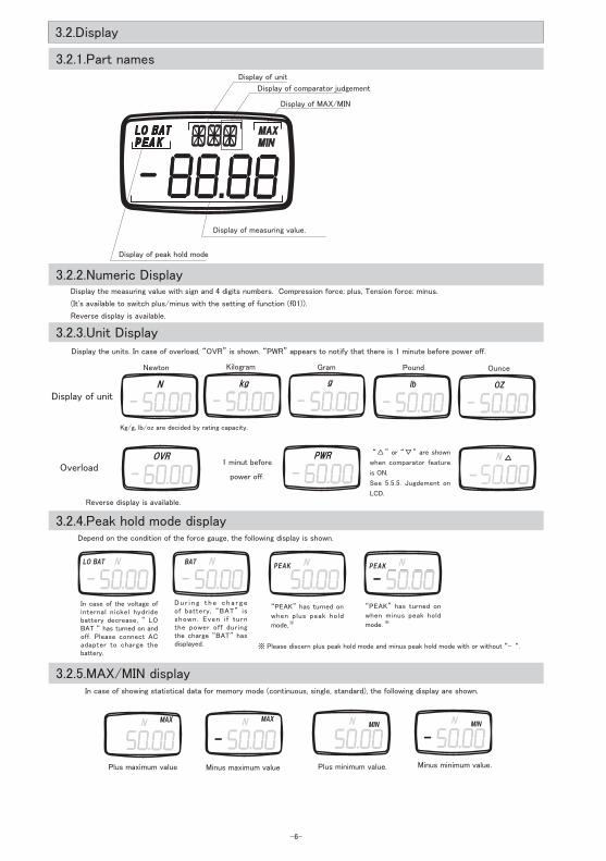
3.2.Display
Display of unit
Display of measuring value.
Display of peak hold mode
Display the measuring value with sign and 4 digits numbers. Compression force: plus, Tension force: minus.
(It's available to switch plus/minus with the setting of function (f01)).
Reverse display is available.
3.2.2.Numeric Display
Display the units. In case of overload, “OVR” is shown. “PWR” appears to notify that there is 1 minute before power off.
3.2.3.Unit Display
Display of unit
Overload
3.2.4.Peak hold mode display
In case of the voltage of internal nickel hydride battery decrease, “ LO BAT “ has turned on and off. Please connect AC adapter to charge the battery.
D u r i n g t h e c h a r g e of battery, “BAT” is shown. Even i f turn the power off during the charge “BAT” has displayed.
“PEAK” has turned on
when plus peak hold
mode, ※
“PEAK” has turned on
when minus peak hold
mode. ※
Newton
Depend on the condition of the force gauge, the following display is shown.
Kilogram Gram
1 minut before
power off.
In case of showing statistical data for memory mode (continuous, single, standard), the following display are shown.
3.2.5.MAX/MIN display
Plus maximum value Minus maximum value Plus minimum value. Minus minimum value.
3.2.1.Part names
Display of MAX/MIN
“△” or “▽” are shown
when comparator feature
is ON.
See 5.5.5. Jugdement on
LCD.
Reverse display is available.
※ Please discern plus peak hold mode and minus peak hold mode with or without “– “.
Display of comparator judgement
Kg/g, lb/oz are decided by rating capacity.
Pound Ounce
-5- -6-
3. Part names and functions
3.1.Main Unit
① Sensor shaft Force bolt (Push/Pull Force)
② Display Display the load and the unit.
③ PEAK key ・ Switch standard measuring mode, + peak hold mode, or – peak hold mode.・ Tracking ON/OFF.・ It is used for comparator/memory setting.
④ UNIT key ・ Switch the unit (N ⇒ Kg ⇒ lb(oz) ⇒ N)・ It is used for reverse the display.・ Tracking ON/OFF.・ It is used for comparator/memory setting.
⑤ ZERO key ・ Tare at standard measuring mode (not display a peak value).・ It is used for function setting.・ Press the ZERO key under the peak hold mode (display the peak value), clear the peak value. In this case, tare does not perform. If you need tare, press the peak key to change into standard measuring mode, then press the Zero key.・ It is used for comparator/memory setting.
⑥ POWER key ・ Press the POWER and release to turn ON/OFF.・ It is used for reverse the display.・ Tracking ON/OFF.・ It is used for comparator/memory setting.
⑦ MEM key ・ Press the MEM key under the standard measuring mode (not display peak value), then measuring value is memorized.・ It is used to recall the memory data, and setting High/Low limits.・ It is used for comparator/memory setting.
⑧ AC adapter port Supply the electricity through the AC adapter.
⑨ Data output port Connect with a PC and a recorder. (RS232C, analog output and so on)
⑩ USB port Connect with a PC. (USB)
⑪ Hanger attachment bolt Attach the hanger with this bolt.
⑫ Threaded hole Use this threaded hole in order to attach the FGP with a stand.
② Display
① Sensor shaft
③ PEAK key
④UNIT key
⑤ZERO key
⑥POWER key
⑦MEM key
Model number
⑫ Threaded hole
⑪ Hanger attachment bolt
⑩USB port
⑧ AC adapter port ⑨ Data output port
PEAK ZERO
MEM
UNIT
REVERSE
-5- -6-
3.2.Display
Display of unit
Display of measuring value.
Display of peak hold mode
Display the measuring value with sign and 4 digits numbers. Compression force: plus, Tension force: minus.
(It's available to switch plus/minus with the setting of function (f01)).
Reverse display is available.
3.2.2.Numeric Display
Display the units. In case of overload, “OVR” is shown. “PWR” appears to notify that there is 1 minute before power off.
3.2.3.Unit Display
Display of unit
Overload
3.2.4.Peak hold mode display
In case of the voltage of internal nickel hydride battery decrease, “ LO BAT “ has turned on and off. Please connect AC adapter to charge the battery.
D u r i n g t h e c h a r g e of battery, “BAT” is shown. Even i f turn the power off during the charge “BAT” has displayed.
“PEAK” has turned on
when plus peak hold
mode, ※
“PEAK” has turned on
when minus peak hold
mode. ※
Newton
Depend on the condition of the force gauge, the following display is shown.
Kilogram Gram
1 minut before
power off.
In case of showing statistical data for memory mode (continuous, single, standard), the following display are shown.
3.2.5.MAX/MIN display
Plus maximum value Minus maximum value Plus minimum value. Minus minimum value.
3.2.1.Part names
Display of MAX/MIN
“△” or “▽” are shown
when comparator feature
is ON.
See 5.5.5. Jugdement on
LCD.
Reverse display is available.
※ Please discern plus peak hold mode and minus peak hold mode with or without “– “.
Display of comparator judgement
Kg/g, lb/oz are decided by rating capacity.
Pound Ounce

-7- -8-
4.2.Attaching measuring adapter
Please select the measuring adapter depend on the measuring purpose.
Screw the adapter until it stops lightly. Do not screw it forcibly in order
not to give the damage to the sensor.
Do not use bruised hook or
deformed hook.
Flat head Cone head Notched head Chisel
Extension rod
Hook
PEAK ZERO
4.Before use
4.1.Charge
Do not charge with non-
attached AC adapter.
Please use AC adapter which supplied with FGP. If you use non-attached AC adapter,
electronic circuit might be broken and fire might happen.
Before the FGP arrive at your hand, nickel hydride battery might discharge electricity.
Please plug attached AC adapter and charge before you use.
① Please connect the attached AC adapter into the AC adapter port of the
body, and plug them into outlet.
・ Start to charge the Nickel hydride battery. After the completion of the
charge, it stops charging automatically by itself.
・ “BAT” will be shown on the LCD display while charging. After complete the
charging, “BAT” will be disappeared from LCD.
・ Charge time: Up to 16 hours at most
・ Operating time: Approx. 8 hours per 1 full charge
② The nickel hydride battery is charged automatically when it
is discharged during the usage of AC adapter.
※ If you charge the battery frequently, its lifetime will be shorten.
When you use the FGP with AC adapter, you should not insert and
remove the AC adapter often.
③ You can measure during the charge.
4.3.Attaching hanger
Please take off the attached hanger bolt. Fit the
square hole of hanger into the salient part of the
case, and then tighten the attached hanger bolt.
Please use the hanger to hang the FGP with a
nail or a winch.
※ Please use the tolerable nail or
winch against the load .
④ When the voltage of nickel hydride battery decline, “LoBAT”
has turned on in the LCD display. Please connect the
AC adapter to charge. (If you leave the FGP with turned
on “LoBAT” , the voltage decline furthermore, and then the
power is turned off compulsory.)
Hanger attachement bolt
Hanger
AC adapter port
Please attached the hunger according to need.
Do not screw the attachment
in forcebly.
-7- -8-
Key operation Display
Turn the power off
PEAK ZERO
MEM
UNIT
① Hold down PEAK and UNIT key,
② Press POWER key.
PEAK ZERO
MEM
UNIT
Release POWER key only.
4.4.Tracking
A load cell of strain gauge is used for FGP as a load sensing. By using this sensor, the measuring value is slightly changed due to temperature
and so on, but tracking is able to cancel this slightly change by the software. When you measure very minute forces, measuring value error
might happen due to the tracking. In this case, you may turn off the tracking function.
When the power off, while hold down the PEAK key and UNIT key simultaneously, press and release the POWER key (release the PEAK key and
UNIT key after the value is appeard in the display more than 1 second), you can switch the tracking ON/OFF.
Display force gauge model
Tracking OFF
Tracking ON
Standard measuring mode
Please release the PEAK
key and UNIT key after
the value is appeared in
the display more than 1
second.
Tracking ON
Tracking OFF
4.5.Function setting
Key operation DisplayTurn the power off
PEAK ZERO
MEM
UNIT
① Hold down ZERO key,
② Press POWER key.
PEAK ZERO
MEM
UNIT
Release POWER key only.
Display force gauge model Display function mode (f01)
Please release the ZERO
key after the value is
appeared in the display
more than 1 second.
The following setting items in function mode.
Item Unit Set contents Default factory setting
Display sign f01 -0001(minus), 0001 (plus) 0001
Display update time f02 1、 2、 3、 5、 10、 20 (times/second) 3
Auto power off f03 10 (10 minutes )、 oFF (not valid) 10
RS-232C baud rate f04 2400、 4800、 9600、 19200 (bps) 2400
Measuring filter f05 3、 20、 150 (msec) 3
External output f06 ovEr、 Hi-Lo ovEr
Turn power off, then press POWER key, you can confirm the condition of
the present tracking.
①
②
①
②

-7- -8-
4.2.Attaching measuring adapter
Please select the measuring adapter depend on the measuring purpose.
Screw the adapter until it stops lightly. Do not screw it forcibly in order
not to give the damage to the sensor.
Do not use bruised hook or
deformed hook.
Flat head Cone head Notched head Chisel
Extension rod
Hook
PEAK ZERO
4.Before use
4.1.Charge
Do not charge with non-
attached AC adapter.
Please use AC adapter which supplied with FGP. If you use non-attached AC adapter,
electronic circuit might be broken and fire might happen.
Before the FGP arrive at your hand, nickel hydride battery might discharge electricity.
Please plug attached AC adapter and charge before you use.
① Please connect the attached AC adapter into the AC adapter port of the
body, and plug them into outlet.
・ Start to charge the Nickel hydride battery. After the completion of the
charge, it stops charging automatically by itself.
・ “BAT” will be shown on the LCD display while charging. After complete the
charging, “BAT” will be disappeared from LCD.
・ Charge time: Up to 16 hours at most
・ Operating time: Approx. 8 hours per 1 full charge
② The nickel hydride battery is charged automatically when it
is discharged during the usage of AC adapter.
※ If you charge the battery frequently, its lifetime will be shorten.
When you use the FGP with AC adapter, you should not insert and
remove the AC adapter often.
③ You can measure during the charge.
4.3.Attaching hanger
Please take off the attached hanger bolt. Fit the
square hole of hanger into the salient part of the
case, and then tighten the attached hanger bolt.
Please use the hanger to hang the FGP with a
nail or a winch.
※ Please use the tolerable nail or
winch against the load .
④ When the voltage of nickel hydride battery decline, “LoBAT”
has turned on in the LCD display. Please connect the
AC adapter to charge. (If you leave the FGP with turned
on “LoBAT” , the voltage decline furthermore, and then the
power is turned off compulsory.)
Hanger attachement bolt
Hanger
AC adapter port
Please attached the hunger according to need.
Do not screw the attachment
in forcebly.
-7- -8-
Key operation Display
Turn the power off
PEAK ZERO
MEM
UNIT
① Hold down PEAK and UNIT key,
② Press POWER key.
PEAK ZERO
MEM
UNIT
Release POWER key only.
4.4.Tracking
A load cell of strain gauge is used for FGP as a load sensing. By using this sensor, the measuring value is slightly changed due to temperature
and so on, but tracking is able to cancel this slightly change by the software. When you measure very minute forces, measuring value error
might happen due to the tracking. In this case, you may turn off the tracking function.
When the power off, while hold down the PEAK key and UNIT key simultaneously, press and release the POWER key (release the PEAK key and
UNIT key after the value is appeard in the display more than 1 second), you can switch the tracking ON/OFF.
Display force gauge model
Tracking OFF
Tracking ON
Standard measuring mode
Please release the PEAK
key and UNIT key after
the value is appeared in
the display more than 1
second.
Tracking ON
Tracking OFF
4.5.Function setting
Key operation DisplayTurn the power off
PEAK ZERO
MEM
UNIT
① Hold down ZERO key,
② Press POWER key.
PEAK ZERO
MEM
UNIT
Release POWER key only.
Display force gauge model Display function mode (f01)
Please release the ZERO
key after the value is
appeared in the display
more than 1 second.
The following setting items in function mode.
Item Unit Set contents Default factory setting
Display sign f01 -0001(minus), 0001 (plus) 0001
Display update time f02 1、 2、 3、 5、 10、 20 (times/second) 3
Auto power off f03 10 (10 minutes )、 oFF (not valid) 10
RS-232C baud rate f04 2400、 4800、 9600、 19200 (bps) 2400
Measuring filter f05 3、 20、 150 (msec) 3
External output f06 ovEr、 Hi-Lo ovEr
Turn power off, then press POWER key, you can confirm the condition of
the present tracking.
①
②
①
②

-9- -10-
Key operation Display
PEAK ZERO
MEM
UNIT
Each time to press UNIT
ZERO Register the all setting, and then move to the standard measuring mode.
PEAK Reserve the change, and then move to f03.
Key operation Display
PEAK ZERO
MEM
UNIT
Each time to press UNIT
ZERO Register the all setting, and then move to the standard measuring mode.
PEAK Reserve the change, and then move to f02.
It's available to set the sign (plus or minus) of measuring value for pushing the sensor shaft.
Select the sign by use of UNIT key / Press the PEAK key to move ahead.
Minus Plus
4.5.2.Display update time: f02It's available to set the display update time for 1 time/second, 2 times/second, 3 times/second, 5 times/second, 10 times/second and 20
times/second. After the setting, the averaging value in display update time is shown every display update time.
Press the UNIT key to choose the display update time (1、 2、 3、 5、 10、 20 (times/second) ) / Press the PEAK key to move ahead
1 time/sec 2 times/sec 3 times/sec
5 times/sec10 times/sec20 times/sec
Key operation Display
PEAK ZERO
MEM
UNIT
Each time to press UNIT
ZERO Register the all setting, and then move to the standard measuring mode.
PEAK Reserve the change, and then move to f04.
4.5.3.Auto power off: f03If the gauge is on and there is no activity for 10 minutes*, the unit automatically powers off to conserve battery charge (In case of
connected with AC adapter, Auto power off function does not work). “PWR” appears to notify that there is 1 minute before power off.
Press the UNIT key to switch the auto power off / Press the PEAK key to move ahead
※ There is no key operation, RS-232C communication, USB communication, change of measuring value.
Auto power off, 10 min Auto power off is not available.
4.5.1.Sign: f01
-9- -10-
4.5.4.Baud rate of RS-232C : f04It's available to set the baud rate of RS-232C.
Press the UNIT key to switch the Baud rate (2400、 4800、 9600、 19200(bps)) / Press PEAK key to move ahead.
Key operation Display
PEAK ZERO
MEM
UNIT
Each time to press UNIT
ZERO Register the all setting, and then move to the standard measuring mode.
PEAK Reserve the change, and then move to f05.
2400bps 4800bps 9600bps 19200bps
4.5.5.Measuring filter : f05It's available to set 3 types of filters as follows.
Press UNIT key to switch (response time 3 (msec)、 20 (msec)、 150 (msec)) ※Press PEAK key to move ahead
Key operation Display
PEAK ZERO
MEM
UNIT
Each time to press UNIT
ZERO Register the all setting, and then move to the standard measuring mode.
PEAK Reserve the change, and then move to f06.
Response time 3msec Response time 20msec Response time 150msec
※ Filter response time show 90% of step input.
Depend on the filter response, sampling period
and analog output update period is decided.
Key operation Display
PEAK ZERO
MEM
UNIT
Each time to press UNIT
ZERO Register the all setting, and then move to the standard measuring mode.
PEAK Reserve the change, and then move to f01.
4.5.6.External output : f06It's available to chose external output (overload output or comparator output).
Press UNIT key to switch external output. / Press PEAK key to move f01.
Press ZERO key to memorize the set value and come back from function mode to standard measuring mode.
In order to cancel the change of function mode, press POWER key, then turn the POWER off.
4.5.7.Function mode-end
※ When you set “ovEr” , both the display of comparator judgement and I/O output are not performed.
Overload output Comparator output
Input (change of actual load)
Measuring value
90% response time
90%
Filter response Sampling period ・ Analog output update period
3msec 1msec
20msec 1msec
150msec 6.7msec

-11- -12-
Key Operation
POWER Turn the POWER ON/OFF
ZERO Tare (Peak reset at the PEAK Hold mode)
PEAK Standard measuring mode / Plus peak hold mode / Minus peak hold mode
UNIT Change the unit
MEM Store the measuring data into memory
Key Operation How to operate
PEAK + UNITPOWER
Tracking
ON / OFF
Turn POWER off. Press PEAK key and UNIT key simultaneously and hold, then press and
release POWER key (release the PEAK key and UNIT key after the value is appeared in
the display more than 1 second.)
ZEROPOWER
Function mode
Turn POWER off. Press ZERO key and hold, then press POWER key and release (release
ZERO key after the value is appeared in the display more than 1 second).
Function mode;
UNIT : Change the setting content
PEAK : Switch the function
ZERO : Register the setting content
UNITPOWER
Reverse displayTurn POWER off. Press UNIT key and hold, then press POWER key and release (release
the UNIT key after the value is appeard in the display more than 1 second.)
MEMPOWER
Display memory data
Turn POWER off. Press MEM key and hold, then press POWER key and release (release
MEM key after the value is appeared in the display more than 1 second.)
Display memory data;
UNIT : Display the statistical data.
PEAK : Memory data display end.
ZERO : Delete one memory data.
Hold ZERO key to delete all data
MEM : Next memory data
PEAKPOWER
Comparator
memory mode setting
Turn POWER off. Press PEAK key and hold, then press POWER key and release.
In this setting;
UNIT : Change sign, number and memory mode
PEAK : Change the setting content
ZERO : Shift the digit
MEM : Register the setting content
5.Feature and Operation
5.1.Overview of operation1) Basic operation
2) Special operation
Key operation DisplayTurn the power off
PEAK ZERO
MEM
UNIT
① Hold down UNIT key
② Press POWER key.
PEAK ZERO
MEM
UNIT
Release POWER key only.
In the case you attach FGP with a stand, display of the value and the units can be reversed in order to read the display easily.
Turn POWER off. Press the UNIT key and hold, then press POWER key and release (release UNIT key after the value is appeared in the display
more than 1 second). Then you can reverse the disply.
4.6.Reverse the display
Please re lease the UNIT key after the value is appeared in the display more than 1 second.
Display force gauge model
Standard display
Standard measuring mode
Reverse display
Reverse disply Standard display
① ②
-11- -12-
It's available to measure the compression and tension force. Measuring value is appeared at all times.
1) Press POWER key and release ( Turn POWER on after release)
2) Press ZERO key to tare.
Displayed measuring value is averaged out the sampling value (every 1 msec * ) per display update time.
Display update time of default factory setting is 3 times/second. In order to increase the display response against the change of measuring
value, you may change the set value of display update time.
You can increase this time up to 20 times/second (regarding the change of display update time, please refer “4.5.2. Display update time” .)
To change the display units, just press UNIT and the units will change every time the button is pressed.
N→ kg (g) → lb (oz) → N
Press ZERO key to reset the measuring value. Please press the ZERO key before starting the measurement in order not to change the starting
display value because of the own weight or measuring direction or weight of measuring fixture.
Measuring range is from maximum pulling load to maximum compression load. When measuring range is over, “OVR” is displayed.
Press the ZERO key under the plus peak hold mode or minus peak hold mode, plus peak value or minus peak value is cleared. At the plus peak
hold mode and minus peak hold mode, tare does not performed even if press and release ZERO key.
When turning POWER on, tare is automatically performed (if you turn POWER on during the getting load, display becomes “0” and you cannot
measure accurate value).
5.2.1Standard measuring mode
5.3.Change display unit
5.4.Tare
5.2.2 Peak hold modeDisplay peak measuring value. Sampling time is 1ms. *
Press PEAK key to change standard measuring mode, Plus peak hold mode and Minus peak hold mode.
Under the plus peak hold mode, “PEAK” is appeared.
Under the minus peak hold mode, “PEAK” and “- “ (minus) are appeared.
Key operation Display
PEAK ZERO
MEM
UNIT
Each time to press PEAK
Standard measuring mode Plus peak hold mode Minus peak hold mode
Under the plus peak hold mode and minus peak hold mode, press ZERO key to clear the peak value (Tare is not performed).
5.2.Measuring Mode
There are standard measuring mode and peak hold mode in the measuring mode.
Key operation Display
PEAK ZERO
MEM
UNIT
Press and release
Display force gauge model Standard measuring modeDisplay tracking ON/OFF
※ It is depend on the setting of filter (f05). Please refer “4.5.5. Measuring filter” .
※ It is depend on the setting of filter (f05). Pleae refer “4.5.5. Measuring filter” .

-11- -12-
Key Operation
POWER Turn the POWER ON/OFF
ZERO Tare (Peak reset at the PEAK Hold mode)
PEAK Standard measuring mode / Plus peak hold mode / Minus peak hold mode
UNIT Change the unit
MEM Store the measuring data into memory
Key Operation How to operate
PEAK + UNITPOWER
Tracking
ON / OFF
Turn POWER off. Press PEAK key and UNIT key simultaneously and hold, then press and
release POWER key (release the PEAK key and UNIT key after the value is appeared in
the display more than 1 second.)
ZEROPOWER
Function mode
Turn POWER off. Press ZERO key and hold, then press POWER key and release (release
ZERO key after the value is appeared in the display more than 1 second).
Function mode;
UNIT : Change the setting content
PEAK : Switch the function
ZERO : Register the setting content
UNITPOWER
Reverse displayTurn POWER off. Press UNIT key and hold, then press POWER key and release (release
the UNIT key after the value is appeard in the display more than 1 second.)
MEMPOWER
Display memory data
Turn POWER off. Press MEM key and hold, then press POWER key and release (release
MEM key after the value is appeared in the display more than 1 second.)
Display memory data;
UNIT : Display the statistical data.
PEAK : Memory data display end.
ZERO : Delete one memory data.
Hold ZERO key to delete all data
MEM : Next memory data
PEAKPOWER
Comparator
memory mode setting
Turn POWER off. Press PEAK key and hold, then press POWER key and release.
In this setting;
UNIT : Change sign, number and memory mode
PEAK : Change the setting content
ZERO : Shift the digit
MEM : Register the setting content
5.Feature and Operation
5.1.Overview of operation1) Basic operation
2) Special operation
Key operation DisplayTurn the power off
PEAK ZERO
MEM
UNIT
① Hold down UNIT key
② Press POWER key.
PEAK ZERO
MEM
UNIT
Release POWER key only.
In the case you attach FGP with a stand, display of the value and the units can be reversed in order to read the display easily.
Turn POWER off. Press the UNIT key and hold, then press POWER key and release (release UNIT key after the value is appeared in the display
more than 1 second). Then you can reverse the disply.
4.6.Reverse the display
Please re lease the UNIT key after the value is appeared in the display more than 1 second.
Display force gauge model
Standard display
Standard measuring mode
Reverse display
Reverse disply Standard display
① ②
-11- -12-
It's available to measure the compression and tension force. Measuring value is appeared at all times.
1) Press POWER key and release ( Turn POWER on after release)
2) Press ZERO key to tare.
Displayed measuring value is averaged out the sampling value (every 1 msec * ) per display update time.
Display update time of default factory setting is 3 times/second. In order to increase the display response against the change of measuring
value, you may change the set value of display update time.
You can increase this time up to 20 times/second (regarding the change of display update time, please refer “4.5.2. Display update time” .)
To change the display units, just press UNIT and the units will change every time the button is pressed.
N→ kg (g) → lb (oz) → N
Press ZERO key to reset the measuring value. Please press the ZERO key before starting the measurement in order not to change the starting
display value because of the own weight or measuring direction or weight of measuring fixture.
Measuring range is from maximum pulling load to maximum compression load. When measuring range is over, “OVR” is displayed.
Press the ZERO key under the plus peak hold mode or minus peak hold mode, plus peak value or minus peak value is cleared. At the plus peak
hold mode and minus peak hold mode, tare does not performed even if press and release ZERO key.
When turning POWER on, tare is automatically performed (if you turn POWER on during the getting load, display becomes “0” and you cannot
measure accurate value).
5.2.1Standard measuring mode
5.3.Change display unit
5.4.Tare
5.2.2 Peak hold modeDisplay peak measuring value. Sampling time is 1ms. *
Press PEAK key to change standard measuring mode, Plus peak hold mode and Minus peak hold mode.
Under the plus peak hold mode, “PEAK” is appeared.
Under the minus peak hold mode, “PEAK” and “- “ (minus) are appeared.
Key operation Display
PEAK ZERO
MEM
UNIT
Each time to press PEAK
Standard measuring mode Plus peak hold mode Minus peak hold mode
Under the plus peak hold mode and minus peak hold mode, press ZERO key to clear the peak value (Tare is not performed).
5.2.Measuring Mode
There are standard measuring mode and peak hold mode in the measuring mode.
Key operation Display
PEAK ZERO
MEM
UNIT
Press and release
Display force gauge model Standard measuring modeDisplay tracking ON/OFF
※ It is depend on the setting of filter (f05). Please refer “4.5.5. Measuring filter” .
※ It is depend on the setting of filter (f05). Pleae refer “4.5.5. Measuring filter” .

-13- -14-
Key operation Status
PEAK Move to LO limit setting.
MEMRegister the setting, then move
to standard measuring mode.
Turn power off without any change.
Key operation DisplayTurn the power off
PEAK ZERO
MEM
UNIT
① Hold down PEAK key
② Press POWER key
PEAK ZERO
MEM
UNIT
Release POWER key only
5.5.Comparator
Compare HI / LO limit which you entered to measuring value, then result is appeared in the display.
In addition, output signal of the result is available with data output port.
In order to active comparator function, you have to set “Hi-Lo” at “External output (f06)” at function setting. (When you set “ovEr” at the
External output (f06), result does not appear and output signal is not performed.)
5.5.1.Compatrator
5.5.2.How to enter Comparator / Memory setting modeTurn POWER off, press PEAK key and hold, then press POWER key and release (release PEAK key after the value is displayed more than 1
second).
Display force gauge modelPEAK
PEAK
Comparator HI limit setting
Comparator LO limit setting
Memory mode setting
PEAK
There are following setting items for comparator /memory setting mode.
Item Display Content of setting Default factory setting
Comparator HI limit HI Set the comparator HI limit※ 0
Comparator LO limit LO Set the comparator LO limit※ 0
Memory mode setting MEM Set the memory mode (single mode, continuous mode, standard mode) Std
When you set “0” at both HI limit and LOW limit, comparater function does not work.
5.5.3.Setting HI limit(1) Press the UNIT key then all 4 digits turn on and off. Press the UNIT key once more, you can chose sign (plus or minus).
(2) Choose 0,1,2,3,4,5,6,7,8,9 at 4 ~ 1 digit (when you prees UNIT key at 9, it turns 0). Press ZERO key to move right one digit.
In this case, chosen number is displayed with unit which is chosen at standard measuring mode. (When you change the
unit at standard measuring mode after the setting of HI limit, the conversion of the unit for HI limit value is not performed.
After the change of the unit, please set the HI limit again.)
(3) Press PEAK key, then move to the setting of comparator LO limit
(4) Press MEM key, then setting value is registerd and move to standard measuring mode.
(5) When you set both HI and LO limit with “0” , comparater function does not work.
Key operation Status Display
UNIT Choose sign
ZEROMove to next
digit (right)
UNIT Change numeric
Press ZERO key
t o move r i g h t
digit by one digit
When you press ZERO key at first digit, move to 5th digit.
Please re lease the PEAK key after the value is appeared in the display more than 1 second.
You can set the value regardless of rating capacity. In the case you set the value which is out of the
range for rating capacity, comparator function might not work properly.
NOTICE
①
②
-13- -14-
5.5.4.Setting LO limit
(1) Press PEAK key during comparator HI limit setting, then move to LO limit setting.
(2) Setting way is the same as the comparator HI limit setting.
(3) Press MEM key, then setting value is registered, and move to standard measuring mode.
(4) When you set HI and LO limit with “0” , comparator function does not work.
Key operation State
PEAK Move to memory mode.
MEMRegister the setting, then move
to standard measuring mode.
Turn power off without any change.
LO limit setting mode
5.5.5.Judgement on LCD
Compare the measuring value to comparator HI / LO limit value, then show △▽ after the unit.
“△” means measuring value > HI limit
“▽” means measuring value < LO limit
Data ≦ HI limit
Data ≧ LO limit
Data > HI limit
Data ≧ LO limit
Data ≦ HI limit
Data < LO limit
Data > HI limit
Data < LO limit
In case of N (unit)
※ In order to active the display of comparator judgement, you have to set ” Hi-Lo” at function mode ” External output (f06)” .
5.5.6.Output signal of judgement
Compare the measuring value to comparator HI / LO limit value, then the signal of comparator judgement
will be outputted through the data output port.
Measuring value > HI limit value ⇒ Turn on output signal of comparator HI limit.
Measuring value < LO limit value ⇒ Turn on output signal of comparator LO limit.
5.6.Memory
There are 3 modes at memory mode as follows.
Continuous memoryMemorize 1000 data at maximum which is measured between press MEM key and press MEM key next time. In
addition, statistical data of memory data (plus maximum value, minus maximum value, plus minimum value, minus
minimum value, plus peak value, minus peak value, average value, standard deviation) is displayed.
Single memory
Every time press MEM key, display value (under the standard measuring mode: measuring value, under ths peak
hold mode: peak value) is memorized at this point up to 100 data. In addition, statistical data of memory data
(plus maximum value, minus maximum value, plus minimum value, minus minimum value, average value, standard
deviation) is displayed.
Standard memoryMemorize statistical data (plus maximum value, minus maximum value, plus minimum value, minus minimum value,
plus peak value, minus peak value) and last measuring data which is measured between press MEM key and
press MEM key next time. Memoraize up to 50data.
※ In order to active output signal of comparator judgement, please set “Hi-Lo” at function mode ” External output (f06)” .
Relation between judgement and display is as follows.

-13- -14-
Key operation Status
PEAK Move to LO limit setting.
MEMRegister the setting, then move
to standard measuring mode.
Turn power off without any change.
Key operation DisplayTurn the power off
PEAK ZERO
MEM
UNIT
① Hold down PEAK key
② Press POWER key
PEAK ZERO
MEM
UNIT
Release POWER key only
5.5.Comparator
Compare HI / LO limit which you entered to measuring value, then result is appeared in the display.
In addition, output signal of the result is available with data output port.
In order to active comparator function, you have to set “Hi-Lo” at “External output (f06)” at function setting. (When you set “ovEr” at the
External output (f06), result does not appear and output signal is not performed.)
5.5.1.Compatrator
5.5.2.How to enter Comparator / Memory setting modeTurn POWER off, press PEAK key and hold, then press POWER key and release (release PEAK key after the value is displayed more than 1
second).
Display force gauge modelPEAK
PEAK
Comparator HI limit setting
Comparator LO limit setting
Memory mode setting
PEAK
There are following setting items for comparator /memory setting mode.
Item Display Content of setting Default factory setting
Comparator HI limit HI Set the comparator HI limit※ 0
Comparator LO limit LO Set the comparator LO limit※ 0
Memory mode setting MEM Set the memory mode (single mode, continuous mode, standard mode) Std
When you set “0” at both HI limit and LOW limit, comparater function does not work.
5.5.3.Setting HI limit(1) Press the UNIT key then all 4 digits turn on and off. Press the UNIT key once more, you can chose sign (plus or minus).
(2) Choose 0,1,2,3,4,5,6,7,8,9 at 4 ~ 1 digit (when you prees UNIT key at 9, it turns 0). Press ZERO key to move right one digit.
In this case, chosen number is displayed with unit which is chosen at standard measuring mode. (When you change the
unit at standard measuring mode after the setting of HI limit, the conversion of the unit for HI limit value is not performed.
After the change of the unit, please set the HI limit again.)
(3) Press PEAK key, then move to the setting of comparator LO limit
(4) Press MEM key, then setting value is registerd and move to standard measuring mode.
(5) When you set both HI and LO limit with “0” , comparater function does not work.
Key operation Status Display
UNIT Choose sign
ZEROMove to next
digit (right)
UNIT Change numeric
Press ZERO key
t o move r i g h t
digit by one digit
When you press ZERO key at first digit, move to 5th digit.
Please re lease the PEAK key after the value is appeared in the display more than 1 second.
You can set the value regardless of rating capacity. In the case you set the value which is out of the
range for rating capacity, comparator function might not work properly.
NOTICE
①
②
-13- -14-
5.5.4.Setting LO limit
(1) Press PEAK key during comparator HI limit setting, then move to LO limit setting.
(2) Setting way is the same as the comparator HI limit setting.
(3) Press MEM key, then setting value is registered, and move to standard measuring mode.
(4) When you set HI and LO limit with “0” , comparator function does not work.
Key operation State
PEAK Move to memory mode.
MEMRegister the setting, then move
to standard measuring mode.
Turn power off without any change.
LO limit setting mode
5.5.5.Judgement on LCD
Compare the measuring value to comparator HI / LO limit value, then show △▽ after the unit.
“△” means measuring value > HI limit
“▽” means measuring value < LO limit
Data ≦ HI limit
Data ≧ LO limit
Data > HI limit
Data ≧ LO limit
Data ≦ HI limit
Data < LO limit
Data > HI limit
Data < LO limit
In case of N (unit)
※ In order to active the display of comparator judgement, you have to set ” Hi-Lo” at function mode ” External output (f06)” .
5.5.6.Output signal of judgement
Compare the measuring value to comparator HI / LO limit value, then the signal of comparator judgement
will be outputted through the data output port.
Measuring value > HI limit value ⇒ Turn on output signal of comparator HI limit.
Measuring value < LO limit value ⇒ Turn on output signal of comparator LO limit.
5.6.Memory
There are 3 modes at memory mode as follows.
Continuous memoryMemorize 1000 data at maximum which is measured between press MEM key and press MEM key next time. In
addition, statistical data of memory data (plus maximum value, minus maximum value, plus minimum value, minus
minimum value, plus peak value, minus peak value, average value, standard deviation) is displayed.
Single memory
Every time press MEM key, display value (under the standard measuring mode: measuring value, under ths peak
hold mode: peak value) is memorized at this point up to 100 data. In addition, statistical data of memory data
(plus maximum value, minus maximum value, plus minimum value, minus minimum value, average value, standard
deviation) is displayed.
Standard memoryMemorize statistical data (plus maximum value, minus maximum value, plus minimum value, minus minimum value,
plus peak value, minus peak value) and last measuring data which is measured between press MEM key and
press MEM key next time. Memoraize up to 50data.
※ In order to active output signal of comparator judgement, please set “Hi-Lo” at function mode ” External output (f06)” .
Relation between judgement and display is as follows.

-15- -16-
[Definisions of the terms]
Measuring value: Displayed value which is per display update time at standard measuring mode.
Plus maximum value (+MAX): Maximum value at plus side which is measured within memory measuring interval.
Minus maximum value (-MAX): Maximum value at minus side which is measured within memory measuring interval.
Plus minimum value (+MIN): Minimum value at plus side which is measured within memory measuring interval.
Minus minimum value (-MIN): Minimum value at minus side which is measured within memory measuring interval.
Example of +MAX, -MAX, +MIN, -MIN (Continuous memory mode)
[Ex1]
[Ex2]
[Ex3]
+MAX
+MAX
+MIN (0), -MIN (-0)
+MIN (0), +MAX (0)
-MAX
-MAX
+MIN
-MIN
Start memory
Start memory
Start memory
Finish memory
Finish memory
Finish memory
+
+
+
-
-
-
0
0
0
-MIN (-0), -MAX (-0)
Average value (AVE) : Average value of measuring value which is measured within memory measuring interval.Σ X i/n
Standard deviation (DEV) : Standard deviation of measuring value which is measured within memory measuring interval. Σ( X i-X )2/n
Plus peak value : Plus peak value within memory measuring interval (Maximum value within sampling interval 1000 times/secnd).
Minus peak value : Minus peak value within memory measuring interval (Mnimum value within sampling interval 1000 times/second)
Last measuring value (LST) : Value which is measured in the end of memory measuring interval.
-15- -16-
Key Operation Display
Turn power off.
PEAK ZERO
MEM
UNIT
① Hold down PEAK key
② Press POWER key
PEAK ZERO
MEM
UNIT
Release POWER key only
5.6.1.Setting memory mode
Turn the POWER off. Press PEAK key and hold, then press POWER key. Comparator HI limit setting turns on, then press PEAK key twice.
Memory setting mode turns on.
Display force gauge model PEAK
PEAK
Comparator HI limit setting
Comparator LO limit setting
PEAK
There are following setting items for comparator ・ memory setting mode.
Item Display Content Default factory setting
Comparator HI limit setting HI Set comparator HI limit ※ 0
Comparator LO limit setting LO Set comparator LO limit ※ 0
Memory mode setting MEM Set memory mode (Single mode, Continuous mode, Standard mode) Std
※ When you set “0” at both HI limit and LO limit, comparator function does not work.
At memory mode setting, you can set single memory, continuous memory, standard memory.
(1) Switch memory mode (SinG (single memory mode), Cont (continuous memory mode), Std (standard memory mode)) by UNIT key.
(2) Press PEAK key to move comparator upper limit setting.
(3) Press MEM key to register the setting, and move to standard display.
MEM
Register the
setting, and then
move to standard
measuring mode.
UNIT
UNIT
Single
memory
Continuous
memory
Standard
memory
Memory mode setting
Please release the PEAK
key after the value is
appeared in the display
more than 1 second.
①
②
UNIT

-15- -16-
[Definisions of the terms]
Measuring value: Displayed value which is per display update time at standard measuring mode.
Plus maximum value (+MAX): Maximum value at plus side which is measured within memory measuring interval.
Minus maximum value (-MAX): Maximum value at minus side which is measured within memory measuring interval.
Plus minimum value (+MIN): Minimum value at plus side which is measured within memory measuring interval.
Minus minimum value (-MIN): Minimum value at minus side which is measured within memory measuring interval.
Example of +MAX, -MAX, +MIN, -MIN (Continuous memory mode)
[Ex1]
[Ex2]
[Ex3]
+MAX
+MAX
+MIN (0), -MIN (-0)
+MIN (0), +MAX (0)
-MAX
-MAX
+MIN
-MIN
Start memory
Start memory
Start memory
Finish memory
Finish memory
Finish memory
+
+
+
-
-
-
0
0
0
-MIN (-0), -MAX (-0)
Average value (AVE) : Average value of measuring value which is measured within memory measuring interval.Σ X i/n
Standard deviation (DEV) : Standard deviation of measuring value which is measured within memory measuring interval. Σ( X i-X )2/n
Plus peak value : Plus peak value within memory measuring interval (Maximum value within sampling interval 1000 times/secnd).
Minus peak value : Minus peak value within memory measuring interval (Mnimum value within sampling interval 1000 times/second)
Last measuring value (LST) : Value which is measured in the end of memory measuring interval.
-15- -16-
Key Operation Display
Turn power off.
PEAK ZERO
MEM
UNIT
① Hold down PEAK key
② Press POWER key
PEAK ZERO
MEM
UNIT
Release POWER key only
5.6.1.Setting memory mode
Turn the POWER off. Press PEAK key and hold, then press POWER key. Comparator HI limit setting turns on, then press PEAK key twice.
Memory setting mode turns on.
Display force gauge model PEAK
PEAK
Comparator HI limit setting
Comparator LO limit setting
PEAK
There are following setting items for comparator ・ memory setting mode.
Item Display Content Default factory setting
Comparator HI limit setting HI Set comparator HI limit ※ 0
Comparator LO limit setting LO Set comparator LO limit ※ 0
Memory mode setting MEM Set memory mode (Single mode, Continuous mode, Standard mode) Std
※ When you set “0” at both HI limit and LO limit, comparator function does not work.
At memory mode setting, you can set single memory, continuous memory, standard memory.
(1) Switch memory mode (SinG (single memory mode), Cont (continuous memory mode), Std (standard memory mode)) by UNIT key.
(2) Press PEAK key to move comparator upper limit setting.
(3) Press MEM key to register the setting, and move to standard display.
MEM
Register the
setting, and then
move to standard
measuring mode.
UNIT
UNIT
Single
memory
Continuous
memory
Standard
memory
Memory mode setting
Please release the PEAK
key after the value is
appeared in the display
more than 1 second.
①
②
UNIT

-17- -18-
5.6.2.Storing dataStore the data at setting memory mode (single memory, continuous memory, standard memory).
5.6.2.1.Store the data (Continuous memory mode)(1) During the standard measuring mode, please press MEM key. Then “M” blink, start the record. Press MEM key, measurement is finished,
and then display of the unit is changed from M into the unit.
(2) When the memory number arrive at 1000 during the record, “FULL” appear at the display of measuring value, then record is finished
and move to standard measuring mode.
Key operation Status Display(""means blinking)
MEM
Standard
measuring
mode
- Registering the data
MEM The record is finished
When amount of memory number arrive at 1000
5.6.2.2.Store the data (Single memory mode)(1) During the standard measuring mode, please press MEM key. Then “M” turn on at the unit display and the present display (one data) is recorded.
(2) If 100 data are already recorded, “FULL” appears for 1 second at the value display. Then move to standard measuring mode.
Key operation Status Display
MEM
Standard
measuring
mode
- Registering the data
When amount of memory number arrive at 100
5.6.2.3.Store the data (Standard memory mode)
Press MEM key during the standard measuring, then “M” blink at the unit display, start the record. Press
MEM key again to finish measurement, then display of the unit return to the unit display.
Key operation Status Display(""means blinking)
MEM
Standard
measuring
mode
- Registering the data
MEM The record is finished
When amount of memory number arrive at 50
-17- -18-
Key operation Display
Turn power off.
PEAK ZERO
MEM
UNIT
① Hold down MEN key
② Press POWER key
PEAK ZERO
MEM
UNIT
Release POWER key only
ZERO Delete the data when last memory data is displayed.
UNIT Display the statistics memory data.
PEAK Output the memory data with RS-232C, and then move to standard measuring mode.
Finish display of the memory data. (Turn the power off)
5.7.Recalling memory data
5.7.1.Continuous memory mode
(1) Turn the POWER off. Press MEM key and hold, then press and release POWER key (release MEM key after the value appear in
the display more than 1 second), then move to display measuring memory data.
(2) Start to display from the last memory data which is recorded. Memory number and data appear one after the other.
(3) Press MEM key to display previous memory number (when memory number is 1, move to last memory data number).
(4) Press PEAK key to output with RS-232C (regarding output format, please dawnload “FGP series RS-232C communication command
list” from our web site. And, please refer “6.2.2. RS232C communication command” for the detail.). Move to standard measuring mode.
Last memory number Last memory number-1 Memory number 1MEM MEM
Display one after the other Display one after the other Display one
after the other
Please release the MEN
key after the value is
appeared in the display
more than 1 second.
5.7.1.1.Measuring memory data
①
②
MEM

-17- -18-
5.6.2.Storing dataStore the data at setting memory mode (single memory, continuous memory, standard memory).
5.6.2.1.Store the data (Continuous memory mode)(1) During the standard measuring mode, please press MEM key. Then “M” blink, start the record. Press MEM key, measurement is finished,
and then display of the unit is changed from M into the unit.
(2) When the memory number arrive at 1000 during the record, “FULL” appear at the display of measuring value, then record is finished
and move to standard measuring mode.
Key operation Status Display(""means blinking)
MEM
Standard
measuring
mode
- Registering the data
MEM The record is finished
When amount of memory number arrive at 1000
5.6.2.2.Store the data (Single memory mode)(1) During the standard measuring mode, please press MEM key. Then “M” turn on at the unit display and the present display (one data) is recorded.
(2) If 100 data are already recorded, “FULL” appears for 1 second at the value display. Then move to standard measuring mode.
Key operation Status Display
MEM
Standard
measuring
mode
- Registering the data
When amount of memory number arrive at 100
5.6.2.3.Store the data (Standard memory mode)
Press MEM key during the standard measuring, then “M” blink at the unit display, start the record. Press
MEM key again to finish measurement, then display of the unit return to the unit display.
Key operation Status Display(""means blinking)
MEM
Standard
measuring
mode
- Registering the data
MEM The record is finished
When amount of memory number arrive at 50
-17- -18-
Key operation Display
Turn power off.
PEAK ZERO
MEM
UNIT
① Hold down MEN key
② Press POWER key
PEAK ZERO
MEM
UNIT
Release POWER key only
ZERO Delete the data when last memory data is displayed.
UNIT Display the statistics memory data.
PEAK Output the memory data with RS-232C, and then move to standard measuring mode.
Finish display of the memory data. (Turn the power off)
5.7.Recalling memory data
5.7.1.Continuous memory mode
(1) Turn the POWER off. Press MEM key and hold, then press and release POWER key (release MEM key after the value appear in
the display more than 1 second), then move to display measuring memory data.
(2) Start to display from the last memory data which is recorded. Memory number and data appear one after the other.
(3) Press MEM key to display previous memory number (when memory number is 1, move to last memory data number).
(4) Press PEAK key to output with RS-232C (regarding output format, please dawnload “FGP series RS-232C communication command
list” from our web site. And, please refer “6.2.2. RS232C communication command” for the detail.). Move to standard measuring mode.
Last memory number Last memory number-1 Memory number 1MEM MEM
Display one after the other Display one after the other Display one
after the other
Please release the MEN
key after the value is
appeared in the display
more than 1 second.
5.7.1.1.Measuring memory data
①
②
MEM

-19- -20-
5.7.1.2.Statistics memory data
(1) Press UNIT key during the measuring memory data, statistical data appear.
(2) Every time press UNIT key, switch the display item, plus maximum value → minus maximum valu → plus
minimum value → minun minimum value → plus peak value → minus peak value → average value → standard deviation.
(3) Press MEM key during the statistical data, measuring memory data appear.
(4) Press PEAK key to move RS-232C output (regarding output format, please refer “6.2.2. Communication command of RS-232C” ).
Move to standard measuring.
Key operation Display
Turn power off
PEAK ZERO
MEM
UNIT
① Hold down MEN key
② Press POWER key
PEAK ZERO
MEM
UNIT
Release POWER key only
MEM Return to memory data display.
PEAK Output the memory data with RS-232C, and then move to standard measuring mode.
Finish display of the memory data. (Turn power off)
Plus Maximum value Minus Maximum value Plus Minimum value
Standard deviation (Show 2 digits after the decimal point)
UNIT UNIT
UNIT
UNIT
UNIT
UNIT
UNIT UNIT
Minus Minimum value
Plus Peak valueMinus Peak valueAverage
Memory number
Display one after the other
Memory data
UNIT
Display statistical data
Please release the MEN
key after the value is
appeared in the display
more than 1 second.
①
②
MEM

-19- -20-
Key operation Display
Turn power off
PEAK ZERO
MEM
UNIT
① Hold down MEN key
② Press POWER key
PEAK ZERO
MEM
UNIT
Release POWER key only
ZERO Delete the data when last memory data is displayed.
UNIT Display the statistics memory data.
PEAK Output the memory data with RS-232C, and then move to standard measuring mode.
Finish display of the memory data. (Turn power off)
5.7.2.Single memory mode
5.7.2.1.Measuring memory data
MEM MEM
MEM
Last memory number
Display one after the other
Last memory number-1 Memory number 1
Memory data
(1) Turn POWER off. Press MEM key and hold, then press and release POWER key (release MEM key after the value appear
in the display more than 1 second), then measuring memory data is dislayed.
(2) Start to display from the last data and show memory number and data alternately.
(3) Press MEM key to display previous memory number (when memory number is 1, move to last memory data number).
(4) If PEAK key is pressed, output of RS-232C is processed. (Regarding the output format, please download
“FGP series RS-232C communication command list” from our web site. Please refer to “6.2.2. RS-232C
communication command” for the detail.) Move to standard measuring mode.
Display one after the other
Please release the MEN
key after the value is
appeared in the display
more than 1 second.
①
②
Display one
after the other
-19- -20-
5.7.1.2.Statistics memory data
(1) Press UNIT key during the measuring memory data, statistical data appear.
(2) Every time press UNIT key, switch the display item, plus maximum value → minus maximum valu → plus
minimum value → minun minimum value → plus peak value → minus peak value → average value → standard deviation.
(3) Press MEM key during the statistical data, measuring memory data appear.
(4) Press PEAK key to move RS-232C output (regarding output format, please refer “6.2.2. Communication command of RS-232C” ).
Move to standard measuring.
Key operation Display
Turn power off
PEAK ZERO
MEM
UNIT
① Hold down MEN key
② Press POWER key
PEAK ZERO
MEM
UNIT
Release POWER key only
MEM Return to memory data display.
PEAK Output the memory data with RS-232C, and then move to standard measuring mode.
Finish display of the memory data. (Turn power off)
Plus Maximum value Minus Maximum value Plus Minimum value
Standard deviation (Show 2 digits after the decimal point)
UNIT UNIT
UNIT
UNIT
UNIT
UNIT
UNIT UNIT
Minus Minimum value
Plus Peak valueMinus Peak valueAverage
Memory number
Display one after the other
Memory data
UNIT
Display statistical data
Please release the MEN
key after the value is
appeared in the display
more than 1 second.
①
②
MEM

-21- -22-
5.7.3.Standard memory mode
5.7.3.1.Measuring memory data(1) Turn POWER off. Press MEM key and hold, then press and release POWER key
(release MEM key after the value appear in the display more than 1 second), then measuring memory data is dislayed.
(2) Start to display from the last data and show memory number and data alternately.
(3) Press MEM key to display previous memory number (when memory number is 1, move to last memory number).
(4) If PEAK key is pressed, output of RS-232C is processed. Then display shifts back to measuring mode.
(Regarding the output format, please download “FGP series RS-232C communication command list”
from our web site. Please refer to “6.2.2. RS-232C communication command” for the detail.)
Key operation Display
Turn power off
PEAK ZERO
MEM
UNIT
① Hold down MEN key
② Press POWER key
PEAK ZERO
MEM
UNIT
Release POWER key only
ZERO Delete the data when last memory data is displayed.
UNIT Display the statistics memory data.
PEAK Output the memory data with RS-232C, and then move to standard measuring mode.
Finish display of the memory data. (Turn power off)
MEM
Please release the MEN
key after the value is
appeared in the display
more than 1 second.
Display one after
the other
Last memory number
Last display value
Last memory number-1 Memory number 1MEM①
②
Display one after
the other
Display one
after the other
-21- -22-
5.7.2.2.Statistics memory data(1) When measuring memory data is displayed、 the display shifts to statistical memory data by pressing UNIT key.
(2) Each time you press UNIT key, the display switches in order of plus maximum value → minus maximum value
→ plus minimum value → minus minimum value → average value → standard deviation.
(3) When statistical memory data is displayed, the display shifts back to measuring memory data if you press MEM key.
(4) If pressing PEAK key, output of RS232C is processed and then display shifts back to standard measuring mode.
(Regarding the output format, please download “FGP series RS-232C communication command list” from our web site.
Please refer to “6.2.2. RS-232C communication command” for the detail.)
Key operation Display
Turn power off
PEAK ZERO
MEM
UNIT
① Hold down MEN key
② Press POWER key
PEAK ZERO
MEM
UNIT
Release POWER key only
MEM Return to memory data display.
PEAK Output the memory data with RS-232C, and then move to standard measuring mode.
Finish display of the memory data. (Turn power off)
Plus Maximum value Minus Maximum value Plus Minimum value
Standard deviation
UNIT UNIT
UNITUNIT
UNIT UNIT
Minus Minimum valueAverage
Memory number
Display one after the other
Memory data
Display statistical data
UNIT
Please release the MEN
key after the value is
appeared in the display
more than 1 second.
①
②
MEM

-23- -24-
5.8.2.Erasing all memory data(1)When last memory data is displayed, all data will be erased if you press ZERO key for a long time.
(2)Display switches to standard measuring mode after showing “nonE” for one second at measuring display.
(3)All memory data of current memory mode is erased.
Key operation Display
Turn power off
PEAK ZERO
MEM
UNIT
① Hold down MEN key
② Press POWER key
PEAK ZERO
MEM
UNIT
Release POWER key only
Display one
a f t e r t h e
other
ZERO
(Push for 5 seconds or more)
No data
Standard measuring mode
Memory number
Memory data
5.8.3.No memory data
Display shows “nonE” if switching to measuring memory data display mode.
Standard measuring mode
When measuring memory data is displayed and these are not any memory data.
After display “nonE” for one second, move to standard measuring mode.
5.9.USB communication
5.9.3.Precaution when using USB communication
5.9.1.Features of ToriemonUSB
5.9.2.Download ToriemonUSB
If you connect force gauge and PC with the attached USB cable, you can download the data from FGP to PC. (Real time data of
measuring value or memory data.) Please install sepecial communication software “ToriemonUSB” into your PC.
You can take measuring data or memory data of force gauge directly into the excel seat by using “Toriemon USB”
which is Excel add-in software.That is why you can analyze the taken data or make graphs easily.
Please access our web site (http://www.nidec-shimpo.co.jp/en/is/fg/fgp/index.html) and register download. After registration, you will
get ID and password, and then access download site to download “ToriemonUSB” .
If you doubleclick the downloaded file, PDF file “Toriemon USB instruction manual” is made in the same holder with the downloaded
file. Please refer to the content of this instruction manual regarding the installing procedure of Torieom USB, function explanation, and
operating procedure.
Do not leave USB cabel connected for a long time. If you leave USB cable connected, battery power tends to be burn battery power
early even if the power of force gauge is off. (No problem for using AC adapter)
Please release the MEN
key after the value is
appeared in the display
more than 1 second.
※ Microsoft Excel is registered as trademark of Microsoft Corporation in U.S.A.
①
②
-23- -24-
Key operation Display
Turn power off
PEAK ZERO
MEM
UNIT
① Hold down MEN key
② Press POWER key
PEAK ZERO
MEM
UNIT
Release POWER key only
MEM Return to memory data display.
PEAK Output the memory data with RS-232C, and then move to standard measuring mode.
Finish display of the memory data. (Turn power off)
Memory number
Display one after the other
Memory data
Plus Maximum value Minus Maximum value Plus Minimum valueUNIT
UNIT
Minus Minimum value
UNIT
UNIT UNIT
5.7.3.2.Statistics memory data
UNIT
Minus Peak value Plus Peak value
(1) When measuring memory data is displayed, display shifts to stastistics memory data by pressing UNIT key.(2) Each time you press UNIT key, display switches in order of plus maximum value → minus maximum value → plus minimum value → minus minimum value → plus peak value → minus peak value.(3) When statistics memory data is displayed, display shifts back to measuring memory data if you press MEM key.(4) Output of RS-232C is processed if you press PEAK key and display shifts to standard measuring mode. (Regarding the output format, please download “FGP series RS-232C communication command list” from our web site. Please refer to “6.2.2. RS-232C communication command” for the detail.)
5.8.Erasing memory data
5.8.1.Elimination of one last data(1)When last measuring memory data is displayed, last data is erased if you push ZERO key. The memory data before erased last data will be memory number of last data, and then display shifts to measuring memory data.(2)If you press ZERO key except when last data is displayed, display shifts to measuring memory data after “Err” is displayed for one second at measuring display.
Key operation DisplayTurn power off
PEAK ZERO
MEM
UNIT
① Hold down MEN key
② Press POWER key
PEAK ZERO
MEM
UNIT
Release POWER key only
ZERO
Final data
Not final data
Display CLEAR
Display ERROR (about one second)
Final memory number
Memory number
Memory data
UNIT
Display statistical data
Please release the MEN
key after the value is
appeared in the display
more than 1 second.
①
②
①
②D i s p l a y
one after
the other

-23- -24-
5.8.2.Erasing all memory data(1)When last memory data is displayed, all data will be erased if you press ZERO key for a long time.
(2)Display switches to standard measuring mode after showing “nonE” for one second at measuring display.
(3)All memory data of current memory mode is erased.
Key operation Display
Turn power off
PEAK ZERO
MEM
UNIT
① Hold down MEN key
② Press POWER key
PEAK ZERO
MEM
UNIT
Release POWER key only
Display one
a f t e r t h e
other
ZERO
(Push for 5 seconds or more)
No data
Standard measuring mode
Memory number
Memory data
5.8.3.No memory data
Display shows “nonE” if switching to measuring memory data display mode.
Standard measuring mode
When measuring memory data is displayed and these are not any memory data.
After display “nonE” for one second, move to standard measuring mode.
5.9.USB communication
5.9.3.Precaution when using USB communication
5.9.1.Features of ToriemonUSB
5.9.2.Download ToriemonUSB
If you connect force gauge and PC with the attached USB cable, you can download the data from FGP to PC. (Real time data of
measuring value or memory data.) Please install sepecial communication software “ToriemonUSB” into your PC.
You can take measuring data or memory data of force gauge directly into the excel seat by using “Toriemon USB”
which is Excel add-in software.That is why you can analyze the taken data or make graphs easily.
Please access our web site (http://www.nidec-shimpo.co.jp/en/is/fg/fgp/index.html) and register download. After registration, you will
get ID and password, and then access download site to download “ToriemonUSB” .
If you doubleclick the downloaded file, PDF file “Toriemon USB instruction manual” is made in the same holder with the downloaded
file. Please refer to the content of this instruction manual regarding the installing procedure of Torieom USB, function explanation, and
operating procedure.
Do not leave USB cabel connected for a long time. If you leave USB cable connected, battery power tends to be burn battery power
early even if the power of force gauge is off. (No problem for using AC adapter)
Please release the MEN
key after the value is
appeared in the display
more than 1 second.
※ Microsoft Excel is registered as trademark of Microsoft Corporation in U.S.A.
①
②
-23- -24-
Key operation Display
Turn power off
PEAK ZERO
MEM
UNIT
① Hold down MEN key
② Press POWER key
PEAK ZERO
MEM
UNIT
Release POWER key only
MEM Return to memory data display.
PEAK Output the memory data with RS-232C, and then move to standard measuring mode.
Finish display of the memory data. (Turn power off)
Memory number
Display one after the other
Memory data
Plus Maximum value Minus Maximum value Plus Minimum valueUNIT
UNIT
Minus Minimum value
UNIT
UNIT UNIT
5.7.3.2.Statistics memory data
UNIT
Minus Peak value Plus Peak value
(1) When measuring memory data is displayed, display shifts to stastistics memory data by pressing UNIT key.(2) Each time you press UNIT key, display switches in order of plus maximum value → minus maximum value → plus minimum value → minus minimum value → plus peak value → minus peak value.(3) When statistics memory data is displayed, display shifts back to measuring memory data if you press MEM key.(4) Output of RS-232C is processed if you press PEAK key and display shifts to standard measuring mode. (Regarding the output format, please download “FGP series RS-232C communication command list” from our web site. Please refer to “6.2.2. RS-232C communication command” for the detail.)
5.8.Erasing memory data
5.8.1.Elimination of one last data(1)When last measuring memory data is displayed, last data is erased if you push ZERO key. The memory data before erased last data will be memory number of last data, and then display shifts to measuring memory data.(2)If you press ZERO key except when last data is displayed, display shifts to measuring memory data after “Err” is displayed for one second at measuring display.
Key operation DisplayTurn power off
PEAK ZERO
MEM
UNIT
① Hold down MEN key
② Press POWER key
PEAK ZERO
MEM
UNIT
Release POWER key only
ZERO
Final data
Not final data
Display CLEAR
Display ERROR (about one second)
Final memory number
Memory number
Memory data
UNIT
Display statistical data
Please release the MEN
key after the value is
appeared in the display
more than 1 second.
①
②
①
②D i s p l a y
one after
the other

-25- -26-
6.2.2.RS232C communication command
■ Typical communication command
"cr"means carriage return.
■ Other communication command
Other than those above, a lot of communication commands are prepaired.
Please access our web site (http://www.nidec-shimpo.co.jp/en/is/fg/fgp/index.html) and register download.
After registration, you will get ID and password, and then access download site to download “FGP RS-232C communication command table” .
Transmitting
command from
host computer
to FGP
ContentReturning command from
FGPExplanation
AAcr Tare AAcr
ABcr Cancel of data transmission ABcr
ACcr Switch to plus peak hold mode ACcr
ADcr Switch to standard measuring mode ADcr
ALcr Switch to minus peak hold mode ALcr
AEcr Clear the plus/minus peak value to zero AEcr
AFcr Switch the unit to kg AFcr
AGcr Swithc the unit to N AGcr
AHcr Swithc the unit to lb AHcr
AKcr Swithc the unit to oz AKcr
BAcrTransmission request of one measuring
data (measuring valus at present)BAcr NA□□□□□□cr
□□□□□□ :
6-digit value including sign, decimal point and 4-digit number
BBcrRequest for continuous transmission of
measuring data (10 times/second)BBcr NA□□□□□□cr
BB1crRequest for continuous transmission of
measuring data (20 times/second)BB1cr NA□□□□□□cr
BB2crRequest for continuous transmission of
measuring data (50 times/second)BB2cr NA□□□□□□cr
BB3crRequest for continuous transmission of
measuring data (100 times/second)BB3cr NA□□□□□□cr
BCcr Transmission request of model BCcr NE□□cr
□□ : 2-digit number indicating model
02 : FGP-0.2
03 : FGP-0.5
04 : FGP-1
05 : FGP-2
06 : FGP-5
07 : FGP-10
08 : FGP-20
09 : FGP-50
1A : FGP-100
BDcr Transmission request of unit BDcr NH□cr□ : one-digit number indicating unit
0 : N、 1 : kg、 2 : g、 3 : lb、 4 : oz
BEcr Transmission request of plus peak value BEcr NB□□□□□□cr □□□□□□ :
6-digit value including sign, decimal point and 4-digit numberBFcr Transmission request of minus peak value BFcr NC□□□□□□cr
In the communication with host computer, when FGP
detect communication error, transmit the error command.
OBcr Command format error (mistake command)
OFcr Flaming error
OHcr Overrun error
-25- -26-
6.External Connection Connection
6.1.Pin assignment
Pin Number Signal Name
① Analog +
② Analog GND
③RxD (RS-232C Received data)
Host computer ⇒ FGP
④ Digital GND
⑤ Detection of Connection
⑥TxD (RS-232C Transmitted data)
FGP ⇒ Host computer
⑦ (Connection disabled ※1)
⑧Compression overload
/ LO output of comparator※ 2
⑨Tension overload
/ HI output of comparator※ 2
⑩ Common of overload / comparator
HR12-10RC-10SDL made in Hirose is
used for connector. We recommend you to use
HR12-10P10PCAE300 (10 wires seald
cable) when making cable on your own.
※1 Please leave the pin ⑦ is always unconnected.
※2 Switch of overload output/comparator output can be set by
external output setting (f06) of function mode.
6.2.RS232C Output
You can operate this equipment from your PC if connecting it by using optional cable for RS-232C.
6.2.1.RS232C interface
Baud rate ※ : 2400,4800,9600,19200bps
Length of data bit : 8bit
Parity bit : None
Length of stop bit : 1bit
Flow control : None
※ Please set baud rate according to RS-232C baud rate setting (f04) of function setting.
Default factory settingI is 2400 bps. Please use your equipment as the above parametor.
Alphanumeric characters and carriage return (cr) of ASCII code is used for transmitting data.
109
8
7
6
5
43
21
RS232C communication
cable: 2 m
(Option)

-25- -26-
6.2.2.RS232C communication command
■ Typical communication command
"cr"means carriage return.
■ Other communication command
Other than those above, a lot of communication commands are prepaired.
Please access our web site (http://www.nidec-shimpo.co.jp/en/is/fg/fgp/index.html) and register download.
After registration, you will get ID and password, and then access download site to download “FGP RS-232C communication command table” .
Transmitting
command from
host computer
to FGP
ContentReturning command from
FGPExplanation
AAcr Tare AAcr
ABcr Cancel of data transmission ABcr
ACcr Switch to plus peak hold mode ACcr
ADcr Switch to standard measuring mode ADcr
ALcr Switch to minus peak hold mode ALcr
AEcr Clear the plus/minus peak value to zero AEcr
AFcr Switch the unit to kg AFcr
AGcr Swithc the unit to N AGcr
AHcr Swithc the unit to lb AHcr
AKcr Swithc the unit to oz AKcr
BAcrTransmission request of one measuring
data (measuring valus at present)BAcr NA□□□□□□cr
□□□□□□ :
6-digit value including sign, decimal point and 4-digit number
BBcrRequest for continuous transmission of
measuring data (10 times/second)BBcr NA□□□□□□cr
BB1crRequest for continuous transmission of
measuring data (20 times/second)BB1cr NA□□□□□□cr
BB2crRequest for continuous transmission of
measuring data (50 times/second)BB2cr NA□□□□□□cr
BB3crRequest for continuous transmission of
measuring data (100 times/second)BB3cr NA□□□□□□cr
BCcr Transmission request of model BCcr NE□□cr
□□ : 2-digit number indicating model
02 : FGP-0.2
03 : FGP-0.5
04 : FGP-1
05 : FGP-2
06 : FGP-5
07 : FGP-10
08 : FGP-20
09 : FGP-50
1A : FGP-100
BDcr Transmission request of unit BDcr NH□cr□ : one-digit number indicating unit
0 : N、 1 : kg、 2 : g、 3 : lb、 4 : oz
BEcr Transmission request of plus peak value BEcr NB□□□□□□cr □□□□□□ :
6-digit value including sign, decimal point and 4-digit numberBFcr Transmission request of minus peak value BFcr NC□□□□□□cr
In the communication with host computer, when FGP
detect communication error, transmit the error command.
OBcr Command format error (mistake command)
OFcr Flaming error
OHcr Overrun error
-25- -26-
6.External Connection Connection
6.1.Pin assignment
Pin Number Signal Name
① Analog +
② Analog GND
③RxD (RS-232C Received data)
Host computer ⇒ FGP
④ Digital GND
⑤ Detection of Connection
⑥TxD (RS-232C Transmitted data)
FGP ⇒ Host computer
⑦ (Connection disabled ※1)
⑧Compression overload
/ LO output of comparator※ 2
⑨Tension overload
/ HI output of comparator※ 2
⑩ Common of overload / comparator
HR12-10RC-10SDL made in Hirose is
used for connector. We recommend you to use
HR12-10P10PCAE300 (10 wires seald
cable) when making cable on your own.
※1 Please leave the pin ⑦ is always unconnected.
※2 Switch of overload output/comparator output can be set by
external output setting (f06) of function mode.
6.2.RS232C Output
You can operate this equipment from your PC if connecting it by using optional cable for RS-232C.
6.2.1.RS232C interface
Baud rate ※ : 2400,4800,9600,19200bps
Length of data bit : 8bit
Parity bit : None
Length of stop bit : 1bit
Flow control : None
※ Please set baud rate according to RS-232C baud rate setting (f04) of function setting.
Default factory settingI is 2400 bps. Please use your equipment as the above parametor.
Alphanumeric characters and carriage return (cr) of ASCII code is used for transmitting data.
109
8
7
6
5
43
21
RS232C communication
cable: 2 m
(Option)

-27- -28-
7.Frequently –asked questions
7.2.Questions for technical
7.1.Questions for trouble
Questions Cause Presumable reason Procedure
When turning on power, “OVR” isdisplayed even if not applying loadand cannot be cleared by pushingZERO key.
There is possibility whichinternal loadsell is broken.
Due to dropment oroverloading
Please send it for repair.
“Low bat” is displayed at LCDeven if charging up for more thanone day.
Voltage of battery is low. ・ End of battery life Please send it fot repair.
・ Breakdown of battery
・ Breakdown of charging
It doesn't display even if pressing POWER Key.
Battery is weak. Voltage of battery is lower. Please charge a battery.
“BAT” isn't displayed onLCD even if charging up.
・ Breakdown of battery Please send it for repair.
・ Breakdown of internal circuit
・ Breakdown of AC adapter
The value becomes “0”automatically when measuring small value near 0.
You can use tracking to prevent the fluctuation of the measuring value near “0”.
Tracking is on. Please set tracking off.(Refer to “4.4.Tracking”)
Value changes if you change thedirection of force gauge.
This is not breakdown.This equipment is measuringthe empty weight of sensoron his own.
Sensor or tools also haveweight empty operating.
Push ZERO key after settingthe direction to measure andclear the measuring value.
Although I downloaded “Toriemon” ,it doesn't work even if connectingforce gauge.
-
Since “Toriemon” is softforRS-232C transmission,it doesn't respond to USBtransmission.
Please download“ToriemonUSB” and use it.
Questions Explanation Reference
How long does rechargeable battery(Nickel hydride battery) last?
Enable to use 500 times or more bycomplete electric discharge. It depends onthe status of use.
Please charge battery after dischargingelectricity until “LO BAT” is displayed atLCD.
Why are there various ratingcapacity?
The value is more accurate when measuringnear rating as much as possible.
It is ideal to use this equipment with 50%rating or more.
Why does measuring data showvariations?
Although there are many reasons, themeasuring value is affected by vibration ifyou hold by hands.
Fluctuation will be reduced when usingstand.
How does biased loading affectaccurancy?
Although it depends on the angle, youcannot measure accurate value with biasedloading.
How do you proceed ISO cariblation ? It measures the value by pushing or pullingload by certificated weight.
Weight with traceability is necessary.
Please tell easy test methods whichuser can.
Please hang the weight which is clear.
Can user exchange battery? User cannot exchange battery. Please let our dealers know since exchangeof battery is as repairment.
Do you have CAD data? Yes. Please let our dealers know.
Is it possible to use in water? No. It is not waterproof structure. Please pay attention not to pour water.
-27- -28-
6.2.3.Connection between FGP and PC
Please be sure to connect 5pin into 4 pin of digital GND when making
cable for RS-232C on your own. It cannot be transmitted without this
connection.
6.3.Analog outputOutput ±1V for display range.
Output plus voltage when measuring value is plus (when compressing) and minus voltage when measuring value is minus (when tensioning).
Output will be nearly 0 V if you press ZERO key and tare.
Output signal ± 1V (± Range which display is possible)
Signal method 12 bit D/A convertor method
Output update 1000 times / second *
Load resistance 10 k Ω or more
Output accuracy ± 50mV
The data will be updated 1000 times for one second as the measuring value
is changed to analog by 12 bit D/A converter. Please adjust output to 0 V on
your own since this equipment cannot respond to it. Load resistance is 10kΩ
or more.
When using analog cable (option), please plug the
connector side of cable into connector for data
output port of FGP and connect red banana plug
into plus and black banana plug into minus.
6.4.Overload/Comparator outputOutput overload/comparator signal.
Switch of output overload/comparator signal is set by external output setting (f06) of function mode.
Compressing overload
/ LO output of comparator
Tensioning overload
/ HI output of comparator
Common of overload /
comparator
Maximum allowance voltage DC 30V / current 5mA
Please connect the power and load to avoid going over maximum allowance.
● Overload output
Output signal ※ when overloaded. If you use it with installing other equipment or it is installed in motorized test stand, security alarm can be
connected and protect the force gauge.
If overloading works toward the compressing direction, photo-coupler PC1 will be on and the current flows.
If overloading works toward the tensioning direction, photo-coupler PC2 will be on and the current flows.
If not overloaded, photo-coupler of PC1 and PC2 will be off and the current doesn’ t flow.
※ Output when overloading is about 120% (not including tare value) of rating capacity.
● Comparator output
When HI output of comparator is on, photo-coupler PC2 will be on and current will flow.
When LO output of cpmparator is on, photo-coupler PC1 will be on and current will flow.
Please refer to “5.5. Comparator” regarding the detail of comparator function (how to set HI and LO value of comparator, judgment condition of
comparator.)
●I/F Circuit
1
2
3
4
5
6
7
8
9
10
1
2
3
4
5
6
7
8
9
RxD
TxD
Digital GNDDetect ion o f
connection
FGP
(Connector for data output port)Host computer
(D-SUB 9pin)
Analog cable (option)
Length; 1.5m
Pen recorder
Red
Black
+
-
8pin
9pin
10pin
DCD
RxD
TxD
DTR
GND
DSR
RTS
CTS
RI
※ It’ s depending on the measuring filter setting (f05). Please refer “4.5.5. Measuring filter” .

-27- -28-
7.Frequently –asked questions
7.2.Questions for technical
7.1.Questions for trouble
Questions Cause Presumable reason Procedure
When turning on power, “OVR” isdisplayed even if not applying loadand cannot be cleared by pushingZERO key.
There is possibility whichinternal loadsell is broken.
Due to dropment oroverloading
Please send it for repair.
“Low bat” is displayed at LCDeven if charging up for more thanone day.
Voltage of battery is low. ・ End of battery life Please send it fot repair.
・ Breakdown of battery
・ Breakdown of charging
It doesn't display even if pressing POWER Key.
Battery is weak. Voltage of battery is lower. Please charge a battery.
“BAT” isn't displayed onLCD even if charging up.
・ Breakdown of battery Please send it for repair.
・ Breakdown of internal circuit
・ Breakdown of AC adapter
The value becomes “0”automatically when measuring small value near 0.
You can use tracking to prevent the fluctuation of the measuring value near “0”.
Tracking is on. Please set tracking off.(Refer to “4.4.Tracking”)
Value changes if you change thedirection of force gauge.
This is not breakdown.This equipment is measuringthe empty weight of sensoron his own.
Sensor or tools also haveweight empty operating.
Push ZERO key after settingthe direction to measure andclear the measuring value.
Although I downloaded “Toriemon” ,it doesn't work even if connectingforce gauge.
-
Since “Toriemon” is softforRS-232C transmission,it doesn't respond to USBtransmission.
Please download“ToriemonUSB” and use it.
Questions Explanation Reference
How long does rechargeable battery(Nickel hydride battery) last?
Enable to use 500 times or more bycomplete electric discharge. It depends onthe status of use.
Please charge battery after dischargingelectricity until “LO BAT” is displayed atLCD.
Why are there various ratingcapacity?
The value is more accurate when measuringnear rating as much as possible.
It is ideal to use this equipment with 50%rating or more.
Why does measuring data showvariations?
Although there are many reasons, themeasuring value is affected by vibration ifyou hold by hands.
Fluctuation will be reduced when usingstand.
How does biased loading affectaccurancy?
Although it depends on the angle, youcannot measure accurate value with biasedloading.
How do you proceed ISO cariblation ? It measures the value by pushing or pullingload by certificated weight.
Weight with traceability is necessary.
Please tell easy test methods whichuser can.
Please hang the weight which is clear.
Can user exchange battery? User cannot exchange battery. Please let our dealers know since exchangeof battery is as repairment.
Do you have CAD data? Yes. Please let our dealers know.
Is it possible to use in water? No. It is not waterproof structure. Please pay attention not to pour water.
-27- -28-
6.2.3.Connection between FGP and PC
Please be sure to connect 5pin into 4 pin of digital GND when making
cable for RS-232C on your own. It cannot be transmitted without this
connection.
6.3.Analog outputOutput ±1V for display range.
Output plus voltage when measuring value is plus (when compressing) and minus voltage when measuring value is minus (when tensioning).
Output will be nearly 0 V if you press ZERO key and tare.
Output signal ± 1V (± Range which display is possible)
Signal method 12 bit D/A convertor method
Output update 1000 times / second *
Load resistance 10 k Ω or more
Output accuracy ± 50mV
The data will be updated 1000 times for one second as the measuring value
is changed to analog by 12 bit D/A converter. Please adjust output to 0 V on
your own since this equipment cannot respond to it. Load resistance is 10kΩ
or more.
When using analog cable (option), please plug the
connector side of cable into connector for data
output port of FGP and connect red banana plug
into plus and black banana plug into minus.
6.4.Overload/Comparator outputOutput overload/comparator signal.
Switch of output overload/comparator signal is set by external output setting (f06) of function mode.
Compressing overload
/ LO output of comparator
Tensioning overload
/ HI output of comparator
Common of overload /
comparator
Maximum allowance voltage DC 30V / current 5mA
Please connect the power and load to avoid going over maximum allowance.
● Overload output
Output signal ※ when overloaded. If you use it with installing other equipment or it is installed in motorized test stand, security alarm can be
connected and protect the force gauge.
If overloading works toward the compressing direction, photo-coupler PC1 will be on and the current flows.
If overloading works toward the tensioning direction, photo-coupler PC2 will be on and the current flows.
If not overloaded, photo-coupler of PC1 and PC2 will be off and the current doesn’ t flow.
※ Output when overloading is about 120% (not including tare value) of rating capacity.
● Comparator output
When HI output of comparator is on, photo-coupler PC2 will be on and current will flow.
When LO output of cpmparator is on, photo-coupler PC1 will be on and current will flow.
Please refer to “5.5. Comparator” regarding the detail of comparator function (how to set HI and LO value of comparator, judgment condition of
comparator.)
●I/F Circuit
1
2
3
4
5
6
7
8
9
10
1
2
3
4
5
6
7
8
9
RxD
TxD
Digital GNDDetect ion o f
connection
FGP
(Connector for data output port)Host computer
(D-SUB 9pin)
Analog cable (option)
Length; 1.5m
Pen recorder
Red
Black
+
-
8pin
9pin
10pin
DCD
RxD
TxD
DTR
GND
DSR
RTS
CTS
RI
※ It’ s depending on the measuring filter setting (f05). Please refer “4.5.5. Measuring filter” .

-29- -30-
Force measuring attachments (standard accessories)
Flat head φ 12 Chisel : 70°
Hook Notched head : 70°
Cone head : 70°
Extension rod L= 92
Dimensions
The following drawing is for the attachment of FGP-2 ~ 50 (M6).
Please contact our dealers about the adapter for FGP-0.2, 0.5 (M4) and FGP-100 (M6).
M6
φ10
26
70°
3.5
M6
8
(43)
φ10R 4
M6
26
φ1070°
M6
φ10
26
70°
M6M6
φ10
φ6
12
92
80
-29- -30-
9.Specifications and Dimensions
8.Support
8.1.Repair and CalibrationWe have calibration service for value. We recommend calibrating regularly for keeping up the accuracy of force gauge. Please ask our dealers for
the price and lead time of the calibaration.
8.2.WarrantyNidec-Shimpo Corp. warrants, to the original purchaser of new products only, that this product shall be free from defects in workmanship and
materials under normal use and proper maintenance for one year from the date of original purchase.
※ Dimension for FGP-0.2 ~ 0.5 is 141mm, FGP-100 is 149mm.
Model FGP-0.2 FGP-0.5 FGP-1 FGP-2 FGP-5 FGP-10 FGP-20 FGP-50 FGP-100
Capacity(R.C.)
± 2.000 N ± 5.000 N ± 10.00 N ± 20.00 N ± 50.00 N ± 100.0 N ± 200.0 N ± 500.0 N ± 1000 N
( ± 200.0 g) (± 500.0 g) (± 1000 g) (± 2.000 kg) (± 5.000 kg) (± 10.00 kg) (± 20.00 kg) (± 50.00 kg) (± 100.0 kg)
( ± 8oz) (± 16oz) (± 2 lb) (± 5 lb) (± 10 lb) (± 20 lb) (± 50 lb) (± 100 lb) (± 200 lb)
Display range
± 2.000 N ± 5.000 N ± 10.00 N ± 20.00 N ± 50.00 N ± 100.0 N ± 200.0 N ± 500.0 N ± 1000 N
± 200.0 g ± 500.0 g ± 1000 g ± 2.000 kg ± 5.000 kg ± 10.00 kg ± 20.00 kg ± 50.00 kg ± 100.0 kg
± 8oz ± 16oz ± 2 lb ± 5 lb ± 10 lb ± 20 lb ± 50 lb ± 100 lb ± 200 lb
Resolution
0.001N 0.01N 0.01N 0.01N 0.1N 0.1N 1N
0.1g 1g 0.001g 0.001g 0.01kg 0.01kg 0.1kg
0.01oz 0.001lb 0.001lb 0.01lb 0.01lb 0.1lb 0.1lb
Unit N, kg(g), lb(oz) (Reversible display)
Measuring mode Standard measuring, Plus peak measuring, Minus peak measuring
Display cycle 1, 2, 3, 5, 10, 20 times per second
Sampling Rate 1000 times per second
Accuracy ± 0.2% R.C. ± 1/2digit(23℃)
Influence of temperature
Gain : ± 0.01% LOAD/℃ Zero : ±0.01% /R.C./℃ (Drift of zero point can be cancelled with tracking function.)
Display
Main display: 4-digits 12mm high, Reversible display
Unit display: 3-digits 7mm high
Other display: ① "LO BAT"(Decrease battely voltage), ② "BAT"(Battery charge), ③ "OVR"(Over load), ④ "Peak"(Peak hold mode)
Overload 200%R.C. 150%R.C.
Tracking Available(ON/OFF)
Output
USB Communicate with PC by special apprication software (maxmum 100 times per second). Connection cable is standard accessory.
RS-232C Communicate with PC by special command (maximum 100 times per second), Connection cable is option.
Analog± 1V, Accurecy ± 50mV, through a 12 bit D/A converter, Output update 1000 times per second, Acceptable tare, Load resistance is
more than 10k Ω
Overload/ Comparator
Open-collector output (Max DC30V/5mA). Either overload output or comparator output
PowerRechargeable Nickel hydride battery or AC adapter/charger, Measurable during the charge,
Operating hours: about 8 hours after full charge, Charging time: Max 16 hours (when the battery is full, charge is finished automatically.)
Auto Power Off 10 minitus (not active if adapter/charge is in use) or OFF
Memory functionContinuous memory: 1000 data, Single memory: 100 data, Standard memory: 50 data
Statistic function (max, minimum, peak, average, standard deviation)
Comparator function Yes(high and low)
Temperature range 0 - 40° C no condensation
Humidity range 35 ~ 85%RH no condensation
Dimensions 147mm ※ (L)x 75mm (W) x 38mm(H)
Weight Approx. 450g Approx. 500g
Accessories (Included)
AC adapter/charger, carrying case, hook, chisel, flat head, notched head, hanger, cone head, extension rod, USB cable
Application software
Application software (USB version), Availabe to download ToriemonUSB from our website free of charge.

-29- -30-
Force measuring attachments (standard accessories)
Flat head φ 12 Chisel : 70°
Hook Notched head : 70°
Cone head : 70°
Extension rod L= 92
Dimensions
The following drawing is for the attachment of FGP-2 ~ 50 (M6).
Please contact our dealers about the adapter for FGP-0.2, 0.5 (M4) and FGP-100 (M6).
M6
φ10
26
70°
3.5
M6
8
(43)
φ10R 4
M6
26
φ1070°
M6
φ10
26
70°
M6M6
φ10
φ6
12
92
80
-29- -30-
9.Specifications and Dimensions
8.Support
8.1.Repair and CalibrationWe have calibration service for value. We recommend calibrating regularly for keeping up the accuracy of force gauge. Please ask our dealers for
the price and lead time of the calibaration.
8.2.WarrantyNidec-Shimpo Corp. warrants, to the original purchaser of new products only, that this product shall be free from defects in workmanship and
materials under normal use and proper maintenance for one year from the date of original purchase.
※ Dimension for FGP-0.2 ~ 0.5 is 141mm, FGP-100 is 149mm.
Model FGP-0.2 FGP-0.5 FGP-1 FGP-2 FGP-5 FGP-10 FGP-20 FGP-50 FGP-100
Capacity(R.C.)
± 2.000 N ± 5.000 N ± 10.00 N ± 20.00 N ± 50.00 N ± 100.0 N ± 200.0 N ± 500.0 N ± 1000 N
( ± 200.0 g) (± 500.0 g) (± 1000 g) (± 2.000 kg) (± 5.000 kg) (± 10.00 kg) (± 20.00 kg) (± 50.00 kg) (± 100.0 kg)
( ± 8oz) (± 16oz) (± 2 lb) (± 5 lb) (± 10 lb) (± 20 lb) (± 50 lb) (± 100 lb) (± 200 lb)
Display range
± 2.000 N ± 5.000 N ± 10.00 N ± 20.00 N ± 50.00 N ± 100.0 N ± 200.0 N ± 500.0 N ± 1000 N
± 200.0 g ± 500.0 g ± 1000 g ± 2.000 kg ± 5.000 kg ± 10.00 kg ± 20.00 kg ± 50.00 kg ± 100.0 kg
± 8oz ± 16oz ± 2 lb ± 5 lb ± 10 lb ± 20 lb ± 50 lb ± 100 lb ± 200 lb
Resolution
0.001N 0.01N 0.01N 0.01N 0.1N 0.1N 1N
0.1g 1g 0.001g 0.001g 0.01kg 0.01kg 0.1kg
0.01oz 0.001lb 0.001lb 0.01lb 0.01lb 0.1lb 0.1lb
Unit N, kg(g), lb(oz) (Reversible display)
Measuring mode Standard measuring, Plus peak measuring, Minus peak measuring
Display cycle 1, 2, 3, 5, 10, 20 times per second
Sampling Rate 1000 times per second
Accuracy ± 0.2% R.C. ± 1/2digit(23℃)
Influence of temperature
Gain : ± 0.01% LOAD/℃ Zero : ±0.01% /R.C./℃ (Drift of zero point can be cancelled with tracking function.)
Display
Main display: 4-digits 12mm high, Reversible display
Unit display: 3-digits 7mm high
Other display: ① "LO BAT"(Decrease battely voltage), ② "BAT"(Battery charge), ③ "OVR"(Over load), ④ "Peak"(Peak hold mode)
Overload 200%R.C. 150%R.C.
Tracking Available(ON/OFF)
Output
USB Communicate with PC by special apprication software (maxmum 100 times per second). Connection cable is standard accessory.
RS-232C Communicate with PC by special command (maximum 100 times per second), Connection cable is option.
Analog± 1V, Accurecy ± 50mV, through a 12 bit D/A converter, Output update 1000 times per second, Acceptable tare, Load resistance is
more than 10k Ω
Overload/ Comparator
Open-collector output (Max DC30V/5mA). Either overload output or comparator output
PowerRechargeable Nickel hydride battery or AC adapter/charger, Measurable during the charge,
Operating hours: about 8 hours after full charge, Charging time: Max 16 hours (when the battery is full, charge is finished automatically.)
Auto Power Off 10 minitus (not active if adapter/charge is in use) or OFF
Memory functionContinuous memory: 1000 data, Single memory: 100 data, Standard memory: 50 data
Statistic function (max, minimum, peak, average, standard deviation)
Comparator function Yes(high and low)
Temperature range 0 - 40° C no condensation
Humidity range 35 ~ 85%RH no condensation
Dimensions 147mm ※ (L)x 75mm (W) x 38mm(H)
Weight Approx. 450g Approx. 500g
Accessories (Included)
AC adapter/charger, carrying case, hook, chisel, flat head, notched head, hanger, cone head, extension rod, USB cable
Application software
Application software (USB version), Availabe to download ToriemonUSB from our website free of charge.

SCHMIDT-Test-Instruments indispensable in production monitoring,
quality control and automationWe solve your measuring problems:
Tension Meter
Force Gauge
Torque Meter
Tachometer
Speed- and Lengthmeter
Electronic Lengthmeter
Stroboscope
Screen Printing Tension Meter
Thickness Gauge
Yarn Package Durometer and Shore-A Durometer
Sample Cutter
Balance
Moisture Meter
Leak Tester
Softometer
Mailing address: P. O. B. 1154 84464 Waldkraiburg GermanyShipping address: Schichtstr. 16 84478 Waldkraiburg Germany
Hans Schmidt & Co GmbHPhone: int. + 49 / (0)8638 / 9410-0 Fax: int. + 49 / (0)8638 / 4825 int. + 49 / (0)8638 / 67898
More than 60 years - Worldwide -
e-mail:[email protected]
Internet:http://www.hans-schmidt.com
S C H M I D Tc o n t r o l i n s t r u m e n t s