fft spectrum display unit sdu5600 -...
TRANSCRIPT
1
®FFT spectrum display unit
SDU5600
OPERATING MANUAL
PROFESSIONAL SPECTRUMDISPLAY UNIT FOR USE WITH
A COMPANION RADIO

2
3
Index
IndexSafety notices ................................................................................................. 5
SDU5600 brief circuit description .................................................................... 6
LCD resolution ................................................................................................ 6
Block diagram ................................................................................................. 7
Introduction ..................................................................................................... 8
1 Controls and Descriptions ......................................................................... 9
1.1 Front panel ................................................................................................ 9
1.2 Rear panel ................................................................................................ 10
2 Connection ................................................................................................. 11
2.1 Connection with the power supply ............................................................. 11
2.2 Connection with the receiver ..................................................................... 11
3 Preparations ............................................................................................... 12
3.1 Configuration of the receiver ..................................................................... 12
3.2 Start-up ..................................................................................................... 12
4 Basics ......................................................................................................... 13
4.1 Control ...................................................................................................... 13
4.2 Display ...................................................................................................... 14
4.3 Main key layout ......................................................................................... 15
4.4 Clear (CLR) key ........................................................................................ 16
4.5 Default mode and clear mode ................................................................... 16
4.6 When the communication with the companion receiver has failed ............. 16
5 Configuration of the SDU5600 ................................................................... 17
5.1.1 Configuration (CONF) ............................................................................. 17
5.1.2 Applicable receivers ............................................................................... 18
5.2.1 Configuration of the receiver .................................................................. 19
5.2.2 Selecting the receive frequency .............................................................. 20
5.3 Setup of the monitoring mode ................................................................... 22
5.4 Basic setup for each monitoring mode ...................................................... 23
5.4.1 Spectrum analysers mode ...................................................................... 23
5.4.2 Step resolution mode ............................................................................. 24
5.4.3 Channel scope mode ............................................................................. 25
5.4.4 Common features shared by different monitoring ................................... 26
4
Index
5.5 Marker ...................................................................................................... 28
5.6 Calculation facility ..................................................................................... 30
5.7 Waterfall display facility ............................................................................. 31
5.8 On/off of the display information ............................................................... 32
5.9 Beep alert ................................................................................................. 32
5.10 Factory default/reset ............................................................................... 32
6 Operating the SDU5600 ............................................................................. 33
6.1 Operate the SDU5600 with the AR5000A+3 .............................................. 33
6.2 Monitor the VHF FM band in the spectrum analyser mode ........................ 34
6.3 Monitor the FM broadcast band in the step resolution mode ..................... 35
6.4 Monitor the VHF air band in the channel scope mode ............................... 36
6.5 Suitable applications of each monitoring mode ......................................... 37
7 Useful information ..................................................................................... 38
8 SDU5600 Computer control ....................................................................... 39
8.1 Communication parameters and connecting lead ...................................... 39
8.2 Delimiter ................................................................................................... 39
8.3 Basic format of the command ................................................................... 40
8.4 RS232 command list ................................................................................ 40
Spectrum analysis ............................................................................... 41
Visual command .................................................................................. 43
User interface ...................................................................................... 44
General information ............................................................................. 46
Notes for programmers ........................................................................ 48
9 Specification .............................................................................................. 49

5
Every effort has been made to make this manual correct and up to date. Due to continuousdevelopment of the product and by error or omission, anomalies may be found and this isacknowledged.
© This manual is protected by copyright AOR Ltd 2003. No information contained in this manual maybe copied or transferred by any means without the prior written consent of AOR Ltd. AOR and the ‘AORlogo’ are trade marks of AOR Ltd. All other trade marks and names are acknowledged. E&OE
& Level of riskAs there SDU5600 is powered from 12V DC, there is little chance of serious injury as long as commonsense is applied.
Observe the polarity of connections if the supplied AC power unit is not being used. DC input is anominal 12V DC wired centre positive. Reverse polarity connection will damage the SDU5600 andpotentially could lead to the risk of fire or explosion under severe circumstances.
Carefully handle the AC plug of the supplied AC power unit to prevent touching the terminals wheninserting or removing from the AC socket. NEVER connect the SDU5600 directly to the AC supply.
SAFETY NOTICE - Always disconnect the power supply from the AC socket when not in use.
Explanation of risk warning markWhenever the book symbol & is used in this operating manual, an important point is being made whichmay relate to risk of personal injury or damage to the unit if ignored.
When the pointing finger is used, the associated text provides useful operational information of
special note (such as a tip). No risk or personal injury or damage is associated.
Handling the SDU5600Use a soft, dry cloth to gently wipe the SDU5600 clean, never use abrasive cleaners or organic solventswhich may damage certain parts. Treat the unit with care, avoid spillage or leakage of liquids into thecabinet and power supply. Special care should be taken to avoid liquid entering around the keys, maindial or via the connection sockets. Never push or knock the TFT LCD display screen which is veryfragile and sensitive to shock.
Special remarksDo not use or leave the SDU5600 in direct sunlight (especially the TFT display). It is best to avoidlocations where excessive heat, humidity, dust and vibration are expected. Always keep the SDU5600free from dust and moisture.
AC adaptor (power unit)The SDU5600 may be provided with either a suitable AC / DC power unit. The SDU5600 is designed foroperation from a nominal 12V DC regulated power supply (12 to 14V is acceptable), which should becapable of supplying a minimum of 1A continuous, ideally a 2A unit should be employed.& Note: Never connect the SDU5600 directly to an AC supply.
The DC input socket uses a mini power connector (subject to EIAJ RC-5320A) and is wired centrepositive (+), the chassis of the unit is at negative ground. To minimise the potential for power cableinterference, it is suggested that a ferrite clamp be fitted to the connecting cable.
Other warningsThere are no internal operator adjustments. In the unlikely event of servicing being required, pleasecontact your dealer for technical assistance.
Should the SDU5600 appear to behave strangely, normal operation may easily be regained by resettingthe microprocessor. Simply power down the SDU5600 and disconnect the power supply... leave for 30seconds then reconnect and power-up again.
It is possible to RESET the microprocessor, please refer to section 5-10, page 32 for further information.
If used with the AR3000A, a small modification is required to the receiver in order to provide the required10.7 MHz IF output. If using the ICOM IC-R7100, the optional ICOM CT17 (RS232/CIV) interface isrequired.
Safety notices
6
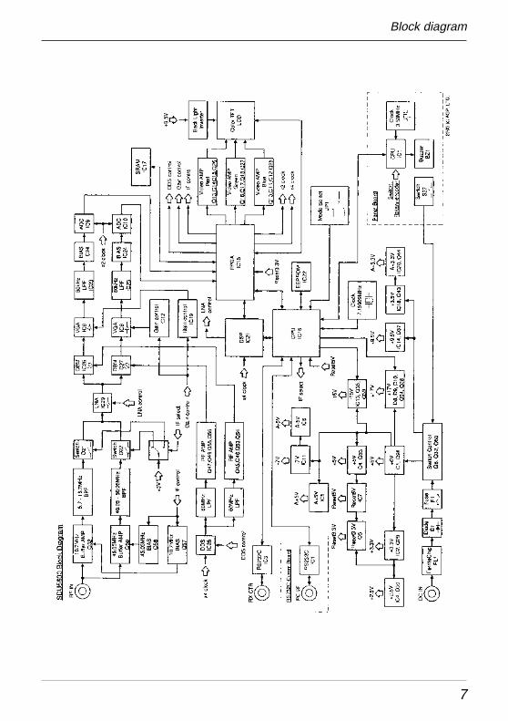
Circuit description
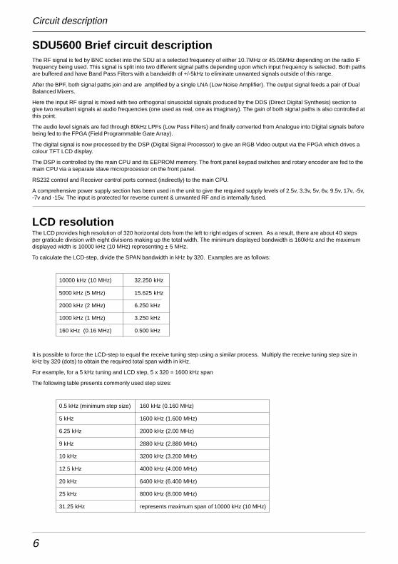
SDU5600 Brief circuit descriptionThe RF signal is fed by BNC socket into the SDU at a selected frequency of either 10.7MHz or 45.05MHz depending on the radio IFfrequency being used. This signal is split into two different signal paths depending upon which input frequency is selected. Both pathsare buffered and have Band Pass Filters with a bandwidth of +/-5kHz to eliminate unwanted signals outside of this range.
After the BPF, both signal paths join and are amplified by a single LNA (Low Noise Amplifier). The output signal feeds a pair of DualBalanced Mixers.
Here the input RF signal is mixed with two orthogonal sinusoidal signals produced by the DDS (Direct Digital Synthesis) section togive two resultant signals at audio frequencies (one used as real, one as imaginary). The gain of both signal paths is also controlled atthis point.
The audio level signals are fed through 80kHz LPFs (Low Pass Filters) and finally converted from Analogue into Digital signals beforebeing fed to the FPGA (Field Programmable Gate Array).
The digital signal is now processed by the DSP (Digital Signal Processor) to give an RGB Video output via the FPGA which drives acolour TFT LCD display.
The DSP is controlled by the main CPU and its EEPROM memory. The front panel keypad switches and rotary encoder are fed to themain CPU via a separate slave microprocessor on the front panel.
RS232 control and Receiver control ports connect (indirectly) to the main CPU.
A comprehensive power supply section has been used in the unit to give the required supply levels of 2.5v, 3.3v, 5v, 6v, 9.5v, 17v, -5v,-7v and -15v. The input is protected for reverse current & unwanted RF and is internally fused.
LCD resolutionThe LCD provides high resolution of 320 horizontal dots from the left to right edges of screen. As a result, there are about 40 stepsper graticule division with eight divisions making up the total width. The minimum displayed bandwidth is 160kHz and the maximumdisplayed width is 10000 kHz (10 MHz) representing ± 5 MHz.
To calculate the LCD-step, divide the SPAN bandwidth in kHz by 320. Examples are as follows:
10000 kHz (10 MHz) 32.250 kHz
5000 kHz (5 MHz) 15.625 kHz
2000 kHz (2 MHz) 6.250 kHz
1000 kHz (1 MHz) 3.250 kHz
160 kHz (0.16 MHz) 0.500 kHz
It is possible to force the LCD-step to equal the receive tuning step using a similar process. Multiply the receive tuning step size inkHz by 320 (dots) to obtain the required total span width in kHz.
For example, for a 5 kHz tuning and LCD step, 5 x 320 = 1600 kHz span
The following table presents commonly used step sizes:
0.5 kHz (minimum step size) 160 kHz (0.160 MHz)
5 kHz 1600 kHz (1.600 MHz)
6.25 kHz 2000 kHz (2.00 MHz)
9 kHz 2880 kHz (2.880 MHz)
10 kHz 3200 kHz (3.200 MHz)
12.5 kHz 4000 kHz (4.000 MHz)
20 kHz 6400 kHz (6.400 MHz)
25 kHz 8000 kHz (8.000 MHz)
31.25 kHz represents maximum span of 10000 kHz (10 MHz)
7
Block diagram
8
IntroductionThank you for purchasing the SDU5600 FFT spectrum display unit. AOR was thefirst company in the world to market a colour spectrum display unit (SDU5000) forprofessionals and the top-end of hobbyist listeners. The SDU5500 followed addingsophistication and the SDU5600 is truly a successor incorporating a high resolution5 inch (127mm) colour TFT display featuring FFT signal analysis and built-in waterfalldisplay backed by the latest microprocessor technology to ensure high versatility andreliability. To get the best possible results, we recommended that you read this manualto fully familiarise yourself with the SDU5600.
Major features
The SDU5600 has been designed to be a highly effective spectrum monitor unit whichis capable of digitally processing the IF frequency taken from a communicationsreceiver through the use of FFT for professional quality spectrum analysis. The 5 inchTFT colour LCD screen is used to achieve the finest possible resolution.
The SDU5600 has been primarily designed to complement to the AOR AR5000 seriesof receivers in terms of operational features and cosmetic design. Also other types ofreceiver such as the AOR AR-ONE, AR3000A and AR8600MK2 and ICOM ICR8500 +ICR7100 can be used (modification and additional hardware required).
A wide variety of monitoring modes are available with the convenience of operators inmind which include Step Resolution Mode for general monitoring or Channel ScopeMode for monitoring the channelised signals. It also incorporates a Waterfall facility(as commercial grade spectrum analysers do), to display the changing conditions ofsignal spectrum with varying colours in a form of waterfall.
Following the success of its predecessors, SDU5000 and SDU5500, the newSDU5600 provides the same AV, Peak Hold and Peak value readings which aredownloadable to the PC via a communications port. The SDU5600 can be remotecontrolled through the use of the communications port to further expand the range ofapplications for spectrum monitoring.
Supplied accessories
1 x SDU5600 main unit
1 x BNC RF patch lead for IF connection
1 x DB9 patch lead for serial communications - male to male
1 x Handbook
1 x AC power supply
Introduction & preparation
9
1 Controls and DescriptionsControl and display of the SDU5600 is via the front panel with the rear panelproviding connections for the companion receiver, power and computer.
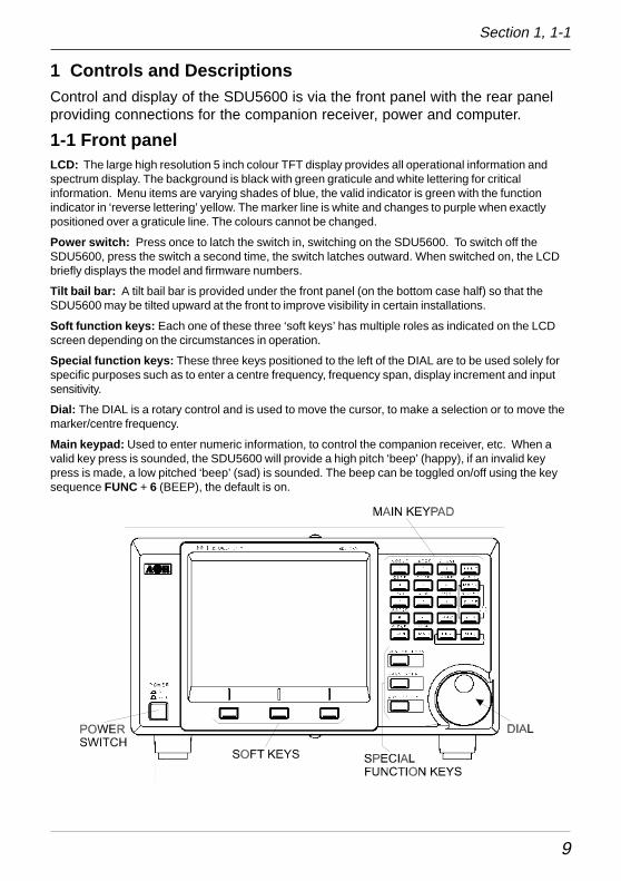
1-1 Front panelLCD: The large high resolution 5 inch colour TFT display provides all operational information andspectrum display. The background is black with green graticule and white lettering for criticalinformation. Menu items are varying shades of blue, the valid indicator is green with the functionindicator in ‘reverse lettering’ yellow. The marker line is white and changes to purple when exactlypositioned over a graticule line. The colours cannot be changed.
Power switch: Press once to latch the switch in, switching on the SDU5600. To switch off theSDU5600, press the switch a second time, the switch latches outward. When switched on, the LCDbriefly displays the model and firmware numbers.
Tilt bail bar: A tilt bail bar is provided under the front panel (on the bottom case half) so that theSDU5600 may be tilted upward at the front to improve visibility in certain installations.
Soft function keys: Each one of these three ‘soft keys’ has multiple roles as indicated on the LCDscreen depending on the circumstances in operation.
Special function keys: These three keys positioned to the left of the DIAL are to be used solely forspecific purposes such as to enter a centre frequency, frequency span, display increment and inputsensitivity.
Dial: The DIAL is a rotary control and is used to move the cursor, to make a selection or to move themarker/centre frequency.
Main keypad: Used to enter numeric information, to control the companion receiver, etc. When avalid key press is sounded, the SDU5600 will provide a high pitch ‘beep’ (happy), if an invalid keypress is made, a low pitched ‘beep’ (sad) is sounded. The beep can be toggled on/off using the keysequence FUNC + 6 (BEEP), the default is on.
Section 1, 1-1
10
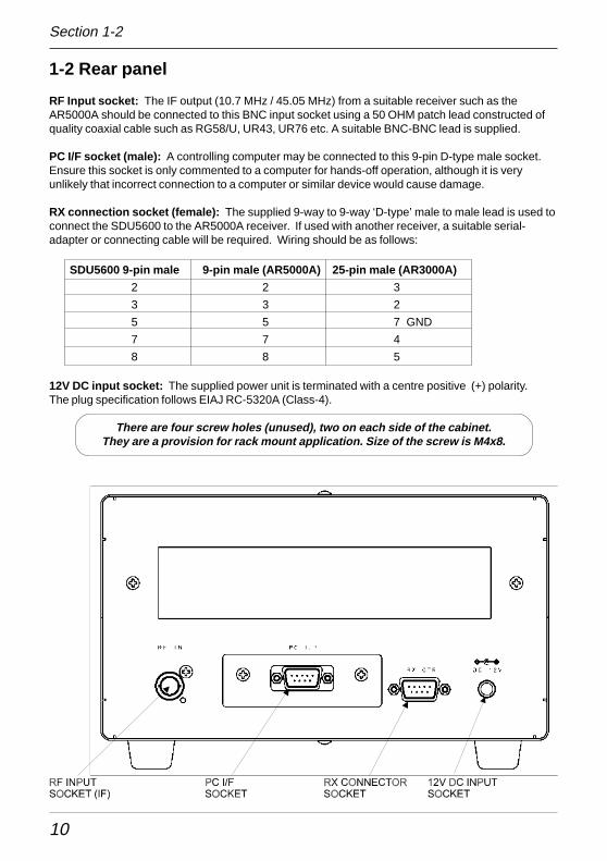
1-2 Rear panel
RF Input socket: The IF output (10.7 MHz / 45.05 MHz) from a suitable receiver such as theAR5000A should be connected to this BNC input socket using a 50 OHM patch lead constructed ofquality coaxial cable such as RG58/U, UR43, UR76 etc. A suitable BNC-BNC lead is supplied.
PC I/F socket (male): A controlling computer may be connected to this 9-pin D-type male socket.Ensure this socket is only commented to a computer for hands-off operation, although it is veryunlikely that incorrect connection to a computer or similar device would cause damage.
RX connection socket (female): The supplied 9-way to 9-way ‘D-type’ male to male lead is used toconnect the SDU5600 to the AR5000A receiver. If used with another receiver, a suitable serial-adapter or connecting cable will be required. Wiring should be as follows:
SDU5600 9-pin male 9-pin male (AR5000A) 25-pin male (AR3000A)
2 2 3
3 3 2
5 5 7 GND
7 7 4
8 8 5
12V DC input socket: The supplied power unit is terminated with a centre positive (+) polarity.The plug specification follows EIAJ RC-5320A (Class-4).
There are four screw holes (unused), two on each side of the cabinet.They are a provision for rack mount application. Size of the screw is M4x8.
Section 1-2
11
2 Connection2-1 Connection with the power supply
Where possible, use the supplied AC/DC power unit. Make sure the main switch of the SDU5600 isin the OFF position before connecting the power supply.
2-2 Connection with the receiver
This hand book is compiled mainly referring to the AR5000A series receiver as the principalcompanion receiver. Any reference to other types of receiver will be made separately when andwhere necessary.
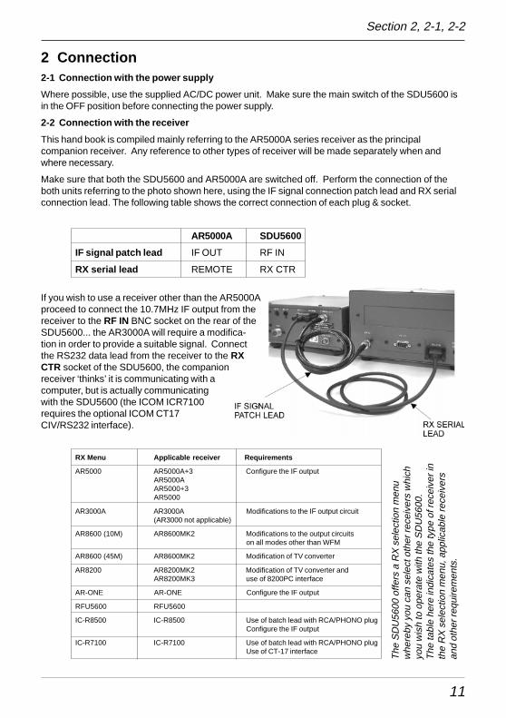
Make sure that both the SDU5600 and AR5000A are switched off. Perform the connection of theboth units referring to the photo shown here, using the IF signal connection patch lead and RX serialconnection lead. The following table shows the correct connection of each plug & socket.
AR5000A SDU5600
IF signal patch lead IF OUT RF IN
RX serial lead REMOTE RX CTR
If you wish to use a receiver other than the AR5000Aproceed to connect the 10.7MHz IF output from thereceiver to the RF IN BNC socket on the rear of theSDU5600... the AR3000A will require a modifica-tion in order to provide a suitable signal. Connectthe RS232 data lead from the receiver to the RXCTR socket of the SDU5600, the companionreceiver ‘thinks’ it is communicating with acomputer, but is actually communicatingwith the SDU5600 (the ICOM ICR7100requires the optional ICOM CT17CIV/RS232 interface).
RX Menu Applicable receiver Requirements
AR5000 AR5000A+3 Configure the IF outputAR5000AAR5000+3AR5000
AR3000A AR3000A Modifications to the IF output circuit(AR3000 not applicable)
AR8600 (10M) AR8600MK2 Modifications to the output circuitson all modes other than WFM
AR8600 (45M) AR8600MK2 Modification of TV converter
AR8200 AR8200MK2 Modification of TV converter andAR8200MK3 use of 8200PC interface
AR-ONE AR-ONE Configure the IF output
RFU5600 RFU5600
IC-R8500 IC-R8500 Use of batch lead with RCA/PHONO plugConfigure the IF output
IC-R7100 IC-R7100 Use of batch lead with RCA/PHONO plugUse of CT-17 interface
Section 2, 2-1, 2-2
The
SD
U56
00 o
ffers
a R
X s
elec
tion
men
uw
here
by y
ou c
an s
elec
t oth
er re
ceiv
ers
whi
chyo
u w
ish
to o
pera
te w
ith th
e S
DU
5600
.T
he ta
ble
here
indi
cate
s th
e ty
pe o
f rec
eive
r in
the
RX
sel
ectio
n m
enu,
app
licab
le re
ceiv
ers
and
othe
r req
uire
men
ts.
12
3 Preparations3-1 Configuration of the receiver
The SDU5600 is primarily designed to operate with the receiver at 9600bps. The companionreceiver’s baud rate has to be configured to the same rate. Some type of receivers may requireadditional modifications or interface, etc, which are explained as follows:-
AR5000 series: Configure the selection of external IF output and baud rate as per the followingtable (refer to pages 29 & 30 sections 6-18 & 6-19 of AR5000 English language operating manual):
External IF output Select [EXT-IF 1]
RS232C Select 9600bps
After the configurations have been completed placethe receiver in VFO mode.
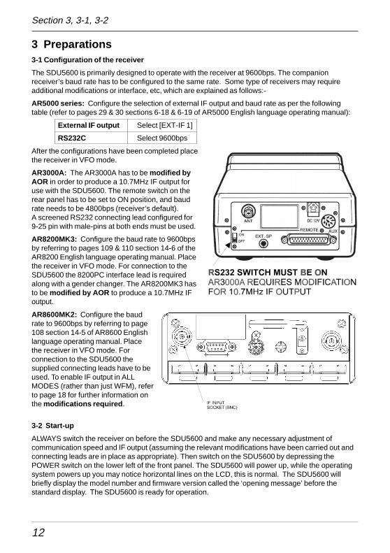
AR3000A: The AR3000A has to be modified byAOR in order to produce a 10.7MHz IF output foruse with the SDU5600. The remote switch on therear panel has to be set to ON position, and baudrate needs to be 4800bps (receiver’s default).A screened RS232 connecting lead configured for9-25 pin with male-pins at both ends must be used.
AR8200MK3: Configure the baud rate to 9600bpsby referring to pages 109 & 110 section 14-6 of theAR8200 English language operating manual. Placethe receiver in VFO mode. For connection to theSDU5600 the 8200PC interface lead is requiredalong with a gender changer. The AR8200MK3 hasto be modified by AOR to produce a 10.7MHz IFoutput.
AR8600MK2: Configure the baudrate to 9600bps by referring to page108 section 14-5 of AR8600 Englishlanguage operating manual. Placethe receiver in VFO mode. Forconnection to the SDU5600 thesupplied connecting leads have to beused. To enable IF output in ALLMODES (rather than just WFM), referto page 18 for further information onthe modifications required .
3-2 Start-up
ALWAYS switch the receiver on before the SDU5600 and make any necessary adjustment ofcommunication speed and IF output (assuming the relevant modifications have been carried out andconnecting leads are in place as appropriate). Then switch on the SDU5600 by depressing thePOWER switch on the lower left of the front panel. The SDU5600 will power up, while the operatingsystem powers up you may notice horizontal lines on the LCD, this is normal. The SDU5600 willbriefly display the model number and firmware version called the ‘opening message’ before thestandard display. The SDU5600 is ready for operation.
Section 3, 3-1, 3-2
13
4 BasicsThis section describes the front panel controls, detail of LCD display and introduces the method ofoperation employed by the SDU5600 prior to further configurations and monitoring operations. It isadvisable that you read this section carefully before proceeding to explore the full capability of theSDU5600.
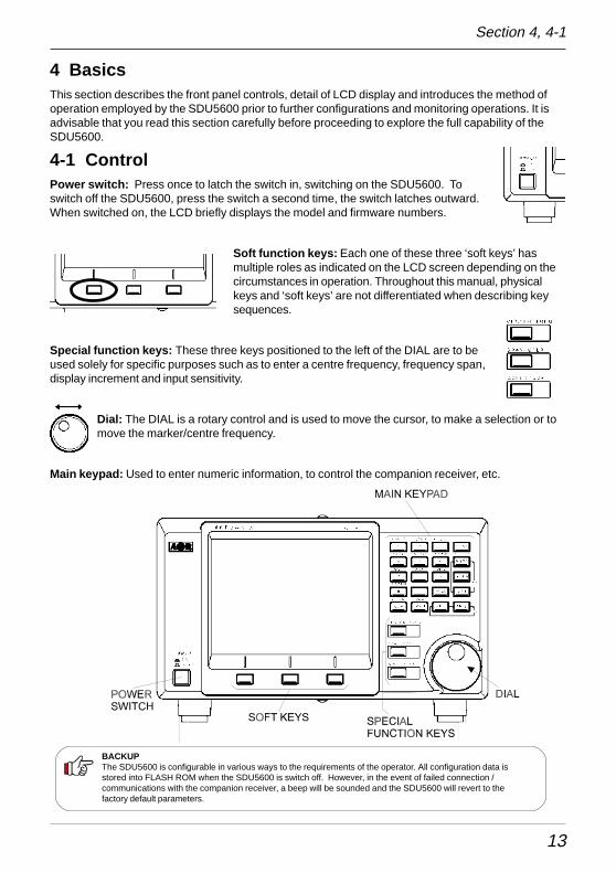
4-1 ControlPower switch: Press once to latch the switch in, switching on the SDU5600. Toswitch off the SDU5600, press the switch a second time, the switch latches outward.When switched on, the LCD briefly displays the model and firmware numbers.
Soft function keys: Each one of these three ‘soft keys’ hasmultiple roles as indicated on the LCD screen depending on thecircumstances in operation. Throughout this manual, physicalkeys and ‘soft keys’ are not differentiated when describing keysequences.
Special function keys: These three keys positioned to the left of the DIAL are to beused solely for specific purposes such as to enter a centre frequency, frequency span,display increment and input sensitivity.
Dial: The DIAL is a rotary control and is used to move the cursor, to make a selection or tomove the marker/centre frequency.
Main keypad: Used to enter numeric information, to control the companion receiver, etc.
Section 4, 4-1
BACKUPThe SDU5600 is configurable in various ways to the requirements of the operator. All configuration data isstored into FLASH ROM when the SDU5600 is switch off. However, in the event of failed connection /communications with the companion receiver, a beep will be sounded and the SDU5600 will revert to thefactory default parameters.
14
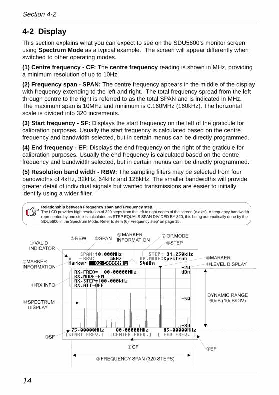
4-2 DisplayThis section explains what you can expect to see on the SDU5600’s monitor screenusing Spectrum Mode as a typical example. The screen will appear differently whenswitched to other operating modes.
(1) Centre frequency - CF: The centre frequency reading is shown in MHz, providinga minimum resolution of up to 10Hz.
(2) Frequency span - SPAN: The centre frequency appears in the middle of the displaywith frequency extending to the left and right. The total frequency spread from the leftthrough centre to the right is referred to as the total SPAN and is indicated in MHz.The maximum span is 10MHz and minimum is 0.160MHz (160kHz). The horizontalscale is divided into 320 increments.
(3) Start frequency - SF: Displays the start frequency on the left of the graticule forcalibration purposes. Usually the start frequency is calculated based on the centrefrequency and bandwidth selected, but in certain menus can be directly programmed.
(4) End frequency - EF: Displays the end frequency on the right of the graticule forcalibration purposes. Usually the end frequency is calculated based on the centrefrequency and bandwidth selected, but in certain menus can be directly programmed.
(5) Resolution band width - RBW: The sampling filters may be selected from fourbandwidths of 4kHz, 32kHz, 64kHz and 128kHz. The smaller bandwidths will providegreater detail of individual signals but wanted transmissions are easier to initiallyidentify using a wider filter.
Section 4-2
Relationship between Frequency span and Frequency stepThe LCD provides high resolution of 320 steps from the left to right edges of the screen (x-axis). A frequency bandwidthrepresented by one step is calculated as STEP EQUALS SPAN DIVIDED BY 320, this being automatically done by theSDU5600 in the Spectrum Mode. Refer to item (6) ‘Frequency step’ on page 15.
15
(6) Step frequency - STEP: This value is displayed in kHz and indicates how wide one steprepresents out of the 320 steps across the X-axis. The example of page 14 shows 31.250kHz as onestep which is obtained by taking the SPAN of 10MHz and dividing it by 320, the result is 31.250kHz -since the X-axis is 10MHz wide in this example. In the Step resolution mode, it is possible to specifythe frequency bandwidth to be ‘one step’ rather than an often seemingly arbitrary value.
(7) Operation mode - OP.MODE: This legend indicates which one of three operating modes isselected, there are three possibilities:
Spectrum Spectrum analyser modeStepReso Step resolution modeChannel Channel scope mode
(8) Marker + (9) Marker information: The marker (8) is a vertical line drawn on the LCD which canbe moved across the horizontal axis. The marker is capable of providing the instantaneous reading ofinformation where the marker is placed such as (9) frequency or signal strength of marker location.In the marker menu, in addition to the instantaneous reading of marker information, the peaksearch facility is provided. Any signals which are out of scale cannot be read. It is necessary toadjust the gain for input signal level, the displayed signal appears vertically while the calibration linesof the graticule are represented horizontally.
(10) Valid indicator: This indicates which method of data input is valid. When a DOT � is shown, themain dial is operational whereas when SQUARE ¢ is displayed, entry through the keypad isoperational.
(11) Receiver information: This section of the LCD provides various operating conditions of thecompanion receiver such as receiving frequency, modulation mode, tuning step and ATT on/off.The information can be toggle on and off via the key sequence FUNC 5 (DISP)
(12) Signal indicator + (13) Level indicator: The X-axis (horizontal line) indicates frequency, andY-axis (vertical line) indicates signal strength, so the frequency spectrum of the received signalis indicated on the screen.
The Y-axis (vertical line) is split into six segments with each segment representing a 10dB. The levelindicator reads the input sensitivity which is shown along the Y-axis and the level is adjustable in fourlevels by altering the built-in amplifier (AMPLITUDE). The X-axis is split into eight segmentsindicating the frequency span (bandwidth) in use. The marker is designed to move across the onesegment by ONE full rotation of the main dial. To move the marker from one edge to another requiresEIGHT rotations of the main dial.
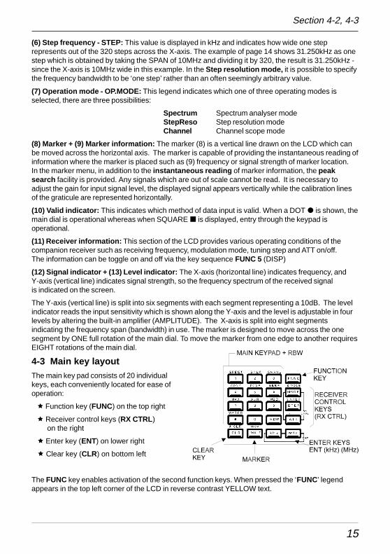
4-3 Main key layoutThe main key pad consists of 20 individualkeys, each conveniently located for ease ofoperation:
ê Function key (FUNC) on the top right
ê Receiver control keys (RX CTRL) on the right
ê Enter key (ENT) on lower right
ê Clear key (CLR) on bottom left
The FUNC key enables activation of the second function keys. When pressed the ‘FUNC’ legendappears in the top left corner of the LCD in reverse contrast YELLOW text.
Section 4-2, 4-3
16
4-4 Clear (CLR) keyThe clear key (CLR) acts as back-space key to cancel each proceeding keyentry of numeric information (1 to 0, decimal-point ) during entry of the start/end frequency, entry of input sensitivity / trigger level or the marker andnumeration in the calculation mode. Pressing the clear key with no proceedingkey entry will abort the sequence. Pressing A.CLR (FUNC + CLR) will clear allproceeding numeric entries and end the sequence.
Pressing the clear key (CLR) repeatedly in the calculation mode, marker mode(except the instantaneous reading) and waterfall display mode will eventuallyreturn operation to the default mode, see below.
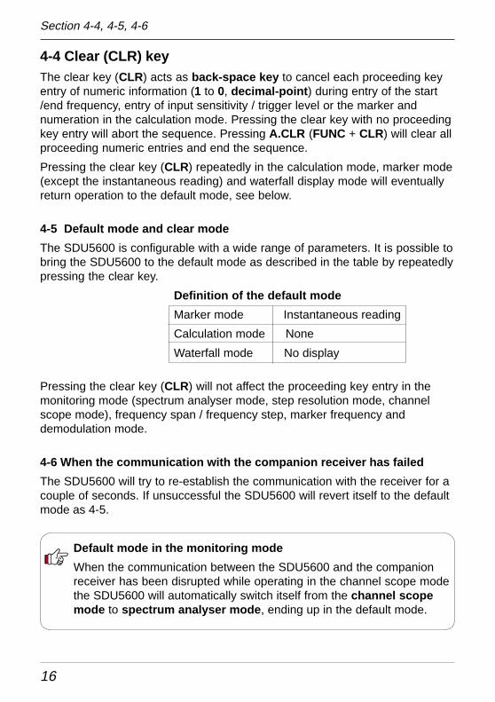
4-5 Default mode and clear mode
The SDU5600 is configurable with a wide range of parameters. It is possible tobring the SDU5600 to the default mode as described in the table by repeatedlypressing the clear key.
Definition of the default mode
Marker mode Instantaneous reading
Calculation mode None
Waterfall mode No display
Pressing the clear key (CLR) will not affect the proceeding key entry in themonitoring mode (spectrum analyser mode, step resolution mode, channelscope mode), frequency span / frequency step, marker frequency anddemodulation mode.
4-6 When the communication with the companion receiver has failed
The SDU5600 will try to re-establish the communication with the receiver for acouple of seconds. If unsuccessful the SDU5600 will revert itself to the defaultmode as 4-5.
Default mode in the monitoring mode
When the communication between the SDU5600 and the companionreceiver has been disrupted while operating in the channel scope modethe SDU5600 will automatically switch itself from the channel scopemode to spectrum analyser mode , ending up in the default mode.
Section 4-4, 4-5, 4-6
17
5. Configuration of the SDU5600The SDU5600 is designed to configure a wide range of parameters for ease of operation.
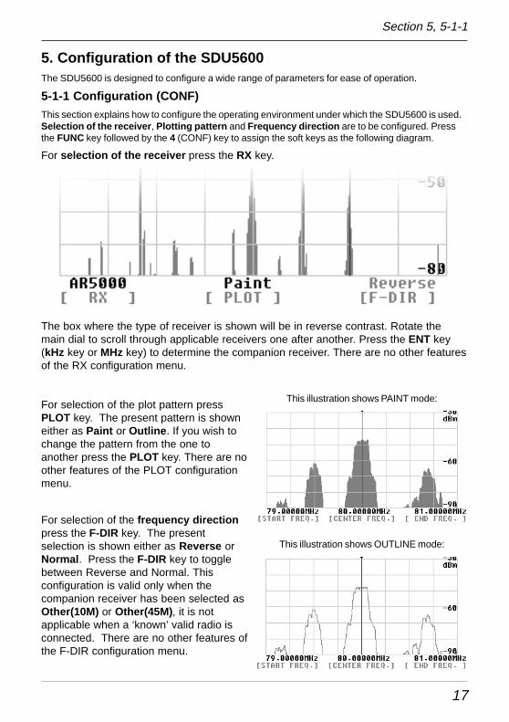
5-1-1 Configuration (CONF)This section explains how to configure the operating environment under which the SDU5600 is used.Selection of the receiver , Plotting pattern and Frequency direction are to be configured. Pressthe FUNC key followed by the 4 (CONF) key to assign the soft keys as the following diagram.
For selection of the receiver press the RX key.
The box where the type of receiver is shown will be in reverse contrast. Rotate themain dial to scroll through applicable receivers one after another. Press the ENT key(kHz key or MHz key) to determine the companion receiver. There are no other featuresof the RX configuration menu.
For selection of the plot pattern pressPLOT key. The present pattern is showneither as Paint or Outline . If you wish tochange the pattern from the one toanother press the PLOT key. There are noother features of the PLOT configurationmenu.
For selection of the frequency directionpress the F-DIR key. The presentselection is shown either as Reverse orNormal . Press the F-DIR key to togglebetween Reverse and Normal. Thisconfiguration is valid only when thecompanion receiver has been selected asOther(10M) or Other(45M) , it is notapplicable when a ‘known’ valid radio isconnected. There are no other features ofthe F-DIR configuration menu.
This illustration shows PAINT mode:
This illustration shows OUTLINE mode:
Section 5, 5-1-1
18
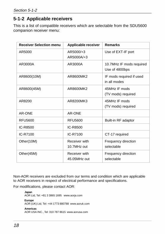
5-1-2 Applicable receiversThis is a list of compatible receivers which are selectable from the SDU5600companion receiver menu:
Receiver Selection menu Applicable receiver Remarks
AR5000 AR5000/+3 Use of EXT-IF port
AR5000A/+3
AR3000A AR3000A 10.7MHz IF mods required
Use of 4800bps
AR8600(10M) AR8600MK2 IF mods required if used
in all modes
AR8600(45M) AR8600MK2 45MHz IF mods
(TV mods) required
AR8200 AR8200MK3 45MHz IF mods
(TV mods) required
AR-ONE AR-ONE
RFU5600 RFU5600 Built-in RF adaptor
IC-R8500 IC-R8500
IC-R7100 IC-R7100 CT-17 required
Other(10M) Receiver with Frequency direction
10.7MHz out selectable
Other(45M) Receiver with Frequency direction
45.05MHz out selectable
Non-AOR receivers are excluded from our terms and condition which are applicableto AOR receivers in respect of electrical performance and specifications.
For modifications, please contact AOR:
JapanAOR Ltd, Tel: +81 3 3865 1695 www.aorja.com
EuropeAOR (UK) Ltd, Tel: +44 1773 880788 www.aoruk.com
AmericasAOR USA INC., Tel: 310 787 8615 www.aorusa.com
Section 5-1-2
19
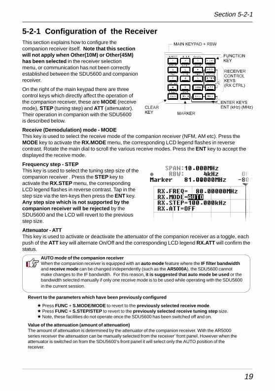
5-2-1 Configuration of the ReceiverThis section explains how to configure thecompanion receiver itself. Note that this sectionwill not apply when Other(10M) or Other(45M)has been selected in the receiver selectionmenu, or communication has not been correctlyestablished between the SDU5600 and companionreceiver.
On the right of the main keypad there are threecontrol keys which directly affect the operation ofthe companion receiver, these are MODE (receivemode), STEP (tuning step) and ATT (attenuator).Their operation in companion with the SDU5600is described below.
Receive (Demodulation) mode - MODEThis key is used to select the receive mode of the companion receiver (NFM, AM etc). Press theMODE key to activate the RX.MODE menu, the corresponding LCD legend flashes in reversecontrast. Rotate the main dial to scroll the various receive modes. Press the ENT key to accept thedisplayed the receive mode.
Frequency step - STEPThis key is used to select the tuning step size of thecompanion receiver . Press the STEP key toactivate the RX.STEP menu, the correspondingLCD legend flashes in reverse contrast. Tap in thestep size via the ten-keys then press the ENT key.Any step size which is not supported by thecompanion receiver will be rejected by theSDU5600 and the LCD will revert to the previousstep size.
Attenuator - ATTThis key is used to activate or deactivate the attenuator of the companion receiver as a toggle, eachpush of the ATT key will alternate On/Off and the corresponding LCD legend RX.ATT will confirm thestatus.
AUTO mode of the companion receiverWhen the companion receiver is equipped with an auto mode feature where the IF filter bandwidthand receive mode can be changed independently (such as the AR5000A), the SDU5600 cannotmake changes to the IF bandwidth. For this reason, it is suggested that auto mode be used or thebandwidth selected manually if only one receive mode is to be used while operating with the SDU5600in the current session.
Section 5-2-1
Revert to the parameters which have been previously configured
ê Press FUNC + S.MODE/MODE to revert to the previously selected receive mode .ê Press FUNC + S.STEP/STEP to revert to the previously selected receive tuning step size.ê Note, these facilities do not operate once the SDU5600 has been switched off and on.
Value of the attenuation (amount of attenuation)The amount of attenuation is determined by the attenuator of the companion receiver. With the AR5000series receiver the attenuation can be manually selected from the receiver’ front panel. However when theattenuator is switched on from the SDU5600’s front panel it will select only the AUTO position of thereceiver.
20
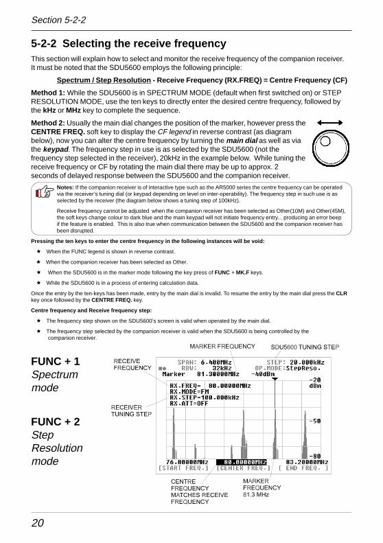
5-2-2 Selecting the receive frequencyThis section will explain how to select and monitor the receive frequency of the companion receiver.It must be noted that the SDU5600 employs the following principle:
Spectrum / Step Resolution - Receive Frequency (RX.FREQ) = Centre Frequency (CF)
Method 1: While the SDU5600 is in SPECTRUM MODE (default when first switched on) or STEPRESOLUTION MODE, use the ten keys to directly enter the desired centre frequency, followed bythe kHz or MHz key to complete the sequence.
Method 2: Usually the main dial changes the position of the marker, however press theCENTRE FREQ. soft key to display the CF legend in reverse contrast (as diagrambelow), now you can alter the centre frequency by turning the main dial as well as viathe keypad . The frequency step in use is as selected by the SDU5600 (not thefrequency step selected in the receiver), 20kHz in the example below. While tuning thereceive frequency or CF by rotating the main dial there may be up to approx. 2seconds of delayed response between the SDU5600 and the companion receiver.
Notes: If the companion receiver is of interactive type such as the AR5000 series the centre frequency can be operatedvia the receiver’s tuning dial (or keypad depending on level on inter-operability). The frequency step in such use is asselected by the receiver (the diagram below shows a tuning step of 100kHz).
Receive frequency cannot be adjusted when the companion receiver has been selected as Other(10M) and Other(45M),the soft keys change colour to dark blue and the main keypad will not initiate frequency entry... producing an error beepif the feature is enabled. This is also true when communication between the SDU5600 and the companion receiver hasbeen disrupted.
Pressing the ten keys to enter the centre frequency in the following instances will be void:
ê When the FUNC legend is shown in reverse contrast.
ê When the companion receiver has been selected as Other.
ê When the SDU5600 is in the marker mode following the key press of FUNC + MK.F keys.
ê While the SDU5600 is in a process of entering calculation data.
Once the entry by the ten-keys has been made, entry by the main dial is invalid. To resume the entry by the main dial press the CLRkey once followed by the CENTRE FREQ. key.
Centre frequency and Receive frequency step:
ê The frequency step shown on the SDU5600’s screen is valid when operated by the main dial.
ê The frequency step selected by the companion receiver is valid when the SDU5600 is being controlled by the companion receiver.
FUNC + 1Spectrummode
FUNC + 2StepResolutionmode
Section 5-2-2
21
Channel scope mode
The previous page explains the receive frequency operation in the spectrum analyser mode and stepresolution mode. The channel scope mode differs since it does not use the centre frequency (CF),instead the receive frequency equals the marker position:
Channel Scope Mode - Receive Frequency = Receive Marker position
In addition, by use of the marker receive key MK.F you can track and select any active receivefrequency for monitoring within the frequency band presently shown on the screen.
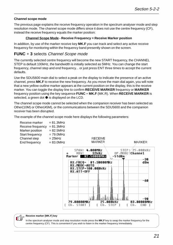
FUNC + 3 selects Channel Scope modeThe currently selected centre frequency will become the new START frequency, the CHANNELSTEP is default 100kHz, the bandwidth is initially selected as 5MHz. You can change the startfrequency, channel step and end frequency... or just press ENT three times to accept the currentdefaults.
Use the SDU5600 main dial to select a peak on the display to indicate the presence of an activechannel, press MK.F to receive the new frequency. As you move the main dial again, you will notethat a new yellow-outline marker appears at the current position on the display, this is the receivemarker. You can toggle the display line to confirm RECEIVE MARKER frequency or MARKERfrequency position using the key sequence FUNC + MK.F (MK.R). When RECEIVE MARKER isselected, a green dot � is displayed on the LCD.
The channel scope mode cannot be selected when the companion receiver has been selected asOther(10M) or Other(45M), or the communications between the SDU5600 and the companionreceiver has been disrupted.
The example of the channel scope mode here displays the following parameters:
Receive marker = 81.3MHzReceive frequency = 81.3MHzMarker position = 82.5MHzStart frequency = 79.0MHzChannel step = 25kHzEnd frequency = 83.0MHz
Receive marker [MK.F] key
In the spectrum analyser mode and step resolution mode press the MK.F key to swap the marker frequency for thecentre frequency (CF). This is convenient if you wish to listen in the marker frequency immediately.
Section 5-2-2
22
5-3 Setup of the monitoring modeThe SDU5600 is designed to provide 3 different monitoring modes such as the spectrum analysermode, step resolution mode and channel scope mode. Choosing the most appropriate monitoringmode for your specific requirements is important to maximise performance and efficiency of theSDU5600.
Method of selecting each monitoring mode:
Spectrum analyser mode Press FUNC + 1 (SPECT)
Step resolution mode Press FUNC + 2 (STEP)
Channel scope mode Press FUNC + 3 (CHANL)
The 1, 2 and 3 keys are allocated with the ‘secondfunction’. The selected mode is displayed on the secondline from the top-right side of the LCD as OP.MODEEach mode has unique features.
Spectrum analyser mode (SPECT)This is most suited for general listening and to hunt for non specific signals or noise,by sweeping across the defined range of spectrum (up to a bandwidth of 10MHz).
Step resolution mode (StepReso)This is most suited to monitor specific signals across a known relatively wide definedband where signals are allocated with a certain stepping size, for example VHFairband. The horizontal x-axis of the LCD has a resolution of 320 dots, each dotrepresents one step, so there are a total of 320 steps.
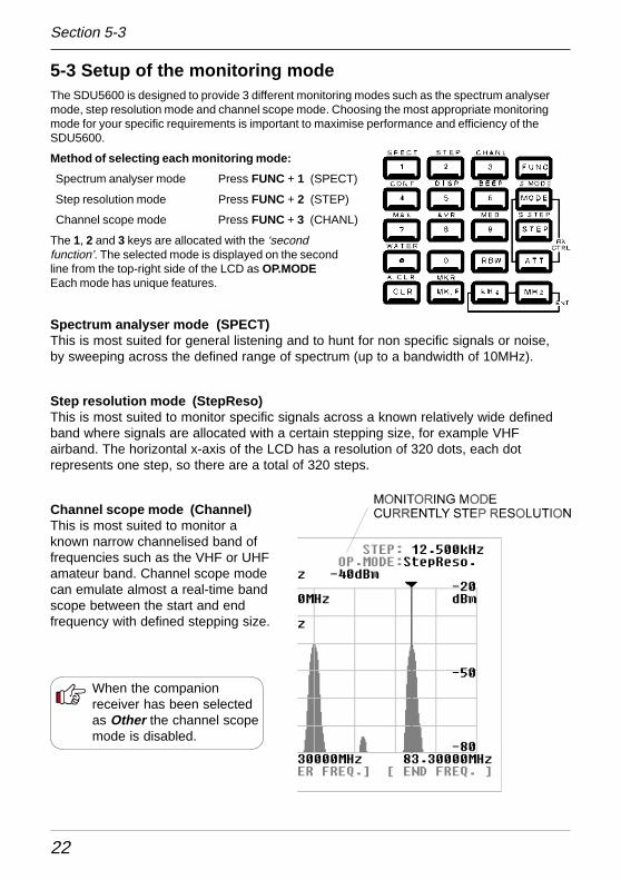
Channel scope mode (Channel)This is most suited to monitor aknown narrow channelised band offrequencies such as the VHF or UHFamateur band. Channel scope modecan emulate almost a real-time bandscope between the start and endfrequency with defined stepping size.
When the companionreceiver has been selectedas Other the channel scopemode is disabled.
Section 5-3
23
5-4 Basic setup for each monitoring modeThis section will explain how each monitoring mode has to be set up.
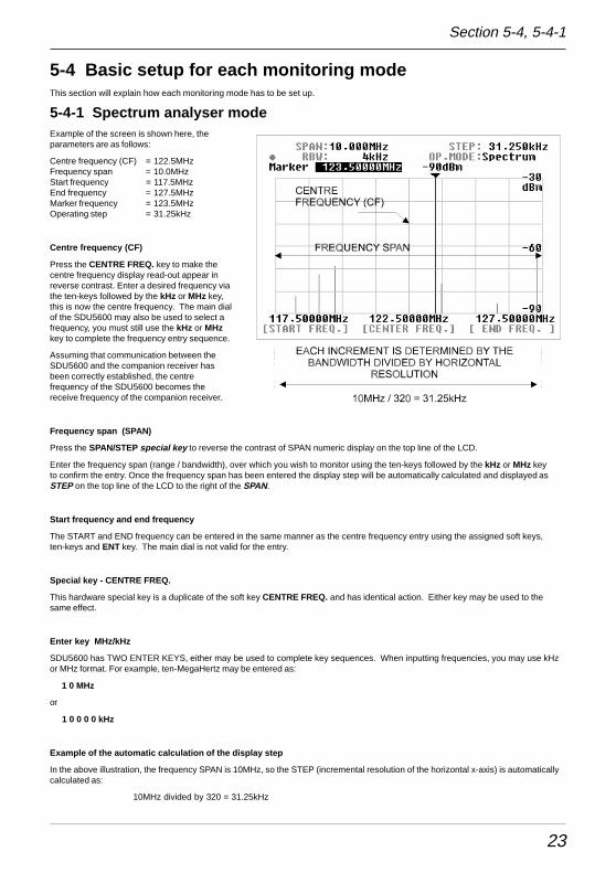
5-4-1 Spectrum analyser modeExample of the screen is shown here, theparameters are as follows:
Centre frequency (CF) = 122.5MHzFrequency span = 10.0MHzStart frequency = 117.5MHzEnd frequency = 127.5MHzMarker frequency = 123.5MHzOperating step = 31.25kHz
Centre frequency (CF)
Press the CENTRE FREQ. key to make thecentre frequency display read-out appear inreverse contrast. Enter a desired frequency viathe ten-keys followed by the kHz or MHz key,this is now the centre frequency. The main dialof the SDU5600 may also be used to select afrequency, you must still use the kHz or MHzkey to complete the frequency entry sequence.
Assuming that communication between theSDU5600 and the companion receiver hasbeen correctly established, the centrefrequency of the SDU5600 becomes thereceive frequency of the companion receiver.
Frequency span (SPAN)
Press the SPAN/STEP special key to reverse the contrast of SPAN numeric display on the top line of the LCD.
Enter the frequency span (range / bandwidth), over which you wish to monitor using the ten-keys followed by the kHz or MHz keyto confirm the entry. Once the frequency span has been entered the display step will be automatically calculated and displayed asSTEP on the top line of the LCD to the right of the SPAN.
Start frequency and end frequency
The START and END frequency can be entered in the same manner as the centre frequency entry using the assigned soft keys,ten-keys and ENT key. The main dial is not valid for the entry.
Special key - CENTRE FREQ.
This hardware special key is a duplicate of the soft key CENTRE FREQ. and has identical action. Either key may be used to thesame effect.
Enter key MHz/kHz
SDU5600 has TWO ENTER KEYS, either may be used to complete key sequences. When inputting frequencies, you may use kHzor MHz format. For example, ten-MegaHertz may be entered as:
1 0 MHz
or
1 0 0 0 0 kHz
Example of the automatic calculation of the display step
In the above illustration, the frequency SPAN is 10MHz, so the STEP (incremental resolution of the horizontal x-axis) is automaticallycalculated as:
10MHz divided by 320 = 31.25kHz
Section 5-4, 5-4-1
24
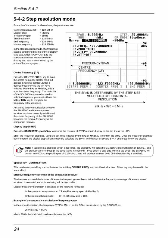
5-4-2 Step resolution modeExample of the screen is shown here, the parameters are:
Centre frequency (CF) = 122.5MHzDisplay step = 25kHz Frequency span = 8MHzStart frequency = 118.5MHzEnd frequency = 126.5MHzMarker frequency = 124.35MHz
In the step resolution mode, the frequencyspan is determined by the entry of displaystep size, which is OPPOSITE to thespectrum analyser mode where thedisplay step size is determined by theentry of frequency span.
Centre frequency (CF)
Press the CENTRE FREQ. key to makethe centre frequency display read-outappear in reverse contrast. Enter adesired frequency via the ten-keysfollowed by the kHz or MHz key, this isnow the centre frequency. The main dialof the SDU5600 may also be used toselect a frequency, you must still use thekHz or MHz key to complete thefrequency entry sequence.
Assuming that communication betweenthe SDU5600 and the companionreceiver has been correctly established,the centre frequency of the SDU5600becomes the receive frequency of thecompanion receiver.
Display step (STEP)
Press the SPAN/STEP special key to reverse the contrast of STEP numeric display on the top line of the LCD.
Enter the frequency step size, using the ten-keys followed by the kHz or MHz key to confirm the entry. Once the frequency step hasbeen entered, the display step will automatically calculate the SPAN and display STEP and SPAN on the top line of the display.
Note: If you select a step size which is too large, the SDU5600 will default to 31.250kHz step with span of 10MHz... andwill produce an error beep (if the beep facility is enabled). If you select a step size which is too small, the SDU5600 willdefault to 0.500kHz step with span of 0.160MHz... and will produce an error beep (if the beep facility is enabled).
Special key - CENTRE FREQ.
This hardware special key is a duplicate of the soft key CENTRE FREQ. and has identical action. Either key may be used to thesame effect.
Effective frequency coverage of the companion receiver
The frequency spread (both sides of the centre frequency) must be contained within the frequency coverage of the companionreceiver. If exceeded, correct monitoring will be impossible.
Display frequency bandwidth is obtained by the following formulae:-
In the spectrum analyser mode: CF +/- (Frequency span divided by 2)
In the step resolution mode: CF +/- (Display step x 160)
Example of the automatic calculation of frequency span
In the above illustration, the frequency STEP is 25kHz, so the SPAN is calculated by the SDU5600 as:
25kHz x 320 = 8MHz
where 320 is the horizontal x-axis resolution of the LCD.
.
Section 5-4-2
25
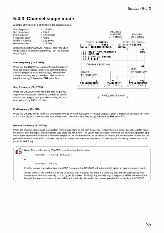
5-4-3 Channel scope modeExample of the screen is shown here, the parameters are:
Start frequency = 118.0MHzStep frequency = 25kHzEnd frequency = 122.00MHzFrequency span = 4MHzMarker frequency = 121.8MHzReceive marker = 119.7MHz
Unlike the spectrum analyser mode or step resolutionmode there is no centre frequency (CF) in the channelscope mode.
Start frequency (Ch.ST ART)
Press the Ch.START key to make the start frequencyread-out display appear in reverse contrast. Enter adesired frequency using the ten-keys, which is thelowest of the frequency spread you wish to monitor(start frequency), followed by ENT to confirm.
Step frequency (Ch. STEP)
Press the Ch.STEP key to make the step frequencydisplay red-out appear in reverse contrast. Enter thedesired step frequency of your choice using the ten-keys followed by ENT to confirm.
End frequency (Ch.END)
Press the Ch.END key to make the end frequency display read-out appear in reverse contrast. Enter a frequency, using the ten-keys,which is the highest of the frequency spread you wish to monitor (end frequency), followed by ENT to confirm.
Receive frequency (RX.FREQ)
When the channel scope mode is activated, monitoring begins on the start frequency. Rotate the main dial of the SDU5600 to movethe marker onto the signal of your interest, and press the MK.F key. The yellow receive marker moves to the nominated position andthe companion receiver monitors the wanted frequency. As the main dial of the SDU5600 is rotated, the white marker moves and theyellow receive marker is left in position to signify the current active receive frequency. To select a new frequency to monitor, simplypress the MK.F key.
Note: The end frequency (Ch.END) is confined by the formulae:
(CH.START) + [ (Ch.STEP) x 160 ]
or
(CH.START) + 5MHz
For this reason, if you do not enter an END frequency, the SDU5600 will automatically select an appropriate end point.
Invalid entry for the end frequency will be alerted with a beep (if the feature is enabled), and the closest possible validfrequency will be automatically chosen by the SDU5600. Similarly, any invalid entry of frequency will be alerted with thebeep (if the feature is enabled), and will be automatically adjusted to the nearest possible frequency by the SDU5600.
Section 5-4-3
26
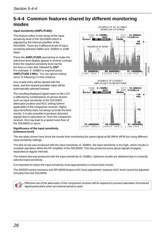
5-4-4 Common features shared by different monitoringmodesInput sensitivity (AMPLITUDE)
This feature refers to the setup of the inputsensitivity level of the SDU5600 which isadjusted by the internal amplifier of theSDU5600. There are 4 different levels of inputsensitivity between 0dBm and -30dBm in 10dBsteps.
Press the AMPLITUDE special key to make thereference level display appear in reverse contrast.Enter the required sensitivity level via theten-keys or main dial, followed by ENT.For example, If -20dBm is required pressAMPLITUDE 2 MHz. You can ignore trailingzeros ‘0’ following 2 in this instance.
Any invalid entry will be alerted with thebeep, and the nearest possible value will beautomatically selected instead.
The resulting displayed signal wave on the LCDis affected by combinations of various factorssuch as input sensitivity of the SDU5600,attenuator position and AGC setting (whereapplicable) of the companion receiver. Higherinput sensitivity does not always provide the bestresults. It is also possible to produce distortedsignals due to saturation to / from the companionreceiver, this may lead to a raised noise floor ofthe SDU5600 or spurs.
Significance of the input sensitivity(reference level)
The two plots shown here show the results from monitoring the same signal at 80.0MHz WFM but using differentinput sensitivity settings.
The plot on top was produced with the input sensitivity of -30dBm, the input sensitivity is too high, which results inunstable operation within the RF amplifier of the SDU5600. This has produced some ghost signals (images)separated at regular intervals.
The bottom plot was produced with the input sensitivity of -20dBm. Optimum results are obtained due to correctlyselected input sensitivity.
It is important to select the input sensitivity most appropriately to ensure best results.
The AR5000 series receivers and RFU5600 feature AGC level adjustment, however AGC level cannot be adjustedremotely from the SDU5600.
Effective use of the attenuator of the companion receiver will be required to prevent saturation of receivedsignal particularly when an external aerial is used.
Section 5-4-4
27
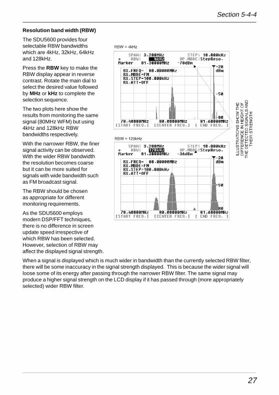
Resolution band width (RBW)
The SDU5600 provides fourselectable RBW bandwidthswhich are 4kHz, 32kHz, 64kHzand 128kHz.
Press the RBW key to make theRBW display appear in reversecontrast. Rotate the main dial toselect the desired value followedby MHz or kHz to complete theselection sequence.
The two plots here show theresults from monitoring the samesignal (80MHz WFM) but using4kHz and 128kHz RBWbandwidths respectively.
With the narrower RBW, the finersignal activity can be observed.With the wider RBW bandwidththe resolution becomes coarsebut it can be more suited forsignals with wide bandwidth suchas FM broadcast signal.
The RBW should be chosenas appropriate for differentmonitoring requirements.
As the SDU5600 employsmodern DSP/FFT techniques,there is no difference in screenupdate speed irrespective ofwhich RBW has been selected.However, selection of RBW mayaffect the displayed signal strength.
When a signal is displayed which is much wider in bandwidth than the currently selected RBW filter,there will be some inaccuracy in the signal strength displayed. This is because the wider signal willloose some of its energy after passing through the narrower RBW filter. The same signal mayproduce a higher signal strength on the LCD display if it has passed through (more appropriatelyselected) wider RBW filter.
Section 5-4-4
28
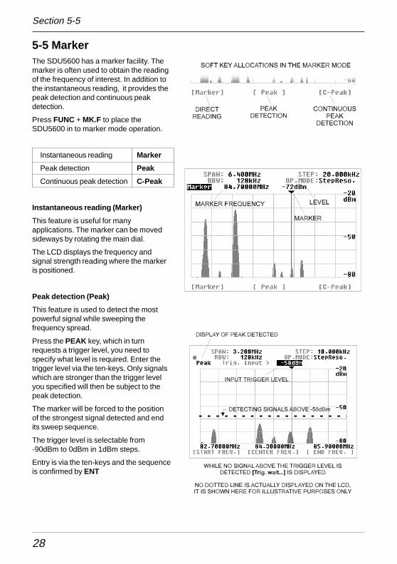
5-5 MarkerThe SDU5600 has a marker facility. Themarker is often used to obtain the readingof the frequency of interest. In addition tothe instantaneous reading, it provides thepeak detection and continuous peakdetection.
Press FUNC + MK.F to place theSDU5600 in to marker mode operation.
Instantaneous reading Marker
Peak detection Peak
Continuous peak detection C-Peak
Instantaneous reading (Marker)
This feature is useful for manyapplications. The marker can be movedsideways by rotating the main dial.
The LCD displays the frequency andsignal strength reading where the markeris positioned.
Peak detection (Peak)
This feature is used to detect the mostpowerful signal while sweeping thefrequency spread.
Press the PEAK key, which in turnrequests a trigger level, you need tospecify what level is required. Enter thetrigger level via the ten-keys. Only signalswhich are stronger than the trigger levelyou specified will then be subject to thepeak detection.
The marker will be forced to the positionof the strongest signal detected and endits sweep sequence.
The trigger level is selectable from-90dBm to 0dBm in 1dBm steps.
Entry is via the ten-keys and the sequenceis confirmed by ENT
Section 5-5
29
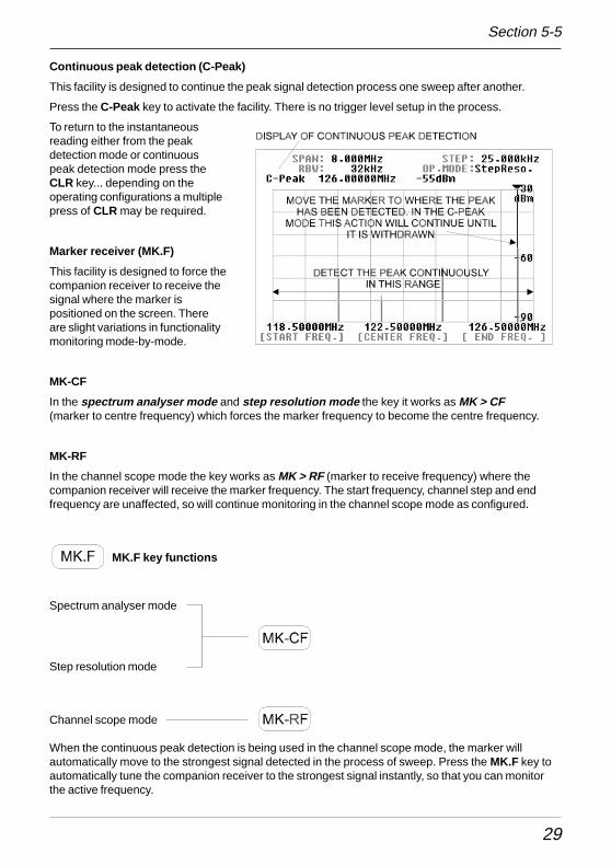
Continuous peak detection (C-Peak)
This facility is designed to continue the peak signal detection process one sweep after another.
Press the C-Peak key to activate the facility. There is no trigger level setup in the process.
To return to the instantaneousreading either from the peakdetection mode or continuouspeak detection mode press theCLR key... depending on theoperating configurations a multiplepress of CLR may be required.
Marker receiver (MK.F)
This facility is designed to force thecompanion receiver to receive thesignal where the marker ispositioned on the screen. Thereare slight variations in functionalitymonitoring mode-by-mode.
MK-CF
In the spectrum analyser mode and step resolution mode the key it works as MK > CF(marker to centre frequency) which forces the marker frequency to become the centre frequency.
MK-RF
In the channel scope mode the key works as MK > RF (marker to receive frequency) where thecompanion receiver will receive the marker frequency. The start frequency, channel step and endfrequency are unaffected, so will continue monitoring in the channel scope mode as configured.
MK.F key functions
Spectrum analyser mode
Step resolution mode
Channel scope mode
When the continuous peak detection is being used in the channel scope mode, the marker willautomatically move to the strongest signal detected in the process of sweep. Press the MK.F key toautomatically tune the companion receiver to the strongest signal instantly, so that you can monitorthe active frequency.
Section 5-5
30
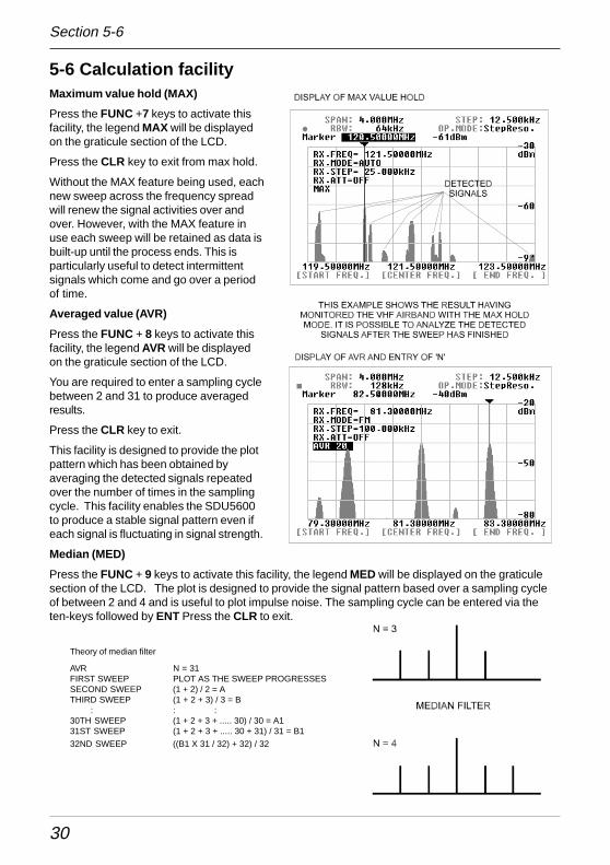
5-6 Calculation facilityMaximum value hold (MAX)
Press the FUNC +7 keys to activate thisfacility, the legend MAX will be displayedon the graticule section of the LCD.
Press the CLR key to exit from max hold.
Without the MAX feature being used, eachnew sweep across the frequency spreadwill renew the signal activities over andover. However, with the MAX feature inuse each sweep will be retained as data isbuilt-up until the process ends. This isparticularly useful to detect intermittentsignals which come and go over a periodof time.
Averaged value (AVR)
Press the FUNC + 8 keys to activate thisfacility, the legend AVR will be displayedon the graticule section of the LCD.
You are required to enter a sampling cyclebetween 2 and 31 to produce averagedresults.
Press the CLR key to exit.
This facility is designed to provide the plotpattern which has been obtained byaveraging the detected signals repeatedover the number of times in the samplingcycle. This facility enables the SDU5600to produce a stable signal pattern even ifeach signal is fluctuating in signal strength.
Median (MED)
Press the FUNC + 9 keys to activate this facility, the legend MED will be displayed on the graticulesection of the LCD. The plot is designed to provide the signal pattern based over a sampling cycleof between 2 and 4 and is useful to plot impulse noise. The sampling cycle can be entered via theten-keys followed by ENT Press the CLR to exit.
Theory of median filter
AVR N = 31FIRST SWEEP PLOT AS THE SWEEP PROGRESSESSECOND SWEEP (1 + 2) / 2 = ATHIRD SWEEP (1 + 2 + 3) / 3 = B
: : :30TH SWEEP (1 + 2 + 3 + ..... 30) / 30 = A131ST SWEEP (1 + 2 + 3 + ..... 30 + 31) / 31 = B1
32ND SWEEP ((B1 X 31 / 32) + 32) / 32
Section 5-6
31
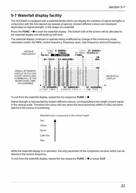
5-7 Waterfall display facilityThe SDU5600 is equipped with a waterfall facility which can display the variation of signal strengths inconjunction with the time lapsed (as sweeps progress). Sixteen different colours are employeddependant on signal strength, in the shape of a waterfall.
Press the FUNC + � to start the waterfall display. The bottom half of the screen will be allocated tothe waterfall display and will build-up with time.
The waterfall display continues to operate being unaffected by change of the monitoring mode,calculation mode, the RBW, centre frequency, frequency span, start frequency and end frequency.
Section 5-7
To exit from the waterfall display, repeat the key sequence FUNC + �
Signal strength is represented by sixteen different colours, corresponding to the height of each signalin the vertical scale. Therefore the colour will vary when the input sensitivity (AMPLITUDE) has beenaltered in the course of monitoring.
While the waterfall display is in operation, the only parameter of the companion receiver which can bealtered is the receive frequency.
To exit from the waterfall display, repeat the key sequence FUNC + � or press CLR
32
5-8 On/off of the displayed information
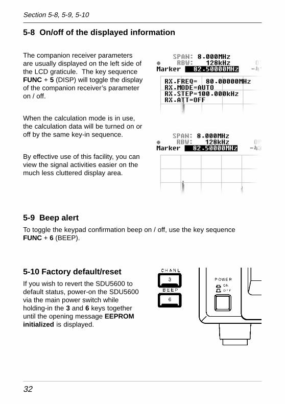
The companion receiver parametersare usually displayed on the left side ofthe LCD graticule. The key sequenceFUNC + 5 (DISP) will toggle the displayof the companion receiver’s parameteron / off.
When the calculation mode is in use,the calculation data will be turned on oroff by the same key-in sequence.
By effective use of this facility, you canview the signal activities easier on themuch less cluttered display area.
5-9 Beep alertTo toggle the keypad confirmation beep on / off, use the key sequenceFUNC + 6 (BEEP).
5-10 Factory default/resetIf you wish to revert the SDU5600 todefault status, power-on the SDU5600via the main power switch whileholding-in the 3 and 6 keys togetheruntil the opening message EEPROMinitialized is displayed.
Section 5-8, 5-9, 5-10
33
6. Operating the SDU5600This section will provide examples of operating the SDU5600 using the AR5000A+3 as companionreceiver. Refer to pages 10 to 12 of this manual for connection to the receiver.
Section 6, 6-1
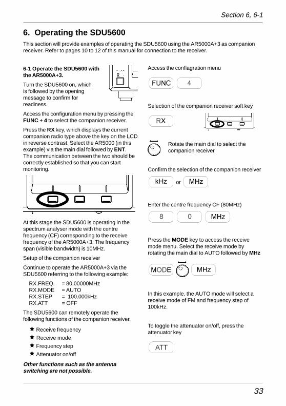
6-1 Operate the SDU5600 withthe AR5000A+3.
Turn the SDU5600 on, whichis followed by the openingmessage to confirm forreadiness.
Access the configuration menu by pressing theFUNC + 4 to select the companion receiver.
Press the RX key, which displays the currentcompanion radio type above the key on the LCDin reverse contrast. Select the AR5000 (in thisexample) via the main dial followed by ENT.The communication between the two should becorrectly established so that you can startmonitoring.
At this stage the SDU5600 is operating in thespectrum analyser mode with the centrefrequency (CF) corresponding to the receivefrequency of the AR5000A+3. The frequencyspan (visible bandwidth) is 10MHz.
Setup of the companion receiver
Continue to operate the AR5000A+3 via theSDU5600 referring to the following example:
RX.FREQ. = 80.00000MHzRX.MODE = AUTORX.STEP = 100.000kHzRX.ATT = OFF
The SDU5600 can remotely operate thefollowing functions of the companion receiver.
ê Receive frequency
ê Receive mode
ê Frequency step
ê Attenuator on/off
Other functions such as the antennaswitching are not possible.
Access the conflagration menu
Selection of the companion receiver soft key
Rotate the main dial to select thecompanion receiver
Confirm the selection of the companion receiver
or
Enter the centre frequency CF (80MHz)
Press the MODE key to access the receivemode menu. Select the receive mode byrotating the main dial to AUTO followed by MHz
In this example, the AUTO mode will select areceive mode of FM and frequency step of100kHz.
To toggle the attenuator on/off, press theattenuator key
34
6-2 Monitor the VHF FM band in the spectrum analyser modeContinue to operate the SDU5600 from section 6-1 where the SDU5600 / AR5000A+3 has been setin the spectrum monitoring mode.
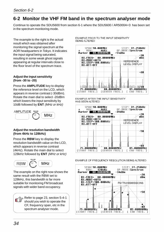
The example to the right is the actualresult which was obtained aftermonitoring the signal spectrum at theAOR headquarters in Tokyo. It indicatesthe input signal being saturated,resulting in some weak ghost signalsappearing at regular intervals close tothe floor level of the spectrum trace.
Adjust the input sensitivity(from -30 to -20)
Press the AMPLITUDE key to displaythe reference level on the LCD, whichappears in reverse contrast (-30dBm).Rotate the main dial to select -20dBmwhich lowers the input sensitivity by10dB followed by ENT (MHz or kHz)
Adjust the resolution bandwidth(from 4kHz to 128kHz)
Press the RBW key to display theresolution bandwidth value on the LCD,which appears in reverse contrast(4kHz). Rotate the main dial to select128kHz followed by ENT (MHz or kHz)
The example on the right now shows thesame result with the RBW set to128kHz, this bandwidth is far moresuitable for monitoring FM broadcastsignals with wider band occupancy.
Refer to page 23, section 5-4-1should you wish to operate theCF, frequency span, etc in thespectrum analyser mode.
Section 6-2
35
6-3 Monitor the FM broadcast band in the stepresolution modeThe following information explains how to change the monitoring mode fromthe default of spectrum analyser mode to the step resolution mode.
Press the FUNC + 2 (STEP), the SDU5600 will shift to Step Resolution modewith the legend StepReso. appearing on the LCD. The display step will beunchanged at this stage.
You may wish to change the display step to a 25kHz in order to make the taskof monitoring easier. Press the SPAN/STEP key, which results in the stepdisplay appearing in reverse contrast on the LCD. Type in the required stepsize via the ten-keys, in this example 2 5 followed by kHz
Rotate the main dial to move the marker sideways. It should beimmediately noticeable that the frequencies on active signals can befound in 25kHz steps, which is much more suitable for monitoringchannelised bands such as FM broadcast.
In the step resolution mode the rule is:1 displayed dot = 1 displayed step
The horizontal x-axis of the SDU5600 provides 320 dots.
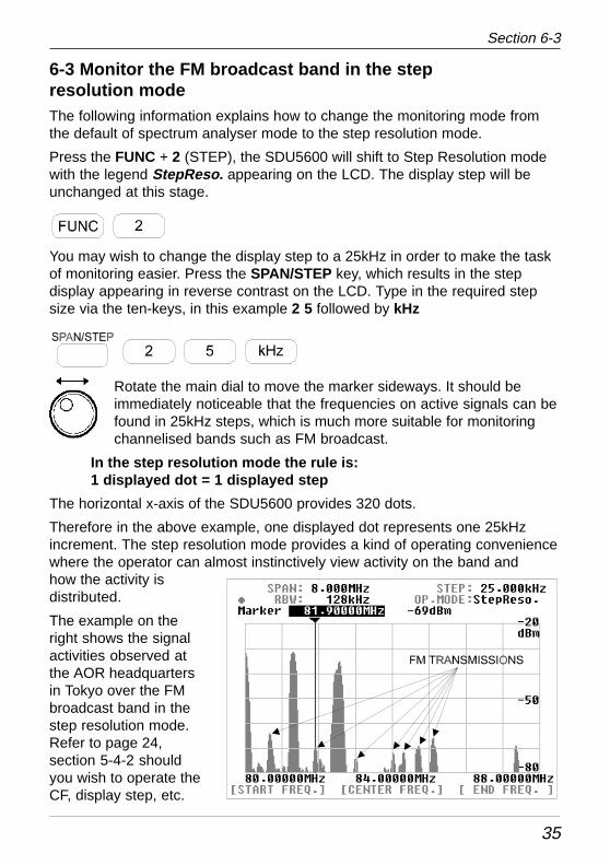
Therefore in the above example, one displayed dot represents one 25kHzincrement. The step resolution mode provides a kind of operating conveniencewhere the operator can almost instinctively view activity on the band andhow the activity isdistributed.
The example on theright shows the signalactivities observed atthe AOR headquartersin Tokyo over the FMbroadcast band in thestep resolution mode.Refer to page 24,section 5-4-2 shouldyou wish to operate theCF, display step, etc.
Section 6-3
36
6-4 Monitor the VHF air band in the channel scope mode.The VHF airband is allocated over the wide frequency band, It is therefore impossible to display theentire VHF airband on the SDU5600 at once. The channel scope mode however provides a veryconvenient method of monitoring the channelised frequency band through the use of both the markerand receive marker. Using this method, you can split the airband into small sections for quickinspection.
Change of the monitoring mode
To change to Channel Scope mode press FUNC + 3 (CHANL). The LCD legend OP.MODE:Channel confirms thatchannel scope mode has been engaged.
The LCD legend above [Ch.START] will display a frequency in revers contrast, thisis inviting you to key in a new start frequency via the ten-keys.
Enter a start frequency of 118MHz, if you make a mistake, press CLR to return tothe start entry position.
The LCD entry point will move to [Ch.STEP], enter a step frequency of 25kHz
The LCD entry point will move to [Ch. END], enter an end frequency of 122MHz
Note, the end frequency is always restricted under the rules:(CH.START) + [(CH.STEP) x 160]
and(CH.START) + 5MHz
Any incorrect entry of the end frequency will be alerted with the beep, and it will be automatically corrected to thenearest possible frequency.
Upon the successful entry of the end frequency the companion receiver will commence receiving on the startfrequency. Change the receive mode to AM for air band if required (or use AUTO mode), use the MODE key, maindial or SDU5600 and MHz key.
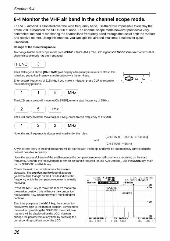
Rotate the main dial, which moves the markersideways. The receive marker legend appears(yellow outline triangle on the LCD) to indicate thefrequency which the companion receiver is actuallyreceiving.
Press the MK.F key to move the receive marker tothe marker position, this will move the companionreceive to the new frequency where monitoring willcontinue.
East time you press the MK.F key, the companionreceiver will shift to the marker position, as you movethe marker by rotating the SDU5600 main dial, twomarkers will be displayed on the LCD. You canchange the parameters at any time by pressing thecorresponding soft key under the LCD.
Section 6-4
37
6-5 Suitable applications of each monitoring mode
A summary of the three monitoring modes and suitable applications is givenhere:
Spectrum analyser mode
This mode is the DEFAULT and most common monitoring mode among thethree. It is suited to the monitoring of permanent or intermittent signals ornoise. The CF (centre frequency) and SPAN (visible bandwidth) are the maincriteria to be specified.
Step resolution mode
This mode is suited best to monitor signals which are allocated with certainintervals over the band spectrum. The STEP is the criteria to be specified inplace of the SPAN, so that one dot is equal to one step on the display.
Channel scope mode
This mode is best suited to monitor known channelised frequency spectrumssuch as VHF airband and FM sections or broadcast and ham radio bands.The start frequency, end frequency and step have to be specified. There is noconcept of CF applied to this mode. It is most convenient to follow and listento the various signals by using both marker and receive markers.
Section 6-5
38
7. Useful Information
The SDU5600 has been designed to operate with a wide-band companion receiver such as theAR5000A. Therefore, there are some differences in operating characteristics with the unit whencompared with the spectrum analysers which are designed for more general testing / measuringapplications. It is advisable that you take into account the following information while making yourselffamiliar with the SDU5600.
Signal strengthThe signal strength which the SDU5600 indicates is measured at the RF input of the SDU (not the signal strength of the companionreceiver at the antenna terminal). If the radio provides a gain / loss from the aerial input to IF output, the calibration of displayed signalstrength will be affected. Most receivers provide a POSITIVE gain of +10dB or so. The receivers AGC and attenuator will also affectresults.
Frequency characteristics of the companion receiverThe SDU5600 operates with a wide span of frequency (up to 10MHz band span). It must be noted that the companion receiver’s RFcircuit and / or IF filter configuration may affect the spectrum monitoring with some interference being observed. In particular, when thewider band span has been selected such as a 10MHz, the far ends of the band edges are most affected depending on characteristicsof the receiver in use. The AR5000A is usable over 10MHz bandwidth, as is the AR3000A, however the output level of the AR8600/MK2 drops beyond 4MHz or so.
Excessive input from the receiverWhile receiving strong signals (e.g. broadcast station) with an external aerial connected to the companion receiver, the noise floormay appear to be incorrectly lifted due to distortion from the receiver. Use of the attenuator of the receiver may help reduce thesephenomena... however, generally speaking the front end selectivity of the companion receiver is beneficial compared to a directly fedspectrum analyser.
Selection of RBWWhen monitoring the signals of broader bandwidth with the narrower RBW selected, the displayed signal strength may appearreduced (less accurate) due to the fact that only part of the energy from the broader bandwidth can pass through the narrowersampling filter, resulting in loss of signal strength to some extent. When monitoring wider signals (such as FM broadcast), use a widerRBW such as 128kHz.
AGC action of the companion receiverIt must be noted that the AGC action of the companion receiver may affect the spectrum monitoring by the SDU5600. It may beobserved that the overall signal strength has dropped when abrupt changes in receiving conditions have occurred (for example, whenquickly tuning from a weak signal to a strong signal). This is because the input from the receiver’s IF is significantly reduced by AGCaction. Switching the companion receivers AGC off may eliminate this effect but the reception will become unstable and distorted withAGC off.
Image signalOccasionally false signals (spurious image signal) can be spotted on the display, sometimes moving at random, sometimes to theopposite direction while monitoring the spectrum. This is due to the image signals which are generated by characteristics of thecompanion receivers superheterodyne circuit design or intermodulation products, ALL receivers will present this affect to somedegree.
With the SDU5600 operating at its widest sweep range (10MHz) when coupled to an AR5000A , an unwanted spurious signal can beobserved approximately 4.8MHz away from the centre frequency (moves slightly with AR5000A frequency). This is present at allfrequencies although it will jump to the other side of the screen when the AR5000 is tuned above 1.4GHz.
The spurii appears to be leakage of the 2nd local oscillator DDS signal at 5.8MHz to 6.7MHz (hence when viewed from the IFfrequency of 10.7MHz becomes 4.9 to 4.0MHz away). This is not a problem during normal receive with the AR5000A as the 10.7MHzfilter removes any signal but is present at the IF output taken before the filter. It is also not a problem if the sweep width on theSDU5600 is reduced slightly.
To address this, select a bandwidth of about 9.8MHz rather than 10MHz, so the spurii drops off the edge of the display. The spurii isusually in the area of -70dBm to -60dBm.
The AR8600/MK2 produces a 455kHz image, its a compromise of design and has to be worked around.
RF earthOf course all electrical equipment produces some noise, especially where large displays are involved. Connecting a good RF earth tothe equipment can help with general low level spurii... the AC adapter is not earthed, avoid earth loops.
Minimum frequency spanThe SDU5600 has a minimum frequency span of 160kHz (0.160MHz). It is not possible to set the frequency span narrower than160kHz.
Section 7
39
8. SDU5600 Command ListThe SDU5600 can be operated via PC using the RS232 port.
8-1 Communication parameter and connecting leadThe SDU5600 and a PC should be connected using a straight cable betweenthe [PC I/F] socket and the serial port of the PC. The SDU5600 port is MALE,so the PC lead must have a female connector or a gender changer will have tobe employed.
Communications parameters of the SDU5600
Baud rate 9600bps
Data length 8 bit
Parity None
Stop bit 2 bit
Flow control RTS/CTS
8-2 DelimiterA brief description of delimeter and response format is given here.
Delimiter
Each command from the PC to SDU5600 is defined by:
<CR> 0x0d in 16-bit form
or
<CR><LF> 0x0d,0x0a in hexadecimal format
Note: <LF> will be ignored
Response when the command has been correct:
<SP><CR><LF> 0x20,0x0d,0x0a in hexadecimal format
Response when the command has been incorrect:
?<CR><LF> 0x3f,0x0d,0x0a in hexadecimal format
Response to the read command:
Following the output of the parameter, the correct response should read
<SP><CR><LF> 0x20,0x0d,0x0a in hexadecimal format
Section 8, 8-1, 8-2
40
8-3 Basic format of the commandEach command to be sent to the SDU5600 consists of 4 letters (upper case) inASCII code with appropriate parameters followed by <CR><LF>.
Each letter represents the following:
(1) First letter Either W for write or R for read
(2) Second letter Line of command such as S forspectrum analysis, V for visualset-up, U for user interface andI for information
(3 & 4) Third and Fourth letter Categories of each line of command
8-4 RS232 command listCommands are divided into four categories:
S = Spectrum analysis
V = Visual command
U = User Interface
I = Information
Microsoft Windows® Hyper Terminal® may be used to control the SDU5600 or you may write yourown software.
An example of command format is given here:
RSCF<CR> Response: SCF79.5<SP><CR><LF>
In this example, the centre frequency is read.
Command = Read
Category = Spectrum analysis
Type of command (abbreviation) = CF
Parameter (variable) = Not used in this example
Example of input = RSCF<CR> Response from SDU5600 = SCF79.5<SP><CR><LF>
A correct WRITE command results in the action being carried out and <CR><CR><LF> beingreturned. An incorrect command results in a question mark “?” followed by <CR><LF> beingreturned.
Section 8-3, 8-4
41
Spectrum analysisCommand : WSCF Function : SET CENTER FREQUENCY Command category: WRITEParameter : Min- Max (in MHz )Example : WSCF79.5<CR><LF> Response: if correct: <SP><CR><LF>
if incorrect: ?<CR><LF>Remarks: Frequency entry for out of receive range will be respond by ?<CR><LF>, and thecommand will be ignored.
Command : RSCF Function : READ CENTER FREQUENCY Command category: READParameter : N/AExample : RSC<CR><LF> Response: SCF79.5<SP><CR><LF>Remarks: Frequency is displayed in MHz.
Command : WSSP Function : SET SPAN FREQUENCY Command category: WRITEParameter : 0.16 ~ 10 (MHz)Example : WSSP0.62<CR><LF> Response: if correct: <SP><CR><LF>
if incorrect: ?<CR><LF>Remarks: Data entry for out of range will be respond by ?<CR><LF>, and the command will beignored.
Command : RSSP Function : READ SPAN FREQUENCY Command category: READParameter : N/AExample : RSSP<CR><LF> Response: SSP0.62<SP><CR><LF>Remarks: Frequency is displayed in MHz.
Command : WSBW Function : SET RBW Command category: WRITEParameter : 1 ~ 4Example : WSBW1<CR><LF> Response: if correct: <SP><CR><LF>
if incorrect: ?<CR><LF>Remarks: Parameter vs. RBW is as follows: 1 = 4 KHz, 2 = 32 KHz, 3 = 64 KHz, 4 = 128 KHzData entry for out of range will be respond by ?<CR><LF>, and the command will be ignored.
Command : RSBW Function : READ RBW Command category: READParameter : N/AExample : RSBW<CR><LF> Response: SBW4<SP><CR><LF>Remarks: Parameter vs. RBW is as follows: 1 = 4 KHz, 2 = 32 KHz, 3 = 64 KHz, 4 = 128 KHz.
Command : WSGN Function : SET AMPLITUDE Command category: WRITEParameter : -30 ~ 0Example : WSGN-30<CR><LF> Response: if correct: <SP><CR><LF>
if incorrect: ?<CR><LF>Remarks: Amplitude is set in 10 incremental. Data entry for out of range will be respond by?<CR><LF>, and the command will be ignored.
Command : WSCM Function : SET CURSOR Command category: WRITEParameter : 1 ~ 3Example : WSCM3<CR><LF> Response: if correct: <SP><CR><LF>
if incorrect: ?<CR><LF>Remarks: Parameter : 1 = MARKER, 2 = PEAK, 3 = C-PEAK To use this command, you need to setthe trigger level by using the WSTL command. Data entry for out of range will be respond by?<CR><LF>, and the command will be ignored.
Command : RSCM Function : READ CURSOR Command category: READParameter : N/AExample : RSCM<CR><LF> Response: SCM1<SP><CR><LF>Remarks: Parameter : 1 = MARKER, 2 = PEAK, 3 = C-PEAK
Section 8-4
42
Command : WSTL Function : SET PEAK TRIGGER LEVEL Command category: WRITEParameter : -90 ~ 0Example : WSTL-80<CR><LF> Response: if correct: <SP><CR><LF>
if incorrect: ?<CR><LF>Remarks: Data entry for out of range will be respond by ?<CR><LF>, and the command will beignored.
Command : RSTL Function : READ PEAK TRIGGER LEVEL Command category: READParameter : N/AExample : RSTL<CR><LF> Response: STL-80<SP><CR><LF>Remarks: Read the trigger level in the Peak mode.
Command : WSDM Function : SET DATA MODE Command category: WRITEParameter : 1 ~ 4Example : WSDM2<CR><LF> Response: if correct: <SP><CR><LF>
if incorrect: ?<CR><LF>Remarks: Parameter: 1 = NORMAL, 2 = AVR, 3 = MAX, 4 = MED If AVR or MED is selected, youneed to set the WSME command before executing the command. Data entry for out of range willrespond by ?<CR><LF>, and the command will be ignored.
Command : RSDM Function : READ DATA MODE Command category: READParameter : N/AExample : RSDM<CR><LF> Response: SDM3<SP><CR><LF>Remarks: Parameter: 1 = NORMAL, 2 = AVR, 3 = MAX, 4 = MED
Command : WSAV Function : SET AVR SAMPLING Command category: WRITEParameter : 2 ~ 31Example : WSAV10<CR><LF> Response: if correct: <SP><CR><LF>
if incorrect: ?<CR><LF>Remarks: Set AVR sampling and set the DATA mode to AVR. Data entry for out of range will respondby ?<CR><LF>, and the command will be ignored.
Command : RSAV Function : READ AVR SAMPLING Command category: READParameter : N/AExample : RSAV<CR><LF> Response: SAV10<SP><CR><LF>
Command : WSME Function : SET MED SAMPLING Command category: WRITEParameter : 2 ~ 4Example : WSME4<CR><LF> Response: if correct: <SP><CR><LF>
if incorrect: ?<CR><LF>Remarks: Set MED sampling and set the DATA mode to MED. Data entry for out of range willrespond by ?<CR><LF>, and the command will be ignored.
Command : RSME Function : READ MED SAMPLING Command category: READParameter : N/AExample : RSMED<CR><LF> Response: SMED4<SP><CR><LF>
Section 8-4
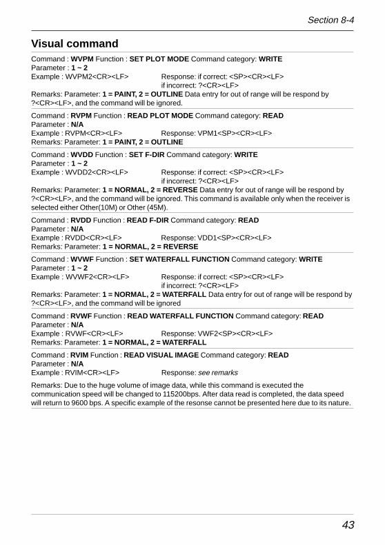
43
Visual commandCommand : WVPM Function : SET PLOT MODE Command category: WRITEParameter : 1 ~ 2Example : WVPM2<CR><LF> Response: if correct: <SP><CR><LF>
if incorrect: ?<CR><LF>Remarks: Parameter: 1 = PAINT, 2 = OUTLINE Data entry for out of range will be respond by?<CR><LF>, and the command will be ignored.
Command : RVPM Function : READ PLOT MODE Command category: READParameter : N/AExample : RVPM<CR><LF> Response: VPM1<SP><CR><LF>Remarks: Parameter: 1 = PAINT, 2 = OUTLINE
Command : WVDD Function : SET F-DIR Command category: WRITEParameter : 1 ~ 2Example : WVDD2<CR><LF> Response: if correct: <SP><CR><LF>
if incorrect: ?<CR><LF>Remarks: Parameter: 1 = NORMAL, 2 = REVERSE Data entry for out of range will be respond by?<CR><LF>, and the command will be ignored. This command is available only when the receiver isselected either Other(10M) or Other (45M).
Command : RVDD Function : READ F-DIR Command category: READParameter : N/AExample : RVDD<CR><LF> Response: VDD1<SP><CR><LF>Remarks: Parameter: 1 = NORMAL, 2 = REVERSE
Command : WVWF Function : SET WATERFALL FUNCTION Command category: WRITEParameter : 1 ~ 2Example : WVWF2<CR><LF> Response: if correct: <SP><CR><LF>
if incorrect: ?<CR><LF>Remarks: Parameter: 1 = NORMAL, 2 = WATERFALL Data entry for out of range will be respond by?<CR><LF>, and the command will be ignored
Command : RVWF Function : READ WATERFALL FUNCTION Command category: READParameter : N/AExample : RVWF<CR><LF> Response: VWF2<SP><CR><LF>Remarks: Parameter: 1 = NORMAL, 2 = WATERFALL
Command : RVIM Function : READ VISUAL IMAGE Command category: READParameter : N/AExample : RVIM<CR><LF> Response: see remarks
Remarks: Due to the huge volume of image data, while this command is executed thecommunication speed will be changed to 115200bps. After data read is completed, the data speedwill return to 9600 bps. A specific example of the resonse cannot be presented here due to its nature.
Section 8-4
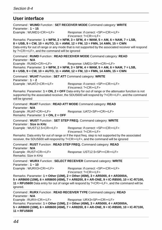
44
User interfaceCommand : WUMD Function : SET RECEIVER MODE Command category: WRITEParameter : 1 ~ 15Example : WUMD1<CR><LF> Response: if correct: <SP><CR><LF>
if incorrect: ?<CR><LF>Remarks: Parameter: 1 = WFM, 2 = NFM, 3 = SFM, 4 = WAM, 5 = AM, 6 = NAM, 7 = LSB,8 = USB, 9 = CW, 10 = AUTO, 11 = AMW, 12 = FM, 13 = FMN, 14 AMN, 15 = CWNData entry for out of range or any mode that is not supported by the associated receiver will respondby ?<CR><LF>, and the command will be ignored
Command : RUMD Function : READ RECEIVER MODE Command category: READParameter : N/AExample : RUMD<CR><LF> Response: UMD1<SP><CR><LF>Remarks: Parameter: 1 = WFM, 2 = NFM, 3 = SFM, 4 = WAM, 5 = AM, 6 = NAM, 7 = LSB,8 = USB, 9 = CW, 10 = AUTO, 11 = AMW, 12 = FM, 13 = FMN, 14 AMN, 15 = CWN
Command : WUAT Function : SET ATT Command category: WRITEParameter : 1 ~ 2Example : WUAT2<CR><LF> Response: if correct: <SP><CR><LF>
if incorrect: ?<CR><LF>Remarks: Parameter: 1 = ON, 2 = OFF Data entry for out of range or the attenuator function is notsupported by the associated receiver, the SDU5600 will respond by ?<CR><LF>, and the commandwill be ignored
Command : RUAT Function : READ ATT MODE Command category: READParameter : N/AExample : RUAT<CR><LF> Response: UAT2<SP><CR><LF>Remarks: Parameter: 1 = ON, 2 = OFF
Command : WUST Function : SET STEP FREQ. Command category: WRITEParameter : Size in KHzExample : WUST12.5<CR><LF> Response: if correct: <SP><CR><LF>
if incorrect: ?<CR><LF>Remarks: Data entry for out of range or if the input freq. step is not supported by the associatedreceiver, the SDU5600 will respond by ?<CR><LF>, and the command will be ignored
Command : RUST Function : READ STEP FREQ. Command category: READParameter : N/AExample : RUST<CR><LF> Response: UST12.5<SP><CR><LF>Remarks: Size in KHz
Command : WURX Function : SELECT RECEIVER Command category: WRITEParameter : 1 ~ 10Example : WURX3<CR><LF> Response: if correct: <SP><CR><LF>
if incorrect: ?<CR><LF>Remarks: Parameter: 1 = Other (10M), 2 = Other (45M), 3 = AR5000, 4 = AR3000A,5 = AR8600 (10M), 6 = AR8600 (45M), 7 = AR8200, 8 = AR-ONE, 9 = IC-R8500, 10 = IC-R7100,11 = RFU5600 Data entry for out of range will respond by ?<CR><LF>, and the command will beignored.
Command : RURX Function : READ RECEIVER TYPE Command category: READParameter : N/AExample : RURX<CR><LF> Response: URX3<SP><CR><LF>Remarks: Parameter: 1 = Other (10M), 2 = Other (45M), 3 = AR5000, 4 = AR3000A,5 = AR8600 (10M), 6 = AR8600 (45M), 7 = AR8200, 8 = AR-ONE, 9 = IC-R8500, 10 = IC-R7100,11 = RFU5600
Section 8-4
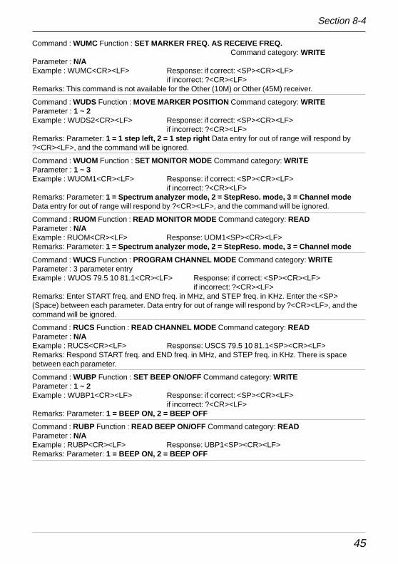
45
Command : WUMC Function : SET MARKER FREQ. AS RECEIVE FREQ. Command category: WRITE
Parameter : N/AExample : WUMC<CR><LF> Response: if correct: <SP><CR><LF>
if incorrect: ?<CR><LF>Remarks: This command is not available for the Other (10M) or Other (45M) receiver.
Command : WUDS Function : MOVE MARKER POSITION Command category: WRITEParameter : 1 ~ 2Example : WUDS2<CR><LF> Response: if correct: <SP><CR><LF>
if incorrect: ?<CR><LF>Remarks: Parameter: 1 = 1 step left, 2 = 1 step right Data entry for out of range will respond by?<CR><LF>, and the command will be ignored.
Command : WUOM Function : SET MONITOR MODE Command category: WRITEParameter : 1 ~ 3Example : WUOM1<CR><LF> Response: if correct: <SP><CR><LF>
if incorrect: ?<CR><LF>Remarks: Parameter: 1 = Spectrum analyzer mode, 2 = StepReso. mode, 3 = Channel modeData entry for out of range will respond by ?<CR><LF>, and the command will be ignored.
Command : RUOM Function : READ MONITOR MODE Command category: READParameter : N/AExample : RUOM<CR><LF> Response: UOM1<SP><CR><LF>Remarks: Parameter: 1 = Spectrum analyzer mode, 2 = StepReso. mode, 3 = Channel mode
Command : WUCS Function : PROGRAM CHANNEL MODE Command category: WRITEParameter : 3 parameter entryExample : WUOS 79.5 10 81.1<CR><LF> Response: if correct: <SP><CR><LF>
if incorrect: ?<CR><LF>Remarks: Enter START freq. and END freq. in MHz, and STEP freq. in KHz. Enter the <SP>(Space) between each parameter. Data entry for out of range will respond by ?<CR><LF>, and thecommand will be ignored.
Command : RUCS Function : READ CHANNEL MODE Command category: READParameter : N/AExample : RUCS<CR><LF> Response: USCS 79.5 10 81.1<SP><CR><LF>Remarks: Respond START freq. and END freq. in MHz, and STEP freq. in KHz. There is spacebetween each parameter.
Command : WUBP Function : SET BEEP ON/OFF Command category: WRITEParameter : 1 ~ 2Example : WUBP1<CR><LF> Response: if correct: <SP><CR><LF>
if incorrect: ?<CR><LF>Remarks: Parameter: 1 = BEEP ON, 2 = BEEP OFF
Command : RUBP Function : READ BEEP ON/OFF Command category: READParameter : N/AExample : RUBP<CR><LF> Response: UBP1<SP><CR><LF>Remarks: Parameter: 1 = BEEP ON, 2 = BEEP OFF
Section 8-4
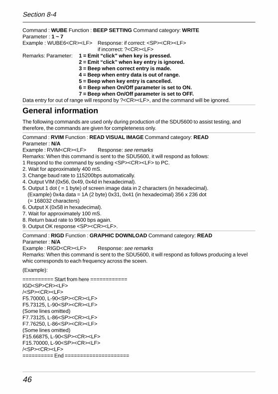
46
Command : WUBE Function : BEEP SETTING Command category: WRITEParameter : 1 ~ 7Example : WUBE6<CR><LF> Response: if correct: <SP><CR><LF>
if incorrect: ?<CR><LF>Remarks: Parameter: 1 = Emit “click” when key is pressed.
2 = Emit “click” when key entry is ignored.3 = Beep when correct entry is made.4 = Beep when entry data is out of range.5 = Beep when key entry is cancelled.6 = Beep when On/Off parameter is set to ON.7 = Beep when On/Off parameter is set to OFF.
Data entry for out of range will respond by ?<CR><LF>, and the command will be ignored.
General informationThe following commands are used only during production of the SDU5600 to assist testing, andtherefore, the commands are given for completeness only.
Command : RVIM Function : READ VISUAL IMAGE Command category: READParameter : N/AExample : RVIM<CR><LF> Response: see remarksRemarks: When this command is sent to the SDU5600, it will respond as follows:1 Respond to the command by sending <SP><CR><LF> to PC.2. Wait for approximately 400 mS.3. Change baud rate to 115200bps automatically.4. Output VIM (0x56, 0x49, 0x4d in hexadecimal).5. Output 1 dot ( = 1 byte) of screen image data in 2 characters (in hexadecimal). (Example) 0x4a data = 1A (2 byte) 0x31, 0x41 (in hexadecimal) 356 x 236 dot (= 168032 characters)6. Output X (0x58 in hexadecimal).7. Wait for approximately 100 mS.8. Return baud rate to 9600 bps again.9. Output OK response <SP><CR><LF>.
Command : RIGD Function : GRAPHIC DOWNLOAD Command category: READParameter : N/AExample : RIGD<CR><LF> Response: see remarksRemarks: When this command is sent to the SDU5600, it will respond as follows producing a levelwhic corresponds to each frequency across the sceen.
(Example):
========== Start from here ============IGD<SP>CR><LF>/<SP><CR><LF>F5.70000, L-90<SP><CR><LF>F5.73125, L-90<SP><CR><LF>(Some lines omitted)F7.73125, L-86<SP><CR><LF>F7.76250, L-86<SP><CR><LF>(Some lines omitted)F15.66875, L-90<SP><CR><LF>F15.70000, L-90<SP><CR><LF>/<SP><CR><LF>========== End =====================
Section 8-4
47
Produces a ‘pair’ of data values comprising of frequency and its level at MHz order which is defined(sandwiched) by / /. In reality, there may be a discrepancy of +/- 1dBm between the value of themarker on the LCD and the level of the same marker which is calculated by this command.
Command : RICD Function : CURSOR DOWNLOAD Command category: READParameter : N/AExample : RICD<CR><LF> Response: see remarksRemarks: Read output level of the cursor frequency.
(Example):
========== Start from here ============f10.70000, l-78<SP>CR><LF>========== End =====================
Note: Use small F or L (not a capital) for this command. This produces the information in one lineunlike the download plot information. In reality, there may be a discrepancy of +/- 1dBm between thevalue of the marker on the LCD and the level of the same marker which is calculated by thiscommand.
Command : RIFD Function : HIGH SPEED DATA DOWNLOAD Command category: READParameter : N/AExample : RIFD<CR><LF> Response: see remarksRemarks: Read output level on each frequency on the screen as 1 byte data.
(Example):
========== Start from here ============IFD<SP><CR><LF><SP>CR><LF>(Some lines omitted, these are level data area.) #%$-+#!(Some lines omitted) <SP><SP><SP><CR><LF>========== End =====================
The level data per frequency will be presented in ASCII code which has been obtained by calculationof the label, 100 + 0x20.
Note: Use small F or L (not a capital) for this command. In reality, there may be a discrepancy of +/-1dBm between the value of the marker on the LCD and the level of the same marker which iscalculated by this command.
Command : RIVE Function : READ FIRMWARE VERSION Command category: READParameter : N/AExample : RIVE<CR><LF> Response: see remarksRemarks: (Example):
========== Start from here ============IVE<SP>Ver.<SP>007<SP>307C<SP><SP><CR><LF>========== End =====================
Produces the version information followed by IVE<SP>
Section 8-4
48
Notes for programmersGenerally speaking the screen dump is preferable if graphic info (data) iswanted. On the other hand the array of frequency / level can better serve ifnumerical data is demanded. The array of frequency / level is faster in transfertime from the SDU5600 to the PC.
The SDU5600 accepts commands either from the PC or from its own frontpanel on a first come first serve basis. For example the PC has sent data toswitch the SPAN bandwidth to 10MHz followed by data from the front panelsetting the same parameter to 5MHz. The SDU5600 will perform the change to10MHz then to 5MHz.
AOR is considering commissioning a PC control package for the SDU5600,keep an eye on the AOR web site for possible information:
www.aorja.com
www.aoruk.com
www.aorusa.com
Section 8-4
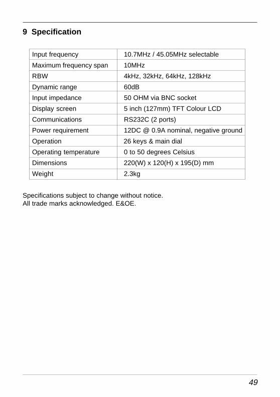
49
9 Specification
Input frequency 10.7MHz / 45.05MHz selectable
Maximum frequency span 10MHz
RBW 4kHz, 32kHz, 64kHz, 128kHz
Dynamic range 60dB
Input impedance 50 OHM via BNC socket
Display screen 5 inch (127mm) TFT Colour LCD
Communications RS232C (2 ports)
Power requirement 12DC @ 0.9A nominal, negative ground
Operation 26 keys & main dial
Operating temperature 0 to 50 degrees Celsius
Dimensions 220(W) x 120(H) x 195(D) mm
Weight 2.3kg
Specifications subject to change without notice.All trade marks acknowledged. E&OE.

50
Notes:

51
52
AOR Ltd2-6-4 Misuji, Taito-ku, Tokyo 111, Japan.Tel: +81 3 3865 1695 Fax: +81 3 3865 1697
[email protected] www.aorja.comAOR (UK) Ltd
4E East Mill, Bridgefoot, Belper, Derbys DE56 2UA, EnglandTel: +44 1773 880788 Fax: +44 1773 880780
[email protected] www.aoruk.comAOR USA INC.,
20655 S. Western Ave., Suite 112, Torrance, CA 90501 USATel: 310 787 8615 Fax: 310 787 [email protected] www.aorusa.com
®
0104