ferrites and accessories - tdk-electronics.tdk.com · considered the most important transformer...
TRANSCRIPT

EPCOS AG 2017. Reproduction, publication and dissemination of this publication, enclosures hereto and theinformation contained therein without EPCOS’ prior express consent is prohibited.
EPCOS AG is a TDK Group Company.
Ferrites and accessories
Application notes
Date: May 2017

2 5/17Please read Cautions and warnings and Important notes at the end of this document.
Filter applicationsApplication notes
Application notes
1 Cores for filter applications1.1 Gapped cores for filter/resonant circuits
Gapped cores are therefore always used in high quality circuits (for materials see applicationsurvey).In the case of small air gaps (max. 0.2 mm) the air gap can be ground into only one core half. In thiscase the half with the ground air gap bears the stamp. The other half is blank.The air gap enables the losses in the small-signal area and the temperature coefficient to be re-duced by a factor of μe/μi in the small-signal area. More important, however, is that close AL valuetolerances can be achieved.The rated AL values for cores with ground air gap can be obtained from the individual data sheets.The data for the individual cores also include the effective permeability μe used to approximatelydetermine the effective loss factor tan δe and the temperature coefficient of the effective permeabil-ity αe from the ring core characteristics (see table of material properties).It should be noted at this point that in cores with a larger air gap the stray field in the immediatevicinity of the air gap can cause additional eddy current losses in the copper winding. If the coil qual-ity must meet stringent requirements, it is therefore advisable to wind several layers of polystyrene,nylon tape or even FPC film under the wire in the part of the winding that is in the proximity of theair gap; with a 3-section coil former this would be the part of the center section near the air gap.
Basic requirements:■ Low tan δ■ Close tolerance for AL value■ Close tolerance for temperature coefficient■ Low disaccommodation factor DF■ Wide adjustment range
CL
Figure 10Schematic drawing showing the construction ofa P or RM core set with a total air gap s, com-prising 2 core halves (1 and 2), threaded part (3)and padded winding (4)

3 5/17Please read Cautions and warnings and Important notes at the end of this document.
1.2 P and RM cores with threaded sleevesMost of P and RM cores are supplied with a glued-in threaded sleeve. EPCOS uses automaticmachines featuring high reliability in dosing of the adhesive and in positioning the threaded sleevein the core.The tight fit of the threaded sleeve is regularly checked – including a humid atmosphere of40 °C/93% r.h. (to IEC 60068-2-3-78) over 4 days – and also by periodic tests over 3 weeks. Theusual bonding strengths of 20 N for ∅ 2 mm holes (e.g. for RM 5) and 30 N for ∅ 3 mm holes (e.g.for P 14 × 11, RM 6) are greatly exceeded, reaching an average of >100 N. The threaded sleeve iscontinuously checked for proper centering. Overall, the controlled automated procedure guaranteeshigher reliability than manual gluing with its unavoidable inadequacies. Owing to the porosity of theferrite, tension of the ferrite structure due to hardened adhesive that has penetrated cannot alwaysbe avoided. Hence, the relative temperature coefficient αF may be increased by approximately0.2 · 10-6/K.
1.3 Typical calculation of a resonant circuit inductorThe following example serves to illustrate the dependencies to be considered when designing aresonant circuit inductor:A SIFERRIT pot core inductor is required with an inductance of L = 640 μH and a minimum qualityfactor Q = 400 (tan δL = 1/Q = 2.5 · 10-3) for a frequency of 500 kHz. The temperature coefficient αeof this inductor should be 100 · 10-6/K in the temperature range +5 to +55 °C.
a) Choice of materialAccording to the table of material properties and the tan δ/μi curves (see chapter “SIFERRITmaterials”) the material M33, for example, can be used for 500 kHz.
b) Choice of AL valueThe Q and temperature coefficient requirements demand a gapped pot core. The relativetemperature coefficient αF of SIFERRIT M33 according to the table of material properties is onaverage about 1,6 · 10-6/K. Since the required αe value of the gapped P core should be about100 · 10-6/K, the effective permeability is
With pot core P 18 × 11 (B65651): μe = 47.9 for AL = 100 nH.With pot core P 22 × 13 (B65661): μe = 39.8 for AL = 100 nH.
c) Choice of winding materialRF litz wire 20 × 0.05 with single natural silk covering is particularly suitable for frequencies around500 kHz. The overall diameter of the wire including insulation of 0.367 mm and the averageresistivity of 0.444 Ω/m are obtained from the litz-wire table (refer to pertinent standard). It isrecommended that the actual overall diameter always be measured, and this value used for thecalculation.
αFαeμe------= μe
αeα μi⁄------------ 100 10 6–⋅ K ⁄ 1
1.6 10 6–⋅ K ⁄----------------------------------⋅ 62.5= = =
Filter applicationsApplication notes

4 5/17Please read Cautions and warnings and Important notes at the end of this document.
d) Number of turns and type of coreFor an AL value of 100 nH and an inductance of 640 μH the equation N = (L/AL)1/2 yields 80 turns.The nomogram for coil formers shows that for a wire with an external diameter of 0.367 mm the two-section coil former for core type P 18 × 11 can easily take 80 turns. This core type can therefore beused with a one-section coil former.
e) Length of wire and DC resistanceThe length of an average turn lN on the above former is 35.6 mm. The length of litz wire necessaryfor the coil is therefore 80 · 35.6 mm = 2848 mm plus say 2 · 10 cm for the connections, giving a totallength of 3.04 m. The average resistivity of this wire is 0.444 Ω/m; the total DC resistance is thus3.04 m · 0,444 Ω/m ≈ 1,35 Ω. It should be noted that the length of an average turn lN given in theindividual data sheets always refers to the fully wound former. If the former is not fully wound, thelength of an average turn must be corrected according to the extent of the winding.
f) Checking the temperature coefficientThe core P 18 × 11 with AL = 100 nH has an effective permeability μe = 47.9. SIFERRIT M33 has arelative temperature coefficient αF ≈ 1.6 · 10-6/K; therefore the following temperature coefficient canbe calculated
Actual measurement yielded 90 · 10-6/K.It should be pointed out that with pot cores the temperature coefficient of the unwound coil hasalmost no influence since the flux density lies primarily in the core.For effective permeabilities μe <80, however, due to the influence of the winding an additionaltemperature coefficient of approx. (10 to 30) · 10-6/K must be included in the calculation.
αe μe αF⋅ 47.9 1.6 10 6– K§⋅ ⋅ 76.6 10 6– K§⋅= = =
Filter applicationsApplication notes

5 5/17Please read Cautions and warnings and Important notes at the end of this document.
2 Cores for broadband transformers
2.1 Precision-ground, ungapped cores for broadband transformersFor fields of application such as matching transformers in digital telecommunication networks orpulse signal transformers, either cores which form a closed magnetic circuit (toroids, double E ordouble-aperture cores) or paired core sets without air gap are used. In order to achieve the highestpossible effective permeability here, these cores are precision ground with residual air gapss ~ 1 μm. By selecting the low-profile core types, the AL value can be further increased, and thenumber of turns reduced.For this reason, RM and pot cores made of materials N30, T38, T46 and T66 are especially suitablefor these applications. For high-frequency applications, N22, M33 and K1 are suitable.
2.2 Fundamentals for broadband transformers in the range 10 kHz to over 1 GHz – anexample
Broadband transformers are constructed primarily using closed core shapes, i.e. toroids anddouble-aperture cores. Divided core designs such as P/RM cores or small E/ER cores, which allowmore simple winding, are particularly suitable for transformers up to approximately 200 MHz.The bandwidth Δ f = foG – fuG (foG = upper cut-off frequency, fuG = lower cut-off frequency) isconsidered the most important transformer characteristic.Cut-off frequency: Frequency at which the voltage at the transformer drops by 3 dB ( –30%)The following holds true for circuit quality Q >10 (typical value):
fr = Resonance frequencyRi = Internal resistance of generator (normally, Ri << loss resistance of ferrite)LH = Main inductanceC0 = Winding capacitance
General requirements:■ High AL values ( high effective permeability) to
restrict number of turns■ Good broadband properties, i.e. high imped-
ance up to highest possible frequencies■ Low total harmonic distortion ( low hysteresis
material constant ηB)■ Low sensitivity to superimposed DC currents
( highest possible values for TC and BS)■ Low tan δ for high-frequency applications
fΔfrRi-----
LHC0-------⋅=
Broadband transformersApplication notes

6 5/17Please read Cautions and warnings and Important notes at the end of this document.
Transmission loss curve:
Example: 1 : 1 transformer based on E6.3/T38 with 2 ×10 turns
2.3 Low-distortion transformers for digital data transmission (ISDN, xDSL)The digital transmission technologies over copper like ISDN, HDSL (high-rate digital subscriberline) and ADSL (asymmetric digital subscriber line) require very small harmonic distortion in orderto maintain maximal line length. This requirement can be calculated from material parameters forthe third harmonic distortion with the Rayleigh model for small-signal hysteresis (sinusoidal current).
For a typical design a transformer has to be matched to a chipset via the turn ratios N1 : N2 : N3 …,the inductances L1, L2, L3 … and the maximum DC resistances R1, R2, R3 …
α ln UUr------=
Ur = Voltage at fr α = Attenuation when matched with line
impedance (e.g. 50 Ω)
Figure 11Transmission loss curve for transformer E6.3/T38 with 2 ×10 turns (parallel)
Broadband transformersApplication notes

7 5/17Please read Cautions and warnings and Important notes at the end of this document.
The third harmonic distortion for winding j can then be calculated as
This equation shows the contribution of the various design parameters:– The material is characterized by the hysteresis material constant ηB. Limit values for this
parameter are given in the SIFERRIT material tables. The actual level for ηB varies for differentcores. In order to select the best material for an application, the normalized temperature depen-dence ηB(T)/ηB(25 °C) is of great help. Being mainly composition-dependent, these curves arethus material-specific.
– The geometry can be taken into account by a core distortion factor (CDF) defined as
The factor Σli/le is the closer to 1, the less the core section varies along the magnetic path (homo-geneous core shape). The values for CDF are given in the following table for the core shapespreferred for these applications.
Cores w/o hole CDF (mm -4.5) Cores w. hole CDF (mm -4.5) EP cores CDF (mm -4.5)
P 9 × 5 1.25 P 3.3 × 2.6 85.9 EP 5 10.6P 11 × 7 0.644 P 4.6 × 4.1 46.7 EP 6 9.99P 14 × 8 0.164 P 7 × 4 4.21 EP 7 1.68P 18 × 11 0.0470 P 9 × 5 1.72 EPX 7/9 0.749P 22 × 13 0.0171 P 11 × 7 0.790 EPX 9/9 0.457P 26 × 16 0.00723 P 14 × 8 0.217 EP 10 0.506P 30 × 19 0.00311 P 18 × 11 0.0545 EPX 10 0.329P 36 × 22 0.00149 P 22 × 13 0.0220 EP 13 0.191RM 4 0.498 P 26 × 16 0.0099 EPO 13 0.172RM 5 0.184 P 30 × 19 0.00366 EP 17 0.0619RM 6 0.0576 P 36 × 22 0.00166 EP 20 0.00945RM 7 0.0339 P 41 × 25 0.00112 EFD 10 3.919RM 8 0.0162 RM 4 0.814 EFD 15 0.376RM 10 0.00676 RM 5 0.243 EFD 20 0.0837RM 12 0.00215 RM 6 0.0779 EFD 25 0.0231RM 14 0.00100 RM 7 0.0415 EFD 30 0.0161
RM 8 0.0235 ER 9.5 2.557RM 10 0.00906 ER 11 1.453
k30.6μ0-------- ηB
U2πf
------------------ Ljρ
fCu--------
NjN1-------
2
j 1= 1
Rj-----⋅
3 2⁄⋅
lii
le
-----------le
Ae2
---------⋅lN
3 2⁄
AN3 2⁄
------------------⋅ ⋅ ⋅ ⋅ ⋅=
Material Circuitconditions Design constraints Core Coil former
Geometry
CDFli
le----------
leAe
2---------
lN3 2⁄
AN3 2⁄
---------------⋅ ⋅=
Broadband transformersApplication notes

8 5/17Please read Cautions and warnings and Important notes at the end of this document.
The values of this parameter indicate that roughly
I.e. the larger the core, the smaller is the distortion. Due to space restriction, however, the choicehas to be made among the core shapes of a given size.– The circuit conditions, i.e. voltage amplitude û and frequency f affect directly the flux density in
the core. For increasing flux density, a deviation of the absolute value of k3 from the calculatedtest value is expected, since the tan δh vs. B curve deviates from linear.
– The distortion k3c for a transformer in a circuit with given impedance conditions can be obtainedfrom the following formula:
The actual circuit distortion k3c will in general be smaller than the calculated sinusoidal currentvalue k3.
CDF 1Ve3/2----------∼
k3ck3
1 3ωL11Ri-----
N2N1-------
2 1RL-------⋅+
⋅+2
--------------------------------------------------------------------------------------=
Figure 12Equivalent circuit diagram for a broadbandtransformer
Ri = Internal resistance of generatorRL = Load resistanceL1 = Primary inductance
Broadband transformersApplication notes

9 5/17Please read Cautions and warnings and Important notes at the end of this document.
3 Cores for LAN applicationsLAN (Local Area Network) is a connection of local computers in most cases inside a building. Thetransfer rate values between 10 Mbit/s and 100 Mbit/s. The transmission rates are 10 Mbit/s(10 Base T), 100 Mbit/s (100 Base T) and 1 Gbit/s (Gigabit Ethernet).
3.1 Signal transformersTo design the signal 1:1 transformer small toroids are typically used. Its functions are impedancematching and network termination. Due to space restriction the core has to be the smallest possible,that still meets the inductance requirement under the given working conditions (100 kHz).The mostly used core sizes are beginning from outer/inner diameters of 2.54/1.27 mm (0.1/0.05inch) up to 3.94/2.24 mm (0.155/0.088 inch) with different variations of inner diameter and coreheight (refer also to chapter “Toroids”).The multi-level coding of the digital waveform is not always symmetrical to the zero line. Thisimbalance results in an effective DC current, which is allowed to value 8 mA max. Therefore theinductance of the ferrite toroid is specified under a constant DC current of 8 mA. The saturation fluxdensity values 430 mT at 25 °C and the initial permeability is 4000 (figure 13).For indoor application the temperature range is 0 to 70 °C. To use the LAN technology also in out-door application the temperature range needs to be extended from –40 to +85 °C without changingthe electrical specification.The material T57 enables design in both temperature ranges.
Figure 13μrev versus temperature, measuredon toroid R 3.43/1.78/2.11; materialT57 f = 100 kHz, B = 6 mT, N = 26,HDC = 27 A/m. (lDC = 8 mA)
LAN applicationsApplication notes

10 5/17Please read Cautions and warnings and Important notes at the end of this document.
3.2 Common-mode chokesFor the suppression of common-mode interference in the frequency range from about 30 MHz to300 MHz it is necessary to use current-compensated chokes in the LAN network.The corresponding ferrite material is K10, which is a NiZn material with a permeability of approx.700 for small Parylene coated cores. The impedance versus frequency curve of K10 is ideallyadapted to the suppression requirement in the LAN network (figure 14).
3.3 Coating to ensure highest insulation resistanceTypically the toroid has to withstand 1 kV Hipot test. Therefore the toroids needs to be coated withParylene which ensures highest insulation resistance. With 17 μm (0.0007 inch) a breakdown volt-age of 2.7 kV can be achieved. The coating will also protect the wire during winding operation.
Figure 14Normalized impedance curve, measuredon toroid R 10 (N = 2 turns)
LAN applicationsApplication notes
11 5/17Please read Cautions and warnings and Important notes at the end of this document.
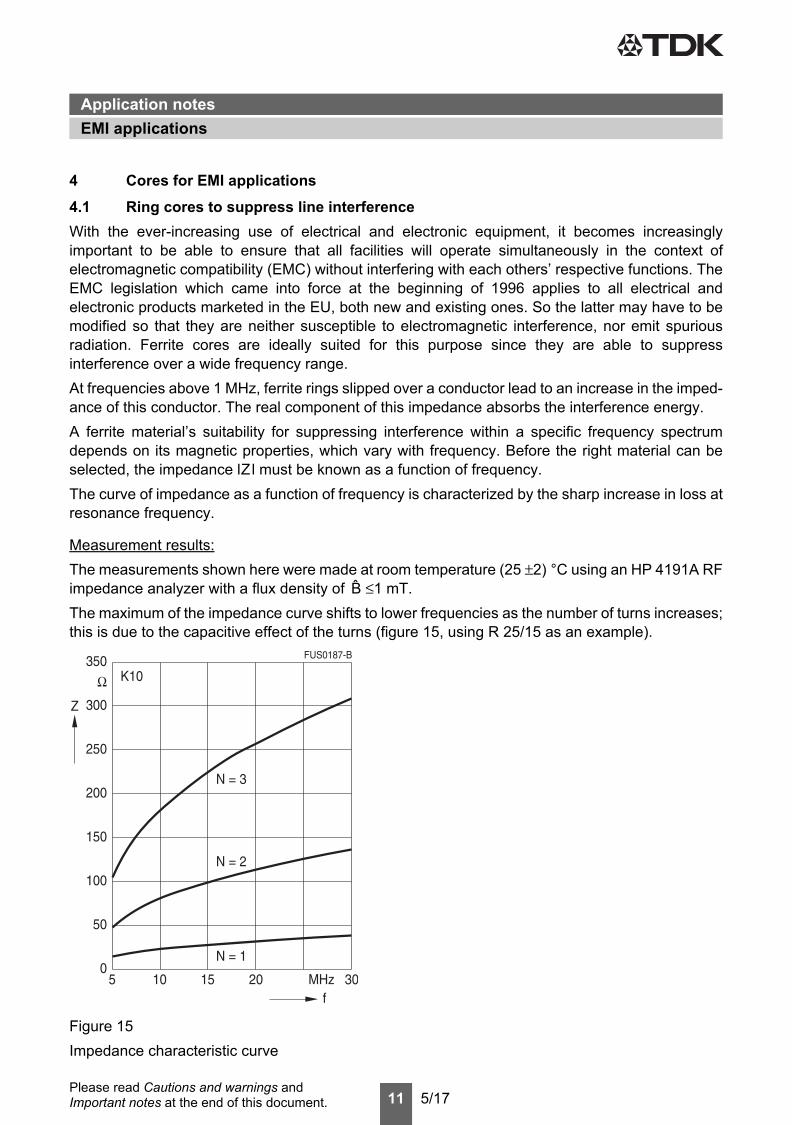
4 Cores for EMI applications4.1 Ring cores to suppress line interferenceWith the ever-increasing use of electrical and electronic equipment, it becomes increasinglyimportant to be able to ensure that all facilities will operate simultaneously in the context ofelectromagnetic compatibility (EMC) without interfering with each others’ respective functions. TheEMC legislation which came into force at the beginning of 1996 applies to all electrical andelectronic products marketed in the EU, both new and existing ones. So the latter may have to bemodified so that they are neither susceptible to electromagnetic interference, nor emit spuriousradiation. Ferrite cores are ideally suited for this purpose since they are able to suppressinterference over a wide frequency range.At frequencies above 1 MHz, ferrite rings slipped over a conductor lead to an increase in the imped-ance of this conductor. The real component of this impedance absorbs the interference energy.A ferrite material’s suitability for suppressing interference within a specific frequency spectrumdepends on its magnetic properties, which vary with frequency. Before the right material can beselected, the impedance lZl must be known as a function of frequency.The curve of impedance as a function of frequency is characterized by the sharp increase in loss atresonance frequency.
Measurement results:The measurements shown here were made at room temperature (25 ±2) °C using an HP 4191A RFimpedance analyzer with a flux density of B ≤1 mT.The maximum of the impedance curve shifts to lower frequencies as the number of turns increases;this is due to the capacitive effect of the turns (figure 15, using R 25/15 as an example).
Figure 15Impedance characteristic curve
EMI applicationsApplication notes

12 5/17Please read Cautions and warnings and Important notes at the end of this document.
The impedance curves of different materials are summarized for direct comparison. The normalizedimpedance lZ ln = lZ l / N2 x Σ (le /Ae) were used to display material properties only. The geometryfactor was calculated on the basis of the core dimensions.These normalized impedance curves are guide values, mostly measured using toroidal core R 10with a number of turns N = 1 (wire diameter 0.7 mm); they may vary slightly, depending on thegeometry.
4.2 Common-mode chokesCompact electrical and electronic equipment primarily generates common-mode interference. Inorder to be able to meet the safety requirements (keeping within the leakage current limits), chokeswith a high asymmetrically effective inductance must be used. Current-compensated chokes witha closed core topology are especially suitable for this purpose. The problem of core materialsaturation due to the useful current is solved in these designs by winding two coils with equalnumber of turns on the core. These coils are connected in such a way that the magnetic flux inducedby the upper coil is compensated by the lower coil.The new Magnetic Design Tool of EPCOS contains the normalized impedance versus frequencycurves of all ferrite materials, which are suitable for EMI applications.
Figure 16Current-compensated toroid choke; double choke shown as an example
Operating current
Line
Ferrite core
operating current
Magnetic flux inducedin core by
windings
current flowthrought
source
Disturbinginterference
disturbing interference current
Magnetic flux inducedin core by
interference
Common-mode interferencecurrent disturbing asymmetrical
SSB0554-A
EMI applicationsApplication notes

13 5/17Please read Cautions and warnings and Important notes at the end of this document.
4.3 NiZn ferritesToroidal cores of NiZn ferrites are especially suitable for the suppression of high frequency interfer-ence, because of the high ohmic resistance of these materials (ca. 105 Ωm). Therefore the negativeeffect of eddy current is negligible and the usage of these materials allow relatively high impedancevalues even at frequency well above 100 MHz. There is limiting factor to create NiZn ferrites withhigher initial permeability, because with increasing permeability the Curie temperature decreases.For example the Curie temperature for a NiZn ferrite of μi = 800 (K10) is specified >150 °C, whichis at the limit for many applications.An applicacion example in the automotive sector is the CAN bus choke, where core sizes from outerdiameter 2.5 mm to 6.3 mm (0.1 to 0.29 inch) in material K10 are used. As the transmission fre-quencies in the telecom industry are rising, it is also expected, that the demand for NiZn ferrites willgrow.Another application example for NiZn ferrite toroids is the usage of cores alone on component leadsor in board level circuitry either– to prevent any parasitic oscillations or– to attenuate unwanted signal pickup or transmissions which might travel along component leads
or interconnecting wires, traces, or cables.
4.4 MnZn ferritesFor the application as current-compensated chokes MnZn ferrites are widely used in the wholerange of sizes. The advantage of the MnZn materials is the much higher permeability, which can berealised together with a sufficiently high Curie temperature. Using very high permeability ferrites re-duces the number of turns, which are necessary to reach a certain inductance. This avoids the neg-ative impact of a high number of turns like DC resistance or parasitic capacitance and not at leastcosts.Small cores R 2.5 up to R 12.5 in the materials N30, T38, T46 can be used for example in Telecomnetworks like ISDN.Cores of mid range sizes from R 13.3 to R 26 are used as choke in power lines usually in electronicballasts in lamps, switch-mode power supplies in TV sets, washing machines and chargers. Ferritematerials: N30, T65, T35, T37, T38 and T46.The usage for core sizes R 34 and bigger are in industrial applications, in filters for frequencyconverters (lifts, pumps, traction systems, conveyer systems, air conditioning systems), general-purpose application in power electronics, UPS and wind-driven power plants. Especially for hightemperarure or/and high current application in these fields our material T65 is the most suitablebecause of its high saturation flux density of 460 mT and high Curie temperature of >160 °C. Theinitial permeability on big cores is about 4500 to 5000.If there is not especially high current or high temperature applied, we recommend to use ourmaterials N30 (μ i = 4300) and T37 (μ i approx. 5500 to 6000 on big cores). The choice of materialdepends on the frequency range, which has to be covered by the attenuation. This is determinedby the characteristic of permeability.
EMI applicationsApplication notes

14 5/17Please read Cautions and warnings and Important notes at the end of this document.
5 Cores for inductive sensorsThe proximity switch, widely used in automation engineering, is based on the damping of a high-frequency LC oscillator by the approach of a metal. The oscillator inductor consists of a cylindricalcoil and a ferrite core half whose open side forms what is known as the active area. The function ofthe ferrite core consists in spatially aligning the magnetic field so as to restrict the interaction area.The oscillator design must take into account that the inductor forms a magnetically open circuit. Theinductance and quality are decisively dependent on the coil design, unlike in the case of closedcircuits. The initial permeability plays a subordinate role here, as is shown by the following example:Core: P 9 × 5 (B65517D*)Coil: 100 turns, 0.08 CuLCurrent: 1 mAFrequency: 100 kHz
Decisive for this application is the attainment of as high a Q as possible, with the lowest possibledependence on temperature at the oscillator frequency. When the distance between the dampinglug and the active area changes, the oscillator Q should however change as strongly as possible.If the relative change in Q ΔQ/Q exceeds a predefined threshold, e.g. 10%, a switching operationis initiated at the so-called operating distance. Attainment of the target values depends on appro-priate coil dimensioning and can generally only be performed empirically.
Figure 17Inductance and quality versus initial permeabilityP 9.3 × 2.7, N = 100, f = 100 kHz, I = 1 mA
Inductive sensorsApplication notes

15 5/17Please read Cautions and warnings and Important notes at the end of this document.
6 Cores for power applications6.1 Core shapes and materialsThe enormously increased diversity of application in power electronics has led to a considerableexpansion not only in the spectrum of core shapes but also in the range of materials.To satisfy the demands of higher-frequency applications, the EFD cores have been developedin sizes EFD 10, 15, 20, 25 and EFD 30. These are characterized by an extremely flat design,optimized cross-sectional distribution and optimized winding shielding.For many standard applications up to 100 kHz, materials N27, N41 and N72 can be used. For therange up to 500 kHz, materials N92, N87, N88, N95, N96 and N97 are suitable. N49 covers the rangefrom 300 kHz to 1 MHz, PC200 to 4 MHz e.g. for DC/DC (resonance) converters.For detailed information on core shapes see the individual data sheets, for general information onmaterials see the chapter on SIFERRIT materials.
6.2 Low-profile cores for planar magneticsThe design of planar devices has attracted the attention of magnetic design engineers, since thistype of devices has interesting advantages over conventional wound components (cf. figure 18):■ Low total height■ Outstanding reproducibility of electrical parameters■ Excellent thermal performance■ High degree of integration
a) Conventional magnetics b) Planar magnetics
Figure 18Principle of conventional and planar magnetics
In order to fulfill the requirements of this technology, suitable cores are needed. The most commondesigns of low-profile cores have been adopted in the IEC standards IEC 62317-4 for RM LP coresand IEC 62317-9 for ELP, EQ and ER planar cores to offer geometrically compatible cores for thisapplication. A common denominator of these cores is that the length of the core is larger than bothits total height and its width.
Secondary
Primary
Power applicationsApplication notes

16 5/17Please read Cautions and warnings and Important notes at the end of this document.
The advantages of this core design are:■ High AL values■ High core surface to volume ratio■ Large core surface to contact heat sinkThe preferred materials used in combination with low-profile cores are N87, N88, N95, N96, N97,N92, N49 and PC200 for power applications as well as T38 and T46 for applications requiring highinductance values.
6.3 Correlation: Applications – core shape/material6.3.1 Step-down converters
Figure 19 Typical circuit diagram
Advantages■ Only one choke required■ High efficiency■ Low radio interference
Disadvantages■ Only one output voltage■ Restricted short-circuit withstand capability (no line isolation)
Application areas■ Providing a constant output voltage, isolated from input voltage■ Regulation in a forward converter■ Regulated voltage inversion■ Sinusoidal line current draw
Core/material requirements■ Standard requirements regarding losses and saturation
Power applicationsApplication notes

17 5/17Please read Cautions and warnings and Important notes at the end of this document.
EPCOS recommendations for core shape/material■ E/ETD/U/RM cores made of
N27 (standard)N87, N97 (low losses, high saturation)N88 (low losses in high temperature range)N95 (low losses in wide temperature range)N96 (low losses in low temperature range)N92 (high saturation)
6.3.2 Single-ended flyback converter
Figure 20 Typical circuit diagram
Advantages■ Simple circuit variant (low cost)■ Low component requirement■ Only one inductive component■ Low leakage losses■ Several easily regulatable output voltages
Disadvantages■ Close coupling of primary and secondary sides■ High eddy current losses in the air gap area■ Large transformer core with air gap restricts possible applications■ Average radio interference■ Exacting requirements on the components
Application areas■ Low and medium powers up to max. 200 W with wide output voltage range■ Maximum operating frequency approx. 100 kHz
Power applicationsApplication notes
18 5/17Please read Cautions and warnings and Important notes at the end of this document.
Core/material requirements■ Low power losses at high temperature■ Very high saturation with low dependence on temperature■ Gapped cores (recently also with AL value guarantee)
EPCOS recommendations for core shape/material■ E/U cores made of
N27 (standard)N87, N92, N97 (low losses, high saturation)N88 (low losses in high temperature range)N95 (low losses in wide temperature range)N96 (low losses in low temperature range)
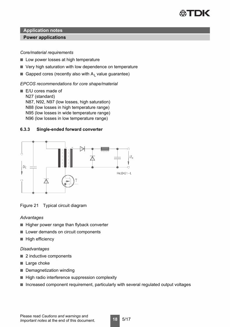
6.3.3 Single-ended forward converter
Figure 21 Typical circuit diagram
Advantages■ Higher power range than flyback converter■ Lower demands on circuit components■ High efficiency
Disadvantages■ 2 inductive components■ Large choke■ Demagnetization winding ■ High radio interference suppression complexity■ Increased component requirement, particularly with several regulated output voltages
Power applicationsApplication notes

19 5/17Please read Cautions and warnings and Important notes at the end of this document.
Application areas■ Medium and high powers (up to 500 W) especially in the area of low output voltages ■ PWM (pulse width) modulation up to approx. 500 kHz
Core/material requirements■ Low losses at high temperatures and at high frequencies (low eddy-current losses)■ Generally, ungapped cores
EPCOS recommendations for core shape/material■ E/ETD, small EFD cores, RM/PM cores made of
N27, N41 (up to 100 kHz)N87, N97 (up to 500 kHz)N49 (up to 700 kHz)PC200 (up to 4 MHz)N88 (low losses in high temperature range)
6.3.4 Push-pull converter
Figure 22 Typical circuit diagram
Advantages■ Powers up to the kW range■ Small choke■ High efficiency■ Low radio interference suppression complexity
Disadvantages■ 2 inductive components■ Complex winding■ High component requirement, particularly with several regulated output voltages
Power applicationsApplication notes

20 5/17Please read Cautions and warnings and Important notes at the end of this document.
Application areas■ High powers (»100 W), also at high output voltages■ PWM (pulse width) modulation up to 500 kHz
Core/material requirements■ Low losses at high temperatures ■ Low eddy-current losses since application areas is up to 500 kHz and above■ Generally, ungapped cores
EPCOS recommendations for core shape/material■ Large E/ETD, RM/PM cores made of
N27, N97, N87 (with large core cross sections (Ae ≥250 mm2), on account of eddy-current lossesN87 must be used even where f <100 kHz)N88 (low losses in high temperature range)N95 (low losses in wide temperature range)
6.3.5 Electronic lamp ballast device
Figure 23 Typical circuit diagram
Advantages■ Considerably reduced size compared to 50 Hz line solution■ Significantly higher efficiency than line voltage regulator
Disadvantages■ High component requirement
Application areas■ Control unit for fluorescent lamps
Fluorescent lamp
Power applicationsApplication notes

21 5/17Please read Cautions and warnings and Important notes at the end of this document.
Core/material requirements■ Low losses in the range 50 to 80 °C■ Pulse power requirements■ Gapped and ungapped E cores■ Ring cores with defined pulse characteristic
EPCOS recommendations for core shape/material■ E/ETD/EFD cores made of N72 for L1
6.4 Selection of switch-mode power supply transformer coresThe previous section (Correlation: Applications – core shape/material) provides a guide for therough selection of core shape and material.The following procedure should be followed when selecting the actual core size and material:1) Definition of requirements
– Range of power capacities Ptrans– Specification of the SMPS type– Specification of pulse frequency and maximum temperature rise– Specification of the maximum volume
2) Selection of “possible” core shapes/materials on the basis of the “Power capacity” tables startingon page 24.
These tables associate core shape/material combinations (and the volume V) with the powercapacity of the different converter types at a “typical” frequency ftyp and a “cut-off frequency” fcutoff.The typical frequency specified here is a frequency for which specific applications are known, orwhich serves as the base frequency for the specified core loss values.The cut-off frequency is selected such that the advantages of other materials predominate abovethis frequency and that it is therefore advisable to switch to a different material which is betteroptimized for this range.3) Final selection of core shape/materialThe core shapes/materials selected as possibilities under 2) must now be compared with therelevant data sheets for the specific core types and the material data (typical curves), taking thefollowing points into consideration:– Volume– Accessories (power coil former)– AL values of ungapped core– AL values/air gap specifications– Temperature minimum for losses, Curie temperature TC, saturation magnetization BS, magnetic
bias characteristic, amplitude permeability characteristicCore shape/material combinations which are not contained in the individual data sheets can berequested from EPCOS.
Power applicationsApplication notes

22 5/17Please read Cautions and warnings and Important notes at the end of this document.
6.5 Selection tables: Power capacitiesIn order to calculate the transmissible power, the following relationship is used (transformer with twoequal windings):
where C is a coefficient characterizing the converter topolgy1), i.e.C = 1: push-pull converterC = 0.71: single-ended converterC = 0.62: flyback converterBoth the core losses associated with the flux swing ΔB and the copper losses due to the currentdensity j result in a temperature increase ΔT. Assuming that both loss contributions are equal andthat Pv ~ B2 , the power capacity can be approximated by
The equation shows how the different aspects in the design contribute to the power capacity:– The material term is the performance factor PF divided by the square root of the specific core
loss level for which it was derived. For a given core shape deviations from this value are possibleas given by its data sheet.
– The values for ΔT are associated with the material according to the following table.
Material ΔTK
N27N41N49N51N72N87N88N92N95N96N97PC200
303020104050905050305020
Ptrans C ΔB fAe AN j⋅ ⋅=
1) G. Roespel, “Effect of the magnetic material on the shape and dimensions of transformers and chokes in switched-mode power supplies”, J. of Magn. and Magn. Materials 9 (1978) 145-49
Ptrans C PFPV
----------- ΔTRth--------
fCuρCu---------
AN Ae⋅lN le⋅
------------------⋅ ⋅ ⋅ ⋅≈
Material Thermaldesign
Winding Geometry
Power applicationsApplication notes

23 5/17Please read Cautions and warnings and Important notes at the end of this document.
– The thermal resistance is defined as
– These values should be regarded as typical for a given core shape. They were determined bymeasurement under the condition of free convection in air and are given in the table onpage 31 ff.For actual designs the actual values for Rth should be determined and the tabulated Ptrans values(cf. page 30 ff.) adjusted accordingly.
– The winding design was taken into account in the calcualtions by fCu = 0.4 and ρCu for DC. Inactual design large deviations of the DC resistance due to high frequency effects (skin effect,proximity effect) occur, unless special wire types such as litz wires are used. If the RAC/RDCratio for a given winding is known, this can be used to correct the tabulated power capacitiesaccordingly.
– The geometry term is related to the core shape and size. However, note that the thermalresistance is also size-dependent via the empirical relation (cf. figure 24):
The tabulated power capacities provide a means for making a selection among cores, althoughthe absolute values will not be met in practice for the reasons explained before.
In the calculation of power capacities the following conditions were also applied:– The application area for flyback converters was restricted to f <150 kHz.– The power specifications for N49 should be read as applicable to DC/DC (quasi) resonance
converters (single-ended forward operation).
RthΔT
PVcore PVcopper+----------------------------------------------=
Rth1Ve
----------∼
Power applicationsApplication notes

24 5/17Please read Cautions and warnings and Important notes at the end of this document.
– The maximum flux densities were defined as follows:For flyback converters: ΔB ≤200 mT (ΔB ≤50 mT for material N49)For push-pull converters: ΔB ≤400 mT.
Figure 24Thermal resistance versus core effective volume
Power applicationsApplication notes

25 5/17Please read Cautions and warnings and Important notes at the end of this document.
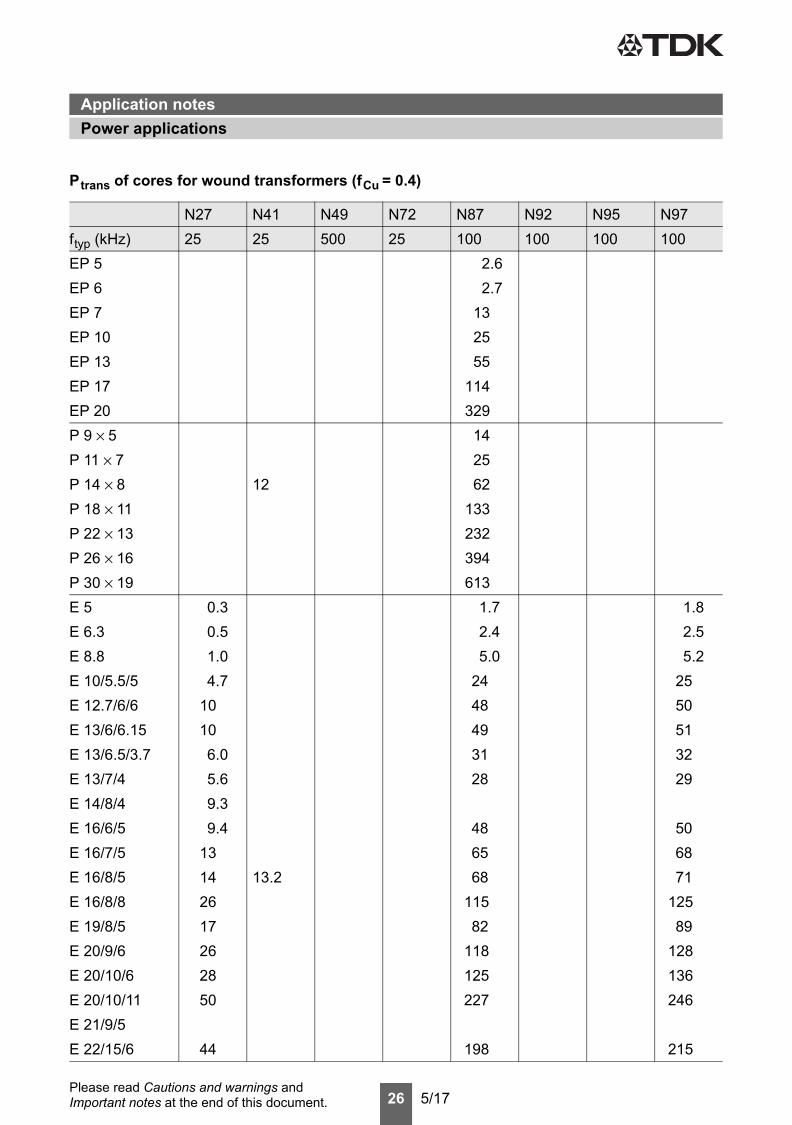
Ptrans of cores for wound transformers (fCu = 0.4)
N27 N41 N49 N72 N87 N92 N95 N97ftyp (kHz) 25 25 500 25 100 100 100 100RM 4 LP 19 20 18RM 4 22 24 31RM 5 LP 29 35 32RM 5 9 38 48 61RM 6 LP 45 56 51RM 6 17 64 79 101RM 7 LP 67 82 75RM 7 23 86 107 137RM 8 LP 97 121 111RM 8 35 131 162 207RM 10 LP 173 214 196RM 10 63 234 289 370RM 12 LP 366 453 416RM 12 136 503 622 796RM 14 LP 611 756 694RM 14 229 846 1046 1339PQ 16.11 27 47 68 39 45 77PQ 20/16 61 105 153 88 102 172PQ 20/20 74 127 185 107 123 209PQ 26/20 121 207 302 174 201 341PQ 26/25 150 256 373 215 248 420PQ 32/20 170 290 423 244 281 477PQ 32/30 256 437 636 367 424 718PQ 35/35 348 594 866 500 576 977PQ 40/30 359 613 893 515 595 1008PQ 40/40 471 804 1171 676 780 1321PQ 50/40 729 1244 1813 1046 1207 2044PQ 50/50 860 1468 2139 1234 1424 2413PM 50/39 391 1742PM 62/49 673 2999PM 74/59 1131 5036PM 87/70 1567 6982PM 114/93 2963 13196
Power applicationsApplication notes
26 5/17Please read Cautions and warnings and Important notes at the end of this document.
EP 5 2.6EP 6 2.7EP 7 13EP 10 25EP 13 55EP 17 114EP 20 329P 9 × 5 14P 11 × 7 25P 14 × 8 12 62P 18 × 11 133P 22 × 13 232P 26 × 16 394P 30 × 19 613E 5 0.3 1.7 1.8E 6.3 0.5 2.4 2.5E 8.8 1.0 5.0 5.2E 10/5.5/5 4.7 24 25E 12.7/6/6 10 48 50E 13/6/6.15 10 49 51E 13/6.5/3.7 6.0 31 32E 13/7/4 5.6 28 29E 14/8/4 9.3E 16/6/5 9.4 48 50E 16/7/5 13 65 68E 16/8/5 14 13.2 68 71E 16/8/8 26 115 125E 19/8/5 17 82 89E 20/9/6 26 118 128E 20/10/6 28 125 136E 20/10/11 50 227 246E 21/9/5E 22/15/6 44 198 215
Ptrans of cores for wound transformers (fCu = 0.4)
N27 N41 N49 N72 N87 N92 N95 N97ftyp (kHz) 25 25 500 25 100 100 100 100
Power applicationsApplication notes

27 5/17Please read Cautions and warnings and Important notes at the end of this document.
E 25/13/7 49 221 240E 25.4/10/7 43 191 208E 28/10/11 75 338 367E 30/15/7 94 421 458E 32/16/9 118 530 576E 32/16/11 132 595 647E 34/14/9 109 489 531E 36/18/11 167 751 816E 40/16/12 173 574 776 843E 42/21/15 215 968 993 1051E 42/21/20 289 1299 1332 1411E 47/20/16 304 1365 1483E 55/28/21 538 2419 2628E 55/28/25 772 3473 3772E 56/24/19 537 2414 2622E 65/32/27 1105 4971 5400E 70/33/32 1431 6439 6993E 80/38/20 1503 6761 7343E 100/60/28 2640 11890 12945EEQ 13/2.85 49 43 42 48EIQ 13/3.85 28 25 24 28EEQ 20/6.3 212 202 196 220EIQ 20/8.6 145 137 132 145EEQ 25/8 294 286 278 310EIQ 25/7.9 182 175 169 190EEQ 30/8 503 501 486 540EIQ 30/10.7 360 351 340 380ER 9.5 9ER 11/5 15 14ER 14.5/6 15 12 11 12.5ER 18/3/10 75 69 66 76EER 23/5/13 177 167 162 171 183EIR 23/7/13 111 105 101 114
Ptrans of cores for wound transformers (fCu = 0.4)
N27 N41 N49 N72 N87 N92 N95 N97ftyp (kHz) 25 25 500 25 100 100 100 100
Power applicationsApplication notes

28 5/17Please read Cautions and warnings and Important notes at the end of this document.
ER 25/6/15 247 238 230 258ER 25/9/15 155 147 143 161ER 28/17/11 290ER 32/5/21 387 381 370 412ER 35/20/11 309 1388ER 42/22/15 384 1725ER 46/17/18 376ER 49/27/17 636ER 54/18/18 482 2168ETD 29/16/10 96 428 548ETD 34/17/11 151 674 863ETD 39/20/13 230 1023 1309ETD 44/22/15 383 1708 2186ETD 49/25/16 594 2645 3385ETD 54/28/19 897 3998 5116ETD 59/31/22 1502 6692 8564EFD 10/5/3 13 12 12.5EFD 15/8/5 38 42 44EFD 20/10/7 93 115 119EFD 25/13/9 245 266EFD 30/15/9 258 319 345EV 15/9/7 29 119 135EV 25/13/13 60 248 279EV 30/16/13 142 588 664EV 36/19/16 163 678 765UI 26/22/16 120 530U 30/26/26 240 1060UI 93/104/16 1028 4600UU 93/152/16 1413 6350UI 93/104/20 1283 5750UU 93/152/20 1780 8000UI 93/104/30 1784 7950UU 93/152/30 2874 12800
Ptrans of cores for wound transformers (fCu = 0.4)
N27 N41 N49 N72 N87 N92 N95 N97ftyp (kHz) 25 25 500 25 100 100 100 100
Power applicationsApplication notes

29 5/17Please read Cautions and warnings and Important notes at the end of this document.
U 101/76/30 4400 19750UU 126/182/20 16150UI 126/119/20 10850U 141/78/30 4300 19300
Ptrans of cores for wound transformers (fCu = 0.4)
N27 N41 N49 N72 N87 N92 N95 N97ftyp (kHz) 25 25 500 25 100 100 100 100
Power applicationsApplication notes

30 5/17Please read Cautions and warnings and Important notes at the end of this document.
Ptrans of low-profile cores for planar transformers (fCu = 0.1)
N49 N87 N92 N95 N97ftyp (kHz) 500 100 100 100 100RM 4 LP 9.5 10RM 5 LP 14 17.5RM 6 LP 22 28RM 7 LP 33 41RM 8 LP 48 60RM 10 LP 86 107RM 12 LP 183 226RM 14 LP 305 378ER 9.5 4.5ER 11/5 7.5 7ER 14.5/6 13 12 11 12EILP 14 12 11 10 10EELP 14 16 17 16 18.5 16EILP 18 30 37 34 36EELP 18 44 55 50 59EILP 22 78 96 88 105EELP 22 109 134 123 146EILP 32 143 177 171 186 192EELP 32 203 252 244 261 274EILP 38 262 323 313 352EELP 38 380 470 454 510EILP 43 360 445 430 482EELP 43 500 619 599 666 672EILP 58 731EELP 58 1046EILP 64 800 991EELP 64 1130 1397
Power applicationsApplication notes

31 5/17Please read Cautions and warnings and Important notes at the end of this document.
6.6 Thermal resistance for the main power transformer core shapes
Core shapes Rth (K/W) Core shapes Rth (K/W) Core shapes Rth (K/W)RM 4 120 P 30 × 19 22 EI LP 32 26RM 4 LP 135 P 36 × 22 17 EI LP 64 9.5RM 5 100 E 5 313 EE LP 64 9RM 5 LP 111 E 6.3 284 EE LP 32 24RM 6 80 E 8.8 204 EI LP 38 20RM 6 LP 90 E 10/5.5/5 106 EE LP 38 18RM 7 68 E 12.7/6/6 75 EI LP 43 16RM 7 LP 78 E 13/6/6.15 79 EE LP 43 15RM 8 57 E 13/6.5/3.7 91 EI LP 58 12RM 8 LP 65 E 13/7/4 94 EE LP 58 11RM 10 40 E 14/8/4 79 ER 9.5 164RM 10 LP 45 E 16/6/5 76 ER 11/5 134RM 12 25 E 16/7/5 69 ER 14.5/6 99RM 12 LP 29 E 16/8/5 65 ER 28/17/11 22RM 14 18 E 16/8/8 49 ER 35/20/11 18RM 14 LP 21 E 19/8/5 60 ER 42/22/15 14PQ 16/11.6 77 E 20/9/6 49 ER 46/17/18 13PQ 20/16 51 E 20/10/6 46 ER 49/27/17 9PQ 20/20 46 E 20/10/11 34 ER 54/18/18 11PQ 26/20 32 E 21/9/5 59 ETD 29/16/10 28PQ 26/25 29 E 22/15/6 38 ETD 34/17/11 20PQ 32/20 27 E 25/13/7 40 ETD 39/20/13 16PQ 32/30 22 E 25.4/10/7 41 ETD 44/22/15 11PQ 35/35 19 E 28/10/11 28 ETD 49/25/16 8PQ 40/30 19 E 30/15/7 23 ETD 54/28/19 6PQ 40/40 16 E 32/16/9 22 ETD 59/31/22 4PQ 50/40 12 E 32/16/11 21 EFD 10/5/3 120PQ 50/50 11 E 34/14/9 23 EFD 15/8/5 75PM 50/39 15 E 36/18/11 18 EFD 20/10/7 45PM 62/49 12 E 40/16/12 20 EFD 25/13/9 30PM 74/59 9.5 E 42/21/15 19 EFD 30/15/9 25PM 87/70 8 E 42/21/20 15 EV 15/9/7 55PM 114/93 6 E 47/20/16 13 EV 25/13/13 27EP 5 329 E 55/28/21 11 EV 30/16/13 21EP 6 318 E 55/28/25 8 EV 36/19/16 16EP 7 141 E 56/24/19 9.5 U26/22/16 21EP 10 122 E 65/32/27 6.5 U30/26/26 13EP 13 82 E 70/33/32 5.5 UU 93/152/16 4.5EP 17 58 E 80/38/20 7 UI 93/104/16 5EP 20 32 E 100/60/28 4 UU 93/152/20 4P 9 × 5 142 EI LP 14 116 UI 93/104/20 4.5P 11 × 7 106 EE LP 14 105 UU 93/152/30 3P 14 × 8 73 EI LP 22 38 UI 93/104/30 4P 26 × 16 27 EE LP 22 35 U 101/76/30 3.3P 18 × 11 51 EI LP 18 61 U 141/78/30 2.5P 22 × 13 37 EE LP 18 56
Power applicationsApplication notes

32 5/17Please read Cautions and warnings and Important notes at the end of this document.
The following applies to all products named in this publication:
1. Some parts of this publication contain statements about the suitability of our products forcertain areas of application. These statements are based on our knowledge of typical require-ments that are often placed on our products in the areas of application concerned. We never-theless expressly point out that such statements cannot be regarded as binding statementsabout the suitability of our products for a particular customer application. As a rule, EP-COS is either unfamiliar with individual customer applications or less familiar with them than thecustomers themselves. For these reasons, it is always ultimately incumbent on the customer tocheck and decide whether an EPCOS product with the properties described in the product spec-ification is suitable for use in a particular customer application.
2. We also point out that in individual cases, a malfunction of electronic components or fail-ure before the end of their usual service life cannot be completely ruled out in the currentstate of the art, even if they are operated as specified. In customer applications requiring avery high level of operational safety and especially in customer applications in which the mal-function or failure of an electronic component could endanger human life or health (e.g. in acci-dent prevention or life-saving systems), it must therefore be ensured by means of suitable de-sign of the customer application or other action taken by the customer (e.g. installation of pro-tective circuitry or redundancy) that no injury or damage is sustained by third parties in the eventof malfunction or failure of an electronic component.
3. The warnings, cautions and product-specific notes must be observed.
4. In order to satisfy certain technical requirements, some of the products described in this pub-lication may contain substances subject to restrictions in certain jurisdictions (e.g. be-cause they are classed as hazardous). Useful information on this will be found in our MaterialData Sheets on the Internet (www.epcos.com/material). Should you have any more detailedquestions, please contact our sales offices.
5. We constantly strive to improve our products. Consequently, the products described in thispublication may change from time to time. The same is true of the corresponding productspecifications. Please check therefore to what extent product descriptions and specificationscontained in this publication are still applicable before or when you place an order.
We also reserve the right to discontinue production and delivery of products. Consequent-ly, we cannot guarantee that all products named in this publication will always be available. Theaforementioned does not apply in the case of individual agreements deviating from the foregoingfor customer-specific products.
6. Unless otherwise agreed in individual contracts, all orders are subject to the current versionof the “General Terms of Delivery for Products and Services in the Electrical Industry”published by the German Electrical and Electronics Industry Association (ZVEI).
7. The trade names EPCOS, CeraCharge, CeraDiode, CeraLink, CeraPad, CeraPlas, CSMP,CTVS, DeltaCap, DigiSiMic, ExoCore, FilterCap, FormFit, LeaXield, MiniBlue, MiniCell, MKD,MKK, MotorCap, PCC, PhaseCap, PhaseCube, PhaseMod, PhiCap, PowerHap, PQSine,PQvar, SIFERRIT, SIFI, SIKOREL, SilverCap, SIMDAD, SiMic, SIMID, SineFormer, SIOV,ThermoFuse, WindCap are trademarks registered or pending in Europe and in othercountries. Further information will be found on the Internet at www.epcos.com/trademarks.
Important notes

33 5/17Please read Cautions and warnings and Important notes at the end of this document.
Symbol Meaning Unit
AAeALAL1AminANARBΔBB ΔB BDCBRBSC0CDFDFdEaffcutofffmaxfminfrfCugHH HDCHchh/μi 2
IIDCIJkk3k3cL
Cross section of coilEffective magnetic cross sectionInductance factor; AL = L/N2
Minimum inductance at defined high saturation ( μa)Minimum core cross sectionWinding cross sectionResistance factor; AR = RCu/N2
RMS value of magnetic flux densityFlux density deviationPeak value of magnetic flux densityPeak value of flux density deviationDC magnetic flux densityRemanent flux densitySaturation magnetizationWinding capacitanceCore distortion factorRelative disaccommodation coefficient DF = d/μiDisaccommodation coefficientActivation energyFrequencyCut-off frequencyUpper frequency limitLower frequency limitResonance frequencyCopper filling factorAir gapRMS value of magnetic field strengthPeak value of magnetic field strengthDC field strengthCoercive field strengthHysteresis coefficient of materialRelative hysteresis coefficientRMS value of currentDirect currentPeak value of currentPolarizationBoltzmann constantThird harmonic distortionCircuit third harmonic distortionInductance
mm2
mm2
nHnHmm2
mm2
μΩ = 10–6 ΩVs/m2, mTVs/m2, mTVs/m2, mTVs/m2, mTVs/m2, mTVs/m2, mTVs/m2, mTF = As/Vmm–4.5
Js–1, Hzs–1, Hzs–1, Hzs–1, Hzs–1, Hz
mmA/mA/mA/mA/m10–6 cm/A10–6 cm/AAAAVs/m2
J/K
H = Vs/A
Symbols and termsFerrites and accessories
Symbols and terms

34 5/17Please read Cautions and warnings and Important notes at the end of this document.
Symbol Meaning Unit
ΔL/LL0LHLpLrevLslelNNPCuPtransPVPFQRRCuRhΔRhRiRpRsRthRVsTΔTTCttvtan δtan δLtan δrtan δetan δhtan δ/μiUÛVeZZn
Relative inductance changeInductance of coil without coreMain inductanceParallel inductanceReversible inductanceSeries inductanceEffective magnetic path lengthAverage length of turnNumber of turnsCopper (winding) lossesTransferrable powerRelative core lossesPerformance factorQuality factor (Q = ωL/Rs = 1/tan δL)ResistanceCopper (winding) resistance (f = 0)Hysteresis loss resistance of a coreRh changeInternal resistanceParallel loss resistance of a coreSeries loss resistance of a coreThermal resistanceEffective loss resistance of a coreTotal air gapTemperatureTemperature differenceCurie temperatureTimePulse duty factorLoss factorLoss factor of coil(Residual) loss factor at H → 0Relative loss factorHysteresis loss factorRelative loss factor of material at H → 0RMS value of voltagePeak value of voltageEffective magnetic volumeComplex impedanceNormalized impedance |Z|n = |Z| /N2 × ε (le/Ae)
HHHHHHmmmm
WWmW/g
ΩΩΩΩΩΩΩK/WΩmm°CK°Cs
VVmm3
ΩΩ/mm
Symbols and termsFerrites and accessories

35 5/17Please read Cautions and warnings and Important notes at the end of this document.
All dimensions are given in mm.
Surface-mount device
Symbol Meaning Unit
ααFαeεrΦηηBηiλsμμ0μaμappμeμiμp'μp"μrμrevμs'μs"μtot
ρΣl/AτCuω
Temperature coefficient (TK)Relative temperature coefficient of materialTemperature coefficient of effective permeabilityRelative permittivityMagnetic fluxEfficiency of a transformerHysteresis material constantHysteresis core constantMagnetostriction at saturation magnetizationRelative complex permeabilityMagnetic field constantRelative amplitude permeabilityRelative apparent permeabilityRelative effective permeabilityRelative initial permeabilityRelative real (inductive) component of μ (for parallel components)Relative imaginary (loss) component of μ (for parallel components)Relative permeabilityRelative reversible permeabilityRelative real (inductive) component of μ (for series components)Relative imaginary (loss) component of μ (for series components)Relative total permeabilityderived from the static magnetization curveResistivityMagnetic form factorDC time constant τCu = L/RCu = AL/ARAngular frequency; ω = 2 Πf
1/K1/K1/K
Vs
mT-1
A–1H–1/2
Vs/Am
Ωm–1
mm–1
ss–1
Symbols and termsFerrites and accessories

36 5/17Please read Cautions and warnings and Important notes at the end of this document.
Mechanical stress and mountingFerrite cores have to meet mechanical requirements during assembling and for a growing numberof applications. Since ferrites are ceramic materials one has to be aware of the special behaviorunder mechanical load.As valid for any ceramic material, ferrite cores are brittle and sensitive to any shock, fast tempera-ture changing or tensile load. Especially high cooling rates under ultrasonic cleaning and high staticor cyclic loads can cause cracks or failure of the ferrite cores.For detailed information see data book, chapter “General - Definitions, 8.1”.
Effects of core combination on AL value Stresses in the core affect not only the mechanical but also the magnetic properties. It is apparentthat the initial permeability is dependent on the stress state of the core. The higher the stresses arein the core, the lower is the value for the initial permeability. Thus the embedding medium shouldhave the greatest possible elasticity.For detailed information see data book, chapter “General - Definitions, 8.1”.
Heating upFerrites can run hot during operation at higher flux densities and higher frequencies.
NiZn-materials The magnetic properties of NiZn-materials can change irreversible in high magnetic fields.
Ferrite AccessoriesEPCOS ferrite accessories have been designed and evaluated only in combination with EPCOSferrite cores. EPCOS explicitly points out that EPCOS ferrite accessories or EPCOS ferrite coresmay not be compatible with those of other manufacturers. Any such combination requires prior te-sting by the customer and will be at the customer‘s own risk.EPCOS assumes no warranty or reliability for the combination of EPCOS ferrite accessories withcores and other accessories from any other manufacturer.
Processing remarksThe start of the winding process should be soft. Else the flanges may be destroyed.– Too strong winding forces may blast the flanges or squeeze the tube that the cores can not be
mounted any more.– Too long soldering time at high temperature (>300 °C) may effect coplanarity or pin arrange-
ment.– Not following the processing notes for soldering of the J-leg terminals may cause solderability
problems at the transformer because of pollution with Sn oxyde of the tin bath or burned insula-tion of the wire. For detailed information see chapter “Processing notes”, section 2.2.
– The dimensions of the hole arrangement have fixed values and should be understood asa recommendation for drilling the printed circuit board. For dimensioning the pins, the groupof holes can only be seen under certain conditions, as they fit into the given hole arrangement.To avoid problems when mounting the transformer, the manufacturing tolerances for positioning the customers’ drilling process must be considered by increasing the hole diameter.
Cautions and warningsFerrites and accessories
Cautions and warnings

37 5/17Please read Cautions and warnings and Important notes at the end of this document.
Ferrites and accessories
Display of ordering codes for EPCOS productsThe ordering code for one and the same product can be represented differently in data sheets, data books, other publications and the website of EPCOS, or in order-related documents such asshipping notes, order confirmations and product labels. The varying representations of the ordering codes are due to different processes employed and do not affect the specifications of the respective products. Detailed information can be found on the Internet under www.epcos.com/orderingcodes.
Cautions and warnings