fermilab ilc school, july 07 1 ilc global control system john carwardine, anl
TRANSCRIPT

Fermilab ILC School, July 07 1
ILC Global Control System
John Carwardine, ANL
Fermilab ILC School, July 07 2
ILC Accelerator overview
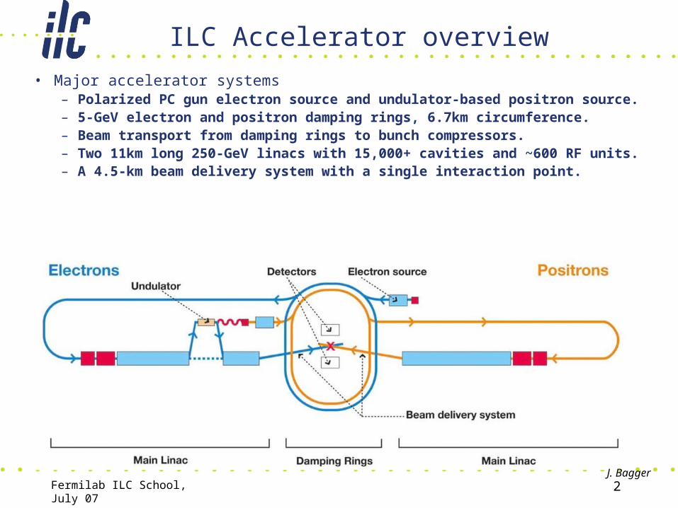
• Major accelerator systems– Polarized PC gun electron source and undulator-based positron source.– 5-GeV electron and positron damping rings, 6.7km circumference.– Beam transport from damping rings to bunch compressors.– Two 11km long 250-GeV linacs with 15,000+ cavities and ~600 RF units.– A 4.5-km beam delivery system with a single interaction point.
J. Bagger
Fermilab ILC School, July 07 3
Control System Requirements and Challenges
• General requirements are largely similar to those of any large-scale experimental physic machines …but there are some challenges
• Scalability– 100,000 devices, several million control points.– Large geographic scale: 31km end to end– Multi-region, multi-lab development team.
• Support ILC accelerator availability goals of 85%.– Intrinsic Control system availability of 99% by design.
• Cannot rely on approach of ‘fix in place.’• May require 99.999% (five nines) availability from each crate.
– Functionality to help minimize overall accelerator downtime.
Fermilab ILC School, July 07 4
Requirements and Challenges …(2)
• Precision timing & synchronization– Distribute precision timing and RF phase references to many
technical systems throughout the accelerator complex.– Requirements consistent with LLRF requirements of 0.1%
amplitude and 0.1 degree phase stability.
• Support remote operations / remote access (GAN / GDN)– Allow collaborators to participate with machine
commissioning, operation, optimization, and troubleshooting.– At technical equipment level there is little difference between
on-site and off-site access - Control Room is already ‘remote.’– There are both technical and sociological challenges.

Fermilab ILC School, July 07 5
Requirements and Challenges …(3)
• Extensive reliance on machine automation– Manage accelerator operations of the many accelerator
systems, eg 15,000+ cavities, 600+ RF units.– Automate machine startup, cavity conditioning, tuning,
etc.
• Extensive reliance on beam-based feedback– Multiple beam based feedback loops at 5Hz, eg
• Trajectory control, orbit control• Dispersion measurement & control• Beam energies• Emittance correction
Fermilab ILC School, July 07 6
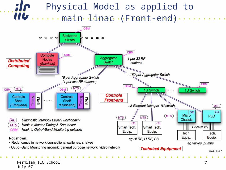
Control System Functional Model
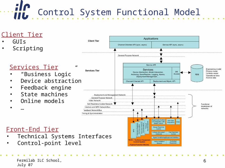
Client Tier• GUIs• Scripting
Services Tier• “Business Logic”• Device abstraction• Feedback engine• State machines• Online models• …
Front-End Tier• Technical Systems Interfaces• Control-point level
Fermilab ILC School, July 07 7
Physical Model as applied to main linac (Front-end)
Fermilab ILC School, July 07 8
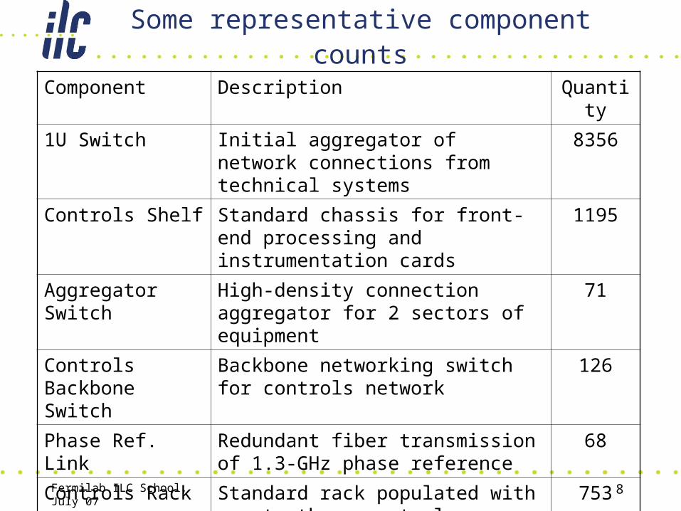
Some representative component counts
Component Description Quantity
1U Switch Initial aggregator of network connections from technical systems
8356
Controls Shelf Standard chassis for front-end processing and instrumentation cards
1195
Aggregator Switch High-density connection aggregator for 2 sectors of equipment
71
Controls Backbone Switch
Backbone networking switch for controls network
126
Phase Ref. Link Redundant fiber transmission of 1.3-GHz phase reference
68
Controls Rack Standard rack populated with one to three controls shelves
753
LLRF Station Two racks per station for signal processing and motor/piezo drives
668
Fermilab ILC School, July 07 9
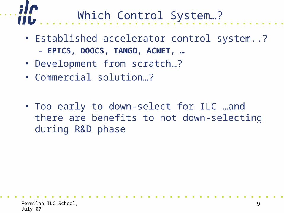
Which Control System…?
• Established accelerator control system..?– EPICS, DOOCS, TANGO, ACNET, …
• Development from scratch…?• Commercial solution…?
• Too early to down-select for ILC …and there are benefits to not down-selecting during R&D phase
Fermilab ILC School, July 07 10
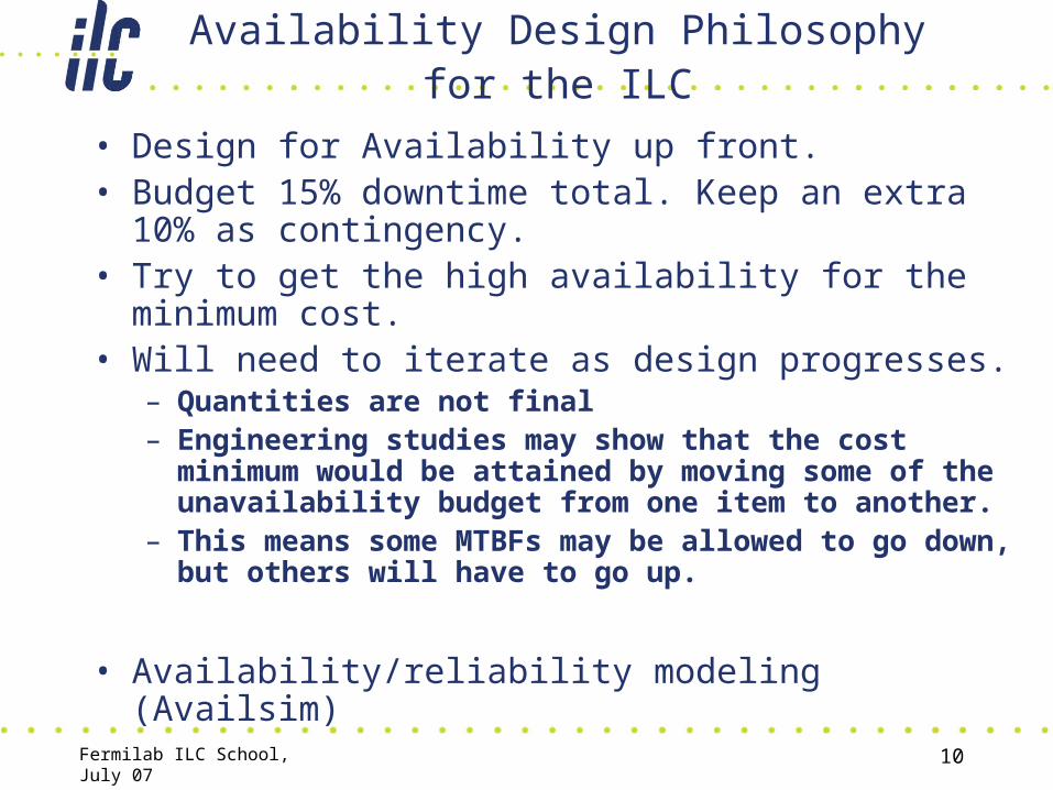
Availability Design Philosophy for the ILC
• Design for Availability up front.• Budget 15% downtime total. Keep an extra 10% as
contingency.• Try to get the high availability for the minimum cost.• Will need to iterate as design progresses.
– Quantities are not final– Engineering studies may show that the cost minimum
would be attained by moving some of the unavailability budget from one item to another.
– This means some MTBFs may be allowed to go down, but others will have to go up.
• Availability/reliability modeling (Availsim)
Fermilab ILC School, July 07 11
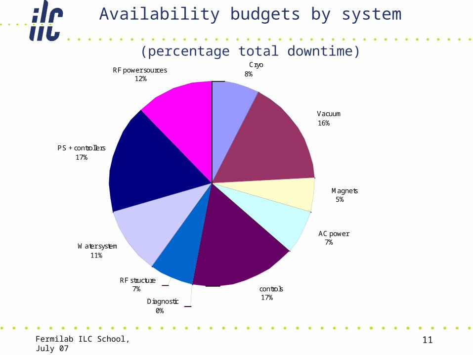
Availability budgets by system
(percentage total downtime) Cryo
8%
Vacuum16%
Magnets5%
AC power7%
controls17% Diagnostic
0%
RF structure7%
Water system11%
PS + controllers17%
RF power sources12%

MTBF/MTTR requirements from Availsim
Device
Improvement factor
A that gives 17%
downtime for 2
tunnel undulator e+ source
Downtime (%) due
to these devices for 2 tunnel undulator
e+ source with strong keep_alive
Nominal MTBF (hours)
Nominal
MTTR (hours)
magnets - water cooled 20 0.4 1,000,000 8power supply controllers 10 0.6 100,000 1
flow switches 10 0.5 250,000 1water instrumention near pump 10 0.2 30,000 2
power supplies 5 0.2 200,000 2kicker pulser 5 0.3 100,000 2
coupler interlock sensors 5 0.2 1,000,000 1collimators and beam stoppers 5 0.3 100,000 8
all electronics modules 3 1.0 100,000 1AC breakers < 500 kW 0.8 360,000 2
vacuum valve controllers 1.1 190,000 2regional MPS system 1.1 5,000 1
power supply - corrector 0.9 400,000 1vacuum valves 0.8 1,000,000 4
water pumps 0.4 120,000 4modulator 0.4 50,000 4
klystron - linac 0.8 40,000 8coupler interlock electronics 0.4 1,000,000 1
vacuum pumps 0.9 10,000,000 4controls backbone 0.8 300,000 1

Fermilab ILC School, July 07 13
High Availability primer
• Availability A = MTBF/(MTBF+MTTR)– MTBF=Mean Time Before Failure– MTTR= Mean Time To Repair– If MTBF approaches infinity A approaches 1– If MTTR approaches zero A approaches 1– Both are impossible on a unit basis– Both are possible on a system basis.
• Key features for HA, i.e. A approaching 1:– Modular design– Built-in 1/n redundancy– Hot standby systems– Hot-swap capable at subsystem unit or subunit level
Fermilab ILC School, July 07 14
Systems That Never Shut Down
• Any large telecom system will have a few redundant Shelves, so loss of a whole unit does not bring down system – like RF system in the Linac.– Load auto-rerouted to hot spare, again like Linac.
• Key: All equipment always accessible for hot swap.• Other Features:
– Open System Non-Proprietary – very important for non-Telecom customers like ILC.
– Developed by industry consortium¹ of major companies sharing in $100B market.
– 20X larger market than any of old standards including VME leads to competitive prices.
¹ PICMG -- PCI Industrial Computer Manufacturer’s Group
Fermilab ILC School, July 07 15
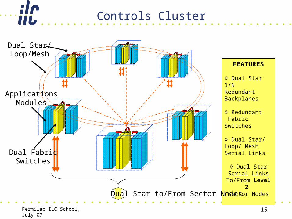
Controls Cluster
FEATURES
◊ Dual Star 1/NRedundant Backplanes
◊ Redundant Fabric Switches
◊ Dual Star/ Loop/ Mesh Serial Links
◊ Dual Star Serial Links To/From
Level 2 Sector Nodes
Dual Star to/From Sector Nodes
Dual FabricSwitches
ApplicationsModules
Dual Star/Loop/Mesh

Fermilab ILC School, July 07 16
HA Concept DR Kicker Systems
• Approx 50 unit drivers• n/N Redundancy
System level (extra kickers)
• n/N Redundancy Unit level (extra cards)
• Diagnostics on each card, networked, local wireless

Fermilab ILC School, July 07 17
Physical Model as applied to main linac (Front-end)
Fermilab ILC School, July 07 18
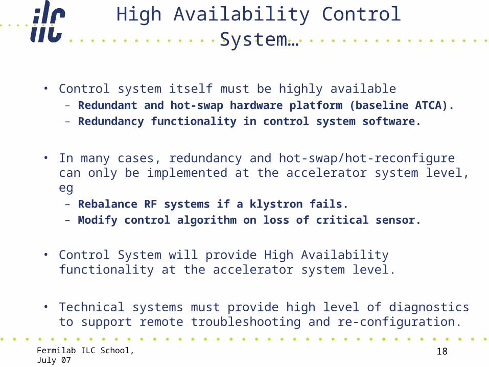
High Availability Control System…
• Control system itself must be highly available– Redundant and hot-swap hardware platform (baseline ATCA).
– Redundancy functionality in control system software.
• In many cases, redundancy and hot-swap/hot-reconfigure can only be implemented at the accelerator system level, eg– Rebalance RF systems if a klystron fails.
– Modify control algorithm on loss of critical sensor.
• Control System will provide High Availability functionality at the accelerator system level.
• Technical systems must provide high level of diagnostics to support remote troubleshooting and re-configuration.

Fermilab ILC School, July 07 19
5-Slot Crate w/ Shelf Manager Fabric Switch Dual IOC Processors
Rear View
16 Slot Dual Star Backplane
4 Hot-Swappable
Fans
Shelf Manager
Dual IOC’sFabric Switch
Dual 48VDC Power Interface
ATCA as a reference platform…
R. Larsen

Fermilab ILC School, July 07 20

Fermilab ILC School, July 07 21
ATCA as reference platform for Front-end electronics
• Representative of the breadth of high-availability functions needed– Hot-swappable components: circuit boards, fans, power
supplies, …– Remote power management: power on/off each circuit
board– Supports redundancy: processors, comms links, power
supplies,…– Remote resource management through Shelf Manager
• µTCA offers lower cost but with reduced feature set.• There is growing interest in the physics community in exploring
ATCA for instrumentation and DAQ applications.
• As candidate technology for the ILC, ATCA/µTCA have strong potential …currently is it an emerging standard.
Fermilab ILC School, July 07 22
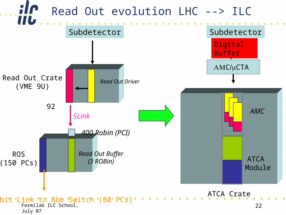
Read Out evolution LHC --> ILC
Subdetector
Read Out Crate(VME 9U)
Read Out Driver
Read Out Buffer(3 ROBin)
ROS(150 PCs)
Gbit Link to Gbe Switch (60 PCs)
92SLink
Subdetector
400 Robin (PCI)
AMC
ATCA Module
ATCA Crate
Digital Buffer
CCTA
Fermilab ILC School, July 07 23
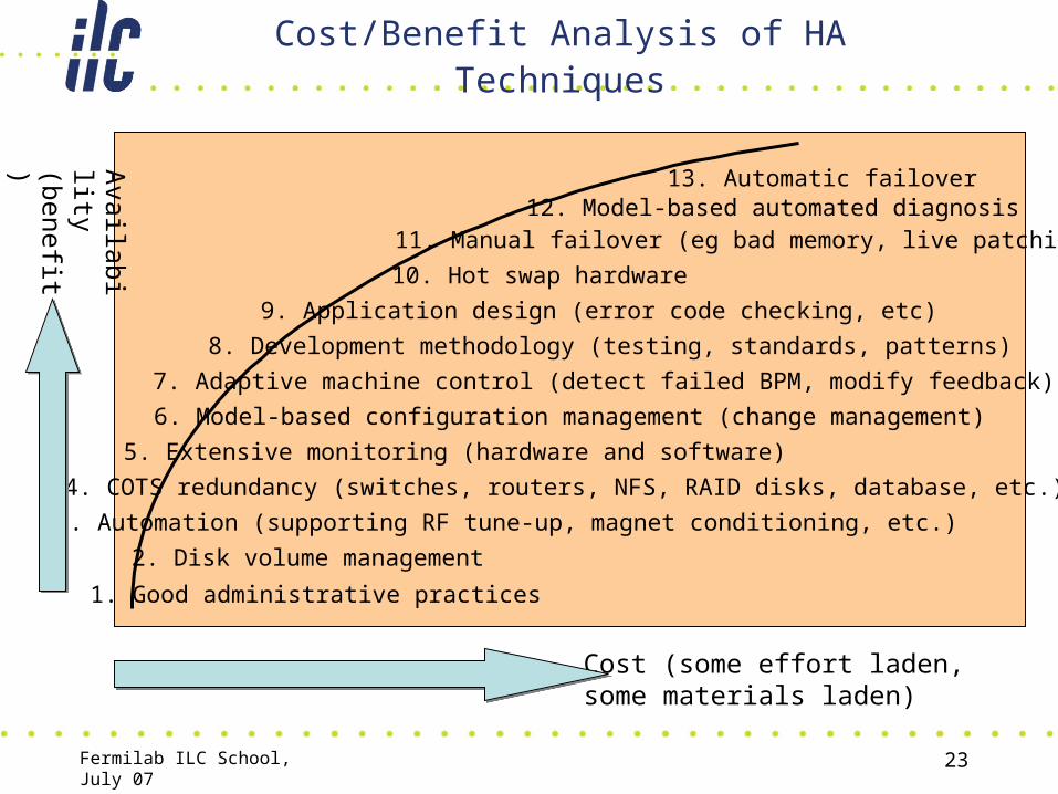
Cost/Benefit Analysis of HA Techniques
Cost (some effort laden,some materials laden)
Availability
(benefit)
1. Good administrative practices
2. Disk volume management
3. Automation (supporting RF tune-up, magnet conditioning, etc.)
4. COTS redundancy (switches, routers, NFS, RAID disks, database, etc.)
5. Extensive monitoring (hardware and software)
6. Model-based configuration management (change management)
7. Adaptive machine control (detect failed BPM, modify feedback)
8. Development methodology (testing, standards, patterns)
9. Application design (error code checking, etc)
10. Hot swap hardware
11. Manual failover (eg bad memory, live patching)12. Model-based automated diagnosis
13. Automatic failover

Fermilab ILC School, July 07 24
HA R&D objectives
• Learn about HA (High Availability) in context of accelerator controls– Bring in expertise (RTES, training, NASA, military, …)
• Develop (adopt) a methodology for examining control system failures– Fault tree analysis– FMEA or scenario-based FMEA– Supporting software (CAFTA, SAPPHIRE, …)– Others?
• Develop policies for detecting and managing identified failure modes– Development and testing methodology– Workaround– Redundancy
• Develop a full “vertical” prototype implementation– Ie. how we might implement above policies
• Integrate portions of “vertical” prototype with test stands (LLRF)• Feed some software-oriented data to SLAC availability simulation?

Fermilab ILC School, July 07 25
•Configuration Management•Infrastructure Monitoring •Software Runtime Lifecycle Management•Shelf Management•Automation
•Software QA•Development Methodology•Conflict Avoidance
High Availability Software
• What are the most common and critical failure modes in control system software?
•Mis-configuration
•Network buffer overruns
•Application logic bugs
•Task deadlock
•Accepting conflicting commands
•Ungraceful handling of failed sensors/actuators
•Flying blind (lack of monitoring)
•Introduction of untested features
•More…
• How do we mitigate these, and what is the cost/benefit?
Availability = MTBF
MTBF + MTTR
Fermilab ILC School, July 07 26
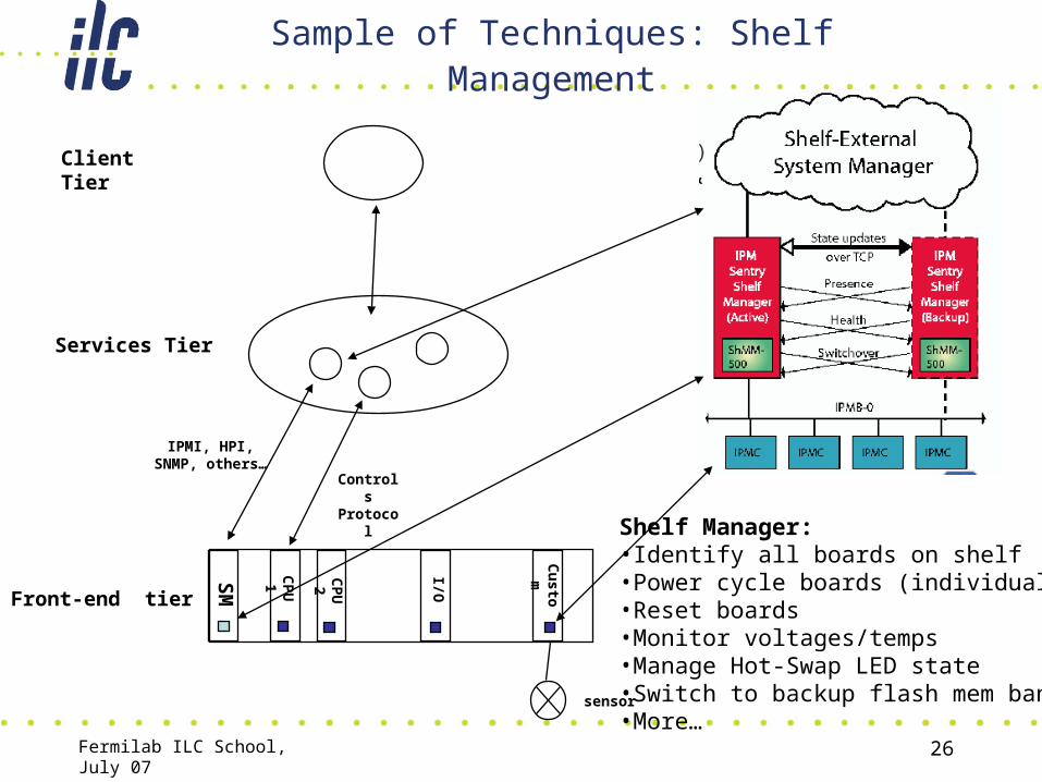
Sample of Techniques: Shelf Management
CP
U1
CP
U2 I/O
Cu
stom
Services Tier
IPMI, HPI, SNMP, others…
Controls Protocol
Client Tier
Front-end tier
SM
sensor
Shelf Manager:•Identify all boards on shelf•Power cycle boards (individually)•Reset boards•Monitor voltages/temps•Manage Hot-Swap LED state•Switch to backup flash mem bank•More…

Fermilab ILC School, July 07 27
SAF – Availability Management Framework
Shutting downLocked-Instantiation
Unlocked Locked
AMF Logical Entities Service Unit Administrative States
Service Unit
Component
Component
Node U
Service Unit
Component
Component
Node V ServiceGroup
ServiceInstance
Service Instanceis work assignedto Service Unit
active standby1. Service unit starts out un-instantiated.
2. State changed to locked, meaning software is instantiated on node, but not assigned work.
3. State changed to unlocked, meaning softwareis assigned work (Service Instance).
A simple example of software component runtime lifecycle management
Fermilab ILC School, July 07 28
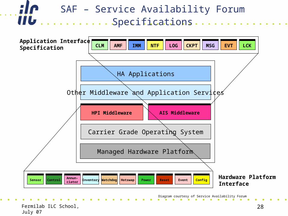
SAF – Service Availability Forum Specifications
Managed Hardware Platform
Carrier Grade Operating System
HPI Middleware AIS Middleware
Other Middleware and Application Services
HA Applications
AMFCLM IMM CKPTLOGNTF LCKEVTMSG
ControlSensorAnnun-ciator
HotswapWatchdogInventory EventResetPower Config
Diagram courtesy of Service Availability Forum
Hardware PlatformInterface
Application InterfaceSpecification
Fermilab ILC School, July 07 29
SAF – Availability Management Framework
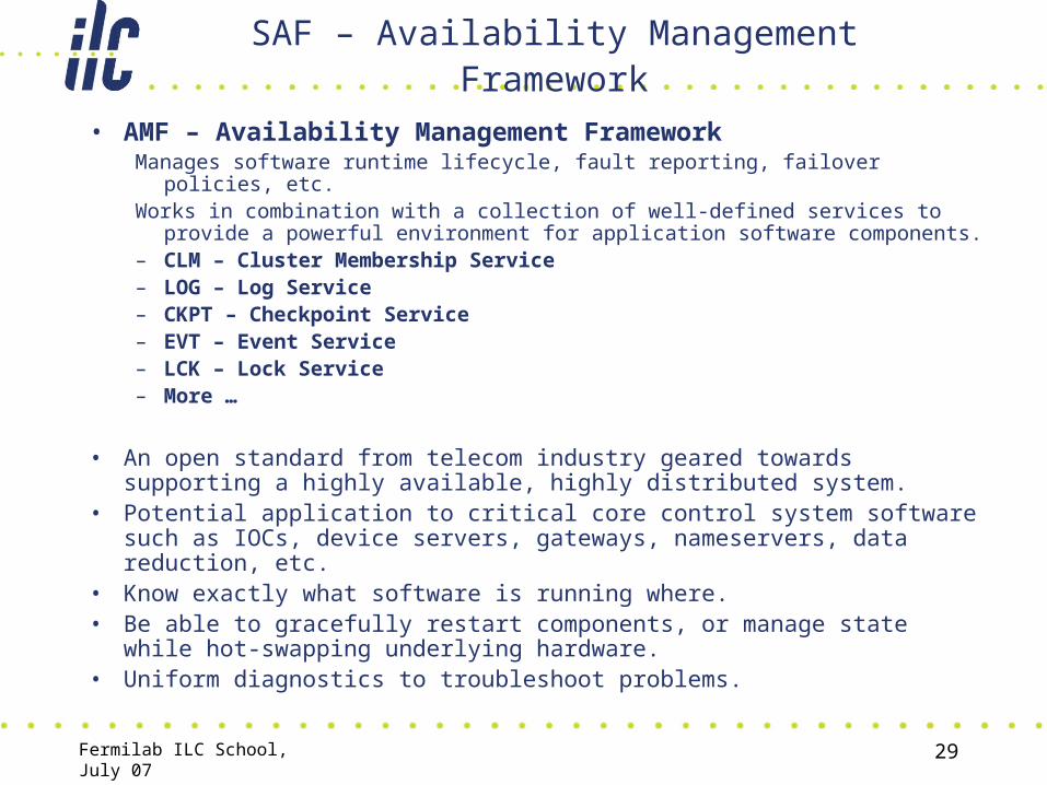
• AMF – Availability Management FrameworkManages software runtime lifecycle, fault reporting, failover policies, etc.Works in combination with a collection of well-defined services to provide a
powerful environment for application software components.– CLM – Cluster Membership Service– LOG – Log Service– CKPT – Checkpoint Service– EVT – Event Service– LCK – Lock Service– More …
• An open standard from telecom industry geared towards supporting a highly available, highly distributed system.
• Potential application to critical core control system software such as IOCs, device servers, gateways, nameservers, data reduction, etc.
• Know exactly what software is running where.• Be able to gracefully restart components, or manage state while hot-
swapping underlying hardware.• Uniform diagnostics to troubleshoot problems.

Fermilab ILC School, July 07 30
An HA software framework is just the start…
– SAF (Service Availability Forum) implementations won’t “solve” HA problem
• You still have to determine what you want to do and encode it in the framework – this is where work lies
1.What are failures
2.How to identify failure
3.How to compensate (failover, adaptation, hot-swap)– Is resultant software complexity manageable?
• Potential fix worse than the problem• Always evaluate: “am I actually improving availability?”

Fermilab ILC School, July 07 31
R&D Engineering Design (EDR) Phase
• Main focus of R&D efforts are on high availability– Gain experience with high availability tools & techniques to
be able to make value-based judgments of cost versus benefit.
• Four broad categories– Control system failure mode analysis– High-availability electronics platforms (ATCA)– High-availability integrated control systems
• Conflict avoidance & failover, model-based resource monitoring.
– Control System as a tool for implementing system-level HA• Fault detection methods, failure modes & effects
Fermilab ILC School, July 07 32
HA means doing things differently…
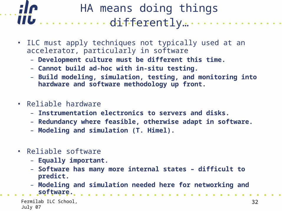
• ILC must apply techniques not typically used at an accelerator, particularly in software– Development culture must be different this time.– Cannot build ad-hoc with in-situ testing.– Build modeling, simulation, testing, and monitoring into hardware
and software methodology up front.
• Reliable hardware– Instrumentation electronics to servers and disks.– Redundancy where feasible, otherwise adapt in software.– Modeling and simulation (T. Himel).
• Reliable software– Equally important.– Software has many more internal states – difficult to predict.– Modeling and simulation needed here for networking and software.

Fermilab ILC School, July 07 33
Controls topic areas
• LLRF algorithms• RF phase & timing distribution, synchronization• Machine automation, beam-based feedback• ATCA evaluation as front-end instrumentation platform• ATCA evaluation for control system integration• HA integrated control system• Integrated Control System as a tool for system-level HA• Remote access, remote operations (GAN/GDN)• Failure modes analysis
• Lot’s of opportunities to get involved…