ferc pre filing draft (pdf)
TRANSCRIPT

Jnofflclal FERC-Generated PDF of 20070703-0242 Received by FERC OSEC 06/29/2007 in Docket#: PF07-9-000
$mlmm lat~, ~ 5~00 VCm&e~mee Co~ Hoesk~, TX 77056
877.379.0338 kgl ~,e
pt.JSLIO June 29, 2007
Ms. Kimber]y D. Bose, Secretary Federal Energy Regulatory Commission 888 First Street N.E.
STECKMAN $ RIDGE
ORIG/NAL (..." , ~3 ... ~
Washington, D.C. 20426 t-.-
Re: Steckman Ridge, LP Project, Docket No. PF07-9, OEP/DG2E/G~2 ~ -4c~rr~ Draft Resource Report Nos. 1 and 10 and Stakeholder List ¢ ' , ~"nC~
"0 Dear Ms. Bose: ~.ci~ 67. rn
On June 1, 2007, the Director of the Office of Energy Projects i~ued a letter to Stockman Ridge, LP ("Stec.kman' 3 in the referenced docket approving Steckman's request to commence the Federal Energy Regulatory Commission's ("FERC" or "commission") pro-filing process for conducting the National Environmental Policy Act review of Steckman's Project. Pursuant to Section 157.21(0(4)-(5) of the Commission's regulations Stockman hereby submits for filing with the Commission draft Resource Report Nos. I and 10 and the stakeholder mailing listJ
An original plus seven copies of the draft Resource Reports, without certain figures designated as "Non-Internct Public" ("NIP") information, and the stakeholder mailing list, without privileged landowner information are included herewith. An original plus seven copies of the NIP information are included and marked "Non-lutemet Public." Information that is considered NIP may be made available in the Commission's Public Reference Room, but should not be posted on the public intemet. An original only of the privileged landowner information is included and marked "Privileged and Confidential. "2 Privileged information should be treated as confidential and is for use by Commission Staff only and not to be released to the public. In addition, Stockman has included stakeholder mailing labels for Commission Staffuse.
Should you have any questions regarding this filing, please contact me at (713) 627-5415 or Julie Allison at (713) 627-4144.
Respect~ly submitted,
Garth Johnson D/rector, Certificates and Reporting Stockman Ridge, LP
Enclosures
e_.~: Doug Sipe (FERC) Magdalene Manco (FERC)
~18 C.F.R. § 157.21(0(4)-(5)(2007). 2 18 C.F.R. §§ 380.12, 388.112 (2007).
www.~lckmo n rido~oco~.com PUBLIC

Jnofficial FERC-Generated PDF of 20070703-0242 Received by FERC OSEC 06/29/2007 in Docket#: PF07-9-000 1
ill.=:
.._EiZ~ , .::: OF THE
Z0~] JU~12q I D b:3b
.. ::,- .:,l ui~Y CO: ,i.~ISSIr-;t;
STECKMAN RIDGE
Steckman Ridge Storage Project
Bedford County, Pennsylvania
Pre-Filing Draft - Resource Report 1
Pre-Filing Draft - Resource Report 10
Stakeholder Contact List
FERC Docket No. PF07-9
June 29, 2007

Jnofflclal FERC-Generated PDF of 20070703-0242 Received by FERC OSEC 06/29/2007 in Docket#: PF07-9-000
v
STECr N
STECKMAN RIDGE STORAGE PROJECT
W
RESOURCE REPORT 1 General Project Description
PRELIMINARY D R A F T - June 29, 2007
W

Jnofflclal FERC-Generated PDF of 20070703-0242 Received by FERC OSEC 06/29/2007 in Docket#: PF07-9-000
STE-CI 4 RIDGE PRELIMINARY DRAFT- June 29, 2007
RESOURCE REPORT I-GENERAL PROJECT DESCRIPTION
[]
Filing Requirement
Provide a detailed description and location map of the Project facilities. (§380.12(cXI))
Location In Enviremental Report
Section 1.3, Figure 1.3-1 and Appendix IA
[] Describe any non-jurisdictional facilities that would be built in Section 1.12 association with the Project (§380.12(c) (2))
[] Provide current original U.S. Geological Sunley (USGS) 7.5- Appendix 1A located in minute series topographic maps with mileposts showing the Vol. II-B Project facilities. (§380.12(cX3)).
r'l Provide aerial images or photographs or alignment sheets Appendix IA located in based on these sources with mileposts showing the Project Vol. 11-13 facilities. (§380.12(¢)(3)).
[] Provide plot/site plans of compressor stations showing the Figure 9.3-1 location of the nearest noise-sensitive areas (NSA) within in Resource Report 9 I mile. (§380.12(c)(3,4)).
[] Descn'be consmu~on and restoration methods. (§380.12(c) Section 1.5 (6)).
[] Identify the permits required for constnt~on tgross surface Table 1.10-1 waters. (§3S0.12(c)(9)).
[] Provide the names and addresses of all affected lsndowne~ and certify that all affected landowners would be notified as required in §157.6(d). (§§380.12(aX4) and (cXI0)).
Appendix I D located in Volume II-D
V
RR I - General Project Description i Steclonan Ridge Storage Project

Jnofflclal FERC-Generated PDF of 20070703-0242 Received by FERC OSEC 06/29/2007 in Docket#: PF07-9-000
V
v
S TECKMAN RIDGE
TABLE OF CONTENTS
PRELIMINAR Y DRAFT- June 29, 2007
1.0 R E S O U R C E R E P O R T 1 - G E N E R A L P R O J E C T D E S C R I P T I O N .................................... i -1
I. I INTROIXJCT1ON .......................................................................................................................................... 1-1 1.1.1 Parpose and Need ................................................................................................................................. I-1
1.2 ENVIRONMENTAL REPORT ORGANIZATION ............................................................................................... 1-2 1.2.1 Maps and Drawings ............................................................................................................................. 1-2
] .3 LOCATION AND D e s c ~ OF PROJECT FACILITIES .............................................................................. 1-5 1.3.1 Storage Wells ........................................................................................................................................ 1-6 1.3.2 Storage F ie ld Piping Network .............................................................................................................. 1-6 1.3.3 CompressOr Station .............................................................................................................................. 1-8 1.3.4 Access Roads ........................................................................................................................................ 1-9 1.3.5 Ware Yards and Pipe Yards .................................................................................................................. 1-9
1.4 LAND REQUIgEMENTS ............................................................................................................................. 1-I0
1.4.1 Storage Wells ...................................................................................................................................... 1-11 1.4.2 Storage Fie ld Piping Network ............................................................................................................ 1-12
1.4.2. I Trunk Lines ................................................................................................................................................ 1 -! 3 1.4.2.2 Well Laterals .............................................................................................................................................. 1-13 1.4.2.3 SFPN A b o ~ Facilities ................................................................................................................... 1 -I 3 1.4..2.4 A d d ~ Tempoct~ Wofkspace ............................................................................................................ I - 13
1.4.3 Compressor Station ............................................................................................................................ 1-14 1.4.4 Access Roads ...................................................................................................................................... 1-14 1.4.5 Ware Y a r d s a n d P i p e Yards ................................................................................................................ 1-14
1.5 CONSTRUCTION AND RESTORATION METHODS ....................................................................................... 1-16 1.5.1 Storage Wells ...................................................................................................................................... 1-16 1.5.2 Storage Fie ld Piping Network ............................................................................................................ 1-16
| .5.2.1 SUmdsrd Comlruction and Ralomtion Methods ...................................................................................... 1- ! 6 1.5.2.2 Water t~ly ~ Methods ............................................................................................................. 1-19 1.5.2.3 Wetland ~ o n Methods .................................................................................................................. 1-22 1.5.2.4 Rugged Topography ................................................................................................................................. 1-23 1.5.2.5 Residential A~eas ....................................................................................................................................... 1-23 1.5.2.6 Horizontal Dim~omd DriIK~8 ................................................................................................................. 1-23 1.5.2.7 Agficultmul lamd .................................................................................................................................. 1-23 1.5.2.8 R ~ d Crossings. ..................................................................................................................................... 1-26 1.5.2.9 Rock Removal ~ d B lmia8 ....................................................................................................................... 1-28
1.5.3 Compressor Stathm ........................................................................................................................... 1-28 1.5.4 Other Aboveground Facllities ............................................................................................................ 1-29 1.5.5 H y d ~ x ~ l t c Te.gting ............................................................................................................................ 1-29 1.5.6 ~ r o n m e n t a l 7kainlr~for Construction .......................................................................................... 1-30
1.6 CONSTRUCTION SCHEDULE AND WORK FORCE ....................................................................................... | -30 1.7 OPERATlg~ AND MAINTENANCE ............................................................................................................. 1-3 | 1.8 FUTURE FI. ,A~ AND ~ D O N M E N T ...................................................................................................... 1-31
1.9 AGENCY CONgULTA'r/oN AND LAND OWNER NOTIFICATION .................................................................. 1-32 1.9.1 Agency Comndtation and Coordination ............................................................................................. 1-32 1.9.2 Public Particlpaffon and Outreach .................................................................................................... 1-32 1.9.3 Landowner Names and Addresses ...................................................................................................... 1-32
I.I0 PERMITS AND API~OVALS ....................................................................................................................... 1-33
l.ll STATUS O~ FIELD SURVEYS ..................................................................................................................... 1-33
I.I 2 NON-JuRLSDICrlONAL FACIUTIES ........................................................................................................... 1-33
RR I - General Project Description ii Stecloffo~ Ridge Storage Project

Jnofflclal FERC-Generated PDF of 20070703-0242 Received by FERC OSEC 06/29/2007 in Docket#: PF07-9-000
STECKMAN (~ RIDGE PRELIMINARY DRAFT- June 29, 2007
LIST OF TABLES
TABLE 1.3-1 STECKMAN RIDGE STORAGE PROJECT- PROPOSED FACILITIES ........................................................... I-5 TABLE 1.3-2 PROPOSED PERMANENT ACCESS ROADS FOR THE STECKMAN RIDGE STORAGE PROJECT . . . . . . . . . . . . . . . . . I - I 0 TABLE 1.4-1 LAND REQUIREMENTS FOR ABOVEGROt~D FACILITIES .................................................................... I-I I TABLE 1.4-2 LAND REQUIREMENTS FOR THE SFPN ............................................................................................... I - 12 TABLE 1.5-1 AGRICULTURAL LANDS AFFECTED BY THE PROJECT [To BE CONFIRMED] ........................................ 1-24 TABLE 1.5-2 ROADS CROSSED BY THE STORAGE FIELD PIPING NETWORK ............................................................ 1-27 TABLE 1.6-1 PRELIMINARY CONSTRL~CnON SCHEDULE ........................................................................................ 1-30 TABLE I. 10-1 PERMIT AND CONSULTATION LIST FOR THE STECKMAN RIDGE STORAGE PROJECT ......................... !-34
LIST OF FIGURES
FIGURE 1.1-1. PROJECT LOCATION MAP .................................................................................................................... 1-3 FIGURE | . | -2. PROJECT FACILITIES OVERVIEW MAP ................................................................................................. I--4 FIGURE 1.5-|. TYPICAL WELL CONSTRUCTION SITE ................................................................................................ l- 15
W
APPENDICES
Appendix IA - Project Drawings and Maps (located in Volumes II-B and II-C)
Volume II-B (Nowlntemet Public} 1. Steckman Ridge Storage Facility Aerial Plan (Scale I-inch = 500 feet) 2. Storage FactOry Piping Network Alignment Sheets (Scale 1 -inch = 200 feet) 3. Full Size USGS Quadraask Map 4. i I "x 17" USGS Quadrangle Map 5. Typical SFPN ROW Configuration. 6. National Wetland Inventory (NWI) Map
Volume II-C (CEIl Informadon~ 7. Compressor Station Plot Plan 8. M&R Station Plot Plan 9. Other Aboveground Facility D r a w i n g s
Appendix IB - Sleclonan Erosion and Sedimenlation Control Plan
Appendix IC - Spill Prevention ~ 1 and Countermeasure (SPCC) Plan
Appendix ID - Project Line List o f Affi:cted Landowners, Sample Landowner Letter and Abutters within ~ Mile of Proposed Compressor Station (Privileged and Confidential - see Volmne 11-1))
Appendix ! E - Agency CorreslXnaknce and Contact List
V
RR! - C~.era/Project Descr~o~n ~il 5~ec/a~an R~e Storage Project
Jnofflclal FERC-Generated PDF of 20070703-0242 Received by FERC OSEC 06/29/2007 in Docket#: PF07-9-000
SIECKh d'4 RIDGE PRELIMINARY D R A F T - June 29, 2007
V
V
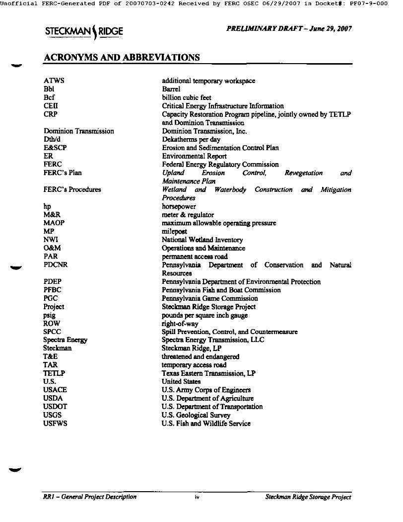
ACRONYMS AND ABBREVIATIONS
ATWS Bbl Bcf CEll CRP
Dominion Transmission Dth/d E&SCP ER FERC FERC's Plan
FERC's Procedures
hp M&R MAOP NIP NWI O&M PAR PDCNR
PDEP PFBC PGC Project psig ROW SPCC Spe a Steclanan T&E TAR TETLP U.S. USACE USDA USDOT USGS USFWS
additional temporary workspace Barrel billion cubic feet Critical Energy Infrastructure Information Capacity Restoration Program pipeline, jointly owned by TETLP and Dominion Tmnmmission Dominion Transmission, Inc. Dekatherms per day Erosion and Sedimentation Control Plan Environmental Report Federal Energy Regulatory Commission Upland Erosion Control, Re~getation and Maintenance Plan Wetland and Waterbody Construction and Mitigation Procedures horsepower meter & regulator maximum allowable operating pressure milepost National Wetland Inventory Opemiom and Maimenance permanent accen road Pennsylvania Department of Conservation and Natural Resources Pennsylvania Depa~en t of Environmental Protection Pennsylvania Fish and Boat Commission Pennsylvania Came Commission Stockman Ridge Storage Project pounds per square inch gauge right-of-way Spill Prevention, ConU'ol, and Countermeasure Spcclza Energy Transmission, LLC Steelaram Ridge, LP threatened and endangered temporary access road Texas Eastern Transmission, LP United States U.S. Army Corps of Enginccrs U.S. Department of Agriculture U.S. Department of Trans~rtafion U.S. Geological Sm-vcy U.S. Fish and Wildlife Service
V
RR I - General Project Description iv Steclonan Ridge Storage Project

Jnofflclal FERC-Generated PDF of 20070703-0242 Received by FERC OSEC 06/29/2007 in Docket#: PF07-9-000
PRE-FILING D R A F T - June 29, 2007
v
v
1.0 R E S O U R C E R E P O R T 1 - G E N E R A L P R O J E C T D E S C R I P T I O N
1.1 Introduction
Steckman Ridge, LP (Steckmaa) is applying ",o the Federal Energy Regulatory Commission (FERC or the Commission) for a Certificate of Public Convenience and Necessity under Section 7(c) ofthe Natural Gas Act, 15 U.S.C. §717f(b) and §717f(c) to convert a recently acquired depleted natural gas production field located in Bedford County, Pennsylvania into a multi-cycle natural gas storage facility. This proposed facility will have approximately 17.7 billion cubic feet (Bcf) oftotsl capacity, of which up to 12 Bcf will be working capacity and 5.7 Bcf will be base gas. The proposed Steckman Ridge Storage Project (the Project) will include:
• the removal and/or abandonment of existing production field pip'rag and abovegrouad equipment; • the conversion of five depleted production wells into storage wells; • the drilling and development of 18 new storage wells and construction ofastmciated abovegronnd
well head facilities; • construction of a Storage Field Piping Network (SFPN) and associated abovegrouud facilities
including launcher/receiver facilities and valve sites; and • construction ofone 9,000 horsepower 0tp) compressor station including a meter and regulator
(M&R) station, common launcher and receiver facility, and other associated appurtenances.
Consu'uction of the Project is planned to start in early June 2008 with an in-service date by April 2009; however, interim services could potentially be available in late 2008.
Steckman is a joint venture limited partnership owned in equal interests by subsidiaries of Spectra Energy Transmission, LLC (Spectra Energy) and New Jersey Resources Corporation. Stecknmn acquired the depleted natural gas production field from Pennsylvania General Energy, LLC (PGE) in 2007. The production field acquired by Steckman was discovered and developed in 2002 by PGE and has produced approximately 12.3 Bcf of natural gas from an estimated reservoir capacity of 17.7 Bcf. The PGE facilities acquired by Stecknmn include five depleted production wells, approximately 2.8-miles of gathering line% an M&R station, and mineral and storage rights. Figure 1.1-1 shows the location of the proposed Project and Figure 1.1-2 shows the proposed Project facilities.
1.1.1 Purpose and Need
Since about the 1930% natural gas storage has played an important role in balancing the complexities of supply and demand in the Unitml States (U.S.), especially throughout the Northeast and Mid-Atlantic Regions. This is largely due to the seasonal usage profile of the region. The supply and demand dynamics of the Northeast and Mid-Atlantic Regions are on the verge of a significant transition, creating a substantial increase in the demand for storage services in these regions. The growth in liquefied natural gas (loNG) supply along the eastern seaboard and the introduction of incremental supply from the Rocky Mountain Region are important new sources of natural gas that will meet the growing demands for natural gas in the Northenst and Mid-Atlantic Regions. Growth in conventional markets will continue to expand the seasonal peak requirements while growing gas fired power generation markets have introduced a summer peak to the market profile. Consequently, there is an increasing demand for natural gas storage services that will offer growing markets the ability to manage price volatility along with providing supply security, diversity, flexibility and seasonal balancing.
In response to strong market demand for natural gas storage services, Stecknmn acquired PGE's depleted natural gas production field and proposes to convert the depleted field into a multi-cycle natural gas storage facility that will provide secure and flexible storage services to the Northeast and Mid-Atlantic
RRI - General Project Description 1-1 Steckman Ridge Storage Project

Jnofflclal FERC-Generated PDF of 20070703-0242 Received by FERC OSEC 06/29/2007 in Docket#: PF07-9-000
PRE-FILING D R A F T - June 29, 2007
v
V
v
Regions by April 2009. In May - June 2007, Steckman Ridge held an open season to determine market interest. Steckman Ridge received approximately 60 Bcf in non-binding interest for storage services starting in April 2009. Given its strategic location between new natural gas supplies from the east and mid-west, and its close proximity to markets served by existing interstate gas pipelines owned by Texas Eastern Transmission, LP (TETLP) and Dominion Transmission, Inc. (Dominion Transmission) the Project will become an integral part of the Northeast and Mid-Atlantic's energy future, allowing it to serve key customers, including various local distribution companies (LDCs), power generators, and marketers. The Project will also serve as an emergency supply to replace lost production during outages caused by weather events, such as hurricanes.
1.2 Environmental Report Organization
This Environmental Report if, R) is composed of 13 separate Resource Reports and has been prepared in accordance with FERC Order No. 603 et seo. and Parts 157 and 380 of FERC's regulations, which governs the filing of applications for Certificates of Public Convenience and Necessity authorizing the construction and operation of facilities to provide service under Section 7 of the Natural Gas AcL Stecknum's application and accompanying ER have been organized into separate volumes, in compliance with FERC's document control requireng~ts for Public, Non-Intemet Public (NIP), Privileged & Confidential, and Critical Energy Infrastructure Information (CEIl) classes of information. The contents of each volume are outlined below.
Volume I
• Volume I-A: Application and all Public exhibits (excluding Exhibits F-l, G, G-I, and G-2); • Volume I-B: All NIP exhibits to the Application (excluding Exhibits F-l, G, G-I, and G-2); • Volume I-C: Exhibits G, G-l, and G-2 (CEH information); • Volume I-D: Privileged and Confidential
Volume II (Exhibit F-l)
• Volume H-A: Environmental Repom excluding NIP information; • Volume II-B: NIP information from the Environmental Reports; • Voktrne H-C: CEII information included in the ER - Facility Plot Plans; • Volume II-D: Land Owner List and Cultural Rasc~'ces Information (Privileged & Confidential)
1.2.1 Maps and lkawlap
Appendix 1A (bound separately in Volumes l i b and H-C) includes drawings and maps for all proposed Project facilities referenced in Resource Report 1. Volume II-B contains l inch = 200 feet scale aerial photo-based alignment sheets that incorporate civil and environmental survey data and depict the proposed well sites and SFPN, including consm~on workspace, existing pipelines, approximate property boundaries, waterbodies (including streams, drainages and ponds) and wetlands within constru~on workapace, aboveground facilities, access roads, and public roads. Volume H-B also contains National Wetland Inventory (NWl) maps, 1:24,000 scale full-size United States Geological Service (USGS) 7.5 minute series topographic quadrangle maps as well as 8.5 x I l-inch USGS 7.5 minute series topographic quadrangle excerpts showing the proposed Project facilities. Typical drawings for the storage well sites and plot plans for the compressor station and M&R station are bound separately in Volume II-C. Also included in Volume II-C are drawings for the other proposed aboveground facilities including valve sites and pig launcher and receiver facilities.
RR I - General Project Description 1-2 Steclonan Ridge Storage Project

Jnofflclal FERC-Generated PDF of 20070703-0242 Received by FERC OSEC 06/29/2007 in Docket#: PF07-9-000
PRE-FILING D R A F T - June 29, 2007
V
Figure 1.1-1. Project Location Map
Non-Internet Public (Included under separate cover)
v
RRI - General Project Descrlption I-3 S t ~ Ridge Storage Project

Jnofflclal FERC-Generated PDF of 20070703-0242 Received by FERC OSEC 06/29/2007 in Docket#: PF07-9-000
PRE-FILING DRAFT- June 29, 2007
v
Figure 1.1-2. Project Facilities Overv/ewMap
Nou-Interaet Publk (Included under separate cover)
V
V
RR I - General Project Description I-4 Steclonan Ridge Storage P r o j e c t

Jnofflclal FERC-Generated PDF of 20070703-0242 Received by FERC OSEC 06/29/2007 in Docket#: PF07-9-000
PIlE-FILING DRAFT-Jun~ 29, 2007
v
1.3 Location and Description of Project FacUlties
The proposed Project is located in Bedford County, Pennsylvania, which is situated in the mmh-cenlxaJ potion of the Southern Alleghenies region. The proposed storage facility area lies within the Township of Monroe and is approximately seven to ten miles southwest of the intersection of Interstate-70 and Interstate-76 (the Pennsylvania Turnpike). The primary public roads providing access to the Project area include Rock Hill Church Road (Slate Road [SR] 2029), Big Creek Road (SR 2007), Clark Road, Jay Road, and Mearlde Road. Table 1.3-I and the following sections identify and describe the proposed Project facilities.
v
v
TABLE 1.3-1
s u o . - . - R k l ~ S~onq~ P.qect - Propo*ed Padmks
F ~ J ~ Name i ~ t o s
• ~ v m 5 pmduclAon ~ l l s (W¢Ih~ # 1 - ~ ) Io s /ora~ v,,'~ls; • I~ill and deve .~ 18 ~ stors~e wefl8 (WelhJ ~ - W23); • .4.~de bed m d miniver, a~ l
• Methlnol/¢hem/~tl injection f~cilitim: • C e c ~ k i ~ m e a a m m ~ t (EGIvl) e q ~ and • 2 t im~man~m s c u m n~ld~ ( I0 exisl/ng and I l new) and imuking m
Sto~gt Fidd rc~g N ~ r k fSFPN) • Tnmk lane 91 - 16-inch dtamet~, gglxm¢imately 3.13 miles king; • Tnmk Line 90 - 16-im:h diameter, ~ 4+36 mik* l ing; and • 23 Well Lamrals - 6-~cb, ~ and l 0:inch d~tmcseG appmx~Uely 3.6 mileu ~ml
• ~ v e r at mminm of I.iae 9 I; • L m m c h e ~ m ~ v ~ al Icem~us of Lira: 90; • 9 /ml lN IDill v a i ~ w m (I 8 v a ; ~ ) ; ~md • Tm~k I~'~ t H Vl]~elL
Cm~w~s~ ~
• " I~o ¢emp, nmor l ~ l m p ; • One c a m m ~ ImikltnS;
• One s~m'qpe Imikfing;
• In~, / f l l la ' • S ~ m bk~vdown rock.:
• ( ] w h e a t e n ; • D d ~ l m a ~ e ~ e m • Gas cea~m. • m , ll c ami~ . • G m , x l l~a+e Stmam; • mm+-l~ <~mmmm, • +two m t l l ~ a l l~ id l ( l c u l ~ l lxl I ~ ) ; • One c o - l o c a ~ c o u ~ [mmchar aacl rcceiv~ u l e m b l y for I ~ c 91 ,rod L ~ : 90; *ad • One co-kxated M&R Mafioa.
T ~ W~ hwd dmd ~ Ymu'
• ODecoeu~wam~.
RR I - General Project Description !-5 Stecbnan Ridge Storage Project
Jnofflclal FERC-Generated PDF of 20070703-0242 Received by FERC OSEC 06/29/2007 in Docket#: PF07-9-000
PRE-FILING D R A F T - June 29, 2007
V
v
1.3.1 Storage Wells
As shown in Table 1.3-1, Steckmnn proposes to convert five production wells into storage wells (Wells #1 through #5) and develop an additional 18 new storage wells (Wells #6 through #23). Each of the 23 well sites will have ahovegronnd facilities including metering equipment complete with inlet and outlet isolation valves, EGM equipment to control and measure volumes of gas into and out of each well, and a methanol injection pump skid. Nine of the proposed wells will also have Argus pig valves installed. The well sites will have a parking area and will be accessed by a permanent access road. In most cases power will be supplied to each well site within the 25-foot standard permanent access road easement.
1.3.2 Storage Field Piping Network
As stated in Table 1.3-1, Steckman proposes to transport natural gas between each of the storage wells and the proposed compressor station through a SFPN that will include two, 16-inch diameter trunk lines (Lines 90 and 91) and twenty-three 6-inch, 8-inch, and 10-inch diameter well laterals (Table 1.3-1). The well laterals will connect to the trunk lines either independently or in small groups. The total pipe length of the SFPN is approximately I I.I miles.
Steckman determined that the existing production pipeline system is inadequate for the flow rates and operating pressures associated with the operation of the proposed Project. As such, where new facilities will be installed, the existing production system will be removed or abandoned as part of the construction of the Project. The following section describes the proposed SFPN components including aboveground facilities.
Steckman ~ to construct two separate 16-inch diameter trunk lines (Line 91 and Line 90) to move gas between the compressor station and the well laterals.
rru Ll O/
Line 91 will be approximately 3.13 miles in length with approximately 2.3 miles (73 percent) of the line following the ex'u~'ing production pipeline right-of-way (ROW). Line 91 starts within the proposed 43- acre compressor station (MP 0.0) property and heads to the south in parallel with Line 90 for a l ~ l y 1,230 feet before deviating to the southwest and heading down to the crossing of Rock Hill Church Read at IMP 0.37. Upon exifin 8 the station property at MP 0.31, Line 91 will be located within new ROW up to MP 0.47 where it will start to co-locate with the existing pipeline ROW within an open field and head to the southwest. Steckman routed the first 0.47 miles of Line 91 within new ROW to avoid stream and we0and crossings along Rock Hill Church Road that would have been necessary if the existing ROW was utilized.
Moving uphill, Line 91 connects to the lateral line for Well #6 (Line 91A) along the edge of the field at MP 0.55. Continuing to the southwest within the existing ROW, Line 91 connects with the lateral line (Line 91B) for Well #7 on a wooded hill top (IMP 0.86) and then heads back downhill to the lateral line connection (Line 91C) with Well #3 within an open field. Line 91 continues along the existing ROW to the south across open hillside, connecting with the lateral line (Line 91D) for Well #8 at MP 1.24 in an area of shrube and trees. At MP 1.31, Line 91 connec~ to the lateral line (Line 91E) for Well #9 within a wooded area and then enters a cultivated field approximately 35 feet to the south. At MP 1.42, Line 91 changes direction within the field and heads to the southwest crossing a large fenced-in enclosure for white-tailed deer from MP 1.57 to MP 1.66. This entire segment of Line 91 ROW utilizes the existing pipeline ROW.
RR I - General Project Description 1-6 Steclonon Ridge Storage Project

Jnofflclal FERC-Generated PDF of 20070703-0242 Received by FERC OSEC 06/29/2007 in Docket#: PF07-9-000
PRE-FILING D R A F T - June 29. 2007
v
V
Upon exiting the deer enclosure, Line 91 makes a direction change to the south within a cultivated field and starts to deviate from the existing ROW at MP 1.74 to make the connection with the lateral line for Well #10 (Line 9IF) at MP 1.89. Moving downslope within new ROW, Line 91 crosses Big Creek Road at MP 1.96 approximately 80-feet to the north of the existing ROW pipeline crossing of Big Creek Road. Line 91 immediately crosses a tributary stream to West Branch Sideling Hill Creek at MP 1.98. In this area, Steckman routed Line 91 to the west of the existing ROW to minimize impacts to this stream and avoid the proposed well pad for Well # I 0.
Continuing within new ROW, Line 91 connects to the lateral line (Line 91G) for existing Well #I at NIP 2.16. The lateral line for Well #11 (Line 91H) also connects to Line 91 at this location (MP 2.16). Moving southeast from the interconnect with Line 91G within existing ROW, Line 91 crosses the tributary stream for a second time at MP 2.20 and then crosses Big Creek Road at MP 2.22. Following the road crossing, Line 91 follows existing ROW up over the hill that is located directly east of Big Creek Road. At MP 2.69, Line 91 interconnects with the lateral line (Line 91 I) for Well #12. Line 91 continues to the southeast in the existing ROW along the edge of a cultivated field.
At MP 2.86, Line 91 and Line 90 meet and begin a parallel configuration to the southeast for approximately 750 feet. Along this segment Line 91 is located within existing ROW and Line 90 is located in new ROW. At MP 3.00, both lines deviate from the existing ROW to the southwest to avoid the steep slope that the existing pipeline is currently routed on. At MP 3.13, Line 91 interconnects with Line 90 at the launcher facility and terminates. A total of nine storage wells will be connected to Line 91. The section of Line 91 from the interconnect with Well #1 (MP 2.16) to the interconnect with Line 90 (MP 3.13) will enhance the reliability of the SFPN by providing an alternate route for gas to reach the compressor station from the storage wells in the event that gas flow in either of the mink lines is constrained.
Line 90 also begins at the proposed compressor station (MP 0.0) but is muted within newly established ROW for most of its lengtl~ Line 90 will be approximately 4.36 miles in length with approximately 3.84 miles (88 percent) oftbe line located within new ROW and approximately 0.52 miles (12 percent) located within existing ROW. For the first 1.38 miles, the route is a straight line running due south along open ridge top and upper sidealope terrain, and crossing the uppermo~ reach of one tributary to West Branch of Sidelin8 Hill Creek. Along this segment, Line 90 crosses Rock Hill Church Road (at MP 0.44) and continmm aouth across a large field. At MP 1.38, near the tie-in point with Wells #15, #16, and #17 (MP 1.39) (Line 90A), Line 90 will turn slightly to the southwest. Line 90 continues in a generally southwest direction on high terrain along the edge of hay fields, connecting with the lateral line for Wells # 13 and #14 (Line 90B) at MP 1.95. The alignment then moves offhigh terrain along a wooded ridge (MP 2.11 to 2.36). At MP 2.36, Line 90 crosses a perennial tn'butaty to West Branch Sideling Hill Creek and then proceeds upalope.
At NIP 2.48, Line 90 begins paralleling Line 91 and the existing ROW to the southeast for approximately 750 feet to MP 2.62 where the Line 91/90 ROW deviates from the existing ROW to avoid a steep slope up to MP 2.71. At MP 2.75, Line 90 reaches the launcher facility where Line 91 terminates. The lateral line (Line 90C-1) for Wells # 2 and #5 also connects to Line 90 in this area approximately 130 feet northeast of Big Creek Road. From this point Line 90 continues to the southwest crouing Big Creek Road at MP 2.76.
Afle~ traversing Big Creek Road (see Figure 1.1-2), Line 90 crosses anotheT perennial u'ibuta~j to West Branch Sideling Hill Creek (IMP 2.78) and then moves uphill to the southwest and then to the west. Continuing along the existing ROW, the alignment traverses upper sideslope terrain to interconnect with the lateral line (Line 90D) for Well #4 (Clark 1665) at MP 3.21. The existing ROW ends at this point
RR I - General Project Description 1-7 Steclowan Ridge Storage Project

Jnofflclal FERC-Generated PDF of 20070703-0242 Received by FERC OSEC 06/29/2007 in Docket#: PF07-9-000
PRE-FILING D R A F T - Jun~ 29, 2007
V
Line 90 then continues in a southwest direction within newly established ROW across wooded sideslope terrain to interconnect with the lateral line (Line 90E) for Well #20 at MP 3.39. The uppermost reaches of one or more tributaries to West Branch Sidsling Hill Creek are Waversed in this segment. Following the interconnect with the common lateral line (Line 90F) to Wells #18, #19, and #20, Line 90 proceeds upslope, crossing Jay Road at MP 3.48. Line 90 then heads up the steep east slope of Raccoon Ridge where it connects on the ridge top to the lateral line (Line 90(3) associated with Well #21 (MP 3.78). Line 90 then continues in a south-southwest direction along the western side of Raccoon Ridge, terminating at the proposed launcher and receiver site and the well lateral lines for Wells #22 (Line 90H) and Well #23 (Line 90I) at MP 4.36.
Wen
The proposed storage wells will be connected to one of the proposed trunk lines by well laterals (6-, 8-, or 10-inch diameter lines), either independently or in small groups (see Alignment Sheets in Appendix 1A). Stecknmn will construct a total of 23 well laterals totaling approximately 3.6 miles in length. The well laterals will range in lengLh from (approximately) 200 feet to 3,160 feet. A total of nine well laterals will interconnect with Line 91 (Lines 91A through 91I) and 14 well laterals will interconnect with Line 90 (Lines 90A, 90A-I, 90A-2, 90B, 90B-I, 90C, 90C-1, 90D, 90E, 90F, 90F-I, 90G, 90H, and 901).
Lapafher and Receiver Facilities
Launcher and receiver facilities are needed to conduct integrity inspections and cleaning operations on the mink lines. A launcher and receiver facility will be constructed at the beginning and end of each trunk line. The launcher and receiver facility at the end of Line 91 will be located at approximate MP 3.13, while the facility at the end of Line 90 will be located at approximate MP 4.36. Each facility will be situated within a XX-foot by XX-foot area. The launcher and receiver facilities at the beginning of the two trunk lines (MP 0.0) will be located within a common site co-locatnd within the approximately 43- acre compressor station property. This facility is described further in Section 1.3.3 below.
Valve
Steckman will install isolation valves at all well lateral fie-ins to the trunk lines and at locations where one well lateral ties into another well lateral. These abovegronnd valve sites will each occupy a XX-foot by XX-foot are& Steckman will also install Argus valve sets on the well laterals that have the potential for collecting liquids in the lines (one valve on each end of the lateral). These Argus valves will be used for cleaning the well lateral lines. The Argus valve sites will each require a XX-foot by XX-foot area.
1.3.3 Cempresmr Station
As shown in Table 1.3-1, Steckman proposes to construct a new compressor station to provide compression for the injection and withdrawal of natural gas from the 23 storage wells. The compressor station will be located within an approximately 43-acre rectangular-shaped property located on a hill top approximately 250 feet north of Rock Hill Church Road (See Appendix IA, Vol. H-C). This property encompasses both PGE's existing M&R Station site and about 400 feet of PGE's existing gathering line ROW.
The compressor station will contain two, 4,500 hp reciprocating engines to drive the gas compressors. Each compressor unit will be installed in a 70-foot by 60-foot acoustically-treated, metal-sided compressor building that will be approximately 30 feet in height and contain one exhaust emissions stack that will be approximately 45 feet above grade.
RR I - General Project Description 14 Steclanan Ridge Storage Project

Jnofflclal FERC-Generated PDF of 20070703-0242 Received by FERC OSEC 06/29/2007 in Docket#: PF07-9-000
PRE-FILING D R A F T - Jun~ 29, 2007
v
Other buildings located at the compressor station site will include an approximately 40-foot by 80-foot control/auxiliary building, an approximately 40-foot by 60-foot office building, and a 10-foot by 12-fnot storage building. Each of these buildings will be metal-sided. Other equipment at this site will include a dehydration skid, scrubbers, inlet filter/seperator, gas heaters, station blowdown stack, utility tanks, gas cooler, slug eateher, ground flare system, and a stand-by generator.
The maximum allowable operating pressure (MAOP) of the facilities from the storage wells through the compressor station will be 3,000 pounds per square inch gauge (psig) while the maximum operating pressure (MOP) will be 2,650 psig. Some facilities inside the compressor station will have a lesser MAOP depending on the use of the equipment (i.e., f~el gas regulators, domestic gas systems, ete).
The compressor station will tie into a proposed M&R station that will deliver gas to, and receive gas from the jointly owned TETLP and Dominion Transmission, CRP pipeline. The station will be located in the northeast comer of the compressor station site adjacent to the TETLP ROW. The station will include meters, regulators, valves and EGM equipment to provide for the accurate measurement and regulation of the gas that is received and delivered by the Project. The M&R station will have an MAOP of 1,000 psig, commensurate with the current MAOP ofthe CRP pipeline.
The 43-acre compressor station site will also contain a common launcher and receiver facility located at the beginning of the two trunk lines (MP 0.0). This facility will occupy an approximately 300-foot by 300-fcot area near the southern edge of the property.
1.3.4 Access Roads
W
Steckman proposes to use 23 permanent access roads for construction and operation of the Project (Table 1.3-2). In eleven cases Steckman was able to use existing roads. Seven ofthe eleven existing roads will require only minor improvements. The other four existing roads will require improvements to the existing road surface and/or new consu'ucfion to lengthen them. Stecknum will construct 12 new penrament access roads to provide access to new well sites.
The typical access road width for the Project will be 25 feet. This will include approximately 15 feet of road surface and space for approximately 5-font wide drainage ditches on each side of the road. The new compressor station road (PAR-CS1) will require a new 35-fcot ROW, 25 feet for the road and 5 feet for the drainage dit-hes on each side of the road, if required. With the exception of the new compressor station access road, all roads will be st.u'fat~l with gravel/crushed rock. The new compressor station road will be paved.
1.3.$ Ware Yards s a d Pipe Yards
Steckn'mn proposes to use one ware yard and one pipe storage yard during Project consm~on . These existing yards are located in commercial/indnstrinl areas. Their use will require no improvements. Any minimal land dist~han~ will be tempor~ . The ware yawl, q ~ ' o x i n ~ l y XX ~-res in size, is loeated in XX. The pipe yard, located in XX, is approximately XX acres. INole - ware yard and pipe yard areas have sot been Identified at this lime].
V
RR I - General Project Description 1-9 Steclmum Ridge Storage Project

Jnofflclal F E R C - G e n e r a t e d PDF of 20070703-0242 Received by FERC OSEC 06/29/2007 in Docket#: PF07-9-000
PRE-FILING DRAFT- June 29, 2007
V TABLE 13-2
P ra i sed Permam~t ~ Rmuls f ~ t ~ S~teclmma Rldl~ SteraF l~wject
Accem Reed From To ApproL ~ New er Efls~hqi Upl~ade Reqalnnmatg ~ Omunm~ I.D. (f~t) head
~eml~mmr Slatlm
Rock Hill Church Compt'es~ 1,750 New PAR-CSI Rind Statioa
PAR4:~S2 Rock Hill C'huw~ Compt~mw Rind Sta6m 1,700 Exittmg
J m 91 Rick Hill Chun:h
PAR-6 Ro*d Weft #6 595 New
PAR-7 Well #3 Well ~ 952 New
Well #3 PAR-3 Clark Ro*d (Clark 1663) 2,879
PAR-8 Well #3 Well ~ 876 New PAR-9 Well ~8 Well 1¢9 934 New
PAR-I0 Big Creek Rind Weft #10 225 New Well 01
PAR-I Big Creek Ro*d 606 (sa~ 1557)
pAg-11 s~ ~ Well #l i 553
PAR-15 Private Ro~d Well #15 2.597
PAR-16 PAR-I5 Well 016 836 PAR-I7 Meagkk Road Well #17 866
PAR-13/14 PAR-I 5 Well 013/14 3.096
PAR-12 Big Cn~k 17~ad Well #12 930 W ~ # 2
PAR-2 M~rkle Ro*d 1,012 (C~k 1664) Well 05
PAR-5 Mearkk Ro~d 1,639 (Qu~Sm 1709)
PAR-18/I 9 PAR-4 Wdl 018/19 2,694
Well PAR4 Jay Rind (Chu~ 166~) 373
PAR-20 Jay Rind Well 020 66
PARo21 Jay P.md W~1021 2,767
PAR-22 Hat-ne~ Hill Ro*d Well 022 1,713 PAR-23 Hocn~ Hill Rm, d Well #23 25
Miatmal improv.eme~m t~quired.
New mad comtmc~oa n:quin~
New road m be ~ from Well 03 m Well 07. A po~on win be located on the Line 91 ROW.
Minimal m~mvem~tt reqmrcd
New reed to be ¢omln~ted fiem Wei103 to Well #8. New reed to be ¢o¢~rmm~ from Well t~ ~ Well 09.
New rind ¢omma~oa required
Minimal imp toven~ n~uired.
Appco~tm~ly 450 feet o f ~ t ~ to ¢xhinng m~d ~ d appmxima~y 1 ~0 feet of new m~d will be
~ y 2,400 ket oflrapmvtazaa m exim'm8 ~ i s t i n ~ fiekl mKl md approximately 200 feet of new mad
~ a ~ n ~ i m m~a~L New New mtd to be ~ from PAR-15. New New mad ¢mmna~oe requms£
lmpmvem~tt will be m~k m an ¢ x i ~ rmcL WeE 013 and 014 will ¢t¢ the tame acccm m~L
New New road ¢ommr,~ioa n~uired.
Minimal improv,crneats ~ i r c d .
E x i ~ Minimal impmvemcms gequtgcd
~op~=~-~y 2~0¢0 ~m o f ~ m ~ m m ~ s
~ e , w cotmu~¢ttoumqui~d. WellJ#18mdNI9winmcine ~ g m d .
Exlmlns Minimal impvovemam required.
New New g~mcl com~ rtqulrcd~
AtWtexlmat~ I ,~0 ~ oflmpmvmem~ to exim~ng mad mgl appt~lmtely I, 100 feet of new rind
em~'~ctioe ~ n ~ d . New New ~ ~ m~med. New New mid ~ tgqemld.
V
1.4 Land Requiremenls
Table 1.4-1 shows the land requirements for the Project aboveground facilities while Table 1.4-2 shows the land requirements for the SFPN.
RRI - General Project Description 1-10 Stec~tan Ridge Storage Project

Jnofflclal FERC-Generated PDF of 20070703-0242 Received by FERC OSEC 06/29/2007 in Docket#: PF07-9-000
PRE-FILING D R A F T - June 29, 2007
V
1.4. I Storage Wells
Construction of each storage well site will require a 200-foot by 300-foot area (1.4 acres). Consuucfion of aboveground facilities will be required at all well sites. At existing well sites, the depleted production wells will be converted to storage wells, while at the new well sites, drilling and related well development will be required. Once constngtion activities are completed, Steckman will permanently maintain a pad at each well ranging in size from 100-foot by 75-foot (0.17 acres) to 100-foot by 150-foot (0.34 acres) (Table 1.4-1).
V
V
TABLE 1.4-1
Iamd Requlnmttntl for Almvellr~nd F ~
Laml A f f ~ d C~mlmmnt Temlpmradly Din-beg New L u d Affected
Coem'lc~m IV Pulume~ly )~r Comments (A¢~) O&M I~ (.,~,n)
Slontp Wells Wdl #I 1.4 TBD Exi~ing w~l (Stup 1557) Wei! #2 1.4 TBD Exi~mg well (Clark 1664) Well #3 1.4 "rBD ExigMg well (Chu~ 1663) W~I #4 1.4 TBD Existing well (Clink 1665) Well #5 1.4 TBD Exigiag well (Quarks 1709) Well t~ 1.4 TBD New well Well #7 1.4 TBD New well Well ~ 1.4 TBD New Well 09 1.4 TBD New well Well #1ll IA 'rBD New ~11 Wdl #11 1.4 TBD Nt.w w~ll Wdl #12 1.4 TBD New well Well #13 1.4 TBD New ~ l l Wdl #14 1.4 TBD New well Well #15 1.4 TBD New well Wdl #16 1.4 TBD New Well #17 1.4 TBD New Well #18 1.4 TBD New web Well #19 1.4 TBD New weft Wdl #20 1.4 TBD New well Well #21 1.4 TBD New ~,~n Well #22 1.4 TBD New well Wdl #23 1.4 TBD New well s t m ~ m , ~ r t t l l N ~ Line 91 ~ Fsctl~ TBD TBD Line 90 ~ F~l~ty "rBD TBD llolattc~ ead Argm Val~ Situ TBD TBD C m m r m r SmSem r,/ 35 23 Permm~t ~ l~ula I m p u r e to ~ l~b~t~ TBD TBD New Rmdm TBD TBD W a r t Yarde .~4 ~ Yards
Yard "rBD TBD Coemtct~ Ware yen/ I"BD TBD
TOTAL:
n/ Thla number inchdes u~e m~m ~ dlgud~xl dmlng mmamcllon of the &oilily com?om~ h/~l isnumb~ iucludm ~¢mcztobepmmLccnOY ~ fol]owmscomu~ofio~ Arms thutreckaredandpenodic~lymowed
.re h~chded bn dm number. fJ Numb¢~ include all s b o v e l ~ ~-ilitla within the 43-t~e tire inelud~g ~ related buildings and eqmpmg~. M&R
Statlon. aad Common trunk line Ltuncher and Receiv~ Facilifiet.
RR I - Genera/Project Den'rtptlon I-n Stecbnan Ridge Storage Project

Jnofflclal FERC-Generated PDF of 20070703-0242 Received by FERC OSEC 06/29/2007 in Docket#: PF07-9-000
PRE-FILING DRAFT- J-he 29, 2007
v 1.4.2 Storage Field Piping Network
The following sections describe the temporary and permanent land requirements for the SFPN, which ate summarized in Table 1.4-2.
W
TABLE 1.4-2
[,sad Requtrement~ fw the
TI4II Lmld Alk¢¢t,~ ~ l a i d s 'llllhll ROW App~xlma~ T~,~persrily P l ~ . m ~ t l y I~ r lass~ l l y
Cemllm~qH L n e l l Dmlal Afl~l~d For AJ~ec~d fee C~mme~ (f~) ~ O~M ~ ( ~ ) O~M~
(A~..) (K.~) Trm~k Line 91 11,202 TBD TBD TBD
9O 22,998 'rBD TBD 'rBD Addlflomd Teml~r~r~ Wwk~m~ Wdl L.ll~r~l~ 91A 866 TBD TBD TBD 91B 200 TBD TBD TBD 91C 409 TBD TBD TBD 91D 371 TBD TBD TBD 91E 821 TBD TBD TBD 9IF 200 TBD TBD I"BD 91G 200 TBD TBD TBD 91H 3159 TBD TBD TBD 911 200 "rBD I"BD TBD 90A 2.136 TBD TBD TBD 90A-I 918 TBD TBD TBD 90A-2 1,271 TBD TBD TBD 90B 200 I~D TBD TBD 90B-I 200 "~SD TBD TBD 90C Z664 TBD TBD TBD 90C-1 200 TBD TBD TBD ~OD 519 TBD TBD TBD ~)E 282 TBD TBD TBD ~OF 1.709 "r~D TBD TBD ~)F-I 200 I"BD TBD TBD 90(3 200 TBD TBD TBD 90H 524 "I'BD TBD TBD 901 1.487 TBD TBD TBD AddlUI,ml Teml~mu ~ TBD TBD TBD w ~
TOTAL: TBD TBD "rBD "rBD
T I ~ ~ l ~ r i ~ : l u~ l dz x .w I ~ d Io I~ i ~ m m m d y m ~ d followini ~ m m J ~ . " r l~ ~ doa ~ mclu~ ~e ~ w~h~ ~e ~L.w i :cnmm~ ROW o ~ d by the p~'vlous I ~ E ROW.
~/ ~ n m ~ a ~ h ~ d m ~ e a n : a o f c ~ a i P G E ROWtobe reed mpan~taem ROW f ~ e Steekm~ SFPN(Lme 91 sndponio~of Line ~0 v ~ over~ m ~ the ~6t~ag 40 foot w~de PGE ROW w h ~ ~, a ~-~mey mah~amed ~memm0.
V
RRI - General Project Description 1-12 Steclanan Ridge Storage Project
Jnofflclal FERC-Generated PDF of 20070703-0242 Received by FERC OSEC 06/29/2007 in Docket#: PF07-9-000
PRE-FILING D R A F T - J u n e 29, 2007
W
v
1.4.2.1 Trunk Lines
Steckman proposes to construct Line 90 and Line 91 using a 75-foot wide consU'uction ROW in all locations except cultivated fields (see Appendix IA, Alignment Sheets). Within cultivated fields Steckman will require an additional 15 feet of additional tempora~ workapace (ATWS) beyond the typical 75-foot construction ROW for topsoil segregation activities (90-foot wide construction ROW).
The Line 90 and Line 91 consu'uction ROWs will temporarily disturb a total of approximately XX and XX acres of land, respectively (See Table 1.4-2). To the extent that Line 90 and Line 91 are located within the existing 40-fcot PGE ROW, most of the land disturbed by construction will already be impacted. In these areas, Steckman will acquire an additional 35 feet of ROW for construction (50 feet in cultivated fields). Where the trunk lines are not situated within the existing ROW, 75-foot construction easements will be acquired. Construction will also require use of approximately XX acres of ATWS for Line 90 and XX acres of ATWS for Line 91, as discussed in more detail in Section 1.4.2.5.
Maln~'mg a cleared permanent ROW is necessary to provide access for routine pipeline patrols and corrosion surveys, to provide access in the event that emergency repairs to the pipeline are needed, and to ensure ~ the Uee roots do not compromise the integrity of the buried pipeline. Wi~h the exception of the shared ROW segment of Line 91 and Line 90, Steckman will permanently maintain a 50-foot wide ROW for each trunk line. Where the proposed mink lines ate located within the existing 40-foot PGE ROW, Steekman will only need to expand the existing permanent ROW by ten feet. However, in areas where the trunk lines are not situated within the existing ROW, Steekman will establish a new 50-foot wide permanent ROW. Along the approximately 1,425-foot long shared ROW segment, Steckman will permanently maintain a 75-foot wide ROW to accommodate the two 16-'meh diameter pipes. Permanent ROW maintenance will impact XX acres along Line 90 and XX acres along Line 91 (See Table 1.4-2).
1.4.2.2 Well Laterab
Steckman proposes a 65-fnot wide construction ROW for the well laterals comprised of a 50-foot wide permanent ROW and 15 feet of tempexary work space. Construction of the well laterals will temporarily disturb approximately XX azre, during consu~tion and will result in the permanent disturbance of approximately XX ac~s for new maintained ROW (Table 1.4-2).
1.4.2.3 SFPN Abovelffound Faelllties
Steekman will conslruct launcher and receiver facilities at the ends of both Line 91 (MP 3.13) and Line 90 (NIP 4.36). Each of these facffities will occupy a XX-foot by XX-foot area totaling approximately XX acres (See Table 1.4-1). These facilities will be cleared, fenced and permanently maintained during operation of the storage facility.
Steckman proposes to c4~nz~uct XX valve sit~ at all locations where the well laterals tie into the trunk lines or other well laterals (see Section 1.3.2). A typical valve site will occupy a 10-foot by 10-foot area. The total permanent disturbance associated with all valve sites combined is XX acres (Table 1.4-1 ).
1.4.2.4 Addlttenal Temporary Workspaee
Steekman has identified some of the ATWS and staging areas for safe and environmentally responsible construction of the SFPN. Steekman is continuing to review ATWS requirements for the Project. The locations of the ATWS are depicted on the Alignment Sheets in Appendix IA and tabulated in Table 8A- 1 located in Appendix 8A of Resource Report 8. ATWS will be needed at some locations and for the following work-site conditions:
RR I - General Project Description 1-13 Steckman Ridge Storage Project

Jnofflclal FERC-Generated PDF of 20070703-0242 Received by FERC OSEC 06/29/2007 in Docket#: PF07-9-000
PRE-FILING D R A F T - June 29, 2007
V
v
• Pipeline workspace crossovers; • Wetland crossings; • Stream crossings; • Topsoil segregation; • Steep side slopes; • Road crossings; and • Equipment mobilization and tum-arouud areas.
Steclmmn proposes to use a total of XX acres of land as ATWS during construction of the SFPN. The size and configuration of each ATWS is based on site-specific conditions and needs, and is the minimum size necessary to construct the SFPN in a safe and environmentally-responsible manner. In the case of wetlands and waterbodies, Steck.man has located the ATWS in accordance with the setback requirements contained in the FERC's Wetland and Waterbo@ Construction and.Mitigation Procedures (Procedures), January 17, 2003 version, as specified in Steckman's Erosion and Sedimentation Control Plan (F_&SCP). ATWS will also be required for consU'uction within cultivated fields for topsoil segregation. In these areas, an additional 15 feet of ATWS will be needed on top of the typical 75-foot consCuction ROW. Topsoil will be removed and segregated across the entire ROW within cultivated fields.
1.4.3 Compressor Station
Steckman proposes to site the compressor station within a largely cleared approximately 43-acre hilltop parcel (Figure 1.1-1). Construction of the compressor station facilities will require approximately 35 acres of the parcel while station operation will permanently impact approximately 23 acres (Table 1.4-1). These impact area calculations include both the proposed M&R station, which will occupy an approximately 200-foot by 200-fcot portion of the compressor station percel (1 acre), and the common launcher and receiver facility, which will occupy an approximately 300-fcot by 300-foot area (2 acre). While construction of the compressor station may impact some woodland, Steckman will maintain a 75- foot wide woodland strip, at a minimu~ on both the eastern and western edges of the station to serve as a buffer to reduce visual impazts.
1,4.4 Access Roach
Stecknam ~ to improve four existing roads as well as construct 12 new roads for the construction and operation and maintenance of the proposed Project (Table 1.3-2). This road upgrade/construction will result in the permanent dhm=bance of approximately XX acres. Seven existing PARs proposed for use by Stecknmn will require no improvements.
1.4.5 Ware Yards u d Pipe Yards
The proposed pipe yard is approximately XX acres and the proposed contractor ware yard is approximately XX acres. These existing facilities will require no upgrade and there will be no impacts to
land use from their use in this Project. [To be Comflrmed]
RRI - General Project Description 1-14 Stecltman Ridge Storage Project

Jnofflclal FERC-Generated PDF of 20070703-0242 Received by FERC OSEC 06/29/2007 in Docket#: PF07-9-000
PRE-FILING D R A F T - June 29, 2007
V
Figure 1.5-1. Typical Well Construction Site
[Not included with this draft]
V
V
RR I - General Project Description 1-15 Steclonan Ridge Storage Project

Jnofflclal FERC-Generated PDF of 20070703-0242 Received by FERC OSEC 06/29/2007 in Docket#: PF07-9-000
PRE-FILING D R A F T - June 29, 2007
v
V
V
1.5 Construction and Restoration Methods
1.5.1 Storage Wells
Stecknum proposes to begin construction of the storage wells in June 2008. The typical sequence for storage well construction includes construction of a permanent access road, preparation of the well site (including clearing and grading to establish the temporary well drilling pad, and mobilization and set-up of the drilling rig), well drilling operations, installation of valves, pipes, and remote telemetry units (RTUs), connection of the well to the well lateral, and final restoration of the well site. A typical well pad construction site is shown on Figure 1.5-1.
Steckman will use the rolary drilling method to develop the storage wells. With this method the well hole is drilled by a rotating bit to which a downward force is applied. The bit is fastened to, and rotated by, a drill string, composed of drill pipe and drill collars, with new sections of pipe being added as drilling progresses.
The cuttings are lifted from the hole by the drilling fluid which is continuously circulated down the inside of the drill string through water courses or nozzles in the bit and upward in the annular space between the drill string and the bore hole. At the surface, the retundn8 fluid is diverted through a series of tanks which allow cuttings separation and any necessary fluid treatment. In the last of these tanks, the fluid is picked up by pump suction and the cycle is repeated. The cuttings and fluid are stored on-site in holding tanks which, when ~ are disposed of off-site at an approved location.
!.5.2 Storage Field Piping Network
1.5.2.1 Standard Construction sad Restoratios Methods
The Project will be constructed in compliance with applicable Steckman Specifications, Federal regulations end guidelines, and the specific requirements of any necessary permits (see Section 1.1(3). Steckman will utilize its E&SCP, which is consistent with the FERC's Upland Erosion Control, Revegetation, and Maintenance Plan (FERC's Plan, 1/17/03 version) and FERC's Procedures, with one exception as noted in Section 1.2 of the ~ (See Appendix IB). This exception is associated with Section V.C.I and V.C.3 of FERC's Plan, which requires compaction testing in residential areas disturbed by constnu:tion activities and ~ soil compaction mitigation in severely compacted residential areas. As described in E&SCP, Stecknam proposes to not conduct compaction testing and mitigation in residential areas because the E&SCP already requires that topsoil either be segregated or replaced in residential mama. Topsoil that is xgregated or replaced results in little compaction and provides a suitable medium for grut . Most yard areas that are sown in grass do not require deep root penetration. In the event that the grass needs deep~ root penetration, the subsequent freeze-thaw cycles of the upper portions of the subsoil will provide natural mitigation of any compacted areas of the ROW within two to three years. Post-construction monitoring will be conducted during this timeframe as discussed in Section 8.1 of Steckrnan's E&SCP.
Construction and restoration will utilize typical cross-country techniques, which are described in detail in Stectmmn's E&SCP (see Appendix IB). The Project E&SCP has been prepared by Spectra Energy for use by Steckman and its contractors as a guidance manual for mi "nnni~ng erosion of disturbed soils and transpot.tation of sediments off the ROW and into sensitive resources (e.g., waterbodies and wetlands) during natural gas pipeline constngtion. The procedures in the E&SCP constitute Stecknum's best management practices (BMPs), which are designed to accommodate varying field conditions while maintaining rigid minimum standards for the protection of environmentally sensitive areas.
RR ! - General Project Description 1-16 Steclonon Ridge Storage Project

Jnofflclal FERC-Generated PDF of 20070703-0242 Received by FERC OSEC 06/29/2007 in Docket#: PF07-9-000
PRE-FILING DRAFT- June 29, 2007
V
V
The measures described in Stecknum's E&SCP have been developed based on guidelines from the FERC, the U.S. Army Corps of Engineers (USACE), the U.S. Fish and Wildlife Service (USFWS), the U.S. Department of Agriculture (USDA), and the Natural Resource Conservation Service (NRCS); also reflected in the E&SCP ate Spectra Energy's significant experience and practical knowledge of pipeline construction and effective environmental protection measures. Lessons and insights gamed during pipeline construction projects along Spectra Energy's pipeline system and comments from Pennsylvania agency representatives are also incorporated into Stecknmn's E&SCP.
Steckman will implement dust control measures during construction as necessary and at the discre6on of the Environmental inspector, Chief Inspector, or the on-site Engineer. Measures to minimize dust primarily involve use of water trucks to dampen the ROW under dry, dusty conditions.
Steckman will also rigorously implement the preventive and response procedures in the Project Spill Prevention, Control, and Countermeasure (SPCC) Plan (see Appendix IC) to minimize the potential for and impact of uncontrolled releases of petroleum products and other hazardous materials to the environment.
Pipeline construction involves numerous crews working their way along the construction ROW in an assembly line fashion. Typically, each crew follows relatively closely behind the preceding crew to minimize the size of the active construction spread and complete the restoration as soon as possible.
Typical sequential operations of pipeline construction include the following activities:
• Survey and mark the route and approved ~ area(s); • Clear the construction ROW; • Install erosion and sediment controls; • Grade the construction ROW; • Excavate a new trench to the proper depth for the new pipeline;
Place the new pipe jointa, each ~proximately 40 to 60 feet long, along the ditch line within the ROW (strings);
• Bend the new pipejoin~ as needed, to follow the pipeline route and contours of the terrain; • Weld the pipe together;, * Visually and radiographically inspect and test the weld area to verify the integrity of the weld; • Coat the weld area with an approved coating to provide corrosion protection; • Place the new pipe se~ion in the trench, fie into the previously laid section(s), and backfill; • Restore the grade of the work area to previous contours; and • Conduct final clenn-up, restoration, and seeding of the ROW.
Once a segment of pipeline has been consmicted; the following additional tasks will be conducted:
• Conduct hydrostatic testing to ensure the integrity of the new pipeline; • Perform in-line tool inspections of the new pipeline segment; and • Tie-in into ~ g pipeline(s), purge, and pack the new pipeline with gas.
The major steps in the con~ruction process are dm-ribed in more detail in the following soctions.
Prior to the start of construction, a survey crew will stake the centerline of the proposed pipeline, the limits of the consm~tion workspace (including ATWS), and the location of approved access roads.
RRI - General Project ~ t l o n 1-17 Steclonan Ridge Storage Project

Jnofflclal FERC-Generated PDF of 20070703-0242 Received by FERC OSEC 06/29/2007 in Docket#: PF07-9-000
PRE-FILING D R A F T - June 29, 2007
V
V
Wetland and waterbndy boundaries and setbacks, as well as the boundaries of other environmentally sensitive areas will also be marked at this time.
Clearing involves the removal ofall trees and brush from the construction workspace. With the exception of stream buffers and wetlands, stumps are typically removed over the width of the permanent ROW. Alternatively, stumps may be ground down with specialized equipment until they are below ground surface, thereby leaving the root systems intact to help stabilize the soil. Logs, slash, and uprooted stumps may be disposed of by burning, by chipping and spreading, by hauling to approved disposal areas, by storing along the ROW with landowncT approval, or by other approved methods.
Grading is required to provide a relatively level surface to allow safe operation of the heavy equipment required to dig the trench and install the pipe. Sediment control devices such as silt fence and straw bales will be installed as necessary at wetlands, waterbndies, reads, and other sensitive areas, in accordance with Steckman's E&SCP. Top soil will be conserved in agricultural areas during grading activities.
Trenching involves excavating the ditch for placement of the pipe. Trenching will be accomplished with backhoes or trenching machines. The trench will be excavated to a depth sufficient to provide the appropriate amount of cover (typically a minimum of 3 feet) and to a width sufficient to permit the lowering in of the pipe without damage to the coating. The Line 91, Line 90, and lateral line trenches will be excavated to a depth of approximately 5 to 7 feet below the ground surface. The excavated material is placed on the spoil side of the construction ROW and will be used to backfill the trench once the pipeline sections have been lowered and tied-in.
Once the trench is excavated to the appropriate depth and width, the steel pipe sections or "joints" in 40-, 60-, or 80-foot lengths will be trucked to the construction workspace along with the necessary pipe handling equipment (he., crawler-mounted sideboom tractors and hydraulic cranes), and "strung" out along the route in the areas where they are to be welded together. Wherever possible, the trucks will travel aloe 8 the ROW for off-loading. Joint, of pipe will be placed end-to-end, parallel to the trench, on the skids with pad material to Im3tect the coating. When emptied of their cargo, trucks will either turn around in dedgnated areas or will proceed along the ROW to the junction of the next access road for egress.
The "strung out" pipe joints are bent to follow the route of the pipeline and contours oftbe ground using a specialized pipe-bending machine. The degree of bend is limited to avoid damaging the pipe. Pipe ends (bevels) will then be cleaned by means of filing or wire brushing to remove rust, scale, and dirt. A sideboom crawler tractor or other suitable hoisting machine will then lift each joint of pipe to abut and align with the bevel of the previous joint, and a suitable space for welding will be attained.
WO41n~ and X-Rsv/Non4~tructlve Inanfctiqn~
Once the individual pipe joints are bent to fit the trench, they are welded together on the ditch bank. The welding process is highly controlled and performed using specified welding techniques. Each weld is visually and non-destructively tested to ensure its integrity. Welding will be conducted in accordance
RRI - Generol Project Description l-IS Steclowan Ridge Storage Project

Jnofflclal FERC-Generated PDF of 20070703-0242 Received by FERC OSEC 06/29/2007 in Docket#: PF07-9-000
PRE-FILING D R A F T - June 29, 2007
V
V
with the American Petroleum Institute Standard Number 1104, which conforms to U.S. Deparunent of Transportation (DOT) pipeline safety regulations at 49 C.F.R. Part 192 (June 5, 2007 edition). Completed welds will be visually and radiographically or ulmmunically inspected to determine the integrity of the welds. Welds found to be defective will be repaired by grinding out the defect and rewelding the objectionable area, or will be cut out and the section rewelded and re-inspected until a satisfactory seal has been achieved.
Coaflne
After passing inspection, a specialized, approved coating material (either a powdered epoxy applied to Induction heated weld areas or a painted epoxy) is applied to each of the welded joim areas after the non- destructive testing is complete. These are visually checked and repaired, if necessary, prior to and again following the lowering-in of the pipe to the ditch.
The long pipe sections are lowered into the trench by means of nylon straps or wheeled "cradles" suspended from special pipe laying U'actors called "side booms" or other hoisting equipment. Care is taken to not damage the coating during this process. The pipe is placed in the U'ench on sandbag benches or approved equivalent structure to prevent damage to the pipe coating. The ends of these long sections are welded together in the ditch to form a continuous pipeline. ARer the last handling, an electrical coating tester attached to a girth spring will be passed along the entire length of pipe. An audible signal will alert the inspector to the presence of defects in the pipe coating. The lowering opemfton will cease until any defects are satisfactorily repaired.
Once long sections of pipe are installed in the ditch, a layer of rock-free pad dirt is placed around the pipe to protect the coating and the material previously excavated from the trench is then placed over the pipeUme. Where topsoil is stored sepanttely from subsoil, the subsoil will be back_filled first in accordance with Steckman's E&SCP.
Clennun tnd Restoutflon
This proceas starts as soon as the pipe is bnckfdled and continues until the construction workspace is restored and revegetated. All grade cuts are replaced to their original contours and the work area is seeded, fertilized, and mulched to encourage growth of ground cover and minimize erosion. Temporary work spaces are allowed to return to their previous wooded or open conditions. Temporary erosion conlxol devices will be removed and permanent erosion control measures installed as specified by Steckman's F_,&SCP.
1.5.2.2 Waterbody Construcl/oa Methods
A total of 18 waterbedies will be crossed during construction of the Project (see Resource Report 2). The majority of these (14) are minor creeks with intermittent or ephemeral flow characteristics. Construction of Line 91 will require two waterbody crossings (1 perennial and 1 intermittent), and construction of Line 90 will require seven waterbody crossings (2 perennial, 1 intermittent, and 4 ephemeral). In addition, the proposed well lateral lines will cross eight waterbedies (1 perennial, 5 intermittent, 2 epbememl) and proposed access road PAR-18/19 will cross one ephemeral waterbody. The following section summarizes the consm~tion methods anticipated for use in crossing waterbodies. More detailed descriptions of any specialized methods are provided in Resource Report 2.
RRI - General Project Description 1-19 Steclonan Ridge Storage Project

Jnofflclal FERC-Generated PDF of 20070703-0242 Received by FERC OSEC 06/29/2007 in Docket#: PF07-9-000
PRE-FILING D R A F T - June 29, 2007
V
V
ment
The first step in the construction process following surveying and staking is mobilization of the necessary equipment to the stream or river crossing. To facilitate this process, temporary bridges are constructed across the waterbody during clearing and grading activities to allow consCuction equipmem to cross (see Stecknum's E&SCP, Figures 27 and 28). With the exception of the cleating crew, which is allowed one pass through the waterbody before the bridge is installed, construction equipment is required to use the bridge. Bridges and supports are removed immediately after restoration is complete.
In general, construction equipment and vehicle refueling and lubricating takes place in upland areas located more than 100 feet from the edge of a stream or river (and wetland). In addition, fuels, lubricating oils, petroleum products, and other hazardous materials are not stored within 100 feet of an aquatic resource. However, instances may arise where equipment refueling and lubrication near or in a stream or river are necessary. For example, stationary equipment, such as a hydrostatic test water pump, may need to operate continuously on the bank of a waterbody. Steckman'8 SPCC Plan (See Appendix 1C) addresses the handling of fuel and other hazardous materials in or within 100 feet of a waterbody.
If trench dewatering is necessary in or near a waterbody, the removed trench water will be discharged into an energy dissipation/sediment filmation device, such as geotextile filter bag or straw bale st~-~ure located away from the water's edge to prevent heavily silt-laden water from flowing into the waterbody (See Steckman's F..&SCP, Figure 15, Appendix IB).
Additional Temuorarv Worksnaea {ATWSl
In general, ATWS is required on both sides of waterbody and wetland crossings to stage construction equipment, fabricate the pipe, and store materials. [To Be Cmtflrmed] Steckman has located all of its proposed ATWS areas in uplands a minimum of 50 feet from the waterbody or wetland edge (see alignment sheets in Appendix 1A, Vol. H-B). However, if Steckman finds it necessary to locate ATWS less than 50 feet from a waterbody or wetland, Steclanan will submit a variance request to FERC, conduct any additional permitting that may be necessary, and will not initiate comsm~ction until receipt of approvals from all relevant agencies.
Clearin 8 involves the removal of trees and brush from the permanent easement and temporary workspace. Woody vegetation is cleared to the edge of the waterbody, but a 50-foot long herbaceous strip is left on the approach until immediately before construction to provide a natural sediment filter and minimize the potential for emeion hnmediately adjacent to the watarbody. Initial grading of the herbaceous strip is limited to what is needed to install the equipment bridge, and, where a large grade cut in needed, to the extent necessary to mfely implement the construction activity. During cleating, temporary erosion control devices (sedimellt Ixu'riers) are installed and maintained adjacent to the waterbody and within construction work areas, as needed to minimize the potential for sediment runoff.
Dry 0oen Cut
Steckman proposes to cro~ flowing waterbodies using the dry open cut method, as described below. Depe~ing on site-specific conditions, the flume crossing method, dam and pump method, or a combination of the two, will be employed. For crossings of intermittent sUeams and ephemeral drainages with no flow at the time of construction, the contractor can choose to perform mainline construction provided a flume pipe is put in place after trenching. If the contractor chooses the dry open cut method and a flume is installed within the waterbody during mainline activities, it can be removed just prior to lowering in the pipe in accordance with Steclanan's E&SCP.
RRI - General Project Description 1-20 Steclomm Ridge Storage Project

Jnofflclal FERC-Generated PDF of 20070703-0242 Received by FERC OSEC 06/29/2007 in Docket#: PF07-9-000
PRE-FILING D R A F T - June 29, 2007
V
v
v
Flume Crossine Method
This method involves diverting the flow of the stream through one or more flume pipes placed in the stream (see Steekman's E&SC'P, Figure 29, Appendix IB). The flume pipes must be sufficient in number and adequate in size to accommodate the highest anticipated flow during construction. After placing the pipes in the stream, sand or pea gravel bags are placed upstream and downstream of the proposed trench. These bags serve to divert stream flow through the flume pipes and away from the consm~ct/on area.
Backhoes located on both banks of the stream then excavate a trench under the flume pipe(s) in the isolated stream bed. Spoil excavated from the trench is placed in a straw bale/silt fenced containment area located a minimum of 10 feet from the edge of the waterbody for temporary storage. Once the trench is excavated, a prefabricated segment of pipe is installed beneath the flume pipes. The trench is then backfilled with the stored native spoil and stream banks are stabilized. Once these restoration efforts are completed, the flume pipes and pea gravel bags are removed and normal flow is re-established.
Dam and Pumv Method
The darn and pump crossing method involves construcling temporary sand or pea gravel bag dams upstream and downstream of the proposed crossing site and using a high capacity pump to divert water around the construct/on area (see Steekman's E&SCP, Figure 30, Appendix 1B). Energy dissipation devices, such as plywood boards are placed at the discharge point on the downstream side to prevent streambed scour. A portable pump is used, as necessary, to remove any standing water from between the dams, thereby creating a "dry" consUuction m.ea. This water is pumped into an energy dissipation/sediment filtration dewatering structure such as a straw bale/silt fence or a geotextile filter bag located away from the sffeam banks to prevent heavily silt-laden water from flowing into the waterbody (see Steekman's E&SCP, Figures 15 and 18, Appendix IB).
Once the area between the dams is dry, backhoes positioned on both banks excavate the trench across the stream. Spoil excavated fi'om the trench is temporarily stored in a straw bale/silt fence containment area located a minimum of I 0 feet from the edge of the stream banks. Leakage from the dams or subsurface flow from below the stream bed may cause water to accumulate in the trench. Accumulating trench water is periodically pumped out, as necessary, and discharged into the dewatering structure located away from the stream banks. Temporary trench plugs are installed in the trench at the edges of the waterbody if the possib'dity exists for sediment-laden water to flow from uplands down the trench and into the waterbody.
After trenching is accomplished, a prefabricated segment of pipe is installed in the trench, the stream bed portion of the trench is immediately bnckfilled with stored stream bed spoil, and the streambanks are stabilized. Following completion of these restoration efforts, the dams are removed and normal flow is re-established.
Steckman anticipates that some streams may contain rock that will require drilling and blasting to install the trunk lines and potentially, some of the well lateral piping. To identify the need for this process, the ditch crew will drill the stream banks to determine if rock will be encountered during constrnct/on. Should these test holes determine that the area will require blasting, the ditch crew will prepare the ditchline area for blasting activities. These blasting activities will help the Contractor comply with restrictions on the duration of in-stream disturbance.
RR I - General Project Description 1-21 Steclonan Ridge Storage Project

Jnofflclal FERC-Generated PDF of 20070703-0242 Received by FERC OSEC 06/29/2007 in Docket#: PF07-9-000
P R E - F I L I N G D R A F T - June 29, 2007
V
V
When blasting is complete the ditch crew will remove debris so as not to interfere with downstream flow. The mainline tie-in crew then moves into the area to excavate the trench and install the pipeline in accordance with Steckman's E&SCP.
Rt~oration
Completed stream crossings using the flume, darn and pump, a combination of the two, or mainline construction techniques will be stabilized within 24 hours of backfilling. Original stream bed and bank contours will be re-establishad, and mulch, jute thatching, or bonded fiber blankets will be installed on the stream banks to prevent erosion and encourage reestablishment of vegetation cover (see Steckman's E&SCP, Figure 32, Appendix 1B). Where the flume technique is used, stream banks will be stabilized before removing the flume pipes and returning flow to the temporarily isolated channel segment.
Seeding of disturbed sa'eam approaches will be completed immediately following final grading in accordance with Steckman's E&SCP (See Steckman's E&SCP, Figure 33, Appendix IB), weather and soil conditions permitting. Where necessary, slope breakers will be installed adjacent to stream banks to minimize the potential for erosion. Sediment barriers, such as silt fence or slyaw bales, will be maintained across the ROW until a permanent vegetation cover is established.
1.5.2.3 Wetland Construction Methods
Six wetlands will be crossed during the consffuction of the Project. Line 91 will cross two emergent/scrub-shrub wetlands and Line 90 will cross one emergent wetland. Two emergent wetlands will also be crossed by the well laterals and one addilional emergent wetland will be crossed by PAR-11. Resource Report 2 provides additional information on wetlands in the Project area. No wetlands will be affected by the other Project facilities including compressor station and well sites.
Wetland construction will be conducted in accordance with Steckman's E&SCP (see Steckman's E&SCP, Section 6 and Figure 6A - 2 sheets, Appendix IB) to minimize the potential for adverse effects to wetlands. The method of construction and the required ¢~nsmzction ROW width in wetlands depends largely on soil stability and other conditions in the wetland. Steckman proposes the use of a 75-foot wide construction ROW within wetlands. Stable temporary work ran'faces may be required in wetlands where soils are saturated and unstable. Installing construction mats in the equipment travel lane is a typical method of stabilization. Steckman has located ATWS a minimum of 50 fect from the edges of all wetland crossed by the trunk lines and well laterals [To be Confirmed] (see Alignment Sheets provided in Appendix IA, %'oi. H-B).
Within the wetland, vegetation will be cut to ground level except over the trench, where stumps will be removed. Grading and stump removal will be limited to the area over the trench except where safety conditions dictate additional removal on the working side of the ROW.
The consu'uction procedures used to cross unsaturated wetlands are similar to those used on dry land. Excavated topsoil is segregated in a manner similar to that used when crossing agricultural land (see "Grading" in Section 1.5.2.7 below). Temporary trench plugs are installed in the trench at the edges of the wetland if the possibility exists for sediment-laden water to flow from uplands down the trench and into the wetland. Silt fences and/or straw bales will be installed at the edges oftbe construction work area if the possibility exists for spoil to flow into undisturbed areas of the wetland. Original topographic conditions and contours are restored after completion of consm~tion.
RRI - General Project Description 1.22 Steckman Ridge Storage Project

Jnofflclal FERC-Generated PDF of 20070703-0242 Received by FERC OSEC 06/29/2007 in Docket#: PF07-9-000
PRE-FILING DRAFT- June 29, 2007
V
v
1.5.2.4 Rugged Topography
Additional grading may be required in areas where the mink lines or well laterals run up and down steep slopes to accommodate the bending limitations of the pipe. In such areas, the slopes are cut away, and, after the pipe is installed, are reconstructed to their original contours.
In areas where the ROW runs along the side of a slope, additional grading may also be required to provide a safe, level work surface. Generally, on steep side slopes, soil from the high side of the ROW is moved to the low side to create a terrace. After the trunk lines and well laterals are installed, the soil from the low side of the ROW will be returned to the high side, and the original contours of the slope restored, except where PAR's are located within the ROW.
1.5.2.5 Residential Areas
Information concerning the locations of residences and business esteblishments within 50 feet of the construction work area are provided in Resource Report 8. Specialized construction methods to be utilized in the vicinity of residences and/or business estabiishments are discussed in Section 4.3 of Steckman's E&SCP. Steckman will make every effort to ensure that cons|ruction-related impacts to residences and residential areas are minimized, and that cleanup is quick and thorough. For a distance of 100 feet on either side of a nearby residence, the duration of a trench opening will be limited to contractor working hours.
Steckman proposes to use the stove-pipe or drag section consm~ction technique near MP 2.88 of Line 91 to minimize impacts to a residence located approximately 50 feet to the south of the proposed construction ROW. This technique substantially reduces the amount of work space needed for construction. The pipeline ditch is dug jnst ahead of c o - - o n . One or more joints of pipe are carried into place, lowered into the ditch, and welded. The ditch is then immediately baekfilled before the next section of ditch is excavated. While stove-pipe construction significantly reduces the amount of property disturbed at any one time, it tends to be slower and more expensive than other construction techniques.
Homeowners within 50 feet of any w o r s e will be notified in advance of nearby constna:tion activities and any scheduled dian~tion of household utilities. The names and addresses of all affected landowners with property crossed by the Project are being filed in a confidential document (See Appendix ID, Volume II-D). Should any Project-related work activity in a residential area disrupt landowner ingress to or egress from his or her re~lence, S ~ will offer to temporarily relocate the landowner and provide a meal allowance.
Steckman will ~te~mpt to leave mature trees and landscaping intact within the construction ROW unless the trees and landsz~ing interfere with the immdlafion techniques or present unsafe working conditions. Fences, mailboxes, and other structures that are removed will be restored. Driveways and roads will be restored as soon as practical. After cleanup, a Steckman representative will contact landowners to ensure that conditions of all agrzement8 have been met.
1.5.2.6 Horizontal Dlrectlonal Drllllng
No horizontal directional drills are proposed for the Project.
1.5.2.7 Agricultural Land
The Project will affect approximately XX acres of agricultural land including cultivated fields, hay fields, and pastures. Specialized c o ~ u n methods to be utilized in these areas are discussed below. See Section 4.1 of Steckman's E&SCP for more information on construction on agricultural land.
RR I - General Project De.vcription 1-23 S ~ Ridge Storage Project

Jnofflclal FERC-Generated PDF of 20070703-0242 Received by FERC OSEC 06/29/2007 in Docket#: PF07-9-000
PRE-FILING D R A F T - J u n e 29, 2007
V
V
On agricultural land, topsoil will be stripped as appropriate over the entire ROW and segregated from excavated subsoil. Subsoil may be stored either on subsoil in defined storage areas or on the natural ground surface ifa recognizable, biodegradable vegetative layer either exists or is in place prior to subsoil placement. Natural drainage flow patterns are maintained by providing breaks in topsoil and subsoil stockpiles.
V ln
There are no known areas of drain tiles in the Project area. However, if drain tiles are encountered, the following protective measures will be used:
• Flow will be maintained in drainage systems during construction to prevent ponding in adjacent non-disturbed areas;
• All drainage systems will be probed to determine if damage has occurred beyond that in the ditch line. All tiles damaged during construction will be noted in a field notebook by station number and orientation for future reference. Colored flags will be placed and maintained during construction at damaged tile locations;
• All tiles damaged during construction will be repaired to their original condition or better;, and • Records of drainage system repaint will be maintained by Steckman and made available to
affected landowners.
Restoration and Revetetation
Agricultural lands affected by the Project are shown in Table 1.5-1 below. Restoration and revegetation practices follow those described in Stecknmn's E&SCP. Any rutting or compaction is repaired using a plow prior to revegetation of distorbed areas (See Steckman's E&SCP, Section 4.1.3, Appendix IB). All stones larger and/or in higher densities than those in adjacent undisturbed areas are collected and properly disposed of.
V
F,cU~ rmm/.Amm
L I m N
TABLE 1.5-1
Alrkultuml Lmt~ Affset~ by tke PmJet.t ITo k ¢3mflrm~l
MP lkght MPK ,,a 'l'y~ oCAgrkaltm~ Lad CommuU;
0.13 0.44 Hayfield 0.45 0.14 ttayftetd 0.82 0.gg Hayfield 0.93 1.06 Hayfield 1.06 1.13 Tt~e¢ Farm 1.13 1.17 Hayfiekl 122 1.64 tlayfiekl 1.66 1.72 Hayfield 1.73 1.79 Hayfield 1.81 2.11 Cuhlvated Fkid 238 2.49 Hayfield 2.9E 3.20 Putare 3.39 3.48 Hayfield 3.49 3.53 Hayfa~ 3.61 3.73 H~eld
RR I - General Project Description 1.24 Stecknum Ridge Storage Project

Jnofflclal F E R C - C ~ n e r a t e d PDF of 20070703-0242 Received by FERC OSEC 06/29/2007 in Docket#: PF07-9-000
PRE-FILING D R A F T - June 29, 2007
V
V
V
TABLE 1.5-1
A g r k a ~ l Laade ArMored by ~ PreJed [To be Ceaflrm~l I
Facility MP B~lila MP End Type t f A I ~ I f l ¢al La~d Commelm
I.,lue 91 0.00 0.02 Hayfiek] 0.13 0_37 Hay~ld 0.38 0.73 Hayfield 1.02 1.14 HaylL-td 1-~2 1.56 Cukivat~l Field 1.56 1.67 Deer Pqm 1.67 1.71 Hayfiekl 1.73 1.96 Hayfield 1.97 2.12 2.18 2.21 2.30 238 Hayfield 2.70 2.86 Hmjflckl
Wdl lac.tmb
Llw¢ 91A 0.00 0.13 Ha)field
L l ~ 91D O.05 0.07 H~flek]
L I ~ 91E 0.O5 0.13 He~dd
Uue 9IF 0.00 0.03 Hayfield
Lhie 91H 0.04 0.21 Pwtun: 0.23 0.31 Putu~ 0.36 0.48 0.50 0.52 Ha)tick] 0.54 0.6O Hayfield
Llu¢ gOB 0.00 0.03 Cul~v~ed Fiek]
U~m gOB-I 0.00 0.02 Cul l lv~d Field
U m mA 0.00 0.10 Hltyfleld 0.11 020 Hayrick] 0.21 0.41 Hltyflek]
Lira g0A-! 0.0Ct 0.08 Ha)tick] 0.12 0.17 H~,ff~k]
Line 90A4 0.00 0.03 Hayfield
U m SIP 0.10 0.18 Hayf~td 0.2O 0.27 Ha)field 0.27 031 FbWflek] 0.32 0.34 Htyflek]
Llm mF-I 0.00 0.O2 Ha)fiek]
U ~ gel 0.13 0.23 Ha)tick] 0.24 0.28 Hayrick]
$eom~e W,-'- Wdt #6 N/A N/A Ha)fie.kl Wtql U N/A N/A HB~fldd
RR I - General Project Description 1-25 Steckman Ridge Storage Project

Jnofflclal FERC-Generated PDF of 20070703-0242 Received by FERC OSEC 06/29/2007 in Docket#: PF07-9-000
PRE-FILING DRAFT-June 29, 2007
TABLE 1.5-1
Agrk'ul~ral Laads Agfectt~ by t ~ Pre~"t [To be Confirmed|
Facility MP Begin MP En¢l Type of Alpk'ld~ral I A m ¢ l Cutmemta
Well #10 N/A N/A Hayfield Well #11 N/A N/A Hayfield Well #12 lq/A N/A Hayfield
WeB #13/14 NIA N/A Cultivated Fi¢~d Wt41 #15 N/A N/A Hayfield Well #16 N/A N/A Hayfield
Well #1~19 N/A N/A Hayfield Well ~.3 N/A N/A Hayfield
1.5.2.8 Road Crossings
All roadways crossed by the Project are listed in Table 1.5-2. The Project will cross a total of 20 roads including five state roads, four local roads and eleven private roads and driveways. State roads crossed by the Project will be constructed using conventional road boring methods, or open trench if allowed by permit. Local (Township) roads and private roads and driveways will be crossed using the open trench method. These construction methods are discussed in some detail in Steckman's E&SCP.
Roadway opening permits will be obtained from applicable state and local agencies. Permit conditions will ultimately dictate the day-to-day construction activities at road crossings. Prior to any excavation, all utility companies with underground facilities that might be affected by the boring or other excavation activities will be alerted via the "Pennsylvania One Call System". Rewesentatives of the utility companies will then visit the site and mark theft water, cable, gas, or sewer facilities within the construction work area so the excavation and boring can proceed with relative certainty regarding the location of underground lines. Where there is a question as to the location of an underground utility, such as a water, cable, gas, or sewer line, it will be located by either field instrmnentation or excavation of test pits prior to construction.
The open trench c o ~ o n method will be used on driveways and local roads with low traffic densities where pipeline imaallation activities will not adver~ly impact the general public. The first step is to install the proper traffic control devices. Traffic will have to be detoured around the open trench during the installation process. For driveways ma:l small roads, a temporary bypass roadway may be conmzucted. Multi- lane roads may require the closure of one lane at a time with traffic diverted to the other lane(s). The pipeline crossing is installed one lane at a time or the road may be plated. As the pipe is installed, successive lanes are alternately taken out of service for pipe installation until the crossing is completed. Another option is to detour traffic around the work area through the use of adjacent roadways.
If the roadway surface it paved, pavement over the proposed trench will be cut, removed, and ~ l y disposed of. The trench it excavated using a backhoe and the pipe is installed (welded, radiographed and coated). The trench is then bnckfilled. The backfill will be compacted properly to reduce stresses on the pipeline and to ensure the roadway supports the traffic load withota settling. The existing trench subsoil may be used in the backfill if it can be ¢ompncted prolg~ly and is authorized by the permitting agency. The material used and methods of placoment will comply with the requirements of the permitting agency. If the roadway m.wface was paved, the paving will be properly restored in accordance with the permit requirements.
RRI - General Project ~ t i o n 1-26 Stecknmn Ridge Storage Project

Jnofflclal FERC-Generated PDF of 20070703-0242 Received by FERC OSEC 06/29/2007 in Docket#: PF07-9-000
PRE-FILING DRAFT- June 29, 2007
qlP
V
TABLE 1.5-2
Roade Cromed by t ~ Slorage I~Jd Plpln8 Nem~rk
l~advmy Name Road ~ Comtmt.tSon MP Jurtsdk4~m
Fa~tty S u r f ~ Mettmd
TrmUk/,/met Lithe 91 0.37 Rock Hill Chtm~ Road (SR 2029) Paved State Bore/open cut 1.96 BiB C~ek Rind (SR. 200'7) Paved S~e Bo~e/optm c~ 2. I 8 Big Creek Road (SR 2007) Paved State Born/open cut
I, i m ~ 0.35 Driveway Dirt Private Ope~ cut 0.44 Bock Hill Chmv, h Rind (SR 2029) Paved State Bore/open cut 1.19 Dirt mid Dirt Private Olx~ cut 1.25 Driveway Dirt Private Opcm cut 2.76 Big Creek Road (SR 2007) Paved State Bomtopma cut 3.21 Dirt reed Din Private Optm cut 3.48 Jay Road Paved Moartm Tow~hip Op~ cut
Wa//.amemk Llae $OC 0.31 Mearkk Road Dirt Mom~ Tov~hip Open cut Lla¢ g~,,-I 0.05 Mmtkle R.omd Dirt Momo¢ Towuth~ Op~m cut Lla¢ ~ D 038 Dirt rotd Dirt Private Opcv cut lAIN 91H 0.02 Farm field mKI md accc~ to Wall #1 D ~ ~ Ope~ c~t 0.14 Fam~ f~dd road Dirt Private Open cut
0.19 Farm field mad Dirt Private Ol~m cut 038 Parm field roKI Dirt Private Open cut 0.48 Farm field rind Dirt Private Open cut
038 Parm field,,,ha Dirt Pfiwte Opca cut L I K ~ i 0.23 Homem Hill Rind Paved Memme Towuhip Open cut
On state roads with higher traffic densities the pipeline will be installed by boring a hole under the road using specialized boring equipment, or by open trench if permitted. The soil is bored by a drill that contains a cutting head, which cuts through the soil. Scrap length(s) of line pipe, slightly larger in diameter than the pipeline, is in~alled immediately behind the cutting head. An auger is placed inside the pipe to remove the ~tttings. When completed, the bored hole is slightly larger than the outside diameter of the pipeline to be immlMd. Once the bore is completed, the pipeline section is welded to the boring pipe and pulled into place and the boring pipe is removed. Any voids between the pipeline and the subsoil are filled with grout (a sand-cement mix) to prevent settlement of the roadway surface or railroad track. This method allows the road to remain in service while the installation process takes place and eliminates the potential for trench settlement.
Crossings of private roads and driveways will be coordinated with residents to minimize access impacts. In those areas where the excavation of a longer length of trench will not pose a safety problem, the pipeline will be installed using the standard open trench method. Trenches will either be fenced or covered with steel plates during all non-working hours. Steel plates will be kept on site at each crossing so that a temporary platform can be made across the trench as required (e.g., emergency vehicles).
RRI - G e m , r a / P r o j e c t ~ t / o n 1.27 Steckman Ridge Storage Project
Jnofflclal FERC-Generated PDF of 20070703-0242 Received by FERC OSEC 06/29/2007 in Docket#: PF07-9-000
PRE-FILING D R A F T - June 29, 2007
V
v
Appropriate erosion and sadimenmtion conlxol measures will be implemented during road construction, as shown on Figure 25 (open cut road crossing) and Figure 26 (conventional bore road crossing) of Steckman's E&SCP. All roadway surfaces will be quickly restored to the specifications of the local Department of Public Works or Pennsylvania Depertment of T r a n s ~ o n as outlined in the permit requirements. Roadway markings and striping will be added as necessary.
!.5,2,9 Rock Removal and Blasting
Steckman assumes that some upland rock removal will be required during construction of the SFPN. The following blasting procedures will be followed, depending on the relative hardness and volume of the rock to be removed, its fracture susceptibility, and the specifics of the location. Available techniques include:
• Conventional excavation with a backhoe; • Ripping with a bulldozer followed by backhoe excavation; • Hammering with a pointed backhoe attachment or a pneumatic rock hammer, followed by
backhoe excavation; and • Blasting followed by backhoe excavation.
All blasting operations will be performed according to strict guidelines designed to control energy release and protect personnel and property in the vicinity of the blast zone. These guidelines are consistent with all Federal, state, and local regulations that apply to controlled-blasting and blast vibration limits in the vicinity of structures and underground utilities. Charges are kept to the minimum required to break up the rock, and the release of charges is timed to stagger the blaats. Mats of heavy steel mesh or other materials are used, as necessary, to prevent the scattering of rock and debris. Special care is taken to monitor and assess blasting within 150 feet of buildings and water supply wells. This includes conducting preconstruction surveys ofhnme~ businesses, and wells within 150 feet of the blast area, as approved by the landowner. Resource Report 6 provides additional details relative to blasting.
Large rock not suitable for use as backfill material is windrowed along the edge of the ROW (with landowner permission), buried on the ROW, or hauled off to an approved gravel operation, landfill, or recycling facility, The remaining rock is mixed with any overlying subsoil that might have been removed to access the rock and used to backfill the trench to the original level.
1.$,3 Compressor Station
The first constnmtion activities that will take place at the proposed compressor station site are clearing of vegetation and grading the site to establish a level surface for the movement of conslruction vehicles and prepare the area for c o ~ n of pads and foundations. These activities will be conducted in accordance with Stecknmn's E&SCP. Silt fence and/or maw bales will be installed after clearing is completed but prior to grading, where necessary to minimize soil runoff and sedimentation into adjacent wetlands, waterhodies, roads, or other sensitive areas. Commercial power and telephone service will be established at the site as soon as possible.
Once site clearing and grading is completed, excavation will begin for the installation of building foundations and pipe supports. Excess soil is either used onsite or disposed of in an approved offsite area. Forms and reinforcing bars will be installed in the excavated areas, as necessary, and high strength concrete will be poured to the appropriate leveL~ Rigid control on concrete quality and installation will ensure that a suitable foundation is obtained. Concrete pours will be randomly sampled and tested to verify compliance with specifications. The reinforced concrete foundations for the major equipment will be properly cured to ensure design strength.
RR I - General Projecf Description 1-2s Steclcman Ridge Storage Project

Jnofflclal FERC-Generated PDF of 20070703-0242 Received by FERC OSEC 06/29/2007 in Docket#: PF07-9-000--
PRE-FILING DRAFT- June 29, 2007
V
Once the foundations have cured sufficiently, installation of the buildings and machinery begins. This is a highly coordinated activity as the machinery, buildings, and piping will all be installed concm-rently. Construction of the compressor building begins after the compressor/engine skids are installed on the concrete foundations. Typically, the steel frame of the building is erected first, followed by the roof, exterior casing, insulation, and interior casing. The air irdet and exhaust facilities will then be added. Cut-outs for protrusions through the siding (such as the inlet and exhaust vents) will be flashed to ensure that the building is weather-tight. The compressor building will be acoustically insulated, and a noise abatement silencer will be installed on the engine exhaust. Electrical conduit systems and domestic water and septic systems will also be insto]ted during this period.
Installation of the compressor piping systems begins concurrently with the foundation work. The piping, valves, and fittings will typically be fabricated offsite at the contractor's fabrication shop and transported to the constriction workspace. If off-site fabrication is employed, the prefabricated pieces will be shipped to the site and installed in place. Gas pressure piping at the compressor station requires welded construction, except where the piping is connected to flanged or screwed components. Trenches will be dug for the underground portions of the piping, and the pipe will be welded, x-rayed, coated for corrosion protection, placed in the trench, and backfilled. A cathodic protection system is then installed to further protect the underground piping. Those portions of the station piping to be located aboveground will be installed on concrete or metal pipe supports and painted.
Once the machinery is set on the foundations, it is connected to the various piping and electrical conduit systems. Electrical w/ring is installed to provide power and enable i n s ~ t a t i o n . Domestic water and septic systems will be connected to the buildings as they are completed.
As the various systems and subsystems are completed at the compressor station, they will be tested and calibrated to ensure proper operation. Use of new computerized systems allows much of this testing to proceed before gas is received at the site. The gas piping system (both above and below ground) is then hydrostatically tested. Controls and safety devices such as the emergency shutdown system, relief valves, gas and fire detection facilities, and other protection and safety devices will be thoroughly checked and tested. The compressors will be operated on a trial basis after completion of piping and mechanical work to verify proper operation of the safe~y and protective devices. This ~ operation involves several ram of short duration conducted over a period of several days.
Clean up and stabilization of the compreesor station yard is an ongoing process throughout construction and is performed in accordance with Steclonan's E&SCP. It is anticipated that most of the stabilization activities will be complete prim" to final testing and start-up of the compressors.
l.SA Other Abovegr~ ld Facilities
The other proposed aboveground facilities including the M&R station, launcher and receiver facilities, and valve sites, will be ¢ommcted in accordance with industry standards. Construction activities for these facilities will be conducted in a manner similm, to those previously described for the compressor station, as applicable. Construction activities, including storage of construction material and equipment, will be confmed to the prescribed construction workspace at each proposed site. Preliminary plot plans for these aboveground facilities are provided in Appendix IA (See Appendix IA., Vol. ]I-.C).
1.5.5 Hydrostatic Testing
V
As various long sections of the SFPN are completed and backfilled, they will be filled with water and pressurized to a point higher than the maximum operating pressure. In compliance with DOT regulations, this test pressure is held for a minimum of eight hours to ensure the structural integrity of the piping.
RR I - General Project Description 1-29 Stecknum Ridge Storage Project

Jnofflclal FERC-Generated PDF of 20070703-0242 Received by FERC OSEC 06/29/2007 in Docket#: PF07-9-000
PRE-FILING D R A F T - June 29, 2007
v
w
Given the lack of suitable water sources for hydrostatic testing in the Project area, Steckman will need to transport water to the testing locations via truck. Steckman is currently evaluafmg sources of water including the Jtmiata River.
1.5.6 Environmental Trulnlng for Construction
As required by FERC, environmental training will be provided to all company and contractor personnel involved with construction (from the Chief Inspector, Environmental Inspector (EI), CraR Inspectors, and Contractor's Superintendent to welders, loggers, drillers, equipment operators, and laborers) prior to and throughout the construction process. Training will be conmuensurate with the duties of the individual. The training program will address FERC's Plan and Procedures, Stecknum's E&SCP, Project permit conditions, company policies, cultural resource procedures, and threatened and endangered (T&E) species restrictions. An El will be assigned to monitor environmental compliance. Duties of the El are provided in Section 2.1 of Steckman's E&SCP. All construction personnel will participate in maintaining strict compliance with Steckman's E&SCP and permit conditions relating to protection of the envh'onment.
1.6 Construction Schedule and Work Force
The proposed Project will be built using a phased approach to incrementally increase the storage capacity ofthe facility. Construction of the Project is projected to start on June 1, 2008. Two drilling rigs will be used simultaneously at the start of construction. One rig will be dedicated to the development of the five existing wells and the second drill rig will be used to develop the 18 new wells. The scheduled in-service date is April 2009. However, interim storage services could potentially be available by late 2008. Steckrnsn estimates that construction of the entire proposed Project, including all 23 wells, will take approximately three years to complete, with final work being finished in the second quarter of2011 (See Table 1.6-1). However, this schedule should be considered prel/mimuy and will vary based on equipment availability and the progress of well drilling operations.
TABLE 1.6-1
II~ttmlaar~ C a ~ 8¢ l~ lak
FsefltlIf S~un.t ~ E~matad Ig~matad Wofldorce I ~ r a t b s Nambers
V
C ~ ~ g Weih, and amcc~ed haen~ 2~ Q¢ 2008 2~ Q¢2009 I0 memhs 30to 50 (We~ #1, g2, #3, #4, md ~ ) Tm New ~orage Wells and amociamd Imam~ ( ~ m Sequence - Wells #10, #6, # l l , 2*dQu2008 l 'Qtr2010 20mc~tha 30to50 021, #14. ff22, #Ig, #12, #15, lad t~g) Stoeage l~e]d Pil~ Ne~we~ 2~ Q~ 2008 4*Qtr 2008 5 moeOa 60m 175
~ Smlm and Meta Statim 2" Qtr 2008 l'Qtr2009 6 moeths 4OreS0 Other Abovegm~md Fs¢illtlm 2~ Qtr 20(~ 4" Qu'2008 5 momhs 25 to 60
. ~ l i ~ s S~n~e wdh. ~ , moda~ ~ , ]'Q¢2010 2~ Qtr 20n 16mmthJ 3o,o5O
The work force requirements for the Project will fluctuate depe, nding on the construction activity (See Table 1.6-1). The highest coneentration of woAers for the Project will occur from June 2008 to the fourth quarter of 2009. Work force numbers during this period will range from approximately 80 workers to approximately 375 workers. The peak work force coincides with construction of the SFPN and comtnessor station, and drilling of the five existing wells. For the construction of the SFPN, Steckman anticipates one construction spread consisting of 75 to 215 workers. Once the SFFN and compressor station are completed, the work force numbers will be greatly reduced.
RR I - General Project Description 1-30 Steckman Ridge Storage Project

Jnofflclal FERC-Generated PDF of 20070703-0242 Received by FERC OSEC 06/29/2007 in Docket#: PF07-9-000
PRE-FILING D R A F T - J j n e 29, 2007
v
1.7 Operation and Maintenance
The Project will be owned, operated, and maintained by Steckman in accordance with the requirements of the DOT. Personnel well-qualified to perform both emergency and routine maintenance on interstate pipeline facilities will handle maintenance. Should excavation activities be required for pipeline repair, Steckman will utilize the "Pennsylvania One Call System", as needed, to ensure that the loczfions of all underground utilities in the vicinity are known and marked before any excavation takes place.
Maintenance of the integrity of the storage field piping network is critical to ensuring that a continuous supply of natural gas reaches its ultimate destination in a safe manner. Toward that end, Steckman will conduct regularly scheduled gas-leak surveys. Should a leak be detected, Steckman will implement necessary measures, including repair or replacement of pipe segments.
The proposed storage facility will be patrolled from the air on a periodic basis to provide information on possible leaks, status of repair activities, erosion, exposed pipe, possible encroachment, and any other potential problems that may affect the safety and operation of the SFPN. Gronnd-based surveillance activities will include periodic patrols to address these same potential issues. On a routine basis, all fence posts, signs, marker posts, aerial markers, and decals will be inspected and repainted or replaced, as necessary, to ensure that visibility ofthe piping location from both the air and ground is maintained.
Other ma'mtanance functions include: (I) seasonal mowing of the ROW in accordance with the timing restrictions outlined in Steckman's E&SCP; (2) terrace repair, backfill replacement, and drain tile repair as necessary; (3) periodic inspection of water cross'rags; and, (4) maintenance of supplies of emergency pipe, leak repair clamps, sleeves, and other equipment needed for repair of the SFPN. Steckman will not use herbicides or pesticides within 100 feet of a wetland or waterbody unless approved by appropriate state and local agencies.
Cathodic protection of the storage field piping network will be provided using impressed current systems that employ rectifier/groundbed units installed along the SFPN. Aboveground test stations will be installed at various locations along the SFPN to allow regular monitoring of the cathode protection system and maintenance of the required pipe-to-so'fl potential through current adjustment. System monitoring is in accordance with specifications established by Steckman that meet or exceed DOT regulations.
Operation and maintenance (O&M) of the Project requires six permanent staff, which will be based in the office and control-auxiliary Imildings at the proposed compressor station. See Resource Report 5 for further information on staffing of facilities during Project O&M.
1~ Future Plans and Abandonment
At this time, Steckman has not identified any specific plans for future expansion or abandonment of the facilities proposed in this docket. If additional demand for natural gas storage requires future expansion, Stecknum will seek the appropriate authorizations from FERC. When and if an application is filed, the environmental impact of the new proposed facilities will be evaluated.
Abandonment of the Project is subject to approval of FERC under Section 7(b) of the Natural Gas Act. Stecknum will comply with DOT regulations and specific agreements or ~pulations made regarding the existing PGE storage field piping network. An environmental review of any proposed abandonment will be conducted if an abandonment application is filed with FERC.
RRI - General Project ~ t l o n 1-31 Stecla,nan Ridge Storage Project

Jnofflclal FERC-Generated PDF of 20070703-0242 Received by FERC OSEC 06/29/2007 in Docket#: PF07-9-000
PRE-FILING D R A F T - Jum¢ 29, 2007
v
v
1.9 Agency Consultation and Land Owner Notification
1.9.1 Agency Consultation and CoordlnaUon
Steckman has been in contact with appficable federal, state, county, and local agencies to discuss the proposed Project. Steckman's consultation process included letter requests to agencies for resource information, telephone discussions with agency staff, and email exchanges. In addition, Steckman held an interagency meeting on June 12, 2007 in Harrisburg, Pennsylvania at the offices of the Pennsylvania Department of Environmental Protection (PDEP) Sonthcentral Region to provide an overview of the proposed facilities, discuss the Project schedule, and obtain feedback on potential issues and permitting requirements. Agencies invited to the meeting included the PDEP, USFWS, USACE, the Pennsylvania Fish & Boat Commission (PFBC), the Pennsylvania Game Commission (PGC), the Pennsylvania Department of Conservation and Natural Resources (PDCNR), and the Bedford County Conservation District. A list of agency contacts and copies of agency correspondence including letters, telephone logs, emails and meeting notes are provided in Appendix IE. Agency correspondence associated with cultural resources is provided in Resource Report 4 (See Appendix 4A).
1.9.2 Publk Participation and Outreach
Steckman is committed to stakeholder communications and effective pubfic ootreach for the Project and will follow a public outreach plan that includes the following actions:
• Continued identification of, and meetings with, local associations, neighborhood groups and other non-governmental organizations to inform them about the Project and address any issues that may be raised;
• Continued meeting with all key federal and state agencies to identify other stakeholders and to coordinate the FERC's Pre-Filing Process activities, such as identifying concerns, scoping studies, reviewing draft resource repom, and resolving issues;
• Initiation of community meetings to provide additional information about the Project to all interested elected officials, state and federal agencies, adjacent businesses, and residents;
• Working to provide all required information at the earliest possible time and offering any support that is needed for the FERC to conduct public scoping meetings; and
• Establishing a publicly available website with pertinent information on the statxts of the Project. Information anticipated to be available on the website may include:
o Public repositories where appropriate Project-related information (excluding confidential information and Critical Energy Infrastructure Information) will be available for inspection;
o Frequently asked questions regarding pipeline construction projects and answers; o Point of contact(s) for the Project and toll free numbers; o Link~ to the FERC website and eLibrary for access to filed information; and o Other apse Project-related information
Steckman hosted a landowner information session for the Project on June 23, 2007 at the Mann-Monroe Elementary School in Clcerville, PA and has scheduled an open house on August 21, 2007 at the same location to provide additional information and receive community feedback. Relevant information received during thc:se meetings will be submitted to the FERC.
1.9.3 Landowner Names and Addresses
The names and addresses of all landowners whose land the Project crosses or abuts are provided in Appendix ID (See Appendix ID, Vol. H-D). On March 5, 2007, letters of inmxluction were sent to
RR I - General Project Description 1-32 Steckman Ridge Storage Project
Jnofflclal FERC-Generated PDF of 20070703-0242 Received by FERC OSEC 06/29/2007 in Docket#: PF07-9-000
PRE-FILING D R A F T - June 29, 2007
V
landowners and other stakeholders detailing the transfer of PGE's interest in the reservoir and related facilities to Steckman for the future gas storage project. A sample copy of the landowner letter is included in Appendix ID. The letters were followed by requests for survey permission to affected landowners. These initial contacts have been followed up with additional and continuing contacts to support the collection and evaluation of field data and address landowner concerns.
I.I0 Permits and Approvals
Construction contractor(s) hired by Steckman will be required to observe and comply with all applicable federal, state and local laws, ordinances, and regulations. Table 1.10-1 includes anticipated federal, state, and local environmental permits, reviews and consultations that wiU be obtained for the proposed Project. During the performance of the work, contractors will also be required to comply with the Minimum Federal Safety Standards adopted by the DOT under the Natural C-as Pipeline Safety Act of I%8, as amended, OSHA guidelines, and Steckman's interna| standards.
I.I 1 Status of Fleld Surveys
Steckrnan initiated environmental and cultural resoume field surveys on April 17, 2007 for the proposed Project. Wetland surveys were completed on June 1, 2007 and Phase I cultural resource surveys are anticipated to be complete by the end of July 2007. Stecknma has been in contact with federal and state resource agencies regarding T&.E species and potential species specific surveys will be scheduled as necessary.
1.12 Non-Jurtsdkdonal Facifiltes
There will be no non-jurisdictional facilities built in conjunction with the Project.
v
RR I - General Project Description 1-33 Steclonan Ridge Storage Project

Jnofflclal F E R C - G e n e r a t e d PDF of 20070703-0242 Received by FERC OSEC 0 6 / 2 9 / 2 0 0 7 in Docket#: PF07-9-000
P R E - F I L I N G D R A F T - June 29, 2007
TABLE 1.10-1
h r m ~ a M CommOtion List fer the St~lmma ~ S~o¢~e Pro~-t
~ m m ~ l~q:ouf l~ Al~m~ Autldp*ted Flliug Date
FEDERAL Certificate of Public Couwnie~c~
and Ne¢c~/-
Sectlo~ 7(¢) oftl~ Natural Cat Act
Wate~ Act
Ck:an Warn" Act Secfioe 404 & Ri,*'~i and Harbo~ Act Section 10
Spcc~ C e m u 1 ~
Cor~w~ion ~ ~oSnun (CRP) ~nd Imm~ f ~ d c ~ u l m i ~
FERC
U.S. F ~ m l Pmu~do~ (EPA)
US. Army Corl~ of (USAC~ - Baltirno~
U.S. Fish A Wildlife Semite (USFWS)
NaSenal Oceanic ~nd Ammsphmc A d m i ~ - l~ t ioml Mms~e
Fishe~m Se~ice, Noru'x:m~ R~ion
U.S. Dq¢ of A~icultum (USDA)
Pro-filing D~fis: AuIFm 2007
Fontal App6cat~¢~: Novembe~ 2007
USACE will ¢oordirmt¢ with EPA as needod dunn 8 th~ Se~ioe 404 permitting pmcc~cs.
S~mltl~d ~qu~t for Jut~dlcfiomd D¢~-mdnafion USACE in July2007.
Consultation is ou~oiug
No EFH imues oT TL~ ~ u m w(~e idendfied. No NOAA jtmuSct~on.
No CRP c~ WRP brads crc~ed by P~ecL
PENNSYLVANIA
NHPA ~ 106 C O ~ Smu~ Culu~l Rmom~ ~
Pc~ylwmia Historical and Museum
Sectioe 401 w ~ r Qun.liw C . e ~ i ~
C.I05 S~mdaM Dam and ~ Pmnlt
C. 102 Individual ~ md Sedlmenm~m Cmu~ Pe~mlt / NPflq~
Ck~a Air Act - ~ ¢ b ~ c Minor Peralit, J~r
( ~ smm~ wen Pm~
Comultltice
l ~ y l , z . a i . Dq~,mnmt of E a ~ t a l lhotectioe
(P^ D ~ ~ RqpoQ) PA DEP SC Re~e~
O~¢e of wau~h~cl M~mq~mcm P^ D~P SC P.e~o~
and Bed~d Co~w Co¢~¢~ldOn Di~ t~
PA DEP
PADEP
PADEP Bureau of Oil aad G u Mlmqcm~t
PADEP B I w ~ of Oil md C ~ M a m ~ m ~ PA Depmsmmt of C~ues~atioo rand
N ~ ~ (rxDcNR) PA FIAh & Belt Cemmtmlo~ ( P A F ~
PA Cqme Commiuim (PAOC)
P~m ! Cummd R ~ S ~ n ~ Report ~ d UramdCt l~ I)hcoved~ P h ~ wil l 5¢ submiu~d to PDMH dud~g the 3 'd Quax~" of 2007.
The 401 Wa~- Quality CerfificaSon wi l l b¢ issued 5y the PADEP SC Rqpoo u pm~ of the Chal~et 105 ~ and ~ h m c m pcrrmt.
x u s ~ n - S e p ~
3 d ~ 2007
3~Qm~2oo~
3'I Qu~nr 2007
Cleumuces moe~ed ~om lbe PFBC m~d tbe PCKi W e i ~ j oo clanmce from PDCNR.
c o u w r w i x l c A L .~dc ipmd pomlt ~ n d ~
BuildM$ PmnR Mom~: Towm~ip
Sine ReKI Oro~inS Pcsmit ~ t R ' ~ t c d pomit mbmimd A~ 'u~p,~d tm~dt .~ae~mt
C o ~ Road C ~ Pooh Bm'f~d C o u ~
RR I - General Project D~cription 1-34 Steckman Ridge Storage Project
V

Jnofflclal FERC-Generated PDF of 20070703-0242 Received by FERC OSEC 06/29/2007 in Docket#: PF07-9-000
APPENDIX IA
V
Located in Volume II-B (Non-lnternet Public)
1 - Steckman Ridge Storage Project Aerial Plan (Scale 1" = 500') [Included with this Draft under Non-lnternct Public]
2 - SFPN Alignment Sheets (Scale 1" = 200') [Not included with this Draft]
3 - Full Size USGS Quadrangle Maps [Not included with this Draft]
4 - 11" • 17" USGS Quadrangle Excerpts [Included with this Draft under Non-lnternet Public]
5 - Typical SFPN ROW Configurations [Not included with this Draft]
6 - National Wetland Inventory (NWI) Map [Not included with this Draft]
Located in Volume H-C (CEH Information)
1 - Compressor Station Plot Plan [Not included with this Dra~]
2 - M & R Station Drawing [Not included with this Draft]
3 - Other Aboveground Facility Drawings [Not included with this DmR]
RR I - General Project ~ t i o n Steclonan Ridge Storage Project

Jnofflclal FERC-Generated PDF of 20070703-0242 Received by FERC OSEC 06/29/2007 in Docket#: PF07-9-000
v
APPENDIX IB
Erosion and Sedimentation Control Plan
[Not included with this Draft]
V
V
RR I - General Project Description Steclonan Ridge Storage Project

Jnofflclal FERC-Generated PDF of 20070703-0242 Received by FERC OSEC 06/29/2007 in Docket#: PF07-9-000
V
APPENDIX IC
Spill Prevention Control and Countermeasure (SPCC) Plan
[Not included with this Draft]
V
RR I - General Project Description Steclo~an Ridge Storage Project

Jnofflclal FERC-Generated PDF of 20070703-0242 Received by FERC OSEC 06/29/2007 in Docket#: PF07-9-000
V
APPENDIX ID
Project Line List of Affected Landowners, Sample Landowner Letter, and Abutters Within ½ Mile of Proposed Compressor Station
[Not included with this Draft]
PRIVILEGED AND CONFIDENTIAL BOUND SEPARATELY IN VOLUME II-D
w
RR I - General Project Description Steckman Ridge Storage Project

lnofflclal FERC-Generated PDF of 20070703-0242 Received by FERC OSEC 06/29/2007 in Docket#: PF07-9-000
V
APPENDIX 1E
Agency Correspondence and Contact Lists
[Not included with this Draft]
Agency Contact List Letters Received from Agencies
Letters Sent to Agencies E m d correspondence
Telephone Logs Meeting Summary
V
V
RR I - General Project Description Stecknum Ridge Storage Project

Jnofflclal FERC-Generated PDF of 20070703-0242 Received by FERC OSEC 06/29/2007 in Docket#: PF07-9-000
w
STECr AN
STECKMAN RIDGE STORAGE PROJECT
RESOURCE REPORT 10 Alternatives
PRELIMINARY DRAFT- June 29, 2007

Jnofflclal FERC-Generated PDF of 20070703-0242 Received by FERC OSEC 06/29/2007 in Docket#: PF07-9-000
STECKMAN RIDGE PRELIMINARF D R A F T - dune 29, 2007
v RESOURCE R E P O R T 10-ALTERNATIVES
i+iliRg Requirement Location in Enviroamemtal
Repor t
[] Address the "no action" alternative. (§380.12 (IXI)). Section 10.3
O For larse Projects, address the cffect of energy conservation or Section I 0.4 and I 0.5 energy alternatives to the Project. (§380.12 (IXl)).
f l Identify system alternatives considered during the identification Section 10.6 of the Project and provide the rationale for rejecting each alternative. (§380.12 (IXI)).
[] Identify major and minor route alternatives considered to avoid Section 10.7 impact on sensitive environmental areas (e.g., wetlands, parks, or re~ide~-s) and provide sumc~'nt comparative data to j t t~fy the selection of the proposed route. (§380.12 (I)(2Xii)).
[] Section 10.7 Identify a l ten~ve sites considered for the location ofmejor new ebovegrou~ facilitm and provide sufficient comparative data to justify the selection of the proposed site. (§380.12 (IX2)(ii)).
W
RR I O - Alternatlve~ i Steclenan Ridge Storage Project

Jnofflclal FERC-Generated PDF of 20070703-0242 Received by FERC OSEC 06/29/2007 in Docket#: PF07-9-000
V
TABLE OF CONTENTS
P R E L I M I N A R Y D R A F T - June 29, 2007
10.0
10.1 10.2 10.3 10.4 10.5 10.6 10.7
10.7.1 10. 7.2 10.7.3 10.7.4 10.7.5
R E S O U R C E R E P O R T 1 0 - A L T E R N A T I V E S ....................................................... 10-1
INTRODtJCT1ON ........................................................................................................................................ I O- I PROJECT OBJECTIVES .............................................................................................................................. 10-1 NO-ACTION ALTERNAT/VES .................................................................................................................... 10- | ENERGY CONSERVATION ......................................................................................................................... | 0 - I ENERGY ALTERNATIVES .......................................................................................................................... | 0-2 SYSTEM ALTERNATIVES .......................................................................................................................... | 0-2 PROJECT ALTERNATIVES ......................................................................................................................... | 0 - 2
Storage Wells ................................................................................................................................. 10-2 Storage Field Piping Nelwork ........................................................................................................ 10-4 Compressor Station ........................................................................................................................ 10-8 Other Aboveground Facilities ........................................................................................................ 10-9 Future ConMderations Regarding Alternatives .............................................................................. 10-9
LIST OF TABLES
T A B L E 10.7- I COMPARISON OF THE STORAGE FIELD PINING NETWORK CONFIGURATION ..................................... 10-8
v
LIST OF FIGURES
FIGURE I 0.7- I STECIO4AN RIDOE GAS RESERVOIR MAP ......................................................................................... 10-3 FIGURE 10.7-2 STECKMAN RIDOE STORAO~ PROJECT - OPTION I ........................................................................... 10-5 I~3URE 10.7-3 STECKMA~ ~ STORAGE PROJECT - OPTION 2 ........................................................................... ! 0-7
R R I O - Alternatives i i Steclonan Ridge Storage Project
Jnofflclal FERC-Generated PDF of 20070703-0242 Received by FERC OSEC 06/29/2007 in Docket#: PF07-9-000
v
STECIO,V RIDGE
ACRONYMS AND ABBREVIATIONS
PRELIMINARY DRAFT- June 29, 2007
LNG PGE Project SFPN TETLP CRP
Liquefied natural gas Pennsylvania General Energy, LLC Steckman Ridge Storage Project Storage Field Piping Network Texas Eastern Transmission, LP Capacity Restoration Program Pipeline; jointly owned by TETLP and Dominion Transmission
RR I O- Alternatives iii Steclanan Ridge Storage Project

Jnofflclal FERC-Generated PDF of 20070703-0242 Received by FERC OSEC 06/29/2007 in Docket#: PF07-9-000
V
$TECKMAN $ RIDGE PREIdA@NARY DRAFT- June 29, 2007
10.0 RESOURCE REPORT I0 - ALTERNATIVES
10.1 Introduction
Resource Report 10 discusses alternatives that could potentially meet the objectives of the Steckman Ridge Storage Project (Project) and were considered during selection of the preferred layout for the proposed storage wells, Storage Field Piping Network (SFPN), compressor station, and other aboveground facilities. The alternatives discussed in this Resource Report include: No Action Alternative (Section 10.3), Energy Conservation (Section 10.4), Energy Alternatives (Section 10.5), System Alternatives (Section 10.6), and Project Alternatives (Section 10.7).
10.2 Project Objectives
In this application, Steckman seeks authorimtion to consU'uct, own, and operate a new gas storage facility in Bedford County, Pennsylvania as described in Resource Report 1. The Project has been designed to meet the following objectives:
• Creating up to 12 Bcf of new gas storage capacity to meet growing natural gas consumption in the Nortbea~ and Mid-Atlantic Regions and to assist in balancing the anticipated supply growth for the Northeast from LNG, Mid-western and Rockies source~
• Introducing additional ~ t i f i o n to the storage market in the Northeast and Mid-Atlantic Regions;
¢ Constructing sufficient injection and withdrawal delivery capacity to the jointly owned Texas Eastern Transmission, LP (TETLP) and Dominion Transmission, Inc. pipeline systems through the Capacity Restoration Pipeline (CRP); and
• Developing Project components to minimize adverse environmental impacts.
Each of the alternatives discussed in the Resource Report is evaluated in terms of these four objectives.
10.3 No-Action Altersatives
Under the no-action almnmfive the Pennsylvania General Energy, LLC (PGE) depleted gas reservoir would not be converted into a natural gas storage facility and the associated piping and aboveground facilities related to storage and gas transmim/on would not be commucted. While this alternative would minimize eav/ronmental impacts, it would also prevent Steckn'mn from helping to satisfy the Northeast and Mid-Atlantic Region's i n ~ demand for flexible storage services. Additionally, the immediate needs of elect© gmeration fadlities for peaking service, the regional needs for emergency supply to replace lost produc~aQ durin 8 outages caused by severe weather events, and the flexibility required by cnstomers to balance their needs for natural gas supplies would not be met.
10.4 Energy Conservation
The Energy Policy Act of 2005 encourages energy efficiency and conservation by, among other things, supporting new energy efficient technologies and increasing funds for energy efficiency research. Initiatives to achieve energy efficiency and conservation include promoting consCucfion of energy efficient residences, developing more energy efficient appliances and commercial produc~ (Energy Star Program), reducing the Federal g o ~ t ' s energy usage, modernizing the domestic energy infm.cm~ture, diversifying the Nation's energy supply to include more renewable sources, and supporting a new generation of energy-efficient vehicles. While development and implementation of these and other conservation measures should have long-term effects on the demand for natural gas, the magnitude of
RR I O - A lterrm~ve~ 10-1 Stecknum Ridge Storage Project

Jnofficial FERC-Generated PDF of 20070703-0242 Received by FERC OSEC 06/29/2007 in Docket#: PF07-9-000
v
v
STECKMAN ~ RIDGE PRELIMINARY DRAFT- June 29, 2007
energy conservation necessary to offset increased demands in the short-term will not be attained. The drastic energy conservation measures required to make energy conservation a viable alternative to the Project are not practical, given the current high growth in market demand (including conventional and the growing power generation markets). Therefore, energy conservation is not a viable alternative at this time.
10.5 Energy Alternatlves
Alternalive forms of energy could be used to meet the increase in market demand. Potential alternative sources to natural gas include coal, oil, and nuclear energy, as well as more innovative, renewable sources such as solar, wind, and geothermal energy. However, each of these energy sources has its own suite of environmental issues. Compared to other non-renewable sources, natural gas has clear-cut benefits in terms of air quality and related human health and environmental impacts and waste generation. Natural gas remains the most dependable, economically attractive, and environmentally acceptable fuel currently available for use in resident~l, commercial, and industrial markets.
10.6 System Alternatives
System alternatives are those that would make use of other existing, modified, or proposed storage and pipeline systems to meet Project objectives. To be considered viable, such alternatives must not only provide an equivalent amount of working storage ~ i t y , but mu~ also offer similar system flexibility injectability, and deliverability options as the proposed ection.
The purpose, need, and objectives of the proposed Proje~ cannot be achieved through the use of existing Northeastern or Mid-Atlantic natural gas storage facilities. If the Project is not constructed, customers requiring new storage capacity to balance the anticipated supply growth from LNG and Rocky Mountain sources would not have the Project as a potential alterm~ve to existing storage facilities for meeting the customer's incremental storage needs. In short, the capacity for storage services created by this Project would not be available to satisfy the increasing demand for such services in the Northeast and Mid- Atlantic markets. Finally, the competitive benefits associated with the proposed Project capacity cannot be duplicated by exls~ns storage cap~ity.
The proximity of PGE's depleted gig field to a major natural gas mmsm~ion corridor in a region of growing gas markets makes it an ideal location for the siting of this much-needed natural gas storage facility. In light of this ideal location and in light of the rapidly growing market for new storage capacity in the N ~ and Mid-Atlantlc regiom, no existing system alternative can meet the objectives, purpose or need of the Project.
10.7 Project Alten.-tives
The following sections clinch'be the alternatives considered for the Project facilities.
10.7.1 Storage Wells
Five existing gas wells me located in the depleted reservoir area that PGE originally used to prodtr.e naturalgas. Steckn~m proposes to modify these wells for stomgeoperafions. Steckmanalsopmposesto construct eighteen new wells to increase the efficiency and productivity of the storage field.
Based on available data, the Steckman Ridge field consists of three primary natural gas producing areas known as pools (See Figure 10.7-1).
RR I O - A I ~ I0-2 ,.~ckn~n Ridge Storage Project

Jnofflclal FERC-Generated PDF of 20070703-0242 Received by FERC OSEC 06/29/2007 in Docket#: PF07-9-000
S K - C ~ ~ RIDGE
V
Figure 10.7-1 Steckman Ridge Gas Reservoir Map
[Not included with this draft]
PRELIMTNARY DRAFT- June 29, 2007
V
v
RR I O - Alternatives 10-3 Steclcman Ridge Storage Project
Jnofficial FERC-Generated PDF of 20070703-0242 Received by FERC OSEC 06/29/2007 in Docket#: PF07-9-000
V
V
STEC RIDGE PRELIMINARY DRAFT - June 29, 2007
Pool A is located south and west of the proposed Compressor Station site and encompasses Wells #1, #3, and #6 through #11. Pool B is located south of Pool A along Raccoon Ridge and includes Well #4 and Wells #20 through #23. Pool C is located east of Pools A and B and encompasses Wells #2, #5, and #12 through #19. These three pools are connected near the center of the proposed well field in the vicinity of Big Creek Road.
Steckman sited its wells in a manner that optimizes the potential Injection and withdrawal capacity of the proposed storage field, taking into account the different dynamics of the three reservoir pools, landowner input, environmental impacts and the use of level terrain and open, non-forested areas. In creating the layout of the wells, Steckman first considered the potentially different characteristics of the wells because these characteristics impact the ability of the developed wells to deliver natural gas. Once it completed the initial layout, Steckman then factored in environmental impacts, landowner input and the availability of leveled and relatively cleared terrain to arrive at the final siting of the wells.
10.7.2 Storage Field Piping Network
Steclmum considered three options during the development phase of the proposed SFPN. The initial design of the SFPN was a single line layout that would have utilized only the existing ROW and would have resulted in limited environmental impacts due to a shorter pipe length and minimal construction workspace requirements in addition to the already permanently cleared PGE ROW. The shorter length of the pipeline and the workapace requirements resulted in the most cost efficient option for Steckman, however, the single line design was ineffective because the wells in Pool A are expected to have higher productivity than those in Pools B and C. If all the wells were connected via a single trunk line, the pressure differential would result in gas being trapped in the lower productivity wells of Pools B and C. In addition, the single line layout would not have reached the wells located in the southern part of Pool B. As a result of the difficulties presented by the potentially different pool characteristics, Steckman developed and evaluated two major options (Option 1 and Option 2) that utilize a two trunk line design, which optimizes storage flexibility. The characteristics of Option I and Option 2 are discussed below.
o e t l o n !
Option 1 consists of two proposed 16-inch diameter trunk lines (see Figure 10.7-2). One mink line begins at the proposed compressc¢ station and proceeds south-southenst for approximately 4.25 miles. It would follow existing pipeline fight-of-way (ROW) through Pool A, pass (and connect with) Pool C Well #12, and proceed to the wells located in Pool B (Wells #4 and Wells #20 through #23). PGE's existing ROW terminates at Well #4. As such, about 1.2 miles of new ROW will be needed for Wells #20 to #23. This trunk line ends neer Well #22 to reduce the length of large diameter pipe installed in the SFPN. The four wells (#2, #5, #18, and #19) located in the Somhenst portion of Pool C will also be served by this trunk line.
A second approximately 1,13-mile long trunk line will be used to gather gas from the remaining Pool C Wells (Wells #13 through #17). This line will be connected to the first trunk line near Well #8 and will proceed east down a steep slope and across a small stream before turning south to connect to the five new wells (Wells #13 through #17). This second trunk line ends at the interconnect with Wells #13 and #14.
V
RR I O - Alternatives 10-4 Steclonan Ridge Storage Project

Jnofflclal FERC-Generated PDF of 20070703-0242 Received by FERC OSEC 06/29/2007 in Docket#: PF07-9-000
5 ~ ' ~ K ~ ~ ~l[X~E PRELIMINARY DRAFT- dune 29. 2007 F
V
Figure 10.7-2 Steckman Ridge Storage Project-Option 1
[Not included with this draft]
V
V
RR I O - A Iternativ~ 10-5 Stecknum Rldge Storage Project

]nofflclal FERC-Generated PDF of 20070703-0242 Received by FERC OSEC 06/29/2007 in Docket#: PF07-9-000
v
V
v
STECKMAN PdDGE P R E L I M I N A R Y D R A F T - June 29, 2007
Option 1 provides the greatest use of existing ROW (See Table 10.4-1) and utilizes the least amount of trunk line piping. However, connection of the Pool A wells into the trunk line near the compressor station would cause flow from Pool B and C wells on this same trunk line to be somewhat obstructed. Moreover, there is a possibility that both u-ank lines could be shut down in the event an operational problem occurs between proposed Well #8 and the compressor station. Because Steckman requires operation flexibility to inject and withdraw gas from all wells simultaneously, Option 1 is not the preferred layout for the SFPN.
Oolton 2 (Preferred Ouflonl
As with Option 1, Option 2 also consists of two 16-inch trunk lines (see Figure 10.7-3). One trunk line (Line 91) services primarily Pool A's wells, while the other (Line 90) services Pools B and C's wells. However, Steekman designed Option 2 so that the end of Line 91 connects with the approximate mid- point of Line 90, which greatly enhances the operational flexibility and reliability of the field by allowing transfer of gas between the two systems in the event that gas flow in either of the trunk lines is constrained
Starting at the same location in the proposed compressor station as the Option 1 trunk line, Line 91 follows a nearly identical route along the existing pipeline ROW to existing Well #1 and the interconnect with Well #11 and then continues to the southeast to the interconnect with the second trunk line (Line 90). Line 91 will be approximately 3.13 miles in length with approximately 2.3 miles (73 percent) of the line following the existing PGE production pipeline right-of-way (ROW).
The second mink line (Line 90) gathers gas from Pools B and C's wells. As with Line 91, Line 90 starts at the compressor station. However, unlike Line 91, Line 90 follows a newly established ROW over most of its length (approximately 3.84 miles or 88 percent of the line). From the compressor station, the Line 90 alignment runs directly south for over a mile to the common tie in point of Wells # 15, #16 and #17 (See Figure 10.7-3). Line 90 continues south to connect the remaining seven wells in Pool C.
At MP 2.48, Line 90 begins parallelln 8 Line 91 and the existing ROW to the southeast for approximately 750 feet up to MP 2.62 where the Line 91/90 ROW deviates from the existing ROW to avoid a steep slope up to MP 2.71. At MP 2.75 Line 90 reaches the launcher and receiver facility where Line 91 terminates. From this point Line 90 continues to the southwest crossing Big Creek Road at MP 2.76. Continuing along the e x i s ~ ROW, the alignment traverses upper sideslope terrain to the interconnect with the lateral line (Line 90D) for Well #4 (Clark 1665) at MP 3.21. The existing PGE ROW ends at this point but Line 90 continues south within the new ROW, connects with the remaining Pool B and C wells, and then ¢mnlnates at the interconnection with Wells #22 and #23.
Under Option 2, gas flow to the compressor station comes in through two independent trunk lines. Since Line 91 only serves Pool A and Line 90 serves Pools B and C, it is expected that approximately the same amount of gas will occur in each trunk line thereby creating more balanced flow profiles in each of the lines. Because the lower producing Pool C wells will be connected closer to the compressor station, they will have more opportunity to conm'bute to the total gas flow from the storage field. Two separate compressor station connections also create more operational flexibility by allowing baseline operation of the Pools B and C's walls while reserving the Pool A wells for peaking capacity. Additionally, if flow through one of the trunk lines is constrained, the second line will still be operable, allowing continued production from the field. This is further enhanced by the connection between the two trunk lines which allows for the transfer of gas between the two lines. Op~on 2 will also reduce the potential for liquid bold-up issues because of the more favorable topography in the storage field configuration. Given these features, Option 2 is the preferred configuration for Stecknum's SFPN.
RR I O - Alternatives 10-6 Steckman Ridge Storage Project

Jnofflclal FERC-Generated PDF of 20070703-0242 Received by FERC OSEC 06/29/2007 in Docket#: PF07-9-000
SIECIOAAN ~ PJDGE
Figure 10.%3 Steckman Ridge Storage Project - Option 2
[Not included with this drY]
P R E L I M I N A R Y D R A F T - June 29, 2007
V
W
RR I O - Alternatives 10-7 Steclmum Ridge Storage Project

Jnofflclal FERC-Generated PDF of 20070703-0242 Received by FERC OSEC 06/29/2007 in Docket#: PF07-9-000
5TECFO AN RIDGE PRELIMTNARY DRAFT- June 29, 2007
~omnarbon of Ontlen
V As shown in Table 10.7-1, Steckn~n has prepared a side by side comparison of the two options considered for the SFPN based on preliminary date and field observations. Based on this comparison option 2 will require slightly more pipe length and area for consmaction than Option 1 and would utilize less of the existing ROW. However, the additional length and disturbance area associated with option 2 would occur primarily in agricultural fields. The number of wetlands and waterbodies affected would be similar between the two options and the amount of forest land impacted by Option 2 will be less than Option 1. One significant construction issue that differentiates the two options is the steep slope that would need to be crossed by Line 90 for Option 1. option 2 does not cross this slope and, as such, would not have to address the potential erosion and sedimentation issues associated with it. The other characteristics that were compared between the two options are similar.
In summary, Option i and Option 2 have similar levels of environmental impact, but Option 2 would not require construction over the very steep slope that separates Pool A and Pool C. More importantly, option 2 enhances the storage flex~ility of the proposed Project and, as such, is the preferred option.
q l w
TABLE I0.7-I
Comper l~ t of the ~mq~e Field PI l~q N e t v ~ CeuJs~u~tlen
Total Lea~h of SF]~ I/ k/flea 93 II.I
Land Affcctcd by Co,minion b/ Accm 79.5 86.7
IAmgth of Pipe W ' ~ E ~ i n 8 ROW Miks 4.1 2.75
Numb~ of Wa~c~bo~ ~ Co,mr 15 15
Numbw oi' Wetland C ~ s ~ n p Coum 4 5
Fomn~d Az~ Afflx~d bt Acres 33.8 28.0
AUicultund lamd Affcc~d a/ Acres 42.7 46.2
s~op~ c . ~ t 3 2
Number of ~ Wtth/a S0 Feet Count 1 1
a /~cJud~ mink Jln~ m~d ~.U ~ b/Iamd mm imlpsc~ 8~nne a typlcal ROW wld~ of 75 foot wlde cc~m~Jon rlght of way fo¢ Immk lim~ and 65 ~ ~ ~ I I ~
10.7.3 CompHasor ~ l~Ol
The proposed approximately 43-acre compressor station site is located adjacent to the existing CRP pipeline, thereby prov/ding the necessary access to gas supply and market areas in the Northeast and Mid- Atlantic Regions. The proposed compressor station site nmximizas the use of the ¢~dsting PGE production pipeline ROW and aboveground facilities. In comparison to the surrounding area, the hill top terrain at the preferred site is relatively level, which minimizes the amount of grading and earth disau'oance required to install the station facilities. An existing wood lot at the northern end of the c o ~ station site will be retained, to the degree possible, to screen the site fTom adjacent properties. A new permanent access road to the compressor station will be muted due south of the station site, through an open field to Rock Hill Church Road. This alignment minimizes impacts to nem'by wetlands and waterbodies associated with the current PGE pipeline configuration. The compressor station's
RR I O - Alternatives 10-8 Steckman Ridge Storage Project

Jnofflclal FERC-Generated PDF of 20070703-0242 Received by FERC OSEC 06/29/2007 in Docket#: PF07-9-000
V
V
STECKMAN RIDGE PRELIAi lNARY D R A F T - June 29, 2007
proximity to Rock Hill Church Road also provides Steckman a connection for three-phase power supply and telephone service.
Alternative, hydraulically-optimal, compressor station kgafions (i.e. adjacency to the TETLP pipeline system) are not available, primarily due to terrain constraints. Steckman could not feasibly locate its compressor station further to the west along the TETLP ROW because of terrain constraints and the presence of Shaffer Creek (a 25- to 30- foot-wide waterbody) and smaller tributary streams. Siting the compressor station to the east is also problematic because of terrain constra'mts and residences along Emerson Hollow Read.In addition, other locations would not take advantage of previously disturbed areas occupied by the PGE pipeline ROW and aboveground facilities.
10.7.4 Other Aboveground Facilities
The location of the other proposed aboveground facilities are largely driven by the layout and muting of the storage wells, SFPN and compressor station. In selecting the final locations for these aboveground facilities, Steckman considered terrain, the locations of sensitive resources such as wetlands, stTeams, cultural resources, and residences, as well as landowner input. Steclaram has met with and discussed facility locations with approximately 90 percent of the landowners affected by the proposed aboveground facilities.
10.7.5 Future Consideration Reprd iag AlterlatJves
During the pre-filing phase of the Project, Stecknum will remain engaged in public outreach activities and will continue its direct communications with landowner. Stecknum understands that as the Project moves fonvard in the permitting process and the proposed storage facility is examined more closely by affected parties, additional concerns and issues may arise and additional minor deviations may be needed. Steckman will investigate and evaluate all viable altmmatives that are presented during the permitting and public outreach processes.
V
RR I 0 - Alternatives 10-9 Steckman Ridge Storage Project

Jnofflclal FERC-Generated PDF of 20070703-0242 Received by FERC OSEC 06/29/2007 in Docket#: PF07-9-000
RIDGE
Steckman Ridge, LP Steckman Ridge Storage Project
Stakeholder Contact List
~DERAL AGENCIFJ
W
U.S. Army Corps of Elglncers I)eberah Nizer, Project Manager
Baltimore Disuict US Army Engineer District, Baltimore City Crescent Building l0 South Howard Street Baltimore, MD 21201 410-962-6085 (phone) 410-962-6024 (fax) debby.nizer@usace Jmy.mil
U.S. Fish and Wildlife Service Pare Skellenberger, Staff Biologist
Pennsylvania Field Office 315 South Allen Street, Suite 322 State College, PA 16801-4850 814-234-4090, ext. 231 (phone) 814-2340748 (fax)
US. Fish and Wildlife Serdce David Demamore, Project Leader
Pennsylvania Field Office 315 South Allen Street, Suite 322 State College, PA 16801-4850 814-234-4090 (phone) gI4-234-0748 (fax) d a v i d _ d e ~ f w s . S o v
National O c e u k & Atmoepherle Administration / National Marine Fhheries Service Stuley Gorski, Field Otlke Supcrvtmr
Sandy Hook Field Office 74 ~ Road Highlands, NJ 07732 732-872-3037 (phone) 732-872-3077 (fax) sumicy.w.gor @nmLgov
W

Jnofflclal FERC-Generated PDF of 20070703-0242 Received by FERC OSEC 06/29/2007 in Docket#: PF07-9-000
STEC RIDGE
Steckman Ridge, LP Steckman Ridge Storage Project
Stakeholder Contact List
National Oceanic & Atmospheric Administration / National Marine Fhheries Service Karen Greene, Reviewing Biologist
Sandy Hook Field Office 74 MagnJder Road Highlands, NJ 07732 732-872-3023 (phone) 732-872-3077 (fax) karen.greene~noa&gov
U~. Department of Agriculture - Natural Resources Conservation Service (NRCS) Louis Pearce, District Conservationist
Bedford County 702 West Pitt Street Bedford, PA 15522-6556 814-623-7900 ext 3 (phone) 814-623-0481 (fax)
PENNSYLVANIA STATE AGENCIES
Pennsylvania Department of Environmental Protect/on, Southeentral RegJoual Office Allyson McCollum
909 Elmerton Avenue Harrisburg, PA 171 I0 717-705-4808 (phone) 717-705-4710 (fax)
Pennsylvania Department of Environmental Protection, Southcen~ral Regional Omce James Spoltak, Program Manager
909 Elmerton Avenue Harrisburg. PA 17110 717-705 -4799 (phone) 717-705-4710 (fax) j ontak@stm. us
Peusytvan/a Departmeut of Environmental Protection, Southeentral Regional Office Ramez Z/adeh
909 Elmerton Avenue PA 17110
717-705-4798 (phone) 717-705-4710 (fax) r -Aadeh~te .pLus

Jnofficial FERC-Generated PDF of 20070703-0242 Received by FERC OSEC 06/29/2007 in Docket#: PF07-9-000
Steckman Ridge, LP Steckman Ridge Storage Project
Stakeholder Contact List
V
Pennsylvania Department of Environmental Protection, Southcentrni Regional Of/Ice Lynn Langer, Assistant Regional Director
909 Elnm~n Avenue Harrisburg, PA 17110 717-705-4929 (phone) 717-705-4710 (fax) U a n g ~ t e . p a . u s
Pennsylvania Department of Environmental Protect/on, Bureau of Oil and Gas Mgmt. Ron Gilius, Bureau Director Central Office
Rachel Carson State Office Building P.O. Box 8765 Harrisburg, PA 17105-8765 717-772-2199 (phone) 717-772-2291 (fax) rgilius~ta,-.p~us
Pennsylvania Department of Environmental Protection, Bureau of Oil and Gas Mgmt. Metlssa E[amsher, Central Office
Rachel Carson State Office Building P.O. Box 8765 Harrisburg, PA 17105-8765 717-772-2199 (phone) 717-772-2291 (fax) mhamsher~tate.pa.us
Pennsylvania Department of Environmental Protection, Bureau of Oil and Gas Mgmt. Barb Bechore, Central Office
Rachel Carson State Office Building P.O. Box 8765 Harrisburg, PA 17105-8765 717-772-5961 (phone) bbeshore@~ue.p~us
Penssylvmda Department of Environmental Protection, Bureau of Oil and Gas Mgmt. Alan Ekbler, Southwest Regional Office
400 Waterfront Drive Pittsburg. PA 15222 412-442-4077 (phone) aeichler~state.pa.us

Jnofflclal FERC-Generated PDF of 20070703-0242 Received by FERC OSEC 06/29/2007 in Docket#: PF07-9-000
STECKMAN RIDGE
Steckman Ridge, LP Steckman Ridge Storage Project
Stakeholder Contact List
qW
Penmytvania Department of Environmental Protection, Altoona District Office Bob Cadwallader, CivO Engineer
3001 Fairway Drive Altoona, PA 16602 814-946-7325 (phone) 814-949-7938 (fax) rcadwallad tate.p&us
Pennsylvania Department of Environmental Protection, Southcentral Regional Otllee Lee McDonneU, NPDES/IW
909 Elmerton Avenue Harrisburg, PA 17110 717-705-4795 (phone) 717-705-4710 (fax) Lmc.do~ell~ate.pa.us
Penmylvanla Department of Environmental Pretect/on, Southcentral Regional Oflke Ron Davis, Air Quality
909 Elmerton Avenue Harrisburg, PA 17110 717-705-4862 (phone) 717-705-4710 (fax) [email protected] us
Penmylvaala Department of CoMervation and Natural Resources (DCNR) Rebecca Bowea, Environmental Review Specialist
Bureau of Forestry, Ecological Services Section 400 Market Street, P.O. Box 8552 Harrisb¢~'~ PA 17105 717-772-0258 (phone) 717-772-0271 (fax) [email protected]
Pemasylvaala Fish sad Boat Commln/oa Bob Morlpm, Reviewing Biologist
] 50 Robinson Lane Bellefonte, PA 16823-9620 814-359-5129 (phone) 814-359-5175 (fax)
V
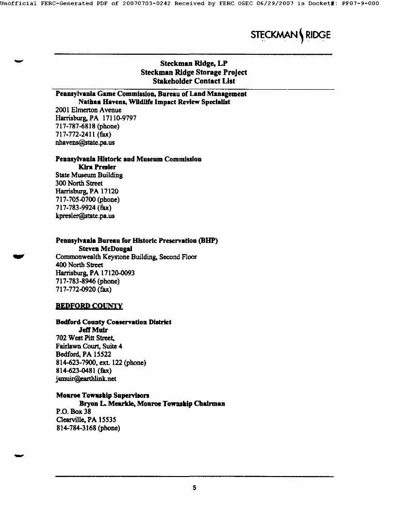
Jnofflclal FERC-Generated PDF of 20070703-0242 Received by FERC OSEC 06/29/2007 in Docket#: PF07-9-000
S CKJV N R,DOE
Steckman Ridge, LP Steckman Ridge Storage Project
Stakeholder Contact List
Pennsylvanla Game CommJs~on, Bureau of Land Management Nathan Havens, WHdllfe Impact Review Specialist
2001 Elmerton Avenue Hat .burg. PA 17110-9797 717-787-6818 (phone) 717-772-2411 (fax) n h a v ~ . p ~ u s
Pennsylvania Historic and Museum Commission Klra Presler
State Museum Building 300 North Street Hardsburg, PA 17120 717-705-0700 (phone) 717-783-9924 (fax) kprcslcr~stete.pa.ua
Pennsylvania Bureau for Historic Preservation (BHP) Steven McDougal
Commonwealth Keystone Building. Second Floor 400 North Steer Harrisbur~ PA 17120-0093 717-783-8946 (phone) 717-772-0920 (fax)
BEDFORD COUNT~
Bedford County Colservatlon DJstrlct Jeff Muir
702 West Pitt Street, Fairlawn Court, Suite 4 Bedford, PA 15522 814-623-7900, ext. 122 (phone) 814-623-o481 (fax)
Monroe Towwklp Supervisors Bryon L. Mearkle, Monroe Towmldp Chairman
P.O. Box 38 ~carville, PA 15535 814-784-3168 (phone)
V
5
Jnofficial FERC-Generated PDF of 20070703-0242 Received by FERC OSEC 06/29/2007 in Docket#: PF07-9-000
sTEC... R,DGE
Steckman Ridge, LP Stockman Ridge Storage Project
Stakeholder Contact List
Bedford County Planning Commle~on Jeffrey W. Klou
P.O. Box 166 Bedford, PA] 5522
Bedford County Development Assodat/on Betto Slayton, President
One Corporate Drive, Suite 10l Bedford, PA 15522 814-623-4816 (phone)
ELECTED OIFI~CIAL~
V
US. House of Representatives The Honorable Bm Shunter
United States House of Representatives 204 Cannon House Office Building Washington, D.C. 20515-3809 202-225-2431 (phone) 202-225-2486 (fax) http://www.house.gov/shuster/zipamh.htm (email)
Peansylvanla State Senate Senator John EL Elehelberger, Jr.
District Address 309 Allegheny St Hollidaysburg, PA 16648 814-695-8386 (phone) 814-695-8398 (fax)
Pennsylvania House of Representatives Hoa- Dick L. Hess
213 Ryan Office Building PO Box 202078 Harrisburg, PA 17120-2078 717-787-7076 (phone) 717-705-1855 (fax)
v

]nofflclal FERC-Generated PDF of 20070703-0242 Received by FERC OSEC 06/29/2007 in Docket#: PF07-9-000
V Steckman Ridge, LP
Steckman Ridge Storage Project Stakeholder Contact List
STECKMAN RIDGE
V
NATIVE AMERICAN TRIBES
Absentee-Shawnee Tribe of Oklahoma Karen Kanlateb~ THPO
2025 S. Gordon Cooper Drive Shawnee, OK 74801 405-275-4030 (phone) 405-878-4533 (fax) kkaniatol~asm~.com
Cayuga Nation Timothy Two GeM
P.O Box 11 Versailles, New York 14168 716-337-4270 (phone) 716-337-0268 (fax)
Delaware Nation of Oklahoma Tamara Francis, NAGPRA Director
Delaware Nation NAGPRA/Cultural Preservation P.O. Box 825 Anadarko, OK 73005 405-247-2448 (phone) 405-247-9393 (fax) t francis~delawarena~on~ corn
Eastora Shawnee Tribe of Oklahoma Roxsne Weldon, EPA Director
P.O Box 350 Seneca, Montana, 64865 918-666-2435 (phone) 918-666-2186 (fax)
Oneida lmdtu Nat:los Authomy Wou~q'ley, Oneida Nation Hlmtoriu
221 Union Street P.O Box 662 Oneida, New York 13421 315-829-8455 (phone) 315-829-8473 (fax) [email protected]

Jnofflclal FERC-Generated PDF of 20070703-0242 Received by FERC OSEC 06/29/2007 in Docket#: PF07-9-000
ECKJ AN R, GE
V Steckman Ridge, LP Steckman Ridge Storage Project
Stakeholder Contact List
Oneida Nation of Wiscoas/n Corina Williams, THPO
P.O Box 365 Oneida, Wiscons'm 54 ! 55-0365 920-496-5386 (phone) 920-494-4362 (fax) c w i l l ~ n e i d a n a f i o n . o r g
V
Onondaga Nation Tony Gonyea, Falthkeeper
RR #1, Route 11A Box 258C via Nedrow, New York 13120 315-492-4210 (phone) 315-469-1725 (fax) ononcomm~verizon.net
St. Regis Mohawk Tribe Sheree Bonaparte, Historic Preservation Oflker
412 State Route 37 Akwesasne, New York 13655 518-358-2272 (phone) 518-358-4302 (fax) shonaperte@snnt-ns~.gov
Seneca Nation of IncUmB Kathleen Mltcht~ TE[PO
467 Center Street Salamanca, New York 14779 716-945-9427 (phone) 716-945-0351 (fax) mthpo~.ors
Senecm-Cayuga Tribe of Oklahoma Paul Barton, B[/mmrle Preservation Ofllcer
P.O Box 1283 Miami, Oklahoma 74355 918-542-6609 (phone) 918-542-3684 (fax) pl=rton@w~n~e.com
V

Jnofflclal FERC-Generated PDF of 20070703-0242 Received by FERC OSEC 06/29/2007 in Docket#: PF07-9-000
STEC. 1 R!DG- E
V Steckmnn Ridge, LP Steckman Ridge Storage Project
Stakeholder Contact List
Shawnee Tribe Rebecca E[awkim,, THPO
29 South 69a Highway Miami, Oklahoma 74354 918-542-2441 (phone) 918-542-9915 (fax) shawaeetribe~neok.com
Stockbridge-Munsee Band of Mohican Nation, WI Sheri White, Tribal Elhtori¢ Preservation Office
W13447 Camp 14 Road Bowler, WI 54416 715-793-4111 (phone) 715-793-4437 (fax) [email protected]
Tonawanda Seneca Nation Roger Hill, Chief
7027 Meadville Road Basom, New York 14013 716-542-4244 (phone) 716-542-4244 (fax) tons~mec(~ffnet.net
Tuscarora Nntioa Stuart Patterson, Chief
1983 Upper Mountain Road Sanborn, New York 14132 716-298-5114 (phone) 716-297-7355 (fax)
9